EP4434800A1 - Battery assembly for a motor vehicle and motor vehicle comprising the same - Google Patents
Battery assembly for a motor vehicle and motor vehicle comprising the same Download PDFInfo
- Publication number
- EP4434800A1 EP4434800A1 EP24164415.2A EP24164415A EP4434800A1 EP 4434800 A1 EP4434800 A1 EP 4434800A1 EP 24164415 A EP24164415 A EP 24164415A EP 4434800 A1 EP4434800 A1 EP 4434800A1
- Authority
- EP
- European Patent Office
- Prior art keywords
- battery assembly
- volume
- inner volume
- container
- opening
- Prior art date
- Legal status (The legal status is an assumption and is not a legal conclusion. Google has not performed a legal analysis and makes no representation as to the accuracy of the status listed.)
- Granted
Links
Images



Classifications
-
- B—PERFORMING OPERATIONS; TRANSPORTING
- B60—VEHICLES IN GENERAL
- B60L—PROPULSION OF ELECTRICALLY-PROPELLED VEHICLES; SUPPLYING ELECTRIC POWER FOR AUXILIARY EQUIPMENT OF ELECTRICALLY-PROPELLED VEHICLES; ELECTRODYNAMIC BRAKE SYSTEMS FOR VEHICLES IN GENERAL; MAGNETIC SUSPENSION OR LEVITATION FOR VEHICLES; MONITORING OPERATING VARIABLES OF ELECTRICALLY-PROPELLED VEHICLES; ELECTRIC SAFETY DEVICES FOR ELECTRICALLY-PROPELLED VEHICLES
- B60L50/00—Electric propulsion with power supplied within the vehicle
- B60L50/50—Electric propulsion with power supplied within the vehicle using propulsion power supplied by batteries or fuel cells
- B60L50/60—Electric propulsion with power supplied within the vehicle using propulsion power supplied by batteries or fuel cells using power supplied by batteries
- B60L50/64—Constructional details of batteries specially adapted for electric vehicles
-
- B—PERFORMING OPERATIONS; TRANSPORTING
- B60—VEHICLES IN GENERAL
- B60L—PROPULSION OF ELECTRICALLY-PROPELLED VEHICLES; SUPPLYING ELECTRIC POWER FOR AUXILIARY EQUIPMENT OF ELECTRICALLY-PROPELLED VEHICLES; ELECTRODYNAMIC BRAKE SYSTEMS FOR VEHICLES IN GENERAL; MAGNETIC SUSPENSION OR LEVITATION FOR VEHICLES; MONITORING OPERATING VARIABLES OF ELECTRICALLY-PROPELLED VEHICLES; ELECTRIC SAFETY DEVICES FOR ELECTRICALLY-PROPELLED VEHICLES
- B60L58/00—Methods or circuit arrangements for monitoring or controlling batteries or fuel cells, specially adapted for electric vehicles
- B60L58/10—Methods or circuit arrangements for monitoring or controlling batteries or fuel cells, specially adapted for electric vehicles for monitoring or controlling batteries
- B60L58/24—Methods or circuit arrangements for monitoring or controlling batteries or fuel cells, specially adapted for electric vehicles for monitoring or controlling batteries for controlling the temperature of batteries
- B60L58/26—Methods or circuit arrangements for monitoring or controlling batteries or fuel cells, specially adapted for electric vehicles for monitoring or controlling batteries for controlling the temperature of batteries by cooling
-
- H—ELECTRICITY
- H01—ELECTRIC ELEMENTS
- H01M—PROCESSES OR MEANS, e.g. BATTERIES, FOR THE DIRECT CONVERSION OF CHEMICAL ENERGY INTO ELECTRICAL ENERGY
- H01M10/00—Secondary cells; Manufacture thereof
- H01M10/42—Methods or arrangements for servicing or maintenance of secondary cells or secondary half-cells
- H01M10/52—Removing gases inside the secondary cell, e.g. by absorption
-
- H—ELECTRICITY
- H01—ELECTRIC ELEMENTS
- H01M—PROCESSES OR MEANS, e.g. BATTERIES, FOR THE DIRECT CONVERSION OF CHEMICAL ENERGY INTO ELECTRICAL ENERGY
- H01M10/00—Secondary cells; Manufacture thereof
- H01M10/60—Heating or cooling; Temperature control
- H01M10/61—Types of temperature control
- H01M10/613—Cooling or keeping cold
-
- H—ELECTRICITY
- H01—ELECTRIC ELEMENTS
- H01M—PROCESSES OR MEANS, e.g. BATTERIES, FOR THE DIRECT CONVERSION OF CHEMICAL ENERGY INTO ELECTRICAL ENERGY
- H01M10/00—Secondary cells; Manufacture thereof
- H01M10/60—Heating or cooling; Temperature control
- H01M10/62—Heating or cooling; Temperature control specially adapted for specific applications
- H01M10/625—Vehicles
-
- H—ELECTRICITY
- H01—ELECTRIC ELEMENTS
- H01M—PROCESSES OR MEANS, e.g. BATTERIES, FOR THE DIRECT CONVERSION OF CHEMICAL ENERGY INTO ELECTRICAL ENERGY
- H01M50/00—Constructional details or processes of manufacture of the non-active parts of electrochemical cells other than fuel cells, e.g. hybrid cells
- H01M50/20—Mountings; Secondary casings or frames; Racks, modules or packs; Suspension devices; Shock absorbers; Transport or carrying devices; Holders
- H01M50/204—Racks, modules or packs for multiple batteries or multiple cells
-
- H—ELECTRICITY
- H01—ELECTRIC ELEMENTS
- H01M—PROCESSES OR MEANS, e.g. BATTERIES, FOR THE DIRECT CONVERSION OF CHEMICAL ENERGY INTO ELECTRICAL ENERGY
- H01M50/00—Constructional details or processes of manufacture of the non-active parts of electrochemical cells other than fuel cells, e.g. hybrid cells
- H01M50/20—Mountings; Secondary casings or frames; Racks, modules or packs; Suspension devices; Shock absorbers; Transport or carrying devices; Holders
- H01M50/204—Racks, modules or packs for multiple batteries or multiple cells
- H01M50/207—Racks, modules or packs for multiple batteries or multiple cells characterised by their shape
- H01M50/209—Racks, modules or packs for multiple batteries or multiple cells characterised by their shape adapted for prismatic or rectangular cells
-
- H—ELECTRICITY
- H01—ELECTRIC ELEMENTS
- H01M—PROCESSES OR MEANS, e.g. BATTERIES, FOR THE DIRECT CONVERSION OF CHEMICAL ENERGY INTO ELECTRICAL ENERGY
- H01M50/00—Constructional details or processes of manufacture of the non-active parts of electrochemical cells other than fuel cells, e.g. hybrid cells
- H01M50/20—Mountings; Secondary casings or frames; Racks, modules or packs; Suspension devices; Shock absorbers; Transport or carrying devices; Holders
- H01M50/233—Mountings; Secondary casings or frames; Racks, modules or packs; Suspension devices; Shock absorbers; Transport or carrying devices; Holders characterised by physical properties of casings or racks, e.g. dimensions
- H01M50/24—Mountings; Secondary casings or frames; Racks, modules or packs; Suspension devices; Shock absorbers; Transport or carrying devices; Holders characterised by physical properties of casings or racks, e.g. dimensions adapted for protecting batteries from their environment, e.g. from corrosion
-
- H—ELECTRICITY
- H01—ELECTRIC ELEMENTS
- H01M—PROCESSES OR MEANS, e.g. BATTERIES, FOR THE DIRECT CONVERSION OF CHEMICAL ENERGY INTO ELECTRICAL ENERGY
- H01M50/00—Constructional details or processes of manufacture of the non-active parts of electrochemical cells other than fuel cells, e.g. hybrid cells
- H01M50/20—Mountings; Secondary casings or frames; Racks, modules or packs; Suspension devices; Shock absorbers; Transport or carrying devices; Holders
- H01M50/244—Secondary casings; Racks; Suspension devices; Carrying devices; Holders characterised by their mounting method
-
- H—ELECTRICITY
- H01—ELECTRIC ELEMENTS
- H01M—PROCESSES OR MEANS, e.g. BATTERIES, FOR THE DIRECT CONVERSION OF CHEMICAL ENERGY INTO ELECTRICAL ENERGY
- H01M50/00—Constructional details or processes of manufacture of the non-active parts of electrochemical cells other than fuel cells, e.g. hybrid cells
- H01M50/20—Mountings; Secondary casings or frames; Racks, modules or packs; Suspension devices; Shock absorbers; Transport or carrying devices; Holders
- H01M50/249—Mountings; Secondary casings or frames; Racks, modules or packs; Suspension devices; Shock absorbers; Transport or carrying devices; Holders specially adapted for aircraft or vehicles, e.g. cars or trains
-
- H—ELECTRICITY
- H01—ELECTRIC ELEMENTS
- H01M—PROCESSES OR MEANS, e.g. BATTERIES, FOR THE DIRECT CONVERSION OF CHEMICAL ENERGY INTO ELECTRICAL ENERGY
- H01M50/00—Constructional details or processes of manufacture of the non-active parts of electrochemical cells other than fuel cells, e.g. hybrid cells
- H01M50/20—Mountings; Secondary casings or frames; Racks, modules or packs; Suspension devices; Shock absorbers; Transport or carrying devices; Holders
- H01M50/271—Lids or covers for the racks or secondary casings
-
- H—ELECTRICITY
- H01—ELECTRIC ELEMENTS
- H01M—PROCESSES OR MEANS, e.g. BATTERIES, FOR THE DIRECT CONVERSION OF CHEMICAL ENERGY INTO ELECTRICAL ENERGY
- H01M2220/00—Batteries for particular applications
- H01M2220/20—Batteries in motive systems, e.g. vehicle, ship, plane
-
- Y—GENERAL TAGGING OF NEW TECHNOLOGICAL DEVELOPMENTS; GENERAL TAGGING OF CROSS-SECTIONAL TECHNOLOGIES SPANNING OVER SEVERAL SECTIONS OF THE IPC; TECHNICAL SUBJECTS COVERED BY FORMER USPC CROSS-REFERENCE ART COLLECTIONS [XRACs] AND DIGESTS
- Y02—TECHNOLOGIES OR APPLICATIONS FOR MITIGATION OR ADAPTATION AGAINST CLIMATE CHANGE
- Y02E—REDUCTION OF GREENHOUSE GAS [GHG] EMISSIONS, RELATED TO ENERGY GENERATION, TRANSMISSION OR DISTRIBUTION
- Y02E60/00—Enabling technologies; Technologies with a potential or indirect contribution to GHG emissions mitigation
- Y02E60/10—Energy storage using batteries
Definitions
- the invention relates to a battery assembly for a motor vehicle and to a motor vehicle comprising a battery assembly.
- electric or hybrid motor vehicles basically comprise:
- motor vehicles which comprise systems for the adjustment of the temperature of the batteries.
- batteries operating at temperatures close to or below ambient temperature are characterised by a greater efficiency compared to batteries operating at higher temperatures. This allows manufacturers to reduce the portion of vehicle weight used to store power.
- the humidity of the air naturally present in the container of the batteries tends to condense as the temperature of the batteries decreases.
- the inner walls of the container act as condensing plates for said humidity, which, once liquefied, tends to gather at the bottom of the container.
- the object of the invention is to fulfil the need discussed above, preferably in a simple and reliable fashion.
- reference number 1 is used to indicate, as a whole, an electric or hybrid motor vehicle comprising:
- the vehicle 1 defines a front portion 1a and a rear portion 1b opposite one another along a longitudinal direction X of the vehicle. Therefore, there are a pair of front wheels 3 arranged at front portion 1a and a pair of rear wheels 4 arranged at rear portion 1b.
- the vehicle 1 could comprise an internal combustion engine and/or fuel cells.
- the vehicle 1 preferably is a sports car.
- the frame 2 defines, in turn, a passenger compartment 20 adapted to accommodate the driver and possible passengers and comprising one or more seats 21.
- the vehicle 1 comprises one single pair of seats 21 ( Figure 1 ).
- the frame 2 also comprises a floorboard 22, which constitutes the portion of the frame 2 closest to the ground along a direction Z, which is orthogonal to the longitudinal direction X and to the ground on which the wheels 3, 4 rest ( Figure 1 ).
- the battery assembly 10 comprises, in turn, a case 11 defining an inner volume 12a, 12b, which is fluidly isolated from outside atmospheric air, and a plurality of batteries 13 accommodated in the inner volume 12a, 12b.
- Outside atmospheric air means air present on the outside of the inner volume 12a, 12b. In particular, said outside atmospheric air could be inside the motor vehicle 1 or it could directly come from the outside of the motor vehicle 1.
- the battery assembly 10 comprises a front group 10a and a rear group 10b opposite one another along the longitudinal direction X.
- the extension of the front group 10a along the direction Z is smaller than the extension of the rear group 10b along the direction Z ( Figure 2 ).
- the battery assembly 10 is interposed between the front wheels 3 and the rear wheels 4 along the longitudinal direction X. More in detail, the front group 10a is located immediately under the seats 21 along the direction Z and the rear group 10b is located behind the seats 21 along the longitudinal direction X ( Figure 1 ).
- the front and rear groups 10a, 10b are mechanically connected to one another.
- the case 11 comprises:
- the inner volume 12a is the volume enclosed by the base body 30 and by the lid 35 and the inner volume 12b is the volume enclosed by the base body 30 and by the lid 36.
- the inner volumes 12a and 12b are fluidly isolated from one another.
- the base body 30 comprises, in turn:
- the front and rear groups 10a, 10b are arranged at an angle relative to one another ( Figure 1 ).
- the plate 31 is parallel or substantially parallel to the ground and the plate 32 is inclined relative to the plate 31. More in detail, moving along the longitudinal direction X from the front portion 1a to the rear portion 1b, the distance between the rear group 10b and the ground along the direction Z increases in a progressive manner.
- the rear group 10b is inclined at an angle smaller than 10° - preferably ranging from 3° to 5° - relative to the front group 10a.
- the front group 10a and the rear group 10b each comprise a plurality of batteries 13 next to one another and grouped in modules 40.
- the batteries 13 preferably are alike and have a cylindrical shape.
- Each module 40 comprises a base plate 41 and a plate 42 opposite the plate 41 along the direction Z, the batteries 13 belonging to the module being interposed between them. Furthermore, the batteries 13 of each module 40 are parallel to or substantially parallel to the direction Z.
- Each module 40 can further comprise a plurality of columns 43, which are also interposed between the plate 41 and the relative plate 42. The assembly formed by the plates 41, 42 and by the columns 43 - if present - is adapted to support the batteries 13 and hold them firmly relative to one another.
- the plates 41, 42 of the modules 40 of the front group 10a have trapezoid-like or substantially trapezoid-like shapes; the plates 41, 42 of the modules 40 of the rear group 10b are rectangular and are equal to one another.
- the front group 10a comprises one single layer of modules 40 coplanar to one another and fixed to the plate 31.
- the rear group 10b comprises a plurality of layers of modules 40 stacked on top of one another parallel to the direction Z.
- the plate 42 of each module 40 serves as base plate 41 of the respective module 40 arranged immediately on top of it along the direction Z.
- the arrangement of the batteries 13 in the battery assembly 10 preferably is symmetrical relative to a middle plane parallel to the directions X and Z.
- the battery assembly 10 can further comprise one or more power electronics devices (for example, inverters, choppers, switching devices) accommodated at the inner volume 12a, 12b.
- power electronics devices for example, inverters, choppers, switching devices
- the vehicle 1 also comprises a cooling system 50 (only partly shown in Figure 2 ) adapted to limit the temperature of the batteries 13.
- the temperature of the batteries 13 is the temperature measured at the outer surface of the batteries, close to it, or at the inner volume 12a, 12b in general.
- the cooling system 50 comprises a circuit, where a cooling fluid flows, and a cooling fluid circulating pump, which is known per se and not shown herein.
- the circuit comprises, in turn:
- the fluid path 53 comprises at least some of the plates 41 and 42, which are hollow and are adapted to be flown through by the cooling fluid, and a plurality of ducts, which establish a fluid communication between the openings 51, 52 and the plates 41, 42 and between the plates 41, 42.
- the battery assembly 10 advantageously comprises a passive dehydrating device 14 and an exchange volume 15, which accommodates the dehydrating device 14 and is selectively positionable in:
- the battery assembly 10 comprises one single dehydrating device 14 adapted to dehumidify the inner volume 12b
- the battery assembly 10 could comprise - alternatively or in addition - a dehydrating device 14 adapted to dehumidify the inner volume 12a.
- a dehydrating device 14 adapted to dehumidify the inner volume 12a.
- a passive dehydrating device is a device capable of absorbing humidity from the air contained in the inner volume 12a, 12b due to the difference in concentration of humidity between the respective inner volume 12a, 12b and the dehydrating device 14.
- the operation of the dehydrating device 14 is based on the law of diffusion of humidity from the inner volume 12a, 12b to the dehydrating device 14. Therefore, the dehydrating device 14 is adapted to reduce the concentration of humidity in the relative inner volume 12a, 12b without requiring the supply of further energy.
- the dehydrating device 14 comprises a hygroscopic salt cartridge.
- the battery assembly 10 comprises a container 16, which defines the exchange volume 15 and comprises an opening 17.
- the opening 17 faces the inner volume 12b and establishes a fluid communication between the exchange volume 15 and the inner volume 12b ( Figure 5 ).
- the dehydrating device 14 is adapted to absorb humidity from the air contained in the inner volume 12b.
- the container 16 can rotate relative to the case 11 between the first and the second position around a rotational axis C, which is parallel or substantially parallel to the direction Z ( Figures 6, 7 and 8 ).
- the rotation of the container 16 corresponds to a variation in the position of the opening 17 relative to the inner volume 12b.
- the case 11 comprises an opening 18, at which it is operatively coupled to the container 16. In the absence of the container 16, the opening 18 would establish a direct fluid communication between the inner volume 12b and outside atmospheric air.
- the battery assembly 10 further comprises seals 19a, 19b, 19c, 19d interposed between the opening 18 and the container 16 ( Figure 8 ).
- the seals 19a, 19b, 19c, 19d are adapted to prevent outside air from flowing into the inner volume 12b in an undesired manner.
- the seals 19a, 19b, 19c, 19d are adapted to avoid the undesired inflow of outside air both when the exchange volume 15 is in the first or in the second position and during the movement of the exchange volume 15 between the first and the second position.
- the container 16 has a prismatic shape and comprises:
- the side walls 16c and 16e are curved; the walls 16d and 16f are flat and perpendicular to the walls 16a and 16b. More in detail, moving around the axis C in a clockwise direction, the walls 16c, 16d, 16e and 16f are arranged in succession ( Figures 6 and 7 ).
- the container 16 comprises the opening 17 at the wall 16f.
- the opening 17 preferably has a rectangular shape and has dimensions that are larger than or equal to the dimensions of the dehydrating device 14 ( Figure 6 ).
- the opening 18 has a shape corresponding to the outer shape of the container 16 ( Figure 8 ).
- the case 11 comprises a wall 18a and a wall 18b, both extending starting from the lid 36 towards the inner volume 12b and defining the opening 18.
- the walls 18a and 18b face the walls 16a and 16e of the container 16, respectively, and are shaped so as to allow the container 16 to rotate relative to the case 11 around the axis C (the shape of the walls 18a and 18b in Figure 8 is a mere example).
- the seals 19a, 19b, 19c, 19d are threadlike and are fixed to the outer surface of the container 16.
- the seal 19a is arranged at the wall 16f;
- the seal 19b is arranged at the wall 16d and the seals 19c and 19d are arranged in an intermediate position between the wall 16d and the wall 16f.
- the seal 19a extends at the edge between the wall 16f and the walls 16a, 16c, 16e adjacent thereto; the seal 19b extends at the edge between the wall 16d and the walls 16a, 16c, 16e adjacent thereto; the seal 19c extends along the walls 16c and 16e parallel to the axis C and along the wall 16b perpendicularly to the axis C; the seal 19d extends along the wall 16b and joins the seal 19a to the seal 19c.
- the seals 19a, 19c and 19d preferably form one single body.
- the battery assembly 10 stores electrical energy and powers the electric motors 5. During its operation, the temperature of the batteries is limited by the cooling system 50.
- the exchange volume 15 Since the exchange volume 15 is in the first position, the exchange volume 15 is fluidly connected to the inner volume 12b and fluidly isolated from outside atmospheric air. As a consequence, the dehydrating device 14 absorbs the humidity of the air contained in the inner volume 12b due to the difference in concentration of humidity between the inner volume 12b and the dehydrating device 14. In this condition, the wall 16d faces the opening 18 ( Figure 5 ).
- the container 16 is rotated about the axis C, until the exchange volume 15 reaches the second position ( Figures 4 and 8 ). In this position, the exchange volume 15 is fluidly isolated from the inner volume 12b and the dehydrating device 14 is accessible through the opening 18.
- the seals 19a, 19b, 19c, 19d prevent outside atmospheric air from flowing into the inner volume 12b in an undesired manner.
- the battery assembly 10 comprises the dehydrating device 14, which is selectively fluidly connected to the inner volume 12b, the level of humidity in the inner volume 12b can be limited in a simple and economic fashion. As a consequence, the risk of short circuits due to the formation of condensate in the inner volume 12b can be reduced.
- the exchange volume 15 can selectively be shifted to the first or to the second position, the dehydrating device 14 can be replaced during maintenance operations without allowing outside air to flow into the inner volume 12b.
- the exchange volume 15 can be fluidly connected to the sole outside air or to the sole inner volume 12b and cannot be fluidly connected to the outside air and to the inner volume 12b at the same time. As a consequence, the exchange volume 15 acts as compensation chamber.
- the level of humidity in the inner volume 12a, 12b can be limited without having to use external energy.
- the exchange volume 15 is movable relative to the case 11 with a rotation movement about the axis C, the shift between the first and the second position can be carried out by hand in a user-friendly and efficient manner.
- the battery assembly 10 comprises the seals 19a, 19b, 19c, 19d, it is possible to ensure that outside air does not reach, in an undesired manner, the inner volume 12a, 12b, for example during the rotation of the exchange volume 15. The inflow of outside air, indeed, would make the dehydrating device 14 ineffective.
- the battery assembly 10 could comprise more than one dehydrating device 14.
- the battery assembly 10 could comprise more than one dehydrating device 14 at the front group 10a and/or more than one dehydrating device 14 at the rear group 10b.
Landscapes
- Engineering & Computer Science (AREA)
- General Chemical & Material Sciences (AREA)
- Electrochemistry (AREA)
- Chemical Kinetics & Catalysis (AREA)
- Chemical & Material Sciences (AREA)
- Manufacturing & Machinery (AREA)
- Sustainable Energy (AREA)
- Mechanical Engineering (AREA)
- Transportation (AREA)
- Power Engineering (AREA)
- Life Sciences & Earth Sciences (AREA)
- Sustainable Development (AREA)
- Aviation & Aerospace Engineering (AREA)
- Arrangement Or Mounting Of Propulsion Units For Vehicles (AREA)
Abstract
Description
- This patent application claims priority from
Italian patent application no. 102023000005277 filed on March 21, 2023 - The invention relates to a battery assembly for a motor vehicle and to a motor vehicle comprising a battery assembly.
- As it is known electric or hybrid motor vehicles basically comprise:
- a frame;
- a plurality of wheels, which can rotate relative to the frame around respective rotational axes and are adapted to move the frame relative to the ground on which they rest;
- one or more electric motor means adapted to cause the wheels to rotate around the respective axes;
- one or more batteries electrically connected to the electric motors and accommodated inside a suitable container.
- Furthermore, motor vehicles are known, which comprise systems for the adjustment of the temperature of the batteries. As a matter of fact, batteries operating at temperatures close to or below ambient temperature are characterised by a greater efficiency compared to batteries operating at higher temperatures. This allows manufacturers to reduce the portion of vehicle weight used to store power.
- However, the humidity of the air naturally present in the container of the batteries tends to condense as the temperature of the batteries decreases. In particular, the inner walls of the container act as condensing plates for said humidity, which, once liquefied, tends to gather at the bottom of the container.
- Since the overall dimensions of the container of the batteries in electric or hybrid vehicles can be very large, the quantity of condensate forming in the container risks determining short circuits.
- Owing to the above, known motor vehicles need to be improved in order to limit the risk of short circuits due to the condensate forming in the containers of the batteries.
- The object of the invention is to fulfil the need discussed above, preferably in a simple and reliable fashion.
- Said object is reached by a battery assembly for a motor vehicle as defined in claim 1.
- The dependent claims define special embodiments of the invention.
- Hereinafter, an embodiment of the invention will be described, in order to allow the latter to be better understood, by way of non-limiting example and with reference to the accompanying drawings, wherein:
-
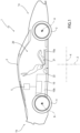
Figure 1 is a schematic side view of a motor vehicle comprising a battery assembly according to the invention and with parts removed for greater clarity; -
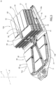
Figure 2 is a perspective view of the battery assembly ofFigure 1 ; -
Figure 3 is a perspective view of the battery assembly ofFigure 1 or2 with parts removed for greater clarity; -
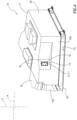
Figures 4 and5 show the battery assembly in respective operating positions; -
Figures 6 and 7 are perspective views of a component of the battery assembly ofFigures 1 to 5 ; and -
Figure 8 is a perspective sectional view of the battery assembly ofFigure 4 with parts removed for greater clarity and on a much larger scale. - In
figure 1 , reference number 1 is used to indicate, as a whole, an electric or hybrid motor vehicle comprising: - a
frame 2; - a plurality of wheels 3, 4, which can rotate around respective rotational axes A, B relative to
frame 2; - one or more electric motors 5 - only schematically shown - adapted to cause the wheels 3, 4 to rotate about the respective axes A, B; and
- a
battery assembly 10. - The vehicle 1 defines a
front portion 1a and arear portion 1b opposite one another along a longitudinal direction X of the vehicle. Therefore, there are a pair of front wheels 3 arranged atfront portion 1a and a pair of rear wheels 4 arranged atrear portion 1b. - The vehicle 1 could comprise an internal combustion engine and/or fuel cells. In addition, the vehicle 1 preferably is a sports car.
- The
frame 2 defines, in turn, apassenger compartment 20 adapted to accommodate the driver and possible passengers and comprising one ormore seats 21. In the specific case shown herein, the vehicle 1 comprises one single pair of seats 21 (Figure 1 ). - The
frame 2 also comprises afloorboard 22, which constitutes the portion of theframe 2 closest to the ground along a direction Z, which is orthogonal to the longitudinal direction X and to the ground on which the wheels 3, 4 rest (Figure 1 ). - The
battery assembly 10 comprises, in turn, acase 11 defining aninner volume batteries 13 accommodated in theinner volume - "Outside atmospheric air" means air present on the outside of the
inner volume - In the specific case shown herein, the
battery assembly 10 comprises afront group 10a and arear group 10b opposite one another along the longitudinal direction X. In detail, the extension of thefront group 10a along the direction Z is smaller than the extension of therear group 10b along the direction Z (Figure 2 ). - The
battery assembly 10 is interposed between the front wheels 3 and the rear wheels 4 along the longitudinal direction X. More in detail, thefront group 10a is located immediately under theseats 21 along the direction Z and therear group 10b is located behind theseats 21 along the longitudinal direction X (Figure 1 ). - As shown in
Figures 2 and3 , the front andrear groups case 11 comprises: - a
base body 30, to which the front andrear groups floorboard 22; - a
lid 35, which is coupled to thebase body 30 and covers thebatteries 13 of thefront group 10a; and - a
lid 36, which is coupled to thebase body 30 and covers thebatteries 13 of therear group 10b. - The
inner volume 12a is the volume enclosed by thebase body 30 and by thelid 35 and theinner volume 12b is the volume enclosed by thebase body 30 and by thelid 36. In the specific case shown herein, theinner volumes - The
base body 30 comprises, in turn: - a
plate 31 at thefront group 10a; and - a
plate 32 at therear group 10b, which is joined to or integrated in the plate 31 (Figure 2 ). - The front and
rear groups Figure 1 ). In detail, theplate 31 is parallel or substantially parallel to the ground and theplate 32 is inclined relative to theplate 31. More in detail, moving along the longitudinal direction X from thefront portion 1a to therear portion 1b, the distance between therear group 10b and the ground along the direction Z increases in a progressive manner. Therear group 10b is inclined at an angle smaller than 10° - preferably ranging from 3° to 5° - relative to thefront group 10a. - As shown in
Figure 3 , thefront group 10a and therear group 10b each comprise a plurality ofbatteries 13 next to one another and grouped inmodules 40. Thebatteries 13 preferably are alike and have a cylindrical shape. - Each
module 40 comprises abase plate 41 and aplate 42 opposite theplate 41 along the direction Z, thebatteries 13 belonging to the module being interposed between them. Furthermore, thebatteries 13 of eachmodule 40 are parallel to or substantially parallel to the direction Z. Eachmodule 40 can further comprise a plurality ofcolumns 43, which are also interposed between theplate 41 and therelative plate 42. The assembly formed by theplates batteries 13 and hold them firmly relative to one another. - In the specific case shown herein, the
plates modules 40 of thefront group 10a have trapezoid-like or substantially trapezoid-like shapes; theplates modules 40 of therear group 10b are rectangular and are equal to one another. - The
front group 10a comprises one single layer ofmodules 40 coplanar to one another and fixed to theplate 31. Therear group 10b comprises a plurality of layers ofmodules 40 stacked on top of one another parallel to the direction Z. In particular, in therear group 10b, theplate 42 of eachmodule 40 serves asbase plate 41 of therespective module 40 arranged immediately on top of it along the direction Z. - The arrangement of the
batteries 13 in thebattery assembly 10 preferably is symmetrical relative to a middle plane parallel to the directions X and Z. - The
battery assembly 10 can further comprise one or more power electronics devices (for example, inverters, choppers, switching devices) accommodated at theinner volume - The vehicle 1 also comprises a cooling system 50 (only partly shown in
Figure 2 ) adapted to limit the temperature of thebatteries 13. The temperature of thebatteries 13 is the temperature measured at the outer surface of the batteries, close to it, or at theinner volume - The
cooling system 50 comprises a circuit, where a cooling fluid flows, and a cooling fluid circulating pump, which is known per se and not shown herein. - The circuit comprises, in turn:
- an
inlet opening 51 adapted to allow the cooling fluid to flow into theinner volume - an
outlet opening 52 adapted to allow the cooling fluid to flow out of theinner volume - a
fluid path 53, which is fluidly interposed between theinlet opening 51 and theoutlet opening 52 and extends inside thebattery assembly 10. - The
fluid path 53 comprises at least some of theplates openings plates plates - The
battery assembly 10 advantageously comprises apassive dehydrating device 14 and anexchange volume 15, which accommodates the dehydratingdevice 14 and is selectively positionable in: - a first position, in which the
exchange volume 15 is fluidly connected to theinner volume 12b and fluidly isolated from outside atmospheric air (Figure 5 ); or - a second position, in which the
exchange volume 15 is fluidly isolated from theinner volume 12b and fluidly connected to outside atmospheric air (Figures 4 and8 ). - Even though, in the embodiment shown herein, the
battery assembly 10 comprises onesingle dehydrating device 14 adapted to dehumidify theinner volume 12b, thebattery assembly 10 could comprise - alternatively or in addition - adehydrating device 14 adapted to dehumidify theinner volume 12a. For the sake of brevity, hereinafter reference will be made to onesingle dehydrating device 14, since all considerations made for one of them also apply to the other ones. - A passive dehydrating device is a device capable of absorbing humidity from the air contained in the
inner volume inner volume device 14. The operation of the dehydratingdevice 14 is based on the law of diffusion of humidity from theinner volume device 14. Therefore, the dehydratingdevice 14 is adapted to reduce the concentration of humidity in the relativeinner volume - Specifically, the dehydrating
device 14 comprises a hygroscopic salt cartridge. - As shown in
Figures 4 to 8 , thebattery assembly 10 comprises acontainer 16, which defines theexchange volume 15 and comprises anopening 17. - In detail, when the
exchange volume 15 is in the first position, theopening 17 faces theinner volume 12b and establishes a fluid communication between theexchange volume 15 and theinner volume 12b (Figure 5 ). In this condition, the dehydratingdevice 14 is adapted to absorb humidity from the air contained in theinner volume 12b. - When the
exchange volume 15 is in the second position, theopening 17 is fluidly isolated from theinner volume 12b and is accessible from the outside of the battery assembly 10 (Figures 4 and8 ). In this condition, the dehydratingdevice 14 is accessible from the outside of thebattery assembly 10 and can be replaced during maintenance operations. - In the embodiment shown herein, the
container 16 can rotate relative to thecase 11 between the first and the second position around a rotational axis C, which is parallel or substantially parallel to the direction Z (Figures 6, 7 and8 ). In detail, the rotation of thecontainer 16 corresponds to a variation in the position of theopening 17 relative to theinner volume 12b. - More in detail, the
case 11 comprises anopening 18, at which it is operatively coupled to thecontainer 16. In the absence of thecontainer 16, theopening 18 would establish a direct fluid communication between theinner volume 12b and outside atmospheric air. - The
battery assembly 10 further comprisesseals opening 18 and the container 16 (Figure 8 ). Theseals inner volume 12b in an undesired manner. In particular, theseals exchange volume 15 is in the first or in the second position and during the movement of theexchange volume 15 between the first and the second position. - As shown in
Figures 6 and 7 , thecontainer 16 has a prismatic shape and comprises: - a
base wall 16a, which is flat and orthogonal to the axis C; - a
flat wall 16b, which is parallel to thewall 16a and opposite the latter along the axis C; and - a plurality of
side walls wall 16a and thewall 16b along the axis C. - In detail, the
side walls walls walls walls Figures 6 and 7 ). - The
container 16 comprises theopening 17 at thewall 16f. Theopening 17 preferably has a rectangular shape and has dimensions that are larger than or equal to the dimensions of the dehydrating device 14 (Figure 6 ). - The
opening 18 has a shape corresponding to the outer shape of the container 16 (Figure 8 ). In detail, thecase 11 comprises awall 18a and awall 18b, both extending starting from thelid 36 towards theinner volume 12b and defining theopening 18. More in detail, thewalls walls container 16, respectively, and are shaped so as to allow thecontainer 16 to rotate relative to thecase 11 around the axis C (the shape of thewalls Figure 8 is a mere example). - In the embodiment shown herein, the
seals container 16. In detail, theseal 19a is arranged at thewall 16f; theseal 19b is arranged at thewall 16d and theseals wall 16d and thewall 16f. - More in detail, the
seal 19a extends at the edge between thewall 16f and thewalls seal 19b extends at the edge between thewall 16d and thewalls seal 19c extends along thewalls wall 16b perpendicularly to the axis C; theseal 19d extends along thewall 16b and joins theseal 19a to theseal 19c. Theseals - The operation of the
battery assembly 10 will be described hereinafter starting from a condition in which theexchange volume 15 is in the first position. - In use, the
battery assembly 10 stores electrical energy and powers theelectric motors 5. During its operation, the temperature of the batteries is limited by thecooling system 50. - Since the
exchange volume 15 is in the first position, theexchange volume 15 is fluidly connected to theinner volume 12b and fluidly isolated from outside atmospheric air. As a consequence, the dehydratingdevice 14 absorbs the humidity of the air contained in theinner volume 12b due to the difference in concentration of humidity between theinner volume 12b and the dehydratingdevice 14. In this condition, thewall 16d faces the opening 18 (Figure 5 ). - During the maintenance and replacement operations to which the
dehydrating device 14 is subjected, thecontainer 16 is rotated about the axis C, until theexchange volume 15 reaches the second position (Figures 4 and8 ). In this position, theexchange volume 15 is fluidly isolated from theinner volume 12b and the dehydratingdevice 14 is accessible through theopening 18. - In detail, during the rotation between the first and the second position, the
seals inner volume 12b in an undesired manner. - Owing to the above, the advantages of the
battery assembly 10 and of the motor vehicle 1 according to the invention are evident. - Since the
battery assembly 10 comprises the dehydratingdevice 14, which is selectively fluidly connected to theinner volume 12b, the level of humidity in theinner volume 12b can be limited in a simple and economic fashion. As a consequence, the risk of short circuits due to the formation of condensate in theinner volume 12b can be reduced. - Since the
exchange volume 15 can selectively be shifted to the first or to the second position, the dehydratingdevice 14 can be replaced during maintenance operations without allowing outside air to flow into theinner volume 12b. As a matter of fact, theexchange volume 15 can be fluidly connected to the sole outside air or to the soleinner volume 12b and cannot be fluidly connected to the outside air and to theinner volume 12b at the same time. As a consequence, theexchange volume 15 acts as compensation chamber. - Because of the fact that the dehydrating
device 14 is of the passive kind, the level of humidity in theinner volume - Since the
exchange volume 15 is movable relative to thecase 11 with a rotation movement about the axis C, the shift between the first and the second position can be carried out by hand in a user-friendly and efficient manner. - Since the
battery assembly 10 comprises theseals inner volume exchange volume 15. The inflow of outside air, indeed, would make the dehydratingdevice 14 ineffective. - Finally, the
battery assembly 10 and the motor vehicle 1 according to the invention can be subjected to changes and variants, which, though, do not go beyond the scope of protection set forth in the appended claims. - In particular, the
battery assembly 10 could comprise more than onedehydrating device 14. For instance, thebattery assembly 10 could comprise more than onedehydrating device 14 at thefront group 10a and/or more than onedehydrating device 14 at therear group 10b.
Claims (10)
- Battery assembly (10) for a motor vehicle (1), comprising:- a case (11) defining an inner volume (12a, 12b); said inner volume (12a, 12b) being fluidly isolated from outside atmospheric air;- a plurality of batteries (13) arranged within said inner volume (12a, 12b);- at least one passive dehydrating device (14);- an exchange volume (15) housing said dehydrating device (14);wherein said exchange volume (15) is selectively positionable relative to said case (11) in:- a first position, wherein said exchange volume (15) is fluidly connected to said inner volume (12a, 12b) and fluidly isolated from outside atmospheric air; or- a second position, wherein said exchange volume (15) is fluidly isolated from said inner volume (12a, 12b) and fluidly connected to outside atmospheric air.
- Battery assembly according to claim 1, wherein said dehydrating device (14) comprises a hygroscopic salt cartridge.
- Battery assembly according to claim 1 or 2, further comprising a container (16) defining said exchange volume (15) and comprising at least one opening (17);said opening (17) facing said inner volume (12a, 12b) when said exchange volume (15) is, in use, in said first position;said opening (17) being fluidly isolated from said inner volume (12a, 12b) and accessible from the outside of said battery assembly (10) when said exchange volume (15) is, in use, in said second position.
- Battery assembly according to claim 3, wherein said opening (17) is conformed to allow, in use, said dehydrating device (14) to be inserted and removed from said container (16), when said exchange volume (15) is, in use, in said second position.
- Battery assembly according to claim 3 or 4, wherein said container (16) is rotatable relative to said case (11) about a rotational axis (C).
- Battery assembly according to any one of claims 3 to 5, wherein said case (11) comprises a further opening (18); said container (16) being operatively coupled to said case (11) at said further opening (18);
said battery assembly (10) further comprising sealing means (19a, 19b, 19c) interposed between said further opening (18) and said container (16). - Battery assembly according to claim 6, wherein said container (16) ha a prismatic shape and said further opening (18) has a shape corresponding to said container (16).
- Battery assembly according to any one of the foregoing claims, characterized in that it comprises one or more power electronic devices.
- Motor vehicle(1) comprising:- a frame (2);- a plurality of wheels (3, 4) rotatable about respective rotational axes (A, B) relative to said frame (2) ;- electrical motor means (5) operatively connected to said wheels (3, 4) and adapted to drive said wheels (3, 4) in rotation about said rotational axes (A, B);- a battery assembly (10) according to any one of the foregoing claims; said plurality of batteries (13) of said battery assembly (10) being electrically connected to said electrical motor means (5).
- Motor vehicle according to claim 9, comprising a cooling system (50) adapted to limit the temperature of said batteries (13).
Applications Claiming Priority (1)
| Application Number | Priority Date | Filing Date | Title |
|---|---|---|---|
| IT102023000005277A IT202300005277A1 (en) | 2023-03-21 | 2023-03-21 | BATTERY ASSEMBLY FOR A CAR AND CAR COMPRISING THE SAME |
Publications (2)
| Publication Number | Publication Date |
|---|---|
| EP4434800A1 true EP4434800A1 (en) | 2024-09-25 |
| EP4434800B1 EP4434800B1 (en) | 2026-01-21 |
Family
ID=86657225
Family Applications (1)
| Application Number | Title | Priority Date | Filing Date |
|---|---|---|---|
| EP24164415.2A Active EP4434800B1 (en) | 2023-03-21 | 2024-03-19 | Battery assembly for a motor vehicle and motor vehicle comprising the same |
Country Status (4)
| Country | Link |
|---|---|
| US (1) | US20240317076A1 (en) |
| EP (1) | EP4434800B1 (en) |
| CN (1) | CN118693383A (en) |
| IT (1) | IT202300005277A1 (en) |
Families Citing this family (1)
| Publication number | Priority date | Publication date | Assignee | Title |
|---|---|---|---|---|
| DE102020110744A1 (en) * | 2020-04-21 | 2021-11-18 | Bayerische Motoren Werke Aktiengesellschaft | Method for arranging a high-voltage storage device having a plurality of battery modules on a support structure of a motor vehicle and a high-voltage storage arrangement |
Citations (7)
| Publication number | Priority date | Publication date | Assignee | Title |
|---|---|---|---|---|
| US20150037649A1 (en) * | 2013-07-30 | 2015-02-05 | Johnson Controls Technology Company | Remanufacturing methods for battery module |
| US20150037616A1 (en) * | 2013-07-30 | 2015-02-05 | Johnson Controls Technology Company | Lithium ion battery with lead acid form factor |
| US20150372355A1 (en) * | 2014-06-20 | 2015-12-24 | GM Global Technology Operations LLC | Cell cooling frames with cantilevered side seals |
| US20170225588A1 (en) * | 2016-02-09 | 2017-08-10 | NextEv USA, Inc. | Modular battery assembly |
| US20170279169A1 (en) * | 2014-09-26 | 2017-09-28 | Obrist Technologies Gmbh | Battery system with cooling device |
| US20210178902A1 (en) * | 2019-12-11 | 2021-06-17 | GM Global Technology Operations LLC | Electronic power module assemblies and control logic with direct-cooling heat pipe systems |
| US20210195808A1 (en) * | 2019-12-23 | 2021-06-24 | GM Global Technology Operations LLC | Electronic power module assemblies and control logic with direct-cooling vapor chamber systems |
-
2023
- 2023-03-21 IT IT102023000005277A patent/IT202300005277A1/en unknown
-
2024
- 2024-03-19 EP EP24164415.2A patent/EP4434800B1/en active Active
- 2024-03-20 US US18/610,371 patent/US20240317076A1/en active Pending
- 2024-03-20 CN CN202410321146.XA patent/CN118693383A/en active Pending
Patent Citations (8)
| Publication number | Priority date | Publication date | Assignee | Title |
|---|---|---|---|---|
| US20150037649A1 (en) * | 2013-07-30 | 2015-02-05 | Johnson Controls Technology Company | Remanufacturing methods for battery module |
| US20150037616A1 (en) * | 2013-07-30 | 2015-02-05 | Johnson Controls Technology Company | Lithium ion battery with lead acid form factor |
| EP3961779A1 (en) * | 2013-07-30 | 2022-03-02 | CPS Technology Holdings LLC | Lithium ion battery with lead acid form factor |
| US20150372355A1 (en) * | 2014-06-20 | 2015-12-24 | GM Global Technology Operations LLC | Cell cooling frames with cantilevered side seals |
| US20170279169A1 (en) * | 2014-09-26 | 2017-09-28 | Obrist Technologies Gmbh | Battery system with cooling device |
| US20170225588A1 (en) * | 2016-02-09 | 2017-08-10 | NextEv USA, Inc. | Modular battery assembly |
| US20210178902A1 (en) * | 2019-12-11 | 2021-06-17 | GM Global Technology Operations LLC | Electronic power module assemblies and control logic with direct-cooling heat pipe systems |
| US20210195808A1 (en) * | 2019-12-23 | 2021-06-24 | GM Global Technology Operations LLC | Electronic power module assemblies and control logic with direct-cooling vapor chamber systems |
Also Published As
| Publication number | Publication date |
|---|---|
| US20240317076A1 (en) | 2024-09-26 |
| IT202300005277A1 (en) | 2024-09-21 |
| CN118693383A (en) | 2024-09-24 |
| EP4434800B1 (en) | 2026-01-21 |
Similar Documents
| Publication | Publication Date | Title |
|---|---|---|
| EP3984865B1 (en) | Underbody for vehicle | |
| US11189868B2 (en) | Battery module of cell edge direct cooling scheme, and battery pack comprising same | |
| US9077056B2 (en) | Device for housing electrochemical cells | |
| EP3201970B1 (en) | Battery module vent system and method | |
| JP2006128123A (en) | Battery module and battery module cooling device | |
| EP4434800A1 (en) | Battery assembly for a motor vehicle and motor vehicle comprising the same | |
| JP2008159439A (en) | Power storage module | |
| CN110364649B (en) | Vehicle-mounted battery | |
| CN112490552A (en) | Polymer-based battery pack housing assembly with integrated thermal management features | |
| EP4087021A1 (en) | Air-cooled battery pack for electric vehicle | |
| US11420510B2 (en) | Battery mounted vehicle | |
| CN118693373A (en) | Battery assembly for motor vehicle and motor vehicle including the battery assembly | |
| US12567619B2 (en) | Traction battery pack having battery cell holders that guide coolant | |
| JP2019009022A (en) | Battery device | |
| EP4438395A1 (en) | Battery assembly for a motor vehicle and motor vehicle comprising the same | |
| US20240283075A1 (en) | Battery pack including horizontal cell stack structure | |
| KR101807114B1 (en) | Battery module and battery pack including the same | |
| US20260128406A1 (en) | Battery | |
| EP4471941B1 (en) | Double-sided cooling-type battery module and heat sink included therein | |
| US20240079682A1 (en) | Thermal barrier assemblies for traction battery packs | |
| US12548824B2 (en) | Vacuum insulated thermal barrier structures for traction battery packs | |
| EP4679569A1 (en) | Battery module, battery pack, and vehicle including same | |
| CN120836103A (en) | Coolant tank for battery module, battery module, battery pack and vehicle | |
| CN118693374A (en) | Battery assembly for motor vehicle and motor vehicle including the battery assembly | |
| CN120955285A (en) | Traction battery pack coolant guide baffle |
Legal Events
| Date | Code | Title | Description |
|---|---|---|---|
| PUAI | Public reference made under article 153(3) epc to a published international application that has entered the european phase |
Free format text: ORIGINAL CODE: 0009012 |
|
| STAA | Information on the status of an ep patent application or granted ep patent |
Free format text: STATUS: THE APPLICATION HAS BEEN PUBLISHED |
|
| AK | Designated contracting states |
Kind code of ref document: A1 Designated state(s): AL AT BE BG CH CY CZ DE DK EE ES FI FR GB GR HR HU IE IS IT LI LT LU LV MC ME MK MT NL NO PL PT RO RS SE SI SK SM TR |
|
| STAA | Information on the status of an ep patent application or granted ep patent |
Free format text: STATUS: REQUEST FOR EXAMINATION WAS MADE |
|
| 17P | Request for examination filed |
Effective date: 20250324 |
|
| REG | Reference to a national code |
Ref country code: DE Ref legal event code: R079 Free format text: PREVIOUS MAIN CLASS: B60L0050640000 Ipc: H01M0010520000 Ref country code: DE Ref legal event code: R079 Ref document number: 602024002108 Country of ref document: DE Free format text: PREVIOUS MAIN CLASS: B60L0050640000 Ipc: H01M0010520000 |
|
| GRAP | Despatch of communication of intention to grant a patent |
Free format text: ORIGINAL CODE: EPIDOSNIGR1 |
|
| STAA | Information on the status of an ep patent application or granted ep patent |
Free format text: STATUS: GRANT OF PATENT IS INTENDED |
|
| RIC1 | Information provided on ipc code assigned before grant |
Ipc: H01M 10/52 20060101AFI20250728BHEP Ipc: H01M 10/613 20140101ALI20250728BHEP Ipc: H01M 10/625 20140101ALI20250728BHEP Ipc: H01M 50/244 20210101ALI20250728BHEP Ipc: H01M 50/249 20210101ALI20250728BHEP |
|
| INTG | Intention to grant announced |
Effective date: 20250901 |
|
| GRAS | Grant fee paid |
Free format text: ORIGINAL CODE: EPIDOSNIGR3 |
|
| GRAA | (expected) grant |
Free format text: ORIGINAL CODE: 0009210 |
|
| STAA | Information on the status of an ep patent application or granted ep patent |
Free format text: STATUS: THE PATENT HAS BEEN GRANTED |
|
| AK | Designated contracting states |
Kind code of ref document: B1 Designated state(s): AL AT BE BG CH CY CZ DE DK EE ES FI FR GB GR HR HU IE IS IT LI LT LU LV MC ME MK MT NL NO PL PT RO RS SE SI SK SM TR |
|
| REG | Reference to a national code |
Ref country code: CH Ref legal event code: F10 Free format text: ST27 STATUS EVENT CODE: U-0-0-F10-F00 (AS PROVIDED BY THE NATIONAL OFFICE) Effective date: 20260121 |
|
| REG | Reference to a national code |
Ref country code: DE Ref legal event code: R096 Ref document number: 602024002108 Country of ref document: DE |
|
| REG | Reference to a national code |
Ref country code: IE Ref legal event code: FG4D |
|
| PGFP | Annual fee paid to national office [announced via postgrant information from national office to epo] |
Ref country code: DE Payment date: 20260320 Year of fee payment: 3 |
|
| PGFP | Annual fee paid to national office [announced via postgrant information from national office to epo] |
Ref country code: AT Payment date: 20260301 Year of fee payment: 3 |
|
| PGFP | Annual fee paid to national office [announced via postgrant information from national office to epo] |
Ref country code: FR Payment date: 20260323 Year of fee payment: 3 |