EP4434786A1 - Vehicle - Google Patents
Vehicle Download PDFInfo
- Publication number
- EP4434786A1 EP4434786A1 EP23778444.2A EP23778444A EP4434786A1 EP 4434786 A1 EP4434786 A1 EP 4434786A1 EP 23778444 A EP23778444 A EP 23778444A EP 4434786 A1 EP4434786 A1 EP 4434786A1
- Authority
- EP
- European Patent Office
- Prior art keywords
- battery pack
- vehicle
- rocker rail
- sealing plate
- cross beam
- Prior art date
- Legal status (The legal status is an assumption and is not a legal conclusion. Google has not performed a legal analysis and makes no representation as to the accuracy of the status listed.)
- Pending
Links
Images




Classifications
-
- B—PERFORMING OPERATIONS; TRANSPORTING
- B62—LAND VEHICLES FOR TRAVELLING OTHERWISE THAN ON RAILS
- B62D—MOTOR VEHICLES; TRAILERS
- B62D25/00—Superstructure or monocoque structure sub-units; Parts or details thereof not otherwise provided for
- B62D25/20—Floors or bottom sub-units
- B62D25/2009—Floors or bottom sub-units in connection with other superstructure subunits
- B62D25/2027—Floors or bottom sub-units in connection with other superstructure subunits the subunits being rear structures
-
- B—PERFORMING OPERATIONS; TRANSPORTING
- B60—VEHICLES IN GENERAL
- B60K—ARRANGEMENT OR MOUNTING OF PROPULSION UNITS OR OF TRANSMISSIONS IN VEHICLES; ARRANGEMENT OR MOUNTING OF PLURAL DIVERSE PRIME-MOVERS IN VEHICLES; AUXILIARY DRIVES FOR VEHICLES; INSTRUMENTATION OR DASHBOARDS FOR VEHICLES; ARRANGEMENTS IN CONNECTION WITH COOLING, AIR INTAKE, GAS EXHAUST OR FUEL SUPPLY OF PROPULSION UNITS IN VEHICLES
- B60K1/00—Arrangement or mounting of electrical propulsion units
- B60K1/04—Arrangement or mounting of electrical propulsion units of the electric storage means for propulsion
-
- B—PERFORMING OPERATIONS; TRANSPORTING
- B60—VEHICLES IN GENERAL
- B60L—PROPULSION OF ELECTRICALLY-PROPELLED VEHICLES; SUPPLYING ELECTRIC POWER FOR AUXILIARY EQUIPMENT OF ELECTRICALLY-PROPELLED VEHICLES; ELECTRODYNAMIC BRAKE SYSTEMS FOR VEHICLES IN GENERAL; MAGNETIC SUSPENSION OR LEVITATION FOR VEHICLES; MONITORING OPERATING VARIABLES OF ELECTRICALLY-PROPELLED VEHICLES; ELECTRIC SAFETY DEVICES FOR ELECTRICALLY-PROPELLED VEHICLES
- B60L50/00—Electric propulsion with power supplied within the vehicle
- B60L50/50—Electric propulsion with power supplied within the vehicle using propulsion power supplied by batteries or fuel cells
- B60L50/60—Electric propulsion with power supplied within the vehicle using propulsion power supplied by batteries or fuel cells using power supplied by batteries
- B60L50/64—Constructional details of batteries specially adapted for electric vehicles
-
- B—PERFORMING OPERATIONS; TRANSPORTING
- B60—VEHICLES IN GENERAL
- B60L—PROPULSION OF ELECTRICALLY-PROPELLED VEHICLES; SUPPLYING ELECTRIC POWER FOR AUXILIARY EQUIPMENT OF ELECTRICALLY-PROPELLED VEHICLES; ELECTRODYNAMIC BRAKE SYSTEMS FOR VEHICLES IN GENERAL; MAGNETIC SUSPENSION OR LEVITATION FOR VEHICLES; MONITORING OPERATING VARIABLES OF ELECTRICALLY-PROPELLED VEHICLES; ELECTRIC SAFETY DEVICES FOR ELECTRICALLY-PROPELLED VEHICLES
- B60L50/00—Electric propulsion with power supplied within the vehicle
- B60L50/50—Electric propulsion with power supplied within the vehicle using propulsion power supplied by batteries or fuel cells
- B60L50/60—Electric propulsion with power supplied within the vehicle using propulsion power supplied by batteries or fuel cells using power supplied by batteries
- B60L50/66—Arrangements of batteries
-
- B—PERFORMING OPERATIONS; TRANSPORTING
- B62—LAND VEHICLES FOR TRAVELLING OTHERWISE THAN ON RAILS
- B62D—MOTOR VEHICLES; TRAILERS
- B62D21/00—Understructures, i.e. chassis frame on which a vehicle body may be mounted
- B62D21/15—Understructures, i.e. chassis frame on which a vehicle body may be mounted having impact absorbing means, e.g. a frame designed to permanently or temporarily change shape or dimension upon impact with another body
- B62D21/152—Front or rear frames
- B62D21/155—Sub-frames or underguards
-
- B—PERFORMING OPERATIONS; TRANSPORTING
- B62—LAND VEHICLES FOR TRAVELLING OTHERWISE THAN ON RAILS
- B62D—MOTOR VEHICLES; TRAILERS
- B62D21/00—Understructures, i.e. chassis frame on which a vehicle body may be mounted
- B62D21/15—Understructures, i.e. chassis frame on which a vehicle body may be mounted having impact absorbing means, e.g. a frame designed to permanently or temporarily change shape or dimension upon impact with another body
- B62D21/157—Understructures, i.e. chassis frame on which a vehicle body may be mounted having impact absorbing means, e.g. a frame designed to permanently or temporarily change shape or dimension upon impact with another body for side impacts
-
- B—PERFORMING OPERATIONS; TRANSPORTING
- B62—LAND VEHICLES FOR TRAVELLING OTHERWISE THAN ON RAILS
- B62D—MOTOR VEHICLES; TRAILERS
- B62D25/00—Superstructure or monocoque structure sub-units; Parts or details thereof not otherwise provided for
- B62D25/02—Side panels
-
- B—PERFORMING OPERATIONS; TRANSPORTING
- B62—LAND VEHICLES FOR TRAVELLING OTHERWISE THAN ON RAILS
- B62D—MOTOR VEHICLES; TRAILERS
- B62D25/00—Superstructure or monocoque structure sub-units; Parts or details thereof not otherwise provided for
- B62D25/02—Side panels
- B62D25/025—Side sills thereof
-
- B—PERFORMING OPERATIONS; TRANSPORTING
- B62—LAND VEHICLES FOR TRAVELLING OTHERWISE THAN ON RAILS
- B62D—MOTOR VEHICLES; TRAILERS
- B62D25/00—Superstructure or monocoque structure sub-units; Parts or details thereof not otherwise provided for
- B62D25/04—Door pillars ; windshield pillars
-
- B—PERFORMING OPERATIONS; TRANSPORTING
- B62—LAND VEHICLES FOR TRAVELLING OTHERWISE THAN ON RAILS
- B62D—MOTOR VEHICLES; TRAILERS
- B62D25/00—Superstructure or monocoque structure sub-units; Parts or details thereof not otherwise provided for
- B62D25/08—Front or rear portions
-
- B—PERFORMING OPERATIONS; TRANSPORTING
- B62—LAND VEHICLES FOR TRAVELLING OTHERWISE THAN ON RAILS
- B62D—MOTOR VEHICLES; TRAILERS
- B62D25/00—Superstructure or monocoque structure sub-units; Parts or details thereof not otherwise provided for
- B62D25/20—Floors or bottom sub-units
-
- B—PERFORMING OPERATIONS; TRANSPORTING
- B62—LAND VEHICLES FOR TRAVELLING OTHERWISE THAN ON RAILS
- B62D—MOTOR VEHICLES; TRAILERS
- B62D25/00—Superstructure or monocoque structure sub-units; Parts or details thereof not otherwise provided for
- B62D25/20—Floors or bottom sub-units
- B62D25/2009—Floors or bottom sub-units in connection with other superstructure subunits
- B62D25/2036—Floors or bottom sub-units in connection with other superstructure subunits the subunits being side panels, sills or pillars
-
- B—PERFORMING OPERATIONS; TRANSPORTING
- B60—VEHICLES IN GENERAL
- B60K—ARRANGEMENT OR MOUNTING OF PROPULSION UNITS OR OF TRANSMISSIONS IN VEHICLES; ARRANGEMENT OR MOUNTING OF PLURAL DIVERSE PRIME-MOVERS IN VEHICLES; AUXILIARY DRIVES FOR VEHICLES; INSTRUMENTATION OR DASHBOARDS FOR VEHICLES; ARRANGEMENTS IN CONNECTION WITH COOLING, AIR INTAKE, GAS EXHAUST OR FUEL SUPPLY OF PROPULSION UNITS IN VEHICLES
- B60K1/00—Arrangement or mounting of electrical propulsion units
- B60K2001/003—Arrangement or mounting of electrical propulsion units with means for cooling the electrical propulsion units
- B60K2001/005—Arrangement or mounting of electrical propulsion units with means for cooling the electrical propulsion units the electric storage means
-
- B—PERFORMING OPERATIONS; TRANSPORTING
- B60—VEHICLES IN GENERAL
- B60K—ARRANGEMENT OR MOUNTING OF PROPULSION UNITS OR OF TRANSMISSIONS IN VEHICLES; ARRANGEMENT OR MOUNTING OF PLURAL DIVERSE PRIME-MOVERS IN VEHICLES; AUXILIARY DRIVES FOR VEHICLES; INSTRUMENTATION OR DASHBOARDS FOR VEHICLES; ARRANGEMENTS IN CONNECTION WITH COOLING, AIR INTAKE, GAS EXHAUST OR FUEL SUPPLY OF PROPULSION UNITS IN VEHICLES
- B60K1/00—Arrangement or mounting of electrical propulsion units
- B60K1/04—Arrangement or mounting of electrical propulsion units of the electric storage means for propulsion
- B60K2001/0405—Arrangement or mounting of electrical propulsion units of the electric storage means for propulsion characterised by their position
- B60K2001/0438—Arrangement under the floor
-
- B—PERFORMING OPERATIONS; TRANSPORTING
- B60—VEHICLES IN GENERAL
- B60Y—INDEXING SCHEME RELATING TO ASPECTS CROSS-CUTTING VEHICLE TECHNOLOGY
- B60Y2200/00—Type of vehicle
- B60Y2200/90—Vehicles comprising electric prime movers
- B60Y2200/91—Electric vehicles
-
- Y—GENERAL TAGGING OF NEW TECHNOLOGICAL DEVELOPMENTS; GENERAL TAGGING OF CROSS-SECTIONAL TECHNOLOGIES SPANNING OVER SEVERAL SECTIONS OF THE IPC; TECHNICAL SUBJECTS COVERED BY FORMER USPC CROSS-REFERENCE ART COLLECTIONS [XRACs] AND DIGESTS
- Y02—TECHNOLOGIES OR APPLICATIONS FOR MITIGATION OR ADAPTATION AGAINST CLIMATE CHANGE
- Y02T—CLIMATE CHANGE MITIGATION TECHNOLOGIES RELATED TO TRANSPORTATION
- Y02T10/00—Road transport of goods or passengers
- Y02T10/60—Other road transportation technologies with climate change mitigation effect
- Y02T10/70—Energy storage systems for electromobility, e.g. batteries
Definitions
- the present disclosure relates to the field of vehicles, and in particular, to a vehicle.
- a battery pack mounting longitudinal beam is generally arranged below a floor of a vehicle body for mounting a battery pack.
- available space for the battery pack is relatively small, and a relatively large gap is formed between the battery pack and the floor of the vehicle body. Consequently, both endurance of the vehicle and mobility of the vehicle are affected.
- the present disclosure aims to resolve one of the technical problems in the related art. Therefore, the present disclosure provides a vehicle, which has high space utilization and good safety performance.
- a vehicle includes: an underbody; a front subframe, the front subframe being connected to the underbody; and a battery pack, the battery pack being connected to the underbody, and being arranged on a lower side of the underbody.
- a rear end surface of the front subframe forms a limiting surface for forward extension of the battery pack, and at least a part of an upper surface of the battery pack forms a floor of a vehicle body.
- the rear end surface of the front subframe forms the limiting surface for forward extension of the battery pack, so that a dimension of the battery pack in an X direction can be increased, to improve space utilization, and the battery pack can serve as a force transmission structure for force transmission, to improve safety performance of the vehicle.
- the at least a part of the upper surface of the battery pack forms the floor of the vehicle body, so that a height of the whole vehicle can be lowered, and space utilization and passenger space are increased.
- a minimum distance between a front end surface of the battery pack and the rear end surface of the front subframe is d 1 , where d 1 satisfies: 10 mm ⁇ d 1 ⁇ 100 mm.
- the underbody includes: a left rocker rail and a right rocker rail.
- the right rocker rail and the left rocker rail are oppositely arranged in a width direction of the vehicle body.
- the battery pack is connected to the left rocker rail and the right rocker rail to cause the left rocker rail and the right rocker rail to form a battery pack mounting beam.
- the underbody includes: a left rocker rail and a right rocker rail.
- the right rocker rail and the left rocker rail are oppositely arranged in a width direction of the vehicle body.
- a front end surface of the battery pack extends beyond a front end surface of the left rocker rail and a front end surface of the right rocker rail in a length direction of the vehicle.
- the underbody includes: a front cross beam, a left rocker rail, and a right rocker rail.
- the right rocker rail and the left rocker rail are oppositely arranged in a width direction of the vehicle body.
- An extending length of the front cross beam in the width direction of the vehicle body is greater than a distance from an inner surface of the left rocker rail to an inner surface of the right rocker rail. Projections of a front end surface of the left rocker rail and a front end surface of the right rocker rail in the width direction overlap a projection of the front cross beam in the width direction.
- the underbody further includes: a front cross beam and A-pillars.
- the A-pillars are oppositely arranged. Two ends of the front cross beam are connected to the A-pillars.
- the underbody further includes a front longitudinal beam.
- the front longitudinal beam is connected to the front cross beam.
- a rear side of the front longitudinal beam includes an upper-side force transmission structure and a lower-side force transmission structure.
- a rear end of the upper-side force transmission structure is connected to the front cross beam, and a rear end bottom surface of the lower-side force transmission structure is spaced apart from the battery pack in a vertical direction to form a sealed gap.
- the lower-side force transmission structure is a Y-shaped structure; or the lower-side force transmission structure is connected to the left rocker rail, the right rocker rail, and a central channel.
- the rear end bottom surface of the lower-side force transmission structure is parallel to a top surface of the battery pack.
- the underbody further includes a front longitudinal beam.
- a rear end bottom surface of the front longitudinal beam is spaced apart from a top surface of the battery pack in a vertical direction to form a sealed gap, or the rear end bottom surface of the front longitudinal beam is parallel to the top surface of the battery pack.
- the front longitudinal beam includes a left-front longitudinal beam and a right-front longitudinal beam spaced apart in a left-right direction of the vehicle.
- a bottom cross beam is connected between the left-front longitudinal beam and the right-front longitudinal beam.
- a bottom surface of the bottom cross beam is spaced apart from the top surface of the battery pack in the vertical direction, and the bottom surface of the bottom cross beam is parallel to the top surface of the battery pack.
- the vehicle further includes a rear subframe.
- the rear subframe is connected to the underbody.
- a front end surface of the rear subframe forms a limiting surface for backward extension of the battery pack.
- the underbody further includes: a middle cross beam and two rear longitudinal beams.
- the two rear longitudinal beams are spaced apart.
- the middle cross beam extends in the width direction of the vehicle, and is connected to the rear longitudinal beams and the left rocker rail and the right rocker rail.
- the middle cross beam forms the battery pack mounting beam.
- a lower surface of the middle cross beam is spaced apart from a top surface of the battery pack in a vertical direction to form a sealed gap, or subframe mounting bases are arranged at intervals on the middle cross beam.
- the battery pack includes: an upper housing of the battery pack, a lower housing of the battery pack, and at least one battery cell.
- the upper housing of the battery pack and the lower housing of the battery pack form an accommodating space, and the at least one battery cell is arranged in the accommodating space.
- At least a part of the upper surface of the upper housing of the battery pack forms the floor of the vehicle body.
- the battery cell is fixedly connected to the upper housing of the battery pack.
- a top surface of the battery cell is bonded with the upper housing of the battery pack; or the lower housing of the battery pack is a cooling plate, and a bottom surface of the battery cell is bonded with the lower housing of the battery pack through a thermal adhesive.
- the battery pack includes at least one battery cell.
- a length direction of the battery cell is the length direction of the vehicle.
- the battery pack includes multiple battery cells. The multiple battery cells are arranged side by side in the width direction of the vehicle.
- a sealing plate assembly is arranged on the underbody, and the upper surface of the battery pack is hermetically connected to the sealing plate assembly.
- the sealing plate assembly is an annular sealing plate; and the vehicle includes at least one sealing member.
- the at least one sealing member is arranged between the sealing plate and the battery pack.
- the sealing plate includes a first plane portion
- the battery pack includes a second plane portion.
- the first plane portion is opposite to the second plane portion, and the at least one sealing member is arranged between the first plane portion and the second plane portion.
- the sealing plate includes a left sealing plate section and a right sealing plate section. A left end of the left sealing plate section is provided with a left bent edge, and the left sealing plate section is connected to the left rocker rail through the left bent edge. A right end of the right sealing plate section is provided with a right bent edge, and the right sealing plate section is connected to the right rocker rail through the right bent edge.
- the sealing plate further includes a front sealing plate section and a rear sealing plate section. The front sealing plate section is connected to a front longitudinal beam, and the rear sealing plate section is connected to a middle cross beam.
- a seat cross beam extending in the width direction is arranged on the underbody.
- a battery pack reinforcing beam extending in the width direction is arranged on the battery pack. The battery pack reinforcing beam is connected to the seat cross beam.
- vehicle 100 underbody 1; battery pack 2; front end surface 21; upper housing 2011 of the battery pack; left extension portion 20111; right extension portion 20111'; lower housing 2012 of the battery pack; accommodating space 2013; second plane portion 2014; battery pack reinforcing beam 2015; battery cell 202; structural adhesive 203; thermal adhesive 204; front subframe 3; rear end surface 31; central channel 4; front longitudinal beam 5; upper-side force transmission structure 5A; lower-side force transmission structure 5B; left-front longitudinal beam 501; right-front longitudinal beam 501'; first connecting section 502; second connecting section 503; third connecting section 504; A-pillar 6; front cross beam 7; rear subframe 8; rear longitudinal beam 9; left rear longitudinal beam 901; right rear longitudinal beam 901'; battery pack mounting beam 10; middle cross beam 11; rear-seat front cross beam 12; seat cross beam 13; bottom cross beam 14; subframe mounting base 15; front-seat front cross beam 16; left rocker rail 18; right rocker rail 18'; left sill housing 1801; left
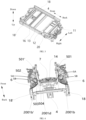
- a vehicle 100 according to an embodiment of the present disclosure is described with reference to FIG. 1 to FIG. 18 .
- the vehicle 100 includes an underbody 1, a front subframe 3, and a battery pack 2.
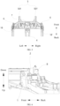
- An X direction is a length direction of the vehicle 100, namely, a front-rear direction.
- a Y direction is a width direction of the vehicle 100, namely, a left-right direction.
- a Z direction is a height direction of the vehicle 100, namely, an up-down direction.
- the front subframe 3 is connected to the underbody 1, and the battery pack 2 is connected to the underbody 1 and arranged on a lower side of the underbody 1.
- a rear end surface 31 of the front subframe 3 forms a limiting surface for forward extension of the battery pack 2.
- the battery pack 2 may extend to the rear end surface 31 of the front subframe 3.
- the battery pack 2 can also serve as a force transmission structure for force transmission in addition to force transmission of a front longitudinal beam 5.
- the rear end surface 31 of the front subframe 3 forms the limiting surface for forward extension of the battery pack 2, so that when the vehicle 100 normally travels, the rear end surface 31 of the front subframe 2 is spaced apart from a front end surface 21 of the battery pack 2. If a collision occurs at the front of the vehicle 100, the front subframe 2 receives a force and moves backward to contact with the front end surface 21 of the battery pack 2, causing the battery pack 2 to participate in the force transmission. Therefore, the battery pack 2 can resist and distribute the force, to improve safety performance of the vehicle 100.
- a floor of a vehicle body is generally of a metal plate structure, and is an important component for bearing and sealing of a passenger compartment.
- An upper housing of a battery pack is generally made of aluminum.
- the battery pack is fixedly mounted below the floor of a vehicle body.
- the floor of the vehicle body and the battery pack are designed individually as two different components. In this case, an assembly gap needs to be reserved between the floor of the vehicle body and the battery pack in the Z direction, leading to low space utilization and a relatively high height of the whole vehicle.
- the arrangement of the floor of the vehicle body in the related art may be omitted, and at least a part of an upper surface of the battery pack 2 is used to form the floor of the vehicle body.
- the floor of the vehicle body may be a front floor of the vehicle body, increasing the space utilization and passenger space of the vehicle 100, lowering the height of the whole vehicle, and improving mobility performance of the vehicle 100.
- a structure of the vehicle 100 is simplified, and assembly efficiency is improved.
- the rear end surface 31 of the front subframe 3 forms the limiting surface for forward extension of the battery pack 2, so that a dimension of the battery pack 2 in the front-rear direction can be increased, the space utilization of the vehicle 100 can be increased, and the battery pack 2 can serve as the force transmission structure for force transmission, to improve the safety performance of the vehicle 100.
- the at least a part of the upper surface of the battery pack 2 forms the floor of the vehicle body, so that a height of the whole vehicle can be lowered, and the space utilization and the passenger space of the vehicle 100 can be increased.
- a minimum distance between the front end surface 21 of the battery pack 2 and the rear end surface 31 of the front subframe 3 is d 1 , where d 1 satisfies: 10 mm ⁇ d 1 ⁇ 100 mm.
- d 1 50 mm.
- the rear end surface 31 of the front subframe 3 is not directly connected to and is spaced apart from the battery pack 2, so that the battery pack 2 can be conveniently mounted, an assembly speed of the vehicle 100 is increased, and interference between the front end surface 21 of the battery pack 2 and the rear end surface 31 of the front subframe 3 when being mounted or when the vehicle 100 travels is avoided.
- the underbody 1 further includes a left rocker rail 18 and a right rocker rail 18' oppositely arranged in the width direction of the vehicle body.
- the battery pack 2 is connected to the left rocker rail 18 and the right rocker rail 18' to cause the left rocker rail 18 and the right rocker rail 18' to form a battery pack mounting beam.
- the battery pack mounting beam is used for mounting the battery pack, and two battery pack mounting beams are provided, and are respectively arranged between the battery pack and the left rocker rail and between the battery pack and the right rocker rail in the Y direction.
- the battery pack mounting beams With the battery pack mounting beams arranged in this way, placement space for the battery pack in the width direction of the vehicle is small, and it is not conducive to arrangement of a large size battery pack. In addition, when a side collision occurs on the vehicle, the battery pack mounting beams cannot well combine force transmissions of the battery pack, the left rocker rail, and the right rocker rail.
- the battery pack 2 extends toward two sides in the Y direction and is directly connected to the left rocker rail 18 and the right rocker rail 18'. Space for accommodating the battery pack 2 between a left side surface of the right rocker rail 18' and a right side surface of the left rocker rail 18 increases, facilitating a design of a large dimension of the battery pack 2 in the left-right direction.
- the dimension of the battery pack 2 in the Y direction can be increased, so that an electrical capacity of the battery pack 2 is increased, and endurance of the vehicle 100 is improved.
- the battery pack 2 can participate in force transmission, to improve the safety performance of the vehicle 100. During a side collision of the vehicle 100, when the left rocker rail 18 and the right rocker rail 18' receive a force, the battery pack 2 participates in collision force transmission, to improve the safety performance of the vehicle 100.
- the underbody 1 includes a left rocker rail 18 and a right rocker rail 18' oppositely arranged in the width direction of the vehicle body.
- the front end surface 21 of the battery pack 2 extends beyond a front end surface of the left rocker rail 18 and a front end surface of the right rocker rail 18' in the length direction of the vehicle 100. In this way, a dimension of the battery pack 2 in the X direction is relatively large, and can facilitate the force transmission with the front subframe 3.
- the front end surface 21 of the battery pack 2 may alternatively be flush with the front end surface of the left rocker rail 18 and the front end surface of the right rocker rail 18' in the length direction of the vehicle 100, which is not limited herein.
- the underbody 1 includes a front cross beam 7, and a left rocker rail 18 and a right rocker rail 18' oppositely arranged in the width direction of the vehicle body.
- An extending length of the front cross beam 7 in the width direction of the vehicle body is greater than a distance from an inner surface of the left rocker rail 18 to an inner surface of the right rocker rail 18'.
- the "inner surface of the left rocker rail 18" is a surface of a right side of the left rocker rail 18, and the "inner surface of the right rocker rail 18′′′ is a surface of a left side of the right rocker rail 18'.
- the left front rocker rail 18 and the right front rocker rail 18' may participate in the force transmission when a front collision occurs on the vehicle 100, to improve the safety performance of the vehicle 100.
- the left front rocker rail 18 and the right front rocker rail 18' may be respectively arranged on a left side and a right side of the battery pack 2 to protect the battery pack 2.
- the left front rocker rail 18, the battery pack 2, and the right front rocker rail 18' may participate in the force transmission when the side collision occurs on the vehicle 100, to improve the safety performance.
- the underbody 1 further includes a front cross beam 7 and oppositely arranged A-pillars 6. Two ends of the front cross beam 7 are connected to the A-pillars 6. Therefore, when a front collision occurs on the vehicle 100, a force transmitted to the front cross beam 7 can be transmitted to the A-pillars 6 through the left and right ends of the front cross beam 7, thereby improving a force-bearing capability of a front end of the vehicle 100 and improving the safety of the vehicle 100.
- the two A-pillars 6 are respectively arranged on a left side and a right side of the underbody 1, so that a collision force received by the vehicle 100 when a collision occurs on a left or right side of the vehicle 100 can be relieved, a force-bearing capability of the underbody 1 can be improved, and safety of the vehicle 100 is improved.
- the underbody 1 further includes a front longitudinal beam 5.
- the front longitudinal beam 5 is connected to the front cross beam 7, to transmit the front collision force to the front cross beam 7 through the front longitudinal beam 5.
- the front longitudinal beam 5 may include a left-front longitudinal beam 501 and a right-front longitudinal beam 501'.
- the left-front longitudinal beam 501 and the right-front longitudinal beam 501' may be arranged at two ends of a front side of the front cross beam 7, and are connected to the front cross beam 7.
- a force transmitted to the front longitudinal beam 5 may be transmitted to the front cross beam 7 through an end of the front longitudinal beam 5 connected to the front cross beam 7, and the front collision force is transmitted toward a width direction of a vehicle cross beam through the cross beam 7.
- the front collision force received by the vehicle 100 when a collision occurs on the front side is relieved, structural stability of the vehicle 100 can be enhanced, a force-bearing capability of the front end of the vehicle 100 can be improved, and the safety performance of the vehicle 100 is improved.
- a rear side of the front longitudinal beam 5 includes an upper-side force transmission structure 5A and a lower-side force transmission structure 5B.
- a rear end of the upper-side force transmission structure 5A is connected to the front cross beam 7, and a rear end bottom surface of the lower-side force transmission structure 5B is spaced apart from the battery pack 2 in a vertical direction to form a sealed gap.
- the "sealed gap” means that the upper surface of the battery pack 2 hermetically fits with and forms a gap with a bottom surface of the underbody 1.
- the rear end of the upper-side force transmission structure 5A of the front longitudinal beam 5 is connected (for example, lap-connected) to the front cross beam 7.
- a part of the collision force transmitted to the front longitudinal beam 5 may be transmitted to the front cross beam 7 through the connection between the rear end of the upper-side force transmission structure 5A of the front longitudinal beam 5 and the front cross beam 7, and the front collision force is transmitted toward two sides of the vehicle 100 in the width direction through the front cross beam 7; and another part of the front collision force transmitted to the front longitudinal beam 5 may be transmitted backward through the rear end of the lower-side force transmission structure 5B of the front longitudinal beam 5, so that the front collision force on the front side of the vehicle 100 during collision is relieved, the structural stability of the vehicle 100 can be enhanced, and the force-bearing capability of the front end of the vehicle 100 is improved, thereby improving the safety of the vehicle 100.
- a rear end bottom surface of the lower-side force transmission structure 5B of the front longitudinal beam 5 is parallel to a top surface of the battery pack 2, so that a sealing member can be conveniently arranged between the rear end bottom surface of the lower-side force transmission structure 5B and the battery pack 2.
- a rear end bottom surface of the front longitudinal beam 5 is arranged parallel to the top surface of the battery pack 2, and is spaced apart from the top surface of the battery pack 2 in the vertical direction to form a sealed gap.
- a sealed structure may be arranged between a lower side of the front longitudinal beam 5 and the top surface of the battery pack 2.
- the rear end bottom surface of the front longitudinal beam 5 does not interfere with the top surface of the battery pack 2, to prevent the rear end bottom surface of the front longitudinal beam 5 from hindering mounting of the battery pack 2.
- a mounting position of the battery pack 2 can be raised, so that a chassis height of the vehicle 100 is raised, and the mobility of the vehicle 100 is improved, thereby lowering the height of the whole vehicle, and increasing space inside the vehicle.
- force transmission of the front longitudinal beam 5 toward the two sides in the width direction is facilitated, thereby facilitating transmission and distribution of the force, and improving the safety performance of the vehicle 100.
- the underbody 1 further includes a front longitudinal beam 5.
- the rear end bottom surface of the front longitudinal beam 5 is spaced apart from the top surface of the battery pack 2 in the vertical direction to form a sealed gap. Space between the rear end bottom surface of the front longitudinal beam 5 and the top surface of the battery pack 2 is suitable for arrangement of a sealed structure.
- the rear end bottom surface of the front longitudinal beam 5 does not interfere with the top surface of the battery pack 2, to prevent the rear end bottom surface of the front longitudinal beam 5 from hindering the mounting of the battery pack 2.
- the mounting position of the battery pack 2 can be raised, so that the chassis height of the vehicle 100 is raised, and the mobility of the vehicle 100 is improved. Moreover, force transmission is facilitated.
- the rear end bottom surface of the front longitudinal beam 5 is parallel to the top surface of the battery pack 2, so that a sealing member can be conveniently arranged between the rear end bottom surface of the front longitudinal beam 5 and the battery pack 2.
- the lower-side force transmission structure 5B is connected to the left rocker rail 18, the right rocker rail 18, and a central channel 4.
- the front longitudinal beam 5 may include a left-front longitudinal beam 501 and a right-front longitudinal beam 501'.
- a lower end of the left-front longitudinal beam 501 is connected to the left rocker rail 18, a lower end of the right-front longitudinal beam 501' is connected to a left side of the right rocker rail 18', and at least a part of the left-front longitudinal beam 501 and the right-front longitudinal beam 501' may be connected to the central channel 4.
- a part of the front collision force may be transmitted to the left rocker rail 18 and the right rocker rail 18' respectively through the left-front longitudinal beam 501 and the right-front longitudinal beam 501', and transmitted toward the length direction of the vehicle 100 through the left rocker rail 18 and the right rocker rail 18'.
- Another part of the front collision force may be transmitted toward the central channel 4 through lower ends of the left-front longitudinal beam 501 and the right-front longitudinal beam 501'.
- At least a part of the side collision force may be transmitted to the battery pack 2 through the left rocker rail 18 and the right-front longitudinal beam 501' when a collision occurs on the left side or the right side of the vehicle 100.
- the underbody 1 may include a front-seat front cross beam 16.
- a left end and a right end of the front-seat front cross beam 16 are respectively connected to a right side of the left rocker rail 18 and a left side of the right rocker rail 18'.
- a front side of the front-seat front cross beam 16 may be connected to a rear end of the central channel 4.
- a part of the front collision force, when transmitted to the rear end of the central channel 4 may be transmitted toward the width direction of the vehicle 100 through the front-seat front cross beam 16, so that the force received by the vehicle 100 when a collision occurs on the front side of the vehicle 100 is relieved, thereby improving the force-bearing capability of the vehicle 100, and improving the safety of the vehicle 100.
- the lower-side force transmission structure 5B is a Y-shaped structure.
- Both front longitudinal beams 501 and 501' include: a first connecting section 502, a second connecting section 503, and a third connecting section 504.
- a rear end of the first connecting section 502 is connected to both a front end of the second connecting section 503 and a front end of the third connecting section 504.
- the front end of the second connecting section 503 is connected to the front end of the third connecting section 504, and a rear end of the second connecting section 503 gradually extends away from a rear end of the third connecting section 504. That is, the first connecting section 502, the second connecting section 503, and the third connecting section 504 can jointly form a Y-shaped structure.
- the second connecting section 503 is located on an outer side of the third connecting section 504, the second connecting section 503 is connected to the A-pillar 6, and a bottom surface of the second connecting section 503 and a bottom surface of the third connecting section 504 are located on a same plane, to facilitate the transmission and the distribution of the forces on the left side and the right side.
- the bottom surface of the second connecting section 503 and the bottom surface of the third connecting section 504 are adapted to be parallel to the battery pack 2, so that the battery pack 2 can extend to the bottom surface of the second connecting section 503 and the bottom surface of the third connecting section 504.
- the bottom surface of the second connecting section 503 may have at least one mounting point (not shown).
- the front end surface 21 of the battery pack 2 may extend to the mounting point in the second connecting section 503 and be fixedly connected to the front longitudinal beam 5 through the mounting point, so that the battery pack 2 can participate in the force transmission, thereby relieving the force received by the vehicle 100 when a collision occurs on the front side of the vehicle 100, improving the force-bearing capability of the vehicle 100, and ensuring that the safety of the vehicle 100 is improved.
- a left end of the lower-side force transmission structure 5B of the left-front longitudinal beam 501 may be connected to the A-pillar 6 on the left side of the underbody 1.
- a right end of the lower-side force transmission structure 5B of the right-front longitudinal beam 501' may be connected to the A-pillar 6 on the right side of the underbody 1.
- the lower-side force transmission structure 5B of the front longitudinal beam 5 is connected to the A-pillar 6 arranged on the underbody 1, so that the front collision force is transmitted to the A-pillar 6, the force received by the vehicle 100 when a collision occurs on the front side of the vehicle 100 is relieved, the force-bearing capability of the vehicle 100 is improved, and it is ensured that the safety of the vehicle 100 is improved.
- the front longitudinal beam 5 includes a left-front longitudinal beam 501 and a right-front longitudinal beam 501' spaced apart in the left-right direction of the vehicle 100.
- a bottom cross beam 14 is connected between the left-front longitudinal beam 501 and the right-front longitudinal beam 501'.
- a bottom surface of the bottom cross beam 14 is spaced apart from the top surface of the battery pack 2 in the vertical direction to form a gap, to reserve a sealed space, and prevent the bottom cross beam 14 from blocking the battery pack 2 from extending forward, so that the electrical capacity of the battery pack is increased.
- the bottom cross beam 14 may be arranged on a rear side of the left-front longitudinal beam 501 and the right-front longitudinal beam 501', and two ends of the bottom cross beam 14 may be respectively connected to the left-front longitudinal beam 501 and the right-front longitudinal beam 501'.
- the bottom surface of the bottom cross beam 14 is spaced apart from the top surface of the battery pack 2 in the vertical direction to form the gap. Through this arrangement, the bottom surface of the bottom cross beam 14 does not interfere with the top surface of the battery pack 2, so that the front end of the battery pack 2 can continue to extend forward, the mounting space for the battery pack 2 in the X direction can be enlarged, and hindering of the mounting of the battery pack 2 by the bottom surface of the bottom cross beam 14 is avoided, thereby improving the assembly speed of the vehicle 100, facilitating automated production of the vehicle 100, raising the chassis height of the vehicle 100, and improving the mobility of the vehicle 100.
- the rear end bottom surface of the front longitudinal beam 5 is parallel to the top surface of the battery pack 2, so that a sealing member can be conveniently arranged between the rear end bottom surface of the front longitudinal beam 5 and the battery pack 2.
- the vehicle 100 further includes a rear subframe 8.
- the rear subframe 8 is connected to the underbody 1.
- a front end surface of the rear subframe 8 forms a limiting surface for backward extension of the battery pack 2.
- the battery pack 2 may extend to the front end surface of the rear subframe 8.
- the battery pack 2 can also serve as a force transmission structure for force transmission in addition to force transmission of the front longitudinal beam 5.
- the front end surface of the rear subframe 8 forms the limiting surface for backward extension of the battery pack 2. When the vehicle 100 normally travels, the front end surface of the rear subframe 8 is spaced apart from the rear end surface of the battery pack 2.
- the rear subframe 8 receives a force and moves forward to contact with the rear end surface of the battery pack 2, causing the battery pack 2 to participate in the force transmission. Therefore, the battery pack 2 can resist and distribute the force, to improve the safety performance of the vehicle 100.
- the dimension of the battery pack 2 in the X direction can be increased, the space utilization can be increased, and the endurance of the vehicle 100 is improved.
- the battery pack 2 can resist and distribute the force, to improve the safety performance of the vehicle 100.
- a minimum distance between a front surface of the rear subframe 8 and a rear surface of the battery pack 2 is d 2 , where d 2 satisfies: 15 mm ⁇ d 2 ⁇ 30 mm.
- d 2 20 mm.
- the front surface of the rear subframe 8 is not directly connected to and is spaced apart from the battery pack 2, so that the battery pack 2 can be conveniently mounted, the assembly speed of the vehicle 100 is increased, and interference between the rear end surface of the battery pack 2 and the front surface of the rear subframe 8 when being mounted or when the vehicle 100 travels is avoided.
- the underbody 1 further includes a middle cross beam 11 and two rear longitudinal beams 9 spaced apart.
- the middle cross beam 11 extends in the width direction of the vehicle 100, and is connected to the rear longitudinal beams 9 and the left rocker rail 18 and the right rocker rail 18'.
- the middle cross beam 11 is arranged on a rear side of the underbody 1. Two ends of the middle cross beam 11 extending in the width direction of the vehicle 100 are respectively connected to the left rocker rail 18 and the right rocker rail 18', and at least a part of a rear side of the middle cross beam 11 may be located below a front end of the rear longitudinal beam 9.
- the left rocker rail 18 and the right rocker rail 18' may extend to the middle cross beam 11.
- the left rocker rail 18 and the right rocker rail 18' can participate in the force transmission when a rear collision occurs on the vehicle 100, to improve the safety performance of the vehicle 100.
- the left rocker rail 18 and the right rocker rail 18' may be respectively arranged on the left side and the right side of the battery pack 2 to protect the battery pack 2.
- the left rocker rail 18, the battery pack 2, and the right rocker rail 18' may participate in the force transmission when a side collision occurs on the vehicle 100, to improve the safety performance.
- the middle cross beam 11 forms the battery pack mounting beam.
- the rear end of the battery pack 2 may be mounted on the middle cross beam 11.
- a lower surface of the middle cross beam 11 is spaced apart from the top surface of the battery pack 2 in the vertical direction to form a sealed gap. Space between the lower surface of the middle cross beam 11 and the top surface of the battery pack 2 is suitable for arrangement of a sealed structure. Through this arrangement, the lower surface of the middle cross beam 11 does not interfere with the top surface of the battery pack 2, to prevent the lower surface of the middle cross beam 11 from hindering the mounting of the battery pack 2.
- the dimension of the battery pack 2 in the X direction can be increased, so that the chassis height of the vehicle 100 is raised, and the mobility of the vehicle 100 is improved.
- the lower surface of the middle cross beam 11 is parallel to the top surface of the battery pack 2, so that a sealing member can be conveniently arranged between the lower surface of the middle cross beam 11 and the battery pack 2.
- subframe mounting bases 15 are arranged at intervals on the middle cross beam 11.
- the subframe mounting bases 15 are arranged on a rear side of a rear end surface of the rocker rails (namely, the left rocker rail 18 and the right rocker rail 18') in the length direction of the vehicle 100. Therefore, the subframe mounting bases 15 may form a cage structure.
- the subframe mounting bases 15 at least surround a periphery in a left-right direction of a rear portion of the battery pack 2, to protect a side edge of the rear portion of the battery pack 2.
- an upper surface of the rear portion of the battery pack 2 is spaced apart from the subframe mounting bases 15 in a height direction, so that other components can be accommodated at the spacing, thereby making proper use of space.
- the subframe mounting bases 15 are arranged on a rear side of the connection between the middle cross beam 11 and the battery pack 20. With the subframe mounting bases 15 arranged in this way, the collision force received by the subframe can be transmitted to the subframe mounting bases 15, then to the middle cross beam 11 and to the battery pack 20, so that an effective force transmission path can be formed, and a new force transmission path can be formed by using the battery pack 20 and the middle cross beam 11.
- damage to the vehicle structure during the force transmission can be effectively reduced.
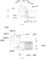
- the left rocker rail 18 includes a left sill housing 1801 and a left sill reinforcing beam 1802 arranged in the left sill housing 1801, and the right rocker rail 18' includes a right sill housing (not shown) and a right sill reinforcing beam (not shown) arranged in the right sill housing.
- the left rocker rail 18 is used as an example for description below.
- the left rocker rail 18 is arranged on the left side of the underbody 1 and extends in the length direction of the vehicle 100.
- the left rocker rail 18 includes a left sill housing 1801 and a left sill reinforcing beam 1802 arranged in the left sill housing 1801.
- the left sill housing 1801 may include a left housing 18011 of the left sill and a right housing 18011' of the left sill.
- the left sill reinforcing beam 1802 may have at least one cavity 18021 running through the left sill reinforcing beam 1802 in the front-rear direction, and the left sill reinforcing beam 1802 is arranged in an accommodating cavity jointly formed by the left housing 18011 of the left sill and the right housing 18011' of the left sill.
- An upper surface of the left housing 18011 of the left sill is provided with an upper left bent edge 18012', a lower surface of the left housing 18011 of the left sill is provided with a lower left bent edge 18013', an upper surface of the right housing 18011' of the left sill is provided with an upper right bent edge 18012, and a lower surface of the right housing 18011' of the left sill is provided with a lower right bent edge 18013.
- the upper left bent edge 18012' and the upper right bent edge 18012 are fittingly arranged in the width direction, and the lower left bent edge 18013' and the lower right bent edge 18013 are fittingly arranged in the width direction, to improve structural stability of the left rocker rail 18, and improve a force-bearing capability of the left sill housing 1801.
- the left sill reinforcing beam 1802 is arranged in the left sill housing 1801. At least a part of the left sill reinforcing beam 1802 may be connected to at least one of the left housing 18011 of the left sill and the right housing 18011' of the left sill.
- the left sill reinforcing beam 1802 arranged in this way can improve a force-bearing capability of the left rocker rail 18, so that when a collision occurs on the left side of the vehicle 100, the left sill reinforcing beam 1802 can protect the underbody 1, thereby improving the safety of the vehicle 100.
- Multiple cavities 18021 may be provided.
- the multiple cavities 18021 run through the left sill reinforcing beam 1802 in the front-rear direction.
- a cross section of the multiple cavities 18021 in the front-rear direction may be in a grid shape.
- the left sill reinforcing beam 1802 arranged in this way can reduce the material consumption and weight of the left sill reinforcing beam 1802, so that a lightweight design of the vehicle 100 is easy to be achieved.
- the rocker rails may achieve a "sandwich" side protection structure including an upper layer, a middle layer, and a lower layer.
- the left rocker rail 18 is used as an example, after the left rocker rail 18 receives a force, the left rocker rail 18 may provide an upper-layer force transmission through the upper housing 2011 of the battery pack in an upper portion of the battery pack 2; the force is transmitted from the left sill reinforcing beam 1802 to the left extension portion 20111 and then to the battery cell 202, so that a middle-layer side force transmission structure is formed; and the force is transmitted from the left rocker rail 18 to the left extension portion 20111 and the battery cell 202 and then to a bottom plate of the battery pack 2, so that a lower-layer side force transmission structure is formed. Therefore, the "sandwich" side protection structure including an upper layer, a middle layer, and a lower layer is formed, and passengers in the vehicle can be better protected.
- the left sill reinforcing beam 1802 and the right sill reinforcing beam are each made of an aluminum alloy profile.
- the left sill reinforcing beam 1802 and the right sill reinforcing beam are configured to be made of aluminum alloy profiles, rigidity, torsional strength, and force-bearing capabilities of the left sill reinforcing beam 1802 and the right sill reinforcing beam can be ensured, weights of the left sill reinforcing beam 1802 and the right sill reinforcing beam are reduced, and a lightweight design of the vehicle 100 is easy to be achieved.
- the left sill reinforcing beam 1802 and the right sill reinforcing beam well fit with the battery pack 2, thereby achieving a good force transmission effect.
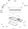
- the battery pack 2 includes an upper housing 2011 of the battery pack, a lower housing 2012 of the battery pack, and at least one battery cell 202.
- the upper housing 2011 of the battery pack and the lower housing 2012 of the battery pack form an accommodating space 2013, and the at least one battery cell 202 is arranged in the accommodating space 2013.
- At least a part of an upper surface of the upper housing 2011 of the battery pack forms the floor of the vehicle body. Therefore, at least a part of the floor of the vehicle body in the related art can be omitted in the present disclosure.
- the arrangement of the floor of the vehicle body in the related art is omitted, and the at least a part of the upper surface of the battery pack 2 is used to form the floor of the vehicle body, so that the space utilization of the vehicle 100 is improved, the passenger space is enlarged, the height of the whole vehicle is lowered, and the mobility of the vehicle 100 is improved.
- the structure of the vehicle 100 can be simplified, and the assembly efficiency can be improved.
- Two sides of the upper housing 2011 of the battery pack in the width direction may respectively have a left extension portion 20111 and a right extension portion 20111'.
- Multiple left connecting holes may be provided at intervals on the left extension portion 20111 in the length direction of the vehicle 100, and multiple right connecting holes (not shown) may be provided at intervals on the right extension portion 20111' in the length direction of the vehicle 100.
- the left connecting holes and the right connecting holes may be in communication in an up-down direction.
- a connecting bolt 19 may be arranged in each of the left connecting holes and right connecting holes.
- the upper housing 2011 of the battery pack may be connected to the left rocker rail 18 and the right rocker rail 18' through the connecting bolts 19.
- Connection between the left extension portion 20111 and the left rocker rail 18 is used as an example for description below.
- Left sill connecting holes (not shown) running through in the up-down direction may be provided at positions corresponding to the left connecting holes on the left sill housing 1801 of the left rocker rail 18.
- the connecting bolts 19 can run through the left sill connecting holes of the left sill housing 1801 and the left connecting holes of the left extension portion 20111, to improve the stability of connection between the left rocker rail 18 and the upper housing 2011 of the battery pack.
- the battery pack 2 may be used as a force-bearing component, so that when a collision occurs on the left side of the vehicle 100, the side collision force may be transmitted from the left rocker rail 18 to the battery pack 2, to relieve the force received by the vehicle 100 when a collision occurs on the left side of the vehicle 100, and prevent the vehicle 100 from greatly deforming due to the side collision force, so that the force-bearing capability of the vehicle 100 is improved, and the safety of the vehicle 100 is improved.
- the accommodating space 2013 that can accommodate the at least one battery cell 202 is formed between the upper housing 2011 of the battery pack and the lower housing 2012 of the battery pack.
- the upper housing 2011 of the battery pack and the lower housing 2012 of the battery pack can jointly protect the battery cell 202, thereby increasing a quantity of the battery cells 202 accommodated in the battery pack 2, increasing a total electrical capacity of the battery pack 2, and improving the endurance of the vehicle 100.
- the at least a part of the upper surface of the upper housing 2011 of the battery pack forms the floor of the vehicle body, so that the accommodating space 2013 of the battery pack 2 can extend upward, thereby enlarging the mounting space for the battery pack 2, increasing the capacity of the battery pack 2. Therefore, the electrical capacity of the battery pack 2 is improved, the endurance of the vehicle 100 is improved, material consumption is reduced, the total weight of the vehicle 100 is reduced, and a lightweight design of the vehicle 100 is easy to be achieved.
- the battery cell 202 is fixedly connected to the upper housing 2011 of the battery pack. Therefore, space occupied by the battery pack 2 in the Z direction can be reduced, the space utilization in the Z direction is improved, and mounting reliability between the battery cell 202 and the upper housing 2011 of the battery pack is improved. As shown in FIG. 11 and FIG. 12 , a top surface of the battery cell 202 is bonded with an upper cover through a structural adhesive 203.
- the space occupied by the battery pack 2 in the Z direction can be reduced, and a gap between the battery cell 202 and the upper housing 2011 of the battery pack can be reduced, to improve compactness between the battery cell 202 and the upper housing 2011 of the battery pack, thereby preventing a case in which the gap between the battery cell 202 and the upper housing 2011 of the battery pack is relatively large, and when the upper housing 2011 of the battery pack is used as the floor of the vehicle body, the battery cell 202 is subjected to a relatively large force, so that the battery cell 202 falls off the upper housing 2011 of the battery pack.
- the upper housing 2011 of the battery pack can provide force transmission, so that strength of the upper housing 2011 of the battery pack is improved, and modality of the upper housing 2011 of the battery pack is enhanced.
- the lower housing 2012 of the battery pack is a cooling plate, and a bottom surface of the battery cell 202 is bonded with the lower housing 2012 of the battery pack through a thermal adhesive 204.
- the cooling plate of the battery pack 2 serving as the lower housing, has a cooling effect on the battery cell 202.
- the bottom surface of the battery cell 202 is bonded with the lower housing 2012 of the battery pack through the thermal adhesive 204.
- the lower housing 2012 of the battery pack With the lower housing 2012 of the battery pack arranged in this way, when the battery cell 202 produces heat, the heat can be conducted from the bottom surface of the battery cell 202 to the lower housing 2012 of the battery cell through the thermal adhesive 204 for cooling, so that temperature in the battery pack 2 is reduced, and danger caused by over-temperature of the battery cell 202 in the battery pack 2 is avoided, thereby improving safety and reliability of the battery pack 2, and improving the safety of the vehicle 100. Moreover, an integration degree of the battery pack 2 is improved, and energy density of the battery pack 2 is improved.
- the lower housing 2012 of the battery pack can be replaced with the cooling plate, so that the lower housing 2012 of the battery pack is not necessary, and the weight of the battery pack 2 is reduced.
- the cooling plate can further protect the battery pack 2, thereby improving the safety and the reliability of the battery pack 2, and improving the safety of the vehicle 100.
- the battery pack 2 may include at least one battery cell 202.
- a length direction of the battery cell 202 is the length direction of the vehicle 100.
- the at least one battery cell 202 is arranged in the accommodating space 2013 of the battery pack 2.
- the length direction of the battery cell 202 being set as the length direction of the vehicle 100, a quantity of battery cells 202 arranged in the width direction can be increased, and the space utilization of the battery pack 2 can be increased.
- the quantity of battery cells 202 accommodated in the battery pack 2 is increased, so that the endurance of the vehicle 100 is improved.
- the battery pack 2 includes multiple battery cells 202.
- the multiple battery cells 202 are arranged side by side in the width direction of the vehicle 100.
- a main expansion surface of the battery cell 202 (namely, an outer surface with a largest area of the battery cell 202) is arranged facing the width direction of the vehicle 100, which is convenient for the battery cell 202 to participate in the force transmission during a side collision on the vehicle 100; and is convenient to improve the space utilization of the battery pack 2, and increases the quantity of battery cells 202 accommodated in the battery pack 2, so that the total electrical capacity of the battery pack 2 is improved, thereby improving the endurance of the vehicle 100.
- the main expansion surface of the battery cell 202 closely fits with the upper housing 2011 of the battery pack.
- the battery cell 202 arranged in this way can enlarge a force transmission area, thereby reducing pressure, to improve the force transmission effect.
- a sealing plate assembly 20 is arranged on the underbody 1, and the upper surface of the battery pack 2 is hermetically connected to the sealing plate assembly 20. Therefore, the sealing reliability between the battery pack 2 and the passenger compartment can be improved, thereby preventing impurities such as dust from entering the lower side of the underbody 1 from the upper surface of the battery pack 2.
- the sealing plate assembly 20 is arranged on the vehicle body, and a gap between the sealing plate assembly 20 and the battery pack 2 is a sealed gap.
- the sealing plate assembly can provide a flat plane to facilitate sealing with the battery pack 2.
- the sealing plate assembly 20 arranged in this way can conveniently seal the upper side of the battery pack 2, ensuring the sealing reliability and facilitating assembly of the vehicle.
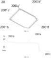
- the sealing plate assembly 20 includes an annular sealing plate 2001 and at least one sealing member 2002.
- the at least one sealing member 2002 is arranged between the sealing plate 2001 and the battery pack 2.
- the at least one sealing member 2002 may be configured to be in an annular shape, and two such sealing members may be provided.
- the two sealing members 2002 are sealed between the sealing plate 2001 and the battery pack 2.
- One of two adjacent sealing members 2002 is located at a periphery of the other sealing member 2002, and the two sealing members 2002 are spaced apart in an inner-outer direction.
- the at least one sealing member 2002 may be, for example, a sealing sponge, or a sealing rubber strip.
- the two sealing members 2002 deform after receiving stress, implementing the sealing reliability.
- a fitting degree of a single sealing member 2002 is improved, to improve a sealing effect of the sealing plate 2001, and block substances such as water and air inside and outside a rubber strip.
- the sealing plate 2001 may include multiple sub-sealing plates 2001 connected in sequence, and the multiple sub-sealing plates 2001 may be welded; or the sealing plate 2001 may be made by stamping a whole steel plate, thereby improving sealing performance of the sealing plate 2001 through integral forming.
- the sealing plate 2001 includes a first plane portion 2001a
- the battery pack 2 includes a second plane portion 2014.
- the first plane portion 2001a is opposite to the second plane portion 2014
- the at least one sealing member 2002 is arranged between the first plane portion 2001a and the second plane portion 2014.
- the first plane portion 2001a is arranged opposite to the second plane portion 2014
- the least one sealing member 2002 is fittingly arranged between the first plane portion 2001a and the second plane portion 2014, thereby further improving the sealing effect of the sealing plate 2001, improving sealability of the underbody 1, and improving passenger comfort.
- the at least one sealing member 2002 is a foam member.
- the foam member may be made of an ethylene vinyl acetate (EVA) or an expandable polyethylene (EPE) material.
- EVA ethylene vinyl acetate
- EPE expandable polyethylene
- the foam member has characteristics such as light weight, deformability, good sound insulation, good heat insulation, and the like, which can improve heat insulation of the sealing plate 2001, and prevent upward transfer of the temperature after the battery pack 2 heats up, so that the safety and the reliability of the battery pack 2 are improved, and the safety of the vehicle 100 is improved.
- the foam member can improve the sound insulation of the vehicle 100, and block substances such as water and air, to improve the passenger comfort.
- the foam member may have a specific amount of sealing compression, to ensure the sealing effect.
- the foam member may be bonded with the battery pack 2.
- a left rocker rail 18 is arranged on a left side of the underbody 1, and a right rocker rail 18' is arranged on a right side of the underbody 1.
- the sealing plate 2001 includes a left sealing plate section 2001b and a right sealing plate section 2001b'.
- the left sealing plate section 2001b includes a first plane portion 2001a.
- a left end of the left sealing plate section 2001b is provided with a left bent edge 2001c.
- the first plane portion 2001a of the left sealing plate section 2001b is connected to the left bent edge 2001c, and the left sealing plate section 2001b is connected to the left rocker rail 18 through the left bent edge 2001c.
- the right sealing plate section 2001b' includes a first plane portion 2001a.
- a right end of the right sealing plate section 2001b' is provided with a right bent edge 2001c'.
- the first plane portion 2001a of the right sealing plate section 2001b is connected to the right bent edge 2001c', and the right sealing plate section 2001b' is connected to the right rocker rail 18' through the right bent edge 2001c'.
- the left sealing plate section 2001b is connected to the left rocker rail 18 through the left bent edge 2001c, and the right sealing plate section 2001b' is connected to the right rocker rail 18' through the right bent edge 2001c'.
- connection between the left rocker rail 18 and the left sealing plate section 2001b is used as an example for description below.
- the left end of the left sealing plate section 2001b is provided with the left bent edge 2001c bending and extending downward.
- a left side surface of the left bent edge 2001c may be arranged opposite to the right side surface of the left rocker rail 18, and the left side surface of the left bent edge 2001c may be at least partially connected to the right side surface of the left rocker rail 18.
- the sealing plate 2001 further includes a front sealing plate section 2001d and a rear sealing plate section 2001f.
- the front sealing plate section 2001d is connected to the front longitudinal beam 5, and the rear sealing plate section 2001f is connected to the middle cross beam 11.
- the sealing plate 2001 may include the front sealing plate section 2001d and the rear sealing plate section 2001f.
- a front bent edge 2001e may be arranged on at least one side of the front sealing plate section 2001d in the width direction.
- the front sealing plate section 2001d is connected to the front longitudinal beam 5 of the underbody 1 through the front bent edge 2001e.
- a rear bent edge (not shown) may be arranged on at least one side of the rear sealing plate section 2001f in the width direction.
- the rear sealing plate section 2001f is connected to the middle cross beam 11 of the underbody 1 through the rear bent edge.
- a seat cross beam 13 extending in the width direction is arranged on the underbody 1.
- a battery pack reinforcing beam 2015 extending in the width direction is arranged on the battery pack 2.
- the battery pack 2 is connected to the seat cross beam 13 through the battery pack reinforcing beam 2015.
- the seat cross beam 13 extending in the width direction may be arranged on the underbody 1.
- a seat is adapted to be arranged on an upper side of the seat cross beam 13.
- the battery pack reinforcing beam 2015 extending in the width direction may be arranged at a position corresponding to the seat cross beam 13 on the battery pack 2.
- the battery pack 2 is connected to the seat cross beam 13 through the battery pack reinforcing beam 2015, so that connection reliability between the battery pack 2 and the underbody 1 can be improved, and the safety of the vehicle is improved.
- the side collision force can be transmitted in the width direction of the vehicle through the battery pack reinforcing beam 2015, to reduce an impact of the side collision force is reduced, and prevent the vehicle 100 from greatly deforming due to the side collision force, thereby improving the force-bearing capability of the vehicle 100, and improving the safety of the vehicle 100.
- An annular edge of the upper surface of the battery pack 2 and the battery pack reinforcing beam 2015 may be connected to the underbody 1 through bolts, to ensure mounting reliability of the battery pack 2.
- orientations or position relationships indicated by terms such as “center”, “length”, “width”, “thickness”, “up”, “down”, “front”, “back”, “left”, “right”, “top”, “bottom”, “inner”, “outer”, “axial”, “radial”, and “circumferential” are orientations or position relationship shown based on the accompanying drawings, and are merely used for facilitating describing the present disclosure and simplifying the description, rather than indicating or implying that the device or element should have a particular orientation or be constructed and operated in a particular orientation, and therefore, should not be construed as a limitation on the present disclosure.
- a "first feature” and a “second feature” may include one or more features.
- “multiple” means two or more.
- that a first feature is “above” or “below” a second feature may include that the first feature is in direct contact with the second feature, or may include that the first feature and the second feature are not in direct contact, but in contact through another feature between them.
- that the first feature is "above” the second feature includes that the first feature is directly above or obliquely above the second feature, or merely represents that a horizontal height of the first feature is higher than that of the second feature.
Landscapes
- Engineering & Computer Science (AREA)
- Transportation (AREA)
- Mechanical Engineering (AREA)
- Chemical & Material Sciences (AREA)
- Combustion & Propulsion (AREA)
- Life Sciences & Earth Sciences (AREA)
- Sustainable Development (AREA)
- Sustainable Energy (AREA)
- Power Engineering (AREA)
- Body Structure For Vehicles (AREA)
- Arrangement Or Mounting Of Propulsion Units For Vehicles (AREA)
Abstract
Description
- This application claims priority to
Chinese Patent Application No. 202210346559.4, filed with on March 31, 2022 - The present disclosure relates to the field of vehicles, and in particular, to a vehicle.
- In the related art, in a new energy vehicle, a battery pack mounting longitudinal beam is generally arranged below a floor of a vehicle body for mounting a battery pack. However, due to a structure of an underbody, available space for the battery pack is relatively small, and a relatively large gap is formed between the battery pack and the floor of the vehicle body. Consequently, both endurance of the vehicle and mobility of the vehicle are affected.
- The present disclosure aims to resolve one of the technical problems in the related art. Therefore, the present disclosure provides a vehicle, which has high space utilization and good safety performance.
- A vehicle according to an embodiment of the present disclosure includes: an underbody; a front subframe, the front subframe being connected to the underbody; and a battery pack, the battery pack being connected to the underbody, and being arranged on a lower side of the underbody. A rear end surface of the front subframe forms a limiting surface for forward extension of the battery pack, and at least a part of an upper surface of the battery pack forms a floor of a vehicle body.
- According to the vehicle in the embodiment of the present disclosure, the rear end surface of the front subframe forms the limiting surface for forward extension of the battery pack, so that a dimension of the battery pack in an X direction can be increased, to improve space utilization, and the battery pack can serve as a force transmission structure for force transmission, to improve safety performance of the vehicle. The at least a part of the upper surface of the battery pack forms the floor of the vehicle body, so that a height of the whole vehicle can be lowered, and space utilization and passenger space are increased.
- In some embodiments, a minimum distance between a front end surface of the battery pack and the rear end surface of the front subframe is d1, where d1 satisfies: 10 mm ≤ d1 ≤ 100 mm.
- In some embodiments, the underbody includes: a left rocker rail and a right rocker rail. The right rocker rail and the left rocker rail are oppositely arranged in a width direction of the vehicle body. The battery pack is connected to the left rocker rail and the right rocker rail to cause the left rocker rail and the right rocker rail to form a battery pack mounting beam.
- In some embodiments, the underbody includes: a left rocker rail and a right rocker rail. The right rocker rail and the left rocker rail are oppositely arranged in a width direction of the vehicle body. A front end surface of the battery pack extends beyond a front end surface of the left rocker rail and a front end surface of the right rocker rail in a length direction of the vehicle.
- In some embodiments, the underbody includes: a front cross beam, a left rocker rail, and a right rocker rail. The right rocker rail and the left rocker rail are oppositely arranged in a width direction of the vehicle body. An extending length of the front cross beam in the width direction of the vehicle body is greater than a distance from an inner surface of the left rocker rail to an inner surface of the right rocker rail. Projections of a front end surface of the left rocker rail and a front end surface of the right rocker rail in the width direction overlap a projection of the front cross beam in the width direction.
- In some embodiments, the underbody further includes: a front cross beam and A-pillars. The A-pillars are oppositely arranged. Two ends of the front cross beam are connected to the A-pillars.
- In some embodiments, the underbody further includes a front longitudinal beam. The front longitudinal beam is connected to the front cross beam. A rear side of the front longitudinal beam includes an upper-side force transmission structure and a lower-side force transmission structure. A rear end of the upper-side force transmission structure is connected to the front cross beam, and a rear end bottom surface of the lower-side force transmission structure is spaced apart from the battery pack in a vertical direction to form a sealed gap.
- In some embodiments, the lower-side force transmission structure is a Y-shaped structure; or the lower-side force transmission structure is connected to the left rocker rail, the right rocker rail, and a central channel.
- In some embodiments, the rear end bottom surface of the lower-side force transmission structure is parallel to a top surface of the battery pack.
- In some embodiments, the underbody further includes a front longitudinal beam. A rear end bottom surface of the front longitudinal beam is spaced apart from a top surface of the battery pack in a vertical direction to form a sealed gap, or the rear end bottom surface of the front longitudinal beam is parallel to the top surface of the battery pack.
- In some embodiments, the front longitudinal beam includes a left-front longitudinal beam and a right-front longitudinal beam spaced apart in a left-right direction of the vehicle. A bottom cross beam is connected between the left-front longitudinal beam and the right-front longitudinal beam. A bottom surface of the bottom cross beam is spaced apart from the top surface of the battery pack in the vertical direction, and the bottom surface of the bottom cross beam is parallel to the top surface of the battery pack.
- In some embodiments, the vehicle further includes a rear subframe. The rear subframe is connected to the underbody. A front end surface of the rear subframe forms a limiting surface for backward extension of the battery pack.
- In some embodiments, the underbody further includes: a middle cross beam and two rear longitudinal beams. The two rear longitudinal beams are spaced apart. The middle cross beam extends in the width direction of the vehicle, and is connected to the rear longitudinal beams and the left rocker rail and the right rocker rail.
- In some embodiments, the middle cross beam forms the battery pack mounting beam. A lower surface of the middle cross beam is spaced apart from a top surface of the battery pack in a vertical direction to form a sealed gap, or subframe mounting bases are arranged at intervals on the middle cross beam.
- In some embodiments, the battery pack includes: an upper housing of the battery pack, a lower housing of the battery pack, and at least one battery cell. The upper housing of the battery pack and the lower housing of the battery pack form an accommodating space, and the at least one battery cell is arranged in the accommodating space.
- At least a part of the upper surface of the upper housing of the battery pack forms the floor of the vehicle body.
- In some embodiments, the battery cell is fixedly connected to the upper housing of the battery pack. A top surface of the battery cell is bonded with the upper housing of the battery pack; or the lower housing of the battery pack is a cooling plate, and a bottom surface of the battery cell is bonded with the lower housing of the battery pack through a thermal adhesive.
- In some embodiments, the battery pack includes at least one battery cell. A length direction of the battery cell is the length direction of the vehicle. The battery pack includes multiple battery cells. The multiple battery cells are arranged side by side in the width direction of the vehicle.
- In some embodiments, a sealing plate assembly is arranged on the underbody, and the upper surface of the battery pack is hermetically connected to the sealing plate assembly.
- In some embodiments, the sealing plate assembly is an annular sealing plate; and the vehicle includes at least one sealing member. The at least one sealing member is arranged between the sealing plate and the battery pack.
- In some embodiments, the sealing plate includes a first plane portion, and the battery pack includes a second plane portion. The first plane portion is opposite to the second plane portion, and the at least one sealing member is arranged between the first plane portion and the second plane portion. The sealing plate includes a left sealing plate section and a right sealing plate section. A left end of the left sealing plate section is provided with a left bent edge, and the left sealing plate section is connected to the left rocker rail through the left bent edge. A right end of the right sealing plate section is provided with a right bent edge, and the right sealing plate section is connected to the right rocker rail through the right bent edge. The sealing plate further includes a front sealing plate section and a rear sealing plate section. The front sealing plate section is connected to a front longitudinal beam, and the rear sealing plate section is connected to a middle cross beam.
- In some embodiments, a seat cross beam extending in the width direction is arranged on the underbody. A battery pack reinforcing beam extending in the width direction is arranged on the battery pack. The battery pack reinforcing beam is connected to the seat cross beam.
- Additional aspects and advantages of the present disclosure are partially provided in the following description, and partially become apparent in the following description or understood through the practice of the present disclosure.
- The foregoing and/or additional aspects and advantages of the present disclosure become apparent and comprehensible in description for embodiments made with reference to the following accompanying drawings.
-
FIG. 1 is a top view of a structure of a vehicle body according to an embodiment of the present disclosure; -
FIG. 2 is a right view of a structure of a front portion of a vehicle body according to an embodiment of the present disclosure; -
FIG. 3 is a schematic diagram of a partial structure of a vehicle body according to an embodiment of the present disclosure; -
FIG. 4 is a schematic diagram of a structure of a front portion of a vehicle body according to an embodiment of the present disclosure, where a bottom surface of a front cross beam is shown in the figure; -
FIG. 5 is a bottom view of a structure of a front portion of a vehicle body according to an embodiment of the present disclosure; -
FIG. 6 is a right view of a structure of a rear portion of a vehicle body according to an embodiment of the present disclosure; -
FIG. 7 is a schematic diagram of a structure of a rear portion of a vehicle body according to an embodiment of the present disclosure; -
FIG. 8 is a cross-sectional view along a line A-A inFIG. 7 ; -
FIG. 9 is a cross-sectional view of a partial structure of a vehicle body according to an embodiment of the present disclosure; -
FIG. 10 is a cross-sectional view of a partial structure of a vehicle body according to an embodiment of the present disclosure; -
FIG. 11 is an exploded view of a battery pack according to an embodiment of the present disclosure; -
FIG. 12 is an exploded view of a partial vehicle body according to an embodiment of the present disclosure; -
FIG. 13 is a schematic structural diagram of a sealing plate assembly according to an embodiment of the present disclosure; -
FIG. 14 is a cross-sectional view of a right sealing plate section according to an embodiment of the present disclosure; -
FIG. 15 is a cross-sectional view of a front sealing plate section according to an embodiment of the present disclosure; -
FIG. 16 is a cross-sectional view of a battery pack according to an embodiment of the present disclosure; -
FIG. 17 is a schematic structural diagram of a sealing plate and a seat cross beam according to an embodiment of the present disclosure; and -
FIG. 18 is a schematic diagram of a structure of a rear portion of a vehicle body according to an embodiment of the present disclosure. - In the drawings:
vehicle 100; underbody 1; battery pack 2; front end surface 21; upper housing 2011 of the battery pack; left extension portion 20111; right extension portion 20111'; lower housing 2012 of the battery pack; accommodating space 2013; second plane portion 2014; battery pack reinforcing beam 2015; battery cell 202; structural adhesive 203; thermal adhesive 204; front subframe 3; rear end surface 31; central channel 4; front longitudinal beam 5; upper-side force transmission structure 5A; lower-side force transmission structure 5B; left-front longitudinal beam 501; right-front longitudinal beam 501'; first connecting section 502; second connecting section 503; third connecting section 504; A-pillar 6; front cross beam 7; rear subframe 8; rear longitudinal beam 9; left rear longitudinal beam 901; right rear longitudinal beam 901'; battery pack mounting beam 10; middle cross beam 11; rear-seat front cross beam 12; seat cross beam 13; bottom cross beam 14; subframe mounting base 15; front-seat front cross beam 16; left rocker rail 18; right rocker rail 18'; left sill housing 1801; left housing 18011 of the left sill; right housing 18011' of the left sill; upper right bent edge 18012; lower right bent edge 18013; upper left bent edge 18012'; lower left bent edge 18013'; left sill reinforcing beam 1802; cavity 18021; connecting bolt 19; sealing plate assembly 20; sealing plate 2001; first plane portion 2001a; left sealing plate section 2001b; right sealing plate section 2001b'; left bent edge 2001c; right bent edge 2001c'; front sealing plate section 2001d; front bent edge 2001e; rear sealing plate section 2001f; and sealing member 2002. - Embodiments of the present disclosure are described in detail below, and the embodiments described with reference to accompanying drawings are exemplary. A
vehicle 100 according to an embodiment of the present disclosure is described with reference toFIG. 1 to FIG. 18 . Thevehicle 100 includes anunderbody 1, afront subframe 3, and abattery pack 2. An X direction is a length direction of thevehicle 100, namely, a front-rear direction. A Y direction is a width direction of thevehicle 100, namely, a left-right direction. A Z direction is a height direction of thevehicle 100, namely, an up-down direction. - Specifically, as shown in
FIG. 1 and FIG. 2 , thefront subframe 3 is connected to theunderbody 1, and thebattery pack 2 is connected to theunderbody 1 and arranged on a lower side of theunderbody 1. Arear end surface 31 of thefront subframe 3 forms a limiting surface for forward extension of thebattery pack 2. In other words, thebattery pack 2 may extend to therear end surface 31 of thefront subframe 3. Through this arrangement, a dimension of thebattery pack 2 in the X direction can be increased, and space utilization is increased. In addition, because thebattery pack 2 extends to thefront subframe 3, when a front collision occurs on thevehicle 100, thebattery pack 2 can also serve as a force transmission structure for force transmission in addition to force transmission of a frontlongitudinal beam 5. Therear end surface 31 of thefront subframe 3 forms the limiting surface for forward extension of thebattery pack 2, so that when thevehicle 100 normally travels, therear end surface 31 of thefront subframe 2 is spaced apart from afront end surface 21 of thebattery pack 2. If a collision occurs at the front of thevehicle 100, thefront subframe 2 receives a force and moves backward to contact with thefront end surface 21 of thebattery pack 2, causing thebattery pack 2 to participate in the force transmission. Therefore, thebattery pack 2 can resist and distribute the force, to improve safety performance of thevehicle 100. - In the related art, a floor of a vehicle body is generally of a metal plate structure, and is an important component for bearing and sealing of a passenger compartment. An upper housing of a battery pack is generally made of aluminum. The battery pack is fixedly mounted below the floor of a vehicle body. The floor of the vehicle body and the battery pack are designed individually as two different components. In this case, an assembly gap needs to be reserved between the floor of the vehicle body and the battery pack in the Z direction, leading to low space utilization and a relatively high height of the whole vehicle.
- In the
vehicle 100 in the present disclosure, the arrangement of the floor of the vehicle body in the related art may be omitted, and at least a part of an upper surface of thebattery pack 2 is used to form the floor of the vehicle body. For example, the floor of the vehicle body may be a front floor of the vehicle body, increasing the space utilization and passenger space of thevehicle 100, lowering the height of the whole vehicle, and improving mobility performance of thevehicle 100. In addition, a structure of thevehicle 100 is simplified, and assembly efficiency is improved. - In the
vehicle 100 in this embodiment of the present disclosure, therear end surface 31 of thefront subframe 3 forms the limiting surface for forward extension of thebattery pack 2, so that a dimension of thebattery pack 2 in the front-rear direction can be increased, the space utilization of thevehicle 100 can be increased, and thebattery pack 2 can serve as the force transmission structure for force transmission, to improve the safety performance of thevehicle 100. The at least a part of the upper surface of thebattery pack 2 forms the floor of the vehicle body, so that a height of the whole vehicle can be lowered, and the space utilization and the passenger space of thevehicle 100 can be increased. - In some embodiments, as shown in
FIG. 2 , a minimum distance between thefront end surface 21 of thebattery pack 2 and therear end surface 31 of thefront subframe 3 is d1, where d1 satisfies: 10 mm ≤ d1 ≤ 100 mm. For example, d1 = 50 mm. In this way, an excessively large distance between thefront end surface 21 of thebattery pack 2 and a rear surface of thefront subframe 3 can be prevented, so that space for extension of thebattery pack 2 in the X direction is increased, thereby enlarging space for accommodating thebattery pack 2; and it is convenient for thefront subframe 3 to come into contact with thebattery pack 2 for force transmission. In addition, when thebattery pack 2 is mounted, therear end surface 31 of thefront subframe 3 is not directly connected to and is spaced apart from thebattery pack 2, so that thebattery pack 2 can be conveniently mounted, an assembly speed of thevehicle 100 is increased, and interference between thefront end surface 21 of thebattery pack 2 and therear end surface 31 of thefront subframe 3 when being mounted or when thevehicle 100 travels is avoided. - In some embodiments, as shown in
FIG. 1 andFIG. 3 , theunderbody 1 further includes aleft rocker rail 18 and a right rocker rail 18' oppositely arranged in the width direction of the vehicle body. Thebattery pack 2 is connected to theleft rocker rail 18 and the right rocker rail 18' to cause theleft rocker rail 18 and the right rocker rail 18' to form a battery pack mounting beam. In the related art, the battery pack mounting beam is used for mounting the battery pack, and two battery pack mounting beams are provided, and are respectively arranged between the battery pack and the left rocker rail and between the battery pack and the right rocker rail in the Y direction. With the battery pack mounting beams arranged in this way, placement space for the battery pack in the width direction of the vehicle is small, and it is not conducive to arrangement of a large size battery pack. In addition, when a side collision occurs on the vehicle, the battery pack mounting beams cannot well combine force transmissions of the battery pack, the left rocker rail, and the right rocker rail. - However, in the present disclosure, the
battery pack 2 extends toward two sides in the Y direction and is directly connected to theleft rocker rail 18 and the right rocker rail 18'. Space for accommodating thebattery pack 2 between a left side surface of the right rocker rail 18' and a right side surface of theleft rocker rail 18 increases, facilitating a design of a large dimension of thebattery pack 2 in the left-right direction. Through this arrangement, the dimension of thebattery pack 2 in the Y direction can be increased, so that an electrical capacity of thebattery pack 2 is increased, and endurance of thevehicle 100 is improved. In addition, thebattery pack 2 can participate in force transmission, to improve the safety performance of thevehicle 100. During a side collision of thevehicle 100, when theleft rocker rail 18 and the right rocker rail 18' receive a force, thebattery pack 2 participates in collision force transmission, to improve the safety performance of thevehicle 100. - In some embodiments, as shown in
FIG. 2 , theunderbody 1 includes aleft rocker rail 18 and a right rocker rail 18' oppositely arranged in the width direction of the vehicle body. Thefront end surface 21 of thebattery pack 2 extends beyond a front end surface of theleft rocker rail 18 and a front end surface of the right rocker rail 18' in the length direction of thevehicle 100. In this way, a dimension of thebattery pack 2 in the X direction is relatively large, and can facilitate the force transmission with thefront subframe 3. Certainly, in some other embodiments, thefront end surface 21 of thebattery pack 2 may alternatively be flush with the front end surface of theleft rocker rail 18 and the front end surface of the right rocker rail 18' in the length direction of thevehicle 100, which is not limited herein. - In some embodiments, as shown in
FIG. 2 andFIG. 4 , theunderbody 1 includes afront cross beam 7, and aleft rocker rail 18 and a right rocker rail 18' oppositely arranged in the width direction of the vehicle body. An extending length of thefront cross beam 7 in the width direction of the vehicle body is greater than a distance from an inner surface of theleft rocker rail 18 to an inner surface of the right rocker rail 18'. The "inner surface of theleft rocker rail 18" is a surface of a right side of theleft rocker rail 18, and the "inner surface of theright rocker rail 18‴ is a surface of a left side of the right rocker rail 18'. Projections of the front end surface of theleft rocker rail 18 and the front end surface of the right rocker rail 18' in the width direction overlap a projection of thefront cross beam 7 in the width direction. That is, a front end surface of a leftfront rocker rail 18 and a front end surface of a right front rocker rail 18' may extend to thefront cross beam 7 in the X direction. - Therefore, the left
front rocker rail 18 and the right front rocker rail 18' may participate in the force transmission when a front collision occurs on thevehicle 100, to improve the safety performance of thevehicle 100. In addition, the leftfront rocker rail 18 and the right front rocker rail 18' may be respectively arranged on a left side and a right side of thebattery pack 2 to protect thebattery pack 2. In addition, the leftfront rocker rail 18, thebattery pack 2, and the right front rocker rail 18' may participate in the force transmission when the side collision occurs on thevehicle 100, to improve the safety performance. - In some other embodiments, as shown in
FIG. 4 andFIG. 5 , theunderbody 1 further includes afront cross beam 7 and oppositely arranged A-pillars 6. Two ends of thefront cross beam 7 are connected to the A-pillars 6. Therefore, when a front collision occurs on thevehicle 100, a force transmitted to thefront cross beam 7 can be transmitted to the A-pillars 6 through the left and right ends of thefront cross beam 7, thereby improving a force-bearing capability of a front end of thevehicle 100 and improving the safety of thevehicle 100. In addition, the two A-pillars 6 are respectively arranged on a left side and a right side of theunderbody 1, so that a collision force received by thevehicle 100 when a collision occurs on a left or right side of thevehicle 100 can be relieved, a force-bearing capability of theunderbody 1 can be improved, and safety of thevehicle 100 is improved. - In some embodiments, as shown in
FIG. 2 ,FIG. 4 , andFIG. 5 , theunderbody 1 further includes a frontlongitudinal beam 5. The frontlongitudinal beam 5 is connected to thefront cross beam 7, to transmit the front collision force to thefront cross beam 7 through the frontlongitudinal beam 5. For example, the frontlongitudinal beam 5 may include a left-frontlongitudinal beam 501 and a right-front longitudinal beam 501'. The left-frontlongitudinal beam 501 and the right-front longitudinal beam 501' may be arranged at two ends of a front side of thefront cross beam 7, and are connected to thefront cross beam 7. In this way, when a collision occurs on the front side of thevehicle 100, a force transmitted to the frontlongitudinal beam 5 may be transmitted to thefront cross beam 7 through an end of the frontlongitudinal beam 5 connected to thefront cross beam 7, and the front collision force is transmitted toward a width direction of a vehicle cross beam through thecross beam 7. In this way, the front collision force received by thevehicle 100 when a collision occurs on the front side is relieved, structural stability of thevehicle 100 can be enhanced, a force-bearing capability of the front end of thevehicle 100 can be improved, and the safety performance of thevehicle 100 is improved. - In some embodiments, referring to
FIG. 2 andFIG. 4 , a rear side of the frontlongitudinal beam 5 includes an upper-sideforce transmission structure 5A and a lower-sideforce transmission structure 5B. A rear end of the upper-sideforce transmission structure 5A is connected to thefront cross beam 7, and a rear end bottom surface of the lower-sideforce transmission structure 5B is spaced apart from thebattery pack 2 in a vertical direction to form a sealed gap. The "sealed gap" means that the upper surface of thebattery pack 2 hermetically fits with and forms a gap with a bottom surface of theunderbody 1. - The rear end of the upper-side
force transmission structure 5A of the frontlongitudinal beam 5 is connected (for example, lap-connected) to thefront cross beam 7. When a front collision occurs on thevehicle 100, a part of the collision force transmitted to the frontlongitudinal beam 5 may be transmitted to thefront cross beam 7 through the connection between the rear end of the upper-sideforce transmission structure 5A of the frontlongitudinal beam 5 and thefront cross beam 7, and the front collision force is transmitted toward two sides of thevehicle 100 in the width direction through thefront cross beam 7; and another part of the front collision force transmitted to the frontlongitudinal beam 5 may be transmitted backward through the rear end of the lower-sideforce transmission structure 5B of the frontlongitudinal beam 5, so that the front collision force on the front side of thevehicle 100 during collision is relieved, the structural stability of thevehicle 100 can be enhanced, and the force-bearing capability of the front end of thevehicle 100 is improved, thereby improving the safety of thevehicle 100. In addition, a rear end bottom surface of the lower-sideforce transmission structure 5B of the frontlongitudinal beam 5 is parallel to a top surface of thebattery pack 2, so that a sealing member can be conveniently arranged between the rear end bottom surface of the lower-sideforce transmission structure 5B and thebattery pack 2. - As shown in
FIG. 4 , a rear end bottom surface of the frontlongitudinal beam 5 is arranged parallel to the top surface of thebattery pack 2, and is spaced apart from the top surface of thebattery pack 2 in the vertical direction to form a sealed gap. A sealed structure may be arranged between a lower side of the frontlongitudinal beam 5 and the top surface of thebattery pack 2. In this way, the rear end bottom surface of the frontlongitudinal beam 5 does not interfere with the top surface of thebattery pack 2, to prevent the rear end bottom surface of the frontlongitudinal beam 5 from hindering mounting of thebattery pack 2. In addition, a mounting position of thebattery pack 2 can be raised, so that a chassis height of thevehicle 100 is raised, and the mobility of thevehicle 100 is improved, thereby lowering the height of the whole vehicle, and increasing space inside the vehicle. Moreover, force transmission of the frontlongitudinal beam 5 toward the two sides in the width direction is facilitated, thereby facilitating transmission and distribution of the force, and improving the safety performance of thevehicle 100. - In some specific embodiments, as shown in
FIG. 2 andFIG. 4 , theunderbody 1 further includes a frontlongitudinal beam 5. The rear end bottom surface of the frontlongitudinal beam 5 is spaced apart from the top surface of thebattery pack 2 in the vertical direction to form a sealed gap. Space between the rear end bottom surface of the frontlongitudinal beam 5 and the top surface of thebattery pack 2 is suitable for arrangement of a sealed structure. Through this arrangement, the rear end bottom surface of the frontlongitudinal beam 5 does not interfere with the top surface of thebattery pack 2, to prevent the rear end bottom surface of the frontlongitudinal beam 5 from hindering the mounting of thebattery pack 2. In addition, the mounting position of thebattery pack 2 can be raised, so that the chassis height of thevehicle 100 is raised, and the mobility of thevehicle 100 is improved. Moreover, force transmission is facilitated. In addition, the rear end bottom surface of the frontlongitudinal beam 5 is parallel to the top surface of thebattery pack 2, so that a sealing member can be conveniently arranged between the rear end bottom surface of the frontlongitudinal beam 5 and thebattery pack 2. - In some embodiments, referring to
FIG. 3 and FIG. 4 , the lower-sideforce transmission structure 5B is connected to theleft rocker rail 18, theright rocker rail 18, and acentral channel 4. The frontlongitudinal beam 5 may include a left-frontlongitudinal beam 501 and a right-front longitudinal beam 501'. A lower end of the left-frontlongitudinal beam 501 is connected to theleft rocker rail 18, a lower end of the right-front longitudinal beam 501' is connected to a left side of the right rocker rail 18', and at least a part of the left-frontlongitudinal beam 501 and the right-front longitudinal beam 501' may be connected to thecentral channel 4. Through this arrangement, when the front collision force is transmitted to the left-frontlongitudinal beam 501 and the right-front longitudinal beam 501', a part of the front collision force may be transmitted to theleft rocker rail 18 and the right rocker rail 18' respectively through the left-frontlongitudinal beam 501 and the right-front longitudinal beam 501', and transmitted toward the length direction of thevehicle 100 through theleft rocker rail 18 and the right rocker rail 18'. Another part of the front collision force may be transmitted toward thecentral channel 4 through lower ends of the left-frontlongitudinal beam 501 and the right-front longitudinal beam 501'. At least a part of the side collision force may be transmitted to thebattery pack 2 through theleft rocker rail 18 and the right-front longitudinal beam 501' when a collision occurs on the left side or the right side of thevehicle 100. Through this arrangement, forces received by thevehicle 100 during collision on the left side, the right side, and the front side can be relieved, thereby improving the force-bearing capability of thevehicle 100, and improving the safety of thevehicle 100. - Further, as shown in
FIG. 3 , theunderbody 1 may include a front-seatfront cross beam 16. A left end and a right end of the front-seatfront cross beam 16 are respectively connected to a right side of theleft rocker rail 18 and a left side of the right rocker rail 18'. A front side of the front-seatfront cross beam 16 may be connected to a rear end of thecentral channel 4. A part of the front collision force, when transmitted to the rear end of thecentral channel 4, may be transmitted toward the width direction of thevehicle 100 through the front-seatfront cross beam 16, so that the force received by thevehicle 100 when a collision occurs on the front side of thevehicle 100 is relieved, thereby improving the force-bearing capability of thevehicle 100, and improving the safety of thevehicle 100. - In some embodiments, referring to
FIG. 4 andFIG. 5 , the lower-sideforce transmission structure 5B is a Y-shaped structure. Both frontlongitudinal beams 501 and 501' include: a first connectingsection 502, a second connecting section 503, and a third connecting section 504. A rear end of the first connectingsection 502 is connected to both a front end of the second connecting section 503 and a front end of the third connecting section 504. In a direction from front to rear, the front end of the second connecting section 503 is connected to the front end of the third connecting section 504, and a rear end of the second connecting section 503 gradually extends away from a rear end of the third connecting section 504. That is, the first connectingsection 502, the second connecting section 503, and the third connecting section 504 can jointly form a Y-shaped structure. - Referring to
FIG. 4 , the second connecting section 503 is located on an outer side of the third connecting section 504, the second connecting section 503 is connected to the A-pillar 6, and a bottom surface of the second connecting section 503 and a bottom surface of the third connecting section 504 are located on a same plane, to facilitate the transmission and the distribution of the forces on the left side and the right side. In addition, the bottom surface of the second connecting section 503 and the bottom surface of the third connecting section 504 are adapted to be parallel to thebattery pack 2, so that thebattery pack 2 can extend to the bottom surface of the second connecting section 503 and the bottom surface of the third connecting section 504. The bottom surface of the second connecting section 503 may have at least one mounting point (not shown). Thefront end surface 21 of thebattery pack 2 may extend to the mounting point in the second connecting section 503 and be fixedly connected to the frontlongitudinal beam 5 through the mounting point, so that thebattery pack 2 can participate in the force transmission, thereby relieving the force received by thevehicle 100 when a collision occurs on the front side of thevehicle 100, improving the force-bearing capability of thevehicle 100, and ensuring that the safety of thevehicle 100 is improved. - A left end of the lower-side
force transmission structure 5B of the left-frontlongitudinal beam 501 may be connected to the A-pillar 6 on the left side of theunderbody 1. A right end of the lower-sideforce transmission structure 5B of the right-front longitudinal beam 501' may be connected to the A-pillar 6 on the right side of theunderbody 1. With such arrangement of the frontlongitudinal beam 5, when a collision occurs on the front side of thevehicle 100, the front collision force may be transmitted to the frontlongitudinal beam 5 and then transmitted backward through the Y-shaped structure. In this way, a stress area of a rear end of the frontlongitudinal beam 5 is gradually enlarged, concentrated application of the front collision force is avoided, impact of the front collision force on thevehicle 100 is relieved, the force-bearing capability of thevehicle 100 is improved, and the safety of thevehicle 100 is improved. In addition, the lower-sideforce transmission structure 5B of the frontlongitudinal beam 5 is connected to the A-pillar 6 arranged on theunderbody 1, so that the front collision force is transmitted to the A-pillar 6, the force received by thevehicle 100 when a collision occurs on the front side of thevehicle 100 is relieved, the force-bearing capability of thevehicle 100 is improved, and it is ensured that the safety of thevehicle 100 is improved. - In some embodiments, as shown in
FIG. 4 andFIG. 5 , the frontlongitudinal beam 5 includes a left-frontlongitudinal beam 501 and a right-front longitudinal beam 501' spaced apart in the left-right direction of thevehicle 100. Abottom cross beam 14 is connected between the left-frontlongitudinal beam 501 and the right-front longitudinal beam 501'. A bottom surface of thebottom cross beam 14 is spaced apart from the top surface of thebattery pack 2 in the vertical direction to form a gap, to reserve a sealed space, and prevent thebottom cross beam 14 from blocking thebattery pack 2 from extending forward, so that the electrical capacity of the battery pack is increased. Thebottom cross beam 14 may be arranged on a rear side of the left-frontlongitudinal beam 501 and the right-front longitudinal beam 501', and two ends of thebottom cross beam 14 may be respectively connected to the left-frontlongitudinal beam 501 and the right-front longitudinal beam 501'. Through such arrangement of the left-frontlongitudinal beam 501 and the right-front longitudinal beam 501', when a collision occurs on the front end of thevehicle 100, the front collision force transmitted to rear ends of the left-frontlongitudinal beam 501 and the right-front longitudinal beam 501' may be transmitted toward the width direction of thevehicle 100 through guiding of thebottom cross beam 14, thereby relieving and distributing the front collision force, improving the force-bearing capability of the front end of thevehicle 100, and improving the safety of thevehicle 100. - The bottom surface of the
bottom cross beam 14 is spaced apart from the top surface of thebattery pack 2 in the vertical direction to form the gap. Through this arrangement, the bottom surface of thebottom cross beam 14 does not interfere with the top surface of thebattery pack 2, so that the front end of thebattery pack 2 can continue to extend forward, the mounting space for thebattery pack 2 in the X direction can be enlarged, and hindering of the mounting of thebattery pack 2 by the bottom surface of thebottom cross beam 14 is avoided, thereby improving the assembly speed of thevehicle 100, facilitating automated production of thevehicle 100, raising the chassis height of thevehicle 100, and improving the mobility of thevehicle 100. In addition, the rear end bottom surface of the frontlongitudinal beam 5 is parallel to the top surface of thebattery pack 2, so that a sealing member can be conveniently arranged between the rear end bottom surface of the frontlongitudinal beam 5 and thebattery pack 2. - In some embodiments, projections of a front end surface of the
left rocker rail 18 and a front end surface of the right rocker rail 18' in the width direction overlap a projection of thebottom cross beam 14 in the width direction. That is, thebottom cross beam 14 protrudes from the front end surface of theleft rocker rail 18 and the front end surface of the right rocker rail 18'. Therefore, thebottom cross beam 14 extends forward, so that the mounting space for thebattery pack 2 in the X direction of thevehicle 100 can be enlarged. - In some embodiments, as shown in
FIG. 1 andFIG. 6 , thevehicle 100 further includes arear subframe 8. Therear subframe 8 is connected to theunderbody 1. A front end surface of therear subframe 8 forms a limiting surface for backward extension of thebattery pack 2. - In other words, the
battery pack 2 may extend to the front end surface of therear subframe 8. Through this arrangement, the dimension of thebattery pack 2 in the X direction can be increased, and the space utilization is increased. In addition, because thebattery pack 2 extends to therear subframe 8, when a rear collision occurs, thebattery pack 2 can also serve as a force transmission structure for force transmission in addition to force transmission of the frontlongitudinal beam 5. The front end surface of therear subframe 8 forms the limiting surface for backward extension of thebattery pack 2. When thevehicle 100 normally travels, the front end surface of therear subframe 8 is spaced apart from the rear end surface of thebattery pack 2. If a collision occurs at the rear of thevehicle 100, therear subframe 8 receives a force and moves forward to contact with the rear end surface of thebattery pack 2, causing thebattery pack 2 to participate in the force transmission. Therefore, thebattery pack 2 can resist and distribute the force, to improve the safety performance of thevehicle 100. - Therefore, the dimension of the
battery pack 2 in the X direction can be increased, the space utilization can be increased, and the endurance of thevehicle 100 is improved. In addition, thebattery pack 2 can resist and distribute the force, to improve the safety performance of thevehicle 100. - For example, as shown in
FIG. 6 , a minimum distance between a front surface of therear subframe 8 and a rear surface of thebattery pack 2 is d2, where d2 satisfies: 15 mm ≤ d2 ≤ 30 mm. For example, d2 = 20 mm. In this way, an excessively large distance between the rear end surface of thebattery pack 2 and a front surface of therear subframe 8 can be prevented, to ensure that sufficient arrangement space in the X direction is provided for thebattery pack 2; and it is convenient for therear subframe 8 to come into contact with thebattery pack 2 for force transmission. In addition, when thebattery pack 2 is mounted, the front surface of therear subframe 8 is not directly connected to and is spaced apart from thebattery pack 2, so that thebattery pack 2 can be conveniently mounted, the assembly speed of thevehicle 100 is increased, and interference between the rear end surface of thebattery pack 2 and the front surface of therear subframe 8 when being mounted or when thevehicle 100 travels is avoided. - In some embodiments, referring to
FIG. 4 ,FIG. 7, and FIG. 8 , theunderbody 1 further includes amiddle cross beam 11 and two rearlongitudinal beams 9 spaced apart. Themiddle cross beam 11 extends in the width direction of thevehicle 100, and is connected to the rearlongitudinal beams 9 and theleft rocker rail 18 and the right rocker rail 18'. Themiddle cross beam 11 is arranged on a rear side of theunderbody 1. Two ends of themiddle cross beam 11 extending in the width direction of thevehicle 100 are respectively connected to theleft rocker rail 18 and the right rocker rail 18', and at least a part of a rear side of themiddle cross beam 11 may be located below a front end of the rearlongitudinal beam 9. Therefore, theleft rocker rail 18 and the right rocker rail 18' may extend to themiddle cross beam 11. Theleft rocker rail 18 and the right rocker rail 18' can participate in the force transmission when a rear collision occurs on thevehicle 100, to improve the safety performance of thevehicle 100. Moreover, theleft rocker rail 18 and the right rocker rail 18' may be respectively arranged on the left side and the right side of thebattery pack 2 to protect thebattery pack 2. In addition, theleft rocker rail 18, thebattery pack 2, and the right rocker rail 18' may participate in the force transmission when a side collision occurs on thevehicle 100, to improve the safety performance. - In some embodiments, as shown in
FIG. 7 , themiddle cross beam 11 forms the battery pack mounting beam. In other words, the rear end of thebattery pack 2 may be mounted on themiddle cross beam 11. A lower surface of themiddle cross beam 11 is spaced apart from the top surface of thebattery pack 2 in the vertical direction to form a sealed gap. Space between the lower surface of themiddle cross beam 11 and the top surface of thebattery pack 2 is suitable for arrangement of a sealed structure. Through this arrangement, the lower surface of themiddle cross beam 11 does not interfere with the top surface of thebattery pack 2, to prevent the lower surface of themiddle cross beam 11 from hindering the mounting of thebattery pack 2. In addition, the dimension of thebattery pack 2 in the X direction can be increased, so that the chassis height of thevehicle 100 is raised, and the mobility of thevehicle 100 is improved. In addition, the lower surface of themiddle cross beam 11 is parallel to the top surface of thebattery pack 2, so that a sealing member can be conveniently arranged between the lower surface of themiddle cross beam 11 and thebattery pack 2. - In some embodiments, as shown in
FIG. 7 andFIG. 18 ,subframe mounting bases 15 are arranged at intervals on themiddle cross beam 11. Thesubframe mounting bases 15 are arranged on a rear side of a rear end surface of the rocker rails (namely, theleft rocker rail 18 and the right rocker rail 18') in the length direction of thevehicle 100. Therefore, thesubframe mounting bases 15 may form a cage structure. Thesubframe mounting bases 15 at least surround a periphery in a left-right direction of a rear portion of thebattery pack 2, to protect a side edge of the rear portion of thebattery pack 2. For example, an upper surface of the rear portion of thebattery pack 2 is spaced apart from thesubframe mounting bases 15 in a height direction, so that other components can be accommodated at the spacing, thereby making proper use of space. It may be understood that thesubframe mounting bases 15 are arranged on a rear side of the connection between themiddle cross beam 11 and thebattery pack 20. With thesubframe mounting bases 15 arranged in this way, the collision force received by the subframe can be transmitted to thesubframe mounting bases 15, then to themiddle cross beam 11 and to thebattery pack 20, so that an effective force transmission path can be formed, and a new force transmission path can be formed by using thebattery pack 20 and themiddle cross beam 11. By using the large-area characteristic of thebattery pack 20, damage to the vehicle structure during the force transmission can be effectively reduced. - In some embodiments, referring to
FIG. 9 and FIG. 10 , theleft rocker rail 18 includes aleft sill housing 1801 and a leftsill reinforcing beam 1802 arranged in theleft sill housing 1801, and the right rocker rail 18' includes a right sill housing (not shown) and a right sill reinforcing beam (not shown) arranged in the right sill housing. - The
left rocker rail 18 is used as an example for description below. Theleft rocker rail 18 is arranged on the left side of theunderbody 1 and extends in the length direction of thevehicle 100. Theleft rocker rail 18 includes aleft sill housing 1801 and a leftsill reinforcing beam 1802 arranged in theleft sill housing 1801. Theleft sill housing 1801 may include aleft housing 18011 of the left sill and a right housing 18011' of the left sill. The leftsill reinforcing beam 1802 may have at least onecavity 18021 running through the leftsill reinforcing beam 1802 in the front-rear direction, and the leftsill reinforcing beam 1802 is arranged in an accommodating cavity jointly formed by theleft housing 18011 of the left sill and the right housing 18011' of the left sill. An upper surface of theleft housing 18011 of the left sill is provided with an upper left bent edge 18012', a lower surface of theleft housing 18011 of the left sill is provided with a lower left bent edge 18013', an upper surface of the right housing 18011' of the left sill is provided with an upper rightbent edge 18012, and a lower surface of the right housing 18011' of the left sill is provided with a lower rightbent edge 18013. The upper left bent edge 18012' and the upper rightbent edge 18012 are fittingly arranged in the width direction, and the lower left bent edge 18013' and the lower rightbent edge 18013 are fittingly arranged in the width direction, to improve structural stability of theleft rocker rail 18, and improve a force-bearing capability of theleft sill housing 1801. - The left
sill reinforcing beam 1802 is arranged in theleft sill housing 1801. At least a part of the leftsill reinforcing beam 1802 may be connected to at least one of theleft housing 18011 of the left sill and the right housing 18011' of the left sill. The leftsill reinforcing beam 1802 arranged in this way can improve a force-bearing capability of theleft rocker rail 18, so that when a collision occurs on the left side of thevehicle 100, the leftsill reinforcing beam 1802 can protect theunderbody 1, thereby improving the safety of thevehicle 100. -
Multiple cavities 18021 may be provided. Themultiple cavities 18021 run through the leftsill reinforcing beam 1802 in the front-rear direction. A cross section of themultiple cavities 18021 in the front-rear direction may be in a grid shape. The leftsill reinforcing beam 1802 arranged in this way can reduce the material consumption and weight of the leftsill reinforcing beam 1802, so that a lightweight design of thevehicle 100 is easy to be achieved. - The rocker rails may achieve a "sandwich" side protection structure including an upper layer, a middle layer, and a lower layer. Specifically, the
left rocker rail 18 is used as an example, after theleft rocker rail 18 receives a force, theleft rocker rail 18 may provide an upper-layer force transmission through theupper housing 2011 of the battery pack in an upper portion of thebattery pack 2; the force is transmitted from the leftsill reinforcing beam 1802 to theleft extension portion 20111 and then to thebattery cell 202, so that a middle-layer side force transmission structure is formed; and the force is transmitted from theleft rocker rail 18 to theleft extension portion 20111 and thebattery cell 202 and then to a bottom plate of thebattery pack 2, so that a lower-layer side force transmission structure is formed. Therefore, the "sandwich" side protection structure including an upper layer, a middle layer, and a lower layer is formed, and passengers in the vehicle can be better protected. - For example, as shown in
FIG. 9 , the leftsill reinforcing beam 1802 and the right sill reinforcing beam are each made of an aluminum alloy profile. When the leftsill reinforcing beam 1802 and the right sill reinforcing beam are configured to be made of aluminum alloy profiles, rigidity, torsional strength, and force-bearing capabilities of the leftsill reinforcing beam 1802 and the right sill reinforcing beam can be ensured, weights of the leftsill reinforcing beam 1802 and the right sill reinforcing beam are reduced, and a lightweight design of thevehicle 100 is easy to be achieved. Moreover, the leftsill reinforcing beam 1802 and the right sill reinforcing beam well fit with thebattery pack 2, thereby achieving a good force transmission effect. - In some embodiments, as shown in
FIG. 9, FIG. 10 , andFIG. 11 , thebattery pack 2 includes anupper housing 2011 of the battery pack, alower housing 2012 of the battery pack, and at least onebattery cell 202. Theupper housing 2011 of the battery pack and thelower housing 2012 of the battery pack form anaccommodating space 2013, and the at least onebattery cell 202 is arranged in theaccommodating space 2013. At least a part of an upper surface of theupper housing 2011 of the battery pack forms the floor of the vehicle body. Therefore, at least a part of the floor of the vehicle body in the related art can be omitted in the present disclosure. - In the
battery pack 2 in the present disclosure, the arrangement of the floor of the vehicle body in the related art is omitted, and the at least a part of the upper surface of thebattery pack 2 is used to form the floor of the vehicle body, so that the space utilization of thevehicle 100 is improved, the passenger space is enlarged, the height of the whole vehicle is lowered, and the mobility of thevehicle 100 is improved. In addition, the structure of thevehicle 100 can be simplified, and the assembly efficiency can be improved. - Two sides of the
upper housing 2011 of the battery pack in the width direction may respectively have aleft extension portion 20111 and a right extension portion 20111'. Multiple left connecting holes (not shown) may be provided at intervals on theleft extension portion 20111 in the length direction of thevehicle 100, and multiple right connecting holes (not shown) may be provided at intervals on the right extension portion 20111' in the length direction of thevehicle 100. The left connecting holes and the right connecting holes may be in communication in an up-down direction. A connectingbolt 19 may be arranged in each of the left connecting holes and right connecting holes. Theupper housing 2011 of the battery pack may be connected to theleft rocker rail 18 and the right rocker rail 18' through the connectingbolts 19. - Connection between the
left extension portion 20111 and theleft rocker rail 18 is used as an example for description below. Left sill connecting holes (not shown) running through in the up-down direction may be provided at positions corresponding to the left connecting holes on theleft sill housing 1801 of theleft rocker rail 18. The connectingbolts 19 can run through the left sill connecting holes of theleft sill housing 1801 and the left connecting holes of theleft extension portion 20111, to improve the stability of connection between theleft rocker rail 18 and theupper housing 2011 of the battery pack. In addition, thebattery pack 2 may be used as a force-bearing component, so that when a collision occurs on the left side of thevehicle 100, the side collision force may be transmitted from theleft rocker rail 18 to thebattery pack 2, to relieve the force received by thevehicle 100 when a collision occurs on the left side of thevehicle 100, and prevent thevehicle 100 from greatly deforming due to the side collision force, so that the force-bearing capability of thevehicle 100 is improved, and the safety of thevehicle 100 is improved. - The
accommodating space 2013 that can accommodate the at least onebattery cell 202 is formed between theupper housing 2011 of the battery pack and thelower housing 2012 of the battery pack. Theupper housing 2011 of the battery pack and thelower housing 2012 of the battery pack can jointly protect thebattery cell 202, thereby increasing a quantity of thebattery cells 202 accommodated in thebattery pack 2, increasing a total electrical capacity of thebattery pack 2, and improving the endurance of thevehicle 100. - The at least a part of the upper surface of the
upper housing 2011 of the battery pack forms the floor of the vehicle body, so that theaccommodating space 2013 of thebattery pack 2 can extend upward, thereby enlarging the mounting space for thebattery pack 2, increasing the capacity of thebattery pack 2. Therefore, the electrical capacity of thebattery pack 2 is improved, the endurance of thevehicle 100 is improved, material consumption is reduced, the total weight of thevehicle 100 is reduced, and a lightweight design of thevehicle 100 is easy to be achieved. - In some embodiments, as shown in
FIG. 11 , thebattery cell 202 is fixedly connected to theupper housing 2011 of the battery pack. Therefore, space occupied by thebattery pack 2 in the Z direction can be reduced, the space utilization in the Z direction is improved, and mounting reliability between thebattery cell 202 and theupper housing 2011 of the battery pack is improved. As shown inFIG. 11 and FIG. 12 , a top surface of thebattery cell 202 is bonded with an upper cover through astructural adhesive 203. In this way, the space occupied by thebattery pack 2 in the Z direction can be reduced, and a gap between thebattery cell 202 and theupper housing 2011 of the battery pack can be reduced, to improve compactness between thebattery cell 202 and theupper housing 2011 of the battery pack, thereby preventing a case in which the gap between thebattery cell 202 and theupper housing 2011 of the battery pack is relatively large, and when theupper housing 2011 of the battery pack is used as the floor of the vehicle body, thebattery cell 202 is subjected to a relatively large force, so that thebattery cell 202 falls off theupper housing 2011 of the battery pack. In addition, theupper housing 2011 of the battery pack can provide force transmission, so that strength of theupper housing 2011 of the battery pack is improved, and modality of theupper housing 2011 of the battery pack is enhanced. - In some embodiments, as shown in
FIG. 11 , thelower housing 2012 of the battery pack is a cooling plate, and a bottom surface of thebattery cell 202 is bonded with thelower housing 2012 of the battery pack through athermal adhesive 204. The cooling plate of thebattery pack 2, serving as the lower housing, has a cooling effect on thebattery cell 202. The bottom surface of thebattery cell 202 is bonded with thelower housing 2012 of the battery pack through thethermal adhesive 204. With thelower housing 2012 of the battery pack arranged in this way, when thebattery cell 202 produces heat, the heat can be conducted from the bottom surface of thebattery cell 202 to thelower housing 2012 of the battery cell through thethermal adhesive 204 for cooling, so that temperature in thebattery pack 2 is reduced, and danger caused by over-temperature of thebattery cell 202 in thebattery pack 2 is avoided, thereby improving safety and reliability of thebattery pack 2, and improving the safety of thevehicle 100. Moreover, an integration degree of thebattery pack 2 is improved, and energy density of thebattery pack 2 is improved. - Alternatively, because the
battery cell 202 is connected to theupper housing 2011 of the battery pack, and thelower housing 2012 of the battery pack is not subjected to a force, thelower housing 2012 of the battery pack can be replaced with the cooling plate, so that thelower housing 2012 of the battery pack is not necessary, and the weight of thebattery pack 2 is reduced. In addition, the cooling plate can further protect thebattery pack 2, thereby improving the safety and the reliability of thebattery pack 2, and improving the safety of thevehicle 100. - In some embodiments, as shown in
FIG. 10 ,FIG. 11 , andFIG. 16 , thebattery pack 2 may include at least onebattery cell 202. A length direction of thebattery cell 202 is the length direction of thevehicle 100. The at least onebattery cell 202 is arranged in theaccommodating space 2013 of thebattery pack 2. With the length direction of thebattery cell 202 being set as the length direction of thevehicle 100, a quantity ofbattery cells 202 arranged in the width direction can be increased, and the space utilization of thebattery pack 2 can be increased. The quantity ofbattery cells 202 accommodated in thebattery pack 2 is increased, so that the endurance of thevehicle 100 is improved. - As shown in
FIG. 10 andFIG. 11 , thebattery pack 2 includesmultiple battery cells 202. Themultiple battery cells 202 are arranged side by side in the width direction of thevehicle 100. A main expansion surface of the battery cell 202 (namely, an outer surface with a largest area of the battery cell 202) is arranged facing the width direction of thevehicle 100, which is convenient for thebattery cell 202 to participate in the force transmission during a side collision on thevehicle 100; and is convenient to improve the space utilization of thebattery pack 2, and increases the quantity ofbattery cells 202 accommodated in thebattery pack 2, so that the total electrical capacity of thebattery pack 2 is improved, thereby improving the endurance of thevehicle 100. For example, the main expansion surface of thebattery cell 202 closely fits with theupper housing 2011 of the battery pack. Thebattery cell 202 arranged in this way can enlarge a force transmission area, thereby reducing pressure, to improve the force transmission effect. - In some embodiments, as shown in
FIG. 12 , a sealingplate assembly 20 is arranged on theunderbody 1, and the upper surface of thebattery pack 2 is hermetically connected to the sealingplate assembly 20. Therefore, the sealing reliability between thebattery pack 2 and the passenger compartment can be improved, thereby preventing impurities such as dust from entering the lower side of theunderbody 1 from the upper surface of thebattery pack 2. The sealingplate assembly 20 is arranged on the vehicle body, and a gap between the sealingplate assembly 20 and thebattery pack 2 is a sealed gap. The sealing plate assembly can provide a flat plane to facilitate sealing with thebattery pack 2. The sealingplate assembly 20 arranged in this way can conveniently seal the upper side of thebattery pack 2, ensuring the sealing reliability and facilitating assembly of the vehicle. - In some embodiments, referring to
FIG. 9 andFIG. 13 , the sealingplate assembly 20 includes anannular sealing plate 2001 and at least one sealingmember 2002. The at least one sealingmember 2002 is arranged between the sealingplate 2001 and thebattery pack 2. The at least one sealingmember 2002 may be configured to be in an annular shape, and two such sealing members may be provided. The twosealing members 2002 are sealed between the sealingplate 2001 and thebattery pack 2. One of twoadjacent sealing members 2002 is located at a periphery of theother sealing member 2002, and the two sealingmembers 2002 are spaced apart in an inner-outer direction. The at least one sealingmember 2002 may be, for example, a sealing sponge, or a sealing rubber strip. The twosealing members 2002 deform after receiving stress, implementing the sealing reliability. A fitting degree of asingle sealing member 2002 is improved, to improve a sealing effect of thesealing plate 2001, and block substances such as water and air inside and outside a rubber strip. - For example, the
sealing plate 2001 may include multiplesub-sealing plates 2001 connected in sequence, and the multiplesub-sealing plates 2001 may be welded; or thesealing plate 2001 may be made by stamping a whole steel plate, thereby improving sealing performance of thesealing plate 2001 through integral forming. - As shown in
FIG. 9 , thesealing plate 2001 includes afirst plane portion 2001a, and thebattery pack 2 includes asecond plane portion 2014. Thefirst plane portion 2001a is opposite to thesecond plane portion 2014, and the at least one sealingmember 2002 is arranged between thefirst plane portion 2001a and thesecond plane portion 2014. Thefirst plane portion 2001a is arranged opposite to thesecond plane portion 2014, and the least one sealingmember 2002 is fittingly arranged between thefirst plane portion 2001a and thesecond plane portion 2014, thereby further improving the sealing effect of thesealing plate 2001, improving sealability of theunderbody 1, and improving passenger comfort. - Optionally, the at least one sealing
member 2002 is a foam member. The foam member may be made of an ethylene vinyl acetate (EVA) or an expandable polyethylene (EPE) material. The foam member has characteristics such as light weight, deformability, good sound insulation, good heat insulation, and the like, which can improve heat insulation of thesealing plate 2001, and prevent upward transfer of the temperature after thebattery pack 2 heats up, so that the safety and the reliability of thebattery pack 2 are improved, and the safety of thevehicle 100 is improved. In addition, the foam member can improve the sound insulation of thevehicle 100, and block substances such as water and air, to improve the passenger comfort. The foam member may have a specific amount of sealing compression, to ensure the sealing effect. The foam member may be bonded with thebattery pack 2. - In some embodiments, as shown in
FIG. 9, FIG. 10 ,FIG. 14 , andFIG. 15 , aleft rocker rail 18 is arranged on a left side of theunderbody 1, and a right rocker rail 18' is arranged on a right side of theunderbody 1. Thesealing plate 2001 includes a leftsealing plate section 2001b and a rightsealing plate section 2001b'. The leftsealing plate section 2001b includes afirst plane portion 2001a. A left end of the leftsealing plate section 2001b is provided with a leftbent edge 2001c. Thefirst plane portion 2001a of the leftsealing plate section 2001b is connected to the leftbent edge 2001c, and the leftsealing plate section 2001b is connected to theleft rocker rail 18 through the leftbent edge 2001c. The rightsealing plate section 2001b' includes afirst plane portion 2001a. A right end of the right sealingplate section 2001b' is provided with a rightbent edge 2001c'. Thefirst plane portion 2001a of the right sealingplate section 2001b is connected to the rightbent edge 2001c', and the right sealingplate section 2001b' is connected to the right rocker rail 18' through the rightbent edge 2001c'. The leftsealing plate section 2001b is connected to theleft rocker rail 18 through the leftbent edge 2001c, and the right sealingplate section 2001b' is connected to the right rocker rail 18' through the rightbent edge 2001c'. - Connection between the
left rocker rail 18 and the leftsealing plate section 2001b is used as an example for description below. The left end of the leftsealing plate section 2001b is provided with the leftbent edge 2001c bending and extending downward. A left side surface of the leftbent edge 2001c may be arranged opposite to the right side surface of theleft rocker rail 18, and the left side surface of the leftbent edge 2001c may be at least partially connected to the right side surface of theleft rocker rail 18. Through such arrangement of the leftsealing plate section 2001b, connection reliability between the sealingplate 2001 and theleft rocker rail 18 is improved, thereby preventing thesealing plate 2001 from deviating from a sealing position due to shake in traveling of thevehicle 100, improving the sealing effect of thesealing plate 2001, and improving sealability of theunderbody 1, to improve the passenger comfort. - In some embodiments, as shown in
FIG. 13 andFIG. 15 , thesealing plate 2001 further includes a frontsealing plate section 2001d and a rearsealing plate section 2001f. The frontsealing plate section 2001d is connected to the frontlongitudinal beam 5, and the rearsealing plate section 2001f is connected to themiddle cross beam 11. Thesealing plate 2001 may include the frontsealing plate section 2001d and the rearsealing plate section 2001f. A frontbent edge 2001e may be arranged on at least one side of the frontsealing plate section 2001d in the width direction. The frontsealing plate section 2001d is connected to the frontlongitudinal beam 5 of theunderbody 1 through the frontbent edge 2001e. A rear bent edge (not shown) may be arranged on at least one side of the rearsealing plate section 2001f in the width direction. The rearsealing plate section 2001f is connected to themiddle cross beam 11 of theunderbody 1 through the rear bent edge. Through such arrangement of the frontsealing plate section 2001d and the rearsealing plate section 2001f connection reliability between the sealingplate 2001 and theunderbody 1 is improved, thereby preventing thesealing plate 2001 from deviating from the sealing position due to shake in traveling of thevehicle 100, improving the sealing effect of thesealing plate 2001, and improving sealability of theunderbody 1, to improve the passenger comfort. - In some embodiments, referring to
FIG. 12 ,FIG. 16 , andFIG. 17 , aseat cross beam 13 extending in the width direction is arranged on theunderbody 1. A batterypack reinforcing beam 2015 extending in the width direction is arranged on thebattery pack 2. Thebattery pack 2 is connected to theseat cross beam 13 through the batterypack reinforcing beam 2015. Theseat cross beam 13 extending in the width direction may be arranged on theunderbody 1. A seat is adapted to be arranged on an upper side of theseat cross beam 13. The batterypack reinforcing beam 2015 extending in the width direction may be arranged at a position corresponding to theseat cross beam 13 on thebattery pack 2. Thebattery pack 2 is connected to theseat cross beam 13 through the batterypack reinforcing beam 2015, so that connection reliability between thebattery pack 2 and theunderbody 1 can be improved, and the safety of the vehicle is improved. In addition, when the collision occurs on the left side or the right side of the vehicle, the side collision force can be transmitted in the width direction of the vehicle through the batterypack reinforcing beam 2015, to reduce an impact of the side collision force is reduced, and prevent thevehicle 100 from greatly deforming due to the side collision force, thereby improving the force-bearing capability of thevehicle 100, and improving the safety of thevehicle 100. An annular edge of the upper surface of thebattery pack 2 and the batterypack reinforcing beam 2015 may be connected to theunderbody 1 through bolts, to ensure mounting reliability of thebattery pack 2. - In the description of the present disclosure, it should be understood that, orientations or position relationships indicated by terms such as "center", "length", "width", "thickness", "up", "down", "front", "back", "left", "right", "top", "bottom", "inner", "outer", "axial", "radial", and "circumferential" are orientations or position relationship shown based on the accompanying drawings, and are merely used for facilitating describing the present disclosure and simplifying the description, rather than indicating or implying that the device or element should have a particular orientation or be constructed and operated in a particular orientation, and therefore, should not be construed as a limitation on the present disclosure.
- In the description of the present disclosure, a "first feature" and a "second feature" may include one or more features. In the description of the present disclosure, "multiple" means two or more. In the description of the present disclosure, that a first feature is "above" or "below" a second feature may include that the first feature is in direct contact with the second feature, or may include that the first feature and the second feature are not in direct contact, but in contact through another feature between them. In the description of the present disclosure, that the first feature is "above" the second feature includes that the first feature is directly above or obliquely above the second feature, or merely represents that a horizontal height of the first feature is higher than that of the second feature.
- In the description of this specification, the description of the reference terms such as "an embodiment", "some embodiments", "exemplary embodiment", "example", "specific example", or "some examples" means that the specific features, structures, materials or characteristics described with reference to the embodiment or example are included in at least one embodiment or example of the present disclosure. In this specification, schematic descriptions of the foregoing terms do not necessarily indicate a same embodiment or example.
- Although the embodiments of the present disclosure have been shown and described, a person of ordinary skill in the art may understand that various changes, modifications, replacements, and variations may be made to the embodiments without departing from the principles and spirit of the present disclosure, and the scope of the present disclosure is defined by the appended claims and their equivalents.
Claims (20)
- A vehicle (100), comprising:an underbody (1);a front subframe (3), the front subframe (3) being connected to the underbody (1); anda battery pack (2), the battery pack (2) being connected to the underbody (1), and being arranged on a lower side of the underbody (1),wherein a rear end surface (31) of the front subframe (3) forms a limiting surface for forward extension of the battery pack (2), and at least a part of an upper surface of the battery pack (2) forms a floor of a vehicle body.
- The vehicle (100) according to claim 1, wherein a minimum distance between a front end surface (21) of the battery pack (2) and the rear end surface (31) of the front subframe (3) is d1, wherein d1 satisfies: 10 mm ≤ d1 ≤ 100 mm.
- The vehicle (100) according to claim 1 or 2, wherein the underbody (1) further comprises:a left rocker rail (18); anda right rocker rail (18'), the right rocker rail (18') and the left rocker rail (18) being oppositely arranged in a width direction of the vehicle body, the battery pack (2) being connected to the left rocker rail (18) and the right rocker rail (18') to cause the left rocker rail (18) and the right rocker rail (18') to form a battery pack mounting beam (10).
- The vehicle (100) according to claim 1 or 2, wherein the underbody (1) comprises:a left rocker rail (18); anda right rocker rail (18'), the right rocker rail (18') and the left rocker rail (18) being oppositely arranged in a width direction of the vehicle body,wherein a front end surface (21) of the battery pack (2) extends beyond a front end surface of the left rocker rail (18) and a front end surface of the right rocker rail (18') in a length direction of the vehicle (100).
- The vehicle (100) according to claim 1 or 2, wherein the underbody (1) further comprises:a front cross beam (7);a left rocker rail (18); anda right rocker rail (18'), the right rocker rail (18') and the left rocker rail (18) being oppositely arranged in a width direction of the vehicle body,an extending length of the front cross beam (7) in the width direction of the vehicle body being greater than a distance from an inner surface of the left rocker rail (18) to an inner surface of the right rocker rail (18'), and projections of a front end surface of the left rocker rail (18) and a front end surface of the right rocker rail (18') in the width direction overlapping a projection of the front cross beam (7) in the width direction.
- The vehicle (100) according to any one of claims 3 to 5, wherein the underbody (1) further comprises:a front cross beam (7); andA-pillars (6), the A-pillars (6) being oppositely arranged, and two ends of the front cross beam (7) being connected to the A-pillars (6).
- The vehicle (100) according to claim 6, wherein the underbody (1) further comprises a front longitudinal beam (5), the front longitudinal beam (5) being connected to the front cross beam (7), a rear side of the front longitudinal beam (5) comprising an upper-side force transmission structure (SA) and a lower-side force transmission structure (5B), a rear end of the upper-side force transmission structure (5A) being connected to the front cross beam (7), and a rear end bottom surface of the lower-side force transmission structure (5B) being spaced apart from the battery pack (2) in a vertical direction to form a sealed gap.
- The vehicle (100) according to claim 7, wherein the lower-side force transmission structure (5B) is a Y-shaped structure;
or
the lower-side force transmission structure (5B) is connected to the left rocker rail (18), the right rocker rail (18'), and a central channel (4). - The vehicle (100) according to claim 7 or 8, wherein the rear end bottom surface of the lower-side force transmission structure (5B) is parallel to a top surface of the battery pack (2).
- The vehicle (100) according to any one of claims 1 to 5, wherein the underbody (1) further comprises a front longitudinal beam (5),
a rear end bottom surface of the front longitudinal beam (5) being spaced apart from a top surface of the battery pack (2) in a vertical direction to form a sealed gap, and the rear end bottom surface of the front longitudinal beam (5) being parallel to the top surface of the battery pack (2). - The vehicle (100) according to claim 10, wherein the front longitudinal beam (5) comprises:a left-front longitudinal beam (501); anda right-front longitudinal beam (501'), the right-front longitudinal beam (501') and the left-front longitudinal beam (501) being spaced apart in a left-right direction of the vehicle (100), a bottom cross beam (14) being connected between the left-front longitudinal beam (501) and the right-front longitudinal beam (501'), a bottom surface of the bottom cross beam (14) being spaced apart from the top surface of the battery pack (2) in the vertical direction, and the bottom surface of the bottom cross beam (14) being parallel to the top surface of the battery pack (2).
- The vehicle (100) according to any one of claims 3 to 5, further comprising:a rear subframe (8), the rear subframe (8) being connected to the underbody (1),wherein a front end surface of the rear subframe (8) forms a limiting surface for backward extension of the battery pack (2).
- The vehicle (100) according to claim 12, wherein the underbody (1) further comprises:a middle cross beam (11); andtwo rear longitudinal beams (9), the two rear longitudinal beams (9) being spaced apart,wherein the middle cross beam (11) extends in the width direction of the vehicle (100), and is connected to the rear longitudinal beams (9) and the left rocker rail (18) and the right rocker rail (18').
- The vehicle (100) according to claim 13, whereinthe middle cross beam (11) forms a battery pack mounting beam (10), wherein a lower surface of the middle cross beam (11) is spaced apart from a top surface of the battery pack (2) in a vertical direction to form a sealed gap; orsubframe mounting bases (15) are arranged at intervals on the middle cross beam (11).
- The vehicle (100) according to any one of claims 1 to 14, wherein the battery pack (2) comprises:an upper housing (2011) of the battery pack;a lower housing (2012) of the battery pack; andat least one battery cell (202),wherein the upper housing (2011) of the battery pack and the lower housing (2012) of the battery pack form an accommodating space (2013), and the at least one battery cell (202) is arranged in the accommodating space (2013),wherein at least a part of the upper surface of the upper housing (2011) of the battery pack forms the floor of the vehicle body.
- The vehicle (100) according to claim 15, wherein the battery cell (202) is fixedly connected to the upper housing (2011) of the battery pack, and a top surface of the battery cell (202) is bonded with the upper housing (2011) of the battery pack; or
the lower housing (2012) of the battery pack is a cooling plate, and a bottom surface of the battery cell (202) is bonded with the lower housing (2012) of the battery pack through a thermal adhesive (204). - The vehicle (100) according to any one of claims 1 to 16, wherein the battery pack (2) comprises a plurality of battery cells (202), a length direction of the battery cells (202) being the length direction of the vehicle (100), and the plurality of battery cells (202) being arranged side by side in the width direction of the vehicle (100).
- The vehicle (100) according to any one of claims 3 to 8, wherein a sealing plate assembly (20) is arranged on the underbody (1), and the upper surface of the battery pack (2) is hermetically connected to the sealing plate assembly (20), the sealing plate assembly (20) being an annular sealing plate (2001),
the vehicle (100) comprising at least one sealing member (2002), the at least one sealing member (2002) being arranged between the annular sealing plate (2001) and the battery pack (2). - The vehicle (100) according to claim 18, wherein the sealing plate (2001) comprises a first plane portion (2001a), and the battery pack (2) comprises a second plane portion (2014), the first plane portion (2001a) being opposite to the second plane portion (2014), and the at least one sealing member (2002) being arranged between the first plane portion (2001a) and the second plane portion (2014); or
the sealing plate (2001) comprises a left sealing plate section (2001b) and a right sealing plate section (2001b'), a left end of the left sealing plate section (2001b) being provided with a left bent edge (2001c), and the left sealing plate section (2001b) being connected to the left rocker rail (18) through the left bent edge (2001c); and a right end of the right sealing plate section (2001b') being provided with a right bent edge (2001c'), and the right sealing plate section (2001b') being connected to the right rocker rail (18') through the right bent edge (2001c'); and the sealing plate (2001) further comprises a front sealing plate section (2001d) and a rear sealing plate section (2001f), the front sealing plate section (2001d) being connected to a front longitudinal beam (5), and the rear sealing plate section (2001f) being connected to a middle cross beam (11). - The vehicle (100) according to any one of claims 1 to 19, wherein a seat cross beam (13) extending in the width direction is arranged on the underbody (1); and
a battery pack reinforcing beam (2015) extending in the width direction is arranged on the battery pack (2), the battery pack reinforcing beam (2015) being connected to the seat cross beam (13).
Applications Claiming Priority (2)
| Application Number | Priority Date | Filing Date | Title |
|---|---|---|---|
| CN202210346559.4A CN114940056B (en) | 2022-03-31 | 2022-03-31 | Vehicle with a vehicle body having a vehicle body support |
| PCT/CN2023/085425 WO2023186080A1 (en) | 2022-03-31 | 2023-03-31 | Vehicle |
Publications (2)
| Publication Number | Publication Date |
|---|---|
| EP4434786A1 true EP4434786A1 (en) | 2024-09-25 |
| EP4434786A4 EP4434786A4 (en) | 2025-05-14 |
Family
ID=82906733
Family Applications (1)
| Application Number | Title | Priority Date | Filing Date |
|---|---|---|---|
| EP23778444.2A Pending EP4434786A4 (en) | 2022-03-31 | 2023-03-31 | VEHICLE |
Country Status (9)
| Country | Link |
|---|---|
| US (1) | US20240367726A1 (en) |
| EP (1) | EP4434786A4 (en) |
| JP (1) | JP2025501909A (en) |
| KR (1) | KR20240112353A (en) |
| CN (3) | CN114940056B (en) |
| AU (1) | AU2023245360B2 (en) |
| CA (1) | CA3244661A1 (en) |
| MX (1) | MX2024008653A (en) |
| WO (1) | WO2023186080A1 (en) |
Families Citing this family (9)
| Publication number | Priority date | Publication date | Assignee | Title |
|---|---|---|---|---|
| CN114940056B (en) * | 2022-03-31 | 2023-08-08 | 比亚迪股份有限公司 | Vehicle with a vehicle body having a vehicle body support |
| CN117124835B (en) * | 2022-05-19 | 2025-04-15 | 小米汽车科技有限公司 | Battery and body integrated structure, vehicle |
| CN117465561A (en) * | 2023-08-22 | 2024-01-30 | 浙江吉利控股集团有限公司 | vehicle body components and vehicle |
| CN117401040A (en) * | 2023-08-22 | 2024-01-16 | 浙江吉利控股集团有限公司 | Cross member components of vehicles and vehicles |
| CN119911324A (en) * | 2023-10-30 | 2025-05-02 | 比亚迪股份有限公司 | vehicle |
| WO2025130110A1 (en) * | 2023-12-18 | 2025-06-26 | 上海洛轲智能科技有限公司 | Front subframe and vehicle |
| CN118003860B (en) * | 2024-02-28 | 2025-11-18 | 浙江极氪智能科技有限公司 | A vehicle body and vehicle |
| WO2025223425A1 (en) * | 2024-04-26 | 2025-10-30 | 比亚迪股份有限公司 | Vehicle body structure and vehicle |
| CN119240352A (en) * | 2024-12-06 | 2025-01-03 | 吉林建筑科技学院 | A multi-directional foldable road grain collector |
Family Cites Families (28)
| Publication number | Priority date | Publication date | Assignee | Title |
|---|---|---|---|---|
| JP2932134B2 (en) * | 1993-03-22 | 1999-08-09 | トヨタ自動車株式会社 | Energy absorption control structure for electric vehicles |
| US8696051B2 (en) * | 2010-12-22 | 2014-04-15 | Tesla Motors, Inc. | System for absorbing and distributing side impact energy utilizing a side sill assembly with a collapsible sill insert |
| US20170001507A1 (en) * | 2015-06-30 | 2017-01-05 | Faraday&Future Inc. | Underbody for a Motor Vehicle |
| KR102061745B1 (en) * | 2016-04-25 | 2020-01-02 | 주식회사 엘지화학 | Battery pack and vehicle comprising the battery pack |
| JP6523355B2 (en) * | 2017-02-17 | 2019-05-29 | 本田技研工業株式会社 | Substructure of car body |
| CN109204513B (en) * | 2017-06-30 | 2020-12-25 | 比亚迪股份有限公司 | Vehicle body structure and vehicle |
| CN109204519B (en) * | 2017-06-30 | 2020-12-25 | 比亚迪股份有限公司 | Vehicle body structure and vehicle |
| CN208963181U (en) * | 2018-10-18 | 2019-06-11 | 奇瑞汽车股份有限公司 | Electric automobile body bottom plate structure |
| CN111169547B (en) * | 2018-10-24 | 2021-06-18 | 比亚迪股份有限公司 | Body force transmission structure and automobile |
| DE102018132255A1 (en) * | 2018-12-14 | 2020-06-18 | Bayerische Motoren Werke Aktiengesellschaft | Energy storage floor assembly for a car body shell |
| CN111376983A (en) * | 2018-12-27 | 2020-07-07 | 观致汽车有限公司 | Reinforcing structure for reinforcing frontal collision performance of electric automobile body |
| DE102019211103A1 (en) * | 2019-07-25 | 2021-01-28 | Volkswagen Aktiengesellschaft | Body structure for an electrically powered vehicle |
| CN112572608B (en) * | 2019-09-30 | 2022-04-15 | 比亚迪股份有限公司 | Vehicle body structure and vehicle |
| JP2021088261A (en) * | 2019-12-04 | 2021-06-10 | 本田技研工業株式会社 | Vehicle lower part structure |
| CN211765900U (en) * | 2019-12-30 | 2020-10-27 | 众泰新能源汽车有限公司 | Lower body structure of electric automobile |
| CN211731599U (en) * | 2019-12-31 | 2020-10-23 | 比亚迪股份有限公司 | Body floor assembly and its battery pack, vehicle |
| CN213007573U (en) * | 2020-07-24 | 2021-04-20 | 比亚迪股份有限公司 | Vehicle battery package mounting structure and vehicle |
| CN113968283B (en) * | 2020-07-24 | 2023-06-13 | 比亚迪股份有限公司 | Vehicle rear frame structure and vehicle |
| CN213007574U (en) * | 2020-07-24 | 2021-04-20 | 比亚迪股份有限公司 | Vehicle battery package installation frame and vehicle |
| CN214688993U (en) * | 2020-12-25 | 2021-11-12 | 比亚迪股份有限公司 | Electric automobile |
| CN214451305U (en) * | 2020-12-25 | 2021-10-22 | 比亚迪股份有限公司 | A body and a vehicle having the same |
| CN112793668B (en) * | 2021-01-29 | 2022-07-01 | 云度新能源汽车股份有限公司 | Electric vehicle lower body frame and electric vehicle thereof |
| CN215590471U (en) * | 2021-05-31 | 2022-01-21 | 广州汽车集团股份有限公司 | Automobile body and automobile |
| CN215752636U (en) * | 2021-08-31 | 2022-02-08 | 比亚迪股份有限公司 | Vehicle body and vehicle with same |
| CN215644816U (en) * | 2021-09-29 | 2022-01-25 | 蜂巢能源科技有限公司 | Housing of battery pack and battery pack |
| CN114083972A (en) * | 2021-12-13 | 2022-02-25 | 广州小鹏汽车科技有限公司 | Mounting structure and vehicle of battery package |
| CN114940055B (en) * | 2022-03-31 | 2023-08-01 | 比亚迪股份有限公司 | Vehicle with a vehicle body having a vehicle body support |
| CN114940056B (en) * | 2022-03-31 | 2023-08-08 | 比亚迪股份有限公司 | Vehicle with a vehicle body having a vehicle body support |
-
2022
- 2022-03-31 CN CN202210346559.4A patent/CN114940056B/en active Active
- 2022-03-31 CN CN202310851293.3A patent/CN116890624A/en active Pending
- 2022-03-31 CN CN202310853651.4A patent/CN116890625A/en active Pending
-
2023
- 2023-03-31 MX MX2024008653A patent/MX2024008653A/en unknown
- 2023-03-31 WO PCT/CN2023/085425 patent/WO2023186080A1/en not_active Ceased
- 2023-03-31 AU AU2023245360A patent/AU2023245360B2/en active Active
- 2023-03-31 JP JP2024538325A patent/JP2025501909A/en active Pending
- 2023-03-31 KR KR1020247021801A patent/KR20240112353A/en active Pending
- 2023-03-31 CA CA3244661A patent/CA3244661A1/en active Pending
- 2023-03-31 EP EP23778444.2A patent/EP4434786A4/en active Pending
-
2024
- 2024-07-17 US US18/775,650 patent/US20240367726A1/en active Pending
Also Published As
| Publication number | Publication date |
|---|---|
| CN116890624A (en) | 2023-10-17 |
| US20240367726A1 (en) | 2024-11-07 |
| CN114940056B (en) | 2023-08-08 |
| WO2023186080A1 (en) | 2023-10-05 |
| KR20240112353A (en) | 2024-07-18 |
| CA3244661A1 (en) | 2025-06-13 |
| MX2024008653A (en) | 2024-07-24 |
| AU2023245360B2 (en) | 2025-11-20 |
| CN114940056A (en) | 2022-08-26 |
| EP4434786A4 (en) | 2025-05-14 |
| CN116890625A (en) | 2023-10-17 |
| JP2025501909A (en) | 2025-01-24 |
| AU2023245360A1 (en) | 2024-07-11 |
Similar Documents
| Publication | Publication Date | Title |
|---|---|---|
| US20240367726A1 (en) | Vehicle | |
| EP4438363A1 (en) | Vehicle | |
| US11142058B2 (en) | Battery box floor for electric vehicles and corresponding vehicle body | |
| CN215752636U (en) | Vehicle body and vehicle with same | |
| EP4333175A1 (en) | Battery pack, vehicle body, and vehicle | |
| CN110435774B (en) | Electric automobile front floor structure | |
| KR20260053339A (en) | Vehicle body assembly and vehicle | |
| JP2025124751A (en) | Power storage device | |
| CN115312938B (en) | Power battery structure and vehicle | |
| CN217259548U (en) | Battery package and automobile body integral structure and car | |
| CN117818768A (en) | Floor assembly for vehicle and vehicle | |
| CN219759805U (en) | Vehicle battery pack and corresponding vehicle | |
| CN217574835U (en) | Battery pack shell structure integrated with vehicle body and vehicle | |
| CN223982384U (en) | Battery pack collision force transmission structure and vehicle | |
| CN224020919U (en) | Battery pack shell, battery pack and vehicle | |
| HK40072584A (en) | Vehicle | |
| HK40072584B (en) | Vehicle | |
| JP2025539082A (en) | Battery cell assembly and battery pack including same | |
| CN120057125A (en) | Vehicle body and vehicle | |
| CN119329615A (en) | Vehicle body structure and vehicle |
Legal Events
| Date | Code | Title | Description |
|---|---|---|---|
| STAA | Information on the status of an ep patent application or granted ep patent |
Free format text: STATUS: THE INTERNATIONAL PUBLICATION HAS BEEN MADE |
|
| PUAI | Public reference made under article 153(3) epc to a published international application that has entered the european phase |
Free format text: ORIGINAL CODE: 0009012 |
|
| STAA | Information on the status of an ep patent application or granted ep patent |
Free format text: STATUS: REQUEST FOR EXAMINATION WAS MADE |
|
| 17P | Request for examination filed |
Effective date: 20240619 |
|
| AK | Designated contracting states |
Kind code of ref document: A1 Designated state(s): AL AT BE BG CH CY CZ DE DK EE ES FI FR GB GR HR HU IE IS IT LI LT LU LV MC ME MK MT NL NO PL PT RO RS SE SI SK SM TR |
|
| A4 | Supplementary search report drawn up and despatched |
Effective date: 20250411 |
|
| RIC1 | Information provided on ipc code assigned before grant |
Ipc: B62D 21/15 20060101ALN20250408BHEP Ipc: B62D 25/20 20060101ALN20250408BHEP Ipc: B62D 25/08 20060101ALN20250408BHEP Ipc: B62D 25/04 20060101ALN20250408BHEP Ipc: B62D 25/02 20060101ALN20250408BHEP Ipc: B60L 50/64 20190101ALN20250408BHEP Ipc: B60K 1/00 20060101ALN20250408BHEP Ipc: B60L 50/60 20190101ALI20250408BHEP Ipc: B60K 1/04 20190101AFI20250408BHEP |
|
| DAV | Request for validation of the european patent (deleted) | ||
| DAX | Request for extension of the european patent (deleted) |