EP4434780A1 - Dashboard assembly for a vehicle, ventilation module, dashboard body, side cover part, central cover part, and method for assembling a dashboard assembly for a vehicle - Google Patents
Dashboard assembly for a vehicle, ventilation module, dashboard body, side cover part, central cover part, and method for assembling a dashboard assembly for a vehicle Download PDFInfo
- Publication number
- EP4434780A1 EP4434780A1 EP23162905.6A EP23162905A EP4434780A1 EP 4434780 A1 EP4434780 A1 EP 4434780A1 EP 23162905 A EP23162905 A EP 23162905A EP 4434780 A1 EP4434780 A1 EP 4434780A1
- Authority
- EP
- European Patent Office
- Prior art keywords
- dashboard
- sided
- mounting surface
- ventilation module
- counter
- Prior art date
- Legal status (The legal status is an assumption and is not a legal conclusion. Google has not performed a legal analysis and makes no representation as to the accuracy of the status listed.)
- Granted
Links
Images
Classifications
-
- B—PERFORMING OPERATIONS; TRANSPORTING
- B60—VEHICLES IN GENERAL
- B60H—ARRANGEMENTS OF HEATING, COOLING, VENTILATING OR OTHER AIR-TREATING DEVICES SPECIALLY ADAPTED FOR PASSENGER OR GOODS SPACES OF VEHICLES
- B60H1/00—Heating, cooling or ventilating devices
- B60H1/34—Nozzles; Air-diffusers
-
- B—PERFORMING OPERATIONS; TRANSPORTING
- B62—LAND VEHICLES FOR TRAVELLING OTHERWISE THAN ON RAILS
- B62D—MOTOR VEHICLES; TRAILERS
- B62D25/00—Superstructure or monocoque structure sub-units; Parts or details thereof not otherwise provided for
- B62D25/08—Front or rear portions
- B62D25/14—Dashboards as superstructure sub-units
- B62D25/142—Dashboards as superstructure sub-units having ventilation channels incorporated therein
-
- B—PERFORMING OPERATIONS; TRANSPORTING
- B60—VEHICLES IN GENERAL
- B60K—ARRANGEMENT OR MOUNTING OF PROPULSION UNITS OR OF TRANSMISSIONS IN VEHICLES; ARRANGEMENT OR MOUNTING OF PLURAL DIVERSE PRIME-MOVERS IN VEHICLES; AUXILIARY DRIVES FOR VEHICLES; INSTRUMENTATION OR DASHBOARDS FOR VEHICLES; ARRANGEMENTS IN CONNECTION WITH COOLING, AIR INTAKE, GAS EXHAUST OR FUEL SUPPLY OF PROPULSION UNITS IN VEHICLES
- B60K37/00—Dashboards
-
- B—PERFORMING OPERATIONS; TRANSPORTING
- B60—VEHICLES IN GENERAL
- B60H—ARRANGEMENTS OF HEATING, COOLING, VENTILATING OR OTHER AIR-TREATING DEVICES SPECIALLY ADAPTED FOR PASSENGER OR GOODS SPACES OF VEHICLES
- B60H1/00—Heating, cooling or ventilating devices
- B60H1/00507—Details, e.g. mounting arrangements, desaeration devices
- B60H1/00514—Details of air conditioning housings
- B60H1/0055—Details of air conditioning housings the housing or parts thereof being integrated in other devices, e.g. dashboard
-
- B—PERFORMING OPERATIONS; TRANSPORTING
- B60—VEHICLES IN GENERAL
- B60H—ARRANGEMENTS OF HEATING, COOLING, VENTILATING OR OTHER AIR-TREATING DEVICES SPECIALLY ADAPTED FOR PASSENGER OR GOODS SPACES OF VEHICLES
- B60H1/00—Heating, cooling or ventilating devices
- B60H1/24—Ventilating devices where the heating or cooling is irrelevant
- B60H1/247—Disposition of several air-diffusers in a vehicle for ventilation-air circulation in a vehicle cabin
-
- B—PERFORMING OPERATIONS; TRANSPORTING
- B60—VEHICLES IN GENERAL
- B60K—ARRANGEMENT OR MOUNTING OF PROPULSION UNITS OR OF TRANSMISSIONS IN VEHICLES; ARRANGEMENT OR MOUNTING OF PLURAL DIVERSE PRIME-MOVERS IN VEHICLES; AUXILIARY DRIVES FOR VEHICLES; INSTRUMENTATION OR DASHBOARDS FOR VEHICLES; ARRANGEMENTS IN CONNECTION WITH COOLING, AIR INTAKE, GAS EXHAUST OR FUEL SUPPLY OF PROPULSION UNITS IN VEHICLES
- B60K35/00—Instruments specially adapted for vehicles; Arrangement of instruments in or on vehicles
- B60K35/20—Output arrangements, i.e. from vehicle to user, associated with vehicle functions or specially adapted therefor
- B60K35/21—Output arrangements, i.e. from vehicle to user, associated with vehicle functions or specially adapted therefor using visual output, e.g. blinking lights or matrix displays
- B60K35/22—Display screens
-
- B—PERFORMING OPERATIONS; TRANSPORTING
- B60—VEHICLES IN GENERAL
- B60K—ARRANGEMENT OR MOUNTING OF PROPULSION UNITS OR OF TRANSMISSIONS IN VEHICLES; ARRANGEMENT OR MOUNTING OF PLURAL DIVERSE PRIME-MOVERS IN VEHICLES; AUXILIARY DRIVES FOR VEHICLES; INSTRUMENTATION OR DASHBOARDS FOR VEHICLES; ARRANGEMENTS IN CONNECTION WITH COOLING, AIR INTAKE, GAS EXHAUST OR FUEL SUPPLY OF PROPULSION UNITS IN VEHICLES
- B60K35/00—Instruments specially adapted for vehicles; Arrangement of instruments in or on vehicles
- B60K35/50—Instruments characterised by their means of attachment to or integration in the vehicle
-
- B—PERFORMING OPERATIONS; TRANSPORTING
- B60—VEHICLES IN GENERAL
- B60R—VEHICLES, VEHICLE FITTINGS, OR VEHICLE PARTS, NOT OTHERWISE PROVIDED FOR
- B60R13/00—Elements for body-finishing, identifying, or decorating; Arrangements or adaptations for advertising purposes
- B60R13/02—Internal Trim mouldings ; Internal Ledges; Wall liners for passenger compartments; Roof liners
- B60R13/0256—Dashboard liners
-
- B—PERFORMING OPERATIONS; TRANSPORTING
- B60—VEHICLES IN GENERAL
- B60H—ARRANGEMENTS OF HEATING, COOLING, VENTILATING OR OTHER AIR-TREATING DEVICES SPECIALLY ADAPTED FOR PASSENGER OR GOODS SPACES OF VEHICLES
- B60H1/00—Heating, cooling or ventilating devices
- B60H1/34—Nozzles; Air-diffusers
- B60H2001/3492—Manufacturing; Assembling
-
- B—PERFORMING OPERATIONS; TRANSPORTING
- B60—VEHICLES IN GENERAL
- B60K—ARRANGEMENT OR MOUNTING OF PROPULSION UNITS OR OF TRANSMISSIONS IN VEHICLES; ARRANGEMENT OR MOUNTING OF PLURAL DIVERSE PRIME-MOVERS IN VEHICLES; AUXILIARY DRIVES FOR VEHICLES; INSTRUMENTATION OR DASHBOARDS FOR VEHICLES; ARRANGEMENTS IN CONNECTION WITH COOLING, AIR INTAKE, GAS EXHAUST OR FUEL SUPPLY OF PROPULSION UNITS IN VEHICLES
- B60K2360/00—Indexing scheme associated with groups B60K35/00 or B60K37/00 relating to details of instruments or dashboards
- B60K2360/16—Type of output information
- B60K2360/164—Infotainment
Definitions
- the present disclosure relates to a dashboard assembly for a vehicle.
- the dashboard assembly comprises a dashboard body extending at least along a width direction, wherein in a state in which the dashboard body is mounted in the vehicle, the width direction extends in parallel to a width direction of the vehicle.
- the present disclosure relates to a ventilation module for such a dashboard assembly, to a dashboard body for such a dashboard assembly, to a side cover part for such a dashboard assembly, and to a central cover part for such a dashboard assembly.
- the present disclosure is directed to a method for assembling a dashboard assembly for a vehicle.
- Dashboard assemblies comprising a dashboard body, one or more ventilation modules and one or more cover parts are known.
- known dashboard assemblies shall be simplified from a structural perspective and from the perspective of assembly. This means that a dashboard assembly shall be provided which is structurally simple and which can be assembled in a simple manner.
- a dashboard assembly for a vehicle.
- the dashboard assembly comprises a dashboard body extending at least along a width direction. In a state in which the dashboard body is mounted in the vehicle, the width direction extends in parallel to a width direction of the vehicle.
- the dashboard assembly also comprises at least one ventilation module.
- the ventilation module comprises an air duct ending in an air outlet being configured to discharge air into a passenger compartment of the vehicle.
- At least one body-sided mounting surface with a body-sided connection feature is arranged on the dashboard body. The body-sided mounting surface faces into the width direction. The at least one ventilation module abuts against the body-sided mounting surface and is connected to the dashboard body using the body-sided connection feature.
- the width direction is the direction of the biggest extension of the dashboard body and the dashboard assembly. It is understood that the dashboard body also extends along a height direction and along a depth direction. In a state in which the dashboard body is mounted in the vehicle, a height direction of the dashboard body corresponds to a height direction of the vehicle. Moreover, in the state in which the dashboard body is mounted in the vehicle, the depth direction of the dashboard body extends along a longitudinal direction of the vehicle.
- the fact that the body-sided mounting surface faces into the width direction means that the biggest component of a normal on the mounting surface extends into the width direction. It is noted that the body-sided mounting surface may comprise a plurality of surface segments.
- a normal on a midplane of the plurality of surface segments is used in order to assess whether the body-sided mounting surface faces into the width direction.
- the at least one ventilation module abuts against the body-sided mounting surface face along the width direction.
- An alternative term for a ventilation module is ventilation cassette. Abutting the at least one ventilation module against the body-sided mounting surface and connecting the at least one ventilation module to the body-sided connection feature is structurally simple. Comparatively few parts are necessary. Moreover, abutting the at least one ventilation module against the body-sided mounting surface along a width direction renders the assembly of the dashboard assembly simple.
- body-sided refers to a feature or element of the dashboard body.
- the body-sided mounting surface comprises a body-sided positioning feature.
- the ventilation module engages the body-sided positioning feature.
- the positioning feature has the effect that the ventilation module may be abutted against the body-sided mounting surface in one single well-defined position only.
- the well-defined position comprises a translatory position and a rotatory position of the ventilation module with respect to the dashboard body. This facilitates the assembly of the dashboard assembly.
- the positioning feature is provided on the body-sided mounting surface, very few parts are necessary.
- the dashboard body comprises a bezel portion being located adjacent to the ventilation module.
- a bezel portion is to be understood as a portion of the dashboard body at least partially delimiting the ventilation module, especially the air outlet. Consequently, in a dashboard assembly according to the present disclosure, the air outlet has an optical appearance which is similar to known air outlets. Thus, for a user of the dashboard assembly or a vehicle in which the dashboard assembly is installed, the optical appearance is familiar and pleasant.
- the bezel portion is formed as an integral portion of the dashboard body. This means that the bezel portion is not formed as a separate part. This renders the dashboard assembly structurally simple and facilitates its assembly.
- the dashboard assembly further comprises a side cover part being arranged at an end of the dashboard body when regarding the width direction.
- At least one side cover-sided mounting surface with a side cover-sided connection feature is arranged on the side cover part.
- the side cover-sided mounting surface faces into the width direction.
- the at least one ventilation module abuts against the side cover-sided mounting surface and is connected to the side cover part using the side cover-sided connection feature.
- the side cover-sided mounting surface may comprise a plurality of surface segments.
- a normal on a midplane of the plurality of surface segments is used in order to assess whether the side cover-sided mounting surface faces into the width direction. Consequently, the ventilation module is sandwiched between a portion of the dashboard body and a portion of the side cover part.
- the side cover part and the dashboard body are separate parts.
- a portion of the side cover part is connected to the dashboard body in a direct manner, i.e. not via the ventilation module.
- the side cover part may first be connected to the ventilation module and then the sub-assembly of the ventilation module and the side cover part may be connected to the dashboard body. In all variants, assembling the dashboard assembly is simple.
- side cover-sided refers to a feature or element of the side cover part.
- the side cover-sided mounting surface comprises a side cover-sided positioning feature.
- the ventilation module engages the side cover-sided positioning feature.
- the side cover-sided positioning feature has the effect that the ventilation module may be abutted against the side cover-sided mounting surface in one single well-defined position only.
- the well-defined position comprises a translatory position and a rotatory position of the ventilation module with respect to the side cover part. This facilitates the assembly of the dashboard assembly.
- the positioning feature is provided on the side cover-sided mounting surface, very few parts are necessary.
- the side cover part comprises a bezel portion being located adjacent to the ventilation module.
- a bezel portion is to be understood as a portion of the side cover part at least partially delimiting the ventilation module, especially the air outlet. Consequently, in a dashboard assembly according to the present disclosure, the air outlet has an optical appearance which is similar to known air outlets. Thus, for a user of the dashboard assembly or a vehicle in which the dashboard assembly is installed, the optical appearance is familiar and pleasant.
- the bezel portion is formed as an integral portion of the side cover part. This means that the bezel portion is not formed as a separate part. This renders the dashboard assembly structurally simple and facilitates its assembly.
- the dashboard assembly further comprises a central cover part being arranged between the ends of the dashboard body when regarding the width direction.
- At least one central cover-sided mounting surface with a central cover-sided connection feature is arranged on the central cover part.
- the central cover-sided mounting surface faces into the width direction.
- the at least one ventilation module abuts against the central cover-sided mounting surface and is connected to the central cover part using the central cover-sided connection feature.
- the central cover-sided mounting surface may comprise a plurality of surface segments.
- a normal on a midplane of the plurality of surface segments is used in order to assess whether the central cover-sided mounting surface faces into the width direction. Consequently, the ventilation module is sandwiched between a portion of the dashboard body and a portion of the central cover part.
- the central cover part may be arranged at any position of the dashboard body between the ends of the dashboard body along the width direction. It is not necessary that the central cover part is arranged in a geometric middle of the dashboard body. It is emphasized that the central cover part and the dashboard body are separate parts. Optionally, a portion of the central cover part is connected to the dashboard body in a direct manner, i.e. not via the ventilation module.
- the central cover part when assembling the dashboard assembly, not only the ventilation module can be abutted against the dashboard body along the width direction, but also the central cover part can be abutted against the ventilation module along a width direction. It is noted that of course, different assembly orders are possible. For example, the central cover part may first be connected to the ventilation module and then the sub-assembly of the ventilation module and the central cover part may be connected to the dashboard body. In all variants, assembling the dashboard assembly is simple.
- central cover-sided refers to a feature or element of the central cover part.
- the central cover-sided mounting surface comprises a central cover-sided positioning feature.
- the ventilation module engages the central cover-sided positioning feature.
- the central cover-sided positioning feature has the effect that the ventilation module may be abutted against the central cover-sided mounting surface in one single well-defined position only.
- the well-defined position comprises a translatory position and a rotatory position of the ventilation module with respect to the central cover part. This facilitates the assembly of the dashboard assembly.
- the positioning feature is provided on the central cover-sided mounting surface, very few parts are necessary.
- the central cover part comprises a bezel portion being located adjacent to the ventilation module.
- a bezel portion is to be understood as a portion of the central cover part at least partially delimiting the ventilation module, especially the air outlet. Consequently, in a dashboard assembly according to the present disclosure, the air outlet has an optical appearance which is similar to known air outlets. Thus, for a user of the dashboard assembly or a vehicle in which the dashboard assembly is installed, the optical appearance is familiar and pleasant.
- the bezel portion is formed as an integral portion of the central cover part. This means that the bezel portion is not formed as a separate part. This renders the dashboard assembly structurally simple and facilitates its assembly.
- a ventilation module for a dashboard assembly of the present disclosure.
- the ventilation module comprises an air duct ending in an air outlet being configured to discharge air into a passenger compartment of the vehicle.
- the ventilation module comprises at least one counter-mounting surface with a counter-connection feature.
- the counter-mounting surface is configured to abut against a mounting surface of a dashboard body, of a side cover part or of a central cover part and the counter-connection feature is configured to engage a connection feature of the mounting surface of the dashboard body, of the side cover part or of the central cover part.
- Such a ventilation module is structurally simple. This renders the structure of a dashboard assembly in which the ventilation module is used also simple. Moreover, as has already been explained before, using such a ventilation module facilitates the assembly of a dashboard assembly in which it is used.
- the at least one ventilation module comprises one or more lamellae which are configured for guiding an airstream being oriented towards the air outlet.
- the lamellae may also be called guiding blades.
- the lamellae or blades may be used in order to direct an airstream into different directions. For example, one partial airstream may be directed towards a window of the vehicle and another partial airstream may be directed towards a passenger position. The partial airstream being directed towards the window may be used for defrosting the window.
- the lamellae or blades may be adjustable. Thus, when installed in a vehicle, a user of the vehicle may adjust an airstream leaving the air outlet according to his or her preferences.
- the ventilation module may comprise two or more air outlets. Each of these air outlets may be configured to direct an airstream into a different direction. For example, one partial airstream may be directed towards a window of the vehicle and another partial airstream may be directed towards a passenger position. The partial airstream being directed towards the window may be used for defrosting the window.
- the ventilation module comprises two counter-mounting surfaces, each having a counter-connection feature, the counter-mounting surfaces being arranged on opposite sides of the ventilation module. Consequently, the ventilation module may be sandwiched between a dashboard body and a side cover part or between the dashboard body and a central cover part. In both alternatives, the ventilation module may be reliably connected to the respective other parts. Consequently, the ventilation module may be mounted within the dashboard assembly in a mechanically stable manner.
- a dashboard body for a dashboard assembly of the present disclosure.
- the dashboard body extends at least along a width direction, wherein in a state in which the dashboard body is mounted in a vehicle, the width direction extends in parallel to a width direction of the vehicle.
- At least one body-sided mounting surface with a body-sided connection feature is arranged on the dashboard body.
- the body-sided mounting surface faces into the width direction.
- a side cover part for a dashboard assembly of the present disclosure has at least one side cover-sided mounting surface with a side cover-sided connection feature.
- the side cover-sided mounting surface faces into a width direction when the side cover part is mounted in the dashboard assembly.
- Such a side cover part is structurally simple. This renders the structure of a dashboard assembly in which the side cover part is used also simple. Moreover, as has already been explained before, using such a side cover part facilitates the assembly of a dashboard assembly in which it is used.
- a central cover part for a dashboard assembly of the present disclosure has at least one central cover-sided mounting surface with a central cover-sided connection feature.
- the central cover-sided mounting surface faces into a width direction when the central cover part is mounted in the dashboard assembly.
- Such a central cover part is structurally simple. This renders the structure of a dashboard assembly in which the central cover part is used also simple. Moreover, as has already been explained before, using such a central cover part facilitates the assembly of a dashboard assembly in which it is used.
- the central cover part comprises a mounting interface for a central infotainment unit.
- the central infotainment unit may comprise a screen unit.
- the central cover part fulfills two functionalities.
- the first functionality relates to holding the at least one ventilation module and the second functionality relates to mounting the central infotainment unit to the remaining parts of the dashboard assembly. Due to this double functionality, comparatively few parts are necessary.
- a method for assembling a dashboard assembly for a vehicle comprises:
- a mounting direction corresponds to the width direction of the dashboard body.
- the ventilation module is stacked on the dashboard body or on the side cover part along the width direction. This is a very simple manner of assembling a dashboard assembly.
- the method according to the present disclosure is executed in connection with the dashboard assembly of the present disclosure.
- the method further comprises:
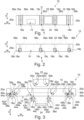
- FIG. 1 shows a dashboard assembly 10 for a vehicle in a frontal view. This means that the dashboard assembly 10 is shown as seen when looking along a longitudinal direction of a vehicle if the dashboard assembly 10 is installed in the vehicle.
- a width direction W of the dashboard assembly 10 extends from left to right in the Figure.
- This width direction W corresponds to a width direction of a vehicle, if the dashboard assembly 10 is mounted therein.
- a height direction H of the dashboard assembly 10 extends in a top-down direction of Figure 1 .
- FIG 2 shows the dashboard assembly 10 along direction II which corresponds to a top view.
- the dashboard assembly 10 is shown as seen when looking vertically downwards along the height direction H.
- This height direction H corresponds to a height direction of a vehicle if the dashboard assembly 10 is installed in the vehicle.
- a depth direction D of the dashboard assembly 10 extends in a top-down direction of Figure 2 . If the dashboard assembly 10 is installed in a vehicle, the depth direction D corresponds to a longitudinal direction of the vehicle.
- Figure 1 The perspective of Figure 1 is indicated by arrow I in Figure 2 .
- the dashboard assembly 10 comprises a dashboard body 12 which extends along the width direction W.
- a reception channel 14 is provided in the dashboard body 12.
- the reception channel 14 is configured to receive a steering column (not shown) if the dashboard assembly 10 is installed in a vehicle.
- the dashboard assembly 10 comprises a total of four ventilation modules 16a, 16b, 16c, 16d.
- Each of the ventilation modules 16a, 16b, 16c, 16d comprises an air duct ending in an air outlet 18a, 18b, 18c, 18d being configured to discharge air into a passenger compartment of the vehicle in which the dashboard assembly 10 may be installed.
- the dashboard assembly 10 comprises two side cover parts 20a, 20b being arranged at an end of the dashboard body 12 respectively when regarding the width direction W.
- the dashboard assembly 10 comprises a central cover part 22 being arranged between the ends of the dashboard body 12 when regarding the width direction W.
- the screen unit 24 for example forms part of an infotainment system.
- the ventilation module 16a is sandwiched between the side cover part 20a and the dashboard body 12 (see also Figure 3 ).
- a body-sided mounting surface 26a with a body-sided connection feature 28a and a body-sided positioning feature 30a are arranged on the dashboard body 12.
- the body-sided mounting surface 26a faces into the width direction W.
- the body-sided mounting surface 26a faces to the left.
- a side cover-sided mounting surface 32a having a side cover-sided connection feature 34a and a side cover-sided positioning feature 36a.
- the side cover-sided mounting surface 32a faces into the width direction W.
- the side cover-sided mounting surface 32a of the side cover part 20a faces towards the right.
- the ventilation module 16a comprises a counter-mounting surface 38a.
- the counter-mounting surface 38a faces into the width direction W. In the representation of Figures 1 to 3 , the counter-mounting surface 38a faces to the left.
- the counter-mounting surface 38a comprises a counter-connection feature 40a and a counter-positioning feature 42a.
- the ventilation module 16a In an assembled state of the dashboard assembly 10, the ventilation module 16a, more precisely the counter-mounting surface 38a, abuts against the side cover-sided mounting surface 32a of the side cover part 20a.
- the ventilation module 16a and the side cover part 20a are mechanically connected via the side cover-sided connection feature 34a and the counter-connection feature 40a. More precisely, the side cover-sided connection feature 34a and the counter-connection feature 40a engage each other.
- connection hook is configured to engage the connection opening.
- kinematically inverting the connection opening and the connection hook is also possible. It is understood that this is just an example and any other suitable connection features and suitable counter-connection features could be used, e.g. a threaded bolt and a corresponding nut, a gluing surface with glue and a counter-gluing surface or a welding zone and a counter-welding zone.
- the positioning feature 36a is formed as a positioning opening and the counter-positioning feature 42a is formed as a positioning protrusion. It is understood that this is just an example and any other suitable connection features and suitable counter-connection features could be used.
- the side cover part 20a and the ventilation module 16a assume a well-defined position relative to one another. Moreover, the side cover part 20a and the ventilation module 16a are connected to one another in a mechanically stable manner.
- the ventilation module 16a also comprises a further counter-mounting surface 44a.
- the counter-mounting surface 44a faces into the width direction W. In the representation of Figures 1 to 3 , the counter-mounting surface 44a faces to the right.
- the counter-mounting surface 44a comprises a counter-connection feature 46a and a counter-positioning feature 48a.
- the counter-mounting surface 38a and the further counter-mounting surface 44a are arranged on opposite sides of the ventilation module 16a.
- the ventilation module 16a In an assembled state of the dashboard assembly 10, the ventilation module 16a, more precisely the second counter-mounting surface 44a, abuts against the body-sided mounting surface 26a of the dashboard body 12.
- the ventilation module 16a and the dashboard body 12 are mechanically connected via the body-sided connection feature 28a and the counter-connection feature 46a. More precisely, the body-sided connection feature 28a and the counter-connection feature 46a engage each other.
- the body-sided connection feature 28a is formed as a connection opening and the counter-connection feature 46a is formed as a connection hook.
- the connection hook is configured to engage the connection opening.
- kinematically inverting the connection opening and the connection hook is also possible. It is understood that this is just an example and any other suitable connection features and suitable counter-connection features could be used, e.g. a threaded bolt and a corresponding nut, a gluing surface with glue and a counter-gluing surface or a welding zone and a counter-welding zone.
- the counter-positioning feature 48a and the body-sided positioning feature 30a of the dashboard body 12 engage each other.
- the positioning feature 30a is formed as a positioning opening and the counter-positioning feature 48a is formed as a positioning protrusion. It is understood that this is just an example and any other suitable connection features and suitable counter-connection features could be used.
- the dashboard body 12 and the ventilation module 16a assume a well-defined position relative to one another. Moreover, the dashboard body 12 and the ventilation module 16a are connected to one another in a mechanically stable manner.
- the ventilation module 16b is sandwiched between the side cover part 20b and the dashboard body 12.
- a body-sided mounting surface 26b with a body-sided connection feature 28b and a body-sided positioning feature 30b are arranged on the dashboard body 12.
- the body-sided mounting surface 26b faces into the width direction W.
- the body-sided mounting surface 26b faces to the right.
- a side cover-sided mounting surface 32b having a side cover-sided connection feature 34b and a side cover-sided positioning feature 36b.
- the side cover-sided mounting surface 32b faces into the width direction W.
- the side cover-sided mounting surface 32b of the side cover part 20b faces towards the left.
- the ventilation module 16b comprises a counter-mounting surface 38b.
- the counter-mounting surface 38b faces into the width direction W. In the representation of Figures 1 to 3 , the counter-mounting surface 38b faces to the right.
- the counter-mounting surface 38b comprises a counter-connection feature 40b and a counter-positioning feature 42b.
- the ventilation module 16b In an assembled state of the dashboard assembly 10, the ventilation module 16b, more precisely the first counter-mounting surface 38b, abuts against the side cover-sided mounting surface 32b of the side cover part 20b.
- the ventilation modules 16b and the side cover part 20b are mechanically connected via the side cover-sided connection feature 34b and the counter-connection feature 40b. More precisely, the side cover-sided connection feature 34b and the counter-connection feature 40b engage each other.
- connection hook is configured to engage the connection opening.
- kinematically inverting the connection opening and the connection hook is also possible. It is understood that this is just an example and any other suitable connection features and suitable counter-connection features could be used, e.g. a threaded bolt and a corresponding nut, a gluing surface with glue and a counter-gluing surface or a welding zone and a counter-welding zone.
- the positioning feature 36b is formed as a positioning opening and the counter-positioning feature 42b is formed as a positioning protrusion. It is understood that this is just an example and any other suitable connection features and suitable counter-connection features could be used.
- the side cover part 20b and the ventilation module 16b assume a well-defined position relative to one another. Moreover, the side cover part 20b and the ventilation module 16b are connected to one another in a mechanically stable manner.
- the ventilation module 16b also comprises a further counter-mounting surface 44b.
- the counter-mounting surface 44b faces into the width direction W. In the representation of Figures 1 to 3 , the counter-mounting surface 44b faces to the left.
- the counter-mounting surface 44b comprises a counter-connection feature 46b and a counter-positioning feature 48b.
- the counter-mounting surface 38b and the further counter-mounting surface 44b are arranged on opposite sides of the ventilation module 16b.
- the ventilation module 16b In an assembled state of the dashboard assembly 10, the ventilation module 16b, more precisely the second counter-mounting surface 44b, abuts against the body-sided mounting surface 26b of the dashboard body 12.
- the ventilation module 16b and the dashboard body 12 are mechanically connected via the body-sided connection feature 28b and the counter-connection feature 46b. More precisely, the body-sided connection feature 28b and the counter-connection feature 46b engage each other.
- the body-sided connection feature 28b is formed as a connection opening and the counter-connection feature 46b is formed as a connection hook.
- the connection hook is configured to engage the connection opening.
- kinematically inverting the connection opening and the connection hook is also possible. It is understood that this is just an example and any other suitable connection features and suitable counter-connection features could be used, e.g. a threaded bolt and a corresponding nut, a gluing surface with glue and a counter-gluing surface or a welding zone and a counter-welding zone.
- the counter-positioning feature 48b and the body-sided positioning feature 30b of the dashboard body 12 engage each other.
- the positioning feature 30b is formed as a positioning opening and the counter-positioning feature 48b is formed as a positioning protrusion. It is understood that this is just an example and any other suitable connection features and suitable counter-connection features could be used.
- the dashboard body 12 and the ventilation module 16b assume a well-defined position relative to one another. Moreover, the dashboard body 12 and the ventilation module 16b are connected to one another in a mechanically stable manner.
- the ventilation module 16c is sandwiched between the dashboard body 12 and the central cover part 22.
- a body-sided mounting surface 26c with a body-sided connection feature 28c and a body-sided positioning feature 30c are arranged on the dashboard body 12.
- the body-sided mounting surface 26c faces into the width direction W. In the examples of Figures 1 to 3 , the body-sided mounting surface 26c faces to the right.
- a central cover-sided mounting surface 50a having a central cover-sided connection feature 52a and a central cover-sided positioning feature 54a.
- the central cover-sided mounting surface 50a faces into the width direction W.
- the central cover-sided mounting surface 50a of the central cover part 22 faces towards the left.
- the ventilation module 16c comprises a counter-mounting surface 38c.
- the counter-mounting surface 38c faces into the width direction W. In the representation of figures 1 to 3 , the counter-mounting surface 38c faces to the left.
- the counter-mounting surface 38c comprises a counter-connection feature 40c and a counter-positioning feature 42c.
- the ventilation module 16c In an assembled state of the dashboard assembly 10, the ventilation module 16c, more precisely the counter-mounting surface 38c, abuts against the body-sided mounting surface 26c of the dashboard body 12.
- the ventilation module 16c and the dashboard body 12 are mechanically connected via the body-sided connection feature 28c and the counter-connection feature 40c. More precisely, the body-sided connection feature 28c and the counter-connection feature 40c engage each other.
- the body-sided connection feature 28c is formed as a connection opening and the counter-connection feature 40c is formed as an elastic connection hook.
- the connection hook is configured to engage the connection opening.
- kinematically inverting the connection opening and the connection hook is also possible. It is understood that this is just an example and any other suitable connection features and suitable counter-connection features could be used, e.g. a threaded bolt and a corresponding nut, a gluing surface with glue and a counter-gluing surface or a welding zone and a counter-welding zone.
- the counter-positioning feature 42c and the body-sided positioning feature 30c of the dashboard body 12 engage each other.
- the positioning feature 30c is formed as a positioning opening and the counter-positioning feature 42c is formed as a positioning protrusion. It is understood that this is just an example and any other suitable connection features and suitable counter-connection features could be used.
- the dashboard body 12 and the ventilation module 16c assume a well-defined position relative to one another. Moreover, the dashboard body 12 and the ventilation module 16c are connected to one another in a mechanically stable manner.
- the ventilation module 16c also comprises a further counter-mounting surface 44c.
- the counter-mounting surface 44c faces into the width direction W. In the representation of Figures 1 to 3 , the counter-mounting surface 44c faces to the right.
- the counter-mounting surface 44c comprises a counter-connection feature 46c and a counter-positioning feature 48c.
- the counter-mounting surface 38c and the further counter-mounting surface 44c are arranged on opposite sides of the ventilation module 16c.
- the ventilation module 16c In an assembled state of the dashboard assembly 10, the ventilation module 16c, more precisely the second counter-mounting surface 44c, abuts against the central cover-sided mounting surface 50a of the central cover part 22.
- the ventilation modules 16c and the central cover part 22 are mechanically connected via the central cover-sided connection feature 52a and the counter-connection feature 46c. More precisely, the central cover-sided connection feature 52a and the counter-connection feature 46c engage each other.
- the central cover-sided connection feature 52a is formed as a connection opening and the counter-connection feature 46c is formed as an elastic connection hook.
- the connection hook is configured to engage the connection opening.
- kinematically inverting the connection opening and the connection hook is also possible. It is understood that this is just an example and any other suitable connection features and suitable counter-connection features could be used, e.g. a threaded bolt and a corresponding nut, a gluing surface with glue and a counter-gluing surface or a welding zone and a counter-welding zone.
- the positioning feature 54a is formed as a positioning opening and the counter-positioning feature 48c is formed as a positioning protrusion. It is understood that this is just an example and any other suitable connection features and suitable counter-connection features could be used.
- the central cover part 22 and the ventilation module 16c assume a well-defined position relative to one another. Moreover, the central cover part 22 and the ventilation module 16c are connected to one another in a mechanically stable manner.
- the ventilation module 16d is sandwiched between the dashboard body 12 and the central cover part 22.
- a body-sided mounting surface 26d with a body-sided connection feature 28d and a body-sided positioning feature 30d are arranged on the dashboard body 12.
- the body-sided mounting surface 26d faces into the width direction W. In the examples of Figures 1 to 3 , the body-sided mounting surface 26d faces to the left.
- a central cover-sided mounting surface 50b having a central cover-sided connection feature 52b and a central cover-sided positioning feature 54b.
- the central cover-sided mounting surface 50b faces into the width direction W.
- the central cover-sided mounting surface 50b of the central cover part 22 faces towards the right.
- the ventilation module 16d comprises a counter-mounting surface 38d.
- the counter-mounting surface 38d faces into the width direction W. In the representation of Figures 1 to 3 , the counter-mounting surface 38d faces to the right.
- the counter-mounting surface 38d comprises a counter-connection feature 40d and a counter-positioning feature 42d.
- the ventilation module 16d In an assembled state of the dashboard assembly 10, the ventilation module 16d, more precisely the counter-mounting surface 38d, abuts against the body-sided mounting surface 26d of the dashboard body 12.
- the ventilation modules 16d and the dashboard body 12 are mechanically connected via the body-sided connection feature 28d and the counter-connection feature 40d. More precisely, the body-sided connection feature 28d and the counter-connection feature 40d engage each other.
- the body-sided connection feature 28d is formed as a connection opening and the counter-connection feature 40d is formed as an elastic connection hook.
- the connection hook is configured to engage the connection opening.
- kinematically inverting the connection opening and the connection hook is also possible. It is understood that this is just an example and any other suitable connection features and suitable counter-connection features could be used, e.g. a threaded bolt and a corresponding nut, a gluing surface with glue and a counter-gluing surface or a welding zone and a counter-welding zone.
- the counter-positioning feature 42d and the body-sided positioning feature 30d of the dashboard body 12 engage each other.
- the positioning feature 30d is formed as a positioning opening and the counter-positioning feature 42d is formed as a positioning protrusion. It is understood that this is just an example and any other suitable connection features and suitable counter-connection features could be used.
- the dashboard body 12 and the ventilation module 16d assume a well-defined position relative to one another. Moreover, the dashboard body 12 and the ventilation module 16d are connected to one another in a mechanically stable manner.
- the ventilation module 16d also comprises a further counter-mounting surface 44d.
- the counter-mounting surface 44d faces into the width direction W. In the representation of Figures 1 to 3 , the counter-mounting surface 44d faces to the left.
- the counter-mounting surface 44d comprises a counter-connection feature 46d and a counter-positioning feature 48d.
- the counter-mounting surface 38d and the further counter-mounting surface 44d are arranged on opposite sides of the ventilation module 16d.
- the ventilation module 16d In an assembled state of the dashboard assembly 10, the ventilation module 16d, more precisely the second counter-mounting surface 44d, abuts against the central cover-sided mounting surface 50b of the central cover part 22.
- the ventilation modules 16d and the central cover part 22 are mechanically connected via the central cover-sided connection feature 52b and the counter-connection feature 46d. More precisely, the central cover-sided connection feature 52b and the counter-connection feature 46d engage each other.
- the central cover-sided connection feature 52b is formed as a connection opening and the counter-connection feature 46d is formed as an elastic connection hook.
- the connection hook is configured to engage the connection opening.
- kinematically inverting the connection opening and the connection hook is also possible. It is understood that this is just an example and any other suitable connection features and suitable counter-connection features could be used, e.g. a threaded bolt and a corresponding nut, a gluing surface with glue and a counter-gluing surface or a welding zone and a counter-welding zone.
- the positioning feature 54b is formed as a positioning opening and the counter-positioning feature 48d is formed as a positioning protrusion. It is understood that this is just an example and any other suitable connection features and suitable counter-connection features could be used.
- the central cover part 22 and the ventilation module 16d assume a well-defined position relative to one another. Moreover, the central cover part 22 and the ventilation module 16d are connected to one another in a mechanically stable manner.
- side cover part 20a comprises a bezel portion 56a and side cover part 20b comprises a bezel portion 56b.
- the bezel portions 56a, 56b are located adjacent to the ventilation modules 16a, 16b (cf. Figures 1 and 2 ).
- the dashboard body 12 comprises bezel portions 58a, 58b. Also these bezel portions 58a, 58b are located adjacent to the ventilation modules 16a, 16b respectively, if the dashboard assembly 10 is mounted.
- ventilation module 16a especially air outlet 18a is framed by the bezel portions 56a, 58a.
- ventilation module 16b especially air outlet 18b is framed by the bezel portions 56b, 58b.
- the dashboard body 12 comprises bezel portions 58c, 58d these bezel portions 58c, 58d are located adjacent to the ventilation modules 16c, 16d respectively if the dashboard assembly 10 is mounted.
- the central cover part 22 comprises bezel portions 60a, 60b.
- the bezel portion 60a, 60b are located adjacent to the ventilation modules 16c, 16d respectively.
- ventilation module 16c especially air outlet 18c is framed by the bezel portions 58c, 60a.
- ventilation module 16d especially air outlet 18d, is framed by the bezel portions 58d, 60b.
- the dashboard assembly 10 as shown in Figures 1 to 3 may be assembled using a method for assembling a dashboard assembly for a vehicle.
- the ventilation module 16a is mounted as follows.
- the ventilation module 16a is abutted against the side cover-sided mounting surface 32a of the side cover part 20a. In doing so, the ventilation modules 16a and the side cover part 20a are moved relative to one another along the width direction W. Moreover, the ventilation module 16a is positioned and connected to the side cover-sided mounting surface 32a of the side cover part 20a has as has been explained above.
- the sub-assembly comprising the side cover part 20a and the ventilation module 16a are mounted on the dashboard body 12.
- the ventilation module 16a is abutted against the body-sided mounting surface of the dashboard body 12. In doing so, the sub-assembly and the dashboard body 12 are moved relative to one another along the width direction W. Additionally, the ventilation module 16a is positioned and connected to the body-sided mounting surface 26a of the dashboard body 12 as has been explained above.
- the ventilation module 16b is mounted in a similar manner.
- the ventilation module 16b is abutted against the side cover-sided mounting surface 32b of the side cover part 20b. In doing so, the ventilation module 16b and the side cover part 20b are moved relative to one another along the width direction W. Moreover, the ventilation module 16b is positioned and connected to the side cover-sided mounting surface 32b of the side cover part 20b has as has been explained above.
- the sub-assembly comprising the side cover part 20b and the ventilation module 16b are mounted on the dashboard body 12.
- the ventilation module 16b is abutted against the body-sided mounting surface 26b of the dashboard body 12. In doing so, the sub-assembly and the dashboard body 12 are moved relative to one another along the width direction W. Additionally, the ventilation module 16b is positioned and connected to the body-sided mounting surface 26b of the dashboard body 12 as has been explained above.
- the ventilation modules 16a, 16b is first abutted and connected to the dashboard body 12 and then, the side cover part 20a and/or the side cover part 20b are abutted and connected to the respective ventilation module 16a, 16b.
- the main direction of assembly is oriented along with direction W.
- ventilation modules 16c, 16d are mounted as follows.
- ventilation module 16c is abutted against the body-sided mounting surface 26c of the dashboard body 12. In doing so, the ventilation module 16c and the dashboard body 12 are moved relative to one another along the width direction W. Moreover, the ventilation module 16c is positioned and connected to the dashboard body 12 as has been explained above.
- ventilation module 16d is abutted against the body-sided mounting surface 26d of the dashboard body 12. In doing so, the ventilation module 16d and the dashboard body 12 are moved relative to one another along the width direction W. Moreover, the ventilation module 16d is positioned and connected to the dashboard body 12 as has been explained above.
- the central cover part 22 is arranged between the ventilation module 16c and the ventilation module 16d. To this end, the central cover part 22 is moved into the space between the ventilation module 16c and the ventilation module 16d along the height direction H. At the same time, the ventilation module 16c and the ventilation module 16d are positioned relatively to the central cover part 22 and connected to the central cover part 22 as has been explained above.
- the screen unit 24 is mounted on the central cover part 22. To this end, the screen unit 24 is moved towards the central cover part 22 essentially along the depth direction D. Thus, the screen unit 24 is used to seal a central portion of the central cover part 22.
Landscapes
- Engineering & Computer Science (AREA)
- Mechanical Engineering (AREA)
- Chemical & Material Sciences (AREA)
- Combustion & Propulsion (AREA)
- Transportation (AREA)
- Physics & Mathematics (AREA)
- Thermal Sciences (AREA)
- Instrument Panels (AREA)
- Air-Conditioning For Vehicles (AREA)
Abstract
Description
- The present disclosure relates to a dashboard assembly for a vehicle. The dashboard assembly comprises a dashboard body extending at least along a width direction, wherein in a state in which the dashboard body is mounted in the vehicle, the width direction extends in parallel to a width direction of the vehicle.
- Furthermore, the present disclosure relates to a ventilation module for such a dashboard assembly, to a dashboard body for such a dashboard assembly, to a side cover part for such a dashboard assembly, and to a central cover part for such a dashboard assembly.
- Additionally, the present disclosure is directed to a method for assembling a dashboard assembly for a vehicle.
- Dashboard assemblies comprising a dashboard body, one or more ventilation modules and one or more cover parts are known.
- It is an objective of the present disclosure to simplify known dashboard assemblies. In this context, known dashboard assemblies shall be simplified from a structural perspective and from the perspective of assembly. This means that a dashboard assembly shall be provided which is structurally simple and which can be assembled in a simple manner.
- The problem is at least partially solved or alleviated by the subject matter of the independent claims of the present disclosure, wherein further examples are incorporated in the dependent claims.
- According to a first aspect, there is provided a dashboard assembly for a vehicle. The dashboard assembly comprises a dashboard body extending at least along a width direction. In a state in which the dashboard body is mounted in the vehicle, the width direction extends in parallel to a width direction of the vehicle. The dashboard assembly also comprises at least one ventilation module. The ventilation module comprises an air duct ending in an air outlet being configured to discharge air into a passenger compartment of the vehicle. At least one body-sided mounting surface with a body-sided connection feature is arranged on the dashboard body. The body-sided mounting surface faces into the width direction. The at least one ventilation module abuts against the body-sided mounting surface and is connected to the dashboard body using the body-sided connection feature. In this context, the width direction is the direction of the biggest extension of the dashboard body and the dashboard assembly. It is understood that the dashboard body also extends along a height direction and along a depth direction. In a state in which the dashboard body is mounted in the vehicle, a height direction of the dashboard body corresponds to a height direction of the vehicle. Moreover, in the state in which the dashboard body is mounted in the vehicle, the depth direction of the dashboard body extends along a longitudinal direction of the vehicle. The fact that the body-sided mounting surface faces into the width direction means that the biggest component of a normal on the mounting surface extends into the width direction. It is noted that the body-sided mounting surface may comprise a plurality of surface segments. In this case, a normal on a midplane of the plurality of surface segments is used in order to assess whether the body-sided mounting surface faces into the width direction. Thus, in a state in which the dashboard assembly is mounted in the vehicle, the at least one ventilation module abuts against the body-sided mounting surface face along the width direction. An alternative term for a ventilation module is ventilation cassette. Abutting the at least one ventilation module against the body-sided mounting surface and connecting the at least one ventilation module to the body-sided connection feature is structurally simple. Comparatively few parts are necessary. Moreover, abutting the at least one ventilation module against the body-sided mounting surface along a width direction renders the assembly of the dashboard assembly simple.
- In the present disclosure, the term body-sided refers to a feature or element of the dashboard body.
- In an example, the body-sided mounting surface comprises a body-sided positioning feature. The ventilation module engages the body-sided positioning feature. The positioning feature has the effect that the ventilation module may be abutted against the body-sided mounting surface in one single well-defined position only. The well-defined position comprises a translatory position and a rotatory position of the ventilation module with respect to the dashboard body. This facilitates the assembly of the dashboard assembly. Moreover, since the positioning feature is provided on the body-sided mounting surface, very few parts are necessary.
- According to an example, the dashboard body comprises a bezel portion being located adjacent to the ventilation module. In this context, a bezel portion is to be understood as a portion of the dashboard body at least partially delimiting the ventilation module, especially the air outlet. Consequently, in a dashboard assembly according to the present disclosure, the air outlet has an optical appearance which is similar to known air outlets. Thus, for a user of the dashboard assembly or a vehicle in which the dashboard assembly is installed, the optical appearance is familiar and pleasant. However, especially in contrast to known dashboard assemblies, the bezel portion is formed as an integral portion of the dashboard body. This means that the bezel portion is not formed as a separate part. This renders the dashboard assembly structurally simple and facilitates its assembly.
- In an example, the dashboard assembly further comprises a side cover part being arranged at an end of the dashboard body when regarding the width direction. At least one side cover-sided mounting surface with a side cover-sided connection feature is arranged on the side cover part. The side cover-sided mounting surface faces into the width direction. The at least one ventilation module abuts against the side cover-sided mounting surface and is connected to the side cover part using the side cover-sided connection feature. As before, the fact that the side cover-sided mounting surface faces into the width direction means that the biggest component of a normal on the mounting surface extends into the width direction. It is noted that the side cover-sided mounting surface may comprise a plurality of surface segments. In this case, a normal on a midplane of the plurality of surface segments is used in order to assess whether the side cover-sided mounting surface faces into the width direction. Consequently, the ventilation module is sandwiched between a portion of the dashboard body and a portion of the side cover part. It is emphasized that the side cover part and the dashboard body are separate parts. Optionally, a portion of the side cover part is connected to the dashboard body in a direct manner, i.e. not via the ventilation module. Thus, when assembling the dashboard assembly, not only the ventilation module can be abutted against the dashboard body along the width direction, but also the side cover part can be abutted against the ventilation module along a width direction. It is noted that of course, different assembly orders are possible. For example, the side cover part may first be connected to the ventilation module and then the sub-assembly of the ventilation module and the side cover part may be connected to the dashboard body. In all variants, assembling the dashboard assembly is simple.
- In the present disclosure, the term side cover-sided refers to a feature or element of the side cover part.
- In an example, the side cover-sided mounting surface comprises a side cover-sided positioning feature. The ventilation module engages the side cover-sided positioning feature. The side cover-sided positioning feature has the effect that the ventilation module may be abutted against the side cover-sided mounting surface in one single well-defined position only. The well-defined position comprises a translatory position and a rotatory position of the ventilation module with respect to the side cover part. This facilitates the assembly of the dashboard assembly. Moreover, since the positioning feature is provided on the side cover-sided mounting surface, very few parts are necessary.
- In an example, the side cover part comprises a bezel portion being located adjacent to the ventilation module. As before, a bezel portion is to be understood as a portion of the side cover part at least partially delimiting the ventilation module, especially the air outlet. Consequently, in a dashboard assembly according to the present disclosure, the air outlet has an optical appearance which is similar to known air outlets. Thus, for a user of the dashboard assembly or a vehicle in which the dashboard assembly is installed, the optical appearance is familiar and pleasant. However, especially in contrast to known dashboard assemblies, the bezel portion is formed as an integral portion of the side cover part. This means that the bezel portion is not formed as a separate part. This renders the dashboard assembly structurally simple and facilitates its assembly.
- In an example, the dashboard assembly further comprises a central cover part being arranged between the ends of the dashboard body when regarding the width direction. At least one central cover-sided mounting surface with a central cover-sided connection feature is arranged on the central cover part. The central cover-sided mounting surface faces into the width direction. The at least one ventilation module abuts against the central cover-sided mounting surface and is connected to the central cover part using the central cover-sided connection feature. As explained previously, the fact that the central cover-sided mounting surface faces into the width direction means that the biggest component of a normal on the mounting surface extends into the width direction. It is noted that the central cover-sided mounting surface may comprise a plurality of surface segments. In this case, a normal on a midplane of the plurality of surface segments is used in order to assess whether the central cover-sided mounting surface faces into the width direction. Consequently, the ventilation module is sandwiched between a portion of the dashboard body and a portion of the central cover part. It is understood that the central cover part may be arranged at any position of the dashboard body between the ends of the dashboard body along the width direction. It is not necessary that the central cover part is arranged in a geometric middle of the dashboard body. It is emphasized that the central cover part and the dashboard body are separate parts. Optionally, a portion of the central cover part is connected to the dashboard body in a direct manner, i.e. not via the ventilation module. Thus, when assembling the dashboard assembly, not only the ventilation module can be abutted against the dashboard body along the width direction, but also the central cover part can be abutted against the ventilation module along a width direction. It is noted that of course, different assembly orders are possible. For example, the central cover part may first be connected to the ventilation module and then the sub-assembly of the ventilation module and the central cover part may be connected to the dashboard body. In all variants, assembling the dashboard assembly is simple.
- In the present disclosure, the term central cover-sided refers to a feature or element of the central cover part.
- In an example, the central cover-sided mounting surface comprises a central cover-sided positioning feature. The ventilation module engages the central cover-sided positioning feature. The central cover-sided positioning feature has the effect that the ventilation module may be abutted against the central cover-sided mounting surface in one single well-defined position only. The well-defined position comprises a translatory position and a rotatory position of the ventilation module with respect to the central cover part. This facilitates the assembly of the dashboard assembly. Moreover, since the positioning feature is provided on the central cover-sided mounting surface, very few parts are necessary.
- In an example, the central cover part comprises a bezel portion being located adjacent to the ventilation module. As before, a bezel portion is to be understood as a portion of the central cover part at least partially delimiting the ventilation module, especially the air outlet. Consequently, in a dashboard assembly according to the present disclosure, the air outlet has an optical appearance which is similar to known air outlets. Thus, for a user of the dashboard assembly or a vehicle in which the dashboard assembly is installed, the optical appearance is familiar and pleasant. However, especially in contrast to known dashboard assemblies, the bezel portion is formed as an integral portion of the central cover part. This means that the bezel portion is not formed as a separate part. This renders the dashboard assembly structurally simple and facilitates its assembly.
- According to a second aspect, there is provided a ventilation module for a dashboard assembly of the present disclosure. The ventilation module comprises an air duct ending in an air outlet being configured to discharge air into a passenger compartment of the vehicle. Moreover, the ventilation module comprises at least one counter-mounting surface with a counter-connection feature. The counter-mounting surface is configured to abut against a mounting surface of a dashboard body, of a side cover part or of a central cover part and the counter-connection feature is configured to engage a connection feature of the mounting surface of the dashboard body, of the side cover part or of the central cover part. Such a ventilation module is structurally simple. This renders the structure of a dashboard assembly in which the ventilation module is used also simple. Moreover, as has already been explained before, using such a ventilation module facilitates the assembly of a dashboard assembly in which it is used.
- According to an example, the at least one ventilation module comprises one or more lamellae which are configured for guiding an airstream being oriented towards the air outlet. The lamellae may also be called guiding blades. The lamellae or blades may be used in order to direct an airstream into different directions. For example, one partial airstream may be directed towards a window of the vehicle and another partial airstream may be directed towards a passenger position. The partial airstream being directed towards the window may be used for defrosting the window. Alternatively or additionally, the lamellae or blades may be adjustable. Thus, when installed in a vehicle, a user of the vehicle may adjust an airstream leaving the air outlet according to his or her preferences.
- According to a further example, the ventilation module may comprise two or more air outlets. Each of these air outlets may be configured to direct an airstream into a different direction. For example, one partial airstream may be directed towards a window of the vehicle and another partial airstream may be directed towards a passenger position. The partial airstream being directed towards the window may be used for defrosting the window.
- In an example, the ventilation module comprises two counter-mounting surfaces, each having a counter-connection feature, the counter-mounting surfaces being arranged on opposite sides of the ventilation module. Consequently, the ventilation module may be sandwiched between a dashboard body and a side cover part or between the dashboard body and a central cover part. In both alternatives, the ventilation module may be reliably connected to the respective other parts. Consequently, the ventilation module may be mounted within the dashboard assembly in a mechanically stable manner.
- According to a third aspect, there is provided a dashboard body for a dashboard assembly of the present disclosure. The dashboard body extends at least along a width direction, wherein in a state in which the dashboard body is mounted in a vehicle, the width direction extends in parallel to a width direction of the vehicle. At least one body-sided mounting surface with a body-sided connection feature is arranged on the dashboard body. The body-sided mounting surface faces into the width direction. Such a dashboard body is structurally simple. This renders the structure of a dashboard assembly in which the dashboard body is used also simple. Moreover, as has already been explained before, using such a dashboard body facilitates the assembly of a dashboard assembly in which it is used.
- According to a fourth aspect, there is provided a side cover part for a dashboard assembly of the present disclosure. The side cover part has at least one side cover-sided mounting surface with a side cover-sided connection feature. The side cover-sided mounting surface faces into a width direction when the side cover part is mounted in the dashboard assembly. Such a side cover part is structurally simple. This renders the structure of a dashboard assembly in which the side cover part is used also simple. Moreover, as has already been explained before, using such a side cover part facilitates the assembly of a dashboard assembly in which it is used.
- According to a fifth aspect, there is provided a central cover part for a dashboard assembly of the present disclosure. The central cover part has at least one central cover-sided mounting surface with a central cover-sided connection feature. The central cover-sided mounting surface faces into a width direction when the central cover part is mounted in the dashboard assembly. Such a central cover part is structurally simple. This renders the structure of a dashboard assembly in which the central cover part is used also simple. Moreover, as has already been explained before, using such a central cover part facilitates the assembly of a dashboard assembly in which it is used.
- In an example, the central cover part comprises a mounting interface for a central infotainment unit. The central infotainment unit may comprise a screen unit. Thus, the central cover part fulfills two functionalities. The first functionality relates to holding the at least one ventilation module and the second functionality relates to mounting the central infotainment unit to the remaining parts of the dashboard assembly. Due to this double functionality, comparatively few parts are necessary.
- According to a sixth aspect, there is provided a method for assembling a dashboard assembly for a vehicle. The method comprises:
- abutting a ventilation module against a body-sided mounting surface of a dashboard body or a side cover-sided mounting surface of a side cover part by moving the ventilation module and the dashboard body or side cover part relative to one another along a width direction, and
- connecting the ventilation module to the body-sided mounting surface of the dashboard body or to the side cover-sided mounting surface of the side cover part using a connection feature.
- Thus, a mounting direction corresponds to the width direction of the dashboard body. In other words, the ventilation module is stacked on the dashboard body or on the side cover part along the width direction. This is a very simple manner of assembling a dashboard assembly.
- According to an example, the method according to the present disclosure is executed in connection with the dashboard assembly of the present disclosure.
- In an example, the method further comprises:
- abutting an additional ventilation module against a body-sided mounting surface of a dashboard body or a central cover-sided mounting surface of a central cover part by moving the additional ventilation module and the dashboard body or central cover part relative to one another along a width direction, and
- connecting the additional ventilation module to the body-sided mounting surface of the dashboard body or to the central cover-sided mounting surface of the central cover part using a connection feature.
- It should be noted that the above examples may be combined with each other irrespective of the aspect involved.
- These and other aspects of the present disclosure will become apparent from and elucidated with reference to the examples described hereinafter.
- Examples of the disclosure will be described in the following with reference to the following drawings.
- Figure 1
- shows a dashboard assembly according to the present disclosure in a frontal view, wherein the dashboard assembly comprises a dashboard body according to the present disclosure, a central cover part according to the present disclosure, four ventilation modules according to the present disclosure and two side cover parts according to the present disclosure and wherein the dashboard assembly may be assembled using the method according to the present disclosure,
- Figure 2
- shows the dashboard assembly of
Figure 1 in a top view along direction II inFigure 1 , and - Figure 3
- shows the dashboard assembly of
Figures 1 and 2 in an exploded view which corresponds to the top view ofFigure 2 . - The Figures are merely schematic representations and serve only to illustrate examples of the disclosure. Identical or equivalent elements are in principle provided with the same reference signs.
-
Figure 1 shows adashboard assembly 10 for a vehicle in a frontal view. This means that thedashboard assembly 10 is shown as seen when looking along a longitudinal direction of a vehicle if thedashboard assembly 10 is installed in the vehicle. - Consequently, a width direction W of the
dashboard assembly 10 extends from left to right in the Figure. This width direction W corresponds to a width direction of a vehicle, if thedashboard assembly 10 is mounted therein. - A height direction H of the
dashboard assembly 10 extends in a top-down direction ofFigure 1 . -
Figure 2 shows thedashboard assembly 10 along direction II which corresponds to a top view. In other words, inFigure 2 thedashboard assembly 10 is shown as seen when looking vertically downwards along the height direction H. This height direction H corresponds to a height direction of a vehicle if thedashboard assembly 10 is installed in the vehicle. - A depth direction D of the
dashboard assembly 10 extends in a top-down direction ofFigure 2 . If thedashboard assembly 10 is installed in a vehicle, the depth direction D corresponds to a longitudinal direction of the vehicle. - The perspective of
Figure 1 is indicated by arrow I inFigure 2 . - The
dashboard assembly 10 comprises adashboard body 12 which extends along the width direction W. - A
reception channel 14 is provided in thedashboard body 12. Thereception channel 14 is configured to receive a steering column (not shown) if thedashboard assembly 10 is installed in a vehicle. - Moreover, the
dashboard assembly 10 comprises a total of fourventilation modules - Each of the
ventilation modules air outlet dashboard assembly 10 may be installed. - Furthermore, the
dashboard assembly 10 comprises twoside cover parts dashboard body 12 respectively when regarding the width direction W. - Additionally, the
dashboard assembly 10 comprises acentral cover part 22 being arranged between the ends of thedashboard body 12 when regarding the width direction W. - On the
central cover part 22, there is arranged ascreen unit 24. Thescreen unit 24 for example forms part of an infotainment system. - The
ventilation module 16a is sandwiched between theside cover part 20a and the dashboard body 12 (see alsoFigure 3 ). - To this end, a body-
sided mounting surface 26a with a body-sided connection feature 28a and a body-sided positioning feature 30a are arranged on thedashboard body 12. The body-sided mounting surface 26a faces into the width direction W. In the examples ofFigures 1 to 3 , the body-sided mounting surface 26a faces to the left. - Moreover, on the
side cover part 20a, there is provided a side cover-sided mounting surface 32a having a side cover-sided connection feature 34a and a side cover-sided positioning feature 36a. The side cover-sided mounting surface 32a faces into the width direction W. In the Figures, the side cover-sided mounting surface 32a of theside cover part 20a faces towards the right. - The
ventilation module 16a comprises acounter-mounting surface 38a. Thecounter-mounting surface 38a faces into the width direction W. In the representation ofFigures 1 to 3 , thecounter-mounting surface 38a faces to the left. - The
counter-mounting surface 38a comprises acounter-connection feature 40a and acounter-positioning feature 42a. - In an assembled state of the
dashboard assembly 10, theventilation module 16a, more precisely thecounter-mounting surface 38a, abuts against the side cover-sided mounting surface 32a of theside cover part 20a. - Moreover, the
ventilation module 16a and theside cover part 20a are mechanically connected via the side cover-sided connection feature 34a and thecounter-connection feature 40a. More precisely, the side cover-sided connection feature 34a and thecounter-connection feature 40a engage each other. - In the example shown in the Figures, the side cover-
sided connection feature 34a is formed as a connection opening and thecounter-connection feature 40a is formed as a connection hook. The connection hook is configured to engage the connection opening. Of course, kinematically inverting the connection opening and the connection hook is also possible. It is understood that this is just an example and any other suitable connection features and suitable counter-connection features could be used, e.g. a threaded bolt and a corresponding nut, a gluing surface with glue and a counter-gluing surface or a welding zone and a counter-welding zone. - Furthermore, the
counter-positioning feature 42a and the side cover-sided positioning feature 36a of theside cover part 20a engage each other. - In the example shown in the Figures, the
positioning feature 36a is formed as a positioning opening and thecounter-positioning feature 42a is formed as a positioning protrusion. It is understood that this is just an example and any other suitable connection features and suitable counter-connection features could be used. - Consequently, the
side cover part 20a and theventilation module 16a assume a well-defined position relative to one another. Moreover, theside cover part 20a and theventilation module 16a are connected to one another in a mechanically stable manner. - The
ventilation module 16a also comprises a furthercounter-mounting surface 44a. Thecounter-mounting surface 44a faces into the width direction W. In the representation ofFigures 1 to 3 , thecounter-mounting surface 44a faces to the right. - The
counter-mounting surface 44a comprises acounter-connection feature 46a and acounter-positioning feature 48a. - The
counter-mounting surface 38a and the furthercounter-mounting surface 44a are arranged on opposite sides of theventilation module 16a. - In an assembled state of the
dashboard assembly 10, theventilation module 16a, more precisely the secondcounter-mounting surface 44a, abuts against the body-sided mounting surface 26a of thedashboard body 12. - Moreover, the
ventilation module 16a and thedashboard body 12 are mechanically connected via the body-sided connection feature 28a and thecounter-connection feature 46a. More precisely, the body-sided connection feature 28a and thecounter-connection feature 46a engage each other. - In the example shown in the Figures, the body-
sided connection feature 28a is formed as a connection opening and thecounter-connection feature 46a is formed as a connection hook. The connection hook is configured to engage the connection opening. Of course, kinematically inverting the connection opening and the connection hook is also possible. It is understood that this is just an example and any other suitable connection features and suitable counter-connection features could be used, e.g. a threaded bolt and a corresponding nut, a gluing surface with glue and a counter-gluing surface or a welding zone and a counter-welding zone. - Furthermore, the
counter-positioning feature 48a and the body-sided positioning feature 30a of thedashboard body 12 engage each other. - In the example shown in the Figures, the
positioning feature 30a is formed as a positioning opening and thecounter-positioning feature 48a is formed as a positioning protrusion. It is understood that this is just an example and any other suitable connection features and suitable counter-connection features could be used. - Consequently, the
dashboard body 12 and theventilation module 16a assume a well-defined position relative to one another. Moreover, thedashboard body 12 and theventilation module 16a are connected to one another in a mechanically stable manner. - The
ventilation module 16b is sandwiched between theside cover part 20b and thedashboard body 12. - To this end, a body-sided mounting surface 26b with a body-sided connection feature 28b and a body-
sided positioning feature 30b are arranged on thedashboard body 12. The body-sided mounting surface 26b faces into the width direction W. In the examples ofFigures 1 to 3 , the body-sided mounting surface 26b faces to the right. - Moreover, on the
side cover part 20b, there is provided a side cover-sided mounting surface 32b having a side cover-sided connection feature 34b and a side cover-sided positioning feature 36b. The side cover-sided mounting surface 32b faces into the width direction W. In the Figures, the side cover-sided mounting surface 32b of theside cover part 20b faces towards the left. - The
ventilation module 16b comprises acounter-mounting surface 38b. Thecounter-mounting surface 38b faces into the width direction W. In the representation ofFigures 1 to 3 , thecounter-mounting surface 38b faces to the right. - The
counter-mounting surface 38b comprises acounter-connection feature 40b and acounter-positioning feature 42b. - In an assembled state of the
dashboard assembly 10, theventilation module 16b, more precisely the firstcounter-mounting surface 38b, abuts against the side cover-sided mounting surface 32b of theside cover part 20b. - Moreover, the
ventilation modules 16b and theside cover part 20b are mechanically connected via the side cover-sided connection feature 34b and thecounter-connection feature 40b. More precisely, the side cover-sided connection feature 34b and thecounter-connection feature 40b engage each other. - In the example shown in the Figures, the side cover-
sided connection feature 34b is formed as a connection opening and thecounter-connection feature 40b is formed as a connection hook. The connection hook is configured to engage the connection opening. Of course, kinematically inverting the connection opening and the connection hook is also possible. It is understood that this is just an example and any other suitable connection features and suitable counter-connection features could be used, e.g. a threaded bolt and a corresponding nut, a gluing surface with glue and a counter-gluing surface or a welding zone and a counter-welding zone. - Furthermore, the
counter-positioning feature 42b and the side cover-sided positioning feature 36b of theside cover part 20b engage each other. - In the example shown in the Figures, the
positioning feature 36b is formed as a positioning opening and thecounter-positioning feature 42b is formed as a positioning protrusion. It is understood that this is just an example and any other suitable connection features and suitable counter-connection features could be used. - Consequently, the
side cover part 20b and theventilation module 16b assume a well-defined position relative to one another. Moreover, theside cover part 20b and theventilation module 16b are connected to one another in a mechanically stable manner. - The
ventilation module 16b also comprises a furthercounter-mounting surface 44b. Thecounter-mounting surface 44b faces into the width direction W. In the representation ofFigures 1 to 3 , thecounter-mounting surface 44b faces to the left. - The
counter-mounting surface 44b comprises acounter-connection feature 46b and acounter-positioning feature 48b. - The
counter-mounting surface 38b and the furthercounter-mounting surface 44b are arranged on opposite sides of theventilation module 16b. - In an assembled state of the
dashboard assembly 10, theventilation module 16b, more precisely the secondcounter-mounting surface 44b, abuts against the body-sided mounting surface 26b of thedashboard body 12. - Moreover, the
ventilation module 16b and thedashboard body 12 are mechanically connected via the body-sided connection feature 28b and thecounter-connection feature 46b. More precisely, the body-sided connection feature 28b and thecounter-connection feature 46b engage each other. - In the example shown in the Figures, the body-sided connection feature 28b is formed as a connection opening and the
counter-connection feature 46b is formed as a connection hook. The connection hook is configured to engage the connection opening. Of course, kinematically inverting the connection opening and the connection hook is also possible. It is understood that this is just an example and any other suitable connection features and suitable counter-connection features could be used, e.g. a threaded bolt and a corresponding nut, a gluing surface with glue and a counter-gluing surface or a welding zone and a counter-welding zone. - Furthermore, the
counter-positioning feature 48b and the body-sided positioning feature 30b of thedashboard body 12 engage each other. - In the example shown in the Figures, the
positioning feature 30b is formed as a positioning opening and thecounter-positioning feature 48b is formed as a positioning protrusion. It is understood that this is just an example and any other suitable connection features and suitable counter-connection features could be used. - Consequently, the
dashboard body 12 and theventilation module 16b assume a well-defined position relative to one another. Moreover, thedashboard body 12 and theventilation module 16b are connected to one another in a mechanically stable manner. - The
ventilation module 16c is sandwiched between thedashboard body 12 and thecentral cover part 22. - To this end, a body-
sided mounting surface 26c with a body-sided connection feature 28c and a body-sided positioning feature 30c are arranged on thedashboard body 12. The body-sided mounting surface 26c faces into the width direction W. In the examples ofFigures 1 to 3 , the body-sided mounting surface 26c faces to the right. - Moreover, on the
central cover part 22, there is provided a central cover-sided mounting surface 50a having a central cover-sided connection feature 52a and a central cover-sided positioning feature 54a. The central cover-sided mounting surface 50a faces into the width direction W. In the Figures, the central cover-sided mounting surface 50a of thecentral cover part 22 faces towards the left. - The
ventilation module 16c comprises acounter-mounting surface 38c. Thecounter-mounting surface 38c faces into the width direction W. In the representation offigures 1 to 3 , thecounter-mounting surface 38c faces to the left. - The
counter-mounting surface 38c comprises acounter-connection feature 40c and acounter-positioning feature 42c. - In an assembled state of the
dashboard assembly 10, theventilation module 16c, more precisely thecounter-mounting surface 38c, abuts against the body-sided mounting surface 26c of thedashboard body 12. - Moreover, the
ventilation module 16c and thedashboard body 12 are mechanically connected via the body-sided connection feature 28c and thecounter-connection feature 40c. More precisely, the body-sided connection feature 28c and thecounter-connection feature 40c engage each other. - In the example shown in the Figures, the body-sided connection feature 28c is formed as a connection opening and the
counter-connection feature 40c is formed as an elastic connection hook. The connection hook is configured to engage the connection opening. Of course, kinematically inverting the connection opening and the connection hook is also possible. It is understood that this is just an example and any other suitable connection features and suitable counter-connection features could be used, e.g. a threaded bolt and a corresponding nut, a gluing surface with glue and a counter-gluing surface or a welding zone and a counter-welding zone. - Furthermore, the
counter-positioning feature 42c and the body-sided positioning feature 30c of thedashboard body 12 engage each other. - In the example shown in the Figures, the positioning feature 30c is formed as a positioning opening and the
counter-positioning feature 42c is formed as a positioning protrusion. It is understood that this is just an example and any other suitable connection features and suitable counter-connection features could be used. - Consequently, the
dashboard body 12 and theventilation module 16c assume a well-defined position relative to one another. Moreover, thedashboard body 12 and theventilation module 16c are connected to one another in a mechanically stable manner. - The
ventilation module 16c also comprises a furthercounter-mounting surface 44c. Thecounter-mounting surface 44c faces into the width direction W. In the representation ofFigures 1 to 3 , thecounter-mounting surface 44c faces to the right. - The
counter-mounting surface 44c comprises acounter-connection feature 46c and acounter-positioning feature 48c. - The
counter-mounting surface 38c and the furthercounter-mounting surface 44c are arranged on opposite sides of theventilation module 16c. - In an assembled state of the
dashboard assembly 10, theventilation module 16c, more precisely the secondcounter-mounting surface 44c, abuts against the central cover-sided mounting surface 50a of thecentral cover part 22. - Moreover, the
ventilation modules 16c and thecentral cover part 22 are mechanically connected via the central cover-sided connection feature 52a and thecounter-connection feature 46c. More precisely, the central cover-sided connection feature 52a and thecounter-connection feature 46c engage each other. - In the example shown in the Figures, the central cover-sided connection feature 52a is formed as a connection opening and the
counter-connection feature 46c is formed as an elastic connection hook. The connection hook is configured to engage the connection opening. Of course, kinematically inverting the connection opening and the connection hook is also possible. It is understood that this is just an example and any other suitable connection features and suitable counter-connection features could be used, e.g. a threaded bolt and a corresponding nut, a gluing surface with glue and a counter-gluing surface or a welding zone and a counter-welding zone. - Furthermore, the
counter-positioning feature 48c and the central cover-sided positioning feature 54a of thecover part 22 engage each other. - In the example shown in the Figures, the
positioning feature 54a is formed as a positioning opening and thecounter-positioning feature 48c is formed as a positioning protrusion. It is understood that this is just an example and any other suitable connection features and suitable counter-connection features could be used. - Consequently, the
central cover part 22 and theventilation module 16c assume a well-defined position relative to one another. Moreover, thecentral cover part 22 and theventilation module 16c are connected to one another in a mechanically stable manner. - The
ventilation module 16d is sandwiched between thedashboard body 12 and thecentral cover part 22. - To this end, a body-
sided mounting surface 26d with a body-sided connection feature 28d and a body-sided positioning feature 30d are arranged on thedashboard body 12. The body-sided mounting surface 26d faces into the width direction W. In the examples ofFigures 1 to 3 , the body-sided mounting surface 26d faces to the left. - Moreover, on the
central cover part 22, there is provided a central cover-sided mounting surface 50b having a central cover-sided connection feature 52b and a central cover-sided positioning feature 54b. The central cover-sided mounting surface 50b faces into the width direction W. In the figures, the central cover-sided mounting surface 50b of thecentral cover part 22 faces towards the right. - The
ventilation module 16d comprises acounter-mounting surface 38d. Thecounter-mounting surface 38d faces into the width direction W. In the representation ofFigures 1 to 3 , thecounter-mounting surface 38d faces to the right. - The
counter-mounting surface 38d comprises acounter-connection feature 40d and acounter-positioning feature 42d. - In an assembled state of the
dashboard assembly 10, theventilation module 16d, more precisely thecounter-mounting surface 38d, abuts against the body-sided mounting surface 26d of thedashboard body 12. - Moreover, the
ventilation modules 16d and thedashboard body 12 are mechanically connected via the body-sided connection feature 28d and thecounter-connection feature 40d. More precisely, the body-sided connection feature 28d and thecounter-connection feature 40d engage each other. - In the example shown in the Figures, the body-
sided connection feature 28d is formed as a connection opening and thecounter-connection feature 40d is formed as an elastic connection hook. The connection hook is configured to engage the connection opening. Of course, kinematically inverting the connection opening and the connection hook is also possible. It is understood that this is just an example and any other suitable connection features and suitable counter-connection features could be used, e.g. a threaded bolt and a corresponding nut, a gluing surface with glue and a counter-gluing surface or a welding zone and a counter-welding zone. - Furthermore, the
counter-positioning feature 42d and the body-sided positioning feature 30d of thedashboard body 12 engage each other. - In the example shown in the Figures, the
positioning feature 30d is formed as a positioning opening and thecounter-positioning feature 42d is formed as a positioning protrusion. It is understood that this is just an example and any other suitable connection features and suitable counter-connection features could be used. - Consequently, the
dashboard body 12 and theventilation module 16d assume a well-defined position relative to one another. Moreover, thedashboard body 12 and theventilation module 16d are connected to one another in a mechanically stable manner. - The
ventilation module 16d also comprises a furthercounter-mounting surface 44d. Thecounter-mounting surface 44d faces into the width direction W. In the representation ofFigures 1 to 3 , thecounter-mounting surface 44d faces to the left. - The
counter-mounting surface 44d comprises acounter-connection feature 46d and acounter-positioning feature 48d. - The
counter-mounting surface 38d and the furthercounter-mounting surface 44d are arranged on opposite sides of theventilation module 16d. - In an assembled state of the
dashboard assembly 10, theventilation module 16d, more precisely the secondcounter-mounting surface 44d, abuts against the central cover-sided mounting surface 50b of thecentral cover part 22. - Moreover, the
ventilation modules 16d and thecentral cover part 22 are mechanically connected via the central cover-sided connection feature 52b and thecounter-connection feature 46d. More precisely, the central cover-sided connection feature 52b and thecounter-connection feature 46d engage each other. - In the example shown in the Figures, the central cover-sided connection feature 52b is formed as a connection opening and the
counter-connection feature 46d is formed as an elastic connection hook. The connection hook is configured to engage the connection opening. Of course, kinematically inverting the connection opening and the connection hook is also possible. It is understood that this is just an example and any other suitable connection features and suitable counter-connection features could be used, e.g. a threaded bolt and a corresponding nut, a gluing surface with glue and a counter-gluing surface or a welding zone and a counter-welding zone. - Furthermore, the
counter-positioning feature 48d and the central cover-sided positioning feature 54b of thecover part 22 engage each other. - In the example shown in the Figures, the
positioning feature 54b is formed as a positioning opening and thecounter-positioning feature 48d is formed as a positioning protrusion. It is understood that this is just an example and any other suitable connection features and suitable counter-connection features could be used. - Consequently, the
central cover part 22 and theventilation module 16d assume a well-defined position relative to one another. Moreover, thecentral cover part 22 and theventilation module 16d are connected to one another in a mechanically stable manner. - Beyond that, side cover
part 20a comprises abezel portion 56a and side coverpart 20b comprises abezel portion 56b. In a mounted state of the dashboard assembly, thebezel portions ventilation modules Figures 1 and 2 ). - Moreover, the
dashboard body 12 comprisesbezel portions bezel portions ventilation modules dashboard assembly 10 is mounted. - Consequently,
ventilation module 16a, especiallyair outlet 18a is framed by thebezel portions ventilation module 16b, especiallyair outlet 18b is framed by thebezel portions - Additionally, the
dashboard body 12 comprisesbezel portions bezel portions ventilation modules dashboard assembly 10 is mounted. - Furthermore, the
central cover part 22 comprisesbezel portions dashboard assembly 10, thebezel portion ventilation modules - Consequently,
ventilation module 16c, especiallyair outlet 18c is framed by thebezel portions ventilation module 16d, especiallyair outlet 18d, is framed by thebezel portions - The
dashboard assembly 10 as shown inFigures 1 to 3 may be assembled using a method for assembling a dashboard assembly for a vehicle. - In this context, the
ventilation module 16a is mounted as follows. - In a first step, the
ventilation module 16a is abutted against the side cover-sided mounting surface 32a of theside cover part 20a. In doing so, theventilation modules 16a and theside cover part 20a are moved relative to one another along the width direction W. Moreover, theventilation module 16a is positioned and connected to the side cover-sided mounting surface 32a of theside cover part 20a has as has been explained above. - Subsequently, the sub-assembly comprising the
side cover part 20a and theventilation module 16a are mounted on thedashboard body 12. To this end, theventilation module 16a is abutted against the body-sided mounting surface of thedashboard body 12. In doing so, the sub-assembly and thedashboard body 12 are moved relative to one another along the width direction W. Additionally, theventilation module 16a is positioned and connected to the body-sided mounting surface 26a of thedashboard body 12 as has been explained above. - The
ventilation module 16b is mounted in a similar manner. - In a first step, the
ventilation module 16b is abutted against the side cover-sided mounting surface 32b of theside cover part 20b. In doing so, theventilation module 16b and theside cover part 20b are moved relative to one another along the width direction W. Moreover, theventilation module 16b is positioned and connected to the side cover-sided mounting surface 32b of theside cover part 20b has as has been explained above. - Subsequently, the sub-assembly comprising the
side cover part 20b and theventilation module 16b are mounted on thedashboard body 12. To this end, theventilation module 16b is abutted against the body-sided mounting surface 26b of thedashboard body 12. In doing so, the sub-assembly and thedashboard body 12 are moved relative to one another along the width direction W. Additionally, theventilation module 16b is positioned and connected to the body-sided mounting surface 26b of thedashboard body 12 as has been explained above. - It is noted that it is of course also possible that at least one of the
ventilation modules dashboard body 12 and then, theside cover part 20a and/or theside cover part 20b are abutted and connected to therespective ventilation module - Moreover, when executing the method,
ventilation modules - In a first step,
ventilation module 16c is abutted against the body-sided mounting surface 26c of thedashboard body 12. In doing so, theventilation module 16c and thedashboard body 12 are moved relative to one another along the width direction W. Moreover, theventilation module 16c is positioned and connected to thedashboard body 12 as has been explained above. - Additionally,
ventilation module 16d is abutted against the body-sided mounting surface 26d of thedashboard body 12. In doing so, theventilation module 16d and thedashboard body 12 are moved relative to one another along the width direction W. Moreover, theventilation module 16d is positioned and connected to thedashboard body 12 as has been explained above. - Thereafter, the
central cover part 22 is arranged between theventilation module 16c and theventilation module 16d. To this end, thecentral cover part 22 is moved into the space between theventilation module 16c and theventilation module 16d along the height direction H. At the same time, theventilation module 16c and theventilation module 16d are positioned relatively to thecentral cover part 22 and connected to thecentral cover part 22 as has been explained above. - In a last step, the
screen unit 24 is mounted on thecentral cover part 22. To this end, thescreen unit 24 is moved towards thecentral cover part 22 essentially along the depth direction D. Thus, thescreen unit 24 is used to seal a central portion of thecentral cover part 22. - Other variations to the disclosed examples can be understood and effected by those skilled in the art in practicing the claimed disclosure, from the study of the drawings, the disclosure, and the appended claims. In the claims the word "comprising" does not exclude other elements or steps and the indefinite article "a" or "an" does not exclude a plurality. The mere fact that certain measures are recited in mutually different dependent claims does not indicate that a combination of these measures cannot be used to advantage. Any reference signs in the claims should not be construed as limiting the scope of the claims.
-
- 10
- dashboard assembly
- 12
- dashboard body
- 14
- reception channel
- 16a
- ventilation module
- 16b
- ventilation module
- 16c
- ventilation module
- 16d
- ventilation module
- 18a
- air outlet
- 18b
- air outlet
- 18c
- air outlet
- 18d
- air outlet
- 20a
- side cover part
- 20b
- side cover part
- 22
- central cover part
- 24
- screen unit
- 26a
- body-sided mounting surface
- 26b
- body-sided mounting surface
- 26c
- body-sided mounting surface
- 26d
- body-sided mounting surface
- 28a
- body-sided connection feature
- 28b
- body-sided connection feature
- 28c
- body-sided connection feature
- 28d
- body-sided connection feature
- 30a
- body-sided positioning feature
- 30b
- body-sided positioning feature
- 30c
- body-sided positioning feature
- 30d
- body-sided positioning feature
- 32a
- side cover-sided mounting surface
- 32b
- side cover-sided mounting surface
- 34a
- side cover-sided connection feature
- 34b
- side cover-sided connection feature
- 36a
- side cover-sided positioning feature
- 36b
- side cover-sided positioning feature
- 38a
- counter-mounting surface
- 38b
- counter-mounting surface
- 38c
- counter-mounting surface
- 38d
- counter-mounting surface
- 40a
- counter-connection feature
- 40b
- counter-connection feature
- 40c
- counter-connection feature
- 40d
- counter-connection feature
- 42a
- counter-positioning feature
- 42b
- counter-positioning feature
- 42c
- counter-positioning feature
- 42d
- counter-positioning feature
- 44a
- counter-mounting surface
- 44b
- counter-mounting surface
- 44c
- counter-mounting surface
- 44d
- counter-mounting surface
- 46a
- counter-connection feature
- 46b
- counter-connection feature
- 46c
- counter-connection feature
- 46d
- counter-connection feature
- 48a
- counter-positioning feature
- 48b
- counter-positioning feature
- 48c
- counter-positioning feature
- 48d
- counter-positioning feature
- 50a
- central cover-sided mounting surface
- 50b
- central cover-sided mounting surface
- 52a
- central cover-sided connection feature
- 52b
- central cover-sided connection feature
- 54a
- central cover-sided positioning feature
- 54b
- central cover-sided positioning feature
- 56a
- bezel portion
- 56b
- bezel portion
- 58a
- bezel portion
- 58b
- bezel portion
- 58c
- bezel portion
- 58d
- bezel portion
- 60a
- bezel portion
- 60b
- bezel portion
- W
- width direction
- H
- height direction
- D
- depth direction
Claims (15)
- A dashboard assembly (10) for a vehicle, comprisinga dashboard body (12) extending at least along a width direction (W), wherein in a state in which the dashboard body (12) is mounted in the vehicle, the width direction (W) extends in parallel to a width direction of the vehicle, andat least one ventilation module (16a, 16b, 16c, 16d), comprising an air duct ending in an air outlet (18a, 18b, 18c, 18d) being configured to discharge air into a passenger compartment of the vehicle,wherein at least one body-sided mounting surface (26a, 26b, 26c, 26d) with a body-sided connection feature (28a, 28b, 28c, 28d) is arranged on the dashboard body (12), the body-sided mounting surface (26a, 26b, 26c, 26d) facing into the width direction (W), andwherein the at least one ventilation module (16a, 16b, 16c, 16d) abuts against the body-sided mounting surface (26a, 26b, 26c, 26d) and is connected to the dashboard body (12) using the body-sided connection feature (28a, 28b, 28c, 28d).
- The dashboard assembly (10) of claim 1, wherein the body-sided mounting surface (26a, 26b, 26c, 26d) comprises a body-sided positioning feature (30a, 30b, 30c, 30d) and wherein the ventilation module (16a, 16b, 16c, 16d) engages the body-sided positioning feature (30a, 30b, 30c, 30d).
- The dashboard assembly (10) of any one of the preceding claims, wherein the dashboard body (12) comprises a bezel portion (58a, 58b, 58c, 58d) being located adjacent to the ventilation module (16a, 16b, 16c, 16d).
- The dashboard assembly (10) of any one of the preceding claims, further comprising a side cover part (20a, 20b) being arranged at an end of the dashboard body (12) when regarding the width direction (W),
wherein at least one side cover-sided mounting surface (32a, 32b) with a side cover-sided connection feature (34a, 34b) is arranged on the side cover part (20a, 20b), the side cover-sided mounting surface (32a, 32b) facing into the width direction (W), and wherein the at least one ventilation module (16a, 16b) abuts against the side cover-sided mounting surface (32a, 32b) and is connected to the side cover part (20a, 20b) using the side cover-sided connection feature (34a, 34b). - The dashboard assembly (10) of claim 4, wherein the side cover-sided mounting surface (32a, 32b) comprises a side cover-sided positioning feature (36a, 36b) and wherein the ventilation module (16a, 16b) engages the side cover-sided positioning feature (36a, 36b).
- The dashboard assembly (10) of claim 4 or 5, wherein the side cover part (20a, 20b) comprises a bezel portion (56a, 56b) being located adjacent to the ventilation module (16a, 16b).
- The dashboard assembly (10) of any one of the preceding claims, further comprising a central cover part (22) being arranged between the ends of the dashboard body (12) when regarding the width direction (W), wherein at least one central cover-sided mounting surface (50a, 50b) with a central cover-sided connection feature (52a, 52b) is arranged on the central cover part (22), the central cover-sided mounting surface (50a, 50b) facing into the width direction (W), and wherein the at least one ventilation module (16c, 16d) abuts against the central cover-sided mounting surface (50a, 50b) and is connected to the central cover part (22) using the central cover-sided connection feature (52a, 52b).
- The dashboard assembly (10) of claim 7, wherein the central cover-sided mounting surface (50a, 50b) comprises a central cover-sided positioning feature (54a, 54b) and wherein the ventilation module (16c, 16d) engages the central cover-sided positioning feature (54a, 54b).
- The dashboard assembly (10) of claim 7 or 8, wherein the central cover part (22) comprises a bezel portion (60a, 60b) being located adjacent to the ventilation module (16c, 16d).
- A ventilation module (16a, 16b, 16c, 16d) for a dashboard assembly (10) of any one of the preceding claims, comprising an air duct ending in an air outlet (18a, 18b, 18c, 18d) being configured to discharge air into a passenger compartment of the vehicle, and at least one counter-mounting surface (38a, 38b, 38c, 38d, 44a, 44b, 44c, 44d) with a counter-connection feature (40a, 40b, 40c, 40d, 46a, 46b, 46c, 46d), the counter-mounting surface (38a, 38b, 38c, 38d, 44a, 44b, 44c, 44d) being configured to abut against a mounting surface (26a, 26b, 26c, 26d, 32a, 32b, 50a, 50b) of a dashboard body (12), of a side cover part (20a, 20b) or of a central cover part (22) and the counter-connection feature (40a, 40b, 40c, 40d, 46a, 46b,46c, 46d) being configured to engage a connection feature (28a, 28b, 28c, 28d, 34a, 34b, 52a, 52b) of the mounting surface (26a, 26b, 26c, 26d, 32a, 32b, 50a, 50b) of the dashboard body (12), of the side cover part (20a, 20b) or of the central cover part (22).
- The ventilation module (16a, 16b, 16c, 16d) of claim 10, wherein the ventilation module (16a, 16b, 16c, 16d) comprises two counter-mounting surfaces (38a, 38b, 38c, 38d, 44a, 44b, 44c, 44d), each having a counter-connection feature (40a, 40b, 40c, 40d, 46a, 46b, 46c, 46d), the counter-mounting surfaces (38a, 38b, 38c, 38d, 44a, 44b, 44c, 44d) being arranged on opposite sides of the ventilation module (16a, 16b, 16c, 16d).
- A dashboard body (12) for a dashboard assembly (10) of any one of claims 1 to 9, extending at least along a width direction (W), wherein in a state in which the dashboard body (12) is mounted in a vehicle, the width direction (W) extends in parallel to a width direction of the vehicle,
wherein at least one body-sided mounting surface (26a, 26b, 26c, 26d) with a body-sided connection feature (28a, 28b, 28c, 28d) is arranged on the dashboard body (12), the body-sided mounting surface (26a, 26b, 26c, 26d) facing into the width direction (W). - A side cover part (20a, 20b) for a dashboard assembly (10) of any one of claims 1 to 9, having at least one side cover-sided mounting surface (32a, 32b) with a side cover-sided connection feature (34a, 34b), the side cover-sided mounting surface (32a, 32b) facing into a width direction (W) when the side cover part (20a, 20b) is mounted in the dashboard assembly (10).
- A central cover part (22) for a dashboard assembly (10) of any one of claims 1 to 9, having at least one central cover-sided mounting surface (50a, 50b) with a central cover-sided connection feature (52a, 52b), the central cover-sided mounting surface (50a, 50b) facing into a width direction (W) when the central cover part (22) is mounted in the dashboard assembly (10).
- A method for assembling a dashboard assembly (10) for a vehicle, comprising- abutting a ventilation module (16a, 16b, 16c, 16d) against a body-sided mounting surface (26a, 26b, 26c, 26d) of a dashboard body (12) or a side cover-sided mounting surface (32a, 32b) of a side cover part (20a, 20b) by moving the ventilation module (16a, 16b, 16c, 16d) and the dashboard body (12) or side cover part (20a, 20b) relative to one another along a width direction (W), and- connecting the ventilation module (16a, 16b, 16c, 16d) to the body-sided mounting surface (26a, 26b, 26c, 26d) of the dashboard body (12) or to the side cover-sided mounting surface (32a, 32b) of the side cover part (20a, 20b) using a connection feature (28a, 28b, 28c, 28d, 34a, 34b).
Priority Applications (3)
| Application Number | Priority Date | Filing Date | Title |
|---|---|---|---|
| EP23162905.6A EP4434780B1 (en) | 2023-03-20 | 2023-03-20 | Dashboard assembly for a vehicle, ventilation module, dashboard body, side cover part, central cover part, and method for assembling a dashboard assembly for a vehicle |
| CN202410283130.4A CN118665173A (en) | 2023-03-20 | 2024-03-13 | Vehicle instrument panel assembly, ventilation module, instrument panel body, side cover portion, center cover portion, and method of assembling a vehicle instrument panel assembly |
| US18/611,011 US20240317317A1 (en) | 2023-03-20 | 2024-03-20 | Dashboard assembly for a vehicle |
Applications Claiming Priority (1)
| Application Number | Priority Date | Filing Date | Title |
|---|---|---|---|
| EP23162905.6A EP4434780B1 (en) | 2023-03-20 | 2023-03-20 | Dashboard assembly for a vehicle, ventilation module, dashboard body, side cover part, central cover part, and method for assembling a dashboard assembly for a vehicle |
Publications (2)
| Publication Number | Publication Date |
|---|---|
| EP4434780A1 true EP4434780A1 (en) | 2024-09-25 |
| EP4434780B1 EP4434780B1 (en) | 2026-03-04 |
Family
ID=85704575
Family Applications (1)
| Application Number | Title | Priority Date | Filing Date |
|---|---|---|---|
| EP23162905.6A Active EP4434780B1 (en) | 2023-03-20 | 2023-03-20 | Dashboard assembly for a vehicle, ventilation module, dashboard body, side cover part, central cover part, and method for assembling a dashboard assembly for a vehicle |
Country Status (3)
| Country | Link |
|---|---|
| US (1) | US20240317317A1 (en) |
| EP (1) | EP4434780B1 (en) |
| CN (1) | CN118665173A (en) |
Citations (4)
| Publication number | Priority date | Publication date | Assignee | Title |
|---|---|---|---|---|
| US20160039270A1 (en) * | 2014-08-08 | 2016-02-11 | Toyota Jidosha Kabushiki Kaisha | Register fixing structure for a vehicle |
| US20190047377A1 (en) * | 2017-08-08 | 2019-02-14 | Moriroku Technology Company, Ltd. | Air conditioning blower hole apparatus |
| CN112060907A (en) * | 2020-08-31 | 2020-12-11 | 丹阳市新联汽车配件有限公司 | Multifunctional instrument desk for automobile |
| KR102436283B1 (en) * | 2022-02-16 | 2022-08-26 | 주식회사 성지솔루션 | Air vent for car |
Family Cites Families (8)
| Publication number | Priority date | Publication date | Assignee | Title |
|---|---|---|---|---|
| DE10215347A1 (en) * | 2001-04-10 | 2002-12-12 | Denso Corp | Vehicle air conditioning duct structure, method of manufacturing the same, and electrical wiring structure |
| JP4239594B2 (en) * | 2002-04-10 | 2009-03-18 | 株式会社デンソー | Air conditioning duct structure for vehicles |
| US6688680B1 (en) * | 2002-12-17 | 2004-02-10 | Bayer Polymers Llc | Molded cross vehicle beam |
| US7044538B2 (en) * | 2004-05-10 | 2006-05-16 | Lear Corporation | Center stack face plate with integrated HVAC duct assembly |
| FR2895355B1 (en) * | 2005-12-22 | 2008-04-04 | Valeo Systemes Thermiques | CLOSING PLATE AND REINFORCING BEAM FOR AUTOMOBILE COMPARTMENT INTEGRATING SUCH PLATE |
| FR2901529B1 (en) * | 2006-05-24 | 2008-10-31 | Faurecia Interieur Ind Snc | AUTOMOTIVE VEHICLE BOARD TRAVERSE |
| US8641134B2 (en) * | 2012-04-02 | 2014-02-04 | Ford Global Technologies, Llc | Air ducts formed in automotive structural members |
| GB2535764A (en) * | 2015-02-26 | 2016-08-31 | Aston Martin Lagonda Ltd | Structural cross-member |
-
2023
- 2023-03-20 EP EP23162905.6A patent/EP4434780B1/en active Active
-
2024
- 2024-03-13 CN CN202410283130.4A patent/CN118665173A/en active Pending
- 2024-03-20 US US18/611,011 patent/US20240317317A1/en active Pending
Patent Citations (4)
| Publication number | Priority date | Publication date | Assignee | Title |
|---|---|---|---|---|
| US20160039270A1 (en) * | 2014-08-08 | 2016-02-11 | Toyota Jidosha Kabushiki Kaisha | Register fixing structure for a vehicle |
| US20190047377A1 (en) * | 2017-08-08 | 2019-02-14 | Moriroku Technology Company, Ltd. | Air conditioning blower hole apparatus |
| CN112060907A (en) * | 2020-08-31 | 2020-12-11 | 丹阳市新联汽车配件有限公司 | Multifunctional instrument desk for automobile |
| KR102436283B1 (en) * | 2022-02-16 | 2022-08-26 | 주식회사 성지솔루션 | Air vent for car |
Also Published As
| Publication number | Publication date |
|---|---|
| EP4434780B1 (en) | 2026-03-04 |
| US20240317317A1 (en) | 2024-09-26 |
| CN118665173A (en) | 2024-09-20 |
Similar Documents
| Publication | Publication Date | Title |
|---|---|---|
| EP1483135B1 (en) | Headlamp mounting structure of automobile | |
| JP7046230B2 (en) | In-module media assembly | |
| US8104819B2 (en) | Audio bracket fore and aft slip plane | |
| CN102239070A (en) | Mounting structure of airbag device for driver's seat and steering wheel | |
| EP2548787B1 (en) | Vehicle front part structure | |
| US11530010B2 (en) | Windshield device for vehicle | |
| EP3330131B1 (en) | Bracket device, system comprising a bracket device and a sensor unit, and a vehicle | |
| EP4434780A1 (en) | Dashboard assembly for a vehicle, ventilation module, dashboard body, side cover part, central cover part, and method for assembling a dashboard assembly for a vehicle | |
| US20200047817A1 (en) | Vehicle front structure | |
| JP4233506B2 (en) | Automotive instrument panel mounting device | |
| JP4445545B2 (en) | Headlamp mounting structure | |
| CN201580266U (en) | Automobile instrument panel blocking connection structure | |
| JP2010000897A (en) | Instrument panel section structure for vehicle | |
| KR20220067036A (en) | Mounting bracket for room lamp of vehicle | |
| KR20220017166A (en) | Chassis frame for electric vehicle | |
| KR20210067169A (en) | Cowl cross for a car | |
| US11919566B2 (en) | Stop for absorbing lateral loads | |
| CN110475695A (en) | Airbag device for interior trim elements of motor vehicles | |
| US20250214503A1 (en) | Fastening device for fastening a headlamp in a motor vehicle, a headlamp assembly, a motor vehicle, a kit comprising a plurality of fastening devices | |
| CN113365876A (en) | Vehicle comprising a glazing support assembled by riveting | |
| CN109774412A (en) | Air conditioner filter element disassembly and assembly structure | |
| EP3168072B1 (en) | Frame of a sunroof arrangement and/or of a vehicle shading system | |
| KR20210013893A (en) | Coupling structure of head-up display | |
| KR100986362B1 (en) | Vehicle airbag device | |
| KR200240839Y1 (en) | Lamp adhesion structure of inner of vehicles |
Legal Events
| Date | Code | Title | Description |
|---|---|---|---|
| PUAI | Public reference made under article 153(3) epc to a published international application that has entered the european phase |
Free format text: ORIGINAL CODE: 0009012 |
|
| STAA | Information on the status of an ep patent application or granted ep patent |
Free format text: STATUS: REQUEST FOR EXAMINATION WAS MADE |
|
| 17P | Request for examination filed |
Effective date: 20231211 |
|
| AK | Designated contracting states |
Kind code of ref document: A1 Designated state(s): AL AT BE BG CH CY CZ DE DK EE ES FI FR GB GR HR HU IE IS IT LI LT LU LV MC ME MK MT NL NO PL PT RO RS SE SI SK SM TR |
|
| RIC1 | Information provided on ipc code assigned before grant |
Ipc: B60H 1/00 20060101AFI20250829BHEP Ipc: B60K 35/00 20240101ALI20250829BHEP Ipc: B60H 1/34 20060101ALI20250829BHEP Ipc: B60K 37/00 20240101ALI20250829BHEP |
|
| GRAP | Despatch of communication of intention to grant a patent |
Free format text: ORIGINAL CODE: EPIDOSNIGR1 |
|
| STAA | Information on the status of an ep patent application or granted ep patent |
Free format text: STATUS: GRANT OF PATENT IS INTENDED |
|
| INTG | Intention to grant announced |
Effective date: 20251016 |
|
| GRAS | Grant fee paid |
Free format text: ORIGINAL CODE: EPIDOSNIGR3 |
|
| GRAA | (expected) grant |
Free format text: ORIGINAL CODE: 0009210 |
|
| STAA | Information on the status of an ep patent application or granted ep patent |
Free format text: STATUS: THE PATENT HAS BEEN GRANTED |
|
| AK | Designated contracting states |
Kind code of ref document: B1 Designated state(s): AL AT BE BG CH CY CZ DE DK EE ES FI FR GB GR HR HU IE IS IT LI LT LU LV MC ME MK MT NL NO PL PT RO RS SE SI SK SM TR |
|
| REG | Reference to a national code |
Ref country code: CH Ref legal event code: F10 Free format text: ST27 STATUS EVENT CODE: U-0-0-F10-F00 (AS PROVIDED BY THE NATIONAL OFFICE) Effective date: 20260304 Ref country code: GB Ref legal event code: FG4D |
|
| REG | Reference to a national code |
Ref country code: DE Ref legal event code: R096 Ref document number: 602023012821 Country of ref document: DE |
|
| REG | Reference to a national code |
Ref country code: IE Ref legal event code: FG4D |
|
| PGFP | Annual fee paid to national office [announced via postgrant information from national office to epo] |
Ref country code: DE Payment date: 20260219 Year of fee payment: 4 |
|
| PGFP | Annual fee paid to national office [announced via postgrant information from national office to epo] |
Ref country code: AT Payment date: 20260303 Year of fee payment: 4 |
|
| P01 | Opt-out of the competence of the unified patent court (upc) registered |
Free format text: CASE NUMBER: UPC_APP_0009604_4434780/2026 Effective date: 20260311 |