EP4434774A1 - Pneumatic tire - Google Patents
Pneumatic tire Download PDFInfo
- Publication number
- EP4434774A1 EP4434774A1 EP24159362.3A EP24159362A EP4434774A1 EP 4434774 A1 EP4434774 A1 EP 4434774A1 EP 24159362 A EP24159362 A EP 24159362A EP 4434774 A1 EP4434774 A1 EP 4434774A1
- Authority
- EP
- European Patent Office
- Prior art keywords
- tire
- bead
- radial direction
- pneumatic tire
- outer end
- Prior art date
- Legal status (The legal status is an assumption and is not a legal conclusion. Google has not performed a legal analysis and makes no representation as to the accuracy of the status listed.)
- Granted
Links
Images


Classifications
-
- B—PERFORMING OPERATIONS; TRANSPORTING
- B60—VEHICLES IN GENERAL
- B60C—VEHICLE TYRES; TYRE INFLATION; TYRE CHANGING; CONNECTING VALVES TO INFLATABLE ELASTIC BODIES IN GENERAL; DEVICES OR ARRANGEMENTS RELATED TO TYRES
- B60C15/00—Tyre beads, e.g. ply turn-up or overlap
- B60C15/06—Flipper strips, fillers, or chafing strips and reinforcing layers for the construction of the bead
- B60C15/0628—Flipper strips, fillers, or chafing strips and reinforcing layers for the construction of the bead comprising a bead reinforcing layer
-
- B—PERFORMING OPERATIONS; TRANSPORTING
- B60—VEHICLES IN GENERAL
- B60C—VEHICLE TYRES; TYRE INFLATION; TYRE CHANGING; CONNECTING VALVES TO INFLATABLE ELASTIC BODIES IN GENERAL; DEVICES OR ARRANGEMENTS RELATED TO TYRES
- B60C15/00—Tyre beads, e.g. ply turn-up or overlap
- B60C15/06—Flipper strips, fillers, or chafing strips and reinforcing layers for the construction of the bead
- B60C15/0628—Flipper strips, fillers, or chafing strips and reinforcing layers for the construction of the bead comprising a bead reinforcing layer
- B60C15/0635—Flipper strips, fillers, or chafing strips and reinforcing layers for the construction of the bead comprising a bead reinforcing layer using chippers between the carcass layer and chafer rubber wrapped around the bead
-
- B—PERFORMING OPERATIONS; TRANSPORTING
- B60—VEHICLES IN GENERAL
- B60C—VEHICLE TYRES; TYRE INFLATION; TYRE CHANGING; CONNECTING VALVES TO INFLATABLE ELASTIC BODIES IN GENERAL; DEVICES OR ARRANGEMENTS RELATED TO TYRES
- B60C15/00—Tyre beads, e.g. ply turn-up or overlap
- B60C15/06—Flipper strips, fillers, or chafing strips and reinforcing layers for the construction of the bead
- B60C15/0603—Flipper strips, fillers, or chafing strips and reinforcing layers for the construction of the bead characterised by features of the bead filler or apex
-
- B—PERFORMING OPERATIONS; TRANSPORTING
- B60—VEHICLES IN GENERAL
- B60C—VEHICLE TYRES; TYRE INFLATION; TYRE CHANGING; CONNECTING VALVES TO INFLATABLE ELASTIC BODIES IN GENERAL; DEVICES OR ARRANGEMENTS RELATED TO TYRES
- B60C1/00—Tyres characterised by the chemical composition or the physical arrangement or mixture of the composition
- B60C2001/005—Compositions of the bead portions, e.g. clinch or chafer rubber or cushion rubber
-
- B—PERFORMING OPERATIONS; TRANSPORTING
- B60—VEHICLES IN GENERAL
- B60C—VEHICLE TYRES; TYRE INFLATION; TYRE CHANGING; CONNECTING VALVES TO INFLATABLE ELASTIC BODIES IN GENERAL; DEVICES OR ARRANGEMENTS RELATED TO TYRES
- B60C15/00—Tyre beads, e.g. ply turn-up or overlap
- B60C15/06—Flipper strips, fillers, or chafing strips and reinforcing layers for the construction of the bead
- B60C15/0603—Flipper strips, fillers, or chafing strips and reinforcing layers for the construction of the bead characterised by features of the bead filler or apex
- B60C2015/061—Dimensions of the bead filler in terms of numerical values or ratio in proportion to section height
-
- B—PERFORMING OPERATIONS; TRANSPORTING
- B60—VEHICLES IN GENERAL
- B60C—VEHICLE TYRES; TYRE INFLATION; TYRE CHANGING; CONNECTING VALVES TO INFLATABLE ELASTIC BODIES IN GENERAL; DEVICES OR ARRANGEMENTS RELATED TO TYRES
- B60C15/00—Tyre beads, e.g. ply turn-up or overlap
- B60C15/06—Flipper strips, fillers, or chafing strips and reinforcing layers for the construction of the bead
- B60C2015/0614—Flipper strips, fillers, or chafing strips and reinforcing layers for the construction of the bead characterised by features of the chafer or clinch portion, i.e. the part of the bead contacting the rim
-
- B—PERFORMING OPERATIONS; TRANSPORTING
- B60—VEHICLES IN GENERAL
- B60C—VEHICLE TYRES; TYRE INFLATION; TYRE CHANGING; CONNECTING VALVES TO INFLATABLE ELASTIC BODIES IN GENERAL; DEVICES OR ARRANGEMENTS RELATED TO TYRES
- B60C15/00—Tyre beads, e.g. ply turn-up or overlap
- B60C15/06—Flipper strips, fillers, or chafing strips and reinforcing layers for the construction of the bead
- B60C2015/0617—Flipper strips, fillers, or chafing strips and reinforcing layers for the construction of the bead comprising a cushion rubber other than the chafer or clinch rubber
-
- B—PERFORMING OPERATIONS; TRANSPORTING
- B60—VEHICLES IN GENERAL
- B60C—VEHICLE TYRES; TYRE INFLATION; TYRE CHANGING; CONNECTING VALVES TO INFLATABLE ELASTIC BODIES IN GENERAL; DEVICES OR ARRANGEMENTS RELATED TO TYRES
- B60C15/00—Tyre beads, e.g. ply turn-up or overlap
- B60C15/06—Flipper strips, fillers, or chafing strips and reinforcing layers for the construction of the bead
- B60C15/0628—Flipper strips, fillers, or chafing strips and reinforcing layers for the construction of the bead comprising a bead reinforcing layer
- B60C2015/0678—Physical properties of the bead reinforcing layer, e.g. modulus of the ply
-
- B—PERFORMING OPERATIONS; TRANSPORTING
- B60—VEHICLES IN GENERAL
- B60C—VEHICLE TYRES; TYRE INFLATION; TYRE CHANGING; CONNECTING VALVES TO INFLATABLE ELASTIC BODIES IN GENERAL; DEVICES OR ARRANGEMENTS RELATED TO TYRES
- B60C15/00—Tyre beads, e.g. ply turn-up or overlap
- B60C15/06—Flipper strips, fillers, or chafing strips and reinforcing layers for the construction of the bead
- B60C15/0628—Flipper strips, fillers, or chafing strips and reinforcing layers for the construction of the bead comprising a bead reinforcing layer
- B60C2015/0682—Physical properties or dimensions of the coating rubber
Definitions
- the present invention relates to a pneumatic tire.
- Japanese Unexamined Patent Application Publication No. 2017-074834 describes a pneumatic tire with insulations located between the carcass and inner liner.
- the insulations each have an insulation bottom portion located radially between a core and a bottom surface of a chafer.
- the present invention was made in view of the above, and a primary object thereof is to provide a pneumatic tire capable of improving the cornering performance while maintaining vibration absorbing performance.
- the present invention is a pneumatic tire including:
- the pneumatic tire of the present invention can improve the cornering performance while maintaining the vibration absorbing performance.
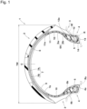
- FIG. 1 is a tire meridian section of a pneumatic tire 1 according to an embodiment of the present invention (hereinafter, may be simply referred to as "tire 1") in a standard state.
- the tire meridian section is a cross section passing all through the tire rotational axis (not shown) of the tire 1.
- FIG. 1 shows the tire 1 for motorcycles (motor cycle tire) as a preferred embodiment.
- the tire 1 has a tread width TW, which is an axial distance between tread edges (i.e., a distance between the axially outermost ground contacting positions of the ground contacting surface of a tread portion 2 described below) and the maximum width of the tire.
- TW is an axial distance between tread edges (i.e., a distance between the axially outermost ground contacting positions of the ground contacting surface of a tread portion 2 described below) and the maximum width of the tire.
- the present invention may be employed in tires for passenger cars or for heavy duty tires, for example.
- standard state refers to a state in which the tire 1 is assembled on a standard rim (R), inflated to a standard inner pressure, and loaded with no tire load.
- the “standard rim (R)” refers to a wheel rim specified for the concerned tire by a standard included in a standardization system on which the tire is based, for example, the "normal wheel rim” in JATMA, "Design Rim” in TRA, and “Measuring Rim” in ETRTO.
- standard inner pressure refers to air pressure specified for the concerned tire by a standard included in a standardization system on which the tire is based, for example, the maximum air pressure in JATMA, maximum value listed in the "TIRE LOAD LIMITS AT VARIOUS COLD INFLATION PRESSURES" table in TRA, and "INFLATION PRESSURE” in ETRTO.
- the tire 1 in the present embodiment includes a pair of bead portions 4.
- Each of the bead portions 4 includes a bead bottom surface (4a) and a bead outer side surface (4b).
- the bead bottom surface (4a) is the outer surface of each of the bead portions 4 facing inward in the tire radial direction, and contacts a rim seat (Rs) of the standard rim (R) (hereinafter, may be simply referred to as "rim (R)").
- rim (R) rim seat
- the bead bottom surface (4a) has a tapered angle that slopes inward in the tire radial direction toward the inner side in the tire axial direction.
- the bead outer side surface (4b) is the outer surface of each of the bead portions 4 facing outward in the tire axial direction and contacts a rim flange (Rf) of the rim (R).
- Each of the bead portions 4 is provided with a bead core 5. Further, the tire 1 includes a pair of sidewall portions 3 each disposed radially outside a respective one of the bead portions 4, and the tread portion 2 that connects the sidewall portions 3, for example.
- At least one of the bead portions 4 is provided with a reinforcing filler 10 made of a rubber composition and arranged along the bead core 5 of the at least one of the bead portions 4.
- the reinforcing filler 10 is disposed in each of the bead portions 4.
- the reinforcing filler 10 includes an inner portion 11, an outer portion 12, and a middle portion 13.
- the inner portion 11 has a part located axially inside the bead core 5 and extends therefrom in the tire radial direction on the axially inner side of the bead core 5.
- the outer portion 12 extends in the tire radial direction on the axially outer side of the bead core 5.
- the middle portion 13 extends in the tire axial direction on the radially inner side of the bead core 5 so as to connect the inner portion 11 and the outer portion 12, more specifically, so as to connect the radially inner end of the inner portion 11 and the radially inner end of the outer portion 12.
- the middle portion 13 configured as such increases the rubber volume on the radially inner side of the bead core 5, therefore, the rim tightening force is increased, thereby, the cornering performance is improved.
- the outer portion 12 has an outer end (12e) in the tire radial direction located radially inside an outer end (11e) in the tire radial direction of the inner portion 11.
- the outer portion 12 configured as such suppresses an excessive increase in the rigidity of the tire, therefore, the vibration during running is suppressed, thereby, the vibration absorbing performance is maintained high.
- the region where the inner portion 11 is located is a region where a large amount of deflection occurs during running since the region where the inner portion 11 is located is further away from the rim flange (Rf) than the region where the outer portion 12 is located.
- the inner portion 11 which has the outer end (11e) located radially outside the outer end (12e) of the outer portion 12, in the area where the inner portion 11 should be arranged, the deflection of the tire during running can be effectively suppressed, thereby, the cornering performance can be further improved.
- FIG. 2 is an enlarged partial view of the tire 1 of FIG. 1 .
- the outer end (12e) of the outer portion 12 is located radially outside a center position (5c) in the tire radial direction of a section height (Ha) of the bead core 5.
- the outer portion 12 configured as such positions the bead core 5 on the axially inner side, i.e., the bead core 5 is shifted more toward axially inner side, therefore, a larger rubber volume is secured in the radially inner part of the bead core 5, thereby, the cornering performance is further improved.
- the tire 1 of the present embodiment can improve the cornering performance while maintaining the vibration absorbing performance.
- the reinforcing filler 10 configured as such is formed from the following rubber composition.
- the rubber composition has a loss tangent tan ⁇ at 70 degrees Celsius of preferably 0.06 or more, more preferably 0.2 or more, and preferably 1.5 or less, more preferably 1.0 or less. Since the loss tangent tan ⁇ is 0.06 or more, a vibration absorbing effect can be maintained high. Since the loss tangent tan ⁇ is 1.5 or less, a decrease in the rigidity due to heat generation can be suppressed, therefore, the cornering performance can be improved. Further, the rubber composition has a rubber hardness at 23 degrees Celsius of preferably 65 degrees or more, more preferably 70 degrees or more, and preferably 85 degrees or less, more preferably 80 degrees or less.
- the rubber hardness is 65 degrees or more, the rigidity of the tire 1 is ensured and the cornering performance can be improved. Since the rubber hardness is 85 degrees or less, the vibration absorbing effect can be maintained high. Furthermore, the rubber composition has an elongation at break at 23 degrees Celsius of preferably 200% or more, and more preferably 350% or more. Since the elongation at break is 200% or more, the deformation of the sidewall portions 3 and the bead portions 4 can be suppressed, thereby, the cornering performance can be improved. If the elongation at break is excessively large, the vibration absorbing performance may be deteriorated. Therefore, it is preferred that the elongation at break is 550% or less and more preferably 500% or less.
- the reinforcing filler 10 in the present embodiment does not contain any cord.
- the "loss tangent tan ⁇ " is measured in accordance with Japanese Industrial Standards JIS-K6394 under the following conditions by using a dynamic viscoelasticity measurement device (EPLEXOR series) manufactured by GABO QUALIMETER Testanlagen GmbH.
- the "rubber hardness” refers to hardness measured by using a type-A durometer in accordance with Japanese Industrial Standards JIS-K6253 at a standard temperature of 23 degrees Celsius ⁇ 2 degrees Celsius.
- the "elongation at break” can be measured in accordance with Japanese Industrial Standards JIS K6251 in the section "Rubber, vulcanized or thermoplastic -- Determination of tensile stress-strain properties", for example.
- the tire 1 in the present embodiment includes a carcass 6 extending between the bead portions 4.
- the carcass 6 is formed of at least one, in the present embodiment, one carcass ply 6A, for example.
- the carcass ply 6A includes, for example, a main body portion (6a) extending between the bead cores 5 of the bead portions 4, and turned up portions (6b) each turned up around a respective one of the bead cores 5 from the inside to the outside in the tire axial direction to extend further in the tire radial direction.
- the tire 1 includes a belt layer 7 disposed radially outside the carcass 6 and in the tread portion 2.
- the belt layer 7 includes at least one belt ply, in the present embodiment two belt plies 7A and 7B.
- the belt ply 7A (radially inner belt ply), which is arranged radially inside the belt ply 7B (radially outer belt ply), is adjacent to (in contact with in the present embodiment) the carcass 6 on the outside in the tire radial direction, for example.
- the belt ply 7B is adjacent to (in contact with in the present embodiment) the inner belt ply 7A on the outside in the tire radial direction so as to be overlaid with each other in the tire radial direction in the present embodiment, and has a larger width in the tire axial direction than the inner belt ply 7A.
- the two belt plies 7A and 7B and the carcass ply 6A in the present embodiment are made of well-known constituent materials including cords and topping rubber.
- the tire 1 in the present embodiment includes an inner liner 9 and a chafer 14.
- the inner liner 9 constitutes an inner cavity surface (1b) of the tire 1, for example.
- the inner liner 9 has excellent air shielding properties.
- the inner liner 9 holds the internal pressure of the tire 1.
- the chafer 14 in the present embodiment contacts the rim seat (Rs) and the rim flange (Rf) of the rim (R).
- the chafer 14 is made of a well-known rubber material with excellent wear resistance and is harder than the inner liner 9 and the reinforcing filler 10.
- the inner liner 9 and the chafer 14 are each formed from well-known rubber materials.
- the turned up portion (6b), the outer portion 12, and the chafer 14 are disposed axially outside the bead core 5 over the section height (Ha) in the tire radial direction of the bead core 5. Further, in the present embodiment, the turned up portions (6b), the middle portion 13, the inner liner 9, and the chafer 14 are disposed radially inside the bead core 5 over a cross sectional width (Wa) in the tire axial direction of the bead core 5.
- Each of the bead portions 4 has a tire thickness (d1) (first tire thickness) between the outer surface (bead outer side surface (4b)) of the bead portion 4 and the turned up portion (6b) in the section height (Ha) (i.e., in the radial range corresponding to the section height (Ha) or in the radial range from the radially innermost end to the radially outermost end of the bead core 5).
- the tire thickness (d1) is preferably 1.5 mm or more. more preferably 2.0 mm or more, and preferably 4.0 mm or less, and more preferably 3.5 mm or less.
- the bead core 5 can be positioned more toward axially inner side, therefore, the effect of increasing the rubber volume of the radially inner part of the bead core 5 can be exerted.
- damage to the bead portions 4 due to contact between the turned up portions (6b) and the rim flange (Rf) can be suppressed, thereby, the cornering performance can be improved.
- the tire thickness (d1) is 4.0 mm or less, the rim tightening force can be maintained high.
- Each of the bead portions 4 has a tire thickness (d2) (second tire thickness) between the turned up portion (6b) and the outer surface (bead bottom surface (4a)) of the bead portion 4 in the cross sectional width (Wa) in the tire axial direction (i.e., in the axial range corresponding to the cross sectional width (Wa) or in the axial range from the axially innermost end to the axially outermost end of the bead core 5).
- the tire thickness (d2) is preferably 2.0 mm or more, more preferably 3.0 mm or more, and preferably 8.0 mm or less, more preferably 7.0 mm or less. Since the tire thickness (d2) is 2.0 mm or more, the rim tightening force can be increased. Since the tire thickness (d2) is 8.0 mm or less, excessive increase in the rim tightening force can be suppressed, therefore, rim assembly performance, which is the ease of mounting the tire on the rim (R), can be maintained.
- FIG. 3 is an enlarged partial view of the tire 1 of FIG. 1 .
- the outer portion 12 in each of the bead portions 4, the outer portion 12 is disposed axially outside the turned up portion (6b).
- the outer portion 12 in the present embodiment is disposed between the turned up portion (6b) and the chafer 14. Since the outer portion 12 is axially outside the turned up portion (6b), it is expected to suppress the transmission of vibration from the bead core 5 to the rim (R) when riding over gaps in the road surface.
- the outer end (12e) of the outer portion 12 is located radially inside an outer end (Re) in the tire radial direction of the rim flange (Rf).
- the bead portions 4 which are in contact with the rim flange (Rf) are areas where deformation (including deflection) during running is relatively small.
- a separation distance (La) (first separation distance) in the tire radial direction between the outer end (12e) of the outer portion 12 and the outer end (Re) of the rim flange (Rf) is preferably 5 mm or less, and more preferably 3 mm or less, for example.
- the outer end (Re) of the rim flange (Rf) in the present embodiment is located radially inside an outer end (6e) in the tire radial direction of the turned up portion (6b).
- the outer end (12e) of the outer portion 12 is located radially inside the outer end (6e) in the tire radial direction of the turned up portion (6b), for example.
- the outer end (6e) of the turned up portion (6b) and the outer end (12e) of the outer portion 12 are misaligned in the tire radial direction, therefore, changes in the rigidity of the sidewall portion 3 and the bead portion 4 can be decreased, thereby, the deflection during running can be reduced.
- a separation distance (Lb) (second separation distance) in the tire radial direction between the outer end (12e) of the outer portion 12 and the outer end (6e) of the turned up portion (6b) is preferably 2 times or more, more preferably 2.5 times or more the separation distance (La) and preferably 4 times or less, more preferably 3.5 times or less the separation distance (La), for example.
- the inner portion 11 is located axially inside the main body portion (6a).
- the inner portion 11 configured as such performs a compressive deformation during running and applies a tensile force to the above-mentioned cords in the main body portion (6a), which helps to increase the rigidity of the sidewall portions 3 and improve the cornering performance.
- the inner portion 11 configured as such acts like a damper against the load during running, thereby, the vibration absorbing performance is improved.
- the inner portion 11 in the present embodiment is arranged between the main body portion (6a) and the inner liner 9.
- the outer end (11e) of the inner portion 11 is located in the tread portion 2 and axially inside an outer end (7e) in the tire axial direction of the belt layer 7, for example. Therefore, the outer end (11e) is separated from the sidewall portions 3, where the deflection during running is relatively large, thereby, the cornering performance can be further improved.
- the outer end (11e) of the inner portion 11 in the present embodiment is located in the tread portion 2 and axially inside an outer end (7x) in the tire axial direction of the radially inner belt ply 7A, which has a width smaller than a width of the radially outer belt ply 7B.
- a separation distance (Lc) (third separation distance) in the tire axial direction between the outer end (11e) of the inner portion 11 and the outer end (7x) of the radially inner belt ply 7A is preferably 1% or more, more preferably 5% or more of the tread width TW, and preferably 20% or less, more preferably 15% or less of the tread width TW.
- the "A” in Table 1 is the configuration shown in FIG. 2 .
- the "B” is the configuration in which the outer end of the outer portion is located radially inside the center position of the section height of the bead core.
- the “C” is the configuration shown in FIG. 2 .
- the “D” is the configuration in which the outer end of the inner portion is located in the tread portion and axially outside the outer end of the belt layer.
- test tires were mounted on a front wheel of a motorcycle with a displacement of 250 cc under the following conditions.
- a test rider drove the above-mentioned vehicle on a test course of a dry asphalt road surface.
- the test rider sensually evaluated each of the test tires on rigid impression, responsiveness, the cornering performance in terms of steering operability, and the vibration absorbing performance in terms of stability when riding over gaps and the like during the drive.
- the results are indicated by an evaluation point based on Reference 1 being 100, wherein the larger numerical value is better.
- the present invention includes the following aspects.
- a pneumatic tire including:
- the pneumatic tire according to Present Invention 2 further including a carcass extending between the bead portions, wherein
- the pneumatic tire according to Present Invention 3 further including a tread portion, wherein
- pneumatic tire according to any one of Present Inventions 1 to 7, wherein the pneumatic tire is a motorcycle tire having a tread width being the maximum width of the pneumatic tire.
Landscapes
- Engineering & Computer Science (AREA)
- Mechanical Engineering (AREA)
- Tires In General (AREA)
Abstract
Description
- This application claims the benefit of foreign priority to Japanese Patent Application No.
JP2023-044371, filed March 20, 2023 - The present invention relates to a pneumatic tire.
-
Japanese Unexamined Patent Application Publication No. 2017-074834 - In recent years, there has been a demand for improving cornering performance, which is running stability during cornering. In order to improve the cornering performance, it is important to increase a rim tightening force, which is the fitting pressure between bead portions and a rim, for example. In particular, in motorcycle tires used for motorcycles which are tilted during cornering, it is particularly important to increase the rim tightening force. However, increasing the rim tightening force causes increased vibration and the like when riding over gaps in the road surface.
- The present invention was made in view of the above, and a primary object thereof is to provide a pneumatic tire capable of improving the cornering performance while maintaining vibration absorbing performance.
- The present invention is a pneumatic tire including:
- a pair of bead portions each provided with a bead core; and
- a reinforcing filler made of a rubber composition and arranged along the bead core of one or each of the bead portions,
- wherein, in the one or each of the bead portions, the reinforcing filler including:
- an inner portion extending in the tire radial direction on the axially inner side of the bead core;
- an outer portion extending in the tire radial direction on the axially outer side of the bead core; and
- a middle portion extending in the tire axial direction on the radially inner side of the bead core so as to connect the inner portion and the outer portion,
- wherein the outer portion has an outer end in the tire radial direction located radially inside an outer end in the tire radial direction of the inner portion and located radially outside a center position in the tire radial direction of a section height of the bead core of the one or each of the bead portions.
- By adopting the above configuration, the pneumatic tire of the present invention can improve the cornering performance while maintaining the vibration absorbing performance.
-
-
FIG. 1 is a tire meridian section of the pneumatic tire according to an embodiment of the present invention. -
FIG. 2 is an enlarged partial view of thetire 1 ofFIG. 1 . -
FIG. 3 is an enlarged partial view of thetire 1 ofFIG. 1 . - An embodiment of the present invention will now be described in conjunction with accompanying drawings.
- The drawings contain exaggerated representations and representations that differ from the actual dimensional ratios of the structure in order to aid in the understanding of the present invention. Further, in cases where there are multiple embodiments, the identical or common elements are denoted by the same reference numerals throughout the specification, and redundant explanations will be omitted.
-
FIG. 1 is a tire meridian section of apneumatic tire 1 according to an embodiment of the present invention (hereinafter, may be simply referred to as "tire 1") in a standard state. The tire meridian section is a cross section passing all through the tire rotational axis (not shown) of thetire 1.FIG. 1 shows thetire 1 for motorcycles (motor cycle tire) as a preferred embodiment. Thetire 1 has a tread width TW, which is an axial distance between tread edges (i.e., a distance between the axially outermost ground contacting positions of the ground contacting surface of atread portion 2 described below) and the maximum width of the tire. However, the present invention may be employed in tires for passenger cars or for heavy duty tires, for example. - In the present specification, unless otherwise noted, the dimensions and the like of various parts of the
tire 1 are measured under the standard state. The term "standard state" refers to a state in which thetire 1 is assembled on a standard rim (R), inflated to a standard inner pressure, and loaded with no tire load. - The "standard rim (R)" refers to a wheel rim specified for the concerned tire by a standard included in a standardization system on which the tire is based, for example, the "normal wheel rim" in JATMA, "Design Rim" in TRA, and "Measuring Rim" in ETRTO.
- The term "standard inner pressure" refers to air pressure specified for the concerned tire by a standard included in a standardization system on which the tire is based, for example, the maximum air pressure in JATMA, maximum value listed in the "TIRE LOAD LIMITS AT VARIOUS COLD INFLATION PRESSURES" table in TRA, and "INFLATION PRESSURE" in ETRTO.
- The
tire 1 in the present embodiment includes a pair ofbead portions 4. Each of thebead portions 4 includes a bead bottom surface (4a) and a bead outer side surface (4b). The bead bottom surface (4a) is the outer surface of each of thebead portions 4 facing inward in the tire radial direction, and contacts a rim seat (Rs) of the standard rim (R) (hereinafter, may be simply referred to as "rim (R)"). Generally, the bead bottom surface (4a) has a tapered angle that slopes inward in the tire radial direction toward the inner side in the tire axial direction. The bead outer side surface (4b) is the outer surface of each of thebead portions 4 facing outward in the tire axial direction and contacts a rim flange (Rf) of the rim (R). - Each of the
bead portions 4 is provided with abead core 5. Further, thetire 1 includes a pair ofsidewall portions 3 each disposed radially outside a respective one of thebead portions 4, and thetread portion 2 that connects thesidewall portions 3, for example. - At least one of the
bead portions 4 is provided with a reinforcingfiller 10 made of a rubber composition and arranged along thebead core 5 of the at least one of thebead portions 4. In the present embodiment, the reinforcingfiller 10 is disposed in each of thebead portions 4. - The reinforcing
filler 10 includes aninner portion 11, anouter portion 12, and amiddle portion 13. Theinner portion 11 has a part located axially inside thebead core 5 and extends therefrom in the tire radial direction on the axially inner side of thebead core 5. Theouter portion 12 extends in the tire radial direction on the axially outer side of thebead core 5. Themiddle portion 13 extends in the tire axial direction on the radially inner side of thebead core 5 so as to connect theinner portion 11 and theouter portion 12, more specifically, so as to connect the radially inner end of theinner portion 11 and the radially inner end of theouter portion 12. Themiddle portion 13 configured as such increases the rubber volume on the radially inner side of thebead core 5, therefore, the rim tightening force is increased, thereby, the cornering performance is improved. - The
outer portion 12 has an outer end (12e) in the tire radial direction located radially inside an outer end (11e) in the tire radial direction of theinner portion 11. Theouter portion 12 configured as such suppresses an excessive increase in the rigidity of the tire, therefore, the vibration during running is suppressed, thereby, the vibration absorbing performance is maintained high. Further, the region where theinner portion 11 is located is a region where a large amount of deflection occurs during running since the region where theinner portion 11 is located is further away from the rim flange (Rf) than the region where theouter portion 12 is located. Therefore, by arranging theinner portion 11, which has the outer end (11e) located radially outside the outer end (12e) of theouter portion 12, in the area where theinner portion 11 should be arranged, the deflection of the tire during running can be effectively suppressed, thereby, the cornering performance can be further improved. -
FIG. 2 is an enlarged partial view of thetire 1 ofFIG. 1 . As shown inFIG. 2 , the outer end (12e) of theouter portion 12 is located radially outside a center position (5c) in the tire radial direction of a section height (Ha) of thebead core 5. Theouter portion 12 configured as such positions thebead core 5 on the axially inner side, i.e., thebead core 5 is shifted more toward axially inner side, therefore, a larger rubber volume is secured in the radially inner part of thebead core 5, thereby, the cornering performance is further improved. As a result, thetire 1 of the present embodiment can improve the cornering performance while maintaining the vibration absorbing performance. - The reinforcing
filler 10 configured as such is formed from the following rubber composition. The rubber composition has a loss tangent tanδ at 70 degrees Celsius of preferably 0.06 or more, more preferably 0.2 or more, and preferably 1.5 or less, more preferably 1.0 or less. Since the loss tangent tanδ is 0.06 or more, a vibration absorbing effect can be maintained high. Since the loss tangent tan δ is 1.5 or less, a decrease in the rigidity due to heat generation can be suppressed, therefore, the cornering performance can be improved. Further, the rubber composition has a rubber hardness at 23 degrees Celsius of preferably 65 degrees or more, more preferably 70 degrees or more, and preferably 85 degrees or less, more preferably 80 degrees or less. Since the rubber hardness is 65 degrees or more, the rigidity of thetire 1 is ensured and the cornering performance can be improved. Since the rubber hardness is 85 degrees or less, the vibration absorbing effect can be maintained high. Furthermore, the rubber composition has an elongation at break at 23 degrees Celsius of preferably 200% or more, and more preferably 350% or more. Since the elongation at break is 200% or more, the deformation of thesidewall portions 3 and thebead portions 4 can be suppressed, thereby, the cornering performance can be improved. If the elongation at break is excessively large, the vibration absorbing performance may be deteriorated. Therefore, it is preferred that the elongation at break is 550% or less and more preferably 500% or less. The reinforcingfiller 10 in the present embodiment does not contain any cord. - In the present specification, the "loss tangent tanδ" is measured in accordance with Japanese Industrial Standards JIS-K6394 under the following conditions by using a dynamic viscoelasticity measurement device (EPLEXOR series) manufactured by GABO QUALIMETER Testanlagen GmbH.
- Initial strain: 10%
- Amplitude: ±1%
- Frequency: 10Hz
- Deformation mode: tension
- Measurement temperature: 70 degrees Celsius
- Further, in the present specification, the "rubber hardness" refers to hardness measured by using a type-A durometer in accordance with Japanese Industrial Standards JIS-K6253 at a standard temperature of 23 degrees Celsius ± 2 degrees Celsius.
- Furthermore, in the present specification, the "elongation at break" can be measured in accordance with Japanese Industrial Standards JIS K6251 in the section "Rubber, vulcanized or thermoplastic -- Determination of tensile stress-strain properties", for example.
- As shown in
FIG. 1 , thetire 1 in the present embodiment includes acarcass 6 extending between thebead portions 4. Thecarcass 6 is formed of at least one, in the present embodiment, onecarcass ply 6A, for example. Thecarcass ply 6A includes, for example, a main body portion (6a) extending between thebead cores 5 of thebead portions 4, and turned up portions (6b) each turned up around a respective one of thebead cores 5 from the inside to the outside in the tire axial direction to extend further in the tire radial direction. - Further, the
tire 1 includes abelt layer 7 disposed radially outside thecarcass 6 and in thetread portion 2. Thebelt layer 7 includes at least one belt ply, in the present embodiment two belt plies 7A and 7B. Thebelt ply 7A (radially inner belt ply), which is arranged radially inside thebelt ply 7B (radially outer belt ply), is adjacent to (in contact with in the present embodiment) thecarcass 6 on the outside in the tire radial direction, for example. The belt ply 7B is adjacent to (in contact with in the present embodiment) theinner belt ply 7A on the outside in the tire radial direction so as to be overlaid with each other in the tire radial direction in the present embodiment, and has a larger width in the tire axial direction than theinner belt ply 7A. The two belt plies 7A and 7B and thecarcass ply 6A in the present embodiment are made of well-known constituent materials including cords and topping rubber. - Further, the
tire 1 in the present embodiment includes aninner liner 9 and achafer 14. Theinner liner 9 constitutes an inner cavity surface (1b) of thetire 1, for example. Theinner liner 9 has excellent air shielding properties. Theinner liner 9 holds the internal pressure of thetire 1. Thechafer 14 in the present embodiment contacts the rim seat (Rs) and the rim flange (Rf) of the rim (R). Thechafer 14 is made of a well-known rubber material with excellent wear resistance and is harder than theinner liner 9 and the reinforcingfiller 10. Theinner liner 9 and thechafer 14 are each formed from well-known rubber materials. - As shown in
FIG. 2 , in each of thebead portions 4 in the present embodiment, the turned up portion (6b), theouter portion 12, and thechafer 14 are disposed axially outside thebead core 5 over the section height (Ha) in the tire radial direction of thebead core 5. Further, in the present embodiment, the turned up portions (6b), themiddle portion 13, theinner liner 9, and thechafer 14 are disposed radially inside thebead core 5 over a cross sectional width (Wa) in the tire axial direction of thebead core 5. - Each of the
bead portions 4 has a tire thickness (d1) (first tire thickness) between the outer surface (bead outer side surface (4b)) of thebead portion 4 and the turned up portion (6b) in the section height (Ha) (i.e., in the radial range corresponding to the section height (Ha) or in the radial range from the radially innermost end to the radially outermost end of the bead core 5). The tire thickness (d1) is preferably 1.5 mm or more. more preferably 2.0 mm or more, and preferably 4.0 mm or less, and more preferably 3.5 mm or less. Since the tire thickness (d1) is 1.5 mm or more, thebead core 5 can be positioned more toward axially inner side, therefore, the effect of increasing the rubber volume of the radially inner part of thebead core 5 can be exerted. In addition, damage to thebead portions 4 due to contact between the turned up portions (6b) and the rim flange (Rf) can be suppressed, thereby, the cornering performance can be improved. Since the tire thickness (d1) is 4.0 mm or less, the rim tightening force can be maintained high. - Each of the
bead portions 4 has a tire thickness (d2) (second tire thickness) between the turned up portion (6b) and the outer surface (bead bottom surface (4a)) of thebead portion 4 in the cross sectional width (Wa) in the tire axial direction (i.e., in the axial range corresponding to the cross sectional width (Wa) or in the axial range from the axially innermost end to the axially outermost end of the bead core 5). The tire thickness (d2) is preferably 2.0 mm or more, more preferably 3.0 mm or more, and preferably 8.0 mm or less, more preferably 7.0 mm or less. Since the tire thickness (d2) is 2.0 mm or more, the rim tightening force can be increased. Since the tire thickness (d2) is 8.0 mm or less, excessive increase in the rim tightening force can be suppressed, therefore, rim assembly performance, which is the ease of mounting the tire on the rim (R), can be maintained. -
FIG. 3 is an enlarged partial view of thetire 1 ofFIG. 1 . As shown inFIG. 3 , in each of thebead portions 4, theouter portion 12 is disposed axially outside the turned up portion (6b). Theouter portion 12 in the present embodiment is disposed between the turned up portion (6b) and thechafer 14. Since theouter portion 12 is axially outside the turned up portion (6b), it is expected to suppress the transmission of vibration from thebead core 5 to the rim (R) when riding over gaps in the road surface. - The outer end (12e) of the
outer portion 12 is located radially inside an outer end (Re) in the tire radial direction of the rim flange (Rf). Thebead portions 4 which are in contact with the rim flange (Rf) are areas where deformation (including deflection) during running is relatively small. By providing the outer end (12e) radially inside the outer end (Re) of the rim flange (Rf), an excessive increase in the rigidity of thebead portions 4 can be further suppressed, thereby, the vibration absorbing performance can be maintained high. From the point of view of achieving both the vibration absorbing performance and the cornering performance, a separation distance (La) (first separation distance) in the tire radial direction between the outer end (12e) of theouter portion 12 and the outer end (Re) of the rim flange (Rf) is preferably 5 mm or less, and more preferably 3 mm or less, for example. In each of thebead portions 4, the outer end (Re) of the rim flange (Rf) in the present embodiment is located radially inside an outer end (6e) in the tire radial direction of the turned up portion (6b). - In each axial half of the
tire 1, the outer end (12e) of theouter portion 12 is located radially inside the outer end (6e) in the tire radial direction of the turned up portion (6b), for example. As a result, the outer end (6e) of the turned up portion (6b) and the outer end (12e) of theouter portion 12 are misaligned in the tire radial direction, therefore, changes in the rigidity of thesidewall portion 3 and thebead portion 4 can be decreased, thereby, the deflection during running can be reduced. In order to achieve both the cornering performance and the vibration absorbing performance, a separation distance (Lb) (second separation distance) in the tire radial direction between the outer end (12e) of theouter portion 12 and the outer end (6e) of the turned up portion (6b) is preferably 2 times or more, more preferably 2.5 times or more the separation distance (La) and preferably 4 times or less, more preferably 3.5 times or less the separation distance (La), for example. - The
inner portion 11 is located axially inside the main body portion (6a). Theinner portion 11 configured as such performs a compressive deformation during running and applies a tensile force to the above-mentioned cords in the main body portion (6a), which helps to increase the rigidity of thesidewall portions 3 and improve the cornering performance. In addition, theinner portion 11 configured as such acts like a damper against the load during running, thereby, the vibration absorbing performance is improved. Theinner portion 11 in the present embodiment is arranged between the main body portion (6a) and theinner liner 9. - The outer end (11e) of the
inner portion 11 is located in thetread portion 2 and axially inside an outer end (7e) in the tire axial direction of thebelt layer 7, for example. Therefore, the outer end (11e) is separated from thesidewall portions 3, where the deflection during running is relatively large, thereby, the cornering performance can be further improved. The outer end (11e) of theinner portion 11 in the present embodiment is located in thetread portion 2 and axially inside an outer end (7x) in the tire axial direction of the radiallyinner belt ply 7A, which has a width smaller than a width of the radiallyouter belt ply 7B. Although not particularly limited, a separation distance (Lc) (third separation distance) in the tire axial direction between the outer end (11e) of theinner portion 11 and the outer end (7x) of the radiallyinner belt ply 7A is preferably 1% or more, more preferably 5% or more of the tread width TW, and preferably 20% or less, more preferably 15% or less of the tread width TW. - While detailed description has been made of an especially preferred embodiment of the present invention, the present invention can be embodied in various forms without being limited to the illustrated embodiment.
- Motorcycle tires of size 110/70R17 having the basic structure shown in
FIG. 1 were made by way of test according to the specifications listed in Table 1. Then, each of the test tires was tested for the cornering performance, the vibration absorbing performance, and the rim assembly performance. The test methods were as follows. - The "A" in Table 1 is the configuration shown in
FIG. 2 . - The "B" is the configuration in which the outer end of the outer portion is located radially inside the center position of the section height of the bead core.
- The "C" is the configuration shown in
FIG. 2 . - The "D" is the configuration in which the outer end of the inner portion is located in the tread portion and axially outside the outer end of the belt layer.
- Each of the test tires was mounted on a front wheel of a motorcycle with a displacement of 250 cc under the following conditions. A test rider drove the above-mentioned vehicle on a test course of a dry asphalt road surface. The test rider sensually evaluated each of the test tires on rigid impression, responsiveness, the cornering performance in terms of steering operability, and the vibration absorbing performance in terms of stability when riding over gaps and the like during the drive. The results are indicated by an evaluation point based on
Reference 1 being 100, wherein the larger numerical value is better. - Tire rim: 17M/CxMT3.00
- Tire inner pressure: 200 kPa
- The tire for the rear wheel was common for Examples and
Reference 1.Table 1 Ref.1 Ex.1 Ex.2 Ex.3 Ex.4 Ex.5 Ex.6 Ex.7 Position of Outer end of Outer portion B A A A A A A A Position of Outer end of Inner portion C C D C C C C C Tire thickness (d1) [mm] 1.5 1.5 1.5 1.5 1.5 2.5 4 1.5 Tire thickness (d2) [mm] 1.5 5 5 2 8 5 5 2.5 Cornering performance [evaluation point: larger is better] 100 130 105 130 130 120 110 130 Vibration absorbing performance [evaluation point: larger is better] 100 115 115 105 120 115 115 110 - As shown in the table, it is understood that the tires in the Examples achieved both the cornering performance and the vibration absorbing performance compared to the tire in the Reference.
- The present invention includes the following aspects.
- A pneumatic tire including:
- a pair of bead portions each provided with a bead core; and
- a reinforcing filler made of a rubber composition and arranged along the bead core of one or each of the bead portions,
- wherein, in the one or each of the bead portions, the reinforcing filler including:
- an inner portion extending in the tire radial direction on the axially inner side of the bead core;
- an outer portion extending in the tire radial direction on the axially outer side of the bead core; and
- a middle portion extending in the tire axial direction on the radially inner side of the bead core so as to connect the inner portion and the outer portion,
- wherein the outer portion has an outer end in the tire radial direction located radially inside an outer end in the tire radial direction of the inner portion and located radially outside a center position in the tire radial direction of a section height of the bead core of the one or each of the bead portions.
- The pneumatic tire according to
Present Invention 1, wherein - in a standard state, the pneumatic tire is mounted on a standard rim, inflated to a standard inner pressure, and loaded with no tire load, and
- the outer end of the outer portion is located radially inside an outer end in the tire radial direction of a rim flange of the standard rim in a tire meridian section of the pneumatic tire in the standard state.
- The pneumatic tire according to
Present Invention 2 further including a carcass extending between the bead portions, wherein - the carcass includes a main body portion extending between the bead cores of the bead portions and turned up portions each turned up around a respective one of the bead cores from the inside to the outside in the tire axial direction to extend further in the tire radial direction,
- in the one or each of the bead portions,
- the outer portion is located axially outside the turned up portion, and
- the inner portion is located axially inside the main body portion.
- The pneumatic tire according to
Present Invention 3, wherein - the one or each of the bead portions, in the section height thereof, has a first tire thickness between the axially outer surface thereof and the turned up portion, and
- the first tire thickness is from 1.5 to 4.0 mm.
- The pneumatic tire according to
Present Invention 3, wherein - the one or each of the bead portions has a cross sectional width in the tire axial direction and a second tire thickness, in the cross sectional width, between the turned up portion and the axially outer surface of the one or each of the bead portions, and
- the second tire thickness is from 2.0 to 8.0 mm.
- The pneumatic tire according to
Present Invention 3 further including a tread portion, wherein - the tread portion includes a belt layer arranged radially outside the carcass, and
- the outer end of the inner portion is located in the tread portion and axially inside an outer end in the tire axial direction of the belt layer.
- The pneumatic tire according to any one of
Present Inventions 1 to 6, wherein the reinforcing filler is formed of a rubber composition having a loss tangent tanδ from 0.06 to 1.5 at 70 degrees Celsius, a rubber hardness from 65 to 85 degrees at 23 degrees Celsius, and an elongation at break of 200% or more at 23 degrees Celsius. - The pneumatic tire according to any one of
Present Inventions 1 to 7, wherein the pneumatic tire is a motorcycle tire having a tread width being the maximum width of the pneumatic tire. -
- 1
- pneumatic tire
- 5
- bead core
- 5c
- center position
- 10
- reinforcing filler
- 11
- inner portion
- 11e
- outer end
- 12
- outer portion
- 12e
- outer end
- 13
- middle portion
- Ha
- section height
Claims (8)
- A pneumatic tire comprising:a pair of bead portions each provided with a bead core; anda reinforcing filler made of a rubber composition and arranged along the bead core of one or each of the bead portions,wherein, in the one or each of the bead portions, the reinforcing filler comprising:an inner portion extending in the tire radial direction on the axially inner side of the bead core;an outer portion extending in the tire radial direction on the axially outer side of the bead core; anda middle portion extending in the tire axial direction on the radially inner side of the bead core so as to connect the inner portion and the outer portion,wherein the outer portion has an outer end in the tire radial direction located radially inside an outer end in the tire radial direction of the inner portion and located radially outside a center position in the tire radial direction of a section height of the bead core of the one or each of the bead portions.
- The pneumatic tire according to claim 1, whereinin a standard state, the pneumatic tire is mounted on a standard rim, inflated to a standard inner pressure, and loaded with no tire load, andthe outer end of the outer portion is located radially inside an outer end in the tire radial direction of a rim flange of the standard rim in a tire meridian section of the pneumatic tire in the standard state.
- The pneumatic tire according to claim 2 further comprising a carcass extending between the bead portions, whereinthe carcass includes a main body portion extending between the bead cores of the bead portions and turned up portions each turned up around a respective one of the bead cores from the inside to the outside in the tire axial direction to extend further in the tire radial direction,in the one or each of the bead portions,the outer portion is located axially outside the turned up portion, andthe inner portion is located axially inside the main body portion.
- The pneumatic tire according to claim 3, whereinthe one or each of the bead portions, in the section height thereof, has a first tire thickness between the axially outer surface thereof and the turned up portion, andthe first tire thickness is from 1.5 to 4.0 mm.
- The pneumatic tire according to claim 3, whereinthe one or each of the bead portions has a cross sectional width in the tire axial direction and a second tire thickness, in the cross sectional width, between the turned up portion and the axially outer surface of the one or each of the bead portions, andthe second tire thickness is from 2.0 to 8.0 mm.
- The pneumatic tire according to claim 3 further comprising a tread portion, whereinthe tread portion includes a belt layer arranged radially outside the carcass, andthe outer end of the inner portion is located in the tread portion and axially inside an outer end in the tire axial direction of the belt layer.
- The pneumatic tire according to any one of claims 1 to 6, wherein the reinforcing filler is formed of a rubber composition having a loss tangent tanδ from 0.06 to 1.5 at 70 degrees Celsius, a rubber hardness from 65 to 85 degrees at 23 degrees Celsius, and an elongation at break of 200% or more at 23 degrees Celsius.
- The pneumatic tire according to any one of claims 1 to 7, wherein the pneumatic tire is a motorcycle tire having a tread width being the maximum width of the pneumatic tire.
Applications Claiming Priority (1)
| Application Number | Priority Date | Filing Date | Title |
|---|---|---|---|
| JP2023044371A JP2024134189A (en) | 2023-03-20 | 2023-03-20 | Pneumatic tires |
Publications (2)
| Publication Number | Publication Date |
|---|---|
| EP4434774A1 true EP4434774A1 (en) | 2024-09-25 |
| EP4434774B1 EP4434774B1 (en) | 2026-02-04 |
Family
ID=90057220
Family Applications (1)
| Application Number | Title | Priority Date | Filing Date |
|---|---|---|---|
| EP24159362.3A Active EP4434774B1 (en) | 2023-03-20 | 2024-02-23 | Pneumatic tire |
Country Status (3)
| Country | Link |
|---|---|
| US (1) | US20240316994A1 (en) |
| EP (1) | EP4434774B1 (en) |
| JP (1) | JP2024134189A (en) |
Cited By (1)
| Publication number | Priority date | Publication date | Assignee | Title |
|---|---|---|---|---|
| EP4596261A1 (en) * | 2024-01-30 | 2025-08-06 | Sumitomo Rubber Industries, Ltd. | Motorcycle tire |
Citations (4)
| Publication number | Priority date | Publication date | Assignee | Title |
|---|---|---|---|---|
| JP2001206027A (en) * | 2000-01-26 | 2001-07-31 | Bridgestone Corp | Pneumatic radial tire |
| JP2005199811A (en) * | 2004-01-14 | 2005-07-28 | Sumitomo Rubber Ind Ltd | Pneumatic tire |
| JP2017074834A (en) | 2015-10-14 | 2017-04-20 | 住友ゴム工業株式会社 | Pneumatic tire |
| EP3299186B1 (en) * | 2015-05-20 | 2019-06-05 | Bridgestone Corporation | Pneumatic radial tire for heavy loads |
Family Cites Families (4)
| Publication number | Priority date | Publication date | Assignee | Title |
|---|---|---|---|---|
| US6305452B1 (en) * | 1999-06-01 | 2001-10-23 | Bridgestone Corporation | Pneumatic radical tire for passenger car with carcass ply cut-out zone |
| JP4155876B2 (en) * | 2003-06-17 | 2008-09-24 | 横浜ゴム株式会社 | Pneumatic tire |
| US7793695B2 (en) * | 2005-03-16 | 2010-09-14 | Bridgestone Corporation | Pneumatic radial tire for motorcycle |
| JP5760704B2 (en) * | 2010-09-27 | 2015-08-12 | 横浜ゴム株式会社 | Pneumatic tire |
-
2023
- 2023-03-20 JP JP2023044371A patent/JP2024134189A/en active Pending
-
2024
- 2024-02-02 US US18/431,268 patent/US20240316994A1/en active Pending
- 2024-02-23 EP EP24159362.3A patent/EP4434774B1/en active Active
Patent Citations (4)
| Publication number | Priority date | Publication date | Assignee | Title |
|---|---|---|---|---|
| JP2001206027A (en) * | 2000-01-26 | 2001-07-31 | Bridgestone Corp | Pneumatic radial tire |
| JP2005199811A (en) * | 2004-01-14 | 2005-07-28 | Sumitomo Rubber Ind Ltd | Pneumatic tire |
| EP3299186B1 (en) * | 2015-05-20 | 2019-06-05 | Bridgestone Corporation | Pneumatic radial tire for heavy loads |
| JP2017074834A (en) | 2015-10-14 | 2017-04-20 | 住友ゴム工業株式会社 | Pneumatic tire |
Cited By (1)
| Publication number | Priority date | Publication date | Assignee | Title |
|---|---|---|---|---|
| EP4596261A1 (en) * | 2024-01-30 | 2025-08-06 | Sumitomo Rubber Industries, Ltd. | Motorcycle tire |
Also Published As
| Publication number | Publication date |
|---|---|
| EP4434774B1 (en) | 2026-02-04 |
| US20240316994A1 (en) | 2024-09-26 |
| JP2024134189A (en) | 2024-10-03 |
Similar Documents
| Publication | Publication Date | Title |
|---|---|---|
| EP2033814B1 (en) | Pneumatic tire | |
| US7438103B2 (en) | Pneumatic tire with side reinforcement rubber layer and tread reinforcement rubber layer | |
| EP4019279B1 (en) | Tire | |
| EP2735455B1 (en) | Run-flat tire and mounting method thereof | |
| EP3318424B1 (en) | Pneumatic tire | |
| EP0844110A2 (en) | Pneumatic tyre | |
| EP4212355B1 (en) | Pneumatic tire | |
| EP3594025B1 (en) | Pneumatic tire | |
| EP3173257B1 (en) | Run-flat tire | |
| EP3936352B1 (en) | Pneumatic tire | |
| EP3878667B1 (en) | Pneumatic tire | |
| EP3995322B1 (en) | Tire and belt layer | |
| EP4434774B1 (en) | Pneumatic tire | |
| EP1577122B1 (en) | Run-flat tire | |
| EP1640186B1 (en) | Pneumatic tire | |
| EP4357159B1 (en) | Pneumatic tire | |
| EP4253087B1 (en) | Motorcycle tyre | |
| JP7187882B2 (en) | run flat tires | |
| EP4070968B1 (en) | Motorcycle tyre | |
| EP4194228B1 (en) | Pneumatic tyre | |
| EP4321351B1 (en) | Tire | |
| US20250242639A1 (en) | Motorcycle tire | |
| EP4282667B1 (en) | Pneumatic tire | |
| EP4424527B1 (en) | Pneumatic tire | |
| EP4063147A1 (en) | Pneumatic tire |
Legal Events
| Date | Code | Title | Description |
|---|---|---|---|
| PUAI | Public reference made under article 153(3) epc to a published international application that has entered the european phase |
Free format text: ORIGINAL CODE: 0009012 |
|
| STAA | Information on the status of an ep patent application or granted ep patent |
Free format text: STATUS: THE APPLICATION HAS BEEN PUBLISHED |
|
| AK | Designated contracting states |
Kind code of ref document: A1 Designated state(s): AL AT BE BG CH CY CZ DE DK EE ES FI FR GB GR HR HU IE IS IT LI LT LU LV MC ME MK MT NL NO PL PT RO RS SE SI SK SM TR |
|
| STAA | Information on the status of an ep patent application or granted ep patent |
Free format text: STATUS: REQUEST FOR EXAMINATION WAS MADE |
|
| 17P | Request for examination filed |
Effective date: 20241202 |
|
| RBV | Designated contracting states (corrected) |
Designated state(s): AL AT BE BG CH CY CZ DE DK EE ES FI FR GB GR HR HU IE IS IT LI LT LU LV MC ME MK MT NL NO PL PT RO RS SE SI SK SM TR |
|
| P01 | Opt-out of the competence of the unified patent court (upc) registered |
Free format text: CASE NUMBER: APP_12415/2025 Effective date: 20250313 |
|
| GRAP | Despatch of communication of intention to grant a patent |
Free format text: ORIGINAL CODE: EPIDOSNIGR1 |
|
| STAA | Information on the status of an ep patent application or granted ep patent |
Free format text: STATUS: GRANT OF PATENT IS INTENDED |
|
| INTG | Intention to grant announced |
Effective date: 20251017 |
|
| GRAS | Grant fee paid |
Free format text: ORIGINAL CODE: EPIDOSNIGR3 |
|
| GRAA | (expected) grant |
Free format text: ORIGINAL CODE: 0009210 |
|
| STAA | Information on the status of an ep patent application or granted ep patent |
Free format text: STATUS: THE PATENT HAS BEEN GRANTED |
|
| AK | Designated contracting states |
Kind code of ref document: B1 Designated state(s): AL AT BE BG CH CY CZ DE DK EE ES FI FR GB GR HR HU IE IS IT LI LT LU LV MC ME MK MT NL NO PL PT RO RS SE SI SK SM TR |
|
| REG | Reference to a national code |
Ref country code: CH Ref legal event code: F10 Free format text: ST27 STATUS EVENT CODE: U-0-0-F10-F00 (AS PROVIDED BY THE NATIONAL OFFICE) Effective date: 20260204 Ref country code: GB Ref legal event code: FG4D |
|
| REG | Reference to a national code |
Ref country code: DE Ref legal event code: R096 Ref document number: 602024002337 Country of ref document: DE |
|
| REG | Reference to a national code |
Ref country code: IE Ref legal event code: FG4D |
|
| PGFP | Annual fee paid to national office [announced via postgrant information from national office to epo] |
Ref country code: AT Payment date: 20260301 Year of fee payment: 3 |
|
| PGFP | Annual fee paid to national office [announced via postgrant information from national office to epo] |
Ref country code: FR Payment date: 20260330 Year of fee payment: 3 |