EP4434760A1 - Printer - Google Patents
Printer Download PDFInfo
- Publication number
- EP4434760A1 EP4434760A1 EP24158931.6A EP24158931A EP4434760A1 EP 4434760 A1 EP4434760 A1 EP 4434760A1 EP 24158931 A EP24158931 A EP 24158931A EP 4434760 A1 EP4434760 A1 EP 4434760A1
- Authority
- EP
- European Patent Office
- Prior art keywords
- paper
- printer according
- component
- printing
- screw
- Prior art date
- Legal status (The legal status is an assumption and is not a legal conclusion. Google has not performed a legal analysis and makes no representation as to the accuracy of the status listed.)
- Granted
Links
Images





Classifications
-
- B—PERFORMING OPERATIONS; TRANSPORTING
- B41—PRINTING; LINING MACHINES; TYPEWRITERS; STAMPS
- B41J—TYPEWRITERS; SELECTIVE PRINTING MECHANISMS, i.e. MECHANISMS PRINTING OTHERWISE THAN FROM A FORME; CORRECTION OF TYPOGRAPHICAL ERRORS
- B41J11/00—Devices or arrangements of selective printing mechanisms, e.g. ink-jet printers or thermal printers, for supporting or handling copy material in sheet or web form
- B41J11/66—Applications of cutting devices
- B41J11/70—Applications of cutting devices cutting perpendicular to the direction of paper feed
-
- B—PERFORMING OPERATIONS; TRANSPORTING
- B41—PRINTING; LINING MACHINES; TYPEWRITERS; STAMPS
- B41J—TYPEWRITERS; SELECTIVE PRINTING MECHANISMS, i.e. MECHANISMS PRINTING OTHERWISE THAN FROM A FORME; CORRECTION OF TYPOGRAPHICAL ERRORS
- B41J3/00—Typewriters or selective printing or marking mechanisms characterised by the purpose for which they are constructed
-
- B—PERFORMING OPERATIONS; TRANSPORTING
- B26—HAND CUTTING TOOLS; CUTTING; SEVERING
- B26D—CUTTING; DETAILS COMMON TO MACHINES FOR PERFORATING, PUNCHING, CUTTING-OUT, STAMPING-OUT OR SEVERING
- B26D1/00—Cutting through work characterised by the nature or movement of the cutting member or particular materials not otherwise provided for; Apparatus or machines therefor; Cutting members therefor
- B26D1/0006—Cutting members therefor
-
- B—PERFORMING OPERATIONS; TRANSPORTING
- B26—HAND CUTTING TOOLS; CUTTING; SEVERING
- B26D—CUTTING; DETAILS COMMON TO MACHINES FOR PERFORATING, PUNCHING, CUTTING-OUT, STAMPING-OUT OR SEVERING
- B26D1/00—Cutting through work characterised by the nature or movement of the cutting member or particular materials not otherwise provided for; Apparatus or machines therefor; Cutting members therefor
- B26D1/01—Cutting through work characterised by the nature or movement of the cutting member or particular materials not otherwise provided for; Apparatus or machines therefor; Cutting members therefor involving a cutting member which does not travel with the work
- B26D1/04—Cutting through work characterised by the nature or movement of the cutting member or particular materials not otherwise provided for; Apparatus or machines therefor; Cutting members therefor involving a cutting member which does not travel with the work having a linearly-movable cutting member
- B26D1/06—Cutting through work characterised by the nature or movement of the cutting member or particular materials not otherwise provided for; Apparatus or machines therefor; Cutting members therefor involving a cutting member which does not travel with the work having a linearly-movable cutting member wherein the cutting member reciprocates
- B26D1/065—Cutting through work characterised by the nature or movement of the cutting member or particular materials not otherwise provided for; Apparatus or machines therefor; Cutting members therefor involving a cutting member which does not travel with the work having a linearly-movable cutting member wherein the cutting member reciprocates for thin material, e.g. for sheets, strips or the like
-
- B—PERFORMING OPERATIONS; TRANSPORTING
- B26—HAND CUTTING TOOLS; CUTTING; SEVERING
- B26D—CUTTING; DETAILS COMMON TO MACHINES FOR PERFORATING, PUNCHING, CUTTING-OUT, STAMPING-OUT OR SEVERING
- B26D1/00—Cutting through work characterised by the nature or movement of the cutting member or particular materials not otherwise provided for; Apparatus or machines therefor; Cutting members therefor
- B26D1/01—Cutting through work characterised by the nature or movement of the cutting member or particular materials not otherwise provided for; Apparatus or machines therefor; Cutting members therefor involving a cutting member which does not travel with the work
- B26D1/04—Cutting through work characterised by the nature or movement of the cutting member or particular materials not otherwise provided for; Apparatus or machines therefor; Cutting members therefor involving a cutting member which does not travel with the work having a linearly-movable cutting member
- B26D1/06—Cutting through work characterised by the nature or movement of the cutting member or particular materials not otherwise provided for; Apparatus or machines therefor; Cutting members therefor involving a cutting member which does not travel with the work having a linearly-movable cutting member wherein the cutting member reciprocates
- B26D1/08—Cutting through work characterised by the nature or movement of the cutting member or particular materials not otherwise provided for; Apparatus or machines therefor; Cutting members therefor involving a cutting member which does not travel with the work having a linearly-movable cutting member wherein the cutting member reciprocates of the guillotine type
- B26D1/085—Cutting through work characterised by the nature or movement of the cutting member or particular materials not otherwise provided for; Apparatus or machines therefor; Cutting members therefor involving a cutting member which does not travel with the work having a linearly-movable cutting member wherein the cutting member reciprocates of the guillotine type for thin material, e.g. for sheets, strips or the like
-
- B—PERFORMING OPERATIONS; TRANSPORTING
- B26—HAND CUTTING TOOLS; CUTTING; SEVERING
- B26D—CUTTING; DETAILS COMMON TO MACHINES FOR PERFORATING, PUNCHING, CUTTING-OUT, STAMPING-OUT OR SEVERING
- B26D5/00—Arrangements for operating and controlling machines or devices for cutting, cutting-out, stamping-out, punching, perforating, or severing by means other than cutting
- B26D5/08—Means for actuating the cutting member to effect the cut
- B26D5/086—Electric, magnetic, piezoelectric, electro-magnetic means
-
- B—PERFORMING OPERATIONS; TRANSPORTING
- B41—PRINTING; LINING MACHINES; TYPEWRITERS; STAMPS
- B41J—TYPEWRITERS; SELECTIVE PRINTING MECHANISMS, i.e. MECHANISMS PRINTING OTHERWISE THAN FROM A FORME; CORRECTION OF TYPOGRAPHICAL ERRORS
- B41J11/00—Devices or arrangements of selective printing mechanisms, e.g. ink-jet printers or thermal printers, for supporting or handling copy material in sheet or web form
- B41J11/66—Applications of cutting devices
- B41J11/666—Cutting partly, e.g. cutting only the uppermost layer of a multiple-layer printing material
-
- B—PERFORMING OPERATIONS; TRANSPORTING
- B41—PRINTING; LINING MACHINES; TYPEWRITERS; STAMPS
- B41J—TYPEWRITERS; SELECTIVE PRINTING MECHANISMS, i.e. MECHANISMS PRINTING OTHERWISE THAN FROM A FORME; CORRECTION OF TYPOGRAPHICAL ERRORS
- B41J11/00—Devices or arrangements of selective printing mechanisms, e.g. ink-jet printers or thermal printers, for supporting or handling copy material in sheet or web form
- B41J11/66—Applications of cutting devices
- B41J11/70—Applications of cutting devices cutting perpendicular to the direction of paper feed
- B41J11/703—Cutting of tape
-
- B—PERFORMING OPERATIONS; TRANSPORTING
- B41—PRINTING; LINING MACHINES; TYPEWRITERS; STAMPS
- B41J—TYPEWRITERS; SELECTIVE PRINTING MECHANISMS, i.e. MECHANISMS PRINTING OTHERWISE THAN FROM A FORME; CORRECTION OF TYPOGRAPHICAL ERRORS
- B41J15/00—Devices or arrangements of selective printing mechanisms, e.g. ink-jet printers or thermal printers, specially adapted for supporting or handling copy material in continuous form, e.g. webs
- B41J15/04—Supporting, feeding, or guiding devices; Mountings for web rolls or spindles
-
- B—PERFORMING OPERATIONS; TRANSPORTING
- B41—PRINTING; LINING MACHINES; TYPEWRITERS; STAMPS
- B41J—TYPEWRITERS; SELECTIVE PRINTING MECHANISMS, i.e. MECHANISMS PRINTING OTHERWISE THAN FROM A FORME; CORRECTION OF TYPOGRAPHICAL ERRORS
- B41J29/00—Details of, or accessories for, typewriters or selective printing mechanisms not otherwise provided for
- B41J29/12—Guards, shields or dust excluders
- B41J29/13—Cases or covers
-
- B—PERFORMING OPERATIONS; TRANSPORTING
- B26—HAND CUTTING TOOLS; CUTTING; SEVERING
- B26D—CUTTING; DETAILS COMMON TO MACHINES FOR PERFORATING, PUNCHING, CUTTING-OUT, STAMPING-OUT OR SEVERING
- B26D1/00—Cutting through work characterised by the nature or movement of the cutting member or particular materials not otherwise provided for; Apparatus or machines therefor; Cutting members therefor
- B26D1/0006—Cutting members therefor
- B26D2001/0066—Cutting members therefor having shearing means, e.g. shearing blades, abutting blades
Definitions
- Embodiments described herein relate generally to printers.
- printers have been used to print on a paper drawn from a roll paper and issue the printed paper (for example, Patent Literature 1).
- a standard model is a model in which the paper outputs in a strip shape without cutting or peeling, and in some cases, the selling method that is to provide functions such as cutting and peeling as an option that can be attached to the standard model may be taken.
- the problem to be solved by the present invention is to provide a printer which can realize a structure of enabling a unit for providing optional functions to be detachable with a structure included in a standard model.
- a printer includes: a paper holding unit holding a roll paper wrapped in a strip-shaped paper; a printing unit printing on the paper pulled out from the paper holding unit; and a box-shaped casing housing the paper holding unit and the printing unit, wherein the casing includes: a plate-shaped cover portion constituting at least a portion of a surface provided with a paper discharge port for discharging the paper after printing; and a main body portion being a portion other than the cover portion, wherein, in an attaching structure in which the cover portion is detachably attached to the main body portion, the cover portion can be attached in any direction where one of a first surface being one surface of the plate-shaped cover portion and a second surface being the other surface in a direction faces the main body portion, and wherein the cover portion has a supporting portion detachably supporting an optional unit performing a predetermined process on the paper in any one of the first surface or the second surface.
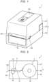
- FIG. 1 is a diagram illustrating an example of an outer appearance of a printer 1 in a standard state according to an embodiment.
- FIG. 2 is a diagram illustrating an example of an internal structure of the printer 1.
- the printer 1 is an example of a standard model printer, and includes a casing 2, a display operation portion 103, an open/close button 104, and a paper discharge port 105.
- the side where the paper discharge port 105 is provided is a front surface side of the printer 1, and a side opposite to a surface where the paper discharge port 105 is provided is a rear side.
- the casing 2 is a box-shaped container and includes an upper casing 21 and a lower casing 22.
- the upper casing 21 has a downward opening
- the lower casing 22 has an upward opening.
- the upper casing 21 is rotatable and attached to the lower casing 22 by a hinge 20 at the rear side. Accordingly, the upper casing 21 and the lower casing 22 are rotatable and connected, and open and close openings thereof as the upper casing 21 and lower casing 22 rotate.
- the hinge 20 is rotatable and connects the upper casing 21 and the lower casing 22 on the rear side.
- the hinge 20 includes a biasing member such as a torsion spring on one side of the lower casing 22 in the width direction.
- the biasing member biases the upper casing 21 in the direction in which the lower casing 22 is opened, so as to slow the movement of the upper casing 21 when closing the lower casing 22.
- a paper holding unit 3 (corresponding to the paper holding component ) and a printing unit 4 (corresponding to the printing component) are provided inside the casing 2 (corresponding to the box-shaped casing).
- the paper holding unit 3 is rotatable and holds a roll paper 30 in which a strip-shaped paper 31 is wrapped.
- the receipt roll is a roll wrapped by a strip-shaped receipt paper (an example of the paper 31).
- the receipt paper is a strip-shaped paper 31 that becomes a receipt by being printed and cut.
- the label roll is a roll wrapped by a strip-shaped label paper (an example of the paper 31).
- the label paper includes labels with a mount in which a label is pasted to a strip-shaped mount and labels without a mount. It is noted that the label has an adhesive layer provided on the rear side of the printed surface.
- the printing unit 4 prints on the paper 31 while conveying the paper 31 pulled out from the paper holding unit 3 and includes a print head 41 and a platen roller 42.
- the print head 41 is fixed to an inner surface of the upper casing 21 and is in close contact with the platen roller 42 with the upper casing 21 closing the opening on the upper surface of the lower casing 22.
- the print head 41 is, for example, a thermal head and includes a plurality of heating elements arranged in parallel.
- the print head 41 prints on the paper 31 interposed between the print head 41 and the platen roller 42 by using heat from a heating element.
- the platen roller 42 rotates by a driving force of the stepping motor being transmitted and conveys the paper 31 interposed between the platen roller 42 and the print head 41.
- the display operation portion 103 is provided on the upper surface of the upper casing 21.
- the display operation portion 103 receives input of various operations and displays various information.
- the open/close button 104 is provided in the front side of the side surface porn of the upper casing 21. If the open/close button 104 is pressed, a lock state of the structure holding the upper casing 21 at the position where the lower casing 22 is closed is released, the upper casing 21 is lifted according to the bias of the bias member, and the casing 2 is opened.
- a portion of the front surface of the lower casing 22 is configured with a front cover 23.
- the front cover 23 is an example of the cover portion.
- the other portions of the casing 2 except for the front cover 23 are an example of the main body portion.
- the paper discharge port 105 is an opening for issuing (discharging) printed matter such as a receipt (paper 31 after printing) and is provided between the upper end of the front cover 23 and the lower end of the front surface of the upper casing 21.
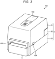
- FIG. 3 is a diagram illustrating an example of the outer appearance of a printer 101 with the cutting unit.
- the printer 1 illustrated in FIG. 1 of this embodiment is in the standard state.
- the cutting unit 6 is an example of an optional unit that performs predetermined processing on the paper 31.
- the front cover 23 of the printer 1 in the standard state is used by turning it over.
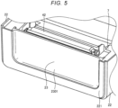
- FIGS. 4 to 8 are diagrams illustrating examples of a structure of a portion of the printer 1 including the front cover 23.
- FIG. 6 illustrates a state in which the lower casing 22 is removed from the state in FIGS. 4 and 5 .
- FIG. 7 illustrates the state in which the front cover 23 is removed from the state in FIG. 6 and turned over so that a supporting portion 232 (described later) faces up.
- FIG. 8 illustrates a state in which the front cover 23 with the supporting portion 232 tabulated is attached.
- the front cover 23 of the printer 1 in the standard state is attached to the frame 7 with a first surface 2301 facing the front surface.
- a front portion 221 of the lower casing 22 is formed into the U-shaped hollowed out shape, and the front cover 23 is arranged so as to be fitted into the hollowed out portion.
- the front cover 23 has attaching tabs 231 on both sides.
- the attaching tab 231 has the hole penetrating the shaft of the screw 238.
- the cylindrical screw receiving portion 71 is provided in the protruding manner at the position corresponding to the attaching tab 231 on the front surface of the frame 7 (refer to FIG. 7 ).
- the attaching tab 231 and the screw receiving portion 71 constitute an example of the attaching structure.
- the attaching structure is a structure for detachably attaching the front cover 23.
- any one of the first surface 2301 that is one surface of the plate-shaped front cover 23 and a second surface 2302 that is the other surface can be attached even in the direction facing the front surface.
- the above-mentioned attaching structure can allow the front cover 23 to be attached and detached by turning the inside and the outside of the front cover 23 inside out.
- the frame 7 supports portions built into the printer 1 and positions the portions at predetermined positions and is provided at a position hidden by the front portion 221 of the lower casing 22.
- the frame 7 is rotatable, supports, for example, both ends of the platen roller 42, and maintains the platen roller 42 at a predetermined position.
- the front cover 23 has a protrusion 233 (portions constituting the attaching structure) at two locations on the lower side portion (refer to FIG. 7 ).
- a groove-shaped recess 73 portion constituting the attaching structure is formed at the position in the frame 7 which the lower side of the front cover 23 is in contact with (refer to FIG. 8 ).
- the front cover 23 is fixed to the frame 7 by inserting the protrusion 233 into the recess 73, allowing the shaft of the screw 238 to penetrate the hole of the attaching tab 231, and being screwed into the screw receiving portion 71. From this state, if the screws 238 are removed and the front cover 23 separated from the frame 7 is turned over, the state illustrated in FIG. 7 is obtained. In this state, instead of the first surface 2301, the second surface 2302 which is the rear surface of the first surface 2301 faces the front surface.
- the supporting portion 232 is provided on the second surface 2302 of the front cover 23.
- the supporting portion 232 is the hook-shaped portion and supports the cutting unit 6 in the hooked state.
- the screw receiving portion 235 is provided on the second surface 2302 adjacent to the supporting portion 232.
- the screw receiving portion 235 is a portion of a deviation suppressing portion, and constitutes the deviation suppressing portion together with the screw 239, which will be described later.
- the direction in which the screws are inserted into the screw receiving portion 235 is from top to bottom. By this same movement from top to bottom, a hook portion 631 (refer to FIG. 9 , described later) provided in the cutting unit 6 is hooked and held by the supporting portion 232.
- FIG. 9 is an exploded perspective view illustrating an example of the structure of the cutting unit 6.
- FIG. 10 is a diagram illustrating an example of the structure of the portion of the printer with the cutting unit 101 including the front cover 23. It is noted that the cutting unit 6 illustrated in FIG. 9 is viewed from the rear side.
- the cutting unit 6 includes a drive portion 60, a fixed blade 61, a movable blade 62, a bracket 63, a cover 69, and the like.
- the drive unit 60 includes the motor, the link, and the like, and moves the movable blade 62 up and down.
- the fixed blade 61 cooperates with the movable blade 62 that moves up and down to interpose and cut the paper 31.
- the cutting unit 6 may perform full cut in which the paper 31 is cut across the entire width thereof or may perform partial cut in which a portion of the paper 31 in the width direction is left uncut. Furthermore, the manner of movement of the movable blade 62 moves with respect to the fixed blade 61 in the cutting unit 6 is not limited to vertical movement as in this embodiment.
- the bracket 63 is a plate-shaped member constituting the rear side of the drive unit 60 and being provided with a hook portion 631 and a protrusion 632.
- the hook portion 631 is an example of a supported portion.
- the hook portion 631 is an L-shaped portion protruding from the rear surface of the cutting unit 6 and being hooked onto the supporting portion 232.
- the hook portion 631 is formed, for example, by raising a portion of the metal plate constituting the rear surface of the cutting unit 6 at the substantially right angle from the rear surface and further bending a leading end portion at the substantially right angle.
- the protrusion 632 is a portion protruding downward from the lower portion of the metal plate constituting the rear surface of the cutting unit 6.
- the protrusion 632 is inserted into the recess 72 (refer to FIG. 8 ) provided in the frame 7.
- the recess 72 is provided at the position adjacent to the recess 73. By inserting the protrusion 632 into the recess 72, the lower portion of the cutting unit 6 is fixed to the frame 7.
- the cover 69 is an exterior of the cutting unit 6 covering the above-mentioned portions (drive portion 60, fixed blade 61, movable blade 62, bracket 63, and the like) and has a paper discharge port 605 formed therein.
- the paper discharge port 605 is located on an extension line along the traveling direction of the paper 31 discharged from the paper discharge port 105.
- the fixed blade 61 has a guide portion 615
- the bracket 63 has a guide portion 635.
- the guide portion 615 and the guide portion 635 are located upstream of the paper discharge port 605 and face the upper surface and the lower surface of the paper 31 to guide the paper 31 to the paper discharge port 605.
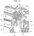
- FIGS. 11 and 12 are diagrams illustrating a support state of the cutting unit 6 by the supporting portion 232.
- FIG. 12 illustrates the state viewed diagonally downward from the position slightly higher than that in FIG. 11 .
- the hook portion 631 is supported in the state of being hooked by the supporting portion 232 by being positioned on the supporting portion 232 and being moved downward. After being hooked, since the hook portion 631 is hold down so that the hook portion 631 does not fall out from the supporting portion 232, the screw 239 is used.
- the screw 239 is a portion of the deviation suppressing portion and constitutes the deviation suppressing portion together with the above-mentioned screw receiving portion 235.
- the screw 239 is screwed into the screw receiving portion 235 provided adjacent to the supporting portion 232. This screwing direction is from top to bottom.
- the shaft portion of the screw 239 that has been screwed in is screwed into the screw receiving portion 235, and the head thereof is located above the screw receiving portion 235.
- the positions and dimensions of the hook portion 631, the supporting portion 232, and the screw receiving portion 235 are designed such that the head of the screw 239 screwed into the screw receiving portion 235 covers the end of the hook portion 631 hooked and supported by the supporting portion 232. Due to such positions and dimensions, the hook portion 631 hooked and supported by the supporting portion 232 is pressed at least at the end of the hook portion 631 by the head of the screw 239. Accordingly, if the screw 239 is screwed into the screw receiving portion 235, since the hook portion 631 cannot be moved upward, the hook portion 631 does not come off from the supporting portion 232.
- the printer 101 with the cutting unit is configured by covering it again with the lower casing 22. It is noted that, when removing the cutting unit 6 from the printer 1, the above-mentioned procedure is reversed. That is, the lower casing 22 is peeled off to expose the frame 7, the cutting unit 6 is removed by removing the screws 239, the front cover 23 is removed except for the screws 238, turned over and reattached, and the lower casing 22 is recovered.
- FIG. 13 is a diagram illustrating the peeling unit 8 and the positional relationship of the peeling unit 8 with respect to the frame 7.
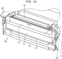
- FIG. 14 is a diagram illustrating an example of the printer 102 with the peeling unit, with the lower casing 22 removed.
- the peeling unit 8 is another example of an optional unit.
- the peeling unit 8 is used if the paper 31 is a strip-shaped mount with the label pasted thereon, and if it is desired to issue the label that is peeled off from the mount. In other words, the peeling unit 8 peels the label from the mount as the label is conveyed after printing.
- the peeling unit 8 has a first member 81 and a second member 82.
- the first member 81 is provided adjacent to the downstream side of the platen roller 42, the second member 82 is a portion fixed to the frame 7, and is rotatable and supports the first member 81.
- the rotation direction of the first member 81 is the direction in which the first member 81 approaches and separates from the platen roller 42, and as the first member 81 rotates, the first member 81 moves between the position close to the platen roller 42 and the position away from the platen roller 42.
- the axis of rotation is substantially parallel to the platen roller 42.
- the first member 81 interposes the mount between the first member 81 and the platen roller 42 at the position close to the platen roller 42.
- the leading end of the mount is taken outside the casing 2 from between a mount discharge port 83 which is the gap between the first member 81 and the second member 82.
- the first member 81 includes a label receiving portion 811 supporting the peeled label from below.
- the label receiving portion 811 is a surface that is processed to prevent the adhesive surface of the label from sticking (such as forming unevenness or coating with fluororesin).
- the second member 82 has the attaching tabs 821 at both ends in the width direction.
- the attaching tab 821 is provided at the position corresponding to the screw receiving portion 71 of the frame 7 and has the hole which the shaft portion of the screw 238 penetrates.
- the second member 82 is fixed to the frame 7 by the shaft portion of the screw 238 penetrating the hole in the attaching tab 821 and being screwed into the screw receiving portion 71.
- the second member 82 has a downwardly protruding protrusion at its lower portion.
- This protrusion is a portion corresponding to the protrusion 632 of the cutting unit 6 and is inserted into the recess 72 (refer to FIG. 8 ) provided in the frame 7.
- the protrusion of the peeling unit 8 is fixed to the frame 7.
- the structure for enabling the cutting unit 6 to be detachable can be realized by the front cover 23 and the surroundings constituting a portion of the casing 2 of the standard model printer 1.
- a simple support state where the supported portion (hook portion 631) provided on the optional unit is hooked to the hook-shaped supporting portion 232 provided on one surface of the front cover 23 can be suppressed from being unexpectedly released due to misalignment.
- the deviation suppressing portion is configured with the screw receiving portion 235 and the screw 239, the simple structure is easy to install, and the installation space can be reduced.
Landscapes
- Life Sciences & Earth Sciences (AREA)
- Forests & Forestry (AREA)
- Engineering & Computer Science (AREA)
- Mechanical Engineering (AREA)
- Accessory Devices And Overall Control Thereof (AREA)
- Handling Of Sheets (AREA)
Abstract
Description
- Embodiments described herein relate generally to printers.
- In the related art, printers have been used to print on a paper drawn from a roll paper and issue the printed paper (for example, Patent Literature 1). For such printers, a standard model is a model in which the paper outputs in a strip shape without cutting or peeling, and in some cases, the selling method that is to provide functions such as cutting and peeling as an option that can be attached to the standard model may be taken.
- If a plurality of models are developed using the method described above, a structure is required to enable options to be attached and detached. The members realizing this structure are generally prepared separately, together with optional units, rather than as necessary members to enable a standard model printer to function.
- It is not preferable if there are members that need to be prepared separately in addition to the optional units, because the cost of materials and the cost requiring the manufacturing increase, and the management of the members is also required.
- To this end, a printer according to appended claims is provided.
-
-
FIG. 1 is a diagram illustrating an example of an outer appearance of a printer in a standard state according to an embodiment; -
FIG. 2 is a diagram illustrating an example of an internal structure of the printer; -
FIG. 3 is a diagram illustrating an example of the outer appearance of the printer with a cutting unit; -
FIG. 4 is a diagram illustrating an example of a structure of a portion of the printer including the front cover; -
FIG. 5 is a diagram illustrating an example of a structure of a portion of the printer including a front cover; -
FIG. 6 is a diagram illustrating a state illustrated inFIGS. 4 and5 with a casing removed; -
FIG. 7 is a diagram illustrating a state in which the front cover is removed from the state illustrated inFIG. 6 and turned over so that a supporting portion faces outward; -
FIG. 8 is a diagram illustrating a state in which the front cover with the supporting portion tabulated is attached; -
FIG. 9 is an exploded perspective view illustrating an example of a structure of the cutting unit; -
FIG. 10 is a diagram illustrating an example of a structure of a portion including the front cover of the printer with the cutting unit; -
FIG. 11 is a diagram illustrating a state in which the cutting unit is supported by the supporting portion; -
FIG. 12 is a diagram illustrating a state in which the cutting unit is supported by the supporting portion; -
FIG. 13 is a diagram illustrating a positional relationship with respect to a peeling unit and a frame of the peeling unit; and -
FIG. 14 is a diagram illustrating an example of a printer with a peeling unit, in a state of the lower casing removed. - The problem to be solved by the present invention is to provide a printer which can realize a structure of enabling a unit for providing optional functions to be detachable with a structure included in a standard model.
- In general, according to one embodiment, a printer includes: a paper holding unit holding a roll paper wrapped in a strip-shaped paper; a printing unit printing on the paper pulled out from the paper holding unit; and a box-shaped casing housing the paper holding unit and the printing unit, wherein the casing includes: a plate-shaped cover portion constituting at least a portion of a surface provided with a paper discharge port for discharging the paper after printing; and a main body portion being a portion other than the cover portion, wherein, in an attaching structure in which the cover portion is detachably attached to the main body portion, the cover portion can be attached in any direction where one of a first surface being one surface of the plate-shaped cover portion and a second surface being the other surface in a direction faces the main body portion, and wherein the cover portion has a supporting portion detachably supporting an optional unit performing a predetermined process on the paper in any one of the first surface or the second surface.
- Embodiments will be described with reference to the drawings.
FIG. 1 is a diagram illustrating an example of an outer appearance of a printer 1 in a standard state according to an embodiment.FIG. 2 is a diagram illustrating an example of an internal structure of the printer 1. - The printer 1 is an example of a standard model printer, and includes a
casing 2, adisplay operation portion 103, an open/close button 104, and apaper discharge port 105. The side where thepaper discharge port 105 is provided is a front surface side of the printer 1, and a side opposite to a surface where thepaper discharge port 105 is provided is a rear side. - The
casing 2 is a box-shaped container and includes anupper casing 21 and alower casing 22. Theupper casing 21 has a downward opening, and thelower casing 22 has an upward opening. Theupper casing 21 is rotatable and attached to thelower casing 22 by ahinge 20 at the rear side. Accordingly, theupper casing 21 and thelower casing 22 are rotatable and connected, and open and close openings thereof as theupper casing 21 andlower casing 22 rotate. - The
hinge 20 is rotatable and connects theupper casing 21 and thelower casing 22 on the rear side. Thehinge 20 includes a biasing member such as a torsion spring on one side of thelower casing 22 in the width direction. The biasing member biases theupper casing 21 in the direction in which thelower casing 22 is opened, so as to slow the movement of theupper casing 21 when closing thelower casing 22. - A paper holding unit 3 (corresponding to the paper holding component ) and a printing unit 4 (corresponding to the printing component) are provided inside the casing 2 (corresponding to the box-shaped casing). The
paper holding unit 3 is rotatable and holds aroll paper 30 in which a strip-shaped paper 31 is wrapped. - As the
roll paper 30, a receipt roll and a label roll may be exemplified. The receipt roll is a roll wrapped by a strip-shaped receipt paper (an example of the paper 31). The receipt paper is a strip-shaped paper 31 that becomes a receipt by being printed and cut. - The label roll is a roll wrapped by a strip-shaped label paper (an example of the paper 31). The label paper includes labels with a mount in which a label is pasted to a strip-shaped mount and labels without a mount. It is noted that the label has an adhesive layer provided on the rear side of the printed surface.
- The
printing unit 4 prints on thepaper 31 while conveying thepaper 31 pulled out from thepaper holding unit 3 and includes aprint head 41 and aplaten roller 42. Theprint head 41 is fixed to an inner surface of theupper casing 21 and is in close contact with theplaten roller 42 with theupper casing 21 closing the opening on the upper surface of thelower casing 22. - The
print head 41 is, for example, a thermal head and includes a plurality of heating elements arranged in parallel. Theprint head 41 prints on thepaper 31 interposed between theprint head 41 and theplaten roller 42 by using heat from a heating element. Theplaten roller 42 rotates by a driving force of the stepping motor being transmitted and conveys thepaper 31 interposed between theplaten roller 42 and theprint head 41. - The
display operation portion 103 is provided on the upper surface of theupper casing 21. Thedisplay operation portion 103 receives input of various operations and displays various information. The open/close button 104 is provided in the front side of the side surface porn of theupper casing 21. If the open/close button 104 is pressed, a lock state of the structure holding theupper casing 21 at the position where thelower casing 22 is closed is released, theupper casing 21 is lifted according to the bias of the bias member, and thecasing 2 is opened. - A portion of the front surface of the
lower casing 22 is configured with afront cover 23. Thefront cover 23 is an example of the cover portion. In addition, the other portions of thecasing 2 except for thefront cover 23 are an example of the main body portion. - The
paper discharge port 105 is an opening for issuing (discharging) printed matter such as a receipt (paper 31 after printing) and is provided between the upper end of thefront cover 23 and the lower end of the front surface of theupper casing 21. -
FIG. 3 is a diagram illustrating an example of the outer appearance of aprinter 101 with the cutting unit. The printer 1 illustrated inFIG. 1 of this embodiment is in the standard state. By attaching thecutting unit 6 to the front surface of the printer 1 in the standard state, theprinter 101 with the cutting unit can be obtained. Thecutting unit 6 is an example of an optional unit that performs predetermined processing on thepaper 31. To attach thecutting unit 6, thefront cover 23 of the printer 1 in the standard state is used by turning it over. -
FIGS. 4 to 8 are diagrams illustrating examples of a structure of a portion of the printer 1 including thefront cover 23.FIG. 6 illustrates a state in which thelower casing 22 is removed from the state inFIGS. 4 and5 . In addition,FIG. 7 illustrates the state in which thefront cover 23 is removed from the state inFIG. 6 and turned over so that a supporting portion 232 (described later) faces up.FIG. 8 illustrates a state in which thefront cover 23 with the supportingportion 232 tabulated is attached. - The
front cover 23 of the printer 1 in the standard state is attached to theframe 7 with afirst surface 2301 facing the front surface. Afront portion 221 of thelower casing 22 is formed into the U-shaped hollowed out shape, and thefront cover 23 is arranged so as to be fitted into the hollowed out portion. - The
front cover 23 has attachingtabs 231 on both sides. The attachingtab 231 has the hole penetrating the shaft of thescrew 238. Furthermore, the cylindricalscrew receiving portion 71 is provided in the protruding manner at the position corresponding to the attachingtab 231 on the front surface of the frame 7 (refer toFIG. 7 ). - The attaching
tab 231 and thescrew receiving portion 71 constitute an example of the attaching structure. The attaching structure is a structure for detachably attaching thefront cover 23. In this attaching structure, any one of thefirst surface 2301 that is one surface of the plate-shapedfront cover 23 and asecond surface 2302 that is the other surface can be attached even in the direction facing the front surface. In other words, the above-mentioned attaching structure can allow thefront cover 23 to be attached and detached by turning the inside and the outside of thefront cover 23 inside out. - It is noted that the
frame 7 supports portions built into the printer 1 and positions the portions at predetermined positions and is provided at a position hidden by thefront portion 221 of thelower casing 22. Theframe 7 is rotatable, supports, for example, both ends of theplaten roller 42, and maintains theplaten roller 42 at a predetermined position. - In addition, the
front cover 23 has a protrusion 233 (portions constituting the attaching structure) at two locations on the lower side portion (refer toFIG. 7 ). In addition, a groove-shaped recess 73 (portion constituting the attaching structure) is formed at the position in theframe 7 which the lower side of thefront cover 23 is in contact with (refer toFIG. 8 ). By inserting theprotrusion 233 into therecess 73, the lower side of thefront cover 23 is fixed to theframe 7. - As illustrated in
FIG. 6 , thefront cover 23 is fixed to theframe 7 by inserting theprotrusion 233 into therecess 73, allowing the shaft of thescrew 238 to penetrate the hole of the attachingtab 231, and being screwed into thescrew receiving portion 71. From this state, if thescrews 238 are removed and thefront cover 23 separated from theframe 7 is turned over, the state illustrated inFIG. 7 is obtained. In this state, instead of thefirst surface 2301, thesecond surface 2302 which is the rear surface of thefirst surface 2301 faces the front surface. In addition, from this state, if theprotrusion 233 is inserted into therecess 73, thefront cover 23 is superimposed on theframe 7, and if the attachingtab 231 is fixed to thescrew receiving portion 71 with thescrew 238, the state illustrated inFIG. 8 is obtained. - The supporting
portion 232 is provided on thesecond surface 2302 of thefront cover 23. The supportingportion 232 is the hook-shaped portion and supports thecutting unit 6 in the hooked state. In addition, thescrew receiving portion 235 is provided on thesecond surface 2302 adjacent to the supportingportion 232. Thescrew receiving portion 235 is a portion of a deviation suppressing portion, and constitutes the deviation suppressing portion together with thescrew 239, which will be described later. The direction in which the screws are inserted into thescrew receiving portion 235 is from top to bottom. By this same movement from top to bottom, a hook portion 631 (refer toFIG. 9 , described later) provided in thecutting unit 6 is hooked and held by the supportingportion 232. -
FIG. 9 is an exploded perspective view illustrating an example of the structure of thecutting unit 6.FIG. 10 is a diagram illustrating an example of the structure of the portion of the printer with thecutting unit 101 including thefront cover 23. It is noted that thecutting unit 6 illustrated inFIG. 9 is viewed from the rear side. - The
cutting unit 6 includes adrive portion 60, a fixedblade 61, amovable blade 62, abracket 63, acover 69, and the like. Thedrive unit 60 includes the motor, the link, and the like, and moves themovable blade 62 up and down. The fixedblade 61 cooperates with themovable blade 62 that moves up and down to interpose and cut thepaper 31. - It is noted that the
cutting unit 6 may perform full cut in which thepaper 31 is cut across the entire width thereof or may perform partial cut in which a portion of thepaper 31 in the width direction is left uncut. Furthermore, the manner of movement of themovable blade 62 moves with respect to the fixedblade 61 in thecutting unit 6 is not limited to vertical movement as in this embodiment. - The
bracket 63 is a plate-shaped member constituting the rear side of thedrive unit 60 and being provided with ahook portion 631 and aprotrusion 632. Thehook portion 631 is an example of a supported portion. - The
hook portion 631 is an L-shaped portion protruding from the rear surface of thecutting unit 6 and being hooked onto the supportingportion 232. Thehook portion 631 is formed, for example, by raising a portion of the metal plate constituting the rear surface of thecutting unit 6 at the substantially right angle from the rear surface and further bending a leading end portion at the substantially right angle. - The
protrusion 632 is a portion protruding downward from the lower portion of the metal plate constituting the rear surface of thecutting unit 6. Theprotrusion 632 is inserted into the recess 72 (refer toFIG. 8 ) provided in theframe 7. Therecess 72 is provided at the position adjacent to therecess 73. By inserting theprotrusion 632 into therecess 72, the lower portion of thecutting unit 6 is fixed to theframe 7. - The
cover 69 is an exterior of thecutting unit 6 covering the above-mentioned portions (driveportion 60, fixedblade 61,movable blade 62,bracket 63, and the like) and has apaper discharge port 605 formed therein. Thepaper discharge port 605 is located on an extension line along the traveling direction of thepaper 31 discharged from thepaper discharge port 105. - It is noted that the fixed
blade 61 has aguide portion 615, and thebracket 63 has aguide portion 635. Theguide portion 615 and theguide portion 635 are located upstream of thepaper discharge port 605 and face the upper surface and the lower surface of thepaper 31 to guide thepaper 31 to thepaper discharge port 605. -
FIGS. 11 and12 are diagrams illustrating a support state of thecutting unit 6 by the supportingportion 232.FIG. 12 illustrates the state viewed diagonally downward from the position slightly higher than that inFIG. 11 . - The
hook portion 631 is supported in the state of being hooked by the supportingportion 232 by being positioned on the supportingportion 232 and being moved downward. After being hooked, since thehook portion 631 is hold down so that thehook portion 631 does not fall out from the supportingportion 232, thescrew 239 is used. Thescrew 239 is a portion of the deviation suppressing portion and constitutes the deviation suppressing portion together with the above-mentionedscrew receiving portion 235. Thescrew 239 is screwed into thescrew receiving portion 235 provided adjacent to the supportingportion 232. This screwing direction is from top to bottom. The shaft portion of thescrew 239 that has been screwed in is screwed into thescrew receiving portion 235, and the head thereof is located above thescrew receiving portion 235. - The positions and dimensions of the
hook portion 631, the supportingportion 232, and thescrew receiving portion 235 are designed such that the head of thescrew 239 screwed into thescrew receiving portion 235 covers the end of thehook portion 631 hooked and supported by the supportingportion 232. Due to such positions and dimensions, thehook portion 631 hooked and supported by the supportingportion 232 is pressed at least at the end of thehook portion 631 by the head of thescrew 239. Accordingly, if thescrew 239 is screwed into thescrew receiving portion 235, since thehook portion 631 cannot be moved upward, thehook portion 631 does not come off from the supportingportion 232. - As described above, after the
cutting unit 6 is attached to theframe 7, theprinter 101 with the cutting unit is configured by covering it again with thelower casing 22. It is noted that, when removing thecutting unit 6 from the printer 1, the above-mentioned procedure is reversed. That is, thelower casing 22 is peeled off to expose theframe 7, thecutting unit 6 is removed by removing thescrews 239, thefront cover 23 is removed except for thescrews 238, turned over and reattached, and thelower casing 22 is recovered. -
FIG. 13 is a diagram illustrating thepeeling unit 8 and the positional relationship of thepeeling unit 8 with respect to theframe 7.FIG. 14 is a diagram illustrating an example of theprinter 102 with the peeling unit, with thelower casing 22 removed. - The
peeling unit 8 is another example of an optional unit. Thepeeling unit 8 is used if thepaper 31 is a strip-shaped mount with the label pasted thereon, and if it is desired to issue the label that is peeled off from the mount. In other words, thepeeling unit 8 peels the label from the mount as the label is conveyed after printing. - The
peeling unit 8 has afirst member 81 and asecond member 82. Thefirst member 81 is provided adjacent to the downstream side of theplaten roller 42, thesecond member 82 is a portion fixed to theframe 7, and is rotatable and supports thefirst member 81. The rotation direction of thefirst member 81 is the direction in which thefirst member 81 approaches and separates from theplaten roller 42, and as thefirst member 81 rotates, thefirst member 81 moves between the position close to theplaten roller 42 and the position away from theplaten roller 42. The axis of rotation is substantially parallel to theplaten roller 42. - The
first member 81 interposes the mount between thefirst member 81 and theplaten roller 42 at the position close to theplaten roller 42. The leading end of the mount is taken outside thecasing 2 from between amount discharge port 83 which is the gap between thefirst member 81 and thesecond member 82. In addition, thefirst member 81 includes alabel receiving portion 811 supporting the peeled label from below. Thelabel receiving portion 811 is a surface that is processed to prevent the adhesive surface of the label from sticking (such as forming unevenness or coating with fluororesin). - When attaching this
peeling unit 8 to theframe 7, thefront cover 23 is unnecessary, and thus is removed. - The
second member 82 has the attachingtabs 821 at both ends in the width direction. The attachingtab 821 is provided at the position corresponding to thescrew receiving portion 71 of theframe 7 and has the hole which the shaft portion of thescrew 238 penetrates. Thesecond member 82 is fixed to theframe 7 by the shaft portion of thescrew 238 penetrating the hole in the attachingtab 821 and being screwed into thescrew receiving portion 71. - It is noted that the
second member 82 has a downwardly protruding protrusion at its lower portion. This protrusion is a portion corresponding to theprotrusion 632 of thecutting unit 6 and is inserted into the recess 72 (refer toFIG. 8 ) provided in theframe 7. By inserting the protrusion of thepeeling unit 8 into therecess 72, the lower portion of thepeeling unit 8 is fixed to theframe 7. - As described above, according to the printer 1 of this embodiment, the structure for enabling the
cutting unit 6 to be detachable can be realized by thefront cover 23 and the surroundings constituting a portion of thecasing 2 of the standard model printer 1. - In addition, according to the present embodiment, by providing the deviation suppressing portion, a simple support state where the supported portion (hook portion 631) provided on the optional unit is hooked to the hook-shaped supporting
portion 232 provided on one surface of thefront cover 23 can be suppressed from being unexpectedly released due to misalignment. - In addition, according to the present embodiment, since the deviation suppressing portion is configured with the
screw receiving portion 235 and thescrew 239, the simple structure is easy to install, and the installation space can be reduced. - While certain embodiments have been described, these embodiments have been presented by way of example only, and are not intended to limit the scope of the inventions. Indeed, the novel embodiments described herein may be embodied in a variety of other forms; furthermore, various omissions, substitutions and changes in the form of the embodiments described herein may be made without departing from the scope of the inventions. The accompanying claims and their equivalents are intended to cover such forms or modifications as would fall within the scope of the inventions.
Claims (12)
- A printer, comprising:a paper holding component (3) holding a roll paper wrapped in a strip-shaped paper;a printing component (4) printing on the roll paper pulled out from the paper holding component; anda box-shaped casing (2) housing the paper holding component and the printing component,wherein the box-shaped casing includes:a plate-shaped cover (23)portion constituting at least a portion of a surface provided with a paper discharge port for discharging the roll paper after printing; anda main body portion being a portion other than the cover portion,wherein, in an attaching structure in which the cover portion is detachably attached to the main body portion, the cover portion is configured to be attached in any direction where one of a first surface being one surface of the plate-shaped cover portion and a second surface being an other surface in a direction faces the main body portion, andwherein the cover portion has a supporting portion detachably supporting an optional component performing a predetermined process on the roll paper in one of the first surface or the second surface.
- The printer according to claim 1,wherein the supporting portion has a hook-like shape,wherein the optional component has a supported portion having the hook-like shape supported in a state of being hooked by the supporting portion, andwherein a deviation suppressing portion for suppressing deviation due to movement in a direction of releasing the hook-like state between the supporting portion and the supported portion is further provided adjacent to the supporting portion.
- The printer according to claim 2,wherein the deviation suppressing portion is configured with a screw and a screw receiving portion into which the screw is screwed, andwherein a head of the screw screwed into the screw receiving portion is located at a position being in contact with the supported portion supported in the state of being hooked by the supporting portion and preventing movement of the supported portion.
- The printer according to claim 3,
wherein the screwing direction of the screw into the screw receiving portion is a direction substantially opposite to a moving direction if the supported portion hooked on the supporting portion moves away from the supporting portion. - The printer according to any one of claims 1 to 4, wherein the optional component performs a cutting process on the roll paper.
- The printer according to any one of claims 1 to 5, wherein the optional component is a cutting component including a driver, a fixed blade, a movable blade, a bracket, a cover, and the like.
- The printer according to claim 6, wherein the driver moves the movable blade up and down.
- The printer according to claim 6 or 7, wherein the fixed blade is configured to cooperate with the movable blade that moves up and down to interpose and cut the paper.
- The printer according to any one of claims 1 to 8, wherein the cutting component performs a full cut in which the roll paper is cut across an entire width thereof.
- The printer according to any one of claims 1 to 9, wherein the cutting component performs a partial cut in which a portion of the roll paper in the width direction is left uncut.
- The printer according to any one of claims 1 to 10, wherein the optional component performs peeling a label from a mount as the label is conveyed after printing.
- The printer according to any one of claims 1 to 11, wherein the printing component is a thermal printing component.
Applications Claiming Priority (1)
| Application Number | Priority Date | Filing Date | Title |
|---|---|---|---|
| JP2023048194A JP7828917B2 (en) | 2023-03-24 | 2023-03-24 | printer |
Publications (2)
| Publication Number | Publication Date |
|---|---|
| EP4434760A1 true EP4434760A1 (en) | 2024-09-25 |
| EP4434760B1 EP4434760B1 (en) | 2026-05-06 |
Family
ID=90038244
Family Applications (1)
| Application Number | Title | Priority Date | Filing Date |
|---|---|---|---|
| EP24158931.6A Active EP4434760B1 (en) | 2023-03-24 | 2024-02-21 | Printer |
Country Status (3)
| Country | Link |
|---|---|
| EP (1) | EP4434760B1 (en) |
| JP (1) | JP7828917B2 (en) |
| CN (1) | CN118683198A (en) |
Families Citing this family (1)
| Publication number | Priority date | Publication date | Assignee | Title |
|---|---|---|---|---|
| USD1018659S1 (en) * | 2022-02-24 | 2024-03-19 | Zebra Technologies Corporation | Printer |
Citations (2)
| Publication number | Priority date | Publication date | Assignee | Title |
|---|---|---|---|---|
| US20070003354A1 (en) * | 2005-06-06 | 2007-01-04 | Toshiba Tec Kabushiki Kaisha | Printer |
| US20200130383A1 (en) * | 2017-09-26 | 2020-04-30 | Sato Holdings Kabushiki Kaisha | Printer |
Family Cites Families (10)
| Publication number | Priority date | Publication date | Assignee | Title |
|---|---|---|---|---|
| JP2002208784A (en) | 2001-01-11 | 2002-07-26 | Sharp Corp | Exterior cover of device and method of forming functional opening in exterior cover |
| JP4090935B2 (en) | 2003-04-17 | 2008-05-28 | シャープ株式会社 | Exterior cover, image forming apparatus including the same, and control system |
| US7914218B2 (en) * | 2006-06-29 | 2011-03-29 | Toshiba Tec Kabushiki Kaisha | Thermal printer and printing device |
| JP5611887B2 (en) * | 2011-04-28 | 2014-10-22 | スター精密株式会社 | Printer |
| KR101263651B1 (en) * | 2011-10-25 | 2013-05-21 | 주식회사 신흥정밀 | Printer with printing paper cutting device |
| JP6422333B2 (en) * | 2014-09-02 | 2018-11-14 | セイコーインスツル株式会社 | Printing unit and printer |
| JP6894790B2 (en) * | 2017-07-24 | 2021-06-30 | 東芝テック株式会社 | Printer |
| JP6967925B2 (en) | 2017-09-26 | 2021-11-17 | サトーホールディングス株式会社 | Printer |
| JP6697058B1 (en) * | 2018-12-05 | 2020-05-20 | シチズン時計株式会社 | Printer |
| CN210759839U (en) | 2019-08-09 | 2020-06-16 | 山东新北洋信息技术股份有限公司 | Printer and printing method |
-
2023
- 2023-03-24 JP JP2023048194A patent/JP7828917B2/en active Active
-
2024
- 2024-01-18 CN CN202410075025.1A patent/CN118683198A/en active Pending
- 2024-02-21 EP EP24158931.6A patent/EP4434760B1/en active Active
Patent Citations (2)
| Publication number | Priority date | Publication date | Assignee | Title |
|---|---|---|---|---|
| US20070003354A1 (en) * | 2005-06-06 | 2007-01-04 | Toshiba Tec Kabushiki Kaisha | Printer |
| US20200130383A1 (en) * | 2017-09-26 | 2020-04-30 | Sato Holdings Kabushiki Kaisha | Printer |
Also Published As
| Publication number | Publication date |
|---|---|
| CN118683198A (en) | 2024-09-24 |
| JP7828917B2 (en) | 2026-03-12 |
| EP4434760B1 (en) | 2026-05-06 |
| JP2024136893A (en) | 2024-10-04 |
Similar Documents
| Publication | Publication Date | Title |
|---|---|---|
| JP4868450B2 (en) | Printer | |
| EP1698476B1 (en) | Tape printer | |
| EP3138694B1 (en) | Printer | |
| EP1731275B1 (en) | Printer with cutter | |
| EP1674273B1 (en) | Tape printer | |
| EP3251865B1 (en) | Printer | |
| EP2241443B1 (en) | Thermal printer | |
| CN108602364B (en) | printer | |
| JP4694633B2 (en) | Printing device | |
| EP4434760B1 (en) | Printer | |
| EP1516737B1 (en) | Thermal printer | |
| US12611877B2 (en) | Printer | |
| CN105459617B (en) | Print unit and printer | |
| EP3228470B1 (en) | Printer | |
| JP2008094009A (en) | Printing device | |
| JP2025122228A (en) | printer | |
| JP4033073B2 (en) | Tape printer | |
| CN114683712B (en) | Printing apparatus | |
| JP4997337B2 (en) | Printing device | |
| JP7815760B2 (en) | printing device | |
| CN114683713B (en) | Printing device | |
| JP7782539B2 (en) | Tape cartridge and method of manufacturing the tape cartridge | |
| JP7800133B2 (en) | printing device | |
| JP7668170B2 (en) | Printer | |
| EP4438315A1 (en) | Printer and sheet support device |
Legal Events
| Date | Code | Title | Description |
|---|---|---|---|
| PUAI | Public reference made under article 153(3) epc to a published international application that has entered the european phase |
Free format text: ORIGINAL CODE: 0009012 |
|
| STAA | Information on the status of an ep patent application or granted ep patent |
Free format text: STATUS: THE APPLICATION HAS BEEN PUBLISHED |
|
| AK | Designated contracting states |
Kind code of ref document: A1 Designated state(s): AL AT BE BG CH CY CZ DE DK EE ES FI FR GB GR HR HU IE IS IT LI LT LU LV MC ME MK MT NL NO PL PT RO RS SE SI SK SM TR |
|
| STAA | Information on the status of an ep patent application or granted ep patent |
Free format text: STATUS: REQUEST FOR EXAMINATION WAS MADE |
|
| 17P | Request for examination filed |
Effective date: 20250325 |
|
| GRAP | Despatch of communication of intention to grant a patent |
Free format text: ORIGINAL CODE: EPIDOSNIGR1 |
|
| STAA | Information on the status of an ep patent application or granted ep patent |
Free format text: STATUS: GRANT OF PATENT IS INTENDED |
|
| INTG | Intention to grant announced |
Effective date: 20251125 |
|
| GRAS | Grant fee paid |
Free format text: ORIGINAL CODE: EPIDOSNIGR3 |
|
| GRAA | (expected) grant |
Free format text: ORIGINAL CODE: 0009210 |
|
| STAA | Information on the status of an ep patent application or granted ep patent |
Free format text: STATUS: THE PATENT HAS BEEN GRANTED |
|
| AK | Designated contracting states |
Kind code of ref document: B1 Designated state(s): AL AT BE BG CH CY CZ DE DK EE ES FI FR GB GR HR HU IE IS IT LI LT LU LV MC ME MK MT NL NO PL PT RO RS SE SI SK SM TR |
|
| REG | Reference to a national code |
Ref country code: CH Ref legal event code: F10 Free format text: ST27 STATUS EVENT CODE: U-0-0-F10-F00 (AS PROVIDED BY THE NATIONAL OFFICE) Effective date: 20260506 Ref country code: GB Ref legal event code: FG4D |
|
| REG | Reference to a national code |
Ref country code: DE Ref legal event code: R096 Ref document number: 602024004483 Country of ref document: DE |
|
| REG | Reference to a national code |
Ref country code: IE Ref legal event code: FG4D |