EP4434756A1 - Printer - Google Patents
Printer Download PDFInfo
- Publication number
- EP4434756A1 EP4434756A1 EP24165114.0A EP24165114A EP4434756A1 EP 4434756 A1 EP4434756 A1 EP 4434756A1 EP 24165114 A EP24165114 A EP 24165114A EP 4434756 A1 EP4434756 A1 EP 4434756A1
- Authority
- EP
- European Patent Office
- Prior art keywords
- midstream
- linerless label
- label
- downstream
- ribs
- Prior art date
- Legal status (The legal status is an assumption and is not a legal conclusion. Google has not performed a legal analysis and makes no representation as to the accuracy of the status listed.)
- Granted
Links
Images


Classifications
-
- B—PERFORMING OPERATIONS; TRANSPORTING
- B41—PRINTING; LINING MACHINES; TYPEWRITERS; STAMPS
- B41J—TYPEWRITERS; SELECTIVE PRINTING MECHANISMS, i.e. MECHANISMS PRINTING OTHERWISE THAN FROM A FORME; CORRECTION OF TYPOGRAPHICAL ERRORS
- B41J2/00—Typewriters or selective printing mechanisms characterised by the printing or marking process for which they are designed
- B41J2/315—Typewriters or selective printing mechanisms characterised by the printing or marking process for which they are designed characterised by selective application of heat to a heat sensitive printing or impression-transfer material
- B41J2/32—Typewriters or selective printing mechanisms characterised by the printing or marking process for which they are designed characterised by selective application of heat to a heat sensitive printing or impression-transfer material using thermal heads
-
- B—PERFORMING OPERATIONS; TRANSPORTING
- B41—PRINTING; LINING MACHINES; TYPEWRITERS; STAMPS
- B41J—TYPEWRITERS; SELECTIVE PRINTING MECHANISMS, i.e. MECHANISMS PRINTING OTHERWISE THAN FROM A FORME; CORRECTION OF TYPOGRAPHICAL ERRORS
- B41J29/00—Details of, or accessories for, typewriters or selective printing mechanisms not otherwise provided for
- B41J29/38—Drives, motors, controls or automatic cut-off devices for the entire printing mechanism
-
- B—PERFORMING OPERATIONS; TRANSPORTING
- B41—PRINTING; LINING MACHINES; TYPEWRITERS; STAMPS
- B41J—TYPEWRITERS; SELECTIVE PRINTING MECHANISMS, i.e. MECHANISMS PRINTING OTHERWISE THAN FROM A FORME; CORRECTION OF TYPOGRAPHICAL ERRORS
- B41J3/00—Typewriters or selective printing or marking mechanisms characterised by the purpose for which they are constructed
- B41J3/407—Typewriters or selective printing or marking mechanisms characterised by the purpose for which they are constructed for marking on special material
- B41J3/4075—Tape printers; Label printers
-
- B—PERFORMING OPERATIONS; TRANSPORTING
- B65—CONVEYING; PACKING; STORING; HANDLING THIN OR FILAMENTARY MATERIAL
- B65H—HANDLING THIN OR FILAMENTARY MATERIAL, e.g. SHEETS, WEBS, CABLES
- B65H18/00—Winding webs
- B65H18/08—Web-winding mechanisms
- B65H18/26—Mechanisms for controlling contact pressure on winding-web package, e.g. for regulating the quantity of air between web layers
-
- B—PERFORMING OPERATIONS; TRANSPORTING
- B65—CONVEYING; PACKING; STORING; HANDLING THIN OR FILAMENTARY MATERIAL
- B65H—HANDLING THIN OR FILAMENTARY MATERIAL, e.g. SHEETS, WEBS, CABLES
- B65H3/00—Separating articles from piles
- B65H3/66—Article guides or smoothers, e.g. movable in operation
-
- B—PERFORMING OPERATIONS; TRANSPORTING
- B65—CONVEYING; PACKING; STORING; HANDLING THIN OR FILAMENTARY MATERIAL
- B65H—HANDLING THIN OR FILAMENTARY MATERIAL, e.g. SHEETS, WEBS, CABLES
- B65H2553/00—Sensing or detecting means
- B65H2553/80—Arangement of the sensing means
- B65H2553/82—Arangement of the sensing means with regard to the direction of transport of the handled material
Definitions
- the present invention relates to a printer.
- a thermal printer that operates as follows. Under a state in which a recording sheet is sandwiched between a platen roller and a thermal head, the platen roller is rotated, and thus printing is performed by the thermal head on a print surface of the recording sheet while the recording sheet is conveyed.
- a so-called linerless label is used as a recording sheet in some cases.
- the linerless label is a recording sheet without a liner configured to cover a pressure-sensitive adhesive surface formed opposite to a print surface of the recording sheet.
- the labels delivered from the printer may stick to unintended places such as an outer surface of the printer or a periphery of the printer, which may interfere with delivery of the labels.
- some printers are provided with a sensor that detects the presence or absence of the label in a sheet passing portion between a cutting section that cuts the printed labels and a delivery slot, and the printers restrict printing of the labels under a state in which the cut labels are not delivered, thereby regulating continuous issuance of the labels.
- a space for arranging the sensor is provided in the sheet passing portion.
- the sheet passing portion is provided over a relatively long length inside the delivery slot.
- an inner surface of the sheet passing portion to be opposed to a pressure-sensitive adhesive surface of the label also becomes larger in a direction of conveying the label, and hence the pressure-sensitive adhesive surface of the label is liable to stick to the inner surface of the sheet passing portion.
- the label sticks to the inner surface of the sheet passing portion, the label sometimes does not pass through a detection position of the sensor so that the sensor cannot detect the label accurately. Accordingly, it is desired to prevent the pressure-sensitive adhesive surface of the label from sticking to the inner surface of the sheet passing portion.
- One of objects of the present disclosure is to provide a printer capable of preventing sticking of a label inside a delivery slot.
- a printer configured to perform printing on a linerless label including a pressure-sensitive adhesive surface formed on a back surface of the linerless label.
- the printer includes: a casing including: a receiving portion configured to receive the linerless label before printing; and a delivery slot through which the printed linerless label is delivered; a printing unit including: a thermal head, which is arranged inside the casing, and is configured to perform printing on the linerless label; and a platen roller, which extends in a width direction of the linerless label, and is configured to convey the linerless label toward the delivery slot while sandwiching the linerless label between the platen roller and the thermal head; and a sensor configured to detect the linerless label located between the printing unit and the delivery slot.
- the casing includes a guide surface to be opposed to the pressure-sensitive adhesive surface of the linerless label that has passed through the printing unit.
- the guide surface includes: an upstream portion, which includes a plurality of upstream ribs formed upright at intervals in the width direction to extend along a conveying direction of the linerless label; a downstream portion, which is provided at a distance from the upstream portion on a downstream side in the conveying direction, and includes a plurality of downstream ribs formed upright at intervals in the width direction to extend along the conveying direction; and a midstream portion, which is provided at the same position as that of the sensor in the conveying direction, is located between the upstream portion and the downstream portion, and includes at least one midstream rib formed upright only on a center portion of the midstream portion in the width direction to extend along the conveying direction.
- the center portion is provided in a region in the width direction inside both ends of a range in which the plurality of upstream ribs are formed and inside both ends of a range in which the plurality of downstream ribs are formed.
- an opening is formed in the midstream portion, and wherein the sensor detects the linerless label through the opening.
- the at least one midstream rib includes a pair of midstream ribs arranged on both sides in the width direction across the sensor.
- downstream ribs are prevented from protruding from a tangent line of the midstream portion when seen from the width direction.
- the receiving portion receives the linerless label wound into a roll shape.
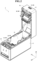
- FIG. 1 and FIG. 2 are each a perspective view for illustrating a printer according to an embodiment.
- a printer 1 is the printer 1 that performs printing on a linerless label having a pressure-sensitive adhesive surface on a back surface thereof.
- the linerless label does not have a liner that covers the pressure-sensitive adhesive surface.
- the linerless label is made of paper, but a material of the linerless label is not limited to paper.
- the linerless label may be made of a resin film.
- the linerless label is simply referred to as a label L.
- the printer 1 includes a casing 10, a printing unit 30, a cutter unit 40, and a sensor 80. The printer 1 is placed on a placement surface.
- a direction perpendicular to the placement surface is referred to as an up-and-down direction (the arrow "UP” indicates an upper side), and two directions orthogonal to the up-and-down direction are referred to as a front-and-rear direction (the arrow "FR” indicates a front side) and a right-and-left direction (the arrow "LH” indicates a left side).
- the casing 10 is formed into a rectangular parallelepiped shape.
- the casing 10 has a divided shape obtained by dividing the casing 10 into an upper part and a lower part, that is, an upper cover 12 and a case main body 11, respectively.
- the case main body 11 forms a lower half part of the casing 10.
- the case main body 11 is formed into a box shape opened upward, and is placed on the placement surface.
- the upper cover 12 forms an upper half part of the casing 10.
- a lower portion of a rear end of the upper cover 12 is pivotably coupled to an upper portion of a rear end of the case main body 11.
- the upper cover 12 is pivoted with respect to the case main body 11 about an axis extending in the right-and-left direction.
- the upper cover 12 is pivoted with respect to the case main body 11, to thereby open and close an opening of the case main body 11.
- the upper cover 12 is formed into a box shape opened downward. When the upper cover 12 is at a closing position, the upper cover 12 is superposed on the case main body 11 from above, and closes the opening of the case main body 11.
- the upper cover 12 When the upper cover 12 is at an opening position, the upper cover 12 retreats from an upper side of the case main body 11, and opens the opening of the case main body 11. Unless otherwise noted, description is made below of the printer 1 under a state in which the upper cover 12 closes the opening of the case main body 11.
- the casing 10 includes a receiving portion 14, a sheet passing portion 16, and a delivery slot 18.
- the receiving portion 14 receives the label L before printing.
- the sheet passing portion 16 allows passage of the label L drawn out from the receiving portion 14. Through the delivery slot 18, the label L printed by the printing unit 30 is delivered to an outside of the casing 10.
- the receiving portion 14 receives the label L wound into a roll shape.
- the receiving portion 14 is formed in the case main body 11 as a recessed portion opened upward, and is closed by the upper cover 12.
- the receiving portion 14 is formed in a rear portion of the casing 10.
- the receiving portion 14 receives the label L having a roll shape under a state in which a winding axis of the label L extends along the right-and-left direction.
- the label L is drawn out from the receiving portion 14 under a state in which a print surface of the label L faces upward and a pressure-sensitive adhesive surface of the label L faces downward.
- the receiving portion 14 is formed so as to be capable of receiving therein a plurality of kinds of labels L having different sheet widths. Irrespective of the sheet width of the received label L, the receiving portion 14 holds the label L such that a center of the label L in a width direction passes a center of the sheet passing portion 16 in the right-and-left direction.
- the delivery slot 18 is defined between a front end of the case main body 11 and a front end of the upper cover 12.
- the delivery slot 18 allows communication between an inside and an outside of the casing 10.
- the delivery slot 18 is formed into a slit shape extending in the right-and-left direction. Through the delivery slot 18, the label L is delivered toward a front side of the printer.
- the sheet passing portion 16 extends to the front side from the receiving portion 14 toward the delivery slot 18. Details of the sheet passing portion 16 are described later.
- a direction of conveying the label L in the sheet passing portion 16 is referred to as a conveying direction.
- a side to which the label L is conveyed is referred to as a downstream side
- a side opposite to the downstream side is referred to as an upstream side.
- the conveying direction substantially matches the front-and-rear direction.
- the width direction of the strip-shaped label L located in the casing 10 matches the right-and-left direction.
- the conveying direction match the front-and-rear direction, and the conveying direction may be oblique to the front-and-rear direction.
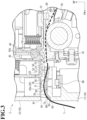
- FIG. 3 is an enlarged sectional view for illustrating the printer according to the embodiment taken along the line III-III of FIG. 1 .
- the printing unit 30 is arranged inside the casing 10.
- the printing unit 30 is arranged between the receiving portion 14 and the delivery slot 18 in the conveying direction.
- the printing unit 30 includes a thermal head 31 and a platen roller 32.
- the thermal head 31 performs printing on the label L.
- the platen roller 32 conveys the label L toward the delivery slot 18 while sandwiching the label L between the platen roller 32 and the thermal head 31.
- the thermal head 31 is arranged in the upper cover 12.
- the thermal head 31 is fixed to a front end portion of the upper cover 12.
- the thermal head 31 includes a plurality of heating elements linearly arrayed along the right-and-left direction. The heating elements are opposed to the print surface of the label L located in the sheet passing portion 16 under a state in which the upper cover 12 closes the opening of the case main body 11.
- the platen roller 32 is a rubber roller extending in the right-and-left direction.
- the platen roller 32 is arranged inside the case main body 11.
- the platen roller 32 is rotatable about the axis extending along the right-and-left direction, and is rotated in accordance with a driving force of a driving motor (not shown) during conveyance of the label L.
- the platen roller 32 and the thermal head 31 are opposed to each other in the up-and-down direction through intermediation of the label L located in the sheet passing portion 16.
- the thermal head 31 is held in close contact with the platen roller 32 through intermediation of the label L.
- the label L is caused to pass between the platen roller 32 and the thermal head 31 along with rotation of the platen roller 32.
- a heating pattern of the heating elements of the thermal head 31 is controlled based on a signal output from a control board (not shown). Transfer of heat from the heating elements to a print surface L1 of the label L allows information (such as characters and figures) associated with the heating pattern to be printed on the print surface L 1.
- the cutter unit 40 is arranged between the printing unit 30 and the delivery slot 18 in the conveying direction.
- the cutter unit 40 is arranged at a distance from the delivery slot 18 in the conveying direction.
- the cutter unit 40 includes a fixed blade 41, a movable blade 42, and a moving mechanism (not shown).
- the cutter unit 40 causes the movable blade 42 to reciprocate with respect to the label L with the moving mechanism (not shown), and sandwiches the label L between the movable blade 42 and the fixed blade 41, to thereby form a cut in the label L.
- the cutter unit 40 leaves an uncut portion La (see FIG. 4 ) at a center portion of the label L in the width direction, that is, performs so-called partial cutting, although this is not essential.
- the fixed blade 41 is arranged in the case main body 11.
- the fixed blade 41 is opposed to the pressure-sensitive adhesive surface of the label L located in the sheet passing portion 16.
- the fixed blade 41 is formed into a plate-like shape extending in the right-and-left direction.
- the fixed blade 41 is fixed to the case main body 11.
- the movable blade 42 is arranged in the upper cover 12.
- the movable blade 42 is opposed to the print surface L1 of the label L located in the sheet passing portion 16.
- the movable blade 42 is formed into a plate-like shape extending in the right-and-left direction. Further, the movable blade 42 is reciprocated by the moving mechanism (not shown) in the up-and-down direction. Along with downward movement, the movable blade 42 is brought close to the fixed blade 41, and a back concave surface 42a of the movable blade 42 facing the upstream side is brought into slide-contact with an upper edge of the fixed blade 41 from the downstream side. The movable blade 42 is moved downward while sandwiching the label L between the movable blade 42 and the fixed blade 41, thereby cutting the label L between the back concave surface 42a and the upper edge of the fixed blade 41.
- FIG. 4 is a perspective view for illustrating the sheet passing portion of the printer according to the embodiment.
- the sheet passing portion 16 includes a guide surface 20 to be opposed to the pressure-sensitive adhesive surface of the label L.
- the guide surface 20 is provided between the cutter unit 40 and the delivery slot 18 in the conveying direction.
- the guide surface 20 is formed on the case main body 11.
- the guide surface 20 extends from a lower portion of an opening edge of the delivery slot 18 to the upstream side.
- the guide surface 20 includes an upstream portion 21, a downstream portion 23, and a midstream portion 22 that are divided in the conveying direction along boundary lines extending in the right-and-left direction.
- the upstream portion 21 includes an upstream-side end portion of the guide surface 20.
- the upstream portion 21 extends from an upstream-side edge of the guide surface 20 towards the delivery slot 18 side.
- the upstream portion 21 extends upward as extending from the rear side toward the front side.
- the upstream portion 21 is a flat surface.
- the upstream portion 21 is provided so as to overlap the fixed blade 41 in the front-and-rear direction.
- the upstream portion 21 and the fixed blade 41 define a gap in the front-and-rear direction therebetween, and the gap allows the movable blade 42 to move downward and enter between the upstream portion 21 and the fixed blade 41.
- the midstream portion 22 is adjacent to the upstream portion 21 on the downstream side.
- the midstream portion 22 extends from a downstream-side edge of the upstream portion 21 towards the delivery slot 18 side.
- the midstream portion 22 extends in parallel to the front-and-rear direction.
- the midstream portion 22 is a flat surface.
- a size of the midstream portion 22 in the front-and-rear direction is larger than a size of the upstream portion 21 in the front-and-rear direction.
- a sensor opening 25 is formed in the midstream portion 22.
- the sensor opening 25 is formed in a center portion 22a of the midstream portion 22 in the right-and-left direction.
- the center portion 22a in the right-and-left direction is, for example, a center region when the midstream portion 22 is equally divided into three regions in the right-and-left direction.
- the sensor opening 25 is formed in a portion of the midstream portion 22 at an equal distance from each end of the midstream portion 22 in the right-and-left direction.
- the sensor opening 25 allows communication between an inside and an outside of the case main body 11 in the up-and-down direction.
- the downstream portion 23 includes a downstream-side end portion of the guide surface 20.
- the downstream portion 23 is adjacent to the midstream portion 22 on the downstream side.
- the downstream portion 23 extends from a downstream-side edge of the midstream portion 22 towards the delivery slot 18 side.
- the downstream portion 23 extends downward as extending from the rear side toward the front side.
- the downstream portion 23 is a flat surface.
- the downstream portion 23 extends at an inclination steeper than that of the upstream portion 21 with respect to the front-and-rear direction.
- a size of the downstream portion 23 in the front-and-rear direction is smaller than the size of the midstream portion 22 in the front-and-rear direction and the size of the upstream portion 21 in the front-and-rear direction.
- Upstream ribs 50, downstream ribs 60, and midstream ribs 70 are formed upright on the guide surface 20.
- the upstream ribs 50, the downstream ribs 60, and the midstream ribs 70 have thicknesses in the right-and-left direction, and extend in the front-and-rear direction.
- the upstream ribs 50 are formed upright on the upstream portion 21.
- a plurality of upstream ribs 50 are formed at intervals in the right-and-left direction.
- the upstream ribs 50 are arranged symmetrically with respect to the center of the guide surface 20 in the right-and-left direction.
- the upstream ribs 50 are formed over an entire region between both right and left ends of the guide surface 20.
- the upstream ribs 50 are formed so as to match each other when seen from the right-and-left direction.
- Each of the upstream ribs 50 includes a rear edge 51, an upper edge 52, and a front edge 53.
- the rear edge 51 extends from an upstream-side edge of the upstream portion 21 towards the downstream side.
- the rear edge 51 extends linearly towards an upper front side of the printer from the upstream-side edge of the upstream portion 21 so as to be distant from the upstream portion 21 as extending toward the downstream side.
- the upper edge 52 extends from a downstream-side end portion of the rear edge 51 t towards o the downstream side.
- the upper edge 52 extends linearly towards the upper front side from the downstream-side end portion of the rear edge 51 in parallel to the upstream portion 21.
- the front edge 53 extends from a downstream-side end portion of the upper edge 52 to towards the downstream side.
- the front edge 53 extends linearly towards a lower front side of the printer from the downstream-side end portion of the upper edge 52 so as to be close to the upstream portion 21 as extending toward the downstream side.
- the upper edge 52 is connected to the downstream-side edge of the upstream portion 21.
- the downstream ribs 60 are formed upright on the downstream portion 23.
- a plurality of downstream ribs 60 are formed at intervals in the right-and-left direction.
- the downstream ribs 60 are arranged symmetrically with respect to the center of the guide surface 20 in the right-and-left direction.
- the downstream ribs 60 are preferably arranged so as to overlap at least some of the upstream ribs 50 in a one-to-one relationship in the front-and-rear direction.
- the number of the downstream ribs 60 is smaller than the number of the upstream ribs 50 by two, and the downstream ribs 60 are arranged so as to overlap, in the one-to-one relationship in the front-and-rear direction, the upstream ribs 50 excluding the upstream ribs 50 located at each end in the right-and-left direction among the plurality of upstream ribs 50. That is, the downstream ribs 60 are formed in a region in the right-and-left direction inside both right and left ends of the guide surface 20. However, similarly to the upstream ribs 50, the downstream ribs 60 may be formed over the entire region between the both right and left ends of the guide surface 20.
- the downstream ribs 60 are formed so as to match each other when seen from the right-and-left direction.
- Each of the downstream ribs 60 includes an upper edge 61 and a front edge 62.
- the upper edge 61 extends from an upstream-side edge of the downstream portion 23 towards the downstream side.
- the upper edge 61 extends linearly towards a front side of the printer from the upstream-side edge of the downstream portion 23 so as to be distant from the downstream portion 23 as extending toward the downstream side.
- the upper edge 61 is formed such that the downstream rib 60 is prevented from protruding more to the upper side than a tangent line of the midstream portion 22 when seen from the right-and-left direction.
- the upper edge 61 extends from the downstream-side edge of the midstream portion 22 in parallel to the midstream portion 22.
- the upper edge 61 may extend from the downstream-side edge of the midstream portion 22 towards the lower front side obliquely to the midstream portion 22 such that the downstream rib 60 is prevented from protruding more to the upper side than the tangent line of the midstream portion 22 when seen from the right-and-left direction.
- the front edge 62 extends from the downstream-side end portion of the upper edge 61 towards the downstream side.
- the front edge 62 extends linearly towards the lower front side from the downstream-side end portion of the upper edge 61 in parallel to the downstream portion 23.
- the front edge 62 is connected to the opening edge of the delivery slot 18.
- the midstream ribs 70 are formed upright on the midstream portion 22.
- a pair of midstream ribs 70 are formed at intervals in the right-and-left direction.
- the midstream ribs 70 are arranged symmetrically with respect to the center of the guide surface 20 in the right-and-left direction. All the midstream ribs 70 are formed only in a region inside both ends in the right-and-left direction of a range in which the upstream ribs 50 are formed, and inside both ends in the right-and-left direction of a range in which the downstream ribs 60 are formed. In this embodiment, all the midstream ribs 70 are formed only in the center portion 22a of the midstream portion 22 in the right-and-left direction.
- the pair of midstream ribs 70 are arranged on both sides in the right-and-left direction across the sensor opening 25.
- An interval between the pair of midstream ribs 70 is equal to or smaller than a double of a width of the sensor opening 25 in the right-and-left direction.
- the interval between the pair of midstream ribs 70 is smaller than a size of the midstream portion 22 in the front-and-rear direction.
- the midstream ribs 70 are respectively connected in a one-to-one relationship to two upstream ribs 50 located closer to the center in the right-and-left direction among the upstream ribs 50, and are respectively connected in a one-to-one relationship to two downstream ribs 60 located closer to the center in the right-and-left direction among the downstream ribs 60.
- the midstream ribs 70 are formed so as to match each other when seen from the right-and-left direction.
- Each of the midstream ribs 70 includes an upper edge 71, a rear edge 72, and a front edge 73.
- the upper edge 71 extends from a position above an upstream-side end portion of the midstream portion 22 to a position above a downstream-side end portion of the midstream portion 22.
- the upper edge 71 extends linearly in parallel to the midstream portion 22.
- the rear edge 72 extends from an upstream-side end portion of the upper edge 71 towards the upstream side, and is connected to the upstream rib 50.
- the rear edge 72 is connected to the downstream-side end portion of the upper edge 52 of the upstream rib 50.
- the rear edge 72 extends in parallel to the upper edge 52 of the upstream rib 50, and is formed so as to extend continuously from the upper edge 52 of the upstream rib 50. With this configuration, the rear edge 72 of the midstream rib 70 is connected to the upper edge 52 of the upstream rib 50 without a level difference when seen from the right-and-left direction.
- the front edge 73 extends from a downstream-side end portion of the upper edge 71 towards the downstream side, and is connected to the downstream rib 60. The front edge 73 is connected to an upstream-side end portion of the front edge 62 of the downstream rib 60.
- the front edge 73 extends in parallel to the front edge 62 of the downstream rib 60, and is formed so as to extend continuously from the front edge 62 of the downstream rib 60. With this configuration, the front edge 73 of the midstream rib 70 is connected to the front edge 62 of the downstream rib 60 without a level difference when seen from the right-and-left direction.
- the sensor 80 is fixed to the case main body 11.
- the sensor 80 detects the label L located between the printing unit 30 and the delivery slot 18 in the sheet passing portion 16.
- the sensor 80 is arranged below the guide surface 20.
- the sensor 80 is arranged at the same position as that of the midstream portion 22 of the guide surface 20 in the conveying direction.
- the sensor 80 detects the label L through the sensor opening 25.
- the sensor 80 detects the center portion of the label L in the width direction.
- the label L is brought into contact with the upstream ribs 50 that are located on the downstream side of the cutter unit 40 and in front of the upper edge of the fixed blade 41.
- the label L hangs down due to gravity outside the delivery slot 18 using the lower portion of the opening edge of the delivery slot 18 as a fulcrum, and thus extends upward inside the delivery slot 18 as extending toward the upstream side.
- the label L is brought into contact with vicinities of the downstream-side end portions of the midstream ribs 70.
- the label L may be brought into contact with the downstream ribs 60.
- the label L Under a state in which the label L thus extends upward inside the delivery slot 18 as extending toward the upstream side, the label L is brought into contact with the upstream ribs 50 and the vicinities of the downstream-side end portions of the midstream ribs 70, thereby exhibiting an upward protruding shape when seen from the right-and-left direction in a space above the midstream portion 22 of the guide surface 20.
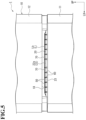
- FIG. 5 is a front view for illustrating a periphery of the delivery slot of the printer according to the embodiment.
- the label L when a leading edge Lb of the label L passes through the space above the midstream portion 22 of the guide surface 20, the label L sometimes hangs down using its contact portion with the upstream ribs 50 as a fulcrum. In this case, the leading edge Lb of the label L is brought into contact with the midstream ribs 70, and thus a leading edge portion of the label L is inhibited from hanging down. Thus, the label L is inhibited from coming into contact with the guide surface 20 (in particular, midstream portion 22).
- the casing 10 includes the guide surface 20 to be opposed to the pressure-sensitive adhesive surface of the label L that has passed through the printing unit 30.
- the guide surface 20 includes: the upstream portion 21, which includes the plurality of upstream ribs 50 formed upright at intervals in the right-and-left direction to extend along the conveying direction; the downstream portion 23, which is provided at a distance from the upstream portion 21 on the downstream side in the conveying direction, and includes the plurality of downstream ribs 60 formed upright at intervals in the right-and-left direction to extend along the conveying direction; and the midstream portion 22, which is provided at the same position as that of the sensor 80 in the conveying direction, is located between the upstream portion 21 and the downstream portion 23, and includes the midstream ribs 70 formed upright only on the center portion 22a in the right-and-left direction.
- the midstream portion 22 of the guide surface 20 is formed to have a large size in the conveying direction. Accordingly, when the label L passes through a position opposed to the midstream portion 22, even though the pressure-sensitive adhesive surface of the label L is liable to stick to the midstream portion 22, the midstream ribs 70 can inhibit the pressure-sensitive adhesive surface of the label L from sticking to the midstream portion 22. Thus, the pressure-sensitive adhesive surface of the label L can be prevented from coming into contact with and sticking to unintended places. Consequently, the printer capable of preventing sticking of the label L inside the delivery slot 18 can be provided.
- the midstream ribs 70 are formed only on the center portion 22a of the midstream portion 22 in the right-and-left direction, and hence can prevent only one side portion of the label L in the right-and-left direction from sticking to the midstream ribs 70 and causing meandering of the label L. Accordingly, a paper jam of the label L can be prevented from occurring inside the delivery slot 18.
- the center portion 22a of the midstream portion 22 is located in the region in the right-and-left direction inside both ends of a range in which the plurality of upstream ribs 50 are formed and inside both ends of a range in which the plurality of downstream ribs 60 are formed.
- the upstream ribs 50 and the downstream ribs 60 are provided in a wider region in the right-and-left direction than the region in which the midstream ribs 70 are provided.
- the label L can be guided along a desired path through a space that the guide surface 20 faces. Accordingly, the pressure-sensitive adhesive surface of the label L can be more reliably prevented from coming into contact with and sticking to unintended places.
- the sensor opening 25 facing the sensor 80 is formed in the midstream portion 22.
- the sensor opening 25 is formed in the midstream portion 22 of the guide surface 20, and hence the midstream portion 22 is formed to have a large size in the conveying direction, thereby being capable of providing an optimum configuration that achieves the actions and effects described above.
- the pair of midstream ribs 70 are arranged on both sides in the right-and-left direction across the sensor 80. With this configuration, the pair of midstream ribs 70 can inhibit the label L from sticking to the midstream portion 22 of the guide surface 20 at a detection position of the sensor 80. Accordingly, the label L is prevented from sticking to the guide surface 20 and being out of the detection position of the sensor 80, thereby being capable of accurately detecting the presence or absence of the label L by the sensor 80.
- the downstream ribs 60 do not protrude from the tangent line of the midstream portion 22 when seen from the right-and-left direction.
- the receiving portion 14 receives the label L wound into a roll shape.
- the label L having a long length passes through the space that the guide surface 20 faces, thereby being capable of providing the printer 1 suitable for attaining the actions and effects described above in order to achieve stable delivery of the label L.
- a pair of midstream ribs 70 are provided.
- only one midstream rib may be provided, or three or more midstream ribs may be provided.
- the midstream rib 70 is connected to the upstream rib 50 and the downstream rib 60, but the midstream rib may be not connected to at least any one of the upstream rib 50 and the downstream rib 60.
- the midstream rib extend such that the edge of the midstream rib extends continuously from the edge of the upstream rib and the edge of the downstream rib when seen from the right-and-left direction.
- the midstream rib may be not connected to the upstream rib.
- the midstream rib and the upstream rib which is arranged to be shifted from the midstream rib in the right-and-left direction, are seen from the right-and-left direction, the midstream rib has the edge extending continuously from the edge of the upstream rib.
- the upstream ribs 50, the midstream ribs 70 and the downstream ribs 60 are all arranged to be symmetrical with respect to the center of the guide surface 20 in the right-and-left direction. However, this is not essential.
Landscapes
- Engineering & Computer Science (AREA)
- Mechanical Engineering (AREA)
- Handling Of Sheets (AREA)
- Handling Of Continuous Sheets Of Paper (AREA)
Abstract
Description
- The present invention relates to a printer.
- Hitherto, there has been known a thermal printer that operates as follows. Under a state in which a recording sheet is sandwiched between a platen roller and a thermal head, the platen roller is rotated, and thus printing is performed by the thermal head on a print surface of the recording sheet while the recording sheet is conveyed. Incidentally, in order to reduce environmental loads and improve convenience, for labels such as POS labels on food and various display labels, a so-called linerless label is used as a recording sheet in some cases. The linerless label is a recording sheet without a liner configured to cover a pressure-sensitive adhesive surface formed opposite to a print surface of the recording sheet.
- In a printer that performs printing on linerless labels, when the printed labels are continuously issued, the labels delivered from the printer may stick to unintended places such as an outer surface of the printer or a periphery of the printer, which may interfere with delivery of the labels. For this reason, some printers are provided with a sensor that detects the presence or absence of the label in a sheet passing portion between a cutting section that cuts the printed labels and a delivery slot, and the printers restrict printing of the labels under a state in which the cut labels are not delivered, thereby regulating continuous issuance of the labels.
- In the printer provided with the sensor that detects the label, a space for arranging the sensor is provided in the sheet passing portion. Thus, the sheet passing portion is provided over a relatively long length inside the delivery slot. However, as the length of the sheet passing portion becomes longer, an inner surface of the sheet passing portion to be opposed to a pressure-sensitive adhesive surface of the label also becomes larger in a direction of conveying the label, and hence the pressure-sensitive adhesive surface of the label is liable to stick to the inner surface of the sheet passing portion. When the label sticks to the inner surface of the sheet passing portion, the label sometimes does not pass through a detection position of the sensor so that the sensor cannot detect the label accurately. Accordingly, it is desired to prevent the pressure-sensitive adhesive surface of the label from sticking to the inner surface of the sheet passing portion. As an example of the related art of this type, there is known a label printer having a configuration in which a non-adhesive sheet is bonded to a surface defining the delivery slot with which the pressure-sensitive adhesive surface of the label is brought into contact (see
Japanese Patent Application Laid-open No. 2001-18940 - However, in the above-mentioned related art, a new component is used to prevent sticking of the pressure-sensitive adhesive surface of the label, and hence manufacturing cost may increase due to an increase in the number of components. Accordingly, there is still room for improvement in preventing sticking of the label inside the delivery slot.
- One of objects of the present disclosure is to provide a printer capable of preventing sticking of a label inside a delivery slot.
- According to one embodiment of the present invention, there is provided a printer configured to perform printing on a linerless label including a pressure-sensitive adhesive surface formed on a back surface of the linerless label. The printer includes: a casing including: a receiving portion configured to receive the linerless label before printing; and a delivery slot through which the printed linerless label is delivered; a printing unit including: a thermal head, which is arranged inside the casing, and is configured to perform printing on the linerless label; and a platen roller, which extends in a width direction of the linerless label, and is configured to convey the linerless label toward the delivery slot while sandwiching the linerless label between the platen roller and the thermal head; and a sensor configured to detect the linerless label located between the printing unit and the delivery slot. The casing includes a guide surface to be opposed to the pressure-sensitive adhesive surface of the linerless label that has passed through the printing unit. The guide surface includes: an upstream portion, which includes a plurality of upstream ribs formed upright at intervals in the width direction to extend along a conveying direction of the linerless label; a downstream portion, which is provided at a distance from the upstream portion on a downstream side in the conveying direction, and includes a plurality of downstream ribs formed upright at intervals in the width direction to extend along the conveying direction; and a midstream portion, which is provided at the same position as that of the sensor in the conveying direction, is located between the upstream portion and the downstream portion, and includes at least one midstream rib formed upright only on a center portion of the midstream portion in the width direction to extend along the conveying direction.
- In the above-mentioned printer according to the one embodiment of the present invention, preferably the center portion is provided in a region in the width direction inside both ends of a range in which the plurality of upstream ribs are formed and inside both ends of a range in which the plurality of downstream ribs are formed.
- In the above-mentioned printer according to the one embodiment of the present invention, preferably an opening is formed in the midstream portion, and wherein the sensor detects the linerless label through the opening.
- In the above-mentioned printer according to the one embodiment of the present invention, preferably the at least one midstream rib includes a pair of midstream ribs arranged on both sides in the width direction across the sensor.
- In the above-mentioned printer according to the one embodiment of the present invention, preferably the downstream ribs are prevented from protruding from a tangent line of the midstream portion when seen from the width direction.
- In the above-mentioned printer according to the one embodiment of the present invention, preferably the receiving portion receives the linerless label wound into a roll shape.
-
-
FIG. 1 is a perspective view for illustrating a printer according to an embodiment. -
FIG. 2 is a perspective view for illustrating the printer according to the embodiment. -
FIG. 3 is an enlarged sectional view for illustrating the printer according to the embodiment taken along the line III-III ofFIG. 1 . -
FIG. 4 is a perspective view for illustrating a sheet passing portion of the printer according to the embodiment. -
FIG. 5 is a front view for illustrating a periphery of a delivery slot of the printer according to the embodiment. - Now, an embodiment of the present invention is described by way of example only based on the drawings. In the following description, components having the same or similar function are denoted by the same reference symbols. In some cases, overlapping description of the components is omitted.
-
FIG. 1 andFIG. 2 are each a perspective view for illustrating a printer according to an embodiment. As illustrated inFIG. 1 , aprinter 1 is theprinter 1 that performs printing on a linerless label having a pressure-sensitive adhesive surface on a back surface thereof. The linerless label does not have a liner that covers the pressure-sensitive adhesive surface. In this embodiment, the linerless label is made of paper, but a material of the linerless label is not limited to paper. For example, the linerless label may be made of a resin film. In the following description, the linerless label is simply referred to as a label L. Theprinter 1 includes acasing 10, aprinting unit 30, acutter unit 40, and asensor 80. Theprinter 1 is placed on a placement surface. In the following description of thecasing 10 and theprinting unit 30, a direction perpendicular to the placement surface is referred to as an up-and-down direction (the arrow "UP" indicates an upper side), and two directions orthogonal to the up-and-down direction are referred to as a front-and-rear direction (the arrow "FR" indicates a front side) and a right-and-left direction (the arrow "LH" indicates a left side). - The
casing 10 is formed into a rectangular parallelepiped shape. Thecasing 10 has a divided shape obtained by dividing thecasing 10 into an upper part and a lower part, that is, anupper cover 12 and a casemain body 11, respectively. The casemain body 11 forms a lower half part of thecasing 10. The casemain body 11 is formed into a box shape opened upward, and is placed on the placement surface. - The
upper cover 12 forms an upper half part of thecasing 10. A lower portion of a rear end of theupper cover 12 is pivotably coupled to an upper portion of a rear end of the casemain body 11. Theupper cover 12 is pivoted with respect to the casemain body 11 about an axis extending in the right-and-left direction. Theupper cover 12 is pivoted with respect to the casemain body 11, to thereby open and close an opening of the casemain body 11. Theupper cover 12 is formed into a box shape opened downward. When theupper cover 12 is at a closing position, theupper cover 12 is superposed on the casemain body 11 from above, and closes the opening of the casemain body 11. When theupper cover 12 is at an opening position, theupper cover 12 retreats from an upper side of the casemain body 11, and opens the opening of the casemain body 11. Unless otherwise noted, description is made below of theprinter 1 under a state in which theupper cover 12 closes the opening of the casemain body 11. - The
casing 10 includes a receivingportion 14, asheet passing portion 16, and adelivery slot 18. Thereceiving portion 14 receives the label L before printing. Thesheet passing portion 16 allows passage of the label L drawn out from thereceiving portion 14. Through thedelivery slot 18, the label L printed by theprinting unit 30 is delivered to an outside of thecasing 10. - The
receiving portion 14 receives the label L wound into a roll shape. The receivingportion 14 is formed in the casemain body 11 as a recessed portion opened upward, and is closed by theupper cover 12. The receivingportion 14 is formed in a rear portion of thecasing 10. The receivingportion 14 receives the label L having a roll shape under a state in which a winding axis of the label L extends along the right-and-left direction. The label L is drawn out from the receivingportion 14 under a state in which a print surface of the label L faces upward and a pressure-sensitive adhesive surface of the label L faces downward. In this embodiment, the receivingportion 14 is formed so as to be capable of receiving therein a plurality of kinds of labels L having different sheet widths. Irrespective of the sheet width of the received label L, the receivingportion 14 holds the label L such that a center of the label L in a width direction passes a center of thesheet passing portion 16 in the right-and-left direction. - The
delivery slot 18 is defined between a front end of the casemain body 11 and a front end of theupper cover 12. Thedelivery slot 18 allows communication between an inside and an outside of thecasing 10. Thedelivery slot 18 is formed into a slit shape extending in the right-and-left direction. Through thedelivery slot 18, the label L is delivered toward a front side of the printer. Thesheet passing portion 16 extends to the front side from the receivingportion 14 toward thedelivery slot 18. Details of thesheet passing portion 16 are described later. - In the following description of the
printer 1, a direction of conveying the label L in thesheet passing portion 16 is referred to as a conveying direction. In the conveying direction, a side to which the label L is conveyed is referred to as a downstream side, and a side opposite to the downstream side is referred to as an upstream side. In this embodiment, the conveying direction substantially matches the front-and-rear direction. Further, the width direction of the strip-shaped label L located in thecasing 10 matches the right-and-left direction. However, it is not always required that the conveying direction match the front-and-rear direction, and the conveying direction may be oblique to the front-and-rear direction. -
FIG. 3 is an enlarged sectional view for illustrating the printer according to the embodiment taken along the line III-III ofFIG. 1 . As illustrated inFIG. 3 , theprinting unit 30 is arranged inside thecasing 10. Theprinting unit 30 is arranged between the receivingportion 14 and thedelivery slot 18 in the conveying direction. Theprinting unit 30 includes athermal head 31 and aplaten roller 32. Thethermal head 31 performs printing on the label L. Theplaten roller 32 conveys the label L toward thedelivery slot 18 while sandwiching the label L between theplaten roller 32 and thethermal head 31. - The
thermal head 31 is arranged in theupper cover 12. Thethermal head 31 is fixed to a front end portion of theupper cover 12. Thethermal head 31 includes a plurality of heating elements linearly arrayed along the right-and-left direction. The heating elements are opposed to the print surface of the label L located in thesheet passing portion 16 under a state in which theupper cover 12 closes the opening of the casemain body 11. - The
platen roller 32 is a rubber roller extending in the right-and-left direction. Theplaten roller 32 is arranged inside the casemain body 11. Theplaten roller 32 is rotatable about the axis extending along the right-and-left direction, and is rotated in accordance with a driving force of a driving motor (not shown) during conveyance of the label L. - The
platen roller 32 and thethermal head 31 are opposed to each other in the up-and-down direction through intermediation of the label L located in thesheet passing portion 16. Thethermal head 31 is held in close contact with theplaten roller 32 through intermediation of the label L. The label L is caused to pass between theplaten roller 32 and thethermal head 31 along with rotation of theplaten roller 32. A heating pattern of the heating elements of thethermal head 31 is controlled based on a signal output from a control board (not shown). Transfer of heat from the heating elements to a print surface L1 of the label L allows information (such as characters and figures) associated with the heating pattern to be printed on theprint surface L 1. - The
cutter unit 40 is arranged between theprinting unit 30 and thedelivery slot 18 in the conveying direction. Thecutter unit 40 is arranged at a distance from thedelivery slot 18 in the conveying direction. Thecutter unit 40 includes a fixedblade 41, amovable blade 42, and a moving mechanism (not shown). Thecutter unit 40 causes themovable blade 42 to reciprocate with respect to the label L with the moving mechanism (not shown), and sandwiches the label L between themovable blade 42 and the fixedblade 41, to thereby form a cut in the label L. Thecutter unit 40 leaves an uncut portion La (seeFIG. 4 ) at a center portion of the label L in the width direction, that is, performs so-called partial cutting, although this is not essential. - The fixed
blade 41 is arranged in the casemain body 11. The fixedblade 41 is opposed to the pressure-sensitive adhesive surface of the label L located in thesheet passing portion 16. The fixedblade 41 is formed into a plate-like shape extending in the right-and-left direction. The fixedblade 41 is fixed to the casemain body 11. - The
movable blade 42 is arranged in theupper cover 12. Themovable blade 42 is opposed to the print surface L1 of the label L located in thesheet passing portion 16. Themovable blade 42 is formed into a plate-like shape extending in the right-and-left direction. Further, themovable blade 42 is reciprocated by the moving mechanism (not shown) in the up-and-down direction. Along with downward movement, themovable blade 42 is brought close to the fixedblade 41, and a backconcave surface 42a of themovable blade 42 facing the upstream side is brought into slide-contact with an upper edge of the fixedblade 41 from the downstream side. Themovable blade 42 is moved downward while sandwiching the label L between themovable blade 42 and the fixedblade 41, thereby cutting the label L between the backconcave surface 42a and the upper edge of the fixedblade 41. - Here, the
sheet passing portion 16 is described.FIG. 4 is a perspective view for illustrating the sheet passing portion of the printer according to the embodiment. As illustrated inFIG. 3 andFIG. 4 , thesheet passing portion 16 includes aguide surface 20 to be opposed to the pressure-sensitive adhesive surface of the label L. Theguide surface 20 is provided between thecutter unit 40 and thedelivery slot 18 in the conveying direction. Theguide surface 20 is formed on the casemain body 11. Theguide surface 20 extends from a lower portion of an opening edge of thedelivery slot 18 to the upstream side. Theguide surface 20 includes anupstream portion 21, adownstream portion 23, and amidstream portion 22 that are divided in the conveying direction along boundary lines extending in the right-and-left direction. - The
upstream portion 21 includes an upstream-side end portion of theguide surface 20. Theupstream portion 21 extends from an upstream-side edge of theguide surface 20 towards thedelivery slot 18 side. Theupstream portion 21 extends upward as extending from the rear side toward the front side. Theupstream portion 21 is a flat surface. Theupstream portion 21 is provided so as to overlap the fixedblade 41 in the front-and-rear direction. Theupstream portion 21 and the fixedblade 41 define a gap in the front-and-rear direction therebetween, and the gap allows themovable blade 42 to move downward and enter between theupstream portion 21 and the fixedblade 41. - The
midstream portion 22 is adjacent to theupstream portion 21 on the downstream side. Themidstream portion 22 extends from a downstream-side edge of theupstream portion 21 towards thedelivery slot 18 side. Themidstream portion 22 extends in parallel to the front-and-rear direction. Themidstream portion 22 is a flat surface. A size of themidstream portion 22 in the front-and-rear direction is larger than a size of theupstream portion 21 in the front-and-rear direction. Asensor opening 25 is formed in themidstream portion 22. Thesensor opening 25 is formed in acenter portion 22a of themidstream portion 22 in the right-and-left direction. Thecenter portion 22a in the right-and-left direction is, for example, a center region when themidstream portion 22 is equally divided into three regions in the right-and-left direction. In this embodiment, thesensor opening 25 is formed in a portion of themidstream portion 22 at an equal distance from each end of themidstream portion 22 in the right-and-left direction. Thesensor opening 25 allows communication between an inside and an outside of the casemain body 11 in the up-and-down direction. - The
downstream portion 23 includes a downstream-side end portion of theguide surface 20. Thedownstream portion 23 is adjacent to themidstream portion 22 on the downstream side. Thedownstream portion 23 extends from a downstream-side edge of themidstream portion 22 towards thedelivery slot 18 side. Thedownstream portion 23 extends downward as extending from the rear side toward the front side. Thedownstream portion 23 is a flat surface. Thedownstream portion 23 extends at an inclination steeper than that of theupstream portion 21 with respect to the front-and-rear direction. A size of thedownstream portion 23 in the front-and-rear direction is smaller than the size of themidstream portion 22 in the front-and-rear direction and the size of theupstream portion 21 in the front-and-rear direction. -
Upstream ribs 50,downstream ribs 60, andmidstream ribs 70 are formed upright on theguide surface 20. Theupstream ribs 50, thedownstream ribs 60, and themidstream ribs 70 have thicknesses in the right-and-left direction, and extend in the front-and-rear direction. - The
upstream ribs 50 are formed upright on theupstream portion 21. A plurality ofupstream ribs 50 are formed at intervals in the right-and-left direction. Theupstream ribs 50 are arranged symmetrically with respect to the center of theguide surface 20 in the right-and-left direction. Theupstream ribs 50 are formed over an entire region between both right and left ends of theguide surface 20. - The
upstream ribs 50 are formed so as to match each other when seen from the right-and-left direction. Each of theupstream ribs 50 includes arear edge 51, anupper edge 52, and afront edge 53. Therear edge 51 extends from an upstream-side edge of theupstream portion 21 towards the downstream side. Therear edge 51 extends linearly towards an upper front side of the printer from the upstream-side edge of theupstream portion 21 so as to be distant from theupstream portion 21 as extending toward the downstream side. Theupper edge 52 extends from a downstream-side end portion of the rear edge 51 t towards o the downstream side. Theupper edge 52 extends linearly towards the upper front side from the downstream-side end portion of therear edge 51 in parallel to theupstream portion 21. Thefront edge 53 extends from a downstream-side end portion of theupper edge 52 to towards the downstream side. Thefront edge 53 extends linearly towards a lower front side of the printer from the downstream-side end portion of theupper edge 52 so as to be close to theupstream portion 21 as extending toward the downstream side. Theupper edge 52 is connected to the downstream-side edge of theupstream portion 21. - The
downstream ribs 60 are formed upright on thedownstream portion 23. A plurality ofdownstream ribs 60 are formed at intervals in the right-and-left direction. Thedownstream ribs 60 are arranged symmetrically with respect to the center of theguide surface 20 in the right-and-left direction. Thedownstream ribs 60 are preferably arranged so as to overlap at least some of theupstream ribs 50 in a one-to-one relationship in the front-and-rear direction. In this embodiment, the number of thedownstream ribs 60 is smaller than the number of theupstream ribs 50 by two, and thedownstream ribs 60 are arranged so as to overlap, in the one-to-one relationship in the front-and-rear direction, theupstream ribs 50 excluding theupstream ribs 50 located at each end in the right-and-left direction among the plurality ofupstream ribs 50. That is, thedownstream ribs 60 are formed in a region in the right-and-left direction inside both right and left ends of theguide surface 20. However, similarly to theupstream ribs 50, thedownstream ribs 60 may be formed over the entire region between the both right and left ends of theguide surface 20. - The
downstream ribs 60 are formed so as to match each other when seen from the right-and-left direction. Each of thedownstream ribs 60 includes anupper edge 61 and afront edge 62. Theupper edge 61 extends from an upstream-side edge of thedownstream portion 23 towards the downstream side. Theupper edge 61 extends linearly towards a front side of the printer from the upstream-side edge of thedownstream portion 23 so as to be distant from thedownstream portion 23 as extending toward the downstream side. Theupper edge 61 is formed such that thedownstream rib 60 is prevented from protruding more to the upper side than a tangent line of themidstream portion 22 when seen from the right-and-left direction. In this embodiment, theupper edge 61 extends from the downstream-side edge of themidstream portion 22 in parallel to themidstream portion 22. However, theupper edge 61 may extend from the downstream-side edge of themidstream portion 22 towards the lower front side obliquely to themidstream portion 22 such that thedownstream rib 60 is prevented from protruding more to the upper side than the tangent line of themidstream portion 22 when seen from the right-and-left direction. Thefront edge 62 extends from the downstream-side end portion of theupper edge 61 towards the downstream side. Thefront edge 62 extends linearly towards the lower front side from the downstream-side end portion of theupper edge 61 in parallel to thedownstream portion 23. Thefront edge 62 is connected to the opening edge of thedelivery slot 18. - The
midstream ribs 70 are formed upright on themidstream portion 22. A pair ofmidstream ribs 70 are formed at intervals in the right-and-left direction. Themidstream ribs 70 are arranged symmetrically with respect to the center of theguide surface 20 in the right-and-left direction. All themidstream ribs 70 are formed only in a region inside both ends in the right-and-left direction of a range in which theupstream ribs 50 are formed, and inside both ends in the right-and-left direction of a range in which thedownstream ribs 60 are formed. In this embodiment, all themidstream ribs 70 are formed only in thecenter portion 22a of themidstream portion 22 in the right-and-left direction. The pair ofmidstream ribs 70 are arranged on both sides in the right-and-left direction across thesensor opening 25. An interval between the pair ofmidstream ribs 70 is equal to or smaller than a double of a width of thesensor opening 25 in the right-and-left direction. The interval between the pair ofmidstream ribs 70 is smaller than a size of themidstream portion 22 in the front-and-rear direction. Themidstream ribs 70 are respectively connected in a one-to-one relationship to twoupstream ribs 50 located closer to the center in the right-and-left direction among theupstream ribs 50, and are respectively connected in a one-to-one relationship to twodownstream ribs 60 located closer to the center in the right-and-left direction among thedownstream ribs 60. - The
midstream ribs 70 are formed so as to match each other when seen from the right-and-left direction. Each of themidstream ribs 70 includes anupper edge 71, arear edge 72, and afront edge 73. Theupper edge 71 extends from a position above an upstream-side end portion of themidstream portion 22 to a position above a downstream-side end portion of themidstream portion 22. Theupper edge 71 extends linearly in parallel to themidstream portion 22. Therear edge 72 extends from an upstream-side end portion of theupper edge 71 towards the upstream side, and is connected to theupstream rib 50. Therear edge 72 is connected to the downstream-side end portion of theupper edge 52 of theupstream rib 50. Therear edge 72 extends in parallel to theupper edge 52 of theupstream rib 50, and is formed so as to extend continuously from theupper edge 52 of theupstream rib 50. With this configuration, therear edge 72 of themidstream rib 70 is connected to theupper edge 52 of theupstream rib 50 without a level difference when seen from the right-and-left direction. Thefront edge 73 extends from a downstream-side end portion of theupper edge 71 towards the downstream side, and is connected to thedownstream rib 60. Thefront edge 73 is connected to an upstream-side end portion of thefront edge 62 of thedownstream rib 60. Thefront edge 73 extends in parallel to thefront edge 62 of thedownstream rib 60, and is formed so as to extend continuously from thefront edge 62 of thedownstream rib 60. With this configuration, thefront edge 73 of themidstream rib 70 is connected to thefront edge 62 of thedownstream rib 60 without a level difference when seen from the right-and-left direction. - The
sensor 80 is fixed to the casemain body 11. Thesensor 80 detects the label L located between theprinting unit 30 and thedelivery slot 18 in thesheet passing portion 16. Thesensor 80 is arranged below theguide surface 20. Thesensor 80 is arranged at the same position as that of themidstream portion 22 of theguide surface 20 in the conveying direction. Thesensor 80 detects the label L through thesensor opening 25. Thesensor 80 detects the center portion of the label L in the width direction. - As illustrated in
FIG. 3 , the label L is brought into contact with theupstream ribs 50 that are located on the downstream side of thecutter unit 40 and in front of the upper edge of the fixedblade 41. The label L hangs down due to gravity outside thedelivery slot 18 using the lower portion of the opening edge of thedelivery slot 18 as a fulcrum, and thus extends upward inside thedelivery slot 18 as extending toward the upstream side. Inside thedelivery slot 18, the label L is brought into contact with vicinities of the downstream-side end portions of themidstream ribs 70. Inside thedelivery slot 18, the label L may be brought into contact with thedownstream ribs 60. Under a state in which the label L thus extends upward inside thedelivery slot 18 as extending toward the upstream side, the label L is brought into contact with theupstream ribs 50 and the vicinities of the downstream-side end portions of themidstream ribs 70, thereby exhibiting an upward protruding shape when seen from the right-and-left direction in a space above themidstream portion 22 of theguide surface 20. -
FIG. 5 is a front view for illustrating a periphery of the delivery slot of the printer according to the embodiment. As illustrated inFIG. 5 , when a leading edge Lb of the label L passes through the space above themidstream portion 22 of theguide surface 20, the label L sometimes hangs down using its contact portion with theupstream ribs 50 as a fulcrum. In this case, the leading edge Lb of the label L is brought into contact with themidstream ribs 70, and thus a leading edge portion of the label L is inhibited from hanging down. Thus, the label L is inhibited from coming into contact with the guide surface 20 (in particular, midstream portion 22). - As described above, in this embodiment, the
casing 10 includes theguide surface 20 to be opposed to the pressure-sensitive adhesive surface of the label L that has passed through theprinting unit 30. Theguide surface 20 includes: theupstream portion 21, which includes the plurality ofupstream ribs 50 formed upright at intervals in the right-and-left direction to extend along the conveying direction; thedownstream portion 23, which is provided at a distance from theupstream portion 21 on the downstream side in the conveying direction, and includes the plurality ofdownstream ribs 60 formed upright at intervals in the right-and-left direction to extend along the conveying direction; and themidstream portion 22, which is provided at the same position as that of thesensor 80 in the conveying direction, is located between theupstream portion 21 and thedownstream portion 23, and includes themidstream ribs 70 formed upright only on thecenter portion 22a in the right-and-left direction. - With this configuration, in order to ensure a space for arranging the
sensor 80, themidstream portion 22 of theguide surface 20 is formed to have a large size in the conveying direction. Accordingly, when the label L passes through a position opposed to themidstream portion 22, even though the pressure-sensitive adhesive surface of the label L is liable to stick to themidstream portion 22, themidstream ribs 70 can inhibit the pressure-sensitive adhesive surface of the label L from sticking to themidstream portion 22. Thus, the pressure-sensitive adhesive surface of the label L can be prevented from coming into contact with and sticking to unintended places. Consequently, the printer capable of preventing sticking of the label L inside thedelivery slot 18 can be provided. - In addition, the
midstream ribs 70 are formed only on thecenter portion 22a of themidstream portion 22 in the right-and-left direction, and hence can prevent only one side portion of the label L in the right-and-left direction from sticking to themidstream ribs 70 and causing meandering of the label L. Accordingly, a paper jam of the label L can be prevented from occurring inside thedelivery slot 18. - The
center portion 22a of themidstream portion 22 is located in the region in the right-and-left direction inside both ends of a range in which the plurality ofupstream ribs 50 are formed and inside both ends of a range in which the plurality ofdownstream ribs 60 are formed. With this configuration, on both sides in the conveying direction across themidstream portion 22, theupstream ribs 50 and thedownstream ribs 60 are provided in a wider region in the right-and-left direction than the region in which themidstream ribs 70 are provided. Thus, even when themidstream ribs 70 are not provided in the right-and-left direction over a range equivalent to or wider than the range in which theupstream ribs 50 and thedownstream ribs 60 are provided, the label L can be guided along a desired path through a space that theguide surface 20 faces. Accordingly, the pressure-sensitive adhesive surface of the label L can be more reliably prevented from coming into contact with and sticking to unintended places. - The
sensor opening 25 facing thesensor 80 is formed in themidstream portion 22. With this configuration, thesensor opening 25 is formed in themidstream portion 22 of theguide surface 20, and hence themidstream portion 22 is formed to have a large size in the conveying direction, thereby being capable of providing an optimum configuration that achieves the actions and effects described above. - The pair of
midstream ribs 70 are arranged on both sides in the right-and-left direction across thesensor 80. With this configuration, the pair ofmidstream ribs 70 can inhibit the label L from sticking to themidstream portion 22 of theguide surface 20 at a detection position of thesensor 80. Accordingly, the label L is prevented from sticking to theguide surface 20 and being out of the detection position of thesensor 80, thereby being capable of accurately detecting the presence or absence of the label L by thesensor 80. - The
downstream ribs 60 do not protrude from the tangent line of themidstream portion 22 when seen from the right-and-left direction. With this configuration, even when the leading edge of the label L is brought into slide-contact with a region of themidstream portion 22 of theguide surface 20 in the right-and-left direction in which nomidstream rib 70 is provided, the leading edge of the label L can be prevented from being caught on thedownstream ribs 60. Thus, the pressure-sensitive adhesive surface of the label L can be prevented from coming into contact with and sticking to unintended places. - The receiving
portion 14 receives the label L wound into a roll shape. With this configuration, the label L having a long length passes through the space that theguide surface 20 faces, thereby being capable of providing theprinter 1 suitable for attaining the actions and effects described above in order to achieve stable delivery of the label L. - The present invention is not limited to the embodiment described above with reference to the drawings, and various modifications may be made thereto within the technical scope of the present invention as defined by the appended claims. For example, in the embodiment described above, a pair of
midstream ribs 70 are provided. However, only one midstream rib may be provided, or three or more midstream ribs may be provided. - In the embodiment described above, the
midstream rib 70 is connected to theupstream rib 50 and thedownstream rib 60, but the midstream rib may be not connected to at least any one of theupstream rib 50 and thedownstream rib 60. However, it is preferred that the midstream rib extend such that the edge of the midstream rib extends continuously from the edge of the upstream rib and the edge of the downstream rib when seen from the right-and-left direction. For example, the midstream rib may be not connected to the upstream rib. In that case, it is preferred that, when the midstream rib and the upstream rib, which is arranged to be shifted from the midstream rib in the right-and-left direction, are seen from the right-and-left direction, the midstream rib has the edge extending continuously from the edge of the upstream rib. Thus, after the leading edge of the label is brought into slide-contact with and moved onto the edges of the plurality of upstream ribs, the leading edge of the label can be smoothly moved onto the edges of the midstream ribs, thereby being capable of preventing the label from being caught on the midstream ribs. The same holds true for a configuration in which the midstream rib is not connected to the downstream rib. - In the embodiment described above, the
upstream ribs 50, themidstream ribs 70 and thedownstream ribs 60 are all arranged to be symmetrical with respect to the center of theguide surface 20 in the right-and-left direction. However, this is not essential. - Besides the above, the components in the above-mentioned embodiment may be replaced by well-known components as appropriate without departing from the scope of the present invention as defined by the appended claims.
Claims (6)
- A printer (1) configured to perform printing on a linerless label (L) including a pressure-sensitive adhesive surface formed on a back surface of the linerless label (L), the printer (1) comprising:a casing (10) including:a receiving portion (14) configured to receive the linerless label (L) before printing; anda delivery slot (18) through which the printed linerless label (L) is delivered;a printing unit (30) including:a thermal head (31), which is arranged inside the casing (10), and is configured to perform printing on the linerless label (L); anda platen roller (32), which extends in a width direction of the linerless label (L), and is configured to convey the linerless label (L) toward the delivery slot (18) while sandwiching the linerless label (L) between the platen roller (32) and the thermal head (31); anda sensor (80) configured to detect the linerless label (L) located between the printing unit (30) and the delivery slot (18),wherein the casing (10) includes a guide surface (20) to be opposed to the pressure-sensitive adhesive surface of the linerless label (L) that has passed through the printing unit (30),wherein the guide surface (20) includes:an upstream portion (21), which includes a plurality of upstream ribs (50) formed upright at intervals in the width direction to extend along a conveying direction of the linerless label (L);a downstream portion (23), which is provided at a distance from the upstream portion (21) on a downstream side in the conveying direction, and includes a plurality of downstream ribs (60) formed upright at intervals in the width direction to extend along the conveying direction; anda midstream portion (22), which is provided at the same position as that of the sensor (80) in the conveying direction, is located between the upstream portion (21) and the downstream portion (23), and includes at least one midstream rib (70) formed upright only on a center portion (22a) of the midstream portion (22) in the width direction to extend along the conveying direction.
- The printer (1) according to claim 1, wherein the center portion (22a) is provided in a region in the width direction inside both ends of a range in which the plurality of upstream ribs (50) are formed and inside both ends of a range in which the plurality of downstream ribs (60) are formed.
- The printer (1) according to claim 1 or 2,wherein an opening (25) is formed in the midstream portion (22), andwherein the sensor (80) detects the linerless label (L) through the opening (25).
- The printer (1) according to any one of the preceding claims, wherein the at least one midstream rib (70) includes a pair of midstream ribs (70) arranged on both sides in the width direction across the sensor (80).
- The printer (1) according to any one of the preceding claims, wherein the downstream ribs (60) are prevented from protruding above a tangent line of the midstream portion (22) when seen from the width direction.
- The printer (1) according to any one of the preceding claims, wherein the receiving portion (14) receives the linerless label (L) wound into a roll shape.
Applications Claiming Priority (1)
| Application Number | Priority Date | Filing Date | Title |
|---|---|---|---|
| JP2023044855A JP2024134588A (en) | 2023-03-22 | 2023-03-22 | Printer |
Publications (2)
| Publication Number | Publication Date |
|---|---|
| EP4434756A1 true EP4434756A1 (en) | 2024-09-25 |
| EP4434756B1 EP4434756B1 (en) | 2025-12-17 |
Family
ID=90417573
Family Applications (1)
| Application Number | Title | Priority Date | Filing Date |
|---|---|---|---|
| EP24165114.0A Active EP4434756B1 (en) | 2023-03-22 | 2024-03-21 | Printer |
Country Status (4)
| Country | Link |
|---|---|
| US (1) | US12533891B2 (en) |
| EP (1) | EP4434756B1 (en) |
| JP (1) | JP2024134588A (en) |
| CN (2) | CN118683197A (en) |
Citations (2)
| Publication number | Priority date | Publication date | Assignee | Title |
|---|---|---|---|---|
| JP2001018940A (en) | 1999-07-05 | 2001-01-23 | Matsushita Electric Ind Co Ltd | Label printer |
| US20130138391A1 (en) * | 2011-11-30 | 2013-05-30 | Zih Corp. | Platen wrap detection |
Family Cites Families (3)
| Publication number | Priority date | Publication date | Assignee | Title |
|---|---|---|---|---|
| JP5979439B2 (en) * | 2012-11-29 | 2016-08-24 | ブラザー工業株式会社 | Printing device |
| JP5852715B1 (en) * | 2014-08-18 | 2016-02-03 | サトーホールディングス株式会社 | Printer |
| JP7817528B2 (en) * | 2021-12-24 | 2026-02-19 | スター精密株式会社 | printer |
-
2023
- 2023-03-22 JP JP2023044855A patent/JP2024134588A/en active Pending
-
2024
- 2024-03-19 US US18/609,841 patent/US12533891B2/en active Active
- 2024-03-21 EP EP24165114.0A patent/EP4434756B1/en active Active
- 2024-03-22 CN CN202410334044.1A patent/CN118683197A/en active Pending
- 2024-03-22 CN CN202420566433.2U patent/CN221913771U/en active Active
Patent Citations (2)
| Publication number | Priority date | Publication date | Assignee | Title |
|---|---|---|---|---|
| JP2001018940A (en) | 1999-07-05 | 2001-01-23 | Matsushita Electric Ind Co Ltd | Label printer |
| US20130138391A1 (en) * | 2011-11-30 | 2013-05-30 | Zih Corp. | Platen wrap detection |
Also Published As
| Publication number | Publication date |
|---|---|
| EP4434756B1 (en) | 2025-12-17 |
| CN118683197A (en) | 2024-09-24 |
| US20240316951A1 (en) | 2024-09-26 |
| US12533891B2 (en) | 2026-01-27 |
| JP2024134588A (en) | 2024-10-04 |
| CN221913771U (en) | 2024-10-29 |
Similar Documents
| Publication | Publication Date | Title |
|---|---|---|
| CN116080284B (en) | printer | |
| CN102371782B (en) | Printer | |
| CN103832096B (en) | Single vote distribution device and single vote distributing method | |
| US8911166B2 (en) | Cutting device and printer with a cutting device | |
| US5800076A (en) | Printer having guide plate extending to printhead | |
| EP2292541B1 (en) | Cutting apparatus | |
| JP2002144655A (en) | Printer | |
| US8382275B2 (en) | Printer | |
| EP1637333A2 (en) | Printer with thermal activation device and printing method | |
| US11186459B2 (en) | Medium cutting device and image formation apparatus | |
| US7410315B2 (en) | Paper discharge mechanism for a printer, and a printer | |
| EP4434756B1 (en) | Printer | |
| US20030172792A1 (en) | Paper cutter and thermal printer | |
| JP5490762B2 (en) | Thermal printer | |
| JP6676755B2 (en) | Thermal printer and printing method in thermal printer | |
| US5961233A (en) | Continuous paper cutting device for a thermal printer | |
| EP3170671B1 (en) | Printing mechanism and thermal printer | |
| JP2003312070A (en) | Label printer | |
| JP5009997B2 (en) | Tape-shaped recording medium feeding guide and printer having the same | |
| JP7540456B2 (en) | Printing device | |
| US9902176B2 (en) | Printer | |
| JP7738887B2 (en) | Linerless labels and label cutting equipment | |
| JP4522239B2 (en) | Label feeding device | |
| US20240326481A1 (en) | Printer apparatus | |
| JP5534884B2 (en) | Stacker |
Legal Events
| Date | Code | Title | Description |
|---|---|---|---|
| PUAI | Public reference made under article 153(3) epc to a published international application that has entered the european phase |
Free format text: ORIGINAL CODE: 0009012 |
|
| STAA | Information on the status of an ep patent application or granted ep patent |
Free format text: STATUS: THE APPLICATION HAS BEEN PUBLISHED |
|
| AK | Designated contracting states |
Kind code of ref document: A1 Designated state(s): AL AT BE BG CH CY CZ DE DK EE ES FI FR GB GR HR HU IE IS IT LI LT LU LV MC ME MK MT NL NO PL PT RO RS SE SI SK SM TR |
|
| STAA | Information on the status of an ep patent application or granted ep patent |
Free format text: STATUS: REQUEST FOR EXAMINATION WAS MADE |
|
| 17P | Request for examination filed |
Effective date: 20250313 |
|
| GRAP | Despatch of communication of intention to grant a patent |
Free format text: ORIGINAL CODE: EPIDOSNIGR1 |
|
| STAA | Information on the status of an ep patent application or granted ep patent |
Free format text: STATUS: GRANT OF PATENT IS INTENDED |
|
| INTG | Intention to grant announced |
Effective date: 20250722 |
|
| GRAS | Grant fee paid |
Free format text: ORIGINAL CODE: EPIDOSNIGR3 |
|
| GRAA | (expected) grant |
Free format text: ORIGINAL CODE: 0009210 |
|
| STAA | Information on the status of an ep patent application or granted ep patent |
Free format text: STATUS: THE PATENT HAS BEEN GRANTED |
|
| P01 | Opt-out of the competence of the unified patent court (upc) registered |
Free format text: CASE NUMBER: UPC_APP_0010473_4434756/2025 Effective date: 20251021 |
|
| AK | Designated contracting states |
Kind code of ref document: B1 Designated state(s): AL AT BE BG CH CY CZ DE DK EE ES FI FR GB GR HR HU IE IS IT LI LT LU LV MC ME MK MT NL NO PL PT RO RS SE SI SK SM TR |
|
| REG | Reference to a national code |
Ref country code: CH Ref legal event code: F10 Free format text: ST27 STATUS EVENT CODE: U-0-0-F10-F00 (AS PROVIDED BY THE NATIONAL OFFICE) Effective date: 20251217 Ref country code: GB Ref legal event code: FG4D |
|
| REG | Reference to a national code |
Ref country code: DE Ref legal event code: R096 Ref document number: 602024001684 Country of ref document: DE |
|
| REG | Reference to a national code |
Ref country code: LT Ref legal event code: MG9D |
|
| PG25 | Lapsed in a contracting state [announced via postgrant information from national office to epo] |
Ref country code: NO Free format text: LAPSE BECAUSE OF FAILURE TO SUBMIT A TRANSLATION OF THE DESCRIPTION OR TO PAY THE FEE WITHIN THE PRESCRIBED TIME-LIMIT Effective date: 20260317 |
|
| PGFP | Annual fee paid to national office [announced via postgrant information from national office to epo] |
Ref country code: DE Payment date: 20260128 Year of fee payment: 3 |
|
| PG25 | Lapsed in a contracting state [announced via postgrant information from national office to epo] |
Ref country code: FI Free format text: LAPSE BECAUSE OF FAILURE TO SUBMIT A TRANSLATION OF THE DESCRIPTION OR TO PAY THE FEE WITHIN THE PRESCRIBED TIME-LIMIT Effective date: 20251217 Ref country code: HR Free format text: LAPSE BECAUSE OF FAILURE TO SUBMIT A TRANSLATION OF THE DESCRIPTION OR TO PAY THE FEE WITHIN THE PRESCRIBED TIME-LIMIT Effective date: 20251217 |
|
| PGFP | Annual fee paid to national office [announced via postgrant information from national office to epo] |
Ref country code: AT Payment date: 20260301 Year of fee payment: 3 |
|
| PG25 | Lapsed in a contracting state [announced via postgrant information from national office to epo] |
Ref country code: RS Free format text: LAPSE BECAUSE OF FAILURE TO SUBMIT A TRANSLATION OF THE DESCRIPTION OR TO PAY THE FEE WITHIN THE PRESCRIBED TIME-LIMIT Effective date: 20260317 |
|
| PGFP | Annual fee paid to national office [announced via postgrant information from national office to epo] |
Ref country code: FR Payment date: 20260209 Year of fee payment: 3 |
|
| REG | Reference to a national code |
Ref country code: NL Ref legal event code: MP Effective date: 20251217 |
|
| PG25 | Lapsed in a contracting state [announced via postgrant information from national office to epo] |
Ref country code: LV Free format text: LAPSE BECAUSE OF FAILURE TO SUBMIT A TRANSLATION OF THE DESCRIPTION OR TO PAY THE FEE WITHIN THE PRESCRIBED TIME-LIMIT Effective date: 20251217 |
|
| PG25 | Lapsed in a contracting state [announced via postgrant information from national office to epo] |
Ref country code: BG Free format text: LAPSE BECAUSE OF FAILURE TO SUBMIT A TRANSLATION OF THE DESCRIPTION OR TO PAY THE FEE WITHIN THE PRESCRIBED TIME-LIMIT Effective date: 20251217 |
|
| REG | Reference to a national code |
Ref country code: AT Ref legal event code: MK05 Ref document number: 1868169 Country of ref document: AT Kind code of ref document: T Effective date: 20251217 |
|
| PG25 | Lapsed in a contracting state [announced via postgrant information from national office to epo] |
Ref country code: NL Free format text: LAPSE BECAUSE OF FAILURE TO SUBMIT A TRANSLATION OF THE DESCRIPTION OR TO PAY THE FEE WITHIN THE PRESCRIBED TIME-LIMIT Effective date: 20251217 |
|
| PG25 | Lapsed in a contracting state [announced via postgrant information from national office to epo] |
Ref country code: LT Free format text: LAPSE BECAUSE OF FAILURE TO SUBMIT A TRANSLATION OF THE DESCRIPTION OR TO PAY THE FEE WITHIN THE PRESCRIBED TIME-LIMIT Effective date: 20251217 |
|
| PG25 | Lapsed in a contracting state [announced via postgrant information from national office to epo] |
Ref country code: SM Free format text: LAPSE BECAUSE OF FAILURE TO SUBMIT A TRANSLATION OF THE DESCRIPTION OR TO PAY THE FEE WITHIN THE PRESCRIBED TIME-LIMIT Effective date: 20251217 |
|
| PG25 | Lapsed in a contracting state [announced via postgrant information from national office to epo] |
Ref country code: ES Free format text: LAPSE BECAUSE OF FAILURE TO SUBMIT A TRANSLATION OF THE DESCRIPTION OR TO PAY THE FEE WITHIN THE PRESCRIBED TIME-LIMIT Effective date: 20251217 |
|
| PG25 | Lapsed in a contracting state [announced via postgrant information from national office to epo] |
Ref country code: PL Free format text: LAPSE BECAUSE OF FAILURE TO SUBMIT A TRANSLATION OF THE DESCRIPTION OR TO PAY THE FEE WITHIN THE PRESCRIBED TIME-LIMIT Effective date: 20251217 |
|
| PG25 | Lapsed in a contracting state [announced via postgrant information from national office to epo] |
Ref country code: IT Free format text: LAPSE BECAUSE OF FAILURE TO SUBMIT A TRANSLATION OF THE DESCRIPTION OR TO PAY THE FEE WITHIN THE PRESCRIBED TIME-LIMIT Effective date: 20251217 |
|
| PG25 | Lapsed in a contracting state [announced via postgrant information from national office to epo] |
Ref country code: AT Free format text: LAPSE BECAUSE OF FAILURE TO SUBMIT A TRANSLATION OF THE DESCRIPTION OR TO PAY THE FEE WITHIN THE PRESCRIBED TIME-LIMIT Effective date: 20251217 |
|
| PG25 | Lapsed in a contracting state [announced via postgrant information from national office to epo] |
Ref country code: EE Free format text: LAPSE BECAUSE OF FAILURE TO SUBMIT A TRANSLATION OF THE DESCRIPTION OR TO PAY THE FEE WITHIN THE PRESCRIBED TIME-LIMIT Effective date: 20251217 |
|
| PG25 | Lapsed in a contracting state [announced via postgrant information from national office to epo] |
Ref country code: PT Free format text: LAPSE BECAUSE OF FAILURE TO SUBMIT A TRANSLATION OF THE DESCRIPTION OR TO PAY THE FEE WITHIN THE PRESCRIBED TIME-LIMIT Effective date: 20260417 Ref country code: IS Free format text: LAPSE BECAUSE OF FAILURE TO SUBMIT A TRANSLATION OF THE DESCRIPTION OR TO PAY THE FEE WITHIN THE PRESCRIBED TIME-LIMIT Effective date: 20260417 |
|
| PG25 | Lapsed in a contracting state [announced via postgrant information from national office to epo] |
Ref country code: CZ Free format text: LAPSE BECAUSE OF FAILURE TO SUBMIT A TRANSLATION OF THE DESCRIPTION OR TO PAY THE FEE WITHIN THE PRESCRIBED TIME-LIMIT Effective date: 20251217 |
|
| PG25 | Lapsed in a contracting state [announced via postgrant information from national office to epo] |
Ref country code: SK Free format text: LAPSE BECAUSE OF FAILURE TO SUBMIT A TRANSLATION OF THE DESCRIPTION OR TO PAY THE FEE WITHIN THE PRESCRIBED TIME-LIMIT Effective date: 20251217 |
|
| PG25 | Lapsed in a contracting state [announced via postgrant information from national office to epo] |
Ref country code: SE Free format text: LAPSE BECAUSE OF FAILURE TO SUBMIT A TRANSLATION OF THE DESCRIPTION OR TO PAY THE FEE WITHIN THE PRESCRIBED TIME-LIMIT Effective date: 20251217 |