EP4434713A1 - Vehicle interior panel with non-uniform hardness - Google Patents
Vehicle interior panel with non-uniform hardness Download PDFInfo
- Publication number
- EP4434713A1 EP4434713A1 EP24165120.7A EP24165120A EP4434713A1 EP 4434713 A1 EP4434713 A1 EP 4434713A1 EP 24165120 A EP24165120 A EP 24165120A EP 4434713 A1 EP4434713 A1 EP 4434713A1
- Authority
- EP
- European Patent Office
- Prior art keywords
- substrate
- panel
- mat
- thickness
- decorative layer
- Prior art date
- Legal status (The legal status is an assumption and is not a legal conclusion. Google has not performed a legal analysis and makes no representation as to the accuracy of the status listed.)
- Pending
Links
Images

Classifications
-
- B—PERFORMING OPERATIONS; TRANSPORTING
- B29—WORKING OF PLASTICS; WORKING OF SUBSTANCES IN A PLASTIC STATE IN GENERAL
- B29C—SHAPING OR JOINING OF PLASTICS; SHAPING OF MATERIAL IN A PLASTIC STATE, NOT OTHERWISE PROVIDED FOR; AFTER-TREATMENT OF THE SHAPED PRODUCTS, e.g. REPAIRING
- B29C43/00—Compression moulding, i.e. applying external pressure to flow the moulding material; Apparatus therefor
- B29C43/32—Component parts, details or accessories; Auxiliary operations
- B29C43/52—Heating or cooling
-
- B—PERFORMING OPERATIONS; TRANSPORTING
- B29—WORKING OF PLASTICS; WORKING OF SUBSTANCES IN A PLASTIC STATE IN GENERAL
- B29C—SHAPING OR JOINING OF PLASTICS; SHAPING OF MATERIAL IN A PLASTIC STATE, NOT OTHERWISE PROVIDED FOR; AFTER-TREATMENT OF THE SHAPED PRODUCTS, e.g. REPAIRING
- B29C43/00—Compression moulding, i.e. applying external pressure to flow the moulding material; Apparatus therefor
- B29C43/02—Compression moulding, i.e. applying external pressure to flow the moulding material; Apparatus therefor of articles of definite length, i.e. discrete articles
- B29C43/14—Compression moulding, i.e. applying external pressure to flow the moulding material; Apparatus therefor of articles of definite length, i.e. discrete articles in several steps
-
- B—PERFORMING OPERATIONS; TRANSPORTING
- B60—VEHICLES IN GENERAL
- B60R—VEHICLES, VEHICLE FITTINGS, OR VEHICLE PARTS, NOT OTHERWISE PROVIDED FOR
- B60R13/00—Elements for body-finishing, identifying, or decorating; Arrangements or adaptations for advertising purposes
- B60R13/02—Internal Trim mouldings ; Internal Ledges; Wall liners for passenger compartments; Roof liners
-
- B—PERFORMING OPERATIONS; TRANSPORTING
- B29—WORKING OF PLASTICS; WORKING OF SUBSTANCES IN A PLASTIC STATE IN GENERAL
- B29C—SHAPING OR JOINING OF PLASTICS; SHAPING OF MATERIAL IN A PLASTIC STATE, NOT OTHERWISE PROVIDED FOR; AFTER-TREATMENT OF THE SHAPED PRODUCTS, e.g. REPAIRING
- B29C43/00—Compression moulding, i.e. applying external pressure to flow the moulding material; Apparatus therefor
- B29C43/006—Pressing and sintering powders, granules or fibres
-
- B—PERFORMING OPERATIONS; TRANSPORTING
- B29—WORKING OF PLASTICS; WORKING OF SUBSTANCES IN A PLASTIC STATE IN GENERAL
- B29C—SHAPING OR JOINING OF PLASTICS; SHAPING OF MATERIAL IN A PLASTIC STATE, NOT OTHERWISE PROVIDED FOR; AFTER-TREATMENT OF THE SHAPED PRODUCTS, e.g. REPAIRING
- B29C43/00—Compression moulding, i.e. applying external pressure to flow the moulding material; Apparatus therefor
- B29C43/02—Compression moulding, i.e. applying external pressure to flow the moulding material; Apparatus therefor of articles of definite length, i.e. discrete articles
- B29C43/20—Making multilayered or multicoloured articles
-
- B—PERFORMING OPERATIONS; TRANSPORTING
- B29—WORKING OF PLASTICS; WORKING OF SUBSTANCES IN A PLASTIC STATE IN GENERAL
- B29C—SHAPING OR JOINING OF PLASTICS; SHAPING OF MATERIAL IN A PLASTIC STATE, NOT OTHERWISE PROVIDED FOR; AFTER-TREATMENT OF THE SHAPED PRODUCTS, e.g. REPAIRING
- B29C45/00—Injection moulding, i.e. forcing the required volume of moulding material through a nozzle into a closed mould; Apparatus therefor
- B29C45/14—Injection moulding, i.e. forcing the required volume of moulding material through a nozzle into a closed mould; Apparatus therefor incorporating preformed parts or layers, e.g. injection moulding around inserts or for coating articles
- B29C45/14336—Coating a portion of the article, e.g. the edge of the article
-
- B—PERFORMING OPERATIONS; TRANSPORTING
- B29—WORKING OF PLASTICS; WORKING OF SUBSTANCES IN A PLASTIC STATE IN GENERAL
- B29D—PRODUCING PARTICULAR ARTICLES FROM PLASTICS OR FROM SUBSTANCES IN A PLASTIC STATE
- B29D7/00—Producing flat articles, e.g. films or sheets
- B29D7/01—Films or sheets
-
- B—PERFORMING OPERATIONS; TRANSPORTING
- B32—LAYERED PRODUCTS
- B32B—LAYERED PRODUCTS, i.e. PRODUCTS BUILT-UP OF STRATA OF FLAT OR NON-FLAT, e.g. CELLULAR OR HONEYCOMB, FORM
- B32B3/00—Layered products comprising a layer with external or internal discontinuities or unevennesses, or a layer of non-planar shape; Layered products comprising a layer having particular features of form
- B32B3/26—Layered products comprising a layer with external or internal discontinuities or unevennesses, or a layer of non-planar shape; Layered products comprising a layer having particular features of form characterised by a particular shape of the outline of the cross-section of a continuous layer; characterised by a layer with cavities or internal voids ; characterised by an apertured layer
- B32B3/30—Layered products comprising a layer with external or internal discontinuities or unevennesses, or a layer of non-planar shape; Layered products comprising a layer having particular features of form characterised by a particular shape of the outline of the cross-section of a continuous layer; characterised by a layer with cavities or internal voids ; characterised by an apertured layer characterised by a layer formed with recesses or projections, e.g. hollows, grooves, protuberances, ribs
-
- B—PERFORMING OPERATIONS; TRANSPORTING
- B32—LAYERED PRODUCTS
- B32B—LAYERED PRODUCTS, i.e. PRODUCTS BUILT-UP OF STRATA OF FLAT OR NON-FLAT, e.g. CELLULAR OR HONEYCOMB, FORM
- B32B37/00—Methods or apparatus for laminating, e.g. by curing or by ultrasonic bonding
- B32B37/08—Methods or apparatus for laminating, e.g. by curing or by ultrasonic bonding characterised by the cooling method
-
- B—PERFORMING OPERATIONS; TRANSPORTING
- B32—LAYERED PRODUCTS
- B32B—LAYERED PRODUCTS, i.e. PRODUCTS BUILT-UP OF STRATA OF FLAT OR NON-FLAT, e.g. CELLULAR OR HONEYCOMB, FORM
- B32B37/00—Methods or apparatus for laminating, e.g. by curing or by ultrasonic bonding
- B32B37/10—Methods or apparatus for laminating, e.g. by curing or by ultrasonic bonding characterised by the pressing technique, e.g. using action of vacuum or fluid pressure
-
- B—PERFORMING OPERATIONS; TRANSPORTING
- B32—LAYERED PRODUCTS
- B32B—LAYERED PRODUCTS, i.e. PRODUCTS BUILT-UP OF STRATA OF FLAT OR NON-FLAT, e.g. CELLULAR OR HONEYCOMB, FORM
- B32B37/00—Methods or apparatus for laminating, e.g. by curing or by ultrasonic bonding
- B32B37/14—Methods or apparatus for laminating, e.g. by curing or by ultrasonic bonding characterised by the properties of the layers
- B32B37/24—Methods or apparatus for laminating, e.g. by curing or by ultrasonic bonding characterised by the properties of the layers with at least one layer not being coherent before laminating, e.g. made up from granular material sprinkled onto a substrate
-
- B—PERFORMING OPERATIONS; TRANSPORTING
- B32—LAYERED PRODUCTS
- B32B—LAYERED PRODUCTS, i.e. PRODUCTS BUILT-UP OF STRATA OF FLAT OR NON-FLAT, e.g. CELLULAR OR HONEYCOMB, FORM
- B32B5/00—Layered products characterised by the non- homogeneity or physical structure, i.e. comprising a fibrous, filamentary, particulate or foam layer; Layered products characterised by having a layer differing constitutionally or physically in different parts
- B32B5/02—Layered products characterised by the non- homogeneity or physical structure, i.e. comprising a fibrous, filamentary, particulate or foam layer; Layered products characterised by having a layer differing constitutionally or physically in different parts characterised by structural features of a fibrous or filamentary layer
- B32B5/022—Non-woven fabric
-
- B—PERFORMING OPERATIONS; TRANSPORTING
- B32—LAYERED PRODUCTS
- B32B—LAYERED PRODUCTS, i.e. PRODUCTS BUILT-UP OF STRATA OF FLAT OR NON-FLAT, e.g. CELLULAR OR HONEYCOMB, FORM
- B32B5/00—Layered products characterised by the non- homogeneity or physical structure, i.e. comprising a fibrous, filamentary, particulate or foam layer; Layered products characterised by having a layer differing constitutionally or physically in different parts
- B32B5/02—Layered products characterised by the non- homogeneity or physical structure, i.e. comprising a fibrous, filamentary, particulate or foam layer; Layered products characterised by having a layer differing constitutionally or physically in different parts characterised by structural features of a fibrous or filamentary layer
- B32B5/06—Layered products characterised by the non- homogeneity or physical structure, i.e. comprising a fibrous, filamentary, particulate or foam layer; Layered products characterised by having a layer differing constitutionally or physically in different parts characterised by structural features of a fibrous or filamentary layer characterised by a fibrous or filamentary layer mechanically connected, e.g. by needling to another layer, e.g. of fibres, of paper
- B32B5/073—Layered products characterised by the non- homogeneity or physical structure, i.e. comprising a fibrous, filamentary, particulate or foam layer; Layered products characterised by having a layer differing constitutionally or physically in different parts characterised by structural features of a fibrous or filamentary layer characterised by a fibrous or filamentary layer mechanically connected, e.g. by needling to another layer, e.g. of fibres, of paper characterised by the fibrous or filamentary layer being mechanically connected to another layer by sewing, stitching, hook-and-loop fastening or stitchbonding
-
- B—PERFORMING OPERATIONS; TRANSPORTING
- B32—LAYERED PRODUCTS
- B32B—LAYERED PRODUCTS, i.e. PRODUCTS BUILT-UP OF STRATA OF FLAT OR NON-FLAT, e.g. CELLULAR OR HONEYCOMB, FORM
- B32B5/00—Layered products characterised by the non- homogeneity or physical structure, i.e. comprising a fibrous, filamentary, particulate or foam layer; Layered products characterised by having a layer differing constitutionally or physically in different parts
- B32B5/22—Layered products characterised by the non- homogeneity or physical structure, i.e. comprising a fibrous, filamentary, particulate or foam layer; Layered products characterised by having a layer differing constitutionally or physically in different parts characterised by the presence of two or more layers which are next to each other and are fibrous, filamentary, formed of particles or foamed
- B32B5/24—Layered products characterised by the non- homogeneity or physical structure, i.e. comprising a fibrous, filamentary, particulate or foam layer; Layered products characterised by having a layer differing constitutionally or physically in different parts characterised by the presence of two or more layers which are next to each other and are fibrous, filamentary, formed of particles or foamed one layer being a fibrous or filamentary layer
- B32B5/26—Layered products characterised by the non- homogeneity or physical structure, i.e. comprising a fibrous, filamentary, particulate or foam layer; Layered products characterised by having a layer differing constitutionally or physically in different parts characterised by the presence of two or more layers which are next to each other and are fibrous, filamentary, formed of particles or foamed one layer being a fibrous or filamentary layer another layer next to it also being fibrous or filamentary
- B32B5/265—Layered products characterised by the non- homogeneity or physical structure, i.e. comprising a fibrous, filamentary, particulate or foam layer; Layered products characterised by having a layer differing constitutionally or physically in different parts characterised by the presence of two or more layers which are next to each other and are fibrous, filamentary, formed of particles or foamed one layer being a fibrous or filamentary layer another layer next to it also being fibrous or filamentary characterised by one fibrous or filamentary layer being a non-woven fabric layer
-
- B—PERFORMING OPERATIONS; TRANSPORTING
- B29—WORKING OF PLASTICS; WORKING OF SUBSTANCES IN A PLASTIC STATE IN GENERAL
- B29C—SHAPING OR JOINING OF PLASTICS; SHAPING OF MATERIAL IN A PLASTIC STATE, NOT OTHERWISE PROVIDED FOR; AFTER-TREATMENT OF THE SHAPED PRODUCTS, e.g. REPAIRING
- B29C33/00—Moulds or cores; Details thereof or accessories therefor
- B29C33/42—Moulds or cores; Details thereof or accessories therefor characterised by the shape of the moulding surface, e.g. ribs or grooves
-
- B—PERFORMING OPERATIONS; TRANSPORTING
- B29—WORKING OF PLASTICS; WORKING OF SUBSTANCES IN A PLASTIC STATE IN GENERAL
- B29C—SHAPING OR JOINING OF PLASTICS; SHAPING OF MATERIAL IN A PLASTIC STATE, NOT OTHERWISE PROVIDED FOR; AFTER-TREATMENT OF THE SHAPED PRODUCTS, e.g. REPAIRING
- B29C43/00—Compression moulding, i.e. applying external pressure to flow the moulding material; Apparatus therefor
- B29C43/02—Compression moulding, i.e. applying external pressure to flow the moulding material; Apparatus therefor of articles of definite length, i.e. discrete articles
- B29C43/021—Compression moulding, i.e. applying external pressure to flow the moulding material; Apparatus therefor of articles of definite length, i.e. discrete articles characterised by the shape of the surface
-
- B—PERFORMING OPERATIONS; TRANSPORTING
- B29—WORKING OF PLASTICS; WORKING OF SUBSTANCES IN A PLASTIC STATE IN GENERAL
- B29C—SHAPING OR JOINING OF PLASTICS; SHAPING OF MATERIAL IN A PLASTIC STATE, NOT OTHERWISE PROVIDED FOR; AFTER-TREATMENT OF THE SHAPED PRODUCTS, e.g. REPAIRING
- B29C45/00—Injection moulding, i.e. forcing the required volume of moulding material through a nozzle into a closed mould; Apparatus therefor
- B29C45/14—Injection moulding, i.e. forcing the required volume of moulding material through a nozzle into a closed mould; Apparatus therefor incorporating preformed parts or layers, e.g. injection moulding around inserts or for coating articles
- B29C45/14778—Injection moulding, i.e. forcing the required volume of moulding material through a nozzle into a closed mould; Apparatus therefor incorporating preformed parts or layers, e.g. injection moulding around inserts or for coating articles the article consisting of a material with particular properties, e.g. porous, brittle
- B29C45/14786—Fibrous material or fibre containing material, e.g. fibre mats or fibre reinforced material
-
- B—PERFORMING OPERATIONS; TRANSPORTING
- B29—WORKING OF PLASTICS; WORKING OF SUBSTANCES IN A PLASTIC STATE IN GENERAL
- B29K—INDEXING SCHEME ASSOCIATED WITH SUBCLASSES B29B, B29C OR B29D, RELATING TO MOULDING MATERIALS OR TO MATERIALS FOR MOULDS, REINFORCEMENTS, FILLERS OR PREFORMED PARTS, e.g. INSERTS
- B29K2105/00—Condition, form or state of moulded material or of the material to be shaped
- B29K2105/06—Condition, form or state of moulded material or of the material to be shaped containing reinforcements, fillers or inserts
- B29K2105/08—Condition, form or state of moulded material or of the material to be shaped containing reinforcements, fillers or inserts of continuous length, e.g. cords, rovings, mats, fabrics, strands or yarns
- B29K2105/0854—Condition, form or state of moulded material or of the material to be shaped containing reinforcements, fillers or inserts of continuous length, e.g. cords, rovings, mats, fabrics, strands or yarns in the form of a non-woven mat
-
- B—PERFORMING OPERATIONS; TRANSPORTING
- B29—WORKING OF PLASTICS; WORKING OF SUBSTANCES IN A PLASTIC STATE IN GENERAL
- B29K—INDEXING SCHEME ASSOCIATED WITH SUBCLASSES B29B, B29C OR B29D, RELATING TO MOULDING MATERIALS OR TO MATERIALS FOR MOULDS, REINFORCEMENTS, FILLERS OR PREFORMED PARTS, e.g. INSERTS
- B29K2911/00—Use of natural products or their composites, not provided for in groups B29K2801/00 - B29K2809/00, as mould material
- B29K2911/10—Natural fibres, e.g. wool or cotton
-
- B—PERFORMING OPERATIONS; TRANSPORTING
- B29—WORKING OF PLASTICS; WORKING OF SUBSTANCES IN A PLASTIC STATE IN GENERAL
- B29K—INDEXING SCHEME ASSOCIATED WITH SUBCLASSES B29B, B29C OR B29D, RELATING TO MOULDING MATERIALS OR TO MATERIALS FOR MOULDS, REINFORCEMENTS, FILLERS OR PREFORMED PARTS, e.g. INSERTS
- B29K2995/00—Properties of moulding materials, reinforcements, fillers, preformed parts or moulds
- B29K2995/0037—Other properties
- B29K2995/0068—Permeability to liquids; Adsorption
- B29K2995/0069—Permeability to liquids; Adsorption non-permeable
-
- B—PERFORMING OPERATIONS; TRANSPORTING
- B29—WORKING OF PLASTICS; WORKING OF SUBSTANCES IN A PLASTIC STATE IN GENERAL
- B29K—INDEXING SCHEME ASSOCIATED WITH SUBCLASSES B29B, B29C OR B29D, RELATING TO MOULDING MATERIALS OR TO MATERIALS FOR MOULDS, REINFORCEMENTS, FILLERS OR PREFORMED PARTS, e.g. INSERTS
- B29K2995/00—Properties of moulding materials, reinforcements, fillers, preformed parts or moulds
- B29K2995/0037—Other properties
- B29K2995/0093—Other properties hydrophobic
-
- B—PERFORMING OPERATIONS; TRANSPORTING
- B29—WORKING OF PLASTICS; WORKING OF SUBSTANCES IN A PLASTIC STATE IN GENERAL
- B29L—INDEXING SCHEME ASSOCIATED WITH SUBCLASS B29C, RELATING TO PARTICULAR ARTICLES
- B29L2031/00—Other particular articles
- B29L2031/30—Vehicles, e.g. ships or aircraft, or body parts thereof
- B29L2031/3005—Body finishings
-
- B—PERFORMING OPERATIONS; TRANSPORTING
- B29—WORKING OF PLASTICS; WORKING OF SUBSTANCES IN A PLASTIC STATE IN GENERAL
- B29L—INDEXING SCHEME ASSOCIATED WITH SUBCLASS B29C, RELATING TO PARTICULAR ARTICLES
- B29L2031/00—Other particular articles
- B29L2031/30—Vehicles, e.g. ships or aircraft, or body parts thereof
- B29L2031/3005—Body finishings
- B29L2031/3041—Trim panels
-
- B—PERFORMING OPERATIONS; TRANSPORTING
- B32—LAYERED PRODUCTS
- B32B—LAYERED PRODUCTS, i.e. PRODUCTS BUILT-UP OF STRATA OF FLAT OR NON-FLAT, e.g. CELLULAR OR HONEYCOMB, FORM
- B32B38/00—Ancillary operations in connection with laminating processes
- B32B2038/0052—Other operations not otherwise provided for
- B32B2038/008—Sewing, stitching
-
- B—PERFORMING OPERATIONS; TRANSPORTING
- B32—LAYERED PRODUCTS
- B32B—LAYERED PRODUCTS, i.e. PRODUCTS BUILT-UP OF STRATA OF FLAT OR NON-FLAT, e.g. CELLULAR OR HONEYCOMB, FORM
- B32B2262/00—Composition or structural features of fibres which form a fibrous or filamentary layer or are present as additives
- B32B2262/02—Synthetic macromolecular fibres
- B32B2262/0253—Polyolefin fibres
-
- B—PERFORMING OPERATIONS; TRANSPORTING
- B32—LAYERED PRODUCTS
- B32B—LAYERED PRODUCTS, i.e. PRODUCTS BUILT-UP OF STRATA OF FLAT OR NON-FLAT, e.g. CELLULAR OR HONEYCOMB, FORM
- B32B2262/00—Composition or structural features of fibres which form a fibrous or filamentary layer or are present as additives
- B32B2262/06—Vegetal fibres
- B32B2262/062—Cellulose fibres, e.g. cotton
-
- B—PERFORMING OPERATIONS; TRANSPORTING
- B32—LAYERED PRODUCTS
- B32B—LAYERED PRODUCTS, i.e. PRODUCTS BUILT-UP OF STRATA OF FLAT OR NON-FLAT, e.g. CELLULAR OR HONEYCOMB, FORM
- B32B2262/00—Composition or structural features of fibres which form a fibrous or filamentary layer or are present as additives
- B32B2262/06—Vegetal fibres
- B32B2262/062—Cellulose fibres, e.g. cotton
- B32B2262/065—Lignocellulosic fibres, e.g. jute, sisal, hemp, flax, bamboo
-
- B—PERFORMING OPERATIONS; TRANSPORTING
- B32—LAYERED PRODUCTS
- B32B—LAYERED PRODUCTS, i.e. PRODUCTS BUILT-UP OF STRATA OF FLAT OR NON-FLAT, e.g. CELLULAR OR HONEYCOMB, FORM
- B32B2262/00—Composition or structural features of fibres which form a fibrous or filamentary layer or are present as additives
- B32B2262/06—Vegetal fibres
- B32B2262/062—Cellulose fibres, e.g. cotton
- B32B2262/067—Wood fibres
-
- B—PERFORMING OPERATIONS; TRANSPORTING
- B32—LAYERED PRODUCTS
- B32B—LAYERED PRODUCTS, i.e. PRODUCTS BUILT-UP OF STRATA OF FLAT OR NON-FLAT, e.g. CELLULAR OR HONEYCOMB, FORM
- B32B2262/00—Composition or structural features of fibres which form a fibrous or filamentary layer or are present as additives
- B32B2262/08—Animal fibres, e.g. hair, wool, silk
-
- B—PERFORMING OPERATIONS; TRANSPORTING
- B32—LAYERED PRODUCTS
- B32B—LAYERED PRODUCTS, i.e. PRODUCTS BUILT-UP OF STRATA OF FLAT OR NON-FLAT, e.g. CELLULAR OR HONEYCOMB, FORM
- B32B2262/00—Composition or structural features of fibres which form a fibrous or filamentary layer or are present as additives
- B32B2262/14—Mixture of at least two fibres made of different materials
- B32B2262/144—Non-woven fabric
-
- B—PERFORMING OPERATIONS; TRANSPORTING
- B32—LAYERED PRODUCTS
- B32B—LAYERED PRODUCTS, i.e. PRODUCTS BUILT-UP OF STRATA OF FLAT OR NON-FLAT, e.g. CELLULAR OR HONEYCOMB, FORM
- B32B2305/00—Condition, form or state of the layers or laminate
- B32B2305/22—Fibres of short length
- B32B2305/28—Fibres of short length in the form of a mat
-
- B—PERFORMING OPERATIONS; TRANSPORTING
- B32—LAYERED PRODUCTS
- B32B—LAYERED PRODUCTS, i.e. PRODUCTS BUILT-UP OF STRATA OF FLAT OR NON-FLAT, e.g. CELLULAR OR HONEYCOMB, FORM
- B32B2317/00—Animal or vegetable based
- B32B2317/10—Natural fibres, e.g. wool, cotton
-
- B—PERFORMING OPERATIONS; TRANSPORTING
- B32—LAYERED PRODUCTS
- B32B—LAYERED PRODUCTS, i.e. PRODUCTS BUILT-UP OF STRATA OF FLAT OR NON-FLAT, e.g. CELLULAR OR HONEYCOMB, FORM
- B32B2317/00—Animal or vegetable based
- B32B2317/16—Wood, e.g. woodboard, fibreboard, woodchips
-
- B—PERFORMING OPERATIONS; TRANSPORTING
- B32—LAYERED PRODUCTS
- B32B—LAYERED PRODUCTS, i.e. PRODUCTS BUILT-UP OF STRATA OF FLAT OR NON-FLAT, e.g. CELLULAR OR HONEYCOMB, FORM
- B32B2323/00—Polyalkenes
- B32B2323/10—Polypropylene
-
- B—PERFORMING OPERATIONS; TRANSPORTING
- B32—LAYERED PRODUCTS
- B32B—LAYERED PRODUCTS, i.e. PRODUCTS BUILT-UP OF STRATA OF FLAT OR NON-FLAT, e.g. CELLULAR OR HONEYCOMB, FORM
- B32B2605/00—Vehicles
- B32B2605/003—Interior finishings
Definitions
- the present disclosure is related generally to vehicle interior panels and, more particularly, to vehicle interior panels made with materials including natural fibers.
- Basquin discloses a method of making a carrier or backing for a vehicle interior panel by hot-pressing mixtures of thermoplastic fibers and natural fibers down to a thickness below 1.0 millimeter, while conventional injection molded polymer composites have a 2.5 mm to 3.0 mm thickness range.
- Basquin does not address another problem related to upholstering such a carrier in a manner that is aesthetically pleasing to consumers, which normally requires a soft foam layer and a decorative skin layer over the panel.
- a method of manufacturing a vehicle interior panel includes pressing a fiber mat between heated first and second tool portions to form a hot mat, and pressing the hot mat between cooled first and second tool portions to form a compression-formed panel.
- the fiber mat includes natural fibers and thermoplastic fibers.
- the hot mat has a first portion with a first thickness and a second portion with a second thickness that is less than the first thickness.
- a spacing between the cooled first and second tool portions is greater at the first portion of the hot mat than at the second portion of the hot mat.
- the compression-formed panel has a soft portion corresponding to the first portion of the hot mat and a hard portion corresponding to the second portion of the hot mat.
- the fiber mat has an initial thickness, and the first thickness is in a range from 20% to 100% of the initial thickness.
- the fiber mat has an initial thickness, and the second thickness is in a range from 10% to 40% of the initial thickness.
- the compression-formed panel is a substrate of the vehicle interior panel
- the method additionally includes the step of attaching a decorative layer along a side of the substrate that faces an interior of a vehicle when the vehicle interior panel is installed in the vehicle.
- the decorative layer is in contact with the hot mat during the step of pressing the hot mat and is thereby adhered to the substrate.
- the decorative layer does not include a compressible backing layer
- the vehicle interior panel has a cushioned portion provided by the soft portion of the substrate.
- the method additionally includes the step of sewing through the decorative layer and the substrate to form a line of stitching along a boundary between the soft portion and hard portion.
- the method additionally includes the step of sewing through the decorative layer and the substrate to form a line of stitching through the soft portion.
- the decorative layer comprises natural fibers and thermoplastic fibers.
- thermoplastic fibers of the fiber mat and the thermoplastic fibers of the decorative layer each comprise polyolefin fibers.
- the method additionally includes the step of overmolding a rib structure onto the compression-formed panel via injection molding.
- the step of overmolding is performed during the step of pressing the hot mat.
- the method additionally includes the step of treating the soft portion of the compression-formed panel to prevent microbial or water ingress.
- the panel substrate has a non-uniform hardness with relatively hard and soft portions and is formed by controlling the amount of compression along a fiber mat used to form the panel substrate.
- the fiber mat may include a mixture of natural fibers and synthetic fibers as part of a movement toward carbon-neutral manufacturing.
- FIG. 1 is a perspective view of a portion of an embodiment of a vehicle interior panel 10, and FIG. 2 is a cross-sectional view of the panel of FIG. 1 .
- the illustrated panel 10 is an insert panel or sub-panel that is a subcomponent of a larger vehicle interior panel, such as an interior door panel.
- the panel 10 includes a substrate 12 and a decorative layer 14 disposed over and/or attached to the substrate.
- the panel 10 has one or more cushioned portions 16 and uncushioned portions 18. "Cushioned" is used here in the sense of upholstery. This means that, when a manual force is applied against the outermost decorative surface of a cushioned portion 16, the panel 10 locally and elastically compresses and then returns to its original shape when the force is removed.
- conventional vehicle interior panels typically employ a three-layer construction with a cushioning layer sandwiched between a decorative outer layer and a rigid or semi-rigid substrate.
- the illustrated panel 10 employs a substrate 12 with non-uniform hardness and can thus provide cushioning without the need for a distinct cushioning layer.
- the substrate 12 is of unitary construction and includes one or more soft portions 20 and hard portions 22, where the soft portions 20 of the substrate 12 correspond to the cushioned portions 16 of the panel 10 and the hard portions 22 of the substrate 12 correspond to the uncushioned portions 18 of the panel 10.
- "Unitary construction" means the substrate 12 is formed as a single, continuous piece from the same material-i.e., without joining separately formed pieces together.
- Soft and “hard” are relative terms-i.e., a hard portion is harder than a soft portion. Also, “hard” and “soft” may alternatively be considered respectively as more or less stiff in bending or as having a higher or lower modulus of elasticity.
- embodiments of the panel 10 include a substrate 12 formed from a fiber mat having an initial and generally uniform thickness.
- the substrate 12 of the finished panel 10 has more than one different thickness.
- the soft portion 20 of the substrate 12 has a thickness T S that is greater than a thickness T H of the hard portion 22.
- the density of the soft portion 20 may be less than the density of the hard portion 22.
- the density of the substrate material is inversely proportional to its thickness.
- the cushioned portions 16 of the panel 10 may protrude outwardly with respect to adjacent uncushioned portions and be visibly discernible as aesthetic elements of the panel. There may be intermediate substrate thicknesses along the panel between T S and T H , along with corresponding densities and degrees of cushioning-where larger thickness and lower density correspond to greater degrees of cushioning.
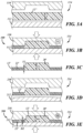
- an exemplary method of making a vehicle interior panel such as the panel 10 of FIGS. 1 and 2 includes sequential first and second pressing steps 100, 200. Only a portion of the mats, tools, and panels are shown in the figures in order to show enlarged views.
- a fiber mat 12" is located between first and second portions 110, 112 of a first compression tool 114 as illustrated in FIG. 3A .
- the first compression tool 114 may be a hot pressing tool in that one or both of the first and second portions 110, 112 are heated tool portions configured to heat the fiber mat 12" when the fiber mat is pressed between the tool portions 110, 112.
- the heating and pressing can be performed in separate sequential steps and/or using separate tools or fixturing.
- the fiber mat 12" is a non-woven component composed of a thermoplastic component and a plurality of entangled fibers.
- the thermoplastic component may one of the types of entangled fibers.
- the fibers may include thermoplastic fibers and/or natural fibers. Suitable natural fibers include but are not limited to hemp, jute, sisal, flax, wool, cotton, wood, and bamboo, to name a few. Suitable thermoplastic fibers include but are not limited to polyolefin fibers, such as polypropylene and its copolymers.
- the thermoplastic component may be in some other form, such as powder.
- the fiber mat 12" is formed from a mixture of individualized natural fibers and thermoplastic fibers in a ratio from 25:75 to 75:25 by weight natural fibers to thermoplastic fibers. In another embodiment, the ratio is in a range from 40:60 to 60:40 or 50:50, within normal manufacturing tolerances. Other types of fibers (e.g., glass, carbon, etc.) are not excluded from use in the mat.
- the fiber mat 12" has a soft, fluffy character with its bulk volume being largely air in its initial form.
- the fiber mat 12" may be formed using methods known in the textile industry such as combing and/or needlepunching the desired types of fibers together to form the mat.
- the fiber mat 12" has a generally uniform initial thickness T which may be in a range from 10 mm to 20 mm, 10 mm to 15 mm, or 10 mm to 12 mm.
- "uniform” means within normal manufacturing tolerances for fiber mats, which may be ⁇ 20% of the nominal thickness.
- the heated tool portions 110, 112 are brought together to heat and at least partially compress the fiber mat 12".
- the hot pressing tool 114 is configured to produce a hot mat or pre-form 12' ( FIG. 3C ) having at least two different thicknesses T1 and T2.
- the tool portions 110, 112 are maintained at a temperature sufficient to soften and/or melt a thermoplastic component (e.g., polypropylene fibers) of the fiber mat 12" such that the mixture of fibers in the mat adhere with one another.
- the thermoplastic fibers may thus act as a hot melt adhesive that joins the other fibers together, with the hot pressing step melting the adhesive and pressing the other fibers into the molten adhesive.
- a first portion 20' of the hot mat 12' has a thickness T1 that is greater than a thickness T2 of a second portion 22' of the hot mat, with the first and second portions 20', 22' corresponding to the respective soft and hard portions 20, 22 of the substrate 12 of FIG. 2 .
- the first thickness T1 is less than or equal to the initial thickness T of the fiber mat 12" (T1 ⁇ T), and the second thickness T2 is less than T1 (T2 ⁇ T1).
- the first thickness T1 is in a range from 20% to 100% of the initial thickness.
- the first thickness T1 is maintained closer to the initial thickness to maximize the cushioning effect in the finished panel.
- Exemplary ranges for T1 include 50% to 100%, 75% to 100%, and 90% to 100% of the initial thickness T.
- the high end of any of these ranges may be less than 100% to ensure the tool contacts the fiber mat 12" and to help remove thickness variations in the as-received fiber mat 12".
- the second portion 22' of the hot mat 12' has a thickness T2 that is less than the initial thickness T and less than the thickness T1 of the first portion 20' of the hot mat.
- the second thickness T2 is in a range from 10% to 40% of the initial thickness T.
- the second thickness T2 is in a range from 15% to 30% of the initial thickness T.
- the hot pressing step 100 reduces the initial thickness T of the fiber mat 12" to within 10-50% of the final thicknesses T S , T H of the panel substrate 12 of FIG. 2 with some room left for final thickness reductions in the second pressing step 200.
- the initial thickness T of the fiber mat 12" is in a range from 10 mm to 12 mm
- the first thickness T1 of the hot mat 12' is in a range from 10 mm to 12 mm (i.e., effectively uncompressed)
- the second thickness T2 of the hot mat is in a range from 2 mm to 3 mm.
- the hot mat 12" is disposed between first and second portions 210, 212 of a second compression tool 214 as illustrated in FIG. 3D .
- the second compression tool 214 may be a molding tool in that a material comprising molten material (i.e., melted fibers in the hot mat 12'), is introduced, formed to shape, and cooled in the tool 214 to retain that shape. While the primary purpose of the first compression tool 114 is to heat the fiber mat 12" and bring it close to its final thickness, the primary purpose of the second compression tool 214 is to bring the mat to its final shape and thickness and to cool the material to solidify the shape.
- the hot mat 12' that is produced remains generally flat with parallel opposite surfaces. At least the second portion 22' having the greater thickness reduction is flat in the illustrated example.
- the elapsed time between removal of the hot mat 12' from the hot pressing tool 114 to the molding tool 214 should be minimized to ensure that the thermoplastic component(s) of the hot mat remain molten at the beginning of the second pressing step 200.
- the cooled tool portions 210, 212 are brought together to shape and cool the hot mat or pre-form 12'.
- the cold pressing tool 214 is configured to produce a compression-formed panel 12 which can be used as the substrate of a vehicle interior panel as in FIGS. 1 and 2 .
- the second pressing step 200 thus introduces contours to the mat-particularly to the portions 22' of the mat that will become the hard or rigid portions 22 that define the overall shape of the finished interior panel 10.
- the tool portions 210, 212 are maintained at a temperature sufficient to harden the molten thermoplastic component of the hot mat 12' such that the other fibers in the mat are adhered together in a final shape.
- the molding tool 214 is configured such that, when the tool is closed on the hot mat 12', a spacing D1 between the between the cooled first and second tool portions 210, 212 is greater at the first portion 20' of the hot mat than a spacing D2 at the second portion 22' of the hot mat. This is to accommodate the greater local thickness T1 of the hot mat to maintain its lower density and softness through the second pressing step 200.
- the hot mat 12' must therefore be carefully aligned and registered with the molding tool 214 so that the thicker portion 20' is co-located with a mold feature (i.e., the recess in the mold portion 210) in order to obtain the compression-formed panel with non-uniform hardness.
- the second compression step 200 thus produces the substrate 12 of a vehicle interior panel as a compression-formed panel having a non-uniform hardness as a result of controlling part thickness and degree of compression during its transformation from a fiber mat 12".
- the tool spacing D1 is equivalent to the thickness T S of the soft portion 20 of the substrate 12
- the tool spacing D2 is equivalent to the thickness T H of the hard portion 22 of the substrate.
- Tool spacing and final part thickness may not be exactly the same to account for dimensional changes (e.g., shrinkage) after demolding.
- D1 may be less than T1
- D2 may be less than T2 to ensure the final desired part thickness is reached.
- the thickness T1 of the first portion 20' of the hot mat 12' is maintained during the second pressing step 200 such that T1 ⁇ T S .
- the thickness T H of the hard portion 22 of the formed panel may be in a range from 50% to 90% of the thickness T2 of the corresponding portion 22' of the hot mat.
- the thickness T2 of the hot mat 12' is in a range from 2 mm to 3 mm, and the thickness T H of the hard portion of the substrate 12 is nominally 2 mm.
- the decorative layer 14 may be disposed over and attached to the formed substrate 12 by any suitable means, such as adhesive bonding, thermal bonding, and/or panel wrapping techniques known in the art.
- the decorative layer 14 may be leather, imitation leather, a polymeric film, fabric, or other desirable material and is arranged over a front side 24 of the substrate 12, which is the side of the substrate that faces the interior of the vehicle in which the panel 10 is installed.
- a compressible backing layer e.g., foam or spacer fabric
- the decorative layer does not include an integrated compressible backing layer (e.g., bi-layer decorative covering).
- additional compressible layers may be employed.
- FIGS. 1 and 2 also includes a line of stitching 26 formed through the substrate 12 and decorative layer 14.
- the line of stitching 26 may be provided for decorative purposes, by simulating a piece-and-sew construction or providing a quilted look.
- the line of stitching 26 can also provide some utility.
- a wrap-attached decorative layer 14 may tend to flatten the locally thick and soft portions 20 of the substrate 12 such that they lose definition in the finished panel.
- the line of stitching 26 can function to locally pull the decorative layer 14 closer to the hard portions 22 of the substrate to allow the cushioned portions 16 of the panel to be more prominent when the stitching is provided along a boundary between the hard and soft portions.
- a line of stitching 26 may be sewn through the decorative layer 14 and the soft portion 20 of the substrate 12 to produce a quilted effect.
- the decorative layer 14 is applied as an integral part of the above-described fiber mat forming process.
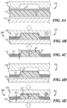
- the decorative layer 14 may for example be present and in contact with the hot mat 12' during the first and/or second pressing steps 100, 200 as in the example of FIGS. 4A-4E .
- the decorative layer 14 is included in the first pressing step 100 and is thus heated and deformed to take the shape of the surface of the hot mat 12' in the first pressing step 100 and is molded along with the hot mat 12' in the second pressing step 200 to form a panel 10 including both the substrate 12 and decorative layer in an adhesiveless process.
- Polymer film decorative layers e.g., simulated leather
- the decorative layer 14 is a fabric layer.
- the fabric layer may be a non-woven fabric layer and, like the fiber mat and resulting panel substrate, may include or be formed from natural fibers and/or thermoplastic fibers. Suitable natural fiber-based fabrics are available under the tradenames Amplitex ® , EcoRein, and FlaxDry. Such decorative layers both reduce the carbon footprint of the vehicle interior panel 10 and make it easier to recycle, particularly where the thermoplastic fibers (e.g., polyolefin) and the natural fibers (e.g., flax) are the same or similar in both the substrate 12 and the decorative layer 14.
- the thermoplastic fibers e.g., polyolefin
- the natural fibers e.g., flax
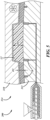
- FIG. 5 schematically illustrates a variation of the disclosed method in which panel stiffening features such as a rib structure 28 are overmolded onto the substrate during the second pressing step 200.
- the molding tool 314 is an injection molding tool and one of the mold portions 312 uses a hot runner system to distribute plastic material to one side of the formed mat/panel to form the rib structure 28.
- the rib structure 28 is formed on a back side of the panel, which is opposite the front side 24 ( FIG. 2 ) and is a non-decorative side.
- This process may be referred to as back injection molding (BIM) and, in this context, represents a solution to a problem created by the innovation of the non-uniform hardness of the substrate.
- BIM back injection molding
- the inventors While the inventors have realized some unexpected advantage to a substrate having non-uniform hardness, it came with new problems to solve.
- One such problem is the lack of a rigid substrate behind the cushioned portion of the panel.
- the substrate provides the rigidity.
- the regions of the panel where the cushioned portions 16 are located may lack structural integrity.
- the BIM structure can provide the missing structural integrity, and it can do so with less material than a solid wall of rigid substrate material.
- the BIM process is performed together with in-mold formation of the decorative layer 14, further reducing the number of distinct process steps and pieces of required manufacturing equipment.
- the overmolding step may be performed on an already formed substrate in a separate operation, or the overmolding step may be performed during the second pressing step 200 but without the decorative layer 14 being present.
- the hard or rigid portions 22 of the formed substrate 12 are relatively impervious to water, for example, due to their relatively high density (e.g., 0.8 g/cm 3 or higher) and their hydrophobic material content, such as polypropylene.
- the natural fibers of the fiber mat 12" may also be processed or pre-treated to increase their hydrophobicity.
- the low density of the soft portions 20 of the substrate 12 can having a wicking effect on moisture in any case, which can also lead to concerns with microbial growth, given the natural fiber content.
- the substrate 12 is treated to prevent microbial or water ingress.
- This treatment may include application of a water-impermeable film (e.g., polypropylene) over the back side of the substrate 12.
- a water-impermeable film e.g., polypropylene
- Such a film can be conveniently applied during the above-described compression forming processes.
- a waterproof coating and/or anti-microbial treatment can be applied to the substrate 12 or panel after formation.
Landscapes
- Engineering & Computer Science (AREA)
- Mechanical Engineering (AREA)
- Textile Engineering (AREA)
- Physics & Mathematics (AREA)
- Fluid Mechanics (AREA)
- Manufacturing & Machinery (AREA)
- Vehicle Interior And Exterior Ornaments, Soundproofing, And Insulation (AREA)
Abstract
A vehicle interior panel includes a substrate with non-uniform hardness, providing cushioned portions of the panel without the need for a distinct cushioning layer. The substrate is made from a mat of natural and synthetic fibers that is heated and pressed so that the pressed mat has thick and thin portions. The thin portions are rigid and structural, and the thick portions are soft. Application of a decorative layer can be incorporated into the process, as can back-injection molding (BIM) for additional structure.
Description
- The present disclosure is related generally to vehicle interior panels and, more particularly, to vehicle interior panels made with materials including natural fibers.
- Attempts have been made to use natural fibers as the reinforcing component in polymer composites since the advent of such composites, but problems with their implementation led to non-organic reinforcements such as glass fibers or mineral fillers dominating the market for decades. In recent years, manufacturers have a renewed interest in natural fiber-based composites as some strive to achieve a net-zero carbon footprint in the near future. Some great strides have been made in the automotive industry and its supply base, but challenges remain.
-
U.S. Patent Application Publication No. 2015/0197069 by Basquin, et al. offers one example of a leading automotive interiors manufacturer advancing the art of natural fiber-reinforced composites. Basquin discloses a method of making a carrier or backing for a vehicle interior panel by hot-pressing mixtures of thermoplastic fibers and natural fibers down to a thickness below 1.0 millimeter, while conventional injection molded polymer composites have a 2.5 mm to 3.0 mm thickness range. However, Basquin does not address another problem related to upholstering such a carrier in a manner that is aesthetically pleasing to consumers, which normally requires a soft foam layer and a decorative skin layer over the panel. - In accordance with one or more embodiments, a method of manufacturing a vehicle interior panel includes pressing a fiber mat between heated first and second tool portions to form a hot mat, and pressing the hot mat between cooled first and second tool portions to form a compression-formed panel. The fiber mat includes natural fibers and thermoplastic fibers. The hot mat has a first portion with a first thickness and a second portion with a second thickness that is less than the first thickness. A spacing between the cooled first and second tool portions is greater at the first portion of the hot mat than at the second portion of the hot mat. The compression-formed panel has a soft portion corresponding to the first portion of the hot mat and a hard portion corresponding to the second portion of the hot mat.
- In various embodiments, the fiber mat has an initial thickness, and the first thickness is in a range from 20% to 100% of the initial thickness.
- In various embodiments, the fiber mat has an initial thickness, and the second thickness is in a range from 10% to 40% of the initial thickness.
- In various embodiments, the compression-formed panel is a substrate of the vehicle interior panel, and the method additionally includes the step of attaching a decorative layer along a side of the substrate that faces an interior of a vehicle when the vehicle interior panel is installed in the vehicle.
- In various embodiments, the decorative layer is in contact with the hot mat during the step of pressing the hot mat and is thereby adhered to the substrate.
- In various embodiments, the decorative layer does not include a compressible backing layer, and the vehicle interior panel has a cushioned portion provided by the soft portion of the substrate.
- In various embodiments, the method additionally includes the step of sewing through the decorative layer and the substrate to form a line of stitching along a boundary between the soft portion and hard portion.
- In various embodiments, the method additionally includes the step of sewing through the decorative layer and the substrate to form a line of stitching through the soft portion.
- In various embodiments, the decorative layer comprises natural fibers and thermoplastic fibers.
- In various embodiments, the thermoplastic fibers of the fiber mat and the thermoplastic fibers of the decorative layer each comprise polyolefin fibers.
- In various embodiments, the method additionally includes the step of overmolding a rib structure onto the compression-formed panel via injection molding.
- In various embodiments, the step of overmolding is performed during the step of pressing the hot mat.
- In various embodiments, the method additionally includes the step of treating the soft portion of the compression-formed panel to prevent microbial or water ingress.
- It is contemplated that any number of the individual features of the above-described embodiments and of any other embodiments reflected in the claims, drawings, or description below can be combined in any combination to define an invention, except where features are incompatible.
- Illustrative embodiments will hereinafter be described in conjunction with the following figures, wherein like numerals denote like elements, and wherein:
-
FIG. 1 is a perspective view of a portion of vehicle interior panel having a substrate with non-uniform hardness; -
FIG. 2 is a cross-sectional view of the panel ofFIG. 1 ; -
FIGS. 3A-3E are cross-sectional views of a fiber mat during an exemplary method of making the interior panel ofFIG. 1 ; -
FIGS. 4A-4E are cross-sectional views of a fiber mat and a decorative layer during an exemplary method of making the interior panel ofFIG. 1 ; and -
FIG. 5 is a schematic cross-sectional view of an alternative step in the method ofFIGS. 4A-4E . - Described below is a vehicle interior panel with a cushioned portion provided by the same piece of material as the panel substrate. The panel substrate has a non-uniform hardness with relatively hard and soft portions and is formed by controlling the amount of compression along a fiber mat used to form the panel substrate. The fiber mat may include a mixture of natural fibers and synthetic fibers as part of a movement toward carbon-neutral manufacturing.
-
FIG. 1 is a perspective view of a portion of an embodiment of a vehicleinterior panel 10, andFIG. 2 is a cross-sectional view of the panel ofFIG. 1 . The illustratedpanel 10 is an insert panel or sub-panel that is a subcomponent of a larger vehicle interior panel, such as an interior door panel. However, the methods and structures described below can be applied to any vehicle interior panel, such as an instrument panel, console panel, seat panel, or roof panel, to name a few examples. Thepanel 10 includes asubstrate 12 and adecorative layer 14 disposed over and/or attached to the substrate. Thepanel 10 has one or more cushionedportions 16 anduncushioned portions 18. "Cushioned" is used here in the sense of upholstery. This means that, when a manual force is applied against the outermost decorative surface of a cushionedportion 16, thepanel 10 locally and elastically compresses and then returns to its original shape when the force is removed. - As referenced above, conventional vehicle interior panels typically employ a three-layer construction with a cushioning layer sandwiched between a decorative outer layer and a rigid or semi-rigid substrate. The illustrated
panel 10 employs asubstrate 12 with non-uniform hardness and can thus provide cushioning without the need for a distinct cushioning layer. Thesubstrate 12 is of unitary construction and includes one or moresoft portions 20 andhard portions 22, where thesoft portions 20 of thesubstrate 12 correspond to the cushionedportions 16 of thepanel 10 and thehard portions 22 of thesubstrate 12 correspond to theuncushioned portions 18 of thepanel 10. "Unitary construction" means thesubstrate 12 is formed as a single, continuous piece from the same material-i.e., without joining separately formed pieces together. "Soft" and "hard" are relative terms-i.e., a hard portion is harder than a soft portion. Also, "hard" and "soft" may alternatively be considered respectively as more or less stiff in bending or as having a higher or lower modulus of elasticity. - As discussed further below, embodiments of the
panel 10 include asubstrate 12 formed from a fiber mat having an initial and generally uniform thickness. Thesubstrate 12 of the finishedpanel 10 has more than one different thickness. In the example ofFIG. 2 , thesoft portion 20 of thesubstrate 12 has a thickness TS that is greater than a thickness TH of thehard portion 22. Additionally, the density of thesoft portion 20 may be less than the density of thehard portion 22. Generally, the density of the substrate material is inversely proportional to its thickness. As shown in the figures, the cushionedportions 16 of thepanel 10 may protrude outwardly with respect to adjacent uncushioned portions and be visibly discernible as aesthetic elements of the panel. There may be intermediate substrate thicknesses along the panel between TS and TH, along with corresponding densities and degrees of cushioning-where larger thickness and lower density correspond to greater degrees of cushioning. - With reference to
FIGS. 3A-3E , an exemplary method of making a vehicle interior panel such as thepanel 10 ofFIGS. 1 and 2 includes sequential first and secondpressing steps pressing step 100 of this example, afiber mat 12" is located between first andsecond portions first compression tool 114 as illustrated inFIG. 3A . Thefirst compression tool 114 may be a hot pressing tool in that one or both of the first andsecond portions fiber mat 12" when the fiber mat is pressed between thetool portions - The
fiber mat 12" is a non-woven component composed of a thermoplastic component and a plurality of entangled fibers. The thermoplastic component may one of the types of entangled fibers. The fibers may include thermoplastic fibers and/or natural fibers. Suitable natural fibers include but are not limited to hemp, jute, sisal, flax, wool, cotton, wood, and bamboo, to name a few. Suitable thermoplastic fibers include but are not limited to polyolefin fibers, such as polypropylene and its copolymers. The thermoplastic component may be in some other form, such as powder. In some embodiments, thefiber mat 12" is formed from a mixture of individualized natural fibers and thermoplastic fibers in a ratio from 25:75 to 75:25 by weight natural fibers to thermoplastic fibers. In another embodiment, the ratio is in a range from 40:60 to 60:40 or 50:50, within normal manufacturing tolerances. Other types of fibers (e.g., glass, carbon, etc.) are not excluded from use in the mat. - The
fiber mat 12" has a soft, fluffy character with its bulk volume being largely air in its initial form. Thefiber mat 12" may be formed using methods known in the textile industry such as combing and/or needlepunching the desired types of fibers together to form the mat. Thefiber mat 12" has a generally uniform initial thickness T which may be in a range from 10 mm to 20 mm, 10 mm to 15 mm, or 10 mm to 12 mm. As used here, "uniform" means within normal manufacturing tolerances for fiber mats, which may be ±20% of the nominal thickness. - In
FIG. 3B , theheated tool portions fiber mat 12". The hotpressing tool 114 is configured to produce a hot mat or pre-form 12' (FIG. 3C ) having at least two different thicknesses T1 and T2. Thetool portions fiber mat 12" such that the mixture of fibers in the mat adhere with one another. The thermoplastic fibers may thus act as a hot melt adhesive that joins the other fibers together, with the hot pressing step melting the adhesive and pressing the other fibers into the molten adhesive. - A first portion 20' of the hot mat 12' has a thickness T1 that is greater than a thickness T2 of a second portion 22' of the hot mat, with the first and second portions 20', 22' corresponding to the respective soft and
hard portions substrate 12 ofFIG. 2 . The first thickness T1 is less than or equal to the initial thickness T of thefiber mat 12" (T1 ≤ T), and the second thickness T2 is less than T1 (T2 < T1). In one embodiment, the first thickness T1 is in a range from 20% to 100% of the initial thickness. Preferably, the first thickness T1 is maintained closer to the initial thickness to maximize the cushioning effect in the finished panel. Exemplary ranges for T1 include 50% to 100%, 75% to 100%, and 90% to 100% of the initial thickness T. The high end of any of these ranges may be less than 100% to ensure the tool contacts thefiber mat 12" and to help remove thickness variations in the as-receivedfiber mat 12". - The second portion 22' of the hot mat 12' has a thickness T2 that is less than the initial thickness T and less than the thickness T1 of the first portion 20' of the hot mat. In one embodiment, the second thickness T2 is in a range from 10% to 40% of the initial thickness T. In another embodiment, the second thickness T2 is in a range from 15% to 30% of the initial thickness T. Generally, the hot
pressing step 100 reduces the initial thickness T of thefiber mat 12" to within 10-50% of the final thicknesses TS, TH of thepanel substrate 12 ofFIG. 2 with some room left for final thickness reductions in the secondpressing step 200. In one example, the initial thickness T of thefiber mat 12" is in a range from 10 mm to 12 mm, the first thickness T1 of the hot mat 12' is in a range from 10 mm to 12 mm (i.e., effectively uncompressed), and the second thickness T2 of the hot mat is in a range from 2 mm to 3 mm. - In preparation for the second
pressing step 200, thehot mat 12" is disposed between first andsecond portions second compression tool 214 as illustrated inFIG. 3D . Thesecond compression tool 214 may be a molding tool in that a material comprising molten material (i.e., melted fibers in the hot mat 12'), is introduced, formed to shape, and cooled in thetool 214 to retain that shape. While the primary purpose of thefirst compression tool 114 is to heat thefiber mat 12" and bring it close to its final thickness, the primary purpose of thesecond compression tool 214 is to bring the mat to its final shape and thickness and to cool the material to solidify the shape. While the first pressing step changes the thickness profile of thefiber mat 12", the hot mat 12' that is produced remains generally flat with parallel opposite surfaces. At least the second portion 22' having the greater thickness reduction is flat in the illustrated example. The elapsed time between removal of the hot mat 12' from the hotpressing tool 114 to themolding tool 214 should be minimized to ensure that the thermoplastic component(s) of the hot mat remain molten at the beginning of the secondpressing step 200. - In
FIG. 3D , the cooledtool portions pressing tool 214 is configured to produce a compression-formedpanel 12 which can be used as the substrate of a vehicle interior panel as inFIGS. 1 and 2 . The secondpressing step 200 thus introduces contours to the mat-particularly to the portions 22' of the mat that will become the hard orrigid portions 22 that define the overall shape of the finishedinterior panel 10. Thetool portions - The
molding tool 214 is configured such that, when the tool is closed on the hot mat 12', a spacing D1 between the between the cooled first andsecond tool portions pressing step 200. The hot mat 12' must therefore be carefully aligned and registered with themolding tool 214 so that the thicker portion 20' is co-located with a mold feature (i.e., the recess in the mold portion 210) in order to obtain the compression-formed panel with non-uniform hardness. - One of ordinary skill in the art would undoubtedly consider such a requirement to align the sheet material with the molding tool to be a disadvantage, because it adds complexity or steps to the manufacturing process. Indeed, conventional compression molding (e.g., thermoforming) requires almost no alignment between the sheet material and the compression mold, so long as the sheet material extends across the entire mold cavity. Nonetheless, the present inventors proceeded in the face of such known disadvantages and have realized the benefit of a compression formed panel with non-uniform hardness that can be used in a vehicle interior panel to reduce the number of components used to make one. A useful property of the
fiber mat 12" is also preserved rather than being fully compressed into a rigid material, as is conventional. - The
second compression step 200 thus produces thesubstrate 12 of a vehicle interior panel as a compression-formed panel having a non-uniform hardness as a result of controlling part thickness and degree of compression during its transformation from afiber mat 12". In the illustrated examples, the tool spacing D1 is equivalent to the thickness TS of thesoft portion 20 of thesubstrate 12, and the tool spacing D2 is equivalent to the thickness TH of thehard portion 22 of the substrate. Tool spacing and final part thickness may not be exactly the same to account for dimensional changes (e.g., shrinkage) after demolding. However, D1 may be less than T1, and D2 may be less than T2 to ensure the final desired part thickness is reached. In one example, the thickness T1 of the first portion 20' of the hot mat 12' is maintained during the secondpressing step 200 such that T1 ≈ TS. The thickness TH of thehard portion 22 of the formed panel may be in a range from 50% to 90% of the thickness T2 of the corresponding portion 22' of the hot mat. In a dimensional example, the thickness T2 of the hot mat 12' is in a range from 2 mm to 3 mm, and the thickness TH of the hard portion of thesubstrate 12 is nominally 2 mm. - With reference again to
FIGS. 1 and 2 , thedecorative layer 14 may be disposed over and attached to the formedsubstrate 12 by any suitable means, such as adhesive bonding, thermal bonding, and/or panel wrapping techniques known in the art. Thedecorative layer 14 may be leather, imitation leather, a polymeric film, fabric, or other desirable material and is arranged over afront side 24 of thesubstrate 12, which is the side of the substrate that faces the interior of the vehicle in which thepanel 10 is installed. Advantageously, embodiments of thepanel 10 do not include a compressible backing layer (e.g., foam or spacer fabric) between thesubstrate 12 anddecorative layer 14, and the decorative layer does not include an integrated compressible backing layer (e.g., bi-layer decorative covering). Stated differently, there is no foam or spacer fabric between the compression-formed material and the visible skin layer of the panel. Of course, where desired, additional compressible layers may be employed. - The example of
FIGS. 1 and 2 also includes a line ofstitching 26 formed through thesubstrate 12 anddecorative layer 14. The line ofstitching 26 may be provided for decorative purposes, by simulating a piece-and-sew construction or providing a quilted look. The line ofstitching 26 can also provide some utility. For example, a wrap-attacheddecorative layer 14 may tend to flatten the locally thick andsoft portions 20 of thesubstrate 12 such that they lose definition in the finished panel. The line ofstitching 26 can function to locally pull thedecorative layer 14 closer to thehard portions 22 of the substrate to allow the cushionedportions 16 of the panel to be more prominent when the stitching is provided along a boundary between the hard and soft portions. In another example, a line ofstitching 26 may be sewn through thedecorative layer 14 and thesoft portion 20 of thesubstrate 12 to produce a quilted effect. - In other examples, the
decorative layer 14 is applied as an integral part of the above-described fiber mat forming process. Thedecorative layer 14 may for example be present and in contact with the hot mat 12' during the first and/or secondpressing steps FIGS. 4A-4E . Here, thedecorative layer 14 is included in the firstpressing step 100 and is thus heated and deformed to take the shape of the surface of the hot mat 12' in the firstpressing step 100 and is molded along with the hot mat 12' in the secondpressing step 200 to form apanel 10 including both thesubstrate 12 and decorative layer in an adhesiveless process. Polymer film decorative layers (e.g., simulated leather) are particularly suitable for this in-mold application of the decorative layer. In other embodiments, thedecorative layer 14 is a fabric layer. The fabric layer may be a non-woven fabric layer and, like the fiber mat and resulting panel substrate, may include or be formed from natural fibers and/or thermoplastic fibers. Suitable natural fiber-based fabrics are available under the tradenames Amplitex®, EcoRein, and FlaxDry. Such decorative layers both reduce the carbon footprint of the vehicleinterior panel 10 and make it easier to recycle, particularly where the thermoplastic fibers (e.g., polyolefin) and the natural fibers (e.g., flax) are the same or similar in both thesubstrate 12 and thedecorative layer 14. -
FIG. 5 schematically illustrates a variation of the disclosed method in which panel stiffening features such as arib structure 28 are overmolded onto the substrate during the secondpressing step 200. Here, themolding tool 314 is an injection molding tool and one of themold portions 312 uses a hot runner system to distribute plastic material to one side of the formed mat/panel to form therib structure 28. Therib structure 28 is formed on a back side of the panel, which is opposite the front side 24 (FIG. 2 ) and is a non-decorative side. This process may be referred to as back injection molding (BIM) and, in this context, represents a solution to a problem created by the innovation of the non-uniform hardness of the substrate. While the inventors have realized some unexpected advantage to a substrate having non-uniform hardness, it came with new problems to solve. One such problem is the lack of a rigid substrate behind the cushioned portion of the panel. In a typical three-layer construction, the substrate provides the rigidity. But where the substrate provides the cushioning material as in the above examples, the regions of the panel where the cushionedportions 16 are located may lack structural integrity. The BIM structure can provide the missing structural integrity, and it can do so with less material than a solid wall of rigid substrate material. - In the illustrated example, the BIM process is performed together with in-mold formation of the
decorative layer 14, further reducing the number of distinct process steps and pieces of required manufacturing equipment. In other examples, the overmolding step may be performed on an already formed substrate in a separate operation, or the overmolding step may be performed during the secondpressing step 200 but without thedecorative layer 14 being present. - Another by-product of the
multi-hardness panel substrate 12 is in relation to ingress of the atmosphere. The hard orrigid portions 22 of the formedsubstrate 12 are relatively impervious to water, for example, due to their relatively high density (e.g., 0.8 g/cm3 or higher) and their hydrophobic material content, such as polypropylene. The natural fibers of thefiber mat 12" may also be processed or pre-treated to increase their hydrophobicity. However, the low density of thesoft portions 20 of thesubstrate 12 can having a wicking effect on moisture in any case, which can also lead to concerns with microbial growth, given the natural fiber content. In some embodiments, thesubstrate 12 is treated to prevent microbial or water ingress. This treatment may include application of a water-impermeable film (e.g., polypropylene) over the back side of thesubstrate 12. Such a film can be conveniently applied during the above-described compression forming processes. Alternatively, a waterproof coating and/or anti-microbial treatment can be applied to thesubstrate 12 or panel after formation. - It is to be understood that the foregoing is a description of one or more embodiments of the invention. The invention is not limited to the particular embodiment(s) disclosed herein, but rather is defined solely by the claims below. Furthermore, the statements contained in the foregoing description relate to particular embodiments and are not to be construed as limitations on the scope of the invention or on the definition of terms used in the claims, except where a term or phrase is expressly defined above. Various other embodiments and various changes and modifications to the disclosed embodiment(s) will become apparent to those skilled in the art. All such other embodiments, changes, and modifications are intended to come within the scope of the appended claims.
- As used in this specification and claims, the terms "e.g.," "for example," "for instance," "such as," and "like," and the verbs "comprising," "having," "including," and their other verb forms, when used in conjunction with a listing of one or more components or other items, are each to be construed as open-ended, meaning that the listing is not to be considered as excluding other, additional components or items. Other terms are to be construed using their broadest reasonable meaning unless they are used in a context that requires a different interpretation.
Claims (15)
- A method of manufacturing a vehicle interior panel, the method comprising the steps of:(a) pressing a fiber mat comprising natural fibers and thermoplastic fibers between heated first and second tool portions to form a hot mat having a first portion with a first thickness and a second portion with a second thickness that is less than the first thickness; and(b) pressing the hot mat between cooled first and second tool portions to form a compression-formed panel, wherein a spacing between the cooled first and second tool portions is greater at the first portion of the hot mat than at the second portion of the hot mat,whereby the compression-formed panel has a soft portion corresponding to the first portion of the hot mat and a hard portion corresponding to the second portion of the hot mat.
- The method of claim 1, wherein:before step (a), the fiber mat has an initial thickness, andafter step (a), the first thickness is in a range from 20% to 100% of the initial thickness.
- The method of claim 1, wherein:before step (a), the fiber mat has an initial thickness, andafter step (a), the second thickness is in a range from 10% to 40% of the initial thickness.
- The method of any preceding claim, wherein the compression-formed panel is a substrate of the vehicle interior panel, the method further comprising the step of attaching a decorative layer along a side of the substrate that faces an interior of a vehicle when the vehicle interior panel is installed in the vehicle.
- The method of claim 4, wherein the decorative layer is in contact with the hot mat during step (b) and thereby adhered to the substrate.
- The method of claim 4 or claim 5, wherein the decorative layer does not include a compressible backing layer, the vehicle interior panel having a cushioned portion provided by the soft portion of the substrate.
- The method of any of claims 4 to 6, further comprising the step of sewing through the decorative layer and the substrate to form a line of stitching along a boundary between the soft portion and hard portion.
- The method of any of claims 4 to 7, further comprising the step of sewing through the decorative layer and the substrate to form a line of stitching through the soft portion.
- The method of any of claims 4 to 8, wherein the decorative layer comprises natural fibers and thermoplastic fibers.
- The method of claim 9, wherein the thermoplastic fibers of the fiber mat and the thermoplastic fibers of the decorative layer each comprise polyolefin fibers.
- The method of any preceding claim, further comprising the step of overmolding a rib structure onto the compression-formed panel via injection molding.
- The method of claim 11, wherein the step of overmolding is performed during step (b).
- The method of claim 11 or claim 12, wherein the compression-formed panel is a substrate of the vehicle interior panel, the method further comprising the step of attaching a decorative layer along a side of the substrate that faces an interior of a vehicle when the vehicle interior panel is installed in the vehicle.
- The method of claim 13, wherein the decorative layer is in contact with the hot mat during step (b) and thereby adhered to the substrate.
- The method of any preceding claim, further comprising the step of treating the soft portion of the compression-formed panel to prevent microbial or water ingress.
Applications Claiming Priority (1)
| Application Number | Priority Date | Filing Date | Title |
|---|---|---|---|
| US18/125,453 US12589530B2 (en) | 2023-03-23 | 2023-03-23 | Vehicle interior panel with non-uniform hardness |
Publications (1)
| Publication Number | Publication Date |
|---|---|
| EP4434713A1 true EP4434713A1 (en) | 2024-09-25 |
Family
ID=90417459
Family Applications (1)
| Application Number | Title | Priority Date | Filing Date |
|---|---|---|---|
| EP24165120.7A Pending EP4434713A1 (en) | 2023-03-23 | 2024-03-21 | Vehicle interior panel with non-uniform hardness |
Country Status (3)
| Country | Link |
|---|---|
| US (1) | US12589530B2 (en) |
| EP (1) | EP4434713A1 (en) |
| CN (1) | CN118683091A (en) |
Citations (8)
| Publication number | Priority date | Publication date | Assignee | Title |
|---|---|---|---|---|
| GB843154A (en) * | 1956-12-31 | 1960-08-04 | Owens Corning Fiberglass Corp | A process for producing articles of synthetic resin-bonded fibrous glass and articles produced thereby |
| WO2010080967A1 (en) * | 2009-01-09 | 2010-07-15 | Johnson Controls Technology Company | Natural fiber trim panel |
| CN103240890A (en) * | 2013-05-15 | 2013-08-14 | 无锡吉兴汽车声学部件科技有限公司 | Method for preparing noise reduction felt for automobile |
| US20150197069A1 (en) | 2014-01-16 | 2015-07-16 | Faurecia Innenraum Systeme Gmbh | Carrier for a vehicle interior trim part, a vehicle interior trim part, as well as a method for manufacturing a carrier |
| DE102017121661A1 (en) * | 2016-09-20 | 2018-03-22 | Toyota Boshoku Kabushiki Kaisha | Inner part and method for producing the same |
| EP3527432A1 (en) * | 2018-02-20 | 2019-08-21 | Motherson Innovations Company Limited | Lining component for lining an interior of a passenger transport means and method for the production of such a lining component |
| EP3804979A1 (en) * | 2019-10-07 | 2021-04-14 | Lisa Dräxlmaier GmbH | Method for producing a cladding component for a motor vehicle reinforced with natural fibres |
| US20210237323A1 (en) * | 2015-09-23 | 2021-08-05 | Inteva Products, Llc | Method and apparatus for nonwoven trim panels |
Family Cites Families (11)
| Publication number | Priority date | Publication date | Assignee | Title |
|---|---|---|---|---|
| US7122089B2 (en) * | 2003-06-05 | 2006-10-17 | Dzs, L.L.C. | Method of making a textile laminate having pile-like surface |
| JP2006123198A (en) | 2004-10-26 | 2006-05-18 | Kodama Chemical Industry Co Ltd | Resin molded panel and manufacturing method thereof |
| US20060254855A1 (en) | 2005-05-16 | 2006-11-16 | Loftus James E | Fibrous material having densified surface for improved air flow resistance and method of making |
| US8075971B1 (en) * | 2008-09-26 | 2011-12-13 | Norstar Office Products, Inc. | Chair mat |
| US10391736B2 (en) * | 2013-06-11 | 2019-08-27 | Chen-Cheng Huang | Breathable and waterproof composite fabric and a method of making the same |
| DE102014109174A1 (en) | 2014-07-01 | 2016-01-07 | Johnson Controls Interiors Management Gmbh | A method for producing a shaped body from a fiber material and an apparatus for performing the method |
| US20160312389A1 (en) * | 2015-04-24 | 2016-10-27 | Ji Sang Jang | Adhesive Fabric Woven By Circular Knitting And Method For Forming Three-Dimensional Patterns Using The Same |
| WO2017053313A1 (en) | 2015-09-22 | 2017-03-30 | Shanghai Yanfeng Jinqiao Automotive Trim Systems Co. Ltd | Trim component for vehicle interior |
| EP3478539B1 (en) | 2016-06-30 | 2021-07-21 | Shanghai Yanfeng Jinqiao Automotive Trim Systems Co. Ltd | Trim component for vehicle interior |
| US20180290428A1 (en) * | 2017-04-07 | 2018-10-11 | Milliken & Company | Washable Floor Mat with Reinforcement Layer |
| US12369651B2 (en) * | 2023-08-16 | 2025-07-29 | Eby, Inc. | Method for producing garments or bandages |
-
2023
- 2023-03-23 US US18/125,453 patent/US12589530B2/en active Active
-
2024
- 2024-03-21 EP EP24165120.7A patent/EP4434713A1/en active Pending
- 2024-03-22 CN CN202410332549.4A patent/CN118683091A/en active Pending
Patent Citations (8)
| Publication number | Priority date | Publication date | Assignee | Title |
|---|---|---|---|---|
| GB843154A (en) * | 1956-12-31 | 1960-08-04 | Owens Corning Fiberglass Corp | A process for producing articles of synthetic resin-bonded fibrous glass and articles produced thereby |
| WO2010080967A1 (en) * | 2009-01-09 | 2010-07-15 | Johnson Controls Technology Company | Natural fiber trim panel |
| CN103240890A (en) * | 2013-05-15 | 2013-08-14 | 无锡吉兴汽车声学部件科技有限公司 | Method for preparing noise reduction felt for automobile |
| US20150197069A1 (en) | 2014-01-16 | 2015-07-16 | Faurecia Innenraum Systeme Gmbh | Carrier for a vehicle interior trim part, a vehicle interior trim part, as well as a method for manufacturing a carrier |
| US20210237323A1 (en) * | 2015-09-23 | 2021-08-05 | Inteva Products, Llc | Method and apparatus for nonwoven trim panels |
| DE102017121661A1 (en) * | 2016-09-20 | 2018-03-22 | Toyota Boshoku Kabushiki Kaisha | Inner part and method for producing the same |
| EP3527432A1 (en) * | 2018-02-20 | 2019-08-21 | Motherson Innovations Company Limited | Lining component for lining an interior of a passenger transport means and method for the production of such a lining component |
| EP3804979A1 (en) * | 2019-10-07 | 2021-04-14 | Lisa Dräxlmaier GmbH | Method for producing a cladding component for a motor vehicle reinforced with natural fibres |
Also Published As
| Publication number | Publication date |
|---|---|
| US20240316838A1 (en) | 2024-09-26 |
| US12589530B2 (en) | 2026-03-31 |
| CN118683091A (en) | 2024-09-24 |
Similar Documents
| Publication | Publication Date | Title |
|---|---|---|
| US5456976A (en) | Resiliently padded laminate construction and injection molded thermoplastic articles faced therewith | |
| US5614285A (en) | Molded panel having a decorative facing and made from a blend of natural and plastic fibers | |
| KR101438246B1 (en) | Method of forming a trim panel with a localized deep soft area and trim panel obtained thereby | |
| CA2159364C (en) | Method of making a door panel with integrated bolster | |
| KR101340128B1 (en) | Vehicle component and method for making a vehicle component | |
| CN101119834B (en) | Vehicle trim panels with integrated stitching | |
| US9975283B2 (en) | Method for producing at least two-layer components, and component | |
| JP7653910B2 (en) | Load-bearing sandwich panels for passenger cars | |
| WO2008073541A1 (en) | Automotive interior structural components with integral close-out panel | |
| US20060105661A1 (en) | Thermoplastic formed panel, intermediate panel for the fabrication thereof, and method for fabricating said panel and said intermediate panel | |
| CN101547812A (en) | Molded article including decorative element and method of attaching a decorative element to a vehicle component | |
| WO2017165294A1 (en) | Vehicle interior component | |
| US20030162001A1 (en) | Multilayered composite body consisting of leather and thermoplastic elastomers | |
| US20020176980A1 (en) | Interior covering element for a vehicle and method for producing the same | |
| US6299961B1 (en) | Recyclable textile floor coverings with polyalkylene film separation layer | |
| US7943074B2 (en) | Method and tool for producing a plastic component with a decorative layer, a backing layer and an additional molded part attached thereto | |
| JP3235193B2 (en) | Manufacturing method for composite molded products | |
| US12589530B2 (en) | Vehicle interior panel with non-uniform hardness | |
| JP2002028997A (en) | Plate-shaped foamed molded item with skin | |
| KR102131594B1 (en) | Mesh layered car seat cushion having different hardnesses | |
| JP2012228788A (en) | Foamed molding, and method for manufacturing the same | |
| JPS63162350A (en) | Carpet for automobile | |
| JPS63251209A (en) | Manufacturing method of composite molded body | |
| JP2843616B2 (en) | Cushion product and manufacturing method thereof | |
| KR920003234B1 (en) | Automotive interior moldings |
Legal Events
| Date | Code | Title | Description |
|---|---|---|---|
| PUAI | Public reference made under article 153(3) epc to a published international application that has entered the european phase |
Free format text: ORIGINAL CODE: 0009012 |
|
| STAA | Information on the status of an ep patent application or granted ep patent |
Free format text: STATUS: THE APPLICATION HAS BEEN PUBLISHED |
|
| AK | Designated contracting states |
Kind code of ref document: A1 Designated state(s): AL AT BE BG CH CY CZ DE DK EE ES FI FR GB GR HR HU IE IS IT LI LT LU LV MC ME MK MT NL NO PL PT RO RS SE SI SK SM TR |
|
| STAA | Information on the status of an ep patent application or granted ep patent |
Free format text: STATUS: REQUEST FOR EXAMINATION WAS MADE |
|
| 17P | Request for examination filed |
Effective date: 20250320 |