EP4434701A1 - Tooling for producing z-channels in ceramic fiber preforms - Google Patents
Tooling for producing z-channels in ceramic fiber preforms Download PDFInfo
- Publication number
- EP4434701A1 EP4434701A1 EP24163907.9A EP24163907A EP4434701A1 EP 4434701 A1 EP4434701 A1 EP 4434701A1 EP 24163907 A EP24163907 A EP 24163907A EP 4434701 A1 EP4434701 A1 EP 4434701A1
- Authority
- EP
- European Patent Office
- Prior art keywords
- bundle
- needle
- ceramic
- forming
- needles
- Prior art date
- Legal status (The legal status is an assumption and is not a legal conclusion. Google has not performed a legal analysis and makes no representation as to the accuracy of the status listed.)
- Granted
Links
Images



Classifications
-
- B—PERFORMING OPERATIONS; TRANSPORTING
- B26—HAND CUTTING TOOLS; CUTTING; SEVERING
- B26F—PERFORATING; PUNCHING; CUTTING-OUT; STAMPING-OUT; SEVERING BY MEANS OTHER THAN CUTTING
- B26F1/00—Perforating; Punching; Cutting-out; Stamping-out; Apparatus therefor
- B26F1/24—Perforating by needles or pins
-
- B—PERFORMING OPERATIONS; TRANSPORTING
- B26—HAND CUTTING TOOLS; CUTTING; SEVERING
- B26D—CUTTING; DETAILS COMMON TO MACHINES FOR PERFORATING, PUNCHING, CUTTING-OUT, STAMPING-OUT OR SEVERING
- B26D1/00—Cutting through work characterised by the nature or movement of the cutting member or particular materials not otherwise provided for; Apparatus or machines therefor; Cutting members therefor
- B26D1/0006—Cutting members therefor
-
- C—CHEMISTRY; METALLURGY
- C04—CEMENTS; CONCRETE; ARTIFICIAL STONE; CERAMICS; REFRACTORIES
- C04B—LIME, MAGNESIA; SLAG; CEMENTS; COMPOSITIONS THEREOF, e.g. MORTARS, CONCRETE OR LIKE BUILDING MATERIALS; ARTIFICIAL STONE; CERAMICS; REFRACTORIES; TREATMENT OF NATURAL STONE
- C04B35/00—Shaped ceramic products characterised by their composition; Ceramics compositions; Processing powders of inorganic compounds preparatory to the manufacturing of ceramic products
- C04B35/622—Forming processes; Processing powders of inorganic compounds preparatory to the manufacturing of ceramic products
- C04B35/626—Preparing or treating the powders individually or as batches ; preparing or treating macroscopic reinforcing agents for ceramic products, e.g. fibres; mechanical aspects section B
- C04B35/628—Coating the powders or the macroscopic reinforcing agents
- C04B35/62802—Powder coating materials
- C04B35/62828—Non-oxide ceramics
- C04B35/62831—Carbides
- C04B35/62834—Silicon carbide
-
- C—CHEMISTRY; METALLURGY
- C04—CEMENTS; CONCRETE; ARTIFICIAL STONE; CERAMICS; REFRACTORIES
- C04B—LIME, MAGNESIA; SLAG; CEMENTS; COMPOSITIONS THEREOF, e.g. MORTARS, CONCRETE OR LIKE BUILDING MATERIALS; ARTIFICIAL STONE; CERAMICS; REFRACTORIES; TREATMENT OF NATURAL STONE
- C04B35/00—Shaped ceramic products characterised by their composition; Ceramics compositions; Processing powders of inorganic compounds preparatory to the manufacturing of ceramic products
- C04B35/622—Forming processes; Processing powders of inorganic compounds preparatory to the manufacturing of ceramic products
- C04B35/626—Preparing or treating the powders individually or as batches ; preparing or treating macroscopic reinforcing agents for ceramic products, e.g. fibres; mechanical aspects section B
- C04B35/628—Coating the powders or the macroscopic reinforcing agents
- C04B35/62884—Coating the powders or the macroscopic reinforcing agents by gas phase techniques
-
- C—CHEMISTRY; METALLURGY
- C04—CEMENTS; CONCRETE; ARTIFICIAL STONE; CERAMICS; REFRACTORIES
- C04B—LIME, MAGNESIA; SLAG; CEMENTS; COMPOSITIONS THEREOF, e.g. MORTARS, CONCRETE OR LIKE BUILDING MATERIALS; ARTIFICIAL STONE; CERAMICS; REFRACTORIES; TREATMENT OF NATURAL STONE
- C04B35/00—Shaped ceramic products characterised by their composition; Ceramics compositions; Processing powders of inorganic compounds preparatory to the manufacturing of ceramic products
- C04B35/622—Forming processes; Processing powders of inorganic compounds preparatory to the manufacturing of ceramic products
- C04B35/626—Preparing or treating the powders individually or as batches ; preparing or treating macroscopic reinforcing agents for ceramic products, e.g. fibres; mechanical aspects section B
- C04B35/63—Preparing or treating the powders individually or as batches ; preparing or treating macroscopic reinforcing agents for ceramic products, e.g. fibres; mechanical aspects section B using additives specially adapted for forming the products, e.g.. binder binders
- C04B35/632—Organic additives
- C04B35/634—Polymers
-
- C—CHEMISTRY; METALLURGY
- C04—CEMENTS; CONCRETE; ARTIFICIAL STONE; CERAMICS; REFRACTORIES
- C04B—LIME, MAGNESIA; SLAG; CEMENTS; COMPOSITIONS THEREOF, e.g. MORTARS, CONCRETE OR LIKE BUILDING MATERIALS; ARTIFICIAL STONE; CERAMICS; REFRACTORIES; TREATMENT OF NATURAL STONE
- C04B35/00—Shaped ceramic products characterised by their composition; Ceramics compositions; Processing powders of inorganic compounds preparatory to the manufacturing of ceramic products
- C04B35/71—Ceramic products containing macroscopic reinforcing agents
- C04B35/78—Ceramic products containing macroscopic reinforcing agents containing non-metallic materials
- C04B35/80—Fibres, filaments, whiskers, platelets, or the like
-
- D—TEXTILES; PAPER
- D04—BRAIDING; LACE-MAKING; KNITTING; TRIMMINGS; NON-WOVEN FABRICS
- D04H—MAKING TEXTILE FABRICS, e.g. FROM FIBRES OR FILAMENTARY MATERIAL; FABRICS MADE BY SUCH PROCESSES OR APPARATUS, e.g. FELTS, NON-WOVEN FABRICS; COTTON-WOOL; WADDING ; NON-WOVEN FABRICS FROM STAPLE FIBRES, FILAMENTS OR YARNS, BONDED WITH AT LEAST ONE WEB-LIKE MATERIAL DURING THEIR CONSOLIDATION
- D04H18/00—Needling machines
- D04H18/02—Needling machines with needles
-
- B—PERFORMING OPERATIONS; TRANSPORTING
- B26—HAND CUTTING TOOLS; CUTTING; SEVERING
- B26D—CUTTING; DETAILS COMMON TO MACHINES FOR PERFORATING, PUNCHING, CUTTING-OUT, STAMPING-OUT OR SEVERING
- B26D1/00—Cutting through work characterised by the nature or movement of the cutting member or particular materials not otherwise provided for; Apparatus or machines therefor; Cutting members therefor
- B26D1/0006—Cutting members therefor
- B26D2001/002—Materials or surface treatments therefor, e.g. composite materials
-
- C—CHEMISTRY; METALLURGY
- C04—CEMENTS; CONCRETE; ARTIFICIAL STONE; CERAMICS; REFRACTORIES
- C04B—LIME, MAGNESIA; SLAG; CEMENTS; COMPOSITIONS THEREOF, e.g. MORTARS, CONCRETE OR LIKE BUILDING MATERIALS; ARTIFICIAL STONE; CERAMICS; REFRACTORIES; TREATMENT OF NATURAL STONE
- C04B2235/00—Aspects relating to ceramic starting mixtures or sintered ceramic products
- C04B2235/02—Composition of constituents of the starting material or of secondary phases of the final product
- C04B2235/50—Constituents or additives of the starting mixture chosen for their shape or used because of their shape or their physical appearance
- C04B2235/52—Constituents or additives characterised by their shapes
- C04B2235/5208—Fibers
- C04B2235/5216—Inorganic
- C04B2235/522—Oxidic
- C04B2235/5224—Alumina or aluminates
-
- C—CHEMISTRY; METALLURGY
- C04—CEMENTS; CONCRETE; ARTIFICIAL STONE; CERAMICS; REFRACTORIES
- C04B—LIME, MAGNESIA; SLAG; CEMENTS; COMPOSITIONS THEREOF, e.g. MORTARS, CONCRETE OR LIKE BUILDING MATERIALS; ARTIFICIAL STONE; CERAMICS; REFRACTORIES; TREATMENT OF NATURAL STONE
- C04B2235/00—Aspects relating to ceramic starting mixtures or sintered ceramic products
- C04B2235/02—Composition of constituents of the starting material or of secondary phases of the final product
- C04B2235/50—Constituents or additives of the starting mixture chosen for their shape or used because of their shape or their physical appearance
- C04B2235/52—Constituents or additives characterised by their shapes
- C04B2235/5208—Fibers
- C04B2235/5216—Inorganic
- C04B2235/524—Non-oxidic, e.g. borides, carbides, silicides or nitrides
- C04B2235/5244—Silicon carbide
-
- C—CHEMISTRY; METALLURGY
- C04—CEMENTS; CONCRETE; ARTIFICIAL STONE; CERAMICS; REFRACTORIES
- C04B—LIME, MAGNESIA; SLAG; CEMENTS; COMPOSITIONS THEREOF, e.g. MORTARS, CONCRETE OR LIKE BUILDING MATERIALS; ARTIFICIAL STONE; CERAMICS; REFRACTORIES; TREATMENT OF NATURAL STONE
- C04B2235/00—Aspects relating to ceramic starting mixtures or sintered ceramic products
- C04B2235/02—Composition of constituents of the starting material or of secondary phases of the final product
- C04B2235/50—Constituents or additives of the starting mixture chosen for their shape or used because of their shape or their physical appearance
- C04B2235/52—Constituents or additives characterised by their shapes
- C04B2235/5208—Fibers
- C04B2235/5252—Fibers having a specific pre-form
- C04B2235/5256—Two-dimensional, e.g. woven structures
-
- C—CHEMISTRY; METALLURGY
- C04—CEMENTS; CONCRETE; ARTIFICIAL STONE; CERAMICS; REFRACTORIES
- C04B—LIME, MAGNESIA; SLAG; CEMENTS; COMPOSITIONS THEREOF, e.g. MORTARS, CONCRETE OR LIKE BUILDING MATERIALS; ARTIFICIAL STONE; CERAMICS; REFRACTORIES; TREATMENT OF NATURAL STONE
- C04B2235/00—Aspects relating to ceramic starting mixtures or sintered ceramic products
- C04B2235/02—Composition of constituents of the starting material or of secondary phases of the final product
- C04B2235/50—Constituents or additives of the starting mixture chosen for their shape or used because of their shape or their physical appearance
- C04B2235/52—Constituents or additives characterised by their shapes
- C04B2235/5276—Whiskers, spindles, needles or pins
-
- C—CHEMISTRY; METALLURGY
- C04—CEMENTS; CONCRETE; ARTIFICIAL STONE; CERAMICS; REFRACTORIES
- C04B—LIME, MAGNESIA; SLAG; CEMENTS; COMPOSITIONS THEREOF, e.g. MORTARS, CONCRETE OR LIKE BUILDING MATERIALS; ARTIFICIAL STONE; CERAMICS; REFRACTORIES; TREATMENT OF NATURAL STONE
- C04B2235/00—Aspects relating to ceramic starting mixtures or sintered ceramic products
- C04B2235/60—Aspects relating to the preparation, properties or mechanical treatment of green bodies or pre-forms
- C04B2235/614—Gas infiltration of green bodies or pre-forms
Definitions
- the present invention relates to the fabrication of ceramic matrix composites (CMCs) and, more particularly, to CMCs having improved properties for operating in gas turbine engines.
- CMCs ceramic matrix composites
- z-channels can create more direct pathways for reactant gases.
- the metallic needles commonly used to form z-channels can contaminate and/or deform the preform.
- metallic particles from the needles can remain in the preform after needle removal.
- Such particles and the preform ceramic material(s) can have dissimilar thermal and mechanical properties, thus their presence in the final CMC can be detrimental. Improved means for perforating preforms are therefore desirable.
- a needle array suitable for perforating a fibrous preform includes a backplate and a plurality of needles individually removably attached to and extending away from the backplate.
- Each of the plurality of needles includes a bundle of ceramic filaments, a metallic sheath surrounding a first end of the bundle abutting the backplate, and a sharpened point on the second end of the bundle, the second end being oppositely disposed from the first end.
- a method of forming a needle array suitable for perforating a fibrous preform includes arranging a plurality of ceramic filaments in a length-wise manner to form a bundle, coating the bundle with a reinforcing material, wrapping a sheath around the bundle such that the bundle has a sheathed portion at a first end and an exposed portion at a second end, securing the sheath to the bundle using an adhesive material, and forming a needle tip on the second end of the bundle.
- a method of forming a needle suitable for perforating a fibrous preform includes arranging a plurality of ceramic filaments in a length-wise manner to form a bundle, coating the bundle with a reinforcing material, wrapping a sheath around the bundle such that the bundle has a sheathed portion at a first end and an exposed portion at a second end, securing the sheath to the bundle using an adhesive material, and forming a needle tip on the second end of the bundle.
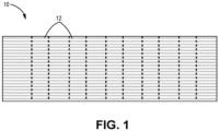
- FIG. 1 is a simplified cross-sectional view of preform 10, which can be formed from ceramic (e.g., silicon carbide - SiC) tows arranged in one of various two or three-dimensional woven architectures such as plain, harness (e.g., 3, 5, 8, etc.), twill, braid, tape layup, or non-symmetric to name a few non-limiting examples.
- Ceramic e.g., silicon carbide - SiC
- Non-woven architectures e.g., chopped, felted, etc.
- a CMC formed from preform 10 can be incorporated into a gas turbine engine. To facilitate more even matrix infiltration during chemical vapor infiltration (CVI), it can be desirable to form z-channels extending through the thickness of preform 10.
- CVI chemical vapor infiltration
- Z-channels provide a much less tortuous pathway along which reactant CVI gases can traversed preform 10.
- a desirable pattern for z-channels 12 is represented in dashed lines in FIG. 1 .
- Z-channels 12 can be formed using needles, which are traditionally formed from a metallic material strong enough to penetrate the ceramic perform (e.g., preform 10). The use of such needles often results in metallic contaminants left in the preform. Accordingly, this disclosure presents the making and use of ceramic needles for z-channel formation.
- FIG. 2 is a simplified perspective view of bundle 14 of ceramic filaments 16.
- Filaments 16 can be relatively large-diameter filaments, for example, with filament diameters of at least 25 microns, and in an exemplary embodiment, between 25 microns and 250 microns. Suitable filament types include SCS-6 monofilaments.
- bundle 14 can be formed from a subset of fibers from a subdivided (e.g., 500-fiber) ceramic tow.
- Each filament (or fiber) 16 can be formed from a ceramic material, such as silicon carbide (SiC), silicon nitride (Si 3 N 4 ), or aluminum oxide (Al 2 O 3 ).
- Each filament 16 can further include an interface coating (IFC) of one or a combination of boron nitride (BN), SiC, Si 3 N 4 , or pyrolytic carbon (PyC), to name a few non-limiting examples, to provide additional toughness to the resulting needle.
- IFC interface coating
- the ceramic selected can be uniform across a given bundle 14 to ensure homogeneity of its mechanical properties.
- Filaments 16 can be arranged in a length-wise manner and secured as bundle 14 by, for example, coating bundle 14.
- FIG. 3 is a simplified plan view of the top of bundle 14, with filaments 16 encased in reinforcing coating 18.
- Coating 18 can be a polymer coating, such as an epoxy resin.
- coating 18 can be a ceramic material deposited using chemical vapor deposition (CVD) or infiltration (CVI), a polymer-derived ceramic material formed by pyrolyzing a preceramic polymer, or a silicon alloy melt.
- bundle 14 further has a width (or diameter) W1.
- FIG. 4 is a simplified perspective view of metallic sheath 20 wrapped around a portion/one end of bundle 14.
- Adhesive material 22 e.g., glue, cement, or solder
- Metallic sheath 20 has a width (or diameter) W2 which can be greater than width W1 of bundle 14.
- FIG. 5 is a simplified perspective view showing bundle 14 after its exposed (i.e., unsheathed) end/tip has been sharpened to a point (i.e., point 24).
- Point 24 can be formed using, for example, a grinding wheel or a jig.
- Rotation of point 24 evenly relative to the grinding wheel or jig can form the generally conical point 24 shown in FIG. 5 .
- a point having an off-axis orientation can be formed by preferentially sharpening one portion of point 24. Because it is formed from the underlying ceramic filaments 16, point 24 is also ceramic. With point 24 formed, the entire arrangement of bundle 14 with metallic sheath 20 becomes needle 26. In some embodiments, needle 26 can undergo CVI for additional SiC coating(s).
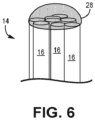
- FIG. 6 is a perspective view of just the exposed portion of bundle 14.
- a bead can be placed on the end of bundle 14 to form beaded tip 28.
- Beaded tip 28 has a rounded shape, and can be used, for example, with certain types of fabric (e.g., loosely woven, low PPI/EPI, etc.) to non-destructively push tows away as it moves through preform 10.
- Beaded tip 28 can be formed from a SiC precursor or polymer material, to name a few non-limiting examples.
- FIG. 7 is a simplified side view of needle array 30 with multiple needles 26 extending from backplate 32.
- each needle 26 includes metallic sheath 20 surrounding a bundle 14 of filaments/fibers, and conical point 24.
- Each needle 26 can be removably connected to backplate 32 via threaded or other engagement with mounts 34.
- Needles 26 can be arranged in columns and rows, or other pattern, and may correspond to infiltration holes of a tooling fixture (not shown) in order to be used with tooling-mounted fixtures. As such, the maximum width of a particular needle (i.e., W2) should be smaller than the diameter of an infiltration hole.
- Needles 26 are individually removable such that damaged needles 26 can be easily replaced, or the particular arrangement of needles 26 altered as desired.
- a preform i.e., preform 10
- any contaminants i.e., ceramic particles from needles 26
- Needles 26 formed from ceramic may also be more durable than metallic needles, with a longer useful life.
- a CMC component formed with the disclosed perforating means can be incorporated into aerospace, maritime, or industrial equipment, to name a few, non-limiting examples.
- a needle array suitable for perforating a fibrous preform includes a backplate and a plurality of needles individually removably attached to and extending away from the backplate.
- Each of the plurality of needles includes a bundle of ceramic filaments, a metallic sheath surrounding a first end of the bundle abutting the backplate, and a sharpened point on the second end of the bundle, the second end being oppositely disposed from the first end.
- each of the ceramic filaments can be formed from one of silicon carbide, silicon nitride, and aluminum oxide.
- each of the ceramic filaments can further include an interface coating of at least one of boron nitride, silicon carbide, silicon nitride, and pyrolytic carbon.
- the bundle of ceramic filaments can further include a reinforcing coating including one of epoxy, a ceramic, a polymer-derived ceramic, and a silicon alloy.
- the metallic sheath can be secured to the bundle of ceramic filaments with an adhesive material.
- a width of the metallic sheath can be greater than a width of the bundle of ceramic filaments.
- a method of forming a needle array suitable for perforating a fibrous preform includes arranging a plurality of ceramic filaments in a length-wise manner to form a bundle, coating the bundle with a reinforcing material, wrapping a sheath around the bundle such that the bundle has a sheathed portion at a first end and an exposed portion at a second end, securing the sheath to the bundle using an adhesive material, and forming a needle tip on the second end of the bundle.
- forming the needle tip can include placing a rounded bead on the second end.
- the rounded bead can be formed from one of a silicon carbide precursor and a polymer material.
- forming the needle tip can include sharpening the second end to form a point.
- the second end can be sharpened using one of a grinding wheel and a jig.
- Any of the above methods can further include attaching each of the plurality of needles to a backplate.
- a method of forming a needle suitable for perforating a fibrous preform includes arranging a plurality of ceramic filaments in a length-wise manner to form a bundle, coating the bundle with a reinforcing material, wrapping a sheath around the bundle such that the bundle has a sheathed portion at a first end and an exposed portion at a second end, securing the sheath to the bundle using an adhesive material, and forming a needle tip on the second end of the bundle.
- forming the needle tip can include placing a rounded bead on the second end.
- the rounded bead can be formed from one of a silicon carbide precursor and a polymer material.
- forming the needle tip can include sharpening the second end to form a point.
- the second end can be sharpened using one of a grinding wheel and a jig.
- Any of the above methods can further include attaching the needle to a backplate.
- the reinforcing coating can include one of epoxy, a ceramic, a polymer-derived ceramic, and a silicon alloy.
- Any of the above methods can further include after forming the needle, applying silicon carbide to the needle using chemical vapor infiltration.
Landscapes
- Engineering & Computer Science (AREA)
- Chemical & Material Sciences (AREA)
- Ceramic Engineering (AREA)
- Manufacturing & Machinery (AREA)
- Organic Chemistry (AREA)
- Materials Engineering (AREA)
- Structural Engineering (AREA)
- Inorganic Chemistry (AREA)
- Life Sciences & Earth Sciences (AREA)
- Forests & Forestry (AREA)
- Mechanical Engineering (AREA)
- Textile Engineering (AREA)
- Chemical Kinetics & Catalysis (AREA)
- Inorganic Fibers (AREA)
- Ceramic Products (AREA)
- Chemical Vapour Deposition (AREA)
Abstract
Description
- The present invention relates to the fabrication of ceramic matrix composites (CMCs) and, more particularly, to CMCs having improved properties for operating in gas turbine engines.
- In the processing of CMCs, there is a need to infiltrate matrix within and around fibrous tows to replace pore volume with dense matrix material. In a woven system, large voids often exist between adjacent tows of a preform. Such voids can become large defects after infiltration of the composite that are detrimental to composite properties. The pore network through a woven system is often highly tortuous for infiltrating reactant vapors, which leads to uneven deposition through the thickness of the preform.
- The formation of z-channels can create more direct pathways for reactant gases. However, the metallic needles commonly used to form z-channels can contaminate and/or deform the preform. For example, metallic particles from the needles can remain in the preform after needle removal. Such particles and the preform ceramic material(s) can have dissimilar thermal and mechanical properties, thus their presence in the final CMC can be detrimental. Improved means for perforating preforms are therefore desirable.
- From a first aspect, there is provided a needle array suitable for perforating a fibrous preform includes a backplate and a plurality of needles individually removably attached to and extending away from the backplate. Each of the plurality of needles includes a bundle of ceramic filaments, a metallic sheath surrounding a first end of the bundle abutting the backplate, and a sharpened point on the second end of the bundle, the second end being oppositely disposed from the first end.
- From another aspect, which the Applicant expressly reserves the right to claim independently, there is provided a method of forming a needle array suitable for perforating a fibrous preform includes arranging a plurality of ceramic filaments in a length-wise manner to form a bundle, coating the bundle with a reinforcing material, wrapping a sheath around the bundle such that the bundle has a sheathed portion at a first end and an exposed portion at a second end, securing the sheath to the bundle using an adhesive material, and forming a needle tip on the second end of the bundle.
- From another aspect, there is provided a method of forming a needle suitable for perforating a fibrous preform includes arranging a plurality of ceramic filaments in a length-wise manner to form a bundle, coating the bundle with a reinforcing material, wrapping a sheath around the bundle such that the bundle has a sheathed portion at a first end and an exposed portion at a second end, securing the sheath to the bundle using an adhesive material, and forming a needle tip on the second end of the bundle.
- Features of embodiments are set forth in the dependent claims.
-
-
FIG. 1 is a simplified cross-sectional view of a fibrous ceramic preform. -
FIG. 2 is a simplified perspective view of a bundle of ceramic filaments. -
FIG. 3 is a simplified plan view of the top of the bundle ofFIG. 2 . -
FIG. 4 is a simplified perspective view of a metallic sheath wrapped around the bundle ofFIG. 2 . -
FIG. 5 is a simplified view of a needle formed after sharpening the end of the sheath-wrapped bundle ofFIG. 4 . -
FIG. 6 is a simplified perspective view of a portion of the bundle with an alternative tip. -
FIG. 7 is a simplified side view of an array of needles. - While the above-identified figures set forth one or more embodiments of the present disclosure, other embodiments are also contemplated, as noted in the discussion. In all cases, this disclosure presents the invention by way of representation and not limitation. It should be understood that numerous other modifications and embodiments can be devised by those skilled in the art, which fall within the scope and spirit of the principles of the invention. The figures may not be drawn to scale, and applications and embodiments of the present invention may include features and components not specifically shown in the drawings.
-
FIG. 1 is a simplified cross-sectional view ofpreform 10, which can be formed from ceramic (e.g., silicon carbide - SiC) tows arranged in one of various two or three-dimensional woven architectures such as plain, harness (e.g., 3, 5, 8, etc.), twill, braid, tape layup, or non-symmetric to name a few non-limiting examples. Non-woven architectures (e.g., chopped, felted, etc.) are also contemplated herein. A CMC formed frompreform 10 can be incorporated into a gas turbine engine. To facilitate more even matrix infiltration during chemical vapor infiltration (CVI), it can be desirable to form z-channels extending through the thickness ofpreform 10. Z-channels provide a much less tortuous pathway along which reactant CVI gases can traversed preform 10. A desirable pattern for z-channels 12 is represented in dashed lines inFIG. 1 . Z-channels 12 can be formed using needles, which are traditionally formed from a metallic material strong enough to penetrate the ceramic perform (e.g., preform 10). The use of such needles often results in metallic contaminants left in the preform. Accordingly, this disclosure presents the making and use of ceramic needles for z-channel formation. -
FIG. 2 is a simplified perspective view ofbundle 14 ofceramic filaments 16.Filaments 16 can be relatively large-diameter filaments, for example, with filament diameters of at least 25 microns, and in an exemplary embodiment, between 25 microns and 250 microns. Suitable filament types include SCS-6 monofilaments. Alternatively,bundle 14 can be formed from a subset of fibers from a subdivided (e.g., 500-fiber) ceramic tow. Each filament (or fiber) 16 can be formed from a ceramic material, such as silicon carbide (SiC), silicon nitride (Si3N4), or aluminum oxide (Al2O3). Eachfilament 16 can further include an interface coating (IFC) of one or a combination of boron nitride (BN), SiC, Si3N4, or pyrolytic carbon (PyC), to name a few non-limiting examples, to provide additional toughness to the resulting needle. The ceramic selected can be uniform across a givenbundle 14 to ensure homogeneity of its mechanical properties.Filaments 16 can be arranged in a length-wise manner and secured asbundle 14 by, for example,coating bundle 14. -
FIG. 3 is a simplified plan view of the top ofbundle 14, withfilaments 16 encased in reinforcingcoating 18.Coating 18 can be a polymer coating, such as an epoxy resin. Alternatively,coating 18 can be a ceramic material deposited using chemical vapor deposition (CVD) or infiltration (CVI), a polymer-derived ceramic material formed by pyrolyzing a preceramic polymer, or a silicon alloy melt. As shown inFIG. 3 ,bundle 14 further has a width (or diameter) W1. - After
individual filaments 16 are secured together,bundle 14 can be further reinforced.FIG. 4 is a simplified perspective view ofmetallic sheath 20 wrapped around a portion/one end ofbundle 14. Adhesive material 22 (e.g., glue, cement, or solder) can securemetallic sheath 20 aroundbundle 14.Metallic sheath 20 has a width (or diameter) W2 which can be greater than width W1 ofbundle 14.FIG. 5 is a simplified perspectiveview showing bundle 14 after its exposed (i.e., unsheathed) end/tip has been sharpened to a point (i.e., point 24).Point 24 can be formed using, for example, a grinding wheel or a jig. Rotation ofpoint 24 evenly relative to the grinding wheel or jig can form the generallyconical point 24 shown inFIG. 5 . In an alternative embodiment, a point having an off-axis orientation can be formed by preferentially sharpening one portion ofpoint 24. Because it is formed from the underlyingceramic filaments 16,point 24 is also ceramic. Withpoint 24 formed, the entire arrangement ofbundle 14 withmetallic sheath 20 becomesneedle 26. In some embodiments,needle 26 can undergo CVI for additional SiC coating(s). -
FIG. 6 is a perspective view of just the exposed portion ofbundle 14. Instead of formingpoint 24, a bead can be placed on the end ofbundle 14 to form beadedtip 28. Beadedtip 28 has a rounded shape, and can be used, for example, with certain types of fabric (e.g., loosely woven, low PPI/EPI, etc.) to non-destructively push tows away as it moves throughpreform 10. Beadedtip 28 can be formed from a SiC precursor or polymer material, to name a few non-limiting examples. -
FIG. 7 is a simplified side view ofneedle array 30 withmultiple needles 26 extending frombackplate 32. As shown, eachneedle 26 includesmetallic sheath 20 surrounding abundle 14 of filaments/fibers, andconical point 24. Eachneedle 26 can be removably connected to backplate 32 via threaded or other engagement with mounts 34.Needles 26 can be arranged in columns and rows, or other pattern, and may correspond to infiltration holes of a tooling fixture (not shown) in order to be used with tooling-mounted fixtures. As such, the maximum width of a particular needle (i.e., W2) should be smaller than the diameter of an infiltration hole. -
Needles 26 are individually removable such that damaged needles 26 can be easily replaced, or the particular arrangement ofneedles 26 altered as desired. Generally speaking, only the ceramic, unsheathed portion (i.e., portion not covered by metallic sheath 20) ofneedle 26 will be inserted into a preform (i.e., preform 10) for z-channel formation. Thus, any contaminants (i.e., ceramic particles from needles 26) remaining inpreform 10 after z-channel formation can become part of the final CMC component with little detrimental impact on component properties.Needles 26 formed from ceramic may also be more durable than metallic needles, with a longer useful life. - A CMC component formed with the disclosed perforating means can be incorporated into aerospace, maritime, or industrial equipment, to name a few, non-limiting examples.
- The following are non-exclusive descriptions of possible embodiments of the present invention.
- A needle array suitable for perforating a fibrous preform includes a backplate and a plurality of needles individually removably attached to and extending away from the backplate. Each of the plurality of needles includes a bundle of ceramic filaments, a metallic sheath surrounding a first end of the bundle abutting the backplate, and a sharpened point on the second end of the bundle, the second end being oppositely disposed from the first end.
- The needle array of the preceding paragraph can optionally include, additionally and/or alternatively, any one or more of the following features, configurations and/or additional components:
In the above needle array, each of the ceramic filaments can be formed from one of silicon carbide, silicon nitride, and aluminum oxide. - In any of the above needle arrays, each of the ceramic filaments can further include an interface coating of at least one of boron nitride, silicon carbide, silicon nitride, and pyrolytic carbon.
- In any of the above needle arrays, the bundle of ceramic filaments can further include a reinforcing coating including one of epoxy, a ceramic, a polymer-derived ceramic, and a silicon alloy.
- In any of the above needle arrays, the metallic sheath can be secured to the bundle of ceramic filaments with an adhesive material.
- In any of the above needle arrays, a width of the metallic sheath can be greater than a width of the bundle of ceramic filaments.
- A method of forming a needle array suitable for perforating a fibrous preform includes arranging a plurality of ceramic filaments in a length-wise manner to form a bundle, coating the bundle with a reinforcing material, wrapping a sheath around the bundle such that the bundle has a sheathed portion at a first end and an exposed portion at a second end, securing the sheath to the bundle using an adhesive material, and forming a needle tip on the second end of the bundle.
- The method of the preceding paragraph can optionally include, additionally and/or alternatively, any one or more of the following features, configurations and/or additional components:
In the above method, forming the needle tip can include placing a rounded bead on the second end. - In any of the above methods, the rounded bead can be formed from one of a silicon carbide precursor and a polymer material.
- In any of the above methods, forming the needle tip can include sharpening the second end to form a point.
- In any of the above methods, the second end can be sharpened using one of a grinding wheel and a jig.
- Any of the above methods can further include attaching each of the plurality of needles to a backplate.
- A method of forming a needle suitable for perforating a fibrous preform includes arranging a plurality of ceramic filaments in a length-wise manner to form a bundle, coating the bundle with a reinforcing material, wrapping a sheath around the bundle such that the bundle has a sheathed portion at a first end and an exposed portion at a second end, securing the sheath to the bundle using an adhesive material, and forming a needle tip on the second end of the bundle.
- The method of the preceding paragraph can optionally include, additionally and/or alternatively, any one or more of the following features, configurations and/or additional components:
In the above method, forming the needle tip can include placing a rounded bead on the second end. - In any of the above methods, the rounded bead can be formed from one of a silicon carbide precursor and a polymer material.
- In any of the above methods, forming the needle tip can include sharpening the second end to form a point.
- In any of the above methods, the second end can be sharpened using one of a grinding wheel and a jig.
- Any of the above methods can further include attaching the needle to a backplate.
- In any of the above methods, the reinforcing coating can include one of epoxy, a ceramic, a polymer-derived ceramic, and a silicon alloy.
- Any of the above methods can further include after forming the needle, applying silicon carbide to the needle using chemical vapor infiltration.
- While the invention has been described with reference to an exemplary embodiment(s), it will be understood by those skilled in the art that various changes may be made and equivalents may be substituted for elements thereof without departing from the scope of the invention. In addition, many modifications may be made to adapt a particular situation or material to the teachings of the invention without departing from the essential scope thereof. Therefore, it is intended that the invention not be limited to the particular embodiment(s) disclosed, but that the invention will include all embodiments falling within the scope of the appended claims.
Claims (15)
- A needle array (30) suitable for perforating a fibrous preform (10), the needle array (30) comprising:a backplate (32); anda plurality of needles (26) individually removably attached to and extending away from the backplate (32), each of the plurality of needles (26) comprising:a bundle (14) of ceramic filaments (16);a metallic sheath (20) surrounding a first end of the bundle (14) abutting the backplate (32); anda sharpened point (24) on the second end of the bundle (14), the second end being oppositely disposed from the first end.
- The needle array of claim 1, wherein each of the ceramic filaments (16) is formed from one of silicon carbide, silicon nitride, and aluminum oxide.
- The needle array of claim 2, wherein each of the ceramic filaments (16) further comprises an interface coating of at least one of boron nitride, silicon carbide, silicon nitride, and pyrolytic carbon.
- The needle array of claim 2 or 3, wherein the bundle (14) of ceramic filaments (16) further comprises a reinforcing coating (18) of one of epoxy, a ceramic, a polymer-derived ceramic, and a silicon alloy.
- The needle array of any preceding claim, wherein the metallic sheath (20) is secured to the bundle (14) of ceramic filaments (16) with an adhesive material (22).
- The needle array of any preceding claim, wherein a width (W2) of metallic sheath (20) is greater than a width (W 1) of the bundle (14) of ceramic filaments (16).
- A method of forming a needle (26) suitable for perforating a fibrous preform (10), the method comprising:arranging a plurality of ceramic filaments (16) in a length-wise manner to form a bundle (14);coating the bundle (14) with a reinforcing material (18);wrapping a sheath (20) around the bundle (14) such that the bundle (14) has a sheathed portion at a first end and an exposed portion at a second end;securing the sheath (20) to the bundle (14) using an adhesive material (22); andforming a needle tip (24) on the second end of the bundle (14).
- The method of claim 7, wherein forming the needle tip (24) comprises: placing a rounded bead (28) on the second end.
- The method of claim 8, wherein the rounded bead (28) is formed from one of a silicon carbide precursor and a polymer material.
- The method of claim 7, wherein forming the needle tip (24) comprises: sharpening the second end to form a point (24), optionally wherein the second end is sharpened using one of a grinding wheel and a jig.
- The method of any of claims 7 to 10, and further comprising: attaching the needle (26) to a backplate (32).
- The method of any of claims 7 to 11, wherein the reinforcing material (18) comprises one of epoxy, a ceramic, a polymer-derived ceramic, and a silicon alloy.
- The method of any of claims 7 to 12 and further comprising: after forming the needle (26), applying silicon carbide to the needle (26) using chemical vapor infiltration.
- A method of forming a needle array (30) suitable for perforating a fibrous preform (10), the method comprising:
forming a plurality of needles (26), wherein forming each of the plurality of needles (26) comprises the method of forming a needle (26) suitable for perforating a fibrous preform (10) of any of claims 7 to 13. - The method of claim 14 as dependent on claim 11, directly or indirectly, comprising attaching each of the plurality of needles (26) to the backplate (32).
Priority Applications (1)
| Application Number | Priority Date | Filing Date | Title |
|---|---|---|---|
| EP26151399.8A EP4699757A2 (en) | 2023-03-17 | 2024-03-15 | Tooling for producing z-channels in ceramic fiber preforms |
Applications Claiming Priority (1)
| Application Number | Priority Date | Filing Date | Title |
|---|---|---|---|
| US18/123,046 US20240308922A1 (en) | 2023-03-17 | 2023-03-17 | Tooling for producing z-channels in ceramic fiber preforms |
Related Child Applications (1)
| Application Number | Title | Priority Date | Filing Date |
|---|---|---|---|
| EP26151399.8A Division EP4699757A2 (en) | 2023-03-17 | 2024-03-15 | Tooling for producing z-channels in ceramic fiber preforms |
Publications (2)
| Publication Number | Publication Date |
|---|---|
| EP4434701A1 true EP4434701A1 (en) | 2024-09-25 |
| EP4434701B1 EP4434701B1 (en) | 2026-02-04 |
Family
ID=90366044
Family Applications (2)
| Application Number | Title | Priority Date | Filing Date |
|---|---|---|---|
| EP24163907.9A Active EP4434701B1 (en) | 2023-03-17 | 2024-03-15 | Tooling for producing z-channels in ceramic fiber preforms |
| EP26151399.8A Pending EP4699757A2 (en) | 2023-03-17 | 2024-03-15 | Tooling for producing z-channels in ceramic fiber preforms |
Family Applications After (1)
| Application Number | Title | Priority Date | Filing Date |
|---|---|---|---|
| EP26151399.8A Pending EP4699757A2 (en) | 2023-03-17 | 2024-03-15 | Tooling for producing z-channels in ceramic fiber preforms |
Country Status (2)
| Country | Link |
|---|---|
| US (1) | US20240308922A1 (en) |
| EP (2) | EP4434701B1 (en) |
Families Citing this family (4)
| Publication number | Priority date | Publication date | Assignee | Title |
|---|---|---|---|---|
| US20240300861A1 (en) * | 2023-03-07 | 2024-09-12 | Raytheon Technologies Corporation | Method of reducing surface deformation from z-channel creation |
| US12545628B2 (en) * | 2023-03-17 | 2026-02-10 | Rtx Corporation | Sheathed metallic needles for producing z-channels in fibrous preforms |
| US12473236B2 (en) * | 2023-10-20 | 2025-11-18 | Rtx Corporation | Internal tooling configuration for the creation of z-channels in woven ceramic matrix composite preforms |
| US12552085B2 (en) | 2023-10-20 | 2026-02-17 | Rtx Corporation | Z-channeling into a preform via needle perforation in a stand-alone tool |
Citations (3)
| Publication number | Priority date | Publication date | Assignee | Title |
|---|---|---|---|---|
| DE2343646A1 (en) * | 1973-08-30 | 1975-03-27 | Gallus Herrenschuhfabrik H Vog | Porous plastics sheet for shoes - is perforated by conical needles from inner face giving small pores outside |
| WO2014150393A2 (en) * | 2013-03-15 | 2014-09-25 | Lazur Andrew J | Method for producing high strength ceramic matrix composites |
| CN108127937B (en) * | 2017-12-26 | 2021-01-15 | 江苏德晴新材股份有限公司 | Integrative seam needle of combined material needle and line |
Family Cites Families (5)
| Publication number | Priority date | Publication date | Assignee | Title |
|---|---|---|---|---|
| US3877120A (en) * | 1970-02-20 | 1975-04-15 | Toray Industries | Needle board |
| US3680182A (en) * | 1971-05-11 | 1972-08-01 | Crompton & Knowles Corp | Needle board |
| US4767095A (en) * | 1986-12-23 | 1988-08-30 | Fitzgerald John M | Concrete column form |
| US6233797B1 (en) * | 1999-07-13 | 2001-05-22 | Groz Beckert Kg | Felt needle |
| US9856592B2 (en) * | 2016-03-15 | 2018-01-02 | Goodrich Corporation | Methods and systems for forming a fibrous preform |
-
2023
- 2023-03-17 US US18/123,046 patent/US20240308922A1/en active Pending
-
2024
- 2024-03-15 EP EP24163907.9A patent/EP4434701B1/en active Active
- 2024-03-15 EP EP26151399.8A patent/EP4699757A2/en active Pending
Patent Citations (3)
| Publication number | Priority date | Publication date | Assignee | Title |
|---|---|---|---|---|
| DE2343646A1 (en) * | 1973-08-30 | 1975-03-27 | Gallus Herrenschuhfabrik H Vog | Porous plastics sheet for shoes - is perforated by conical needles from inner face giving small pores outside |
| WO2014150393A2 (en) * | 2013-03-15 | 2014-09-25 | Lazur Andrew J | Method for producing high strength ceramic matrix composites |
| CN108127937B (en) * | 2017-12-26 | 2021-01-15 | 江苏德晴新材股份有限公司 | Integrative seam needle of combined material needle and line |
Also Published As
| Publication number | Publication date |
|---|---|
| EP4699757A2 (en) | 2026-02-25 |
| US20240308922A1 (en) | 2024-09-19 |
| EP4434701B1 (en) | 2026-02-04 |
Similar Documents
| Publication | Publication Date | Title |
|---|---|---|
| EP4434701B1 (en) | Tooling for producing z-channels in ceramic fiber preforms | |
| EP3173393B1 (en) | Methods for processing ceramic fiber | |
| CA2948950C (en) | Methods of processing ceramic fiber | |
| EP1676822A2 (en) | SiC/SiC composites incorporating uncoated fibers to improve interlaminar strength | |
| CN102256914B (en) | Methods of processing ceramic fibers | |
| EP4541535A1 (en) | Z-channeling into a preform via needle perforation in a stand-alone tool | |
| US12545628B2 (en) | Sheathed metallic needles for producing z-channels in fibrous preforms | |
| US20200039890A1 (en) | Filament winding apparatus and method for ceramic matrix composites | |
| US20250171368A1 (en) | System and method for coating ceramic fiber | |
| EP4454842A1 (en) | Z-channel creation in woven preform by incorporation of pin features into preform tooling | |
| US20240300861A1 (en) | Method of reducing surface deformation from z-channel creation | |
| US11993548B2 (en) | Minimization of chemical vapor infiltration tooling hole length through windows | |
| US20240109816A1 (en) | Ceramic matrix composite tooling for chemical vapor infiltration process | |
| US20230250029A1 (en) | Composites and methods of forming composites having tailored cte | |
| EP4549416A1 (en) | Variable z-channel hole pattern | |
| US20240308927A1 (en) | Three-dimensional weave with sacrificial z-fibers for improved ceramic matrix composite microstructure | |
| US20250128453A1 (en) | Pre-shaped space fillers for small cross section features | |
| KR20190021606A (en) | Manufacturing apparatus for truncated cone type carbon composite and manufacturing method thereof | |
| Narayan | K. Ranji Vaidyanathan, Jagannathan Sankar, Ajit D. Kelkar |
Legal Events
| Date | Code | Title | Description |
|---|---|---|---|
| PUAI | Public reference made under article 153(3) epc to a published international application that has entered the european phase |
Free format text: ORIGINAL CODE: 0009012 |
|
| STAA | Information on the status of an ep patent application or granted ep patent |
Free format text: STATUS: THE APPLICATION HAS BEEN PUBLISHED |
|
| AK | Designated contracting states |
Kind code of ref document: A1 Designated state(s): AL AT BE BG CH CY CZ DE DK EE ES FI FR GB GR HR HU IE IS IT LI LT LU LV MC ME MK MT NL NO PL PT RO RS SE SI SK SM TR |
|
| STAA | Information on the status of an ep patent application or granted ep patent |
Free format text: STATUS: REQUEST FOR EXAMINATION WAS MADE |
|
| 17P | Request for examination filed |
Effective date: 20250324 |
|
| GRAP | Despatch of communication of intention to grant a patent |
Free format text: ORIGINAL CODE: EPIDOSNIGR1 |
|
| STAA | Information on the status of an ep patent application or granted ep patent |
Free format text: STATUS: GRANT OF PATENT IS INTENDED |
|
| INTG | Intention to grant announced |
Effective date: 20250902 |
|
| GRAS | Grant fee paid |
Free format text: ORIGINAL CODE: EPIDOSNIGR3 |
|
| GRAA | (expected) grant |
Free format text: ORIGINAL CODE: 0009210 |
|
| STAA | Information on the status of an ep patent application or granted ep patent |
Free format text: STATUS: THE PATENT HAS BEEN GRANTED |
|
| AK | Designated contracting states |
Kind code of ref document: B1 Designated state(s): AL AT BE BG CH CY CZ DE DK EE ES FI FR GB GR HR HU IE IS IT LI LT LU LV MC ME MK MT NL NO PL PT RO RS SE SI SK SM TR |
|
| REG | Reference to a national code |
Ref country code: CH Ref legal event code: F10 Free format text: ST27 STATUS EVENT CODE: U-0-0-F10-F00 (AS PROVIDED BY THE NATIONAL OFFICE) Effective date: 20260204 Ref country code: GB Ref legal event code: FG4D |
|
| REG | Reference to a national code |
Ref country code: DE Ref legal event code: R096 Ref document number: 602024002350 Country of ref document: DE |
|
| REG | Reference to a national code |
Ref country code: IE Ref legal event code: FG4D |
|
| PGFP | Annual fee paid to national office [announced via postgrant information from national office to epo] |
Ref country code: DE Payment date: 20260319 Year of fee payment: 3 |
|
| PGFP | Annual fee paid to national office [announced via postgrant information from national office to epo] |
Ref country code: AT Payment date: 20260301 Year of fee payment: 3 |
|
| PGFP | Annual fee paid to national office [announced via postgrant information from national office to epo] |
Ref country code: FR Payment date: 20260319 Year of fee payment: 3 |