EP4434696A1 - Adjustment structure of multi-functional vegetable cutter - Google Patents
Adjustment structure of multi-functional vegetable cutter Download PDFInfo
- Publication number
- EP4434696A1 EP4434696A1 EP24165418.5A EP24165418A EP4434696A1 EP 4434696 A1 EP4434696 A1 EP 4434696A1 EP 24165418 A EP24165418 A EP 24165418A EP 4434696 A1 EP4434696 A1 EP 4434696A1
- Authority
- EP
- European Patent Office
- Prior art keywords
- frame
- lifting
- blade bracket
- blade
- locking
- Prior art date
- Legal status (The legal status is an assumption and is not a legal conclusion. Google has not performed a legal analysis and makes no representation as to the accuracy of the status listed.)
- Granted
Links
Images




Classifications
-
- B—PERFORMING OPERATIONS; TRANSPORTING
- B26—HAND CUTTING TOOLS; CUTTING; SEVERING
- B26D—CUTTING; DETAILS COMMON TO MACHINES FOR PERFORATING, PUNCHING, CUTTING-OUT, STAMPING-OUT OR SEVERING
- B26D7/00—Details of apparatus for cutting, cutting-out, stamping-out, punching, perforating, or severing by means other than cutting
- B26D7/26—Means for mounting or adjusting the cutting member; Means for adjusting the stroke of the cutting member
- B26D7/2628—Means for adjusting the position of the cutting member
-
- B—PERFORMING OPERATIONS; TRANSPORTING
- B26—HAND CUTTING TOOLS; CUTTING; SEVERING
- B26D—CUTTING; DETAILS COMMON TO MACHINES FOR PERFORATING, PUNCHING, CUTTING-OUT, STAMPING-OUT OR SEVERING
- B26D1/00—Cutting through work characterised by the nature or movement of the cutting member or particular materials not otherwise provided for; Apparatus or machines therefor; Cutting members therefor
- B26D1/01—Cutting through work characterised by the nature or movement of the cutting member or particular materials not otherwise provided for; Apparatus or machines therefor; Cutting members therefor involving a cutting member which does not travel with the work
- B26D1/04—Cutting through work characterised by the nature or movement of the cutting member or particular materials not otherwise provided for; Apparatus or machines therefor; Cutting members therefor involving a cutting member which does not travel with the work having a linearly-movable cutting member
- B26D1/06—Cutting through work characterised by the nature or movement of the cutting member or particular materials not otherwise provided for; Apparatus or machines therefor; Cutting members therefor involving a cutting member which does not travel with the work having a linearly-movable cutting member wherein the cutting member reciprocates
- B26D1/10—Cutting through work characterised by the nature or movement of the cutting member or particular materials not otherwise provided for; Apparatus or machines therefor; Cutting members therefor involving a cutting member which does not travel with the work having a linearly-movable cutting member wherein the cutting member reciprocates in, or substantially in, a direction parallel to the cutting edge
- B26D1/11—Cutting through work characterised by the nature or movement of the cutting member or particular materials not otherwise provided for; Apparatus or machines therefor; Cutting members therefor involving a cutting member which does not travel with the work having a linearly-movable cutting member wherein the cutting member reciprocates in, or substantially in, a direction parallel to the cutting edge with a plurality of cutting members
-
- B—PERFORMING OPERATIONS; TRANSPORTING
- B26—HAND CUTTING TOOLS; CUTTING; SEVERING
- B26D—CUTTING; DETAILS COMMON TO MACHINES FOR PERFORATING, PUNCHING, CUTTING-OUT, STAMPING-OUT OR SEVERING
- B26D3/00—Cutting work characterised by the nature of the cut made; Apparatus therefor
- B26D3/28—Splitting layers from work; Mutually separating layers by cutting
- B26D3/283—Household devices therefor
-
- B—PERFORMING OPERATIONS; TRANSPORTING
- B26—HAND CUTTING TOOLS; CUTTING; SEVERING
- B26D—CUTTING; DETAILS COMMON TO MACHINES FOR PERFORATING, PUNCHING, CUTTING-OUT, STAMPING-OUT OR SEVERING
- B26D3/00—Cutting work characterised by the nature of the cut made; Apparatus therefor
- B26D3/28—Splitting layers from work; Mutually separating layers by cutting
- B26D3/283—Household devices therefor
- B26D2003/288—Household devices therefor making several incisions and cutting cubes or the like, e.g. so-called "julienne-cutter"
-
- B—PERFORMING OPERATIONS; TRANSPORTING
- B26—HAND CUTTING TOOLS; CUTTING; SEVERING
- B26D—CUTTING; DETAILS COMMON TO MACHINES FOR PERFORATING, PUNCHING, CUTTING-OUT, STAMPING-OUT OR SEVERING
- B26D2210/00—Machines or methods used for cutting special materials
- B26D2210/02—Machines or methods used for cutting special materials for cutting food products, e.g. food slicers
-
- Y—GENERAL TAGGING OF NEW TECHNOLOGICAL DEVELOPMENTS; GENERAL TAGGING OF CROSS-SECTIONAL TECHNOLOGIES SPANNING OVER SEVERAL SECTIONS OF THE IPC; TECHNICAL SUBJECTS COVERED BY FORMER USPC CROSS-REFERENCE ART COLLECTIONS [XRACs] AND DIGESTS
- Y02—TECHNOLOGIES OR APPLICATIONS FOR MITIGATION OR ADAPTATION AGAINST CLIMATE CHANGE
- Y02P—CLIMATE CHANGE MITIGATION TECHNOLOGIES IN THE PRODUCTION OR PROCESSING OF GOODS
- Y02P60/00—Technologies relating to agriculture, livestock or agroalimentary industries
- Y02P60/14—Measures for saving energy, e.g. in green houses
Definitions
- the utility model relates to the technical field of vegetable cutters, and relates to an adjustment structure of a multi-functional vegetable cutter.
- a vegetable cutter is a common food processing device used for cutting food.
- a multi-functional vegetable cutter can cut food into slices or shreds as needed to meet different requirements.
- China utility model patent application No. CN208629506U has disclosed a food cutter.
- the food cutter includes a housing and a cutting mechanism.
- the cutting mechanism includes a cutting portion and a pulling portion configured to control the cutting portion to move back and forth.
- the cutting portion includes a sliding member, a first knife, and a plurality of second knives.
- the sliding member is slidably connected to the housing, and in a process of the pulling portion pulling the sliding member to move back and forth, the food can be cut into slices.
- the state of a second cutting knife can be adjusted separately using a screw pile, but an end portion of the screw pile is difficult to manually adjust and inconvenient to use.
- the screw pile exceeds a cutter, and its layout is not ideal either.
- the utility model provides an adjustment structure of a multi-functional vegetable cutter, and has advantages of a simple structure, convenient operation, and a more proper space layout.
- the first vertical cutting assembly includes a first blade bracket slidably moving in the frame along a height direction and a plurality of first vertical cutting blades penetrating through the lower cutting plane, a lifting frame is slidably disposed in the frame along a length direction, the lifting frame is provided with a pair of first lifting grooves, two ends of the first blade bracket are provided with blade bracket sliders that fit with the first lifting grooves and ascend or descend along a trajectory of the first lifting grooves, the frame is rotatably provided with a knob driving the lifting frame to move, and the knob drives the lifting frame via a gear and a gear rack.
- a gear seat is disposed in the frame, a gear shaft is rotatably disposed in the gear seat, the gear shaft is fixed to a gear, the gear is fixed to a knob, an upper end of the lifting frame is provided with a strip-shaped groove accommodating the gear shaft, and the lifting frame is provided with a gear rack meshed with the gear.
- a bottom of the gear shaft is provided with a locking seat
- the locking seat is provided with a plurality of locking planes
- the locking planes are connected via a curved surface
- a side of the gear seat is provided with a plurality of locking chutes
- a locking block is slidably disposed in the locking chute
- a locking spring is disposed between the locking block and the locking chute
- the locking block abuts against the locking plane.
- the locking seat has four locking planes, and two locking chutes are provided and perpendicular to each other.
- a side wall of the frame is provided with a plurality of strip-shaped chutes, and two sides of the lifting frame are provided with strip-shaped sliders fitting with the strip-shaped chutes.
- two pairs of strip-shaped chutes and two pairs of strip-shaped sliders are provided and located at different heights.
- the upper end of the lower cutting plane is further provided with a second vertical cutting assembly
- the second vertical cutting assembly includes a second blade bracket slidably moving in the frame along the height direction and a plurality of second vertical cutting blades penetrating through the lower cutting plane
- the lifting frame is provided with a pair of second lifting grooves
- two ends of the second blade bracket are provided with blade bracket sliders that fit with the second lifting grooves and ascend or descend along a trajectory of the second lifting grooves
- the first vertical cutting blade and the second vertical cutting blade, as well as the first lifting groove and the second lifting groove are vertically staggered.
- the first blade bracket and the second blade bracket are each provided with a convex structure and a concave structure that fit with each other.
- the first lifting groove includes two horizontal segments and a tilted segment connecting the horizontal segments.
- the first vertical cutting assembly is in an operating state and a retracted state separately; and the second lifting groove includes two horizontal segments and a tilted segment connecting the horizontal segments, when the blade bracket slider of the second blade bracket is located on the two horizontal segments separately, the second vertical cutting assembly is in an operating state and a retracted state separately.
- a lifting cavity accommodating the first blade bracket and the second blade bracket is provided in the frame, two pairs of blade bracket chutes are disposed on two sides of the lifting cavity, the first blade bracket and the second blade bracket are slidably disposed in the two pairs of blade bracket chutes, respectively, and a cover plate fixedly connected to the frame is disposed above the lifting cavity.
- the utility model has the following beneficial effects.
- Numeral references in the figures 1 . housing; 2. cutting mechanism; 3. frame; 4. upper cutting plane; 5. lower cutting plane; 6. parallel cutting blade; 7. first blade bracket; 8. first vertical cutting blade; 9. lifting frame; 10. first lifting groove; 11. knob; 12. gear; 13. gear rack; 14. gear seat; 15. gear shaft; 16. strip-shaped groove; 17. locking plane; 18. curved surface; 19. locking chute; 20. locking block; 21. locking spring; 22. strip-shaped chute; 23. strip-shaped slider; 24. second blade bracket; 25. second vertical cutting blade; 26. second lifting groove; 27. cover plate.
- FIGs. 1 to 8 The utility model is further described below with reference to the accompanying drawings and a specific embodiment. Refer to FIGs. 1 to 8 .
- An adjustment structure of a multi-functional vegetable cutter including a cutting mechanism 2 slidably moving in a housing 1.
- the cutting mechanism 2 includes a frame 3 and an upper cutting plane 4 and a lower cutting plane 5 that are disposed in the frame 3, a lower end of the upper cutting plane 4 is provided with a parallel cutting blade 6, and an upper end of the lower cutting plane 5 is provided with a first vertical cutting assembly.
- the first vertical cutting assembly includes a first blade bracket 7 slidably moving in the frame 3 along a height direction and a plurality of first vertical cutting blades 8 penetrating through the lower cutting plane 5, a lifting frame 9 is slidably disposed in the frame 3 along a length direction, the lifting frame 9 is provided with a pair of first lifting grooves 10, two ends of the first blade bracket 7 are provided with blade bracket sliders that fit with the first lifting grooves 10 and ascend or descend along a trajectory of the first lifting grooves 10, the frame 3 is rotatably provided with a knob 11 driving the lifting frame 9 to move, and the knob 11 drives the lifting frame 9 via a gear 12 and a gear rack 13.
- a gear seat 14 is disposed in the frame 3
- a gear shaft 15 is rotatably disposed in the gear seat 14, the gear shaft 15 is fixed to a gear 12, the gear 12 is fixed to a knob 11, an upper end of the lifting frame 9 is provided with a strip-shaped groove 16 accommodating the gear shaft 15, and the lifting frame 9 is provided with a gear rack 13 meshed with the gear 12.
- the process of the knob 11 driving the first vertical cutting assembly to ascend or descend is as follows:
- the knob 11 is rotated manually, and the gear 12 and the gear shaft 15 rotate along with it.
- the gear 12 and the gear rack 13 drive the lifting frame 9 to move vertically.
- the blade bracket slider moves along the trajectory of the first lifting groove 10, to change its position in the height direction, thus further driving the first blade bracket 7 and the first vertical cutting blade 8 to ascend or descend.
- a side wall of the frame 3 is provided with a plurality of strip-shaped chutes 22, and two sides of the lifting frame 9 are provided with strip-shaped sliders 23 fitting with the strip-shaped chutes.
- two pairs of strip-shaped chutes 22 and two pairs of strip-shaped sliders 23 are provided and located at different heights.
- the upper end of the lower cutting plane 5 is further provided with a second vertical cutting assembly
- the second vertical cutting assembly includes a second blade bracket 24 slidably moving in the frame 3 along the height direction and a plurality of second vertical cutting blades 25 penetrating through the lower cutting plane 5
- the lifting frame 9 is provided with a pair of second lifting grooves 26
- two ends of the second blade bracket 24 are provided with blade bracket sliders that fit with the second lifting grooves 26 and ascend or descend along a trajectory of the second lifting grooves 26
- the first vertical cutting blade 8 and the second vertical cutting blade 25, as well as the first lifting groove 10 and the second lifting groove 26, are vertically staggered.
- the first blade bracket 7 and the second blade bracket 24 are each provided with a convex structure and a concave structure that fit with each other.
- the first lifting groove 10 includes two horizontal segments and a tilted segment connecting the horizontal segments.
- the second lifting groove 26 includes two horizontal segments and a tilted segment connecting the horizontal segments, and when the blade bracket slider of the second blade bracket 24 is located on the two horizontal segments separately, the second vertical cutting assembly is in an operating state and a retracted state separately.
- the process of the knob 11 driving the two vertical cutting assemblies is as follows: In an initial state, the blade bracket slider of the first blade bracket 7 and the blade bracket slider of the second blade bracket 24 are both located on the lower horizontal segments, the first vertical cutting blade 8 and the second vertical cutting blade 25 are both in the retracted state.
- the lifting frame 9 is moved up, the blade bracket slider of the first blade bracket 7 moves from the lower horizontal segment onto the upper horizontal segment via the tilted segment, and the blade bracket slider of the second blade bracket 24 slides on the lower horizontal segment all the time. In this case, the first vertical cutting blade 8 extends, and the second vertical cutting blade 25 is still in the retracted state.
- the lifting frame 9 is moved up continuously, the blade bracket slider of the first blade bracket 7 slides on the upper horizontal segment all the time, and the blade bracket slider of the second blade bracket 24 moves onto the upper horizontal segment via the tilted segment.
- the first vertical cutting blade 8 and the second vertical cutting blade 25 both extend.
- a bottom of the gear shaft 15 is provided with a locking seat
- the locking seat is provided with a plurality of locking planes 17, the locking planes 17 are connected via a curved surface 18
- a side of the gear seat 14 is provided with a plurality of locking chutes 19
- a locking block 20 is slidably disposed in the locking chute 19
- a locking spring 21 is disposed between the locking block 20 and the locking chute 19
- the locking block 20 abuts against the locking plane 17.
- the locking seat has four locking planes 17, and two locking chutes 19 are provided and perpendicular to each other. After the locking seat rotates by 90 degrees every time, the locking seat and the locking block 20 form a locking structure.
- the first vertical cutting blade 8 after rotation by 90 degrees from the initial state, the first vertical cutting blade 8 extends, and after another rotation by 90 degrees, the second vertical cutting blade 25 extends. Then, a reverse rotation is performed by 90 degrees, the second vertical cutting blade 25 is retracted, and another reverse rotation is performed by 90 degrees, the first vertical cutting blade 8 is retracted to return to the initial state.
- a lifting cavity accommodating the first blade bracket 7 and the second blade bracket 24 is provided in the frame 3, two pairs of blade bracket chutes are disposed on two sides of the lifting cavity, the first blade bracket 7 and the second blade bracket 24 are slidably disposed in the two pairs of blade bracket chutes, respectively, and a cover plate 27 fixedly connected to the frame 3 is disposed above the lifting cavity.
Landscapes
- Life Sciences & Earth Sciences (AREA)
- Forests & Forestry (AREA)
- Engineering & Computer Science (AREA)
- Mechanical Engineering (AREA)
- Food-Manufacturing Devices (AREA)
- Nonmetal Cutting Devices (AREA)
Abstract
Description
- The utility model relates to the technical field of vegetable cutters, and relates to an adjustment structure of a multi-functional vegetable cutter.
- A vegetable cutter is a common food processing device used for cutting food. A multi-functional vegetable cutter can cut food into slices or shreds as needed to meet different requirements.
- For example, China utility model patent application No.
CN208629506U has disclosed a food cutter. The food cutter includes a housing and a cutting mechanism. The cutting mechanism includes a cutting portion and a pulling portion configured to control the cutting portion to move back and forth. The cutting portion includes a sliding member, a first knife, and a plurality of second knives. The sliding member is slidably connected to the housing, and in a process of the pulling portion pulling the sliding member to move back and forth, the food can be cut into slices. - In the foregoing food cutter, the state of a second cutting knife can be adjusted separately using a screw pile, but an end portion of the screw pile is difficult to manually adjust and inconvenient to use. In addition, the screw pile exceeds a cutter, and its layout is not ideal either.
- In view of the defects in the prior art, the utility model provides an adjustment structure of a multi-functional vegetable cutter, and has advantages of a simple structure, convenient operation, and a more proper space layout.
- To resolve the foregoing technical problem, an objective of the utility model is achieved using the following technical solution.
- An adjustment structure of a multi-functional vegetable cutter is provided, including a cutting mechanism slidably moving in a housing. The cutting mechanism includes a frame and an upper cutting plane and a lower cutting plane that are disposed in the frame, a lower end of the upper cutting plane is provided with a parallel cutting blade, and an upper end of the lower cutting plane is provided with a first vertical cutting assembly. The first vertical cutting assembly includes a first blade bracket slidably moving in the frame along a height direction and a plurality of first vertical cutting blades penetrating through the lower cutting plane, a lifting frame is slidably disposed in the frame along a length direction, the lifting frame is provided with a pair of first lifting grooves, two ends of the first blade bracket are provided with blade bracket sliders that fit with the first lifting grooves and ascend or descend along a trajectory of the first lifting grooves, the frame is rotatably provided with a knob driving the lifting frame to move, and the knob drives the lifting frame via a gear and a gear rack.
- In the foregoing adjustment structure of a multi-functional vegetable cutter, a gear seat is disposed in the frame, a gear shaft is rotatably disposed in the gear seat, the gear shaft is fixed to a gear, the gear is fixed to a knob, an upper end of the lifting frame is provided with a strip-shaped groove accommodating the gear shaft, and the lifting frame is provided with a gear rack meshed with the gear.
- In the foregoing adjustment structure of a multi-functional vegetable cutter, a bottom of the gear shaft is provided with a locking seat, the locking seat is provided with a plurality of locking planes, the locking planes are connected via a curved surface, a side of the gear seat is provided with a plurality of locking chutes, a locking block is slidably disposed in the locking chute, a locking spring is disposed between the locking block and the locking chute, and the locking block abuts against the locking plane. Preferably, the locking seat has four locking planes, and two locking chutes are provided and perpendicular to each other.
- In the foregoing adjustment structure of a multi-functional vegetable cutter, a side wall of the frame is provided with a plurality of strip-shaped chutes, and two sides of the lifting frame are provided with strip-shaped sliders fitting with the strip-shaped chutes. Preferably, two pairs of strip-shaped chutes and two pairs of strip-shaped sliders are provided and located at different heights.
- In the foregoing adjustment structure of a multi-functional vegetable cutter, the upper end of the lower cutting plane is further provided with a second vertical cutting assembly, the second vertical cutting assembly includes a second blade bracket slidably moving in the frame along the height direction and a plurality of second vertical cutting blades penetrating through the lower cutting plane, the lifting frame is provided with a pair of second lifting grooves, two ends of the second blade bracket are provided with blade bracket sliders that fit with the second lifting grooves and ascend or descend along a trajectory of the second lifting grooves, and the first vertical cutting blade and the second vertical cutting blade, as well as the first lifting groove and the second lifting groove, are vertically staggered. Further, the first blade bracket and the second blade bracket are each provided with a convex structure and a concave structure that fit with each other.
- In the foregoing adjustment structure of a multi-functional vegetable cutter, the first lifting groove includes two horizontal segments and a tilted segment connecting the horizontal segments. When the blade bracket slider of the first blade bracket is located on the two horizontal segments separately, the first vertical cutting assembly is in an operating state and a retracted state separately; and the second lifting groove includes two horizontal segments and a tilted segment connecting the horizontal segments, when the blade bracket slider of the second blade bracket is located on the two horizontal segments separately, the second vertical cutting assembly is in an operating state and a retracted state separately.
- In the foregoing adjustment structure of a multi-functional vegetable cutter, a lifting cavity accommodating the first blade bracket and the second blade bracket is provided in the frame, two pairs of blade bracket chutes are disposed on two sides of the lifting cavity, the first blade bracket and the second blade bracket are slidably disposed in the two pairs of blade bracket chutes, respectively, and a cover plate fixedly connected to the frame is disposed above the lifting cavity.
- Compared with the prior art, the utility model has the following beneficial effects.
- 1. The utility model provides an adjustment structure of a vegetable cutter, and a lifting frame is driven, using a knob, to move up and down, so as to adjust the state of the vertical cutting assembly. The utility model has advantages of a simple structure, convenient operation, and a proper space layout.
- 2. The utility model can be further provided with two vertical cutting assemblies, and the same knob can be used to drive the two vertical cutting assemblies to switch the use state, thus easily meeting more use requirements.
- 3. The utility model adds a locking structure at the knob, which can prevent the knob from rotating during vegetable cutting, allowing the vertical cutting assembly to be more stable during operation. Fitting with different locking planes, the locking structure can further provide adjustment positions for the knob, to assist in adjustment of the knob, allowing for more convenient adjustment.
-
-
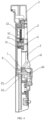
FIG. 1 is a three-dimensional diagram according to the utility model. -
FIG. 2 is a three-dimensional diagram of a cutting mechanism according to the utility model. -
FIG. 3 is another three-dimensional diagram of a cutting mechanism according to the utility model. -
FIG. 4 is a cross-sectional diagram ofFIG. 2 . -
FIG. 5 is a three-dimensional diagram of a driving assembly according to the utility model. -
FIG. 6 is a three-dimensional diagram of a knob assembly according to the utility model. -
FIG. 7 is a three-dimensional diagram of a blade bracket assembly according to the utility model. -
FIG. 8 is a three-dimensional diagram of a lifting frame according to the utility model. - Numeral references in the
figures: 1 . housing; 2. cutting mechanism; 3. frame; 4. upper cutting plane; 5. lower cutting plane; 6. parallel cutting blade; 7. first blade bracket; 8. first vertical cutting blade; 9. lifting frame; 10. first lifting groove; 11. knob; 12. gear; 13. gear rack; 14. gear seat; 15. gear shaft; 16. strip-shaped groove; 17. locking plane; 18. curved surface; 19. locking chute; 20. locking block; 21. locking spring; 22. strip-shaped chute; 23. strip-shaped slider; 24. second blade bracket; 25. second vertical cutting blade; 26. second lifting groove; 27. cover plate. - The utility model is further described below with reference to the accompanying drawings and a specific embodiment. Refer to
FIGs. 1 to 8 . - An adjustment structure of a multi-functional vegetable cutter is provided, including a
cutting mechanism 2 slidably moving in a housing 1. Thecutting mechanism 2 includes a frame 3 and an upper cutting plane 4 and alower cutting plane 5 that are disposed in the frame 3, a lower end of the upper cutting plane 4 is provided with a parallel cutting blade 6, and an upper end of thelower cutting plane 5 is provided with a first vertical cutting assembly. The first vertical cutting assembly includes afirst blade bracket 7 slidably moving in the frame 3 along a height direction and a plurality of firstvertical cutting blades 8 penetrating through thelower cutting plane 5, alifting frame 9 is slidably disposed in the frame 3 along a length direction, thelifting frame 9 is provided with a pair of first liftinggrooves 10, two ends of thefirst blade bracket 7 are provided with blade bracket sliders that fit with thefirst lifting grooves 10 and ascend or descend along a trajectory of thefirst lifting grooves 10, the frame 3 is rotatably provided with aknob 11 driving thelifting frame 9 to move, and theknob 11 drives thelifting frame 9 via agear 12 and agear rack 13. - Referring to
FIG. 5 , agear seat 14 is disposed in the frame 3, agear shaft 15 is rotatably disposed in thegear seat 14, thegear shaft 15 is fixed to agear 12, thegear 12 is fixed to aknob 11, an upper end of thelifting frame 9 is provided with a strip-shapedgroove 16 accommodating thegear shaft 15, and thelifting frame 9 is provided with agear rack 13 meshed with thegear 12. - In this embodiment, the process of the
knob 11 driving the first vertical cutting assembly to ascend or descend is as follows: Theknob 11 is rotated manually, and thegear 12 and thegear shaft 15 rotate along with it. Thegear 12 and thegear rack 13 drive the liftingframe 9 to move vertically. When thelifting frame 9 moves vertically, the blade bracket slider moves along the trajectory of thefirst lifting groove 10, to change its position in the height direction, thus further driving thefirst blade bracket 7 and the firstvertical cutting blade 8 to ascend or descend. - A side wall of the frame 3 is provided with a plurality of strip-shaped
chutes 22, and two sides of thelifting frame 9 are provided with strip-shapedsliders 23 fitting with the strip-shaped chutes. Preferably, two pairs of strip-shapedchutes 22 and two pairs of strip-shapedsliders 23 are provided and located at different heights. - To meet more cutting requirements and obtain finer shreds, the upper end of the
lower cutting plane 5 is further provided with a second vertical cutting assembly, the second vertical cutting assembly includes asecond blade bracket 24 slidably moving in the frame 3 along the height direction and a plurality of secondvertical cutting blades 25 penetrating through thelower cutting plane 5, thelifting frame 9 is provided with a pair ofsecond lifting grooves 26, two ends of thesecond blade bracket 24 are provided with blade bracket sliders that fit with thesecond lifting grooves 26 and ascend or descend along a trajectory of thesecond lifting grooves 26, and the firstvertical cutting blade 8 and the secondvertical cutting blade 25, as well as thefirst lifting groove 10 and thesecond lifting groove 26, are vertically staggered. Further, thefirst blade bracket 7 and thesecond blade bracket 24 are each provided with a convex structure and a concave structure that fit with each other. - The
first lifting groove 10 includes two horizontal segments and a tilted segment connecting the horizontal segments. When the blade bracket slider of thefirst blade bracket 7 is located on the two horizontal segments separately, the first vertical cutting assembly is in an operating state and a retracted state separately. Thesecond lifting groove 26 includes two horizontal segments and a tilted segment connecting the horizontal segments, and when the blade bracket slider of thesecond blade bracket 24 is located on the two horizontal segments separately, the second vertical cutting assembly is in an operating state and a retracted state separately. - In the utility model, the process of the
knob 11 driving the two vertical cutting assemblies is as follows: In an initial state, the blade bracket slider of thefirst blade bracket 7 and the blade bracket slider of thesecond blade bracket 24 are both located on the lower horizontal segments, the firstvertical cutting blade 8 and the secondvertical cutting blade 25 are both in the retracted state. Thelifting frame 9 is moved up, the blade bracket slider of thefirst blade bracket 7 moves from the lower horizontal segment onto the upper horizontal segment via the tilted segment, and the blade bracket slider of thesecond blade bracket 24 slides on the lower horizontal segment all the time. In this case, the firstvertical cutting blade 8 extends, and the secondvertical cutting blade 25 is still in the retracted state. Thelifting frame 9 is moved up continuously, the blade bracket slider of thefirst blade bracket 7 slides on the upper horizontal segment all the time, and the blade bracket slider of thesecond blade bracket 24 moves onto the upper horizontal segment via the tilted segment. In this case, the firstvertical cutting blade 8 and the secondvertical cutting blade 25 both extend. - Referring to
FIG. 6 , a bottom of thegear shaft 15 is provided with a locking seat, the locking seat is provided with a plurality of lockingplanes 17, the locking planes 17 are connected via acurved surface 18, a side of thegear seat 14 is provided with a plurality of lockingchutes 19, a lockingblock 20 is slidably disposed in the lockingchute 19, a lockingspring 21 is disposed between the lockingblock 20 and the lockingchute 19, and the lockingblock 20 abuts against the lockingplane 17. Preferably, the locking seat has four lockingplanes 17, and two lockingchutes 19 are provided and perpendicular to each other. After the locking seat rotates by 90 degrees every time, the locking seat and the lockingblock 20 form a locking structure. Specifically, in this embodiment, after rotation by 90 degrees from the initial state, the firstvertical cutting blade 8 extends, and after another rotation by 90 degrees, the secondvertical cutting blade 25 extends. Then, a reverse rotation is performed by 90 degrees, the secondvertical cutting blade 25 is retracted, and another reverse rotation is performed by 90 degrees, the firstvertical cutting blade 8 is retracted to return to the initial state. - To enable the
first blade bracket 7 and thesecond blade bracket 24 to stably slide along the height direction, a lifting cavity accommodating thefirst blade bracket 7 and thesecond blade bracket 24 is provided in the frame 3, two pairs of blade bracket chutes are disposed on two sides of the lifting cavity, thefirst blade bracket 7 and thesecond blade bracket 24 are slidably disposed in the two pairs of blade bracket chutes, respectively, and acover plate 27 fixedly connected to the frame 3 is disposed above the lifting cavity. - The above embodiment is only a preferred embodiment of the utility model and does not limit the protection scope of the utility model. Therefore, any equivalent changes made based on the structure, shape, principles of the utility model should be included within the protection scope of the utility model.
Claims (7)
- An adjustment structure of a multi-functional vegetable cutter, comprising a cutting mechanism (2) slidably moving in a housing (1), wherein the cutting mechanism (2) comprises a frame (3) and an upper cutting plane (4) and a lower cutting plane (5) that are disposed in the frame (2), a lower end of the upper cutting plane (4) is provided with a parallel cutting blade (6), and an upper end of the lower cutting plane (5) is provided with a first vertical cutting assembly, wherein the first vertical cutting assembly comprises a first blade bracket (7) slidably moving in the frame (3) along a height direction and a plurality of first vertical cutting blades (8) penetrating through the lower cutting plane (5), a lifting frame (9) is slidably disposed in the frame (3) along a length direction, the lifting frame (9) is provided with a pair of first lifting grooves (10), two ends of the first blade bracket (7) are provided with blade bracket sliders that fit with the first lifting grooves (10) and ascend or descend along a trajectory of the first lifting grooves (10), the frame (3) is rotatably provided with a knob (11) driving the lifting frame (9) to move, and the knob (11) drives the lifting frame (9) via a gear (12) and a gear rack (13).
- The adjustment structure of a multi-functional vegetable cutter according to claim 1, wherein a gear seat (14) is disposed in the frame (3), a gear shaft (15) is rotatably disposed in the gear seat (14), the gear shaft (15) is fixed to the gear (12), the gear (12) is fixed to the knob (11), an upper end of the lifting frame (9) is provided with a strip-shaped groove (16) accommodating the gear shaft (15), and the lifting frame (9) is provided with the gear rack (13) meshed with the gear (12).
- The adjustment structure of a multi-functional vegetable cutter according to claim 2, wherein a bottom of the gear shaft (15)is provided with a locking seat, the locking seat is provided with a plurality of locking planes (17), the locking planes (17) are connected via a curved surface (18), a side of the gear seat (14) is provided with a plurality of locking chutes (19), a locking block (20) is slidably disposed in the locking chute (19), a locking spring (21) is disposed between the locking block (20) and the locking chute (19), and the locking block (20) abuts against the locking plane (17).
- The adjustment structure of a multi-functional vegetable cutter according to claim 1, wherein a side wall of the frame (3) is provided with a plurality of strip-shaped chutes (22), and two sides of the lifting frame (9) are provided with strip-shaped sliders (23) fitting with the strip-shaped chutes (22).
- The adjustment structure of a multi-functional vegetable cutter according to claim 1, wherein the upper end of the lower cutting plane (5) is further provided with a second vertical cutting assembly, the second vertical cutting assembly comprises a second blade bracket (24) slidably moving in the frame (3) along the height direction and a plurality of second vertical cutting blades (25) penetrating through the lower cutting plane (5), the lifting frame (9) is provided with a pair of second lifting grooves (26), two ends of the second blade bracket (24) are provided with blade bracket sliders that fit with the second lifting grooves (26) and ascend or descend along a trajectory of the second lifting grooves (26), and the first vertical cutting blade (8) and the second vertical cutting blade (25), as well as the first lifting groove (10) and the second lifting groove (26), are vertically staggered.
- The adjustment structure of a multi-functional vegetable cutter according to claim 5, wherein the first lifting groove (10) comprises two horizontal segments and a tilted segment connecting the horizontal segments, and when the blade bracket slider of the first blade bracket (7) is located on the two horizontal segments separately, the first vertical cutting assembly is in an operating state and a retracted state separately; and the second lifting groove (26) comprises two horizontal segments and a tilted segment connecting the horizontal segments, and when the blade bracket slider of the second blade bracket (24) is located on the two horizontal segments separately, the second vertical cutting assembly is in an operating state and a retracted state separately.
- The adjustment structure of a multi-functional vegetable cutter according to claim 5, wherein a lifting cavity accommodating the first blade bracket (7) and the second blade bracket (24) is provided in the frame (3), two pairs of blade bracket chutes are disposed on two sides of the lifting cavity, the first blade bracket (7) and the second blade bracket (24) are slidably disposed in the two pairs of blade bracket chutes, respectively, and a cover plate (27) fixedly connected to the frame (3) is disposed above the lifting cavity.
Applications Claiming Priority (1)
| Application Number | Priority Date | Filing Date | Title |
|---|---|---|---|
| CN202320638578.4U CN219543291U (en) | 2023-03-24 | 2023-03-24 | Adjusting structure of multifunctional shredder |
Publications (3)
| Publication Number | Publication Date |
|---|---|
| EP4434696A1 true EP4434696A1 (en) | 2024-09-25 |
| EP4434696C0 EP4434696C0 (en) | 2025-09-24 |
| EP4434696B1 EP4434696B1 (en) | 2025-09-24 |
Family
ID=87704490
Family Applications (1)
| Application Number | Title | Priority Date | Filing Date |
|---|---|---|---|
| EP24165418.5A Active EP4434696B1 (en) | 2023-03-24 | 2024-03-22 | Adjustment structure of multi-functional vegetable cutter |
Country Status (3)
| Country | Link |
|---|---|
| US (1) | US12605859B2 (en) |
| EP (1) | EP4434696B1 (en) |
| CN (1) | CN219543291U (en) |
Families Citing this family (1)
| Publication number | Priority date | Publication date | Assignee | Title |
|---|---|---|---|---|
| CN222387106U (en) * | 2024-05-25 | 2025-01-24 | 鲁从强 | Adjusting structure of food cutter |
Citations (3)
| Publication number | Priority date | Publication date | Assignee | Title |
|---|---|---|---|---|
| EP2944441A1 (en) * | 2014-05-12 | 2015-11-18 | Cong Qiang Lu | Vegetable slicer |
| WO2016164273A1 (en) * | 2015-04-06 | 2016-10-13 | Progressive International Corporation | Mandoline slicer |
| CN208629506U (en) | 2018-08-10 | 2019-03-22 | 宁波金舜家居用品有限公司 | Food cutting device |
Family Cites Families (2)
| Publication number | Priority date | Publication date | Assignee | Title |
|---|---|---|---|---|
| EP3294506B1 (en) * | 2015-07-24 | 2022-10-26 | Helen of Troy Limited | Mandoline-type food slicer |
| US11597116B1 (en) * | 2021-09-14 | 2023-03-07 | Progressive International Corp. | Vertical slicer |
-
2023
- 2023-03-24 CN CN202320638578.4U patent/CN219543291U/en active Active
-
2024
- 2024-03-15 US US18/607,123 patent/US12605859B2/en active Active
- 2024-03-22 EP EP24165418.5A patent/EP4434696B1/en active Active
Patent Citations (3)
| Publication number | Priority date | Publication date | Assignee | Title |
|---|---|---|---|---|
| EP2944441A1 (en) * | 2014-05-12 | 2015-11-18 | Cong Qiang Lu | Vegetable slicer |
| WO2016164273A1 (en) * | 2015-04-06 | 2016-10-13 | Progressive International Corporation | Mandoline slicer |
| CN208629506U (en) | 2018-08-10 | 2019-03-22 | 宁波金舜家居用品有限公司 | Food cutting device |
Also Published As
| Publication number | Publication date |
|---|---|
| US12605859B2 (en) | 2026-04-21 |
| US20240316817A1 (en) | 2024-09-26 |
| EP4434696C0 (en) | 2025-09-24 |
| CN219543291U (en) | 2023-08-18 |
| EP4434696B1 (en) | 2025-09-24 |
Similar Documents
| Publication | Publication Date | Title |
|---|---|---|
| US3874259A (en) | Potato cutting machine | |
| CN110978067A (en) | High-speed cutting machine of membrane of cooking convenient to adjust and cut various specifications | |
| US12605859B2 (en) | Adjustment structure of multi-functional vegetable cutter | |
| CN115464695A (en) | A vegetable cutting machine equipped with a knife comb | |
| CN206644034U (en) | One kind slitting adjustable melon and fruit cutting machine of size | |
| CN208468457U (en) | A kind of slicer with thickness regulatory function | |
| CN219171087U (en) | Vegetable cutter convenient to adjust | |
| CN109866263B (en) | An automatic slicer for biomedical research experiments | |
| CN109760119B (en) | A multifunctional vegetable cutter | |
| CN210500400U (en) | Sweet potato processing is with section device | |
| CN215471561U (en) | Position adjusting device of hole cutter of slicing machine | |
| CN212287738U (en) | Household vegetable cutter | |
| CN216266310U (en) | Multidirectional regulation slicer device | |
| CN223419708U (en) | A bread cutting machine | |
| CN202200333U (en) | Adjustable slicer | |
| CN221583689U (en) | Rhizome class chinese-medicinal material section transmission sorting mechanism | |
| CN219552008U (en) | Pathological immunity experiment paraffin section device | |
| CN218285831U (en) | Sweet potato slicing mechanism | |
| CN215318859U (en) | Hand formula vegetables slicer | |
| CN221583836U (en) | Single direction adjusting structure and electric vegetable cutter | |
| CN209599275U (en) | A kind of manual fruits and vegetables food slicer | |
| CN220922647U (en) | Bread slicer cutting mechanism | |
| CN223904030U (en) | Rotary type medicine cutting device for traditional Chinese medicine decoction pieces | |
| CN220008006U (en) | Rotary cutting machine | |
| CN110883833A (en) | Adjustable cutting device for food processing |
Legal Events
| Date | Code | Title | Description |
|---|---|---|---|
| PUAI | Public reference made under article 153(3) epc to a published international application that has entered the european phase |
Free format text: ORIGINAL CODE: 0009012 |
|
| STAA | Information on the status of an ep patent application or granted ep patent |
Free format text: STATUS: THE APPLICATION HAS BEEN PUBLISHED |
|
| AK | Designated contracting states |
Kind code of ref document: A1 Designated state(s): AL AT BE BG CH CY CZ DE DK EE ES FI FR GB GR HR HU IE IS IT LI LT LU LV MC ME MK MT NL NO PL PT RO RS SE SI SK SM TR |
|
| STAA | Information on the status of an ep patent application or granted ep patent |
Free format text: STATUS: REQUEST FOR EXAMINATION WAS MADE |
|
| 17P | Request for examination filed |
Effective date: 20250320 |
|
| GRAP | Despatch of communication of intention to grant a patent |
Free format text: ORIGINAL CODE: EPIDOSNIGR1 |
|
| STAA | Information on the status of an ep patent application or granted ep patent |
Free format text: STATUS: GRANT OF PATENT IS INTENDED |
|
| RIC1 | Information provided on ipc code assigned before grant |
Ipc: B26D 3/28 20060101ALI20250528BHEP Ipc: B26D 7/26 20060101AFI20250528BHEP |
|
| INTG | Intention to grant announced |
Effective date: 20250613 |
|
| GRAS | Grant fee paid |
Free format text: ORIGINAL CODE: EPIDOSNIGR3 |
|
| GRAA | (expected) grant |
Free format text: ORIGINAL CODE: 0009210 |
|
| STAA | Information on the status of an ep patent application or granted ep patent |
Free format text: STATUS: THE PATENT HAS BEEN GRANTED |
|
| AK | Designated contracting states |
Kind code of ref document: B1 Designated state(s): AL AT BE BG CH CY CZ DE DK EE ES FI FR GB GR HR HU IE IS IT LI LT LU LV MC ME MK MT NL NO PL PT RO RS SE SI SK SM TR |
|
| REG | Reference to a national code |
Ref country code: GB Ref legal event code: FG4D |
|
| REG | Reference to a national code |
Ref country code: CH Ref legal event code: EP |
|
| REG | Reference to a national code |
Ref country code: DE Ref legal event code: R096 Ref document number: 602024000723 Country of ref document: DE |
|
| REG | Reference to a national code |
Ref country code: IE Ref legal event code: FG4D |
|
| U01 | Request for unitary effect filed |
Effective date: 20251022 |
|
| U07 | Unitary effect registered |
Designated state(s): AT BE BG DE DK EE FI FR IT LT LU LV MT NL PT RO SE SI Effective date: 20251030 |
|
| PG25 | Lapsed in a contracting state [announced via postgrant information from national office to epo] |
Ref country code: NO Free format text: LAPSE BECAUSE OF FAILURE TO SUBMIT A TRANSLATION OF THE DESCRIPTION OR TO PAY THE FEE WITHIN THE PRESCRIBED TIME-LIMIT Effective date: 20251224 |
|
| PG25 | Lapsed in a contracting state [announced via postgrant information from national office to epo] |
Ref country code: HR Free format text: LAPSE BECAUSE OF FAILURE TO SUBMIT A TRANSLATION OF THE DESCRIPTION OR TO PAY THE FEE WITHIN THE PRESCRIBED TIME-LIMIT Effective date: 20250924 |
|
| PG25 | Lapsed in a contracting state [announced via postgrant information from national office to epo] |
Ref country code: GR Free format text: LAPSE BECAUSE OF FAILURE TO SUBMIT A TRANSLATION OF THE DESCRIPTION OR TO PAY THE FEE WITHIN THE PRESCRIBED TIME-LIMIT Effective date: 20251225 |
|
| PG25 | Lapsed in a contracting state [announced via postgrant information from national office to epo] |
Ref country code: RS Free format text: LAPSE BECAUSE OF FAILURE TO SUBMIT A TRANSLATION OF THE DESCRIPTION OR TO PAY THE FEE WITHIN THE PRESCRIBED TIME-LIMIT Effective date: 20251224 |
|
| PG25 | Lapsed in a contracting state [announced via postgrant information from national office to epo] |
Ref country code: SM Free format text: LAPSE BECAUSE OF FAILURE TO SUBMIT A TRANSLATION OF THE DESCRIPTION OR TO PAY THE FEE WITHIN THE PRESCRIBED TIME-LIMIT Effective date: 20250924 |
|
| PG25 | Lapsed in a contracting state [announced via postgrant information from national office to epo] |
Ref country code: ES Free format text: LAPSE BECAUSE OF FAILURE TO SUBMIT A TRANSLATION OF THE DESCRIPTION OR TO PAY THE FEE WITHIN THE PRESCRIBED TIME-LIMIT Effective date: 20250924 |
|
| PG25 | Lapsed in a contracting state [announced via postgrant information from national office to epo] |
Ref country code: IS Free format text: LAPSE BECAUSE OF FAILURE TO SUBMIT A TRANSLATION OF THE DESCRIPTION OR TO PAY THE FEE WITHIN THE PRESCRIBED TIME-LIMIT Effective date: 20260124 |
|
| PG25 | Lapsed in a contracting state [announced via postgrant information from national office to epo] |
Ref country code: CZ Free format text: LAPSE BECAUSE OF FAILURE TO SUBMIT A TRANSLATION OF THE DESCRIPTION OR TO PAY THE FEE WITHIN THE PRESCRIBED TIME-LIMIT Effective date: 20250924 |
|
| PG25 | Lapsed in a contracting state [announced via postgrant information from national office to epo] |
Ref country code: PL Free format text: LAPSE BECAUSE OF FAILURE TO SUBMIT A TRANSLATION OF THE DESCRIPTION OR TO PAY THE FEE WITHIN THE PRESCRIBED TIME-LIMIT Effective date: 20250924 |
|
| PG25 | Lapsed in a contracting state [announced via postgrant information from national office to epo] |
Ref country code: SK Free format text: LAPSE BECAUSE OF FAILURE TO SUBMIT A TRANSLATION OF THE DESCRIPTION OR TO PAY THE FEE WITHIN THE PRESCRIBED TIME-LIMIT Effective date: 20250924 |
|
| U20 | Renewal fee for the european patent with unitary effect paid |
Year of fee payment: 3 Effective date: 20260319 |
|
| PLBE | No opposition filed within time limit |
Free format text: ORIGINAL CODE: 0009261 |
|
| STAA | Information on the status of an ep patent application or granted ep patent |
Free format text: STATUS: NO OPPOSITION FILED WITHIN TIME LIMIT |
|
| REG | Reference to a national code |
Ref country code: CH Ref legal event code: L10 Free format text: ST27 STATUS EVENT CODE: U-0-0-L10-L00 (AS PROVIDED BY THE NATIONAL OFFICE) Effective date: 20260805 |