EP4434681B1 - Fastener striking tool - Google Patents
Fastener striking tool Download PDFInfo
- Publication number
- EP4434681B1 EP4434681B1 EP22902995.4A EP22902995A EP4434681B1 EP 4434681 B1 EP4434681 B1 EP 4434681B1 EP 22902995 A EP22902995 A EP 22902995A EP 4434681 B1 EP4434681 B1 EP 4434681B1
- Authority
- EP
- European Patent Office
- Prior art keywords
- striker
- separating
- nailing
- passage
- striking tool
- Prior art date
- Legal status (The legal status is an assumption and is not a legal conclusion. Google has not performed a legal analysis and makes no representation as to the accuracy of the status listed.)
- Active
Links
Images


Classifications
-
- B—PERFORMING OPERATIONS; TRANSPORTING
- B25—HAND TOOLS; PORTABLE POWER-DRIVEN TOOLS; MANIPULATORS
- B25C—HAND-HELD NAILING OR STAPLING TOOLS; MANUALLY OPERATED PORTABLE STAPLING TOOLS
- B25C1/00—Hand-held nailing tools; Nail feeding devices
- B25C1/04—Hand-held nailing tools; Nail feeding devices operated by fluid pressure, e.g. by air pressure
- B25C1/047—Mechanical details
-
- B—PERFORMING OPERATIONS; TRANSPORTING
- B25—HAND TOOLS; PORTABLE POWER-DRIVEN TOOLS; MANIPULATORS
- B25C—HAND-HELD NAILING OR STAPLING TOOLS; MANUALLY OPERATED PORTABLE STAPLING TOOLS
- B25C1/00—Hand-held nailing tools; Nail feeding devices
- B25C1/06—Hand-held nailing tools; Nail feeding devices operated by electric power
-
- B—PERFORMING OPERATIONS; TRANSPORTING
- B25—HAND TOOLS; PORTABLE POWER-DRIVEN TOOLS; MANIPULATORS
- B25C—HAND-HELD NAILING OR STAPLING TOOLS; MANUALLY OPERATED PORTABLE STAPLING TOOLS
- B25C7/00—Accessories for nailing or stapling tools, e.g. supports
Definitions
- the shell 10 at the cylinder body 8 extends a grab handle 15 with a button switch downwards, the shell 10 at the holder 4 extends a middle support installed with a motor 12 downwards, the motor 12 drives the driving wheel to rotate through a reducer, and a middle of the nailing passage 1-1 is connected to a nail box 14 installed below.
- a bottom of the grab handle 15 is connected to the middle support by placing a controller 11, and a bottom of the middle support is connected to a bottom of the nail box 14 through a nail box support 13, so as to constitute a Ri-shaped whole structure with better rigidity ("Ri", Pinying of Chinese character).
- a front end of the piston 7 is fixedly connected to a first end of a rod-shaped striker 6 through a threaded hole, a second end of the striker 6 extends along the nailing passage 1-1 of the gun nozzle 1, one side of the rod body is provided with a ratchet, and the rod body at the front section of the ratchet is cylindrical.
- the ratchet of the striker 6 and the driving wheel 5 constitute a one-way intermittent meshing mechanism.
- the piston 7 drives the striker 6 to move back and forth between a compression limiting position (a retracting state of a striking component) and a nailing limiting position (an emission state of the striking component).
- the distance S between the ratchet at the foremost end of the striker 6 and the separating wall 3-2 is 6 mm (determined according to the kinetic energy magnitude and the corresponding cushioning stroke at 3-10mm).
- an end face of one end, adjacent to the piston 7, of the holder 4, is sunk and internally provided with an elastic ring 8', with a better buffering and limiting effect.
- the striker 6 When the motor 12 drives the driving wheel 5 to rotate, the striker 6 may be driven to drive the piston 7 to move in the cylinder body 8, and the compressed air enters the compression chamber 9 for energy storage.
- the driving wheel 5 rotates to its meshing intermittent position, the striker 6 is released instantaneously, and under an action of the compressed air, the nail 2 output to the nail containing chamber 3-3 of the nail base 3 through the nail box 14.
- the separating wall 3-2 blocks the debris and broken nail to enter the abdicating chamber 3-1' and afterward internal space, the part damage, specifically the jam of the drive mechanism caused by the debris, broken nails and various foreign matters are effectively avoided.
- This embodiment is as shown in FIG. 7 to FIG. 10 , and the main structure is also basically the same as the embodiment I. The difference is that, in the striker passage of the nailing passage 1-1 of the gun nozzle 1, a separating locating inclined plane 3-4' inclined downwards is provided, and a separating reed 3-4 is installed at the separating locating inclined plane 3-4'.
- an movable end of the separating reed 3-4 seals a front passage of the striker 6.
- the driving wheel 5 rotates to the meshing intermittent position
- the striker 6 is released instantaneously, and under the action of the compressed air, the nail in the nailing base 3 is struck.
- the separating reed 3-4 is jacked to open through the striker so as to strike the outer circular surface of the striker 6 always.
- the striker 6 is retracted again, the movable end of the separating reed 3-4 is elastically reset, and the front passage of the striker 6 is sealed again. Therefore, the whole working process blocks the debris and broken nail to enter the rear space during the nailing process, so the part damage, specifically the jam of the drive mechanism caused by the debris, broken nails and various foreign matters are effectively avoided.
- the fastener striking tool in this embodiment is as shown in FIG. 11 to FIG. 14 , and the main structure is basically the same as the embodiment III.
- the difference is that the separating wall 3-4" in reducing formation is disposed in the striker passage of the nailing passage 1-1 of the gun nozzle 1 accessed by the nailing base 3, the separating sleeve 3-5 is sleeved at the front section of the striker 6 and a flange is formed at its front end, and when the striker retracting, the flange resists to the separating sleeve 3-5.
- the separating sleeve 3-5 When the striker 6 of the striking component is in the non-nailing retracting position, the separating sleeve 3-5 is retracted correspondingly, and the separating wall 3-4" is sealed. When the striker 6 is released to strike the nail in the nailing base 3, the separating sleeve 3-5 is in an axial free state. When the striker is retracted again, the separating sleeve 3-5 seals the separating wall 3-4" again, so as to prevent the debris and the broken nail entering the rear space during the nailing process, and to prevent the jam of the drive mechanism.
- the above embodiments may effectively avoid the nailing debris and other foreign matters entering inside of the nail gun, so as to avoid the part damage and jam failure.
Landscapes
- Engineering & Computer Science (AREA)
- Mechanical Engineering (AREA)
- Physics & Mathematics (AREA)
- Fluid Mechanics (AREA)
- Portable Nailing Machines And Staplers (AREA)
Description
- The present disclosure relates to a striking tool, in particular to a fastener striking tool, and belongs to the technical field of electric appliances.
- An electric nail gun is a common fastener tool, which fixes one object onto another object in daily life, such as decoration. The electric nail gun is known from
EP 3517250 A1 . - A typical structure of the existing electric nail gun is disclosed by the American patent literature No.
US8267297B2 and includes a compression chamber and a cylinder body located in a shell, and a piston is placed in the cylinder body; the shell is fixedly connected to a holder for supporting a driving wheel, and a nailing base, of which a front end is provided with a gun nozzle, is installed in the holder; the piston is connected to a striker extending to the gun nozzle; and one side of the striker is in one-way intermittent meshing with the driving wheel through a ratchet. In order to avoid interference of a one-way intermittent meshing mechanism during movement, a chamber that is directly communicated with a nailing passage in the gun nozzle is disposed in the nailing base communicating with a nail input box. As a result, not only will debris, during a nail striking process, enter through the chamber and cause damage to internal parts of the nail gun, but also once a nail breaking situation that is hard to avoid, a broken nail will enter the meshing mechanism through the chamber along the gun nozzle, resulting in jam and serious damage. - In order to solve this problem, the American patent literature No.
US10926385B2 - For the above problem in the prior art, through a structure improvement, the present disclosure aims at providing a fastener striking tool capable of preventing foreign matters entering inside, thereby effectively reducing operation failures.
- In order to implement the above purpose, the basic technical solution of the fastener striking tool provided by the present disclosure includes:
- a shell, which is configured to place a compression chamber with gas storage and a cylinder body with a piston inside, and to fix a holder;
- the holder, which is configured to support a driving wheel driven by a motor, and provided with a nailing base of which a front end is provided with a gun nozzle, so as to form a nailing passage extending to the gun nozzle from the cylinder body;
- a striker, which is provided with a first end and a second end and in driving meshing with the driving wheel, the first end is connected to the piston, and the second end extends to the nailing passage along the gun nozzle direction, so as to move back and forth between a compression limiting position and a nailing limiting position;
- wherein the fastener striking tool further includes:
- a separating structure, which is located around the compression limiting position at the second end of the striker, so as to seal a side clearance between the striker and the nailing passage.
- After adopting the present disclosure, since the separating structure blocks the passage, through which the debris and the broken nails can enter inside the nail gun during the nailing process, the part damage and jam failures caused by the debris, broken nails and various foreign matters entering inside are effectively avoided.
- The present disclosure is further described below in combination with drawings.
-
FIG. 1 is a structural schematic diagram of Embodiment I in the present disclosure. -
FIG. 2 is a top view after removing a shell inFIG. 1 . -
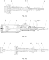
FIG. 3 is a structural schematic diagram of a striking component in a retracting state of Embodiment I in the present disclosure. -
FIG. 4 is a structural schematic diagram of a striking component in an emission state of Embodiment I in the present disclosure. -
FIG. 5 is a structural schematic diagram of a striking component in a retracting state of Embodiment II in the present disclosure. -
FIG. 6 is a structural schematic diagram of a striking component in an emission state of Embodiment II in the present disclosure. -
FIG. 7 is a schematic diagram of a section structure of a striking component of Embodiment III in the present disclosure. -
FIG. 8 is a schematic diagram of a solid structure of striking component of Embodiment III in the present disclosure. -
FIG. 9 is a structural schematic diagram of a striking component in an emission state of Embodiment III in the present disclosure. -
FIG. 10 is a schematic diagram of a striking component in a retracting state of Embodiment III in the present disclosure. -
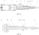
FIG. 11 is a schematic diagram of a section structure of a striking component in an emission state of Embodiment IV in the present disclosure. -
FIG. 12 is a schematic diagram of a local overhead structure inFIG. 11 . -
FIG. 13 is a schematic diagram of a section structure of a striking component in a retracting state of Embodiment IV in the present disclosure. -
FIG. 14 is a schematic diagram of a local overhead structure inFIG. 13 . - A fastener striking tool in this embodiment is as shown in
FIG. 1 to FIG. 4 , acompression chamber 9 sleeved outside acylinder body 8 is placed in ashell 10, so as to store compression gas. Apiston 7, which can compress air energy storage when moving backwards, and release energy for nailing when moving forwards, is placed in thecylinder body 8. Theshell 10 is fixedly connected to aholder 4 for supporting thedriving wheel 5, anailing base 3 of which a front is provided with agun nozzle 1 is fixedly installed at the front of theholder 4, so as to form a nailing passage 1-1 extending to thegun nozzle 1 from thecylinder body 8. Theshell 10 at thecylinder body 8 extends agrab handle 15 with a button switch downwards, theshell 10 at theholder 4 extends a middle support installed with amotor 12 downwards, themotor 12 drives the driving wheel to rotate through a reducer, and a middle of the nailing passage 1-1 is connected to anail box 14 installed below. A bottom of thegrab handle 15 is connected to the middle support by placing acontroller 11, and a bottom of the middle support is connected to a bottom of thenail box 14 through anail box support 13, so as to constitute a Ri-shaped whole structure with better rigidity ("Ri", Pinying of Chinese character). - A front end of the
piston 7 is fixedly connected to a first end of a rod-shaped striker 6 through a threaded hole, a second end of thestriker 6 extends along the nailing passage 1-1 of thegun nozzle 1, one side of the rod body is provided with a ratchet, and the rod body at the front section of the ratchet is cylindrical. The ratchet of thestriker 6 and thedriving wheel 5 constitute a one-way intermittent meshing mechanism. Thepiston 7 drives thestriker 6 to move back and forth between a compression limiting position (a retracting state of a striking component) and a nailing limiting position (an emission state of the striking component). - One end, closing to the
gun nozzle 1, of thenailing base 3, is provided with a nail containing chamber 3-3 communicating with the nailing passage 1-1, one side of the nail containing chamber 3-3 is provided with anail box 14, while one end, closing to thepiston 7, of thenailing base 3, is provided with an abdicating chamber 3-1' capable of containing the striker ratchet. A separating wall 3-2 is provided between the abdicating chamber 3-1' and the nail containing chamber 3-3, the separating wall 3-2 is provided with a circular through hole adapting to the cylinder at the front section of thestriker 6, so as to a separating structure located around the compression limiting position at the second end of thestriker 6, to seal a side clearance between thestriker 6 and the nailing passage 1-1. - In order to ensure to avoid the movement interference, when the
striker 6 is located at the nailing limiting position as shown inFIG. 4 , the distance S between the ratchet at the foremost end of thestriker 6 and the separating wall 3-2 is 6 mm (determined according to the kinetic energy magnitude and the corresponding cushioning stroke at 3-10mm). In addition, an end face of one end, adjacent to thepiston 7, of theholder 4, is sunk and internally provided with an elastic ring 8', with a better buffering and limiting effect. - When the
motor 12 drives thedriving wheel 5 to rotate, thestriker 6 may be driven to drive thepiston 7 to move in thecylinder body 8, and the compressed air enters thecompression chamber 9 for energy storage. When thedriving wheel 5 rotates to its meshing intermittent position, thestriker 6 is released instantaneously, and under an action of the compressed air, thenail 2 output to the nail containing chamber 3-3 of thenail base 3 through thenail box 14. During this process, since the separating wall 3-2 blocks the debris and broken nail to enter the abdicating chamber 3-1' and afterward internal space, the part damage, specifically the jam of the drive mechanism caused by the debris, broken nails and various foreign matters are effectively avoided. - This embodiment is as shown in
FIG. 5 and FIG. 6 , and the main structure is basically the same as the embodiment I. The difference is that a separating ring 3-2' is installed between the abdicating chamber 3-1' and the nail containing chamber 3-3, the separating ring 3-2' is provided with a circular through hole adapting to the cylinder at the front section of thestriker 6, so as to constitute the separating structure. - This embodiment is as shown in
FIG. 7 to FIG. 10 , and the main structure is also basically the same as the embodiment I. The difference is that, in the striker passage of the nailing passage 1-1 of thegun nozzle 1, a separating locating inclined plane 3-4' inclined downwards is provided, and a separating reed 3-4 is installed at the separating locating inclined plane 3-4'. - When the
striker 6 of the striking component is a retracted non-nailing state, an movable end of the separating reed 3-4 seals a front passage of thestriker 6. Once thedriving wheel 5 rotates to the meshing intermittent position, thestriker 6 is released instantaneously, and under the action of the compressed air, the nail in thenailing base 3 is struck. The separating reed 3-4 is jacked to open through the striker so as to strike the outer circular surface of thestriker 6 always. After the nailing is finished, thestriker 6 is retracted again, the movable end of the separating reed 3-4 is elastically reset, and the front passage of thestriker 6 is sealed again. Therefore, the whole working process blocks the debris and broken nail to enter the rear space during the nailing process, so the part damage, specifically the jam of the drive mechanism caused by the debris, broken nails and various foreign matters are effectively avoided. - The fastener striking tool in this embodiment is as shown in
FIG. 11 to FIG. 14 , and the main structure is basically the same as the embodiment III. The difference is that the separating wall 3-4" in reducing formation is disposed in the striker passage of the nailing passage 1-1 of thegun nozzle 1 accessed by the nailingbase 3, the separating sleeve 3-5 is sleeved at the front section of thestriker 6 and a flange is formed at its front end, and when the striker retracting, the flange resists to the separating sleeve 3-5. - When the
striker 6 of the striking component is in the non-nailing retracting position, the separating sleeve 3-5 is retracted correspondingly, and the separating wall 3-4" is sealed. When thestriker 6 is released to strike the nail in thenailing base 3, the separating sleeve 3-5 is in an axial free state. When the striker is retracted again, the separating sleeve 3-5 seals the separating wall 3-4" again, so as to prevent the debris and the broken nail entering the rear space during the nailing process, and to prevent the jam of the drive mechanism. - In conclusion, the above embodiments may effectively avoid the nailing debris and other foreign matters entering inside of the nail gun, so as to avoid the part damage and jam failure.
Claims (9)
- A fastener striking tool, comprising:a shell (10), which is configured to place a compression chamber (9) with gas storage and a cylinder body (8) with a piston (7) inside, and to fix a holder (4);the holder (4), which is configured to support a driving wheel (5) driven by a motor (12), and provided with a nailing base (3) of which a front end is provided with a gun nozzle (1), so as to form a nailing passage (1-1) extending to the gun nozzle (1) from the cylinder body (8);a striker (6), which is provided with a first end and a second end, the first end is connected to the piston (7), and the second end extends to the nailing passage (1-1) along the gun nozzle (1) direction, so as to move back and forth between a compression limiting position and a nailing limiting position; anda separating structure, which is located around the compression limiting position at the second end of the striker (6), so as to seal a side clearance between the striker (6) and the nailing passage (1-1);characterized in that:
the striker (6) is in driving meshing with the driving wheel (5). - The fastener striking tool according to claim 1, wherein one end, adjacent to the gun nozzle (1), of the nailing base (3), is provided with nail containing chamber (3-3) communicating with the nailing passage (1-1), and one end adjacent to the piston (7) is provided with an abdicating chamber (3-1') capable of containing a striker ratchet.
- The fastener striking tool according to claim 2, wherein a separating wall (3-2) is disposed between the abdicating chamber (3-1') and the nail containing chamber (3-3), and the separating wall (3-2) is provided with a circular through hole adapting to a cylinder at a front section of the striker (6), so as to form a separating structure.
- The fastener striking tool according to claim 2, wherein a separating ring (3-2') is disposed between the abdicating chamber (3-1') and the nail containing chamber (3-3), and the separating ring (3-2') is provided with a circular through hole adapting to the cylinder at the front section of the striker (6), so as to form the separating structure.
- The fastener striking tool according to claim 3 or 4, wherein one side of a rod body of the striker (6) is provided with a ratchet that constitutes a one-way intermittent meshing mechanism with the driving wheel (5), and when the striker (6) is located at the nailing limiting position, a distance between the ratchet at a foremost end of the striker (6) and the separating structure is 3-6 mm.
- The fastener striking tool according to claim 1, wherein a separating locating inclined plane (3-4') inclined downwards is disposed in the striker passage of the nailing passage (1-1), and a separating reed (3-4) is installed at the separating locating inclined plane (3-4'), so as to form the separating structure.
- The fastener striking tool according to claim 1, wherein a separating wall (3-4") in reducing formation is disposed in the striker passage of the nailing passage (1-1), a separating sleeve (3-5) is sleeved at a front section of the striker (6), and when the striker (6) is at a retracting position, the separating sleeve (3-5) seals the separating wall (3-4"), so as to form the separating structure.
- The fastener striking tool according to claim 7, wherein a flange is formed at a front end of the striker (6), and when the striker (6) retracts, the flange resists to the separating sleeve (3-5).
- The fastener striking tool according to claim 1, 3, 4, 6 or 7, wherein a shell (10) at the cylinder body (8) extends a grab handle (15) with a button switch downwards, the shell (10) at the holder (4) extends a middle support downwards, a middle of the nailing passage (1-1) is connected to a nail box (14) installed below, a bottom of the grab handle (15) is connected to the middle support, and a bottom of the middle support is connected to a bottom of the nail box (14) through a nail box support (13), so as to constitute a whole structure.
Applications Claiming Priority (2)
| Application Number | Priority Date | Filing Date | Title |
|---|---|---|---|
| CN202123051528.6U CN217168397U (en) | 2021-12-07 | 2021-12-07 | A dust-proof fastener hitting tool |
| PCT/CN2022/123936 WO2023103570A1 (en) | 2021-12-07 | 2022-10-09 | Fastener striking tool |
Publications (4)
| Publication Number | Publication Date |
|---|---|
| EP4434681A1 EP4434681A1 (en) | 2024-09-25 |
| EP4434681A4 EP4434681A4 (en) | 2025-03-12 |
| EP4434681B1 true EP4434681B1 (en) | 2025-06-25 |
| EP4434681C0 EP4434681C0 (en) | 2025-06-25 |
Family
ID=82713530
Family Applications (1)
| Application Number | Title | Priority Date | Filing Date |
|---|---|---|---|
| EP22902995.4A Active EP4434681B1 (en) | 2021-12-07 | 2022-10-09 | Fastener striking tool |
Country Status (4)
| Country | Link |
|---|---|
| US (1) | US12390914B2 (en) |
| EP (1) | EP4434681B1 (en) |
| CN (1) | CN217168397U (en) |
| WO (1) | WO2023103570A1 (en) |
Families Citing this family (4)
| Publication number | Priority date | Publication date | Assignee | Title |
|---|---|---|---|---|
| CN217168397U (en) * | 2021-12-07 | 2022-08-12 | 南京腾亚精工科技股份有限公司 | A dust-proof fastener hitting tool |
| WO2024036918A1 (en) * | 2022-08-15 | 2024-02-22 | 台州市大江实业有限公司 | Nail passing mechanism and nail gun |
| CN118721115A (en) * | 2023-03-30 | 2024-10-01 | 台州市大江实业有限公司 | Dust-proof driving device for nail gun and nail gun |
| CN118721116A (en) * | 2023-03-30 | 2024-10-01 | 台州市大江实业有限公司 | Shrapnel type dustproof driving device for nail gun and nail gun |
Citations (11)
| Publication number | Priority date | Publication date | Assignee | Title |
|---|---|---|---|---|
| US20110315736A1 (en) | 2007-10-05 | 2011-12-29 | Senco Brands, Inc. | Fastener driving tool using a gas spring |
| US8136606B2 (en) | 2008-08-14 | 2012-03-20 | Robert Bosch Gmbh | Cordless nail gun |
| US20120153003A1 (en) | 2010-12-15 | 2012-06-21 | Hilti Aktiengesellschaft | Fastener driving tool and method for operating a fastener driving tool |
| JP2014108468A (en) | 2012-11-30 | 2014-06-12 | Hitachi Koki Co Ltd | Driving machine |
| US20150314432A1 (en) | 2012-11-05 | 2015-11-05 | Makita Corporation | Driving tool |
| CN207290000U (en) | 2017-07-20 | 2018-05-01 | 中杰杰鼎实业有限公司 | Feeding device for nail and ailing machine |
| US20190202042A1 (en) | 2016-05-26 | 2019-07-04 | Hangzhou Kelong Electrical Appliance Tools Co., Ltd. | Electric nail gun using air spring |
| EP3517250A1 (en) | 2017-11-02 | 2019-07-31 | Basso Industry Corp. | Pneumatic nail gun |
| US20200290189A1 (en) | 2019-03-13 | 2020-09-17 | Milwaukee Electric Tool Corporation | Powered fastener driver |
| US11130221B2 (en) | 2019-01-31 | 2021-09-28 | Milwaukee Electric Tool Corporation | Powered fastener driver |
| US20210299836A1 (en) | 2020-03-31 | 2021-09-30 | Makita Corporation | Driving tool |
Family Cites Families (7)
| Publication number | Priority date | Publication date | Assignee | Title |
|---|---|---|---|---|
| WO2016127101A1 (en) * | 2015-02-06 | 2016-08-11 | Milwaukee Electric Tool Corporation | Gas spring-powered fastener driver |
| CN204640154U (en) * | 2015-05-20 | 2015-09-16 | 宋华君 | A kind of air nail gun |
| CN205572337U (en) * | 2016-02-03 | 2016-09-14 | 刘焱 | Shooting pill 's electronic trigger device |
| CN206154233U (en) * | 2016-09-06 | 2017-05-10 | 东莞市佑宸机电科技有限公司 | A new type of nailing gun with improved structure |
| US10926385B2 (en) * | 2017-02-24 | 2021-02-23 | Black & Decker, Inc. | Contact trip having magnetic filter |
| CN110253504B (en) * | 2019-06-11 | 2022-03-08 | 南京腾亚精工科技股份有限公司 | Handheld impact tool |
| CN217168397U (en) * | 2021-12-07 | 2022-08-12 | 南京腾亚精工科技股份有限公司 | A dust-proof fastener hitting tool |
-
2021
- 2021-12-07 CN CN202123051528.6U patent/CN217168397U/en active Active
-
2022
- 2022-10-09 WO PCT/CN2022/123936 patent/WO2023103570A1/en not_active Ceased
- 2022-10-09 US US18/041,077 patent/US12390914B2/en active Active
- 2022-10-09 EP EP22902995.4A patent/EP4434681B1/en active Active
Patent Citations (11)
| Publication number | Priority date | Publication date | Assignee | Title |
|---|---|---|---|---|
| US20110315736A1 (en) | 2007-10-05 | 2011-12-29 | Senco Brands, Inc. | Fastener driving tool using a gas spring |
| US8136606B2 (en) | 2008-08-14 | 2012-03-20 | Robert Bosch Gmbh | Cordless nail gun |
| US20120153003A1 (en) | 2010-12-15 | 2012-06-21 | Hilti Aktiengesellschaft | Fastener driving tool and method for operating a fastener driving tool |
| US20150314432A1 (en) | 2012-11-05 | 2015-11-05 | Makita Corporation | Driving tool |
| JP2014108468A (en) | 2012-11-30 | 2014-06-12 | Hitachi Koki Co Ltd | Driving machine |
| US20190202042A1 (en) | 2016-05-26 | 2019-07-04 | Hangzhou Kelong Electrical Appliance Tools Co., Ltd. | Electric nail gun using air spring |
| CN207290000U (en) | 2017-07-20 | 2018-05-01 | 中杰杰鼎实业有限公司 | Feeding device for nail and ailing machine |
| EP3517250A1 (en) | 2017-11-02 | 2019-07-31 | Basso Industry Corp. | Pneumatic nail gun |
| US11130221B2 (en) | 2019-01-31 | 2021-09-28 | Milwaukee Electric Tool Corporation | Powered fastener driver |
| US20200290189A1 (en) | 2019-03-13 | 2020-09-17 | Milwaukee Electric Tool Corporation | Powered fastener driver |
| US20210299836A1 (en) | 2020-03-31 | 2021-09-30 | Makita Corporation | Driving tool |
Non-Patent Citations (6)
| Title |
|---|
| ANONYMOUS: "MANUFACTURER'S DECLARATION GC 22 / GC 42", MANUFACTURER'S DECLARATION, HILTI AG, 1 January 2019 (2019-01-01), pages 1 - 64, XP093383068, Retrieved from the Internet <URL:https://productdata.hilti.com/APQ_HC_RAW/PUB_5413736_000.pdf> |
| BRAND: HILTI: "Hilti 2102194 GX 3 Gas-actuated Fastening Toolkit GX3 Gas Nailer Package", AMAZON.COM, 21 January 2020 (2020-01-21), pages 1 - 2, XP093383036, Retrieved from the Internet <URL:https://www.amazon.com/2102194-Gas-actuated-Fastening-Toolkit-Package/dp/B0842JYCF2> |
| DANSKI95: "Hilti BX3 Nail Gun 3-L – Review 102", DRYWALL TOOL REVIEW, 16 March 2020 (2020-03-16), pages 1 - 3, XP093383138, Retrieved from the Internet <URL:https://drywalltoolreviewcom.wordpress.com/2020/03/16/hilti-bx3-nail-gun-3-l-02/> |
| HAMMER AND HOME: "Pros and cons: Hilti GX3 Nail Gun review", 9 January 2021 (2021-01-09), XP093383139, Retrieved from the Internet <URL:https://www.youtube.com/watch?v=H1Z4E7fw_9c> |
| HILTI SAUDI ARABIA: "HOW-TO make a correct fastening Hilti GX3 gas-actuated fastening tool", 27 May 2021 (2021-05-27), XP093383142, Retrieved from the Internet <URL:https://www.youtube.com/watch?v=zqdXIlhGfxo> |
| HILTI SOUTH AFRICA: "Direct Fastening: Hilti GX 3 Gas Actuated Fastening Tool", 11 June 2021 (2021-06-11), XP093383141, Retrieved from the Internet <URL:https://www.youtube.com/watch?v=r9_iCj90PSQ> |
Also Published As
| Publication number | Publication date |
|---|---|
| CN217168397U (en) | 2022-08-12 |
| US20240058931A1 (en) | 2024-02-22 |
| EP4434681A4 (en) | 2025-03-12 |
| WO2023103570A1 (en) | 2023-06-15 |
| EP4434681C0 (en) | 2025-06-25 |
| US12390914B2 (en) | 2025-08-19 |
| EP4434681A1 (en) | 2024-09-25 |
Similar Documents
| Publication | Publication Date | Title |
|---|---|---|
| EP4434681A1 (en) | Fastener striking tool | |
| US3969989A (en) | Impact buffer for impact drive tools | |
| CN100535451C (en) | Air tool | |
| US20120286014A1 (en) | Fastener Driving Apparatus | |
| CN112154046A (en) | Driving machine | |
| CN206154233U (en) | A new type of nailing gun with improved structure | |
| JP2006305722A (en) | Drill or chisel hammer device | |
| CN109514501B (en) | Cement nail gun | |
| CN217219915U (en) | Escape impact hammer | |
| JP3622193B2 (en) | Bumpers such as nailers and tackers | |
| US20250128390A1 (en) | Work machine | |
| JP2016190277A (en) | Driving machine | |
| JP2008302441A (en) | Driving tool | |
| CN220428256U (en) | A high-strength lithium electric nail gun with a composite energy storage structure | |
| CN101949260A (en) | Auxiliary hammer mechanism of percussive hammer capable of releasing after storing energy and energy-storage type percussive hammer | |
| CN101168247A (en) | Straight line shock device | |
| CN209408409U (en) | A nail gun with a new driving device | |
| CN201786247U (en) | Auxiliary hammer mechanism of impact hammer for releasing energy after energy storage and energy-storing type impact hammer | |
| CN114439413A (en) | Cable throws grey instrument in oil pipe | |
| CN86202542U (en) | Manual hydraulic pick with core valve | |
| CN215746186U (en) | Self-sealing type buffer cylinder for electro-hydraulic hammer | |
| CN107441645A (en) | One kind resets convenient efficient window breaker | |
| CN208323277U (en) | A kind of cylinder interior buffer damping structure and its electric hammer or hammer brick | |
| CN220051697U (en) | Strike tool | |
| CN222835992U (en) | Rising type pneumatic supporting cylinder |
Legal Events
| Date | Code | Title | Description |
|---|---|---|---|
| STAA | Information on the status of an ep patent application or granted ep patent |
Free format text: STATUS: THE INTERNATIONAL PUBLICATION HAS BEEN MADE |
|
| PUAI | Public reference made under article 153(3) epc to a published international application that has entered the european phase |
Free format text: ORIGINAL CODE: 0009012 |
|
| STAA | Information on the status of an ep patent application or granted ep patent |
Free format text: STATUS: REQUEST FOR EXAMINATION WAS MADE |
|
| 17P | Request for examination filed |
Effective date: 20240621 |
|
| AK | Designated contracting states |
Kind code of ref document: A1 Designated state(s): AL AT BE BG CH CY CZ DE DK EE ES FI FR GB GR HR HU IE IS IT LI LT LU LV MC ME MK MT NL NO PL PT RO RS SE SI SK SM TR |
|
| STAA | Information on the status of an ep patent application or granted ep patent |
Free format text: STATUS: EXAMINATION IS IN PROGRESS |
|
| A4 | Supplementary search report drawn up and despatched |
Effective date: 20250211 |
|
| RIC1 | Information provided on ipc code assigned before grant |
Ipc: B25C 7/00 20060101ALI20250205BHEP Ipc: B25C 1/06 20060101AFI20250205BHEP |
|
| DAV | Request for validation of the european patent (deleted) | ||
| DAX | Request for extension of the european patent (deleted) | ||
| 17Q | First examination report despatched |
Effective date: 20250221 |
|
| GRAP | Despatch of communication of intention to grant a patent |
Free format text: ORIGINAL CODE: EPIDOSNIGR1 |
|
| STAA | Information on the status of an ep patent application or granted ep patent |
Free format text: STATUS: GRANT OF PATENT IS INTENDED |
|
| GRAS | Grant fee paid |
Free format text: ORIGINAL CODE: EPIDOSNIGR3 |
|
| INTG | Intention to grant announced |
Effective date: 20250417 |
|
| GRAA | (expected) grant |
Free format text: ORIGINAL CODE: 0009210 |
|
| STAA | Information on the status of an ep patent application or granted ep patent |
Free format text: STATUS: THE PATENT HAS BEEN GRANTED |
|
| AK | Designated contracting states |
Kind code of ref document: B1 Designated state(s): AL AT BE BG CH CY CZ DE DK EE ES FI FR GB GR HR HU IE IS IT LI LT LU LV MC ME MK MT NL NO PL PT RO RS SE SI SK SM TR |
|
| REG | Reference to a national code |
Ref country code: GB Ref legal event code: FG4D |
|
| REG | Reference to a national code |
Ref country code: CH Ref legal event code: EP |
|
| REG | Reference to a national code |
Ref country code: CH Ref legal event code: EP |
|
| REG | Reference to a national code |
Ref country code: IE Ref legal event code: FG4D |
|
| REG | Reference to a national code |
Ref country code: DE Ref legal event code: R096 Ref document number: 602022016633 Country of ref document: DE |
|
| U01 | Request for unitary effect filed |
Effective date: 20250714 |
|
| U07 | Unitary effect registered |
Designated state(s): AT BE BG DE DK EE FI FR IT LT LU LV MT NL PT RO SE SI Effective date: 20250718 |
|
| PG25 | Lapsed in a contracting state [announced via postgrant information from national office to epo] |
Ref country code: NO Free format text: LAPSE BECAUSE OF FAILURE TO SUBMIT A TRANSLATION OF THE DESCRIPTION OR TO PAY THE FEE WITHIN THE PRESCRIBED TIME-LIMIT Effective date: 20250925 Ref country code: GR Free format text: LAPSE BECAUSE OF FAILURE TO SUBMIT A TRANSLATION OF THE DESCRIPTION OR TO PAY THE FEE WITHIN THE PRESCRIBED TIME-LIMIT Effective date: 20250926 |
|
| PG25 | Lapsed in a contracting state [announced via postgrant information from national office to epo] |
Ref country code: HR Free format text: LAPSE BECAUSE OF FAILURE TO SUBMIT A TRANSLATION OF THE DESCRIPTION OR TO PAY THE FEE WITHIN THE PRESCRIBED TIME-LIMIT Effective date: 20250625 |
|
| PG25 | Lapsed in a contracting state [announced via postgrant information from national office to epo] |
Ref country code: RS Free format text: LAPSE BECAUSE OF FAILURE TO SUBMIT A TRANSLATION OF THE DESCRIPTION OR TO PAY THE FEE WITHIN THE PRESCRIBED TIME-LIMIT Effective date: 20250925 |
|
| U20 | Renewal fee for the european patent with unitary effect paid |
Year of fee payment: 4 Effective date: 20251028 |
|
| PG25 | Lapsed in a contracting state [announced via postgrant information from national office to epo] |
Ref country code: IS Free format text: LAPSE BECAUSE OF FAILURE TO SUBMIT A TRANSLATION OF THE DESCRIPTION OR TO PAY THE FEE WITHIN THE PRESCRIBED TIME-LIMIT Effective date: 20251025 |
|
| PG25 | Lapsed in a contracting state [announced via postgrant information from national office to epo] |
Ref country code: SM Free format text: LAPSE BECAUSE OF FAILURE TO SUBMIT A TRANSLATION OF THE DESCRIPTION OR TO PAY THE FEE WITHIN THE PRESCRIBED TIME-LIMIT Effective date: 20250625 |
|
| PG25 | Lapsed in a contracting state [announced via postgrant information from national office to epo] |
Ref country code: CZ Free format text: LAPSE BECAUSE OF FAILURE TO SUBMIT A TRANSLATION OF THE DESCRIPTION OR TO PAY THE FEE WITHIN THE PRESCRIBED TIME-LIMIT Effective date: 20250625 |
|
| PG25 | Lapsed in a contracting state [announced via postgrant information from national office to epo] |
Ref country code: PL Free format text: LAPSE BECAUSE OF FAILURE TO SUBMIT A TRANSLATION OF THE DESCRIPTION OR TO PAY THE FEE WITHIN THE PRESCRIBED TIME-LIMIT Effective date: 20250625 |
|
| PG25 | Lapsed in a contracting state [announced via postgrant information from national office to epo] |
Ref country code: SK Free format text: LAPSE BECAUSE OF FAILURE TO SUBMIT A TRANSLATION OF THE DESCRIPTION OR TO PAY THE FEE WITHIN THE PRESCRIBED TIME-LIMIT Effective date: 20250625 |
|
| PG25 | Lapsed in a contracting state [announced via postgrant information from national office to epo] |
Ref country code: ES Free format text: LAPSE BECAUSE OF FAILURE TO SUBMIT A TRANSLATION OF THE DESCRIPTION OR TO PAY THE FEE WITHIN THE PRESCRIBED TIME-LIMIT Effective date: 20250625 |
|
| PLBI | Opposition filed |
Free format text: ORIGINAL CODE: 0009260 |
|
| REG | Reference to a national code |
Ref country code: CH Ref legal event code: L10 Free format text: ST27 STATUS EVENT CODE: U-0-0-L10-L00 (AS PROVIDED BY THE NATIONAL OFFICE) Effective date: 20260402 |
|
| PLAX | Notice of opposition and request to file observation + time limit sent |
Free format text: ORIGINAL CODE: EPIDOSNOBS2 |
|
| 26 | Opposition filed |
Opponent name: GRUENECKER PATENT- UND RECHTSANWAELTE PARTG MBB Effective date: 20260325 |