EP4434627A1 - Device and method for producing a combinatorial microcompartment within a carrier phase - Google Patents
Device and method for producing a combinatorial microcompartment within a carrier phase Download PDFInfo
- Publication number
- EP4434627A1 EP4434627A1 EP23164087.1A EP23164087A EP4434627A1 EP 4434627 A1 EP4434627 A1 EP 4434627A1 EP 23164087 A EP23164087 A EP 23164087A EP 4434627 A1 EP4434627 A1 EP 4434627A1
- Authority
- EP
- European Patent Office
- Prior art keywords
- sample
- channel
- species
- injection
- reservoir
- Prior art date
- Legal status (The legal status is an assumption and is not a legal conclusion. Google has not performed a legal analysis and makes no representation as to the accuracy of the status listed.)
- Withdrawn
Links
Images




Classifications
-
- B—PERFORMING OPERATIONS; TRANSPORTING
- B01—PHYSICAL OR CHEMICAL PROCESSES OR APPARATUS IN GENERAL
- B01L—CHEMICAL OR PHYSICAL LABORATORY APPARATUS FOR GENERAL USE
- B01L3/00—Containers or dishes for laboratory use, e.g. laboratory glassware; Droppers
- B01L3/50—Containers for the purpose of retaining a material to be analysed, e.g. test tubes
- B01L3/502—Containers for the purpose of retaining a material to be analysed, e.g. test tubes with fluid transport, e.g. in multi-compartment structures
- B01L3/5027—Containers for the purpose of retaining a material to be analysed, e.g. test tubes with fluid transport, e.g. in multi-compartment structures by integrated microfluidic structures, i.e. dimensions of channels and chambers are such that surface tension forces are important, e.g. lab-on-a-chip
- B01L3/502769—Containers for the purpose of retaining a material to be analysed, e.g. test tubes with fluid transport, e.g. in multi-compartment structures by integrated microfluidic structures, i.e. dimensions of channels and chambers are such that surface tension forces are important, e.g. lab-on-a-chip characterised by multiphase flow arrangements
- B01L3/502784—Containers for the purpose of retaining a material to be analysed, e.g. test tubes with fluid transport, e.g. in multi-compartment structures by integrated microfluidic structures, i.e. dimensions of channels and chambers are such that surface tension forces are important, e.g. lab-on-a-chip characterised by multiphase flow arrangements specially adapted for droplet or plug flow, e.g. digital microfluidics
-
- B—PERFORMING OPERATIONS; TRANSPORTING
- B01—PHYSICAL OR CHEMICAL PROCESSES OR APPARATUS IN GENERAL
- B01L—CHEMICAL OR PHYSICAL LABORATORY APPARATUS FOR GENERAL USE
- B01L2200/00—Solutions for specific problems relating to chemical or physical laboratory apparatus
- B01L2200/06—Fluid handling related problems
- B01L2200/0673—Handling of plugs of fluid surrounded by immiscible fluid
-
- B—PERFORMING OPERATIONS; TRANSPORTING
- B01—PHYSICAL OR CHEMICAL PROCESSES OR APPARATUS IN GENERAL
- B01L—CHEMICAL OR PHYSICAL LABORATORY APPARATUS FOR GENERAL USE
- B01L2200/00—Solutions for specific problems relating to chemical or physical laboratory apparatus
- B01L2200/14—Process control and prevention of errors
- B01L2200/143—Quality control, feedback systems
- B01L2200/146—Employing pressure sensors
-
- B—PERFORMING OPERATIONS; TRANSPORTING
- B01—PHYSICAL OR CHEMICAL PROCESSES OR APPARATUS IN GENERAL
- B01L—CHEMICAL OR PHYSICAL LABORATORY APPARATUS FOR GENERAL USE
- B01L2300/00—Additional constructional details
- B01L2300/06—Auxiliary integrated devices, integrated components
- B01L2300/0627—Sensor or part of a sensor is integrated
-
- B—PERFORMING OPERATIONS; TRANSPORTING
- B01—PHYSICAL OR CHEMICAL PROCESSES OR APPARATUS IN GENERAL
- B01L—CHEMICAL OR PHYSICAL LABORATORY APPARATUS FOR GENERAL USE
- B01L2300/00—Additional constructional details
- B01L2300/08—Geometry, shape and general structure
- B01L2300/0861—Configuration of multiple channels and/or chambers in a single devices
- B01L2300/0867—Multiple inlets and one sample wells, e.g. mixing, dilution
-
- B—PERFORMING OPERATIONS; TRANSPORTING
- B01—PHYSICAL OR CHEMICAL PROCESSES OR APPARATUS IN GENERAL
- B01L—CHEMICAL OR PHYSICAL LABORATORY APPARATUS FOR GENERAL USE
- B01L2300/00—Additional constructional details
- B01L2300/08—Geometry, shape and general structure
- B01L2300/0861—Configuration of multiple channels and/or chambers in a single devices
- B01L2300/0883—Serpentine channels
-
- B—PERFORMING OPERATIONS; TRANSPORTING
- B01—PHYSICAL OR CHEMICAL PROCESSES OR APPARATUS IN GENERAL
- B01L—CHEMICAL OR PHYSICAL LABORATORY APPARATUS FOR GENERAL USE
- B01L2400/00—Moving or stopping fluids
- B01L2400/04—Moving fluids with specific forces or mechanical means
- B01L2400/0403—Moving fluids with specific forces or mechanical means specific forces
- B01L2400/0463—Hydrodynamic forces, venturi nozzles
Definitions
- Embodiments described herein relate to a device, particularly a microfluidic device, and a method for producing one or more combinatorial microcompartment(s) comprising at least two sample species within a carrier phase.
- Microfluidic backflow may refer to an unintended flow of liquid, fluid or aqueous samples from one channel or one compartment in the microfluidic device into another channel or another compartment. Backflow therefore results in cross-contamination between, e.g., neighboring channels, microcompartments and/or combinatorial microcompartments which can be a significant problem in microfluidic experiments and assays because liquids, fluids or aqueous samples that should be kept separate can (e.g. unintentionally) mix or disrupt the intended flow of fluids in the microfluidic device.
- microfluidic backflow may occur between channels and/or microcompartments.
- pressure differences if a pressure in one channel is greater than a pressure in another channel, liquid, fluid or aqueous samples can flow from the higher pressure channel into the lower pressure channel resulting in backflow; hydrodynamic flow: when liquid, fluid or aqueous samples are flowing in one channel, they can create a flow that draws liquid, fluid or aqueous samples from other channels into the flowing channel; capillary forces: capillary forces can cause liquid, fluid or aqueous samples to be drawn into adjacent or neighboring channels; and/or incomplete sealing: if seals between channels are not properly designed or are not tightly sealed, liquid, fluid or aqueous samples can leak from one channel into another.
- Microfluidic backflow in microcompartments may be caused, for example, by: pressure differences across the micro-channels poor channel design leading to channel blockages; viscous drag forces of the liquid, fluid or the aqueous sample; flow rate mismatches between the inlets and outlet; electrostatic interactions between the liquid, fluid or the aqueous sample and channel wall and/or changes in temperature and viscosity of the liquid, fluid or the aqueous sample.
- flow-controlling and/or switching on-chip valves such as pneumatic valves (e.g. Quake valves) or Braille valves, can help to prevent or reduce backflow by enabling precise control over the flow of fluids in a microfluidic device.
- pneumatic valves e.g. Quake valves
- Braille valves can help to prevent or reduce backflow by enabling precise control over the flow of fluids in a microfluidic device.
- Valves can be used to generate different aqueous samples.
- the aqueous samples can be mixed and/or compartmentalized on a microfluidic chip in connection with a co-injection of a carrier phase, such as water or oil, by utilizing the valve's ability to selectively route and control fluid flow in microfluidic channels.
- a carrier phase such as water or oil
- valves can be used to direct the flow of fluids into specific microcompartments within a microfluidic chip, allowing the creation of multiple isolated compartments with, e.g., different chemical or biological environments.
- These aqueous microcompartments can be used for a variety of purposes, such as conducting chemical reactions, encapsulating cells or other biological materials, or for high throughput screening applications, e.g. allowing for the creation of multiple, isolated environments for screening reactions or assays.
- Valves can be difficult to fabricate and to integrate into microfluidic devices due to their small size and intricate design; ii) maintenance, e.g. valves can be prone to clogging, leakage or wear over time, which can require regular maintenance and cleaning to ensure proper function; iii) limited number of channels; e.g. the number of channels that can be controlled using a single valve is limited, which can limit the number of screening assays that can be performed in parallel; iv) accuracy, e.g. the requirement for very accurate alignment of the valve e.g. on an external actuator (e.g.
- valves for generating combinatorial mixtures additionally requires prevention of undesired microfluidic backflow.
- flexible materials such as a PDMS (Polydimethylsiloxane) material which is a silicone-based polymer material that is commonly used in microfluidics due to its transparency, low surface energy, and biocompatibility, are required for correct functioning of the valves, even though the same are difficult to produce in a standardized scalable fashion.
- PDMS Polydimethylsiloxane
- US Patent No. 5,726,404 is titled "Valveless Liquid Microswitch” describes a valveless liquid microswitch that can be used for controlling fluid flow in microfluidic devices.
- the microswitch includes a chamber filled with a liquid that can be actuated by a piezoelectric element or other suitable actuator.
- the invention in its most generic embodiment pertains to a method and device for combining two or more different sample fluids (or liquids) and a target channel fluid within a microfluidic device by temporary injection of at least one of the at least two sample fluids from one of at least two sample injection channels into a target channel comprising the target channel fluid at a sample injection junction (which shall be understood as a channel junction between the target channel and the one of the at least two sample injection channels).
- the target channel preferably comprises a continuous flow of the target channel fluid which is provided via a target channel fluid reservoir.
- the method and device of the invention then provides that the at least one sample injection fluid to be injected is provided into the sample injection channel via a pressurized sample injection fluid reservoir, preferably, wherein an injection pressure Pi is applied during injection phase and when non-injection pressure Pni is applied during the non-injecting phase, and wherein the at least two sample injection channels are each valvlessly connected to a sample injection fluid reservoir via at least one hydrodynamic resistor.
- the invention thus provides sample injection channels that are supplied by continuously pressurized sample injection reservoirs both during injection phases and non-injection phases in combination with hydrodynamic resistors arranged between the sample injection junction and the sample injection reservoir. Such combination is surprisingly effective in avoiding injection channel backflow compared to prior art devices and methods.
- the invention will be described in the following in detail with reference to specifically preferred embodiments.
- the target channel fluid is also referred to as a carrier fluid or carrier phase, wherein the injection channel fluid may be referred to as a sample species or fluid.
- a microfluidic device as well as a method for combining at least two fluids in a microfluidic device is provided.
- Such inventive method for combining fluids is particular useful for producing combinatorial microcompartments.
- the invention further provides a microfluidic device as well as a method for producing one or more combinatorial microcompartment(s) comprising at least two sample species within a carrier phase is provided.
- a microfluidic device comprising at least two sample species within a carrier phase.
- the microfluidic device comprising a target channel, a first sample species reservoir comprising a first sample species and at least a second sample species reservoir comprising a second sample species.
- the microfluidic device comprising a first sample injection channel comprising a sample injection channel reservoir end connected to the first sample species reservoir and a sample injection channel junction end connected to the target channel, and at least a second sample injection channel comprising a sample injection channel reservoir end connected to the second sample species reservoir and a sample injection channel junction end connected to the target channel.
- the sample injection channel junction end of the first sample injection channel and/or the second sample injection channel are valvelessly connected to the target channel and comprise at least one hydrodynamic resistor.
- sample species reservoirs comprised in the microfluidic device of the invention are capable of being pressurized during injection and non-injection of sample liquid.
- the microfluidic device is for producing one or more combinatorial microcompartments.
- a method for operating a microfluidic device comprising: injecting, into a continuous flow of a carrier phase of a target channel (wherein preferably the continuous flow of the carrier phase is injected into the target channel from a carrier phase reservoir), a first sample species from a first sample species reservoir via a first sample injection channel.
- the method further comprises injecting into the continuous flow of a carrier phase of the target channel at least one second sample species from a second sample species reservoir via a second sample injection channel, wherein (i) the first sample species and the second sample species are injected by applying an injection pressure P i to the respective first species reservoir and the second species reservoir, while a non-injection pressure P ni being lower than the injection pressure P i is being maintained on each sample species reservoir of each non-injecting sample injection channel, and/or (ii) a resistance within the first injection channel and/or the second injection channel using at least one hydrodynamic resistor is provided.
- a method for providing one or more combinatorial microcompartment(s) comprising at least two sample species comprises: injecting, into a continuous flow of a carrier phase of a target channel, a first sample species from a first sample species reservoir via a first sample injection channel to create a microcompartment.
- the method further comprises injecting, into the created microcompartment, at least one second sample species from a second sample species reservoir via a second sample injection channel to create a combinatorial microcompartment, wherein (i) the first sample species and the second sample species are injected by applying an injection pressure P i to the respective first species reservoir and the second species reservoir, while a non-injection pressure P ni being lower than the injection pressure P i is being maintained on each sample species reservoir of each non-injecting sample injection channel, and/or (ii) a resistance within the first injection channel and/or the second injection channel using at least one hydrodynamic resistor is provided.
- a microfluidic chip including one or more combinatorial microcompartment(s), comprising at least two sample species produced by injecting, into a continuous flow of a carrier phase of a target channel, a first sample species from a first sample species reservoir via a first sample injection channel to create a microcompartment, and injecting, into the created microcompartment, at least one second sample species from a second sample species reservoir via a second sample injection channel to create a combinatorial microcompartment, wherein (i) the first sample species and the second sample species are injected by applying an injection pressure P i to the respective first species reservoir and the second species reservoir, while a non-injection pressure P ni being lower than the injection pressure P i is being maintained on each sample species reservoir of each non-injecting sample injection channel, and/or (ii) a resistance within the first injection channel and/or the second injection channel using at least one hydrodynamic resistor is provided.
- Embodiments described herein relate to a microfluidic device for producing one or more combinatorial microcompartment(s).
- a "microfluidic device” may be understood as a miniaturized system for controlling, directing and/or manipulating amounts of fluid, liquid or aqueous samples, e.g. within a microliter scale or a nanoliter scale. These devices may be made by fabricating channels and compartments in a substrate material, such as glass, plastic, or silicone, to create a controlled environment for (micro-) fluidic processes. Microfluidic devices can be used to perform a wide range of fluidic operations, such as mixing, pumping, separation, and reaction, and they may be used in a variety of applications, including chemical analysis, cell culture, drug discovery, and medical diagnostics. The small size and precise control of microfluidic devices allow for efficient and cost-effective experimentation, as well as the ability to perform experiments and assays that would not be possible using traditional, larger-scale fluidic systems.
- a "microcompartment” may be understood as a liquid, fluidic or aqueous sample which is dispersed within a continuous phase, e.g. a surrounding carrier phase or carrier fluid such as oil or water.
- a microcompartment may be viewed as a miniaturized reaction or assay vessel.
- the fluid, liquid or the aqueous sample inside of a microcompartment is immiscible with the fluid or liquid of the carrier phase.
- the microcompartments can be in the form of surfactant droplets, e.g. emulsions with volumes in the pico-liter range.
- a surfactant droplet may be a, e.g., spherical droplet of a surfactant solution surrounded by a continuous phase, e.g. oil or water.
- Surfactants are surfaceactive compounds that can reduce the surface tension between two immiscible liquids, allowing, e.g., the formation of stable droplets in the continuous phase.
- the surfactant molecules are adsorbed at the interface between the droplet and the continuous phase, creating a stabilized interface that prevents the droplet, and also the material inside, from merging with the continuous phase.
- the microcompartments can also be (microfluidic) plugs, e.g. with volumes in the nanoliter range, that completely fill a target channel or tubing.
- the plugs may be separated by the carrier phase or carrier fluid, e.g. oil or water. In this case, there is no need for stabilizing surfactants.
- microcompartments can also be flow segments, e.g. a portion or section within the microfluidic channel or tubing, where the fluid flow has a specific and distinct behavior, e.g. exceeding microliter volumes.
- a “combinatorial microcompartment” may be understood as a microcompartment comprising at least two sample species or substances, e.g. sample species (A) and sample species (B), which may be chemically and/or biologically distinct.
- sample species A
- sample species B
- sample species B
- a combinatorial microcompartment may be referred to as including a mixture of different species compartmentalized within the carrier phase.
- Possible sample species include molecule drugs or compounds, proteins or enzymes, nucleic acids (DNA, RNA), cells or microorganisms, such as prokaryotic or eukaryotic cells, microscopic tissue samples, particles or nanoparticles and/or biomolecules such as sugars, lipids or hormones.
- DNA DNA
- RNA nucleic acids
- cells or microorganisms such as prokaryotic or eukaryotic cells, microscopic tissue samples, particles or nanoparticles and/or biomolecules such as sugars, lipids or hormones.
- Chemically and/or biologically distinct may refer to substances, entities or materials that have different chemical/biological properties and compositions. This may be understood in that they may differ in their molecular structure, chemical behavior, and/or biological activity. The distinction can be based on differences in the composition of individual molecules, the type and arrangement of atoms, the presence or absence of specific functional groups, or differences in biological activity.
- chemically distinct entities include different bioactive substances such as drugs causing a specific cellular response.
- Biologically distinct entities include different types of cells, cells coming from different donors, cell libraries expressing different variants of a given protein and tissue slices
- a microfluidic device may include a first sample species reservoir comprising a first sample species (A) and at least a second sample species reservoir comprising a second sample species (B).
- a “reservoir” or a “sample species reservoir” may be understood as a storage facility or container used to store, contain or hold volumes of a particular sample species, e.g. containing an aqueous sample, fluid or liquid. The applied pressure on the reservoir may also regulate a flow or outflow of these sample species.
- Typical volumes of such sample reservoirs are in the range of a few picoliters to a few milliliters, particularly a few nanoliters to a few microliters, more particularly a few microliters to a few milliliters or also even higher/lower.
- sample species stored within a sample species reservoir may be understood as a fluid, liquid or aqueous sample comprising, e.g. water, which may further include dissolved or suspended substances, e.g. of a particular chemical/biological species, e.g. a substance or material having a chemically and/or biological distinct property, characteristic, compound and/or composition, e.g. (A), (B), (C) etc.
- the sample species may also comprise a carrier phase, e.g. oil and water.
- the sample, sample species and/or the carrier phase may be stored in the form of a fluid or liquid, wherein these terms may be used interchangeably herein.
- Carrier phase fluids or -liquids are usually selected from oils, but in certain applications of the invention may include aqueous sample liquids.
- a “target channel” in context of the present invention shall be understood as the channel into which two, three or more fluids are combined, and wherein the combined fluids are further transported, for example to any assay area, detection area, storage reservoir, or any other means for which the combination of fluids is performed.
- the term should be understood as a channel or tube, e.g. of a microfluidic chip, into which samples according to the invention are combined.
- the target channel may be configured for holding, guiding or supporting the target channel fluid such as a carrier phase.
- the "carrier phase”, e.g. within the target channel may be regarded as a fluid or liquid that flows through the chip, e.g. continuously, in order to move or transport the sample through the chip.
- the carrier phase can be a liquid, such as water or oil and its properties, such as viscosity, surface tension, and pH, can be adjusted to optimize the transport of the samples.
- injection channel shall refer to the one or more channels from which fluids are injected into the target channel to combine the one or more fluids in accordance with the invention.
- the injection channel in some instances of the invention may also be referred to as a sample injection channel.
- sample shall in this case refer to the one or more fluids to be injected into the target channel.
- the first sample species reservoir comprises a first sample species (A) that may be different from a second sample species (B) comprised in the second sample species reservoir
- both sample species reservoirs may also be possible to have both sample species reservoirs to comprise the same sample species, e.g. (A) or (B).
- the microfluidic device may comprise a first sample injection channel and a second sample injection channel.
- a "sample injection channel” may be understood as a (fluidic) channel, pathway or tubing which is used to transport or deliver a fluid, liquid or aqueous ample, for example a particular sample species to, e.g., the target channel.
- the carrier phase may also be injected using one or more sample injection channels.
- Sample injection channels may be made from glass, silicone or plastics.
- the diameter of a sample injection channel ranges from a few tens of micrometers to several millimeters.
- the sample injection channel may have a diameter of several micrometers.
- the first sample injection channel comprises a sample injection channel reservoir end connected to the first sample species reservoir and a sample injection channel junction end connected to the target channel
- the second sample injection channel comprises a sample injection channel reservoir end connected to the second sample species reservoir and a sample injection channel junction end connected to the target channel.
- the sample injection channel may be connected valveless to the sample species reservoir.
- the sample species reservoir may be pressurized and the pressure may be released by "external valves”, e.g. valves connected to a pressure source (s. below).
- sample injection channels connected to a respective first sample species reservoir comprising a first sample species and second sample species reservoir comprising a second sample species may be used to generate the combinatorial microcompartment recited herein.
- first sample species reservoir comprising a first sample species
- second sample species reservoir comprising a second sample species
- the sample injection channel junction end of the first sample injection channel and/or the second sample injection channel are valvelessly connected to the target channel and comprise a hydrodynamic resistor.
- the sample injection channel "junction end” may define an end of the sample injection channel where the same encounters, intersects, merges or is connected to the target channel.
- a “valveless” connection may be understood as a connection that does not comprise or use a valve, e.g. for controlling the flow of fluids.
- the sample In a microfluidic device with a valveless connection between a sample injection channel and a carrier phase, the sample may be introduced into the carrier phase through a small opening or constriction at the sample injection channel junction end.
- the pressure difference between the sample and the carrier phase e.g. along with the geometry of the channel and the fluidic resistance of the channels, may determine the flow rate and mixing of the aqueous sample and carrier phase.
- Valveless connections may have improved reliability, lower cost, and reduced complexity. They can also be easier to fabricate and to maintain compared to other devices that use valves.
- a “hydrodynamic resistor” may be understood as a device that provides a hydrodynamic resistance to fluid flowing in the sample injection channel in order to control, regulate the flow of fluids in a microfluidic system.
- a pressure drop may be created across the resistor, which resists the flow of fluid and regulates the flow rate of the fluid.
- Hydrodynamic resistors may be implemented as narrow channels, constrictions or constricted regions, or regions of increased fluidic resistance within a microfluidic device creating a pressure drop or pressure increments, e.g. an amount by which pressure is increased or decreased during a time period, which generates hydrodynamic/flow resistance.
- Hydrodynamic resistors may be implemented as a narrow channel, e.g. having a smaller diameter. This is because the resistance offered by the channel is roughly inversely proportional to the fourth power of the diameter of the channel. In other words, if the diameter of the channel is reduced by a factor of 2, the resistance of the channel increases by a factor of 16. As a result, the smaller the diameter of the channel, the higher the resistance, and the more effective the channel is at regulating pressure. Therefore, hydrodynamic resistors may be implemented as channels of small diameter, as this offers a higher resistance and better pressure regulation than shorter, wider channels.
- Hydrodynamic resistors may serve as a pressure regulator or pressure controller which contributes in preventing backflow and ensures stable pressure in a microfluidic device. For example, when pressure is applied to a reservoir in a microfluidic device, a pressure pulse may be created that can lead to rapid pressure changes due to sudden flow rate changes, e.g. overshooting and overregulation of pressures in sample injection channels. This may result in undesired flow into one or another direction and disruption of the system. By using a hydrodynamic resistor, the pressure pulse may be attenuated or damped and a response time between applying a certain pressure and having an effect at the droplet generation point, e.g. where the droplet is produced, is increased, allowing for more stable and precise pressure regulation.
- the hydrodynamic resistor may maintain stability and precision in a microfluidic device by regulating or controlling pressure and preventing backflow.
- a hydrodynamic resistor may be a specific channel geometry, e.g. constrictions, narrowing's, bottlenecks, bending's; porous materials; membranes, e.g. with controlled pore size; hydrogels, e.g. with controlled swelling properties and/or capillary tubing, e.g. with controlled internal diameter and length.
- FIG. 1 shows a microfluidic device (100) for producing one or more combinatorial microcompartment(s) according to embodiments described herein.
- the microfluidic device (100) includes a target channel (102), a first sample species reservoir (104) comprising a first sample species (A) and at least a second sample species reservoir (106) comprising a second sample species (B).
- the microfluidic device (100) may optimally also include even further sample species reservoirs, such as third sample species reservoir (108) comprising a third sample species (C) and a fourth sample species reservoir (110) comprising a fourth sample species (D).
- the third and/or the fourth sample species (C) and/or (D) may be also chemically and/or biologically distinct from each other and/or from at least one of the species (A) and (B).
- sample injection channels (114; 116) connected to a respective first sample species reservoir (104) comprising a first sample species (A) and second sample species reservoir (106) comprising a second sample species (B) may be used to generate the combinatorial microcompartment within the carrier phase recited herein.
- the microfluidic device (100) includes a first sample injection channel (114) comprising a sample injection channel reservoir end (114A) connected to the first sample species reservoir (104) and a sample injection channel junction end (114B) connected to the target channel (102), and at least a second sample injection channel (116) comprising a sample injection channel reservoir end (116A) connected to the second sample species reservoir (106) and a sample injection channel junction end (116B) connected to the target channel (102).
- the sample injection channel junction end (114B; 116B) of the first sample injection channel (114) and/or the second sample injection channel (116) are valvelessly connected to the target channel (102) and comprise at least one hydrodynamic resistor.
- the microfluidic device (100) shown in Fig. 1 further includes third sample injection channel (118) comprising a sample injection channel reservoir end (118A) connected to the third sample species reservoir (108) and a sample injection channel junction end (118B) connected to the target channel (102), and a fourth sample injection channel (120) comprising a sample injection channel reservoir end (120A) connected to the fourth sample species reservoir (110) and a sample injection channel junction end (120B) connected to the target channel (102).
- the sample injection channel junction end (118B; 120B) of the third sample injection channel (118) and/or the fourth sample injection channel (120) are also valvelessly connected to the target channel (102) and comprise at least one hydrodynamic resistor
- first sample injection channel (114) and the second sample injection channel (116) are separately connected with their respective sample injection channel junction ends (114B; 116B) to the target channel (102).
- the first sample injection channel (114) and the second sample injection channel (116) may also be viewed as individual or isolated channels or pathways, allowing to keep, e.g., species (A) which may be comprised in the first sample species reservoir (104) and species (B) which may be comprised in the second sample species reservoir (106), separated from each other. As such, this may prevent mixing up the different sample species.
- the one or more combinatorial microcompartment may flow into an outlet channel or read-out channel.
- a "read-out channel” may be regarded as a channel used to measure or detect the properties of the fluid and, particularly, one or more (combinatorial) microcompartment(s) created therein, being analyzed, e.g. to collect information about the different samples or sample species (e.g. cells) within the (combinatorial) microcompartment. To do so, fluorescence, luminescence, electrochemistry, and/or mass spectrometry may be used.
- the microfluidic device (100) shown in Fig. 1 may further comprise one or more sensors (114C; 116C; 118C; 120C). As can be seen in Fig. 1 , the first sample injection channel (114) is connected to a first sensor (114C) and the second sample injection channel (116) is connected to the second sensor (116C). The same may correspondingly apply to the third and fourth sample injection channels (118; 120) and the third and fourth sensors (118C, 120C) shown in Fig. 1 .
- the one or more sensors may be configured to monitor data related to a fluid, liquid or aqueous sample, e.g. a respective sample species, flowing within a respective sample injection channel (114, 116; 118; 120).
- the data may include flow data or a flow rate indicating the volume of fluid, liquid or aqueous sample flowing or passing through a respective sample injection channel (114, 116; 118; 120) per unit time or also pressure data, e.g. a pressure of the fluid liquid or aqueous sample flowing or passing through a respective sample injection channel (114, 116; 118; 120) per unit time.
- Exemplary injection flow rates may be in the range of 5 to 40 ul/min, particularly between 8 and 17 ul/min.
- Preferred pressures may be selected from 10 mbar to 10 bar, particularly between 100 mbar to 5 bar, more particularly between 300 mbar to 2000 mbar.
- the one or more sensors (114C; 116C; 118C; 120C) may be pressure sensors and/or flow sensors.
- the microfluidic device (100) shown in Fig. 1 may further comprise one or more pressure control devices (114D; 116D; 118D; 120D).
- a first pressure control device (114D) may be connected to the first sample species reservoir (104) and at least a second pressure control device (116D) may be connected to the second sample species reservoir (106).
- the same may correspondingly apply to the third and fourth pressure control devices (118D; 120D) and the third and fourth sample species reservoirs (108, 110).
- the pressure control devices (114D; 116D; 118D; 120D) may be connected to a pressure source (122) which may be used to generate a pressure in the microfluidic device (100).
- a pressure source (122) may be syringe pumps, pneumatic pumps, and piezoelectric pumps.
- the pressure control devices (114D; 116D; 118D; 120D) can be used to provide both positive and negative pressures, and can be programmed to operate in a variety of ways, such as with constant pressure, constant flow rate, or stepwise pressure changes.
- the pressure control devices (114D; 116D; 118D; 120D) are configured to apply different pressures to the sample species reservoirs (104; 106; 108; 110) including a pressure used for injection, or "injection pressure P i " and a pressure used for non-injection, or "non-injection pressure P ni ".
- the first pressure control device (114D) may be configured to apply a first injection pressure P i to the first sample species reservoir (104) to cause injection of the first sample species (A) via the first sample injection channel (114), and the second pressure control device (116D) may be configured to apply a second injection pressure P i to the second sample species reservoir (106) to cause injection of the second sample species (B) via the second sample injection channel (116).
- the first injection pressure P i and the second injection pressure P i may be identical or different.
- An “injection pressure” may be understood as a pressure being applied for injecting, e.g. a (positive) pressure which drives the fluid, liquid or the aqueous sample from a sample species reservoir (104; 106; 108; 110) through a sample injection channel (114; 116; 118; 120) to the target channel (102).
- the injection pressure may be applied, e.g. directly, at a respective sample species reservoir (104; 106; 108; 110) by the pressure control devices (114D; 116D; 118D; 120D).
- An example injection pressure P i may be within the range of 10 mbar to 10 bar, particularly between 100 mbar to 5 bar, more particularly between 300 mbar to 2000 mbar.
- Such injection pressures result in an injection flow rate in the range of 1 to 500 ul/min, particularly between 1 to 100 ul/min, more particularly between 8 to 17 ul/min.
- these exemplary flow rates may be adjusted or varied, e.g. depending on the length of the tubing/channels etc. connected to the outlet.
- the pressure control devices (114D; 116D; 118D; 120D) may be communicatively coupled to the respective sensors (114C; 116C; 118C; 120C) of the sample injection channels (114; 116; 118; 120) in order to adjust pressures (e.g. one or more injection pressure(s) P i or one or more non-injection pressure(s) P ni ) on the basis of flow data monitored by a respective sensor (114C; 116C; 118C; 120C) of a sample injection channel (114; 116; 118; 120).
- pressures e.g. one or more injection pressure(s) P i or one or more non-injection pressure(s) P ni
- the first pressure control device (114D) may be communicatively coupled to the first sensor (114C) of the first sample injection channel (114) and the second pressure control device (116D) may be communicatively coupled to the second sensor (116C) of the second sample injection channel (116), wherein the first and second injection pressures P i are applied on the basis of the monitored flow data of the liquid in the first sample injection channel (114) and the second sample injection channel (116) respectively.
- the third pressure control device (118D) may be communicatively coupled to the third sensor (118C) of the third sample injection channel (118) and the fourth pressure control device (120D) may be communicatively coupled to the fourth sensor (120C) of the fourth sample injection channel (120), wherein third and fourth injection pressures P i are applied on the basis of the monitored flow data of the liquid in the third sample injection channel (118) and the second sample injection channel (120) respectively.
- sample injection channel(s) e.g. a first sample injection channel (114), on or more other sample injection channel(s), e.g. a second sample injection channel (116) and/or a third sample injection channel etc., may be also injecting or non-injecting.
- non-injecting is to be understood in that substantially no flow of fluid, liquid or aqueous samples is to be exiting the corresponding sample injection channel, e.g. at the sample injection channel junction end.
- a sample injection channel that is not injecting a sample species, e.g. at a first time, may be referred to as a “non-injecting channel”. Consequently, a sample injection channel that is injecting a sample species, e.g. at the first time or at a second time being different from the first time, may be referred to as an "injecting channel".
- a pressure is also applied for non-injection channels.
- a pressure may be referred to as a "non-injection pressure" (P ni ).
- P ni non-injection pressure
- a non-injection pressure may be in the range of within the range of 10 mbar to 10 bar, particularly between 100 mbar to 5 bar, more particularly between 300 mbar to 2000 mbar.
- Such non-injection pressures P ni result in substantially zero flow rates of the fluid, liquid or aqueous sample, for example in a flow rate below approximately 30 ⁇ l/h, particularly below approximately 20 ⁇ l/h.
- the first and second pressure control devices (114D; 116D) are configured to maintain a non-injection pressure P ni on each sample species reservoir (104; 106) of each non-injecting sample injection channel (114; 116). It is preferable that the non-injection pressure P ni being lower than, e.g., the first and second injection pressures P i and following the relation: P; > P ni > P atmosphere .
- Each of the pressure control devices (114D; 116D; 118D; 120D) are further configured to increase the non-injection pressure P ni over time.
- the non-injecting pressure P ni may be increased gradually or continuously, e.g. with a steady increase; stepwise, e.g. in discrete steps with a period of stability between each step; pulsed, e.g. in a series of short, sharp pulses with a period of stability between each pulse and/or random, e.g. varied randomly over time.
- the first and second pressure control devices (114D; 116D) are configured to increase the non-injection pressure P ni on each sample species reservoir (104; 106) of each non-injecting sample injection channel (114; 116) over time.
- the target channel (102) may be included in a microfluidic chip (124) which may be used to transport or move fluid (including respective aqueous samples or compartments) from one location to another within the chip (124).
- the microfluidic device (100) shown in Fig. 1 may be used, for example, in the field of cancer therapy and/or for combinatorial drug screening.
- the microfluidic device (100) according to embodiments described herein allows a high level of automation with different options for the primary readout, such as fluorescence spectroscopy, sequencing, imaging and the like.
- the one or more (combinatorial) microcompartments generated can be used for high throughput screening applications. While about 20.000 cells are needed in conventional systems, e.g. using a microtiter plate, to test a single treatment option on cancer cells only about 100 cells are needed in the microfluidic device (100).
- a valve less setup consumes cells only during the production of droplets (no cells go to the waste). Therefore, the overall cell consumption is about 3 times less.
- the microfluidic device (100) allows to reduce or prevent microfluidic backflow, e.g. unintended flows of liquid, fluid or aqueous samples from one sample injection channel (114; 116; 118; 120) or one combinatorial microcompartment (200A; 200B) into one or more other sample injection channel (114; 116; 118; 120) or another combinatorial microcompartment (200A; 200B).
- cross-contamination between, e.g., neighboring channels, microcompartments and/or combinatorial microcompartments can be a reduced and the liquids, fluids or aqueous samples can be kept separate. As such, unintentional mixing of samples may be reduced or avoided.
- microfluidic device (100) includes at least one hydrodynamic resistor
- overshooting and overregulation of pressures in sample injection channels due to sudden flow rate changes and/or pressure changes are balanced out, reduced, prevented or minimized.
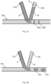
- Fig. 2A shows a schematic view of a first sample injection channel (114) and a second sample injection channel (116) connected to the target channel (102).
- Fig. 2A shows injection of a first sample species (A) and a second sample species (B) without using a hydrodynamic resistor (not shown).
- a first sample injection channel (114) is connected with its sample injection channel junction end to the target channel (102), e.g., of a microfluidic chip (124).
- a second sample injection channel (116) is connected with its sample injection channel junction end to the target channel (102), e.g., of the microfluidic chip (124).
- the first sample injection channel (114) is an injecting channel, i.e. currently injecting the first sample species (A) in the target channel (102), e.g. during a first time
- the second sample injection channel (116) is a non-injecting channel, i.e. currently not injecting the second sample species (B), e.g. during the first time.
- This can be seen in the resulting microcompartments (202) of Fig. 2A , which, as an example, only include sample species (A).
- the first sample species (A) does not only end up in the target channel (102), e.g. to form microcompartments (202) therein, but also in the second sample injection channel (116), which is intended for injection of the second sample species (B). Accordingly, this backflow results in significant cross-contamination, e.g. of the created microcompartments (202), particularly, when the second sample injection channel (116) becomes an injecting channel, e.g. during a second time being different from the first time, i.e. when it is used for injecting the second sample species (B), since remaining traces of the first sample species (A) will be co-injected therewith.
- such a backflow and/or cross contamination may not only flow into a (neighboring) sample injection channel which is currently non-injecting, e.g., the second sample injection channel (116), but even also into the second sample species reservoir (106).
- a sample injection channel which is currently non-injecting
- the second sample injection channel e.g., the second sample injection channel (116)
- the second sample species reservoir 106
- the generated microcompartments (202) are not equally sized and have a non-uniform shape, e.g. the microcompartments (202) are bulky, deformed or distorted, which is caused by pressure differences related to the backflow seen in Fig. 2A and/or pressure/flow rate differences related to overshooting or overregulating due to sudden flow rate changes.
- a combinatorial microcompartment s. for example combinatorial microcompartment (200A; 200B) of Fig. 2C )
- this may also result in a cross-contamination combinatorial microcompartment, i.e. where the two species are mixed.
- Fig. 2B shows a schematic view of a first sample injection channel (114) and a second sample injection channel (116) which are valvelessly connected to the target channel (102) as in Fig. 2A.
- Fig. 2B shows injecting the first sample species (A) and the second sample species (B) using a hydrodynamic resistor according to embodiments of the present disclosure (not shown).
- the first sample injection channel (114) is valvelessly connected with its sample injection channel junction end to the target channel (102), e.g., of a microfluidic chip (124).
- the second sample injection channel (116) is valvelessly connected with its sample injection channel junction end to the target channel (102), e.g., of the microfluidic chip (124).
- the sample injection channel junction end (114B; 116B) of the first sample injection channel (114) and/or the second sample injection channel (116) include at least one hydrodynamic resistor (not shown).
- the first sample injection channel (114) is an injecting channel, i.e. currently injecting the first sample species (A) in the target channel (102), e.g. during a first time
- the second sample injection channel (116) is a non-injecting channel, i.e. currently not injecting the second sample species (B), e.g. during the first time.
- This can be seen in the resulting microcompartments (202) of Fig. 2B , which, as an example, only include sample species (A).
- the first sample species (A) does not end up in the second sample injection channel (116), which is intended for injection of the second sample species (B).
- a non-injection pressure P ni is maintained on the second sample species reservoir (106) of the sample injection channel (116), which is currently non-injecting, e.g. during the first time and the use of hydrodynamic resistor in connection with the valveless connection.
- P ni is maintained on the second sample species reservoir (106) of the sample injection channel (116), which is currently non-injecting, e.g. during the first time and the use of hydrodynamic resistor in connection with the valveless connection.
- backflow of sample species (A) in the second sample injection channel (116) is avoided. This reduces or prevents cross-contamination, particularly, when the second sample injection channel (116) becomes an injecting channel, e.g. during a second time being different from the first time, i.e.
- the generated microcompartments (202) of Fig. 2B are more equally sized and have a more uniform shape, e.g. continuous, which is a result of backflow being reduced or avoided, i.e. due to maintaining a non-injection pressure P ni on the sample species reservoir (106) of non-injecting second sample injection channel (116) in combination with using a hydrodynamic resistor.
- FIGs. 2A and 2B depict generation of a microcompartment (202), these embodiments are not so limited, i.e. the first and second sample injection channels (114; 116) may likewise be used for generation of a combinatorial microcompartment (200A; 200B) as shown in Fig. 2C , e.g. including mixtures of the first sample species (A) and the second sample species (B).
- Fig. 2C shows a schematic view of different microcompartments created within a carrier phase of a target channel (102) according to embodiments of the present disclosure, e.g. generated maintaining a non-injection pressure P ni on the sample species reservoir (106) of non-inj ecting second sample injection channel (116) and using at least one hydrodynamic resistor according to embodiments of the present disclosure.
- Fig. 2C shows two combinatorial microcompartments (200A; 200B) comprising at least two sample species, e.g. of a different composition and a microcompartment (202) comprising only one sample species.
- the first combinatorial microcompartment (200A) includes the first sample species (A) and the second sample species (B).
- the second combinatorial microcompartment (200B) includes a plurality of sample species (A-D), including the first sample species (A), the second sample species (B), a third second sample species (C) and a fourth second sample species (D).
- the sample species (A-D) may be chemically and/or biologically distinct.
- the number of sample species in a combinatorial microcompartment (200A) is not limited as long as there are at least two sample species included.
- the two combinatorial microcompartments (200A; 200B) and the microcompartment (202) of Fig. 2C have been produced, e.g., by the microfluidic device (100) shown in Fig. 1 and therefore have a uniform shape and/or are equally sized.
- the combinatorial microcompartments (200A; 200B) no cross-contamination between the different sample species (A-D) is present within the created combinatorial microcompartments (200A; 200B). Rather, the sample species (A-D) are clearly separated, divided or distinct from each other.
- Fig. 3 shows a flow diagram of a method (300) according to embodiments described herein. As shown in Fig. 3 , the method (300) is for providing one or more combinatorial microcompartments (200A; 200B) each comprising at least two sample species (A; B).
- the method (300) is for providing one or more combinatorial microcompartments (200A; 200B) each comprising at least two sample species (A; B).
- the method comprises injecting (302), into a continuous flow of a carrier phase of a target channel (102), a first sample species (A) from a first sample species reservoir (104) via a first sample injection channel (114) to create a microcompartment (202), and injecting (304), into the created microcompartment (202), at least one second sample species (B) from a second sample species reservoir (106) via a second sample injection channel (116) to create a combinatorial microcompartment (200).
- the method further comprises providing (306) a resistance within the first in the first injection channel (114) and/or the second injection channel (116) using at least one hydrodynamic resistor.
- the resistance may be a hydrodynamic resistance.
- the resistance may be provided during i) injecting (302) of the first sample species (A) and/or injecting (304) the second sample species (B) and ii) non-injecting of the first sample species (A) and/or non-injecting the second sample species (B)
- the first sample species (A) and the second sample species (B) may be injected by applying an injection pressure P i to the respective first species reservoir (104) and the second species reservoir (106), while a non-injection pressure P ni being lower than the injection pressure P i may be maintained on each sample species reservoir (104; 106) of each non-injecting sample injection channel (114; 116).
- the method may optionally include the step of repeating (306) of the steps (302; 304) to create another combinatorial microcompartment in order to create a sequence of combinatorial microcompartments within the carrier phase of a target channel (102).
- injecting the second sample species (B) may occur sequentially or concomitantly to injecting the first sample species (A). That is, during a first time, both the first sample species (A) and the second sample species (B) may be injected. Alternatively, the first sample species (A) may be injected at a first time and the second sample species (B) may be injected at a second time being different than the first time, or vice versa.
- the first sample species (A) does not end up in the second sample injection channel (116), which is intended for injection of the second sample species (B).
- the non-inj ection pressure P ni is maintained on the second sample reservoir and a resistance within the first injection channel (114) and/or the second injection channel (116) using at least one hydrodynamic resistor is provided.
- "backflow" of sample species (A) from the first sample injection channel (114) into the second sample injection channel (116) is reduced or avoided.
- pressure and/or flow rate differences related to overshooting or overregulating due to sudden flow rate changes can be balanced out, reduced, prevented or minimized.
- this avoids cross-contamination, e.g., when the second sample injection channel (116) is used for injecting the second sample species (B), as no remaining traces of the first sample species (A) will be co-injected therewith.
- Fig. 4A shows a pressure profile during sample injection without maintaining a non-injection pressure P ni on the non-injecting sample species reservoir.
- the x-axis of Fig. 4A shows a time in seconds, while the y-axis of Fig. 4A shows a pressure in mbar.
- a (combinatorial) microcompartment created therefrom may be less uniform and not equally sized (s. for example the microcompartments created in Fig. 2A ). This may also cause overshooting or overregulating due to sudden flow rate changes.
- Fig. 4B shows a pressure profile during sample injection maintaining a non-injection pressure P ni and using a hydrodynamic resistor according to embodiments of the present disclosure.
- the x-axis of Fig. 4B shows a time in seconds, while the y-axis of Fig. 4B shows a pressure in mbar.
- the pressure profiles of pressure peaks are rather uniform when compared to the measurements shown in Fig. 4A , resulting in the formation of equally sized and non-contaminated (combinatorial) microcompartments (s. for example Fig. 2B or Fig. 2C ). With respect to microcompartments (s. for example Fig. 2C ), this may also result in reduction or prevention of cross-contamination as well as to a reduction in overshooting or overregulating due to sudden flow rate changes.
- the linear increase in pressure is due to increasing back pressure in, e.g., the target channel (102) (s. Fig. 1 ) with increasing sample numbers.
- Fig. 5A shows a flow rate profile during sample injection without maintaining a non-injection pressure P ni .
- the x-axis of Fig. 5A shows a time in seconds, while the y-axis of Fig. 5A shows a flow rate in ⁇ l/min.
- the flow rates on the y-axis include positive values and negative flow rate values.
- the second sample species B which corresponds to sample 2 in the diagram of Fig. 5A
- a negative flow rate is observed.
- Such a negative flow rate indicates undesired back flow and cross-contamination between neighboring sample injection channels as mentioned above (s. for example Fig. 2A ).
- Fig. 5B shows a flow rate profile maintaining a non-injection pressure P ni and using a hydrodynamic according to embodiments of the present disclosure.
- the x-axis of Fig. 5A shows a time in seconds, while the y-axis of Fig. 5A shows a flow rate in ⁇ l/min.
- Fig. 5C shows another flow rate profile of a microfluidic chip maintaining a non-injection pressure P ni , but without using hydrodynamic resistors.
- the x-axis of Fig. 5C shows a time in seconds, while the y-axis of Fig. 5C shows a flow rate in ⁇ l/min.
- Fig. 5C further shows how the flow rate changes over time when three samples (Sample 1-3) are being injected.
- a sudden flow rate change occurs, e.g. overshooting, where the flow rate briefly exceeds a desired or target flow rate before settling back or returning to the target flow rate. That is, in Fig. 5C , the overshoot peaks represent instances where the flow rate exceeds the desired flow rate.
- a microcompartment was generated using samples of different fluorophores for injection, such as a green, an orange and a blue fluorescent dye.
- a fluorescent dye is a type of molecule that absorbs light at one wavelength and re-emits it at a longer wavelength, producing a visible fluorescence in different colors, e.g. depending on the fluorophore used. These dyes may be used to visualize specific structures within a microcompartment or track the movement of molecules within cells.
- the fluorescence dyes can be used to detect cross-contamination within a (combinatorial) microcompartment. Fluorescent dyes can be excited with a specific light source to produce a bright and easily detectable fluorescence signal, which may be indicative of cross-contamination.
- Fig. 6A shows a measurement of cross contamination in a combinatorial microcompartment comprising at least two sample species (A; B) created without maintaining a non-injection pressure P ni .
- Fig. 6A cross-contamination is monitored while injecting a green, an orange and a blue fluorescent dye in a microcompartment to create a combinatorial microcompartment (200A; 200B), i.e. comprising at least two sample species.
- the combinatorial microcompartment is created without maintaining a non-injection pressure P ni .
- the x-axis of Fig. 6A shows a time in seconds, while the y-axis of Fig. 6A shows a fluorescence intensity in arbitrary units, e.g. a unit of measurement that is not based on any internationally recognized standard, but rather on an arbitrary scale chosen by the experimenter including values ranging from 0 to 6 A.U.
- Z-factors may be used.
- a Z-factor may be a statistical measure used to evaluate the quality of an assay or, in this case, a sample species within a combinatorial microcompartment.
- the Z-factor may therefore correspond to a measure indicating cross contamination between at least two species in the combinatorial microcompartment, as cross-contamination alters the fluorescence readings and, e.g. decreases the Z-factor.
- Z-factors of 0.5 to 1.0 are considered good (e.g. having no or reduced cross-contamination), while values lower than 0.5 or even negative Z-factor values indicate cross-contamination between species within the combinatorial microcompartments.
- the fluorescence response is rather non-uniform indicating cross-contamination between the fluorescent dyes.
- the Z-factor measured for the green fluorescence dye was -4.03
- the Z-factor measured for the orange fluorescence dye was -0.726
- the Z-factor measured for the blue fluorescence dye was - 1.462.
- Fig. 6B cross contamination is monitored while injecting a green, an orange and a blue fluorescent dye in a microcompartment to create a combinatorial microcompartment (200A; 200B), i.e. comprising at least two sample species.
- the combinatorial microcompartment was created maintaining a non-injection pressure P ni and using a hydrodynamic resistor according to embodiments of the present disclosure.
- the x-axis of Fig. 6B shows a time in seconds
- the y-axis of Fig. 6B shows a fluorescence intensity in arbitrary units, e.g. a unit of measurement that is not based on any internationally recognized standard, but rather on an arbitrary scale chosen by the experimenter including values from 0 to 1 AU.
- the fluorescence response is rather uniform indicating significantly reduced cross-contamination between the fluorescent dyes when compared to measurements shown in Fig. 6A .
- the Z-factor measured for the green fluorescence dye was 0.612
- the Z-factor measured for the orange fluorescence dye was 0.74
- the Z-factor measured for the blue fluorescence dye was 0.714.
- the Z-factors measured in a combinatorial microcompartment created by maintaining a non-injection pressure P ni and using a hydrodynamic resistor according to embodiments of the present disclosure are not only positive values, but also within the range of 0.5-1.0 indicating that cross contamination within the combinatorial microcompartments is significantly reduced or avoided, when compared to the measurement shown in Fig. 6A .
- the combinatorial microcompartment measured in Fig. 6B was created using the microfluidic device (100) shown in Fig. 1 and/or the method shown in Fig. 3 .
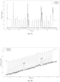
- Fig. 7A shows flow rate data (i.e. backflow and overshoot) recorded with a microfluidic chip without using a hydrodynamic resistor while Fig. 7B shows flow rate data (i.e. backflow and overshoot) recorded with a microfluidic chip using a hydrodynamic resistor both while maintaining a non-injection pressure P ni according to embodiments of the present disclosure.
Landscapes
- Chemical & Material Sciences (AREA)
- Dispersion Chemistry (AREA)
- Health & Medical Sciences (AREA)
- Analytical Chemistry (AREA)
- General Health & Medical Sciences (AREA)
- Hematology (AREA)
- Clinical Laboratory Science (AREA)
- Chemical Kinetics & Catalysis (AREA)
- Physical Or Chemical Processes And Apparatus (AREA)
- Automatic Analysis And Handling Materials Therefor (AREA)
- Apparatus Associated With Microorganisms And Enzymes (AREA)
Abstract
The present disclosure provides a method and a microfluidic device for producing one or more combinatorial microcompartment comprising at least two sample species within a carrier phase, the microfluidic device comprising a target channel, a first sample species reservoir comprising a first sample species and at least a second sample species reservoir comprising a second sample species, a first sample injection channel comprising a sample injection channel reservoir end connected to the first sample species reservoir and a sample injection channel junction end connected to the target channel, and at least a second sample injection channel comprising a sample injection channel reservoir end connected to the second sample species reservoir and a sample injection channel junction end connected to the target channel; wherein the sample injection channel junction end of the first sample injection channel and/or the second sample injection channel are valvelessly connected to the target channel and comprise at least one hydrodynamic resistor.
Description
- Embodiments described herein relate to a device, particularly a microfluidic device, and a method for producing one or more combinatorial microcompartment(s) comprising at least two sample species within a carrier phase.
- A problem encountered in microfluidic devices is related to microfluidic backflow. Microfluidic backflow may refer to an unintended flow of liquid, fluid or aqueous samples from one channel or one compartment in the microfluidic device into another channel or another compartment. Backflow therefore results in cross-contamination between, e.g., neighboring channels, microcompartments and/or combinatorial microcompartments which can be a significant problem in microfluidic experiments and assays because liquids, fluids or aqueous samples that should be kept separate can (e.g. unintentionally) mix or disrupt the intended flow of fluids in the microfluidic device.
- As mentioned, microfluidic backflow may occur between channels and/or microcompartments. Several factors may contribute to microfluidic backflows in channels, for example pressure differences: if a pressure in one channel is greater than a pressure in another channel, liquid, fluid or aqueous samples can flow from the higher pressure channel into the lower pressure channel resulting in backflow; hydrodynamic flow: when liquid, fluid or aqueous samples are flowing in one channel, they can create a flow that draws liquid, fluid or aqueous samples from other channels into the flowing channel; capillary forces: capillary forces can cause liquid, fluid or aqueous samples to be drawn into adjacent or neighboring channels; and/or incomplete sealing: if seals between channels are not properly designed or are not tightly sealed, liquid, fluid or aqueous samples can leak from one channel into another.
- Microfluidic backflow in microcompartments may be caused, for example, by: pressure differences across the micro-channels poor channel design leading to channel blockages; viscous drag forces of the liquid, fluid or the aqueous sample; flow rate mismatches between the inlets and outlet; electrostatic interactions between the liquid, fluid or the aqueous sample and channel wall and/or changes in temperature and viscosity of the liquid, fluid or the aqueous sample.
- Typically, the use of flow-controlling and/or switching on-chip valves, such as pneumatic valves (e.g. Quake valves) or Braille valves, can help to prevent or reduce backflow by enabling precise control over the flow of fluids in a microfluidic device.
- Valves can be used to generate different aqueous samples. The aqueous samples can be mixed and/or compartmentalized on a microfluidic chip in connection with a co-injection of a carrier phase, such as water or oil, by utilizing the valve's ability to selectively route and control fluid flow in microfluidic channels. To this end, valves can be used to direct the flow of fluids into specific microcompartments within a microfluidic chip, allowing the creation of multiple isolated compartments with, e.g., different chemical or biological environments. These aqueous microcompartments can be used for a variety of purposes, such as conducting chemical reactions, encapsulating cells or other biological materials, or for high throughput screening applications, e.g. allowing for the creation of multiple, isolated environments for screening reactions or assays.
- However, there are several limitations when using Valves to generate different aqueous samples or combinatorial mixtures, including i) complexity, e.g. Valves can be difficult to fabricate and to integrate into microfluidic devices due to their small size and intricate design; ii) maintenance, e.g. valves can be prone to clogging, leakage or wear over time, which can require regular maintenance and cleaning to ensure proper function; iii) limited number of channels; e.g. the number of channels that can be controlled using a single valve is limited, which can limit the number of screening assays that can be performed in parallel; iv) accuracy, e.g. the requirement for very accurate alignment of the valve e.g. on an external actuator (e.g. aligning a Braille valve on a Braille display); and/or v) limited scalability, e.g. it can be difficult to scale up the number of valves for high-throughput screening applications due to the complex fabrication process and the need for precise alignment of the valves within the microfluidic device. However, usage of valves for generating combinatorial mixtures additionally requires prevention of undesired microfluidic backflow. Furthermore, flexible materials, such as a PDMS (Polydimethylsiloxane) material which is a silicone-based polymer material that is commonly used in microfluidics due to its transparency, low surface energy, and biocompatibility, are required for correct functioning of the valves, even though the same are difficult to produce in a standardized scalable fashion.
-
US Patent No. 5,726,404 is titled "Valveless Liquid Microswitch" describes a valveless liquid microswitch that can be used for controlling fluid flow in microfluidic devices. The microswitch includes a chamber filled with a liquid that can be actuated by a piezoelectric element or other suitable actuator. - Accordingly, it is beneficial to provide an improved microfluidic device and method to prevent, reduce and/or counteract microfluidic backflow between channels and/or microcompartments while minimizing or eliminating the limitations associated with the usage of valves.
- The subject-matter provided by the present invention is defined in the independent claims, while preferred embodiments of the present invention are defined in the dependent claims.
- The invention in its most generic embodiment pertains to a method and device for combining two or more different sample fluids (or liquids) and a target channel fluid within a microfluidic device by temporary injection of at least one of the at least two sample fluids from one of at least two sample injection channels into a target channel comprising the target channel fluid at a sample injection junction (which shall be understood as a channel junction between the target channel and the one of the at least two sample injection channels). The target channel preferably comprises a continuous flow of the target channel fluid which is provided via a target channel fluid reservoir. The method and device of the invention then provides that the at least one sample injection fluid to be injected is provided into the sample injection channel via a pressurized sample injection fluid reservoir, preferably, wherein an injection pressure Pi is applied during injection phase and when non-injection pressure Pni is applied during the non-injecting phase, and wherein the at least two sample injection channels are each valvlessly connected to a sample injection fluid reservoir via at least one hydrodynamic resistor. The invention thus provides sample injection channels that are supplied by continuously pressurized sample injection reservoirs both during injection phases and non-injection phases in combination with hydrodynamic resistors arranged between the sample injection junction and the sample injection reservoir. Such combination is surprisingly effective in avoiding injection channel backflow compared to prior art devices and methods. The invention will be described in the following in detail with reference to specifically preferred embodiments.
- In the following detailed description of the invention, the target channel fluid is also referred to as a carrier fluid or carrier phase, wherein the injection channel fluid may be referred to as a sample species or fluid.
- In light of the above, a microfluidic device as well as a method for combining at least two fluids in a microfluidic device is provided. Such inventive method for combining fluids is particular useful for producing combinatorial microcompartments. Hence, in view of the above, the invention further provides a microfluidic device as well as a method for producing one or more combinatorial microcompartment(s) comprising at least two sample species within a carrier phase is provided.
- According to an embodiment, a microfluidic device comprising at least two sample species within a carrier phase is provided. The microfluidic device comprising a target channel, a first sample species reservoir comprising a first sample species and at least a second sample species reservoir comprising a second sample species. The microfluidic device comprising a first sample injection channel comprising a sample injection channel reservoir end connected to the first sample species reservoir and a sample injection channel junction end connected to the target channel, and at least a second sample injection channel comprising a sample injection channel reservoir end connected to the second sample species reservoir and a sample injection channel junction end connected to the target channel. The sample injection channel junction end of the first sample injection channel and/or the second sample injection channel are valvelessly connected to the target channel and comprise at least one hydrodynamic resistor. In preferred embodiments of the invention, sample species reservoirs comprised in the microfluidic device of the invention are capable of being pressurized during injection and non-injection of sample liquid. In one preferred embodiment the microfluidic device is for producing one or more combinatorial microcompartments.
- According to an embodiment, a method for operating a microfluidic device is provided, the method comprising: injecting, into a continuous flow of a carrier phase of a target channel (wherein preferably the continuous flow of the carrier phase is injected into the target channel from a carrier phase reservoir), a first sample species from a first sample species reservoir via a first sample injection channel. The method further comprises injecting into the continuous flow of a carrier phase of the target channel at least one second sample species from a second sample species reservoir via a second sample injection channel, wherein (i) the first sample species and the second sample species are injected by applying an injection pressure Pi to the respective first species reservoir and the second species reservoir, while a non-injection pressure Pni being lower than the injection pressure Pi is being maintained on each sample species reservoir of each non-injecting sample injection channel, and/or (ii) a resistance within the first injection channel and/or the second injection channel using at least one hydrodynamic resistor is provided.
- According to another embodiment, a method for providing one or more combinatorial microcompartment(s) comprising at least two sample species is provided. The method comprises: injecting, into a continuous flow of a carrier phase of a target channel, a first sample species from a first sample species reservoir via a first sample injection channel to create a microcompartment. The method further comprises injecting, into the created microcompartment, at least one second sample species from a second sample species reservoir via a second sample injection channel to create a combinatorial microcompartment, wherein (i) the first sample species and the second sample species are injected by applying an injection pressure Pi to the respective first species reservoir and the second species reservoir, while a non-injection pressure Pni being lower than the injection pressure Pi is being maintained on each sample species reservoir of each non-injecting sample injection channel, and/or (ii) a resistance within the first injection channel and/or the second injection channel using at least one hydrodynamic resistor is provided.
- According to an embodiment, a microfluidic chip is provided, including one or more combinatorial microcompartment(s), comprising at least two sample species produced by injecting, into a continuous flow of a carrier phase of a target channel, a first sample species from a first sample species reservoir via a first sample injection channel to create a microcompartment, and injecting, into the created microcompartment, at least one second sample species from a second sample species reservoir via a second sample injection channel to create a combinatorial microcompartment, wherein (i) the first sample species and the second sample species are injected by applying an injection pressure Pi to the respective first species reservoir and the second species reservoir, while a non-injection pressure Pni being lower than the injection pressure Pi is being maintained on each sample species reservoir of each non-injecting sample injection channel, and/or (ii) a resistance within the first injection channel and/or the second injection channel using at least one hydrodynamic resistor is provided.
- Further aspects, advantages, and features are apparent from the dependent claims, the description, and the accompanying drawings.
- So that the manner in which the above recited features of the present disclosure can be understood in detail, a more particular description of the disclosure, briefly summarized above, may be had by reference to embodiments. The accompanying drawings relate to embodiments of the disclosure and are described in the following:
- FIG. 1
- shows a schematic view of a microfluidic device for producing a combinatorial microcompartment according to embodiments described herein;
- FIG. 2A
- shows a schematic view of injecting a first sample species and a second sample species and the occurrence of undesired back-flow due to a lack of combining (i) maintenance of a non-injection pressure on sample species reservoirs of non-injecting sample injection channels with (ii) hydrodynamic resistors;
- FIG. 2B
- shows a schematic view of avoiding undesired backflow when injecting a first sample species and a second sample species while maintaining a non-injection pressure on sample species reservoirs of non-injecting sample injections channels while using a hydrodynamic resistor according to embodiments of the present disclosure;
- FIG. 2C
- shows a schematic view of different microcompartments and combinatorial microcompartments created in a carrier phase of a target channel according to embodiments of the present disclosure;
- FIG. 3
- shows a flow diagram of a method according to embodiments described herein;
- FIG. 4A
- shows a pressure profile during sample injection without combining maintaining a non-injection pressure on sample species reservoirs of non-injecting sample injections channels with using a hydrodynamic resistor;
- FIG. 4B
- shows a pressure profile during sample injection while maintaining a non-injection pressure on sample species reservoirs of non-injecting sample injections channels and using a hydrodynamic resistor according to embodiments of the present disclosure;
- FIG. 5A
- shows a flow rate profile during sample injection without combining maintaining a non-injection pressure on sample species reservoirs of non-injecting sample injections channels with using a hydrodynamic resistor;
- FIG. 5B
- shows a flow rate profile during sample injection while maintaining a non-injection pressure on sample species reservoirs of non-injecting sample injections channels and using a hydrodynamic resistor according to embodiments of the present disclosure;
- FIG. 5C
- shows another flow rate profile during sample injection while maintaining a non-injection pressure on sample species reservoirs of non-injecting sample injections channels without using hydrodynamic resistors;
- FIG. 6A
- shows a measurement of cross contamination in a microcompartment created with a microfluidic device without maintaining a non-injection pressure on sample species reservoirs of non-injecting sample injections channels but using a hydrodynamic resistor;
- FIG. 6B
- shows a measurement of cross contamination in a microcompartment created maintaining a non-inj ection pressure on sample species reservoirs of non-injecting sample injections channels but using a hydrodynamic resistor according to embodiments of the present disclosure;
- FIG. 6C
- shows a measurement of cross contamination in a microcompartment created while maintaining a non-injection pressure on sample species reservoirs of non-injecting sample injections channels but on a chip without a hydrodynamic resistor;
- FIG. 7A
- shows flow rate data in ul/min (i.e. backflow and/or overshoot) recorded within a microfluidic chip without using a hydrodynamic resistor;
- FIG. 7B
- shows flow rate data in ul/min (i.e. backflow and/or overshoot) recorded within a microfluidic chip using a hydrodynamic resistor in combination with maintaining a non-injection pressure on sample species reservoirs of non-injecting sample injections channels in accordance with the preferred embodiments of the invention.
- FIG. 8A
- shows a microfluidic chip setup including hydrodynamic resistors in accordance with the invention, such a chip used for
Figs. 4 to 6B ; - FIG. 8B
- shows a microfluidic chip setup without hydrodynamic resistors such as a chip used for
Fig. 5C ,6C, and 7A . - Reference will now be made in detail to the various embodiments of the disclosure, one or more examples of which are illustrated in the figures. The drawings are schematic drawings which are not drawn to scale. Some elements in the drawings may have dimensions which are exaggerated for the purpose of highlighting aspects of the present disclosure and/or for the sake of clarity of presentation. To facilitate understanding, identical reference numerals have been used, where possible, to designate identical elements that are common to the figures. It is contemplated that elements and features of one embodiment may be beneficially incorporated in other embodiments without further recitation. Generally, only the differences with respect to individual embodiments are described.
- Each example is provided by way of explanation of the disclosure and is not meant as a limitation of the disclosure. Further, features illustrated or described as part of one embodiment can be used on or in conjunction with other embodiments to yield yet a further embodiment. It is intended that the description includes such modifications and variations.
- Embodiments described herein relate to a microfluidic device for producing one or more combinatorial microcompartment(s).
- A "microfluidic device" may be understood as a miniaturized system for controlling, directing and/or manipulating amounts of fluid, liquid or aqueous samples, e.g. within a microliter scale or a nanoliter scale. These devices may be made by fabricating channels and compartments in a substrate material, such as glass, plastic, or silicone, to create a controlled environment for (micro-) fluidic processes. Microfluidic devices can be used to perform a wide range of fluidic operations, such as mixing, pumping, separation, and reaction, and they may be used in a variety of applications, including chemical analysis, cell culture, drug discovery, and medical diagnostics. The small size and precise control of microfluidic devices allow for efficient and cost-effective experimentation, as well as the ability to perform experiments and assays that would not be possible using traditional, larger-scale fluidic systems.
- A "microcompartment" may be understood as a liquid, fluidic or aqueous sample which is dispersed within a continuous phase, e.g. a surrounding carrier phase or carrier fluid such as oil or water. In this respect, a microcompartment may be viewed as a miniaturized reaction or assay vessel. The fluid, liquid or the aqueous sample inside of a microcompartment is immiscible with the fluid or liquid of the carrier phase.
- The microcompartments can be in the form of surfactant droplets, e.g. emulsions with volumes in the pico-liter range. A surfactant droplet may be a, e.g., spherical droplet of a surfactant solution surrounded by a continuous phase, e.g. oil or water. Surfactants are surfaceactive compounds that can reduce the surface tension between two immiscible liquids, allowing, e.g., the formation of stable droplets in the continuous phase. In a surfactant droplet, the surfactant molecules are adsorbed at the interface between the droplet and the continuous phase, creating a stabilized interface that prevents the droplet, and also the material inside, from merging with the continuous phase.
- The microcompartments can also be (microfluidic) plugs, e.g. with volumes in the nanoliter range, that completely fill a target channel or tubing. The plugs may be separated by the carrier phase or carrier fluid, e.g. oil or water. In this case, there is no need for stabilizing surfactants.
- The microcompartments can also be flow segments, e.g. a portion or section within the microfluidic channel or tubing, where the fluid flow has a specific and distinct behavior, e.g. exceeding microliter volumes.
- A "combinatorial microcompartment" may be understood as a microcompartment comprising at least two sample species or substances, e.g. sample species (A) and sample species (B), which may be chemically and/or biologically distinct. As such, a combinatorial microcompartment may be referred to as including a mixture of different species compartmentalized within the carrier phase.
- Possible sample species include molecule drugs or compounds, proteins or enzymes, nucleic acids (DNA, RNA), cells or microorganisms, such as prokaryotic or eukaryotic cells, microscopic tissue samples, particles or nanoparticles and/or biomolecules such as sugars, lipids or hormones.
- Chemically and/or biologically distinct may refer to substances, entities or materials that have different chemical/biological properties and compositions. This may be understood in that they may differ in their molecular structure, chemical behavior, and/or biological activity. The distinction can be based on differences in the composition of individual molecules, the type and arrangement of atoms, the presence or absence of specific functional groups, or differences in biological activity. For example, chemically distinct entities include different bioactive substances such as drugs causing a specific cellular response. Biologically distinct entities include different types of cells, cells coming from different donors, cell libraries expressing different variants of a given protein and tissue slices
- A microfluidic device according to embodiments discussed herein may include a first sample species reservoir comprising a first sample species (A) and at least a second sample species reservoir comprising a second sample species (B).
- A "reservoir" or a "sample species reservoir" may be understood as a storage facility or container used to store, contain or hold volumes of a particular sample species, e.g. containing an aqueous sample, fluid or liquid. The applied pressure on the reservoir may also regulate a flow or outflow of these sample species. Typical volumes of such sample reservoirs are in the range of a few picoliters to a few milliliters, particularly a few nanoliters to a few microliters, more particularly a few microliters to a few milliliters or also even higher/lower.
- A "sample species" stored within a sample species reservoir may be understood as a fluid, liquid or aqueous sample comprising, e.g. water, which may further include dissolved or suspended substances, e.g. of a particular chemical/biological species, e.g. a substance or material having a chemically and/or biological distinct property, characteristic, compound and/or composition, e.g. (A), (B), (C) etc. The sample species may also comprise a carrier phase, e.g. oil and water. The sample, sample species and/or the carrier phase may be stored in the form of a fluid or liquid, wherein these terms may be used interchangeably herein. Carrier phase fluids or -liquids are usually selected from oils, but in certain applications of the invention may include aqueous sample liquids.
- A "target channel" in context of the present invention shall be understood as the channel into which two, three or more fluids are combined, and wherein the combined fluids are further transported, for example to any assay area, detection area, storage reservoir, or any other means for which the combination of fluids is performed. The term should be understood as a channel or tube, e.g. of a microfluidic chip, into which samples according to the invention are combined. The target channel may be configured for holding, guiding or supporting the target channel fluid such as a carrier phase. The "carrier phase", e.g. within the target channel, may be regarded as a fluid or liquid that flows through the chip, e.g. continuously, in order to move or transport the sample through the chip. The carrier phase can be a liquid, such as water or oil and its properties, such as viscosity, surface tension, and pH, can be adjusted to optimize the transport of the samples.
- The term "injection channel" shall refer to the one or more channels from which fluids are injected into the target channel to combine the one or more fluids in accordance with the invention. The injection channel in some instances of the invention may also be referred to as a sample injection channel. The term "sample" shall in this case refer to the one or more fluids to be injected into the target channel.
- Although it is mentioned that the first sample species reservoir comprises a first sample species (A) that may be different from a second sample species (B) comprised in the second sample species reservoir, it may also be possible to have both sample species reservoirs to comprise the same sample species, e.g. (A) or (B).
- The microfluidic device may comprise a first sample injection channel and a second sample injection channel. A "sample injection channel" may be understood as a (fluidic) channel, pathway or tubing which is used to transport or deliver a fluid, liquid or aqueous ample, for example a particular sample species to, e.g., the target channel. The carrier phase may also be injected using one or more sample injection channels.
- Sample injection channels may be made from glass, silicone or plastics. The diameter of a sample injection channel ranges from a few tens of micrometers to several millimeters. For example, in a microfluidic device used for high-throughput screening applications, the sample injection channel may have a diameter of several micrometers.
- However, larger diameters may be beneficial. For example, when working with cells, larger channels diameters may be used to avoid clogging of the channels, e.g. by allowing the cells to pass through without getting trapped or stuck. The first sample injection channel comprises a sample injection channel reservoir end connected to the first sample species reservoir and a sample injection channel junction end connected to the target channel, and the second sample injection channel comprises a sample injection channel reservoir end connected to the second sample species reservoir and a sample injection channel junction end connected to the target channel.
- At the injection channel "reservoir end", the sample injection channel may be connected valveless to the sample species reservoir. However, the sample species reservoir may be pressurized and the pressure may be released by "external valves", e.g. valves connected to a pressure source (s. below).
- In general, at least two sample injection channels connected to a respective first sample species reservoir comprising a first sample species and second sample species reservoir comprising a second sample species may be used to generate the combinatorial microcompartment recited herein. For creating a microcompartment, also only one sample injection channel may be sufficient.
- The sample injection channel junction end of the first sample injection channel and/or the second sample injection channel are valvelessly connected to the target channel and comprise a hydrodynamic resistor.
- The sample injection channel "junction end" may define an end of the sample injection channel where the same encounters, intersects, merges or is connected to the target channel. A "valveless" connection may be understood as a connection that does not comprise or use a valve, e.g. for controlling the flow of fluids. In a microfluidic device with a valveless connection between a sample injection channel and a carrier phase, the sample may be introduced into the carrier phase through a small opening or constriction at the sample injection channel junction end. The pressure difference between the sample and the carrier phase, e.g. along with the geometry of the channel and the fluidic resistance of the channels, may determine the flow rate and mixing of the aqueous sample and carrier phase. Valveless connections may have improved reliability, lower cost, and reduced complexity. They can also be easier to fabricate and to maintain compared to other devices that use valves.
- A "hydrodynamic resistor" may be understood as a device that provides a hydrodynamic resistance to fluid flowing in the sample injection channel in order to control, regulate the flow of fluids in a microfluidic system. A pressure drop may be created across the resistor, which resists the flow of fluid and regulates the flow rate of the fluid. Hydrodynamic resistors may be implemented as narrow channels, constrictions or constricted regions, or regions of increased fluidic resistance within a microfluidic device creating a pressure drop or pressure increments, e.g. an amount by which pressure is increased or decreased during a time period, which generates hydrodynamic/flow resistance.
- Hydrodynamic resistors may be implemented as a narrow channel, e.g. having a smaller diameter. This is because the resistance offered by the channel is roughly inversely proportional to the fourth power of the diameter of the channel. In other words, if the diameter of the channel is reduced by a factor of 2, the resistance of the channel increases by a factor of 16. As a result, the smaller the diameter of the channel, the higher the resistance, and the more effective the channel is at regulating pressure. Therefore, hydrodynamic resistors may be implemented as channels of small diameter, as this offers a higher resistance and better pressure regulation than shorter, wider channels.
- Hydrodynamic resistors may serve as a pressure regulator or pressure controller which contributes in preventing backflow and ensures stable pressure in a microfluidic device. For example, when pressure is applied to a reservoir in a microfluidic device, a pressure pulse may be created that can lead to rapid pressure changes due to sudden flow rate changes, e.g. overshooting and overregulation of pressures in sample injection channels. This may result in undesired flow into one or another direction and disruption of the system. By using a hydrodynamic resistor, the pressure pulse may be attenuated or damped and a response time between applying a certain pressure and having an effect at the droplet generation point, e.g. where the droplet is produced, is increased, allowing for more stable and precise pressure regulation. This is also important for channels which are non-injecting, as the system may heavily overregulate without hydrodynamic resistors, causing pressure pulses and undesired flow in either direction. Thus, the hydrodynamic resistor may maintain stability and precision in a microfluidic device by regulating or controlling pressure and preventing backflow.
- A hydrodynamic resistor may be a specific channel geometry, e.g. constrictions, narrowing's, bottlenecks, bending's; porous materials; membranes, e.g. with controlled pore size; hydrogels, e.g. with controlled swelling properties and/or capillary tubing, e.g. with controlled internal diameter and length.
-
FIG. 1 shows a microfluidic device (100) for producing one or more combinatorial microcompartment(s) according to embodiments described herein. - The microfluidic device (100) includes a target channel (102), a first sample species reservoir (104) comprising a first sample species (A) and at least a second sample species reservoir (106) comprising a second sample species (B). The microfluidic device (100) may optimally also include even further sample species reservoirs, such as third sample species reservoir (108) comprising a third sample species (C) and a fourth sample species reservoir (110) comprising a fourth sample species (D). The third and/or the fourth sample species (C) and/or (D) may be also chemically and/or biologically distinct from each other and/or from at least one of the species (A) and (B).
- However, at least two sample injection channels (114; 116) connected to a respective first sample species reservoir (104) comprising a first sample species (A) and second sample species reservoir (106) comprising a second sample species (B) may be used to generate the combinatorial microcompartment within the carrier phase recited herein.
- As can be seen in
Fig. 1 , the microfluidic device (100) includes a first sample injection channel (114) comprising a sample injection channel reservoir end (114A) connected to the first sample species reservoir (104) and a sample injection channel junction end (114B) connected to the target channel (102), and at least a second sample injection channel (116) comprising a sample injection channel reservoir end (116A) connected to the second sample species reservoir (106) and a sample injection channel junction end (116B) connected to the target channel (102). The sample injection channel junction end (114B; 116B) of the first sample injection channel (114) and/or the second sample injection channel (116) are valvelessly connected to the target channel (102) and comprise at least one hydrodynamic resistor. - The microfluidic device (100) shown in
Fig. 1 further includes third sample injection channel (118) comprising a sample injection channel reservoir end (118A) connected to the third sample species reservoir (108) and a sample injection channel junction end (118B) connected to the target channel (102), and a fourth sample injection channel (120) comprising a sample injection channel reservoir end (120A) connected to the fourth sample species reservoir (110) and a sample injection channel junction end (120B) connected to the target channel (102). However, the same are optional. The sample injection channel junction end (118B; 120B) of the third sample injection channel (118) and/or the fourth sample injection channel (120) are also valvelessly connected to the target channel (102) and comprise at least one hydrodynamic resistor - With a view on
Fig. 1 , it can be seen that the first sample injection channel (114) and the second sample injection channel (116) are separately connected with their respective sample injection channel junction ends (114B; 116B) to the target channel (102). The same correspondingly applies to the third and fourth sample injection channels (118; 120). To this end, the first sample injection channel (114) and the second sample injection channel (116) may also be viewed as individual or isolated channels or pathways, allowing to keep, e.g., species (A) which may be comprised in the first sample species reservoir (104) and species (B) which may be comprised in the second sample species reservoir (106), separated from each other. As such, this may prevent mixing up the different sample species. - Although not shown in
Fig. 1 , the one or more combinatorial microcompartment may flow into an outlet channel or read-out channel. A "read-out channel" may be regarded as a channel used to measure or detect the properties of the fluid and, particularly, one or more (combinatorial) microcompartment(s) created therein, being analyzed, e.g. to collect information about the different samples or sample species (e.g. cells) within the (combinatorial) microcompartment. To do so, fluorescence, luminescence, electrochemistry, and/or mass spectrometry may be used. - The microfluidic device (100) shown in
Fig. 1 may further comprise one or more sensors (114C; 116C; 118C; 120C). As can be seen inFig. 1 , the first sample injection channel (114) is connected to a first sensor (114C) and the second sample injection channel (116) is connected to the second sensor (116C). The same may correspondingly apply to the third and fourth sample injection channels (118; 120) and the third and fourth sensors (118C, 120C) shown inFig. 1 . - The one or more sensors (114C; 116C; 118C; 120C) may be configured to monitor data related to a fluid, liquid or aqueous sample, e.g. a respective sample species, flowing within a respective sample injection channel (114, 116; 118; 120). For example, the data may include flow data or a flow rate indicating the volume of fluid, liquid or aqueous sample flowing or passing through a respective sample injection channel (114, 116; 118; 120) per unit time or also pressure data, e.g. a pressure of the fluid liquid or aqueous sample flowing or passing through a respective sample injection channel (114, 116; 118; 120) per unit time. Exemplary injection flow rates may be in the range of 5 to 40 ul/min, particularly between 8 and 17 ul/min. Preferred pressures may be selected from 10 mbar to 10 bar, particularly between 100 mbar to 5 bar, more particularly between 300 mbar to 2000 mbar. The one or more sensors (114C; 116C; 118C; 120C) may be pressure sensors and/or flow sensors.
- The microfluidic device (100) shown in
Fig. 1 may further comprise one or more pressure control devices (114D; 116D; 118D; 120D). A first pressure control device (114D) may be connected to the first sample species reservoir (104) and at least a second pressure control device (116D) may be connected to the second sample species reservoir (106). The same may correspondingly apply to the third and fourth pressure control devices (118D; 120D) and the third and fourth sample species reservoirs (108, 110). - The pressure control devices (114D; 116D; 118D; 120D) may be connected to a pressure source (122) which may be used to generate a pressure in the microfluidic device (100). An example of a pressure source (122) may be syringe pumps, pneumatic pumps, and piezoelectric pumps.
- The pressure control devices (114D; 116D; 118D; 120D) can be used to provide both positive and negative pressures, and can be programmed to operate in a variety of ways, such as with constant pressure, constant flow rate, or stepwise pressure changes. The pressure control devices (114D; 116D; 118D; 120D) are configured to apply different pressures to the sample species reservoirs (104; 106; 108; 110) including a pressure used for injection, or "injection pressure Pi " and a pressure used for non-injection, or "non-injection pressure Pni".
- For example, the first pressure control device (114D) may be configured to apply a first injection pressure Pi to the first sample species reservoir (104) to cause injection of the first sample species (A) via the first sample injection channel (114), and the second pressure control device (116D) may be configured to apply a second injection pressure Pi to the second sample species reservoir (106) to cause injection of the second sample species (B) via the second sample injection channel (116). The first injection pressure Pi and the second injection pressure Pi may be identical or different.
- An "injection pressure" (Pi) may be understood as a pressure being applied for injecting, e.g. a (positive) pressure which drives the fluid, liquid or the aqueous sample from a sample species reservoir (104; 106; 108; 110) through a sample injection channel (114; 116; 118; 120) to the target channel (102). The injection pressure may be applied, e.g. directly, at a respective sample species reservoir (104; 106; 108; 110) by the pressure control devices (114D; 116D; 118D; 120D). An example injection pressure Pi may be within the range of 10 mbar to 10 bar, particularly between 100 mbar to 5 bar, more particularly between 300 mbar to 2000 mbar. Such injection pressures result in an injection flow rate in the range of 1 to 500 ul/min, particularly between 1 to 100 ul/min, more particularly between 8 to 17 ul/min. However, these exemplary flow rates may be adjusted or varied, e.g. depending on the length of the tubing/channels etc. connected to the outlet.
- The pressure control devices (114D; 116D; 118D; 120D) may be communicatively coupled to the respective sensors (114C; 116C; 118C; 120C) of the sample injection channels (114; 116; 118; 120) in order to adjust pressures (e.g. one or more injection pressure(s) Pi or one or more non-injection pressure(s) Pni) on the basis of flow data monitored by a respective sensor (114C; 116C; 118C; 120C) of a sample injection channel (114; 116; 118; 120).
- For example, the first pressure control device (114D) may be communicatively coupled to the first sensor (114C) of the first sample injection channel (114) and the second pressure control device (116D) may be communicatively coupled to the second sensor (116C) of the second sample injection channel (116), wherein the first and second injection pressures Pi are applied on the basis of the monitored flow data of the liquid in the first sample injection channel (114) and the second sample injection channel (116) respectively.
- Needless to say that the third pressure control device (118D) may be communicatively coupled to the third sensor (118C) of the third sample injection channel (118) and the fourth pressure control device (120D) may be communicatively coupled to the fourth sensor (120C) of the fourth sample injection channel (120), wherein third and fourth injection pressures Pi are applied on the basis of the monitored flow data of the liquid in the third sample injection channel (118) and the second sample injection channel (120) respectively.
- When an injection pressure Pi is applied, e.g. on one or more sample species reservoir(s) (104; 106; 108; 110), one or more sample species are injected via one or more sample injection channel(s) (114; 116; 118; 120), e.g. into the target channel (102). During injection via one sample injection channel, e.g. a first sample injection channel (114), on or more other sample injection channel(s), e.g. a second sample injection channel (116) and/or a third sample injection channel etc., may be also injecting or non-injecting. In the latter case, "non-injecting" is to be understood in that substantially no flow of fluid, liquid or aqueous samples is to be exiting the corresponding sample injection channel, e.g. at the sample injection channel junction end. A sample injection channel that is not injecting a sample species, e.g. at a first time, may be referred to as a "non-injecting channel". Consequently, a sample injection channel that is injecting a sample species, e.g. at the first time or at a second time being different from the first time, may be referred to as an "injecting channel".
- According to embodiments of the present invention, a pressure is also applied for non-injection channels. Such a pressure may be referred to as a "non-injection pressure" (Pni). For example, a non-injection pressure may be in the range of within the range of 10 mbar to 10 bar, particularly between 100 mbar to 5 bar, more particularly between 300 mbar to 2000 mbar. Such non-injection pressures Pni result in substantially zero flow rates of the fluid, liquid or aqueous sample, for example in a flow rate below approximately 30 µl/h, particularly below approximately 20 µl/h.
- The first and second pressure control devices (114D; 116D) are configured to maintain a non-injection pressure Pni on each sample species reservoir (104; 106) of each non-injecting sample injection channel (114; 116). It is preferable that the non-injection pressure Pni being lower than, e.g., the first and second injection pressures Pi and following the relation: P; > Pni > Patmosphere. Each of the pressure control devices (114D; 116D; 118D; 120D) are further configured to increase the non-injection pressure Pni over time.
- For example, the non-injecting pressure Pni may be increased gradually or continuously, e.g. with a steady increase; stepwise, e.g. in discrete steps with a period of stability between each step; pulsed, e.g. in a series of short, sharp pulses with a period of stability between each pulse and/or random, e.g. varied randomly over time. As such, the first and second pressure control devices (114D; 116D) are configured to increase the non-injection pressure Pni on each sample species reservoir (104; 106) of each non-injecting sample injection channel (114; 116) over time. The same applies to the third and fourth pressure control devices (118D; 120D).
- As shown in
Fig. 1 , the target channel (102) may be included in a microfluidic chip (124) which may be used to transport or move fluid (including respective aqueous samples or compartments) from one location to another within the chip (124). - The microfluidic device (100) shown in
Fig. 1 may be used, for example, in the field of cancer therapy and/or for combinatorial drug screening. Particularly, the microfluidic device (100) according to embodiments described herein allows a high level of automation with different options for the primary readout, such as fluorescence spectroscopy, sequencing, imaging and the like. - In addition, the one or more (combinatorial) microcompartments generated, e.g., using the microfluidic device (100) shown in
Fig. 1 , can be used for high throughput screening applications. While about 20.000 cells are needed in conventional systems, e.g. using a microtiter plate, to test a single treatment option on cancer cells only about 100 cells are needed in the microfluidic device (100). - Furthermore, compared to a Braille valve microfluidic system in which cells are continuously injected either to the droplet maker or to the waste, a valve less setup consumes cells only during the production of droplets (no cells go to the waste). Therefore, the overall cell consumption is about 3 times less.
- As discussed in further detail below, the microfluidic device (100) allows to reduce or prevent microfluidic backflow, e.g. unintended flows of liquid, fluid or aqueous samples from one sample injection channel (114; 116; 118; 120) or one combinatorial microcompartment (200A; 200B) into one or more other sample injection channel (114; 116; 118; 120) or another combinatorial microcompartment (200A; 200B). To this end, cross-contamination between, e.g., neighboring channels, microcompartments and/or combinatorial microcompartments can be a reduced and the liquids, fluids or aqueous samples can be kept separate. As such, unintentional mixing of samples may be reduced or avoided.
- Also, due to the fact that the microfluidic device (100) includes at least one hydrodynamic resistor, overshooting and overregulation of pressures in sample injection channels due to sudden flow rate changes and/or pressure changes are balanced out, reduced, prevented or minimized.
-
Fig. 2A shows a schematic view of a first sample injection channel (114) and a second sample injection channel (116) connected to the target channel (102).Fig. 2A shows injection of a first sample species (A) and a second sample species (B) without using a hydrodynamic resistor (not shown). - As can be seen in
Fig. 2A , a first sample injection channel (114) is connected with its sample injection channel junction end to the target channel (102), e.g., of a microfluidic chip (124). A second sample injection channel (116) is connected with its sample injection channel junction end to the target channel (102), e.g., of the microfluidic chip (124). InFig. 2A , the first sample injection channel (114) is an injecting channel, i.e. currently injecting the first sample species (A) in the target channel (102), e.g. during a first time, while the second sample injection channel (116) is a non-injecting channel, i.e. currently not injecting the second sample species (B), e.g. during the first time. This can be seen in the resulting microcompartments (202) ofFig. 2A , which, as an example, only include sample species (A). - As can be further seen in
Fig. 2A , the first sample species (A) does not only end up in the target channel (102), e.g. to form microcompartments (202) therein, but also in the second sample injection channel (116), which is intended for injection of the second sample species (B). Accordingly, this backflow results in significant cross-contamination, e.g. of the created microcompartments (202), particularly, when the second sample injection channel (116) becomes an injecting channel, e.g. during a second time being different from the first time, i.e. when it is used for injecting the second sample species (B), since remaining traces of the first sample species (A) will be co-injected therewith. - Although not illustrated in
Fig. 2A , such a backflow and/or cross contamination may not only flow into a (neighboring) sample injection channel which is currently non-injecting, e.g., the second sample injection channel (116), but even also into the second sample species reservoir (106). The same correspondingly applies to the other non-injecting sample injection channels present in the microfluidic device (100) shown inFig. 1 . - As can be further seen in the embodiment of
Fig. 2A , the generated microcompartments (202) are not equally sized and have a non-uniform shape, e.g. the microcompartments (202) are bulky, deformed or distorted, which is caused by pressure differences related to the backflow seen inFig. 2A and/or pressure/flow rate differences related to overshooting or overregulating due to sudden flow rate changes. With respect to a combinatorial microcompartment (s. for example combinatorial microcompartment (200A; 200B) ofFig. 2C ), this may also result in a cross-contamination combinatorial microcompartment, i.e. where the two species are mixed. -
Fig. 2B shows a schematic view of a first sample injection channel (114) and a second sample injection channel (116) which are valvelessly connected to the target channel (102) as inFig. 2A. Fig. 2B shows injecting the first sample species (A) and the second sample species (B) using a hydrodynamic resistor according to embodiments of the present disclosure (not shown). - In the embodiment of
Fig. 2B , the first sample injection channel (114) is valvelessly connected with its sample injection channel junction end to the target channel (102), e.g., of a microfluidic chip (124). Likewise, the second sample injection channel (116) is valvelessly connected with its sample injection channel junction end to the target channel (102), e.g., of the microfluidic chip (124). The sample injection channel junction end (114B; 116B) of the first sample injection channel (114) and/or the second sample injection channel (116) include at least one hydrodynamic resistor (not shown). - In
Fig. 2B , the first sample injection channel (114) is an injecting channel, i.e. currently injecting the first sample species (A) in the target channel (102), e.g. during a first time, while the second sample injection channel (116) is a non-injecting channel, i.e. currently not injecting the second sample species (B), e.g. during the first time. This can be seen in the resulting microcompartments (202) ofFig. 2B , which, as an example, only include sample species (A). - As can be seen in
Fig. 2B , the first sample species (A) does not end up in the second sample injection channel (116), which is intended for injection of the second sample species (B). This is due to the fact that a non-injection pressure Pni is maintained on the second sample species reservoir (106) of the sample injection channel (116), which is currently non-injecting, e.g. during the first time and the use of hydrodynamic resistor in connection with the valveless connection. As a result, "backflow" of sample species (A) in the second sample injection channel (116) is avoided. This reduces or prevents cross-contamination, particularly, when the second sample injection channel (116) becomes an injecting channel, e.g. during a second time being different from the first time, i.e. when it is used for injecting the second sample species (B), since no remaining traces of the first sample species (A) will be co-injected therewith. Also, pressure and/or flow rate differences related to overshooting or overregulating due to sudden flow rate changes can be balanced out, reduced, prevented or minimized. - In addition, when compared to the generated microcompartments (202) of
Fig. 2A , the generated microcompartments (202) ofFig. 2B , are more equally sized and have a more uniform shape, e.g. continuous, which is a result of backflow being reduced or avoided, i.e. due to maintaining a non-injection pressure Pni on the sample species reservoir (106) of non-injecting second sample injection channel (116) in combination with using a hydrodynamic resistor. - It should be noted that although
Figs. 2A and 2B depict generation of a microcompartment (202), these embodiments are not so limited, i.e. the first and second sample injection channels (114; 116) may likewise be used for generation of a combinatorial microcompartment (200A; 200B) as shown inFig. 2C , e.g. including mixtures of the first sample species (A) and the second sample species (B). -
Fig. 2C shows a schematic view of different microcompartments created within a carrier phase of a target channel (102) according to embodiments of the present disclosure, e.g. generated maintaining a non-injection pressure Pni on the sample species reservoir (106) of non-inj ecting second sample injection channel (116) and using at least one hydrodynamic resistor according to embodiments of the present disclosure. - In particular,
Fig. 2C shows two combinatorial microcompartments (200A; 200B) comprising at least two sample species, e.g. of a different composition and a microcompartment (202) comprising only one sample species. The first combinatorial microcompartment (200A) includes the first sample species (A) and the second sample species (B). The second combinatorial microcompartment (200B) includes a plurality of sample species (A-D), including the first sample species (A), the second sample species (B), a third second sample species (C) and a fourth second sample species (D). The sample species (A-D) may be chemically and/or biologically distinct. The number of sample species in a combinatorial microcompartment (200A) is not limited as long as there are at least two sample species included. - The two combinatorial microcompartments (200A; 200B) and the microcompartment (202) of
Fig. 2C have been produced, e.g., by the microfluidic device (100) shown inFig. 1 and therefore have a uniform shape and/or are equally sized. As can be further seen with respect to the combinatorial microcompartments (200A; 200B), no cross-contamination between the different sample species (A-D) is present within the created combinatorial microcompartments (200A; 200B). Rather, the sample species (A-D) are clearly separated, divided or distinct from each other. -
Fig. 3 shows a flow diagram of a method (300) according to embodiments described herein. As shown inFig. 3 , the method (300) is for providing one or more combinatorial microcompartments (200A; 200B) each comprising at least two sample species (A; B). The method comprises injecting (302), into a continuous flow of a carrier phase of a target channel (102), a first sample species (A) from a first sample species reservoir (104) via a first sample injection channel (114) to create a microcompartment (202), and injecting (304), into the created microcompartment (202), at least one second sample species (B) from a second sample species reservoir (106) via a second sample injection channel (116) to create a combinatorial microcompartment (200). The method further comprises providing (306) a resistance within the first in the first injection channel (114) and/or the second injection channel (116) using at least one hydrodynamic resistor. - The resistance may be a hydrodynamic resistance. The resistance may be provided during i) injecting (302) of the first sample species (A) and/or injecting (304) the second sample species (B) and ii) non-injecting of the first sample species (A) and/or non-injecting the second sample species (B)
- The first sample species (A) and the second sample species (B) may be injected by applying an injection pressure Pi to the respective first species reservoir (104) and the second species reservoir (106), while a non-injection pressure Pni being lower than the injection pressure Pi may be maintained on each sample species reservoir (104; 106) of each non-injecting sample injection channel (114; 116).
- The method may optionally include the step of repeating (306) of the steps (302; 304) to create another combinatorial microcompartment in order to create a sequence of combinatorial microcompartments within the carrier phase of a target channel (102).
- In the method according to
Fig. 3 , injecting the second sample species (B) may occur sequentially or concomitantly to injecting the first sample species (A). That is, during a first time, both the first sample species (A) and the second sample species (B) may be injected. Alternatively, the first sample species (A) may be injected at a first time and the second sample species (B) may be injected at a second time being different than the first time, or vice versa. - In the method of
Fig. 3 , the first sample species (A) does not end up in the second sample injection channel (116), which is intended for injection of the second sample species (B). This is due to the fact that the non-inj ection pressure Pni is maintained on the second sample reservoir and a resistance within the first injection channel (114) and/or the second injection channel (116) using at least one hydrodynamic resistor is provided. As a result, "backflow" of sample species (A) from the first sample injection channel (114) into the second sample injection channel (116) is reduced or avoided. Also, pressure and/or flow rate differences related to overshooting or overregulating due to sudden flow rate changes can be balanced out, reduced, prevented or minimized. Furthermore, this avoids cross-contamination, e.g., when the second sample injection channel (116) is used for injecting the second sample species (B), as no remaining traces of the first sample species (A) will be co-injected therewith. -
Fig. 4A shows a pressure profile during sample injection without maintaining a non-injection pressure Pni on the non-injecting sample species reservoir. The x-axis ofFig. 4A shows a time in seconds, while the y-axis ofFig. 4A shows a pressure in mbar. - In the diagram of
Fig. 4A , it can be clearly seen that, without maintaining a non-inj ection pressure Pni irregular pressure profiles or pressure peaks follow or occur, which indicate a high probability of undesired backflow and, hence, cross contamination. A (combinatorial) microcompartment created therefrom may be less uniform and not equally sized (s. for example the microcompartments created inFig. 2A ). This may also cause overshooting or overregulating due to sudden flow rate changes. -
Fig. 4B on the other hand, shows a pressure profile during sample injection maintaining a non-injection pressure Pni and using a hydrodynamic resistor according to embodiments of the present disclosure. The x-axis ofFig. 4B shows a time in seconds, while the y-axis ofFig. 4B shows a pressure in mbar. - As can be seen, the pressure profiles of pressure peaks are rather uniform when compared to the measurements shown in
Fig. 4A , resulting in the formation of equally sized and non-contaminated (combinatorial) microcompartments (s. for exampleFig. 2B orFig. 2C ). With respect to microcompartments (s. for exampleFig. 2C ), this may also result in reduction or prevention of cross-contamination as well as to a reduction in overshooting or overregulating due to sudden flow rate changes. - Note that in
Fig. 4B , the linear increase in pressure is due to increasing back pressure in, e.g., the target channel (102) (s.Fig. 1 ) with increasing sample numbers. -
Fig. 5A shows a flow rate profile during sample injection without maintaining a non-injection pressure Pni. The x-axis ofFig. 5A shows a time in seconds, while the y-axis ofFig. 5A shows a flow rate in µl/min. - It is desirable to have the flow rate profiles shown in
Fig. 5A to be as similar to each other as possible, because doing so will result in the (combinatorial) microcompartments being created therefrom to be uniform and/or equally sized. This also reduces cross contamination. - It should be noted that in the diagram of
Fig. 5A , the flow rates on the y-axis include positive values and negative flow rate values. As can be seen, for the second sample species B (which corresponds to sample 2 in the diagram ofFig. 5A ), a negative (smaller than zero) flow rate is observed. Such a negative flow rate indicates undesired back flow and cross-contamination between neighboring sample injection channels as mentioned above (s. for exampleFig. 2A ). - As can be seen in
Fig. 5A , "backflow" indicated by the negative flow rates between neighboring sample injection channels is observed causing significant cross-contamination between sample species (A) (which corresponds to sample 1 in the diagram ofFig. 5A ) and sample species (B) (which corresponds to sample 2 in the diagram ofFig. 5A ). -
Fig. 5B on the other hand shows a flow rate profile maintaining a non-injection pressure Pni and using a hydrodynamic according to embodiments of the present disclosure. The x-axis ofFig. 5A shows a time in seconds, while the y-axis ofFig. 5A shows a flow rate in µl/min. - As can be seen in
Fig. 5B , negative flow rates related to backflow between neighboring channels is significantly reduced (substantially zero) by which cross-contamination between neighboring sample injection channels is avoided. To this end, more uniform flow rates are achieved resulting in the formation of equally sized and non-contaminated (combinatorial) microcompartments (s. for exampleFig. 2B andFig. 2C ). With respect to combinatorial microcompartments, this may also result in reduction or prevention of cross-contamination (s. for exampleFig. 2C ). -
Fig. 5C shows another flow rate profile of a microfluidic chip maintaining a non-injection pressure Pni, but without using hydrodynamic resistors. The x-axis ofFig. 5C shows a time in seconds, while the y-axis ofFig. 5C shows a flow rate in µl/min. -
Fig. 5C further shows how the flow rate changes over time when three samples (Sample 1-3) are being injected. At the beginning of injection, a sudden flow rate change occurs, e.g. overshooting, where the flow rate briefly exceeds a desired or target flow rate before settling back or returning to the target flow rate. That is, inFig. 5C , the overshoot peaks represent instances where the flow rate exceeds the desired flow rate. These overshoots or peaks can have negative impacts on the accuracy and consistency of flow rates in microfluidic systems, leading to backflow and cross contamination. - In order to measure cross-contamination, as it is the case in
Figs. 6A ,6B and 6C , a microcompartment was generated using samples of different fluorophores for injection, such as a green, an orange and a blue fluorescent dye. A fluorescent dye is a type of molecule that absorbs light at one wavelength and re-emits it at a longer wavelength, producing a visible fluorescence in different colors, e.g. depending on the fluorophore used. These dyes may be used to visualize specific structures within a microcompartment or track the movement of molecules within cells. In this case, the fluorescence dyes can be used to detect cross-contamination within a (combinatorial) microcompartment. Fluorescent dyes can be excited with a specific light source to produce a bright and easily detectable fluorescence signal, which may be indicative of cross-contamination. -
Fig. 6A shows a measurement of cross contamination in a combinatorial microcompartment comprising at least two sample species (A; B) created without maintaining a non-injection pressure Pni. - In the example of
Fig. 6A , cross-contamination is monitored while injecting a green, an orange and a blue fluorescent dye in a microcompartment to create a combinatorial microcompartment (200A; 200B), i.e. comprising at least two sample species. In the embodiment ofFig. 6A , the combinatorial microcompartment is created without maintaining a non-injection pressure Pni. The x-axis ofFig. 6A shows a time in seconds, while the y-axis ofFig. 6A shows a fluorescence intensity in arbitrary units, e.g. a unit of measurement that is not based on any internationally recognized standard, but rather on an arbitrary scale chosen by the experimenter including values ranging from 0 to 6 A.U. - For fluorescence analysis Z-factors may be used. A Z-factor may be a statistical measure used to evaluate the quality of an assay or, in this case, a sample species within a combinatorial microcompartment. The Z-factor may therefore correspond to a measure indicating cross contamination between at least two species in the combinatorial microcompartment, as cross-contamination alters the fluorescence readings and, e.g. decreases the Z-factor. Generally, Z-factors of 0.5 to 1.0 are considered good (e.g. having no or reduced cross-contamination), while values lower than 0.5 or even negative Z-factor values indicate cross-contamination between species within the combinatorial microcompartments.
- As can be seen in the measurements shown in
Fig. 6A , the fluorescence response is rather non-uniform indicating cross-contamination between the fluorescent dyes. The Z-factor measured for the green fluorescence dye was -4.03, the Z-factor measured for the orange fluorescence dye was -0.726 and the Z-factor measured for the blue fluorescence dye was - 1.462. - In the measurements shown in
Fig. 6A , the Z-factors measured in a combinatorial microcompartment created without maintaining a non-injection pressure Pni are negative, indicating significant cross contamination between within the combinatorial microcompartments. - In the embodiment of
Fig. 6B , cross contamination is monitored while injecting a green, an orange and a blue fluorescent dye in a microcompartment to create a combinatorial microcompartment (200A; 200B), i.e. comprising at least two sample species. In the embodiment ofFig. 6B , the combinatorial microcompartment was created maintaining a non-injection pressure Pni and using a hydrodynamic resistor according to embodiments of the present disclosure. The x-axis ofFig. 6B shows a time in seconds, while the y-axis ofFig. 6B shows a fluorescence intensity in arbitrary units, e.g. a unit of measurement that is not based on any internationally recognized standard, but rather on an arbitrary scale chosen by the experimenter including values from 0 to 1 AU. - As can be seen in the measurements shown in
Fig. 6B , the fluorescence response is rather uniform indicating significantly reduced cross-contamination between the fluorescent dyes when compared to measurements shown inFig. 6A . The Z-factor measured for the green fluorescence dye was 0.612, the Z-factor measured for the orange fluorescence dye was 0.74 and the Z-factor measured for the blue fluorescence dye was 0.714. - In the measurements shown in
Fig. 6B , the Z-factors measured in a combinatorial microcompartment created by maintaining a non-injection pressure Pni and using a hydrodynamic resistor according to embodiments of the present disclosure are not only positive values, but also within the range of 0.5-1.0 indicating that cross contamination within the combinatorial microcompartments is significantly reduced or avoided, when compared to the measurement shown inFig. 6A . - The combinatorial microcompartment measured in
Fig. 6B was created using the microfluidic device (100) shown inFig. 1 and/or the method shown inFig. 3 . -
Fig. 7A shows flow rate data (i.e. backflow and overshoot) recorded with a microfluidic chip without using a hydrodynamic resistor whileFig. 7B shows flow rate data (i.e. backflow and overshoot) recorded with a microfluidic chip using a hydrodynamic resistor both while maintaining a non-injection pressure Pni according to embodiments of the present disclosure. - When comparing both the recorded backflow and/or the recorded overshoot, it can be seen that with a microfluidic chip that incorporates a hydrodynamic resistor the occurring backflow and/ or overshoot is significantly lower as compared to a microfluidic chip that does not incorporate a hydrodynamic resistor.
- While the foregoing is directed to embodiments of the disclosure, other and further embodiments of the disclosure may be devised without departing from the basic scope thereof, and the scope thereof is determined by the claims that follow.
Claims (17)
- A microfluidic device (100), comprising- a target channel (102) comprising a target channel fluid, such as a carrier phase,- a first sample species reservoir (104) comprising a first sample species (A) and at least a second sample species reservoir (106) comprising a second sample species (B),- a first sample injection channel (114) comprising a sample injection channel reservoir end (114A) connected to the first sample species reservoir (104) and a sample injection channel junction end (114B) connected to the target channel (102), and- at least a second sample injection channel (116) comprising a sample injection channel reservoir end (116A) connected to the second sample species reservoir (106) and a sample injection channel junction end (116B) connected to the target channel (102); wherein- the sample injection channel junction end (114B; 116B) of the first sample injection channel (114) and/or the second sample injection channel (116) are valvelessly connected to the target channel (102) and comprise at least one hydrodynamic resistor.
- The microfluidic device (100) of claim 1, wherein the device is configured such that the first sample species reservoir (104) and the at least one second sample species reservoir (106) are capable of being pressurized, preferably during both injection and non-injection phases.
- The microfluidic device (100) of claim 1 or 2, wherein the first sample injection channel (114) and the second sample injection channel (116) are separately connected with their respective sample injection channel junction ends (114B; 116B) to the target channel (102).
- The microfluidic device (100) of any one of claims 1-3, wherein the microfluidic device is for producing one or more combinatorial microcompartment(s) (200A; 200B) comprising at least two sample species (A; B) within the carrier phase, and wherein the first sample species (A) and the second sample species (B) are chemically distinct, wherein the combinatorial microcompartment (200A; 200B) is a combinatorial droplet or combinatorial plug.
- The microfluidic device (100) of any one of claims 1-4, wherein the carrier phase is an immiscible phase, wherein one or more combinatorial microcompartments (200A; 200B) flow into an outlet channel or a read-out channel.
- The microfluidic device (100) of any one of claims 1-5, wherein each of the first sample injection channel (114) and the second sample injection channel (116) is connected to a respective sensor (114C; 116C) configured to monitor flow data of a liquid in the respective first and second sample injection channels (114; 116).
- The microfluidic (100) device of any one of claims 1-6, comprising a first pressure control device (114D) connected to the first sample species reservoir (104) and at least a second pressure control device (116D) the second sample species reservoir (106), preferably wherein the first pressure control device (114D) and the at least one second pressure control device (116D) are connected to a pressure source (120).
- The microfluidic device (100) of claim 9, wherein the first pressure control device (114D) is configured to apply a first injection pressure Pi to- the first sample species reservoir (104) to cause injection of the first sample species via the first sample injection channel (114), and
the second pressure control device (116D) is configured to apply a second injection pressure Pi to- the second sample species reservoir (106) to cause injection of the second sample species via the second sample injection channel (116). - The microfluidic device (100) of claim 8, wherein the first pressure control device (114D) is communicatively coupled to the first sensor (114C) of the first sample injection channel (114) and the second pressure control device (116D) is communicatively coupled to the second sensor (116C) second sample injection channel (116), wherein the first and second injection pressures Pi are applied on the basis of the monitored flow data of the liquid in the respective sample injection channel (114; 116).
- The microfluidic device (100) of any one of claims 7-9, wherein the first and second pressure control devices (114D; 116D) are configured to maintain a non-injection pressure Pni on each sample species reservoir (104; 106) of each non-injecting sample injection channel (114; 116), preferable wherein the non-injection pressure Pni being lower than the first and second injection pressures Pi and following the relation: Pi > Pni > Patmosphere, and optionally, wherein the first and second pressure control devices (114D; 116D) are configured to increase the non-injection pressure Pni on each sample species reservoir (104; 106) of each non-injecting sample injection channel (114; 116) over time.
- The microfluidic (100) device of claim 10, wherein the non-injection pressure applied to each sample species reservoir (104; 106) of each non-injecting sample injection channel (114; 116) causes a flow of liquid in the respective sample injection channel (114; 116)
- A method (300) for providing one or more combinatorial microcompartment(s) (200A; 200B) comprising at least two sample species (A; B), the method comprising:- injecting (302), into a continuous flow of a carrier phase of a target channel (102), a first sample species (A) from a first sample species reservoir (104) via a first sample injection channel (114) to create a microcompartment (202);- injecting (304), into the created microcompartment (202), at least one second sample species (B) from a second sample species reservoir (106) via a second sample injection channel (116) to create a combinatorial microcompartment (200);- providing a resistance within the first injection channel (114) and/or the second injection channel (116) using at least one hydrodynamic resistor.
- The method of claim 12, wherein the first sample species (A) and the second sample species (B) are injected by applying an injection pressure Pi to the respective first species reservoir (104) and the second species reservoir (106), while a non-injection pressure Pni being lower than the injection pressure Pi is being maintained on each sample species reservoir (104; 106) of each non-injecting sample injection channel (114; 116).
- The method of claim 13, further comprising:- increasing the non-injection pressure Pni on each sample species reservoir (104; 106) of each non-injecting sample injection channel (114; 116) over time, wherein the injection pressure Pi and the non-injection pressure Pni follow the relation: Pi > Pni > Patmosphere.
- The method of any one of claims 10-14, wherein injecting the second sample species (B) occurs sequentially or concomitantly to injecting the first sample species (A) and, wherein the carrier phase is an immiscible phase and, wherein the first sample species (A) and the second sample species (B) are chemically distinct, wherein the combinatorial microcompartment (200) is a combinatorial droplet or combinatorial plug comprising at least one prokaryotic or eukaryotic cell.
- Microfluidic chip (122) including one or more combinatorial microcompartment(s) (200) comprising at least two sample species (A; B) produced by the method of any one of claims 10-15.
- A use of a microfluidic device for combining a first sample species (A) and a second sample species (B) into a target channel fluid, the use comprising the steps ofapplying a non-injection pressure Pni during non-injection phases to a first sample species reservoir (104) comprising a first sample species (A), and applying a Pni during non-injection phases to at least a second sample species reservoir (106) comprising a second sample species (B),applying an injection pressure Pi to at least one of the first and second sample reservoir (104, 106) during an injection phase and thereby injecting the sample species A and/or B into the target channel fluid, wherein Pi > Pni > Patmosphere;characterized in that,
the device used comprises:- a target channel (102) comprising the target channel fluid,- a first sample injection channel (114) comprising a sample injection channel reservoir end (114A) connected to the first sample species reservoir (104) and a sample injection channel junction end (114B) connected to the target channel (102), and- at least a second sample injection channel (116) comprising a sample injection channel reservoir end (116A) connected to the second sample species reservoir (106) and a sample injection channel junction end (116B) connected to the target channel (102); wherein- the sample injection channel junction end (114B; 116B) of the first sample injection channel (114) and/or the second sample injection channel (116) are valvelessly connected to the target channel (102) and comprise at least one hydrodynamic resistor.
Priority Applications (6)
| Application Number | Priority Date | Filing Date | Title |
|---|---|---|---|
| EP23164087.1A EP4434627A1 (en) | 2023-03-24 | 2023-03-24 | Device and method for producing a combinatorial microcompartment within a carrier phase |
| KR1020257035706A KR20250170073A (en) | 2023-03-24 | 2024-03-25 | Device and method for creating combinatorial microcompartments within a transport vessel |
| PCT/EP2024/058006 WO2024200381A1 (en) | 2023-03-24 | 2024-03-25 | Device and method for producing a combinatorial microcompartment within a carrier phase |
| CN202480020849.7A CN120897800A (en) | 2023-03-24 | 2024-03-25 | Apparatus and methods for generating combined microcompartments within a support phase |
| JP2025555652A JP2026511155A (en) | 2023-03-24 | 2024-03-25 | Device and method for creating a combinatorial microcompartment within a carrier phase |
| EP24715511.2A EP4688262A1 (en) | 2023-03-24 | 2024-03-25 | Device and method for producing a combinatorial microcompartment within a carrier phase |
Applications Claiming Priority (1)
| Application Number | Priority Date | Filing Date | Title |
|---|---|---|---|
| EP23164087.1A EP4434627A1 (en) | 2023-03-24 | 2023-03-24 | Device and method for producing a combinatorial microcompartment within a carrier phase |
Publications (1)
| Publication Number | Publication Date |
|---|---|
| EP4434627A1 true EP4434627A1 (en) | 2024-09-25 |
Family
ID=85727167
Family Applications (2)
| Application Number | Title | Priority Date | Filing Date |
|---|---|---|---|
| EP23164087.1A Withdrawn EP4434627A1 (en) | 2023-03-24 | 2023-03-24 | Device and method for producing a combinatorial microcompartment within a carrier phase |
| EP24715511.2A Pending EP4688262A1 (en) | 2023-03-24 | 2024-03-25 | Device and method for producing a combinatorial microcompartment within a carrier phase |
Family Applications After (1)
| Application Number | Title | Priority Date | Filing Date |
|---|---|---|---|
| EP24715511.2A Pending EP4688262A1 (en) | 2023-03-24 | 2024-03-25 | Device and method for producing a combinatorial microcompartment within a carrier phase |
Country Status (5)
| Country | Link |
|---|---|
| EP (2) | EP4434627A1 (en) |
| JP (1) | JP2026511155A (en) |
| KR (1) | KR20250170073A (en) |
| CN (1) | CN120897800A (en) |
| WO (1) | WO2024200381A1 (en) |
Citations (6)
| Publication number | Priority date | Publication date | Assignee | Title |
|---|---|---|---|---|
| US5726404A (en) | 1996-05-31 | 1998-03-10 | University Of Washington | Valveless liquid microswitch |
| US20150298091A1 (en) * | 2014-04-21 | 2015-10-22 | President And Fellows Of Harvard College | Systems and methods for barcoding nucleic acids |
| EP3260201A1 (en) * | 2016-06-21 | 2017-12-27 | Hifibio | Microfluidic filtration unit and related microfluidic system |
| US20200086321A1 (en) * | 2017-05-17 | 2020-03-19 | Samsung Life Public Welfare Foundation | Method and Device for Encapsulating Cell in Liquid Droplet for Single-Cell Analysis |
| US20210106996A1 (en) * | 2019-10-10 | 2021-04-15 | 1859, Inc. | Methods and systems for microfluidic screening |
| US20220080424A1 (en) * | 2018-12-24 | 2022-03-17 | 10X Genomics, Inc. | Devices, systems, and methods for controlling liquid flow |
Family Cites Families (1)
| Publication number | Priority date | Publication date | Assignee | Title |
|---|---|---|---|---|
| US10745741B2 (en) | 2015-06-26 | 2020-08-18 | European Molecular Biology Laboratory | Cell barcoding in microfluidics |
-
2023
- 2023-03-24 EP EP23164087.1A patent/EP4434627A1/en not_active Withdrawn
-
2024
- 2024-03-25 WO PCT/EP2024/058006 patent/WO2024200381A1/en not_active Ceased
- 2024-03-25 EP EP24715511.2A patent/EP4688262A1/en active Pending
- 2024-03-25 JP JP2025555652A patent/JP2026511155A/en active Pending
- 2024-03-25 KR KR1020257035706A patent/KR20250170073A/en active Pending
- 2024-03-25 CN CN202480020849.7A patent/CN120897800A/en active Pending
Patent Citations (6)
| Publication number | Priority date | Publication date | Assignee | Title |
|---|---|---|---|---|
| US5726404A (en) | 1996-05-31 | 1998-03-10 | University Of Washington | Valveless liquid microswitch |
| US20150298091A1 (en) * | 2014-04-21 | 2015-10-22 | President And Fellows Of Harvard College | Systems and methods for barcoding nucleic acids |
| EP3260201A1 (en) * | 2016-06-21 | 2017-12-27 | Hifibio | Microfluidic filtration unit and related microfluidic system |
| US20200086321A1 (en) * | 2017-05-17 | 2020-03-19 | Samsung Life Public Welfare Foundation | Method and Device for Encapsulating Cell in Liquid Droplet for Single-Cell Analysis |
| US20220080424A1 (en) * | 2018-12-24 | 2022-03-17 | 10X Genomics, Inc. | Devices, systems, and methods for controlling liquid flow |
| US20210106996A1 (en) * | 2019-10-10 | 2021-04-15 | 1859, Inc. | Methods and systems for microfluidic screening |
Also Published As
| Publication number | Publication date |
|---|---|
| CN120897800A (en) | 2025-11-04 |
| EP4688262A1 (en) | 2026-02-11 |
| WO2024200381A1 (en) | 2024-10-03 |
| JP2026511155A (en) | 2026-04-10 |
| KR20250170073A (en) | 2025-12-04 |
Similar Documents
| Publication | Publication Date | Title |
|---|---|---|
| US12350671B2 (en) | Liquid bridge and system | |
| US6805841B2 (en) | Liquid pumping system | |
| JP6676036B2 (en) | Method for fusing or contacting a reactant with a reagent droplet in a microfluidic or millifluidic device | |
| US8652852B2 (en) | Method of pumping fluid through a microfluidic device | |
| JP4543986B2 (en) | Micro total analysis system | |
| EP2570187A2 (en) | System for automated generation and handling of liquid mixtures | |
| EP2340435A1 (en) | Microfluidic devices for reliable on-chip incubation of droplets in delay lines | |
| US11478791B2 (en) | Flow control and processing cartridge | |
| US9387472B2 (en) | Sampling device | |
| WO2007024485A2 (en) | Microfluidic reduction of diffusion and complience effect in a fluid mixing region | |
| US20130037115A1 (en) | Method for performing a high throughput assay | |
| US20090145576A1 (en) | Microfluid based apparatus and method for thermal regulation and noise reduction | |
| US11738341B2 (en) | Dispensing of highly viscous liquids | |
| JP7458872B2 (en) | Droplet transport device, analysis system and analysis method | |
| Thakur et al. | Programmable microfluidic platform for spatiotemporal control over nanoliter droplets | |
| WO2024200381A1 (en) | Device and method for producing a combinatorial microcompartment within a carrier phase | |
| JP2012529634A (en) | Apparatus and method for creating and / or arranging a row of one or more fluid samples in a carrier fluid | |
| EP2218505A1 (en) | Small size gene analysis apparatus | |
| KR102711038B1 (en) | Microfluidic system | |
| KR101750041B1 (en) | Microfluidics chip | |
| EP4541459A1 (en) | A device for a microfluidic chip | |
| GB2447412A (en) | Versatile micro-mixing system with chemical and biological applications | |
| CN113661007A (en) | System and device for injecting droplets in a microfluidic system | |
| PL216402B1 (en) | A valve and method of the valve modification |
Legal Events
| Date | Code | Title | Description |
|---|---|---|---|
| PUAI | Public reference made under article 153(3) epc to a published international application that has entered the european phase |
Free format text: ORIGINAL CODE: 0009012 |
|
| STAA | Information on the status of an ep patent application or granted ep patent |
Free format text: STATUS: THE APPLICATION HAS BEEN PUBLISHED |
|
| AK | Designated contracting states |
Kind code of ref document: A1 Designated state(s): AL AT BE BG CH CY CZ DE DK EE ES FI FR GB GR HR HU IE IS IT LI LT LU LV MC ME MK MT NL NO PL PT RO RS SE SI SK SM TR |
|
| STAA | Information on the status of an ep patent application or granted ep patent |
Free format text: STATUS: THE APPLICATION IS DEEMED TO BE WITHDRAWN |
|
| 18D | Application deemed to be withdrawn |
Effective date: 20250326 |