EP4434621A1 - Method and system for plasma-catalytic carbon dioxide hydrogenation with in-situ water removal and additional hydrogen production - Google Patents
Method and system for plasma-catalytic carbon dioxide hydrogenation with in-situ water removal and additional hydrogen production Download PDFInfo
- Publication number
- EP4434621A1 EP4434621A1 EP23163031.0A EP23163031A EP4434621A1 EP 4434621 A1 EP4434621 A1 EP 4434621A1 EP 23163031 A EP23163031 A EP 23163031A EP 4434621 A1 EP4434621 A1 EP 4434621A1
- Authority
- EP
- European Patent Office
- Prior art keywords
- catalyst
- reaction
- plasma
- pch
- water
- Prior art date
- Legal status (The legal status is an assumption and is not a legal conclusion. Google has not performed a legal analysis and makes no representation as to the accuracy of the status listed.)
- Granted
Links
Images


Classifications
-
- B—PERFORMING OPERATIONS; TRANSPORTING
- B01—PHYSICAL OR CHEMICAL PROCESSES OR APPARATUS IN GENERAL
- B01J—CHEMICAL OR PHYSICAL PROCESSES, e.g. CATALYSIS OR COLLOID CHEMISTRY; THEIR RELEVANT APPARATUS
- B01J23/00—Catalysts comprising metals or metal oxides or hydroxides, not provided for in group B01J21/00
- B01J23/70—Catalysts comprising metals or metal oxides or hydroxides, not provided for in group B01J21/00 of the iron group metals or copper
- B01J23/74—Iron group metals
- B01J23/755—Nickel
-
- B—PERFORMING OPERATIONS; TRANSPORTING
- B01—PHYSICAL OR CHEMICAL PROCESSES OR APPARATUS IN GENERAL
- B01J—CHEMICAL OR PHYSICAL PROCESSES, e.g. CATALYSIS OR COLLOID CHEMISTRY; THEIR RELEVANT APPARATUS
- B01J19/00—Chemical, physical or physico-chemical processes in general; Their relevant apparatus
- B01J19/08—Processes employing the direct application of electric or wave energy, or particle radiation; Apparatus therefor
- B01J19/087—Processes employing the direct application of electric or wave energy, or particle radiation; Apparatus therefor employing electric or magnetic energy
- B01J19/088—Processes employing the direct application of electric or wave energy, or particle radiation; Apparatus therefor employing electric or magnetic energy giving rise to electric discharges
-
- B—PERFORMING OPERATIONS; TRANSPORTING
- B01—PHYSICAL OR CHEMICAL PROCESSES OR APPARATUS IN GENERAL
- B01J—CHEMICAL OR PHYSICAL PROCESSES, e.g. CATALYSIS OR COLLOID CHEMISTRY; THEIR RELEVANT APPARATUS
- B01J21/00—Catalysts comprising the elements, oxides, or hydroxides of magnesium, boron, aluminium, carbon, silicon, titanium, zirconium, or hafnium
- B01J21/16—Clays or other mineral silicates
-
- B—PERFORMING OPERATIONS; TRANSPORTING
- B01—PHYSICAL OR CHEMICAL PROCESSES OR APPARATUS IN GENERAL
- B01J—CHEMICAL OR PHYSICAL PROCESSES, e.g. CATALYSIS OR COLLOID CHEMISTRY; THEIR RELEVANT APPARATUS
- B01J35/00—Catalysts, in general, characterised by their form or physical properties
- B01J35/30—Catalysts, in general, characterised by their form or physical properties characterised by their physical properties
- B01J35/391—Physical properties of the active metal ingredient
- B01J35/393—Metal or metal oxide crystallite size
-
- B—PERFORMING OPERATIONS; TRANSPORTING
- B01—PHYSICAL OR CHEMICAL PROCESSES OR APPARATUS IN GENERAL
- B01J—CHEMICAL OR PHYSICAL PROCESSES, e.g. CATALYSIS OR COLLOID CHEMISTRY; THEIR RELEVANT APPARATUS
- B01J35/00—Catalysts, in general, characterised by their form or physical properties
- B01J35/40—Catalysts, in general, characterised by their form or physical properties characterised by dimensions, e.g. grain size
- B01J35/45—Nanoparticles
-
- B—PERFORMING OPERATIONS; TRANSPORTING
- B01—PHYSICAL OR CHEMICAL PROCESSES OR APPARATUS IN GENERAL
- B01J—CHEMICAL OR PHYSICAL PROCESSES, e.g. CATALYSIS OR COLLOID CHEMISTRY; THEIR RELEVANT APPARATUS
- B01J35/00—Catalysts, in general, characterised by their form or physical properties
- B01J35/60—Catalysts, in general, characterised by their form or physical properties characterised by their surface properties or porosity
- B01J35/61—Surface area
- B01J35/618—Surface area more than 1000 m2/g
-
- B—PERFORMING OPERATIONS; TRANSPORTING
- B01—PHYSICAL OR CHEMICAL PROCESSES OR APPARATUS IN GENERAL
- B01J—CHEMICAL OR PHYSICAL PROCESSES, e.g. CATALYSIS OR COLLOID CHEMISTRY; THEIR RELEVANT APPARATUS
- B01J35/00—Catalysts, in general, characterised by their form or physical properties
- B01J35/60—Catalysts, in general, characterised by their form or physical properties characterised by their surface properties or porosity
- B01J35/63—Pore volume
- B01J35/638—Pore volume more than 1.0 ml/g
-
- B—PERFORMING OPERATIONS; TRANSPORTING
- B01—PHYSICAL OR CHEMICAL PROCESSES OR APPARATUS IN GENERAL
- B01J—CHEMICAL OR PHYSICAL PROCESSES, e.g. CATALYSIS OR COLLOID CHEMISTRY; THEIR RELEVANT APPARATUS
- B01J8/00—Chemical or physical processes in general, conducted in the presence of fluids and solid particles; Apparatus for such processes
- B01J8/02—Chemical or physical processes in general, conducted in the presence of fluids and solid particles; Apparatus for such processes with stationary particles, e.g. in fixed beds
-
- C—CHEMISTRY; METALLURGY
- C01—INORGANIC CHEMISTRY
- C01B—NON-METALLIC ELEMENTS; COMPOUNDS THEREOF; METALLOIDS OR COMPOUNDS THEREOF NOT COVERED BY SUBCLASS C01C
- C01B3/00—Hydrogen; Gaseous mixtures containing hydrogen; Separation of hydrogen from mixtures containing it; Purification of hydrogen; Reversible storage of hydrogen
- C01B3/02—Production of hydrogen; Production of gaseous mixtures containing hydrogen
- C01B3/06—Production of hydrogen; Production of gaseous mixtures containing hydrogen by reaction of inorganic compounds containing electro-positively bound hydrogen with inorganic reducing agents
- C01B3/08—Production of hydrogen; Production of gaseous mixtures containing hydrogen by reaction of inorganic compounds containing electro-positively bound hydrogen with inorganic reducing agents by reaction of inorganic compounds with metals
-
- C—CHEMISTRY; METALLURGY
- C07—ORGANIC CHEMISTRY
- C07C—ACYCLIC OR CARBOCYCLIC COMPOUNDS
- C07C1/00—Preparation of hydrocarbons from one or more compounds, none of them being a hydrocarbon
- C07C1/02—Preparation of hydrocarbons from one or more compounds, none of them being a hydrocarbon from oxides of a carbon
- C07C1/12—Preparation of hydrocarbons from one or more compounds, none of them being a hydrocarbon from oxides of a carbon from carbon dioxide with hydrogen
-
- C—CHEMISTRY; METALLURGY
- C10—PETROLEUM, GAS OR COKE INDUSTRIES; TECHNICAL GASES CONTAINING CARBON MONOXIDE; FUELS; LUBRICANTS; PEAT
- C10L—FUELS NOT OTHERWISE PROVIDED FOR; NATURAL GAS; SYNTHETIC NATURAL GAS OBTAINED BY PROCESSES NOT COVERED BY SUBCLASSES C10G OR C10K; LIQUIFIED PETROLEUM GAS; USE OF ADDITIVES TO FUELS OR FIRES; FIRE-LIGHTERS
- C10L3/00—Gaseous fuels; Natural gas; Synthetic natural gas obtained by processes not covered by subclass C10G, C10K; Liquefied petroleum gas
- C10L3/06—Natural gas; Synthetic natural gas obtained by processes not covered by C10G, C10K3/02 or C10K3/04
- C10L3/08—Production of synthetic natural gas
-
- B—PERFORMING OPERATIONS; TRANSPORTING
- B01—PHYSICAL OR CHEMICAL PROCESSES OR APPARATUS IN GENERAL
- B01J—CHEMICAL OR PHYSICAL PROCESSES, e.g. CATALYSIS OR COLLOID CHEMISTRY; THEIR RELEVANT APPARATUS
- B01J2219/00—Chemical, physical or physico-chemical processes in general; Their relevant apparatus
- B01J2219/08—Processes employing the direct application of electric or wave energy, or particle radiation; Apparatus therefor
- B01J2219/0803—Processes employing the direct application of electric or wave energy, or particle radiation; Apparatus therefor employing electric or magnetic energy
- B01J2219/0805—Processes employing the direct application of electric or wave energy, or particle radiation; Apparatus therefor employing electric or magnetic energy giving rise to electric discharges
- B01J2219/0845—Details relating to the type of discharge
- B01J2219/0847—Glow discharge
-
- B—PERFORMING OPERATIONS; TRANSPORTING
- B01—PHYSICAL OR CHEMICAL PROCESSES OR APPARATUS IN GENERAL
- B01J—CHEMICAL OR PHYSICAL PROCESSES, e.g. CATALYSIS OR COLLOID CHEMISTRY; THEIR RELEVANT APPARATUS
- B01J2219/00—Chemical, physical or physico-chemical processes in general; Their relevant apparatus
- B01J2219/08—Processes employing the direct application of electric or wave energy, or particle radiation; Apparatus therefor
- B01J2219/0894—Processes carried out in the presence of a plasma
- B01J2219/0896—Cold plasma
-
- B—PERFORMING OPERATIONS; TRANSPORTING
- B01—PHYSICAL OR CHEMICAL PROCESSES OR APPARATUS IN GENERAL
- B01J—CHEMICAL OR PHYSICAL PROCESSES, e.g. CATALYSIS OR COLLOID CHEMISTRY; THEIR RELEVANT APPARATUS
- B01J2235/00—Indexing scheme associated with group B01J35/00, related to the analysis techniques used to determine the catalysts form or properties
- B01J2235/15—X-ray diffraction
-
- C—CHEMISTRY; METALLURGY
- C07—ORGANIC CHEMISTRY
- C07C—ACYCLIC OR CARBOCYCLIC COMPOUNDS
- C07C2523/00—Catalysts comprising metals or metal oxides or hydroxides, not provided for in group C07C2521/00
- C07C2523/70—Catalysts comprising metals or metal oxides or hydroxides, not provided for in group C07C2521/00 of the iron group metals or copper
- C07C2523/74—Iron group metals
- C07C2523/755—Nickel
-
- C—CHEMISTRY; METALLURGY
- C10—PETROLEUM, GAS OR COKE INDUSTRIES; TECHNICAL GASES CONTAINING CARBON MONOXIDE; FUELS; LUBRICANTS; PEAT
- C10L—FUELS NOT OTHERWISE PROVIDED FOR; NATURAL GAS; SYNTHETIC NATURAL GAS OBTAINED BY PROCESSES NOT COVERED BY SUBCLASSES C10G OR C10K; LIQUIFIED PETROLEUM GAS; USE OF ADDITIVES TO FUELS OR FIRES; FIRE-LIGHTERS
- C10L2290/00—Fuel preparation or upgrading, processes or apparatus therefore, comprising specific process steps or apparatus units
- C10L2290/38—Applying an electric field or inclusion of electrodes in the apparatus
Definitions
- the present invention relates to the field of synthetic methane production with in-situ produced water/water vapour removal and additional hydrogen generation from it.
- the present invention relates to synergetic effect of a gliding arc discharge plasma (GADP) and catalytic carbon dioxide hydrogenation with subsequent produced water removal and additional hydrogen production at low temperatures and atmospheric to moderate-level pressures.
- GDP gliding arc discharge plasma
- the exothermic Sabatier reaction produces methane and water during carbon dioxide and hydrogen reaction at stoichiometric ratio of 1:4, temperatures above 300-500 °C, and high pressures 1-10 MPa, and in the presence of a catalyst, usually Ni-based supported on aluminium oxide.
- MNP metal nanoparticles
- supports metal nanoparticles
- new methanation catalyst support materials such as metal oxides, modified oxides, metal-organic frameworks, zeolites, mesoporous silica, carbon materials, etc., have been widely investigated to increase its activity and stability.
- Reversible CO 2 hydrogenation reaction requires in-situ water removal to get higher methane yield and selectivity. Therefore, the introduction of water-selective materials (sorbents or membranes) have been widely studied. Among the different water-selective materials that have been proposed and tested in CO 2 hydrogenation literature, zeolite materials are the most widely used followed by silica, ceramics, etc. (Faria et al., 2018, https://doi.org/10.1016/j.jcou.2018.05.005).
- the novelty of the present invention relates to a method performing the gliding arc plasma-catalytic carbon dioxide hydrogenation with in-situ water removal and additional hydrogen production from it via plasma-activated aluminium and water/water vapour reaction at low temperatures and atmospheric to moderate-level pressures of 1-5 bars.
- the present disclosure also relates to a system suitable for performing the process according to the present invention.
- the present invention relates to a method and a system for performing the following Sabatier reaction (R1) using the synergetic effect of a gliding arc discharge plasma (GADP) and a catalyst with subsequent in-situ water removal and additional hydrogen production via water and plasma-activated aluminium reaction (R2) at low temperatures and atmospheric to moderate-level pressures: CO 2 + 4H 2 ⁇ CH 4 + 2H 2 O (R1) 3H 2 O + 2Al ⁇ 3H 2 + Al 2 O 3 (R2)
- the support of Ni-based catalyst is made of a porous high specific surface area (S BET ) and pore volumes clay heterostructure formed by chemical method.
- the support of the Ni/PCH catalyst has a high specific surface area S BET up to 1000-1100 m 2 /g, total pore volume up to 1.15 cm 3 /g, good dispersion of Ni nanoparticles D avg 18 nm.
- Fig. 2 shows the multi-point BET plot of a high surface area porous clay heterostructure support used for Ni catalyst.
- Fig. 3 shows XRD pattern of the distribution on Ni nanoparticples on the PCH support.
- the Ni loading varies from 5 to 30 wt% on the PCH catalyst support.
- the higher the Ni loading the better performance of the Ni/PCH catalyst is achieved.
- Table 1 shows evaluation of Ni/PCH catalyst efficiency increasing the Ni loading from 5 to 30 wt%.
- the average size of the Ni/PCH catalyst is 3 mm in diameter and 4-5 mm in length.
- the Ni/PCH catalyst during conventional thermo-catalytic carbon dioxide methanation process is characterized by CO 2 conversion of 94%, synthetic CH 4 yield of 88.6% and selectivity of 94%, respectively.
- Process conditions fixed-bed tube reactor, stoichiometric H 2 :CO 2 ratio 4:1, 10 bars pressure, average 400 °C temperature, and gas hourly space velocity (GHSV) of 756 1/h.
- GHSV gas hourly space velocity
- the Ni/PCH catalyst is reduced under hydrogen flow at 480 °C for 2 hours.
- the reduced Ni/PCH catalyst is then placed over the surface of the electrodes 2 of the gliding arc discharge plasma (GADP) in the reactor ( Fig. 1 ).
- the distance between the electrodes 2 and the catalyst bed 4 is in the range of 1-2 cm.
- the catalyst is not directly immersed into the GADP due to too high thermal load, potential physical damage and deactivation.
- a mixture of gases CO 2 and H 2 3 is activated, i.e. ionized by a GADP then passes through the placed catalyst 4 thus initiating adsorption-desorption catalyst-gas phase interaction reactions.
- Gliding arc discharge plasma is used to operate as the main discharge source as it shares both properties typical for thermal and non-thermal plasmas and is suitable for CO 2 conversion.
- GADP is a source of heat.
- the process is carried out at atmospheric to moderate-level up to 5 bars, absolute up to 6 bars pressure.
- Synergy of the GADP activating CO 2 and H 2 gases via vibrational excitation (different activation mechanism compared to a direct barrier discharge (DBD)) and later activated gas mixture interaction with catalyst via heterogeneous adsorption/desorption reactions to produce ultimate desired product synthetic methane is one of the key novelty of the present invention.
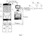
- FIG. 1 A reactor suitable for carrying out plasma-assisted catalytic carbon dioxide hydrogenation process according to the present invention is disclosed in Fig. 1 .
- the reactor according to Fig. 1 which is used only with illustrative purposes, comprises the following parts:
- the high voltage electrodes 2 can be supplied by an AC or DC or pulsed current with a voltage of 10 kV (1.5-3.0 kV, 30-50 mA, current conditions).
- the power injected in these conditions is in the range of 100-140 W.
- the ratio of feed gas H 2 and CO 2 is 1.66, i.e. 10 l/min H 2 and 6 l/min CO 2 .
- the total flow of 16 l/min is used as a plasma-forming gas and a reaction gas.
- Gaseous products composition is measured by gas chromatography and gas analysis methods.
- the condensable products mainly water vapour, are collected in a chamber 7 for in situ water removal and additional hydrogen production to be used again as a reactant in the Sabatier process. Whereas oxygen is captured in the reaction by-products.
- a typical reactor operation and procedure as disclosed in the present invention is as follows: 1. With 25 g of Ni/PCH catalyst with 30 wt% Ni loading corresponding to an GHSV of 7700 1/h, the reactor, shown in Fig. 1 , is supplied with a mixture of CO 2 and H 2 with a flow rate of 6 l/min and 10 l/min, respectively, at atmospheric to 4 bars absolute pressure and at temperature of 20 °C. Distance from the GADP electrodes 2 to the catalyst bed 4 is 1 cm.
- the parameters of the plasma generator current - 1.5 A, voltage - 300 V, frequency - 250 kHz.
- the parameters of the GADP current 40-50 mA, voltage 2.5-3.5 kV. 2.
- the reactor is not cooled, and therefore the temperature profile measured by the K-type thermocouple in the reaction zone at six different places 5 ( Fig. 1 ), starting from the hottest zone close to the GADP electrodes 2 and the coolest zone at the outlet of the reactor, settles down at 550 °C, 380 °C, 310 °C, 240 °C, 150 °C, and 110 °C, respectively. 6. Such a high temperature is reached due to exothermal nature of the catalytic R1 reaction. 7.
- the temperature profile in the reactor measured without the catalyst and the GADP switched on at the same experimental conditions is as follows: 315 °C, 280 °C, 260 °C, 240 °C, 220 °C, and 180 °C, respectively. 8.
Landscapes
- Chemical & Material Sciences (AREA)
- Organic Chemistry (AREA)
- Chemical Kinetics & Catalysis (AREA)
- Engineering & Computer Science (AREA)
- Materials Engineering (AREA)
- Oil, Petroleum & Natural Gas (AREA)
- General Health & Medical Sciences (AREA)
- General Chemical & Material Sciences (AREA)
- Health & Medical Sciences (AREA)
- Combustion & Propulsion (AREA)
- Inorganic Chemistry (AREA)
- Toxicology (AREA)
- Dispersion Chemistry (AREA)
- Organic Low-Molecular-Weight Compounds And Preparation Thereof (AREA)
Abstract
Description
- The present invention relates to the field of synthetic methane production with in-situ produced water/water vapour removal and additional hydrogen generation from it. In particular, the present invention relates to synergetic effect of a gliding arc discharge plasma (GADP) and catalytic carbon dioxide hydrogenation with subsequent produced water removal and additional hydrogen production at low temperatures and atmospheric to moderate-level pressures.
- The exothermic Sabatier reaction produces methane and water during carbon dioxide and hydrogen reaction at stoichiometric ratio of 1:4, temperatures above 300-500 °C, and high pressures 1-10 MPa, and in the presence of a catalyst, usually Ni-based supported on aluminium oxide. The reaction is as follows:

- Beside Ni, other transition metals such as Ru, Rh, Pd and Pt are generally used as catalytic material for methanation in the form of metal nanoparticles (MNP) deposited on various supports (MNP/support). Also, new methanation catalyst support materials, such as metal oxides, modified oxides, metal-organic frameworks, zeolites, mesoporous silica, carbon materials, etc., have been widely investigated to increase its activity and stability.
- Reversible CO2 hydrogenation reaction (Sabatier reaction) requires in-situ water removal to get higher methane yield and selectivity. Therefore, the introduction of water-selective materials (sorbents or membranes) have been widely studied. Among the different water-selective materials that have been proposed and tested in CO2 hydrogenation literature, zeolite materials are the most widely used followed by silica, ceramics, etc. (Faria et al., 2018, https://doi.org/10.1016/j.jcou.2018.05.005).
- Exploration of novel catalysts and supports as well as demonstration of complete value chain and energy-efficient technology for carbon dioxide methanation has received much attention. Recently, plasma-assisted both catalytic and non-catalytic carbon dioxide hydrogenation has been applied to overcome the barriers of the traditional thermo-catalytic process. The use of plasma enables activation of molecules via excitation, dissociation and ionization, thus generating reactive species such as electrons, ions, radicals, exited species, etc. These reactive plasma species contribute to both the gas phase and surface reactions, undertaking new reaction pathways proceeding at ambient temperatures to 200 °C and atmospheric pressures to several bar.
- Therefore, exists the need for synthetic methane production with in-situ water removal in which the process can be carried out at low temperatures and pressures, thus overcoming shortcomings typical for conventional thermal catalytic carbon dioxide hydrogenation process.
- The novelty of the present invention relates to a method performing the gliding arc plasma-catalytic carbon dioxide hydrogenation with in-situ water removal and additional hydrogen production from it via plasma-activated aluminium and water/water vapour reaction at low temperatures and atmospheric to moderate-level pressures of 1-5 bars.
- The present disclosure also relates to a system suitable for performing the process according to the present invention.
-
-
Fig. 1 represents a scheme of a gliding arc discharge plasma (GADP) catalytic reactor for CO2 hydrogenation. -
Fig. 2 represents a multi-point BET plot of a high surface area porous clay heterostructure (PCH) support used for Ni catalyst. -
Fig. 3 shows X-ray diffraction (XRD) patterns of Ni/PCH catalyst. -
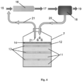
Fig. 4 represents a scheme of reaction chamber for in-situ water/water vapour removal and additional hydrogen production. -
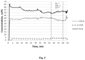
Fig. 5 represents a plot related to additional hydrogen production via activated aluminium and water reaction during GADP catalytic CO2 methanation process. - The present invention relates to a method and a system for performing the following Sabatier reaction (R1) using the synergetic effect of a gliding arc discharge plasma (GADP) and a catalyst with subsequent in-situ water removal and additional hydrogen production via water and plasma-activated aluminium reaction (R2) at low temperatures and atmospheric to moderate-level pressures:
CO2 + 4H2 ↔ CH4 + 2H2O (R1)
3H2O + 2Al → 3H2 + Al2O3 (R2)
- The method characterised in that:
- said catalyst is based on the combination of a high surface area porous clay heterostructure (PCH) support and nickel - Ni/PCH catalyst; and
- said a mixture of CO2 and H2 gases and a catalyst are activated by a gliding arc discharge plasma (GADP); and
- said produced water/water vapour is removed via reaction with plasma-activated aluminium (R2); and
- said additional hydrogen is produced to react with carbon dioxide thus minimizing the initial amount of hydrogen needed for the process.
- The support of Ni-based catalyst is made of a porous high specific surface area (SBET) and pore volumes clay heterostructure formed by chemical method.
- The support of the Ni/PCH catalyst has a high specific surface area SBET up to 1000-1100 m2/g, total pore volume up to 1.15 cm3/g, good dispersion of
Ni nanoparticles D avg 18 nm.Fig. 2 shows the multi-point BET plot of a high surface area porous clay heterostructure support used for Ni catalyst.Fig. 3 shows XRD pattern of the distribution on Ni nanoparticples on the PCH support. - The Ni loading varies from 5 to 30 wt% on the PCH catalyst support. Preferably, the higher the Ni loading, the better performance of the Ni/PCH catalyst is achieved. Table 1 shows evaluation of Ni/PCH catalyst efficiency increasing the Ni loading from 5 to 30 wt%.
Table 1 No. Ni loading wt% Conversion (XCO2), % Selectivity (SCH4), % Yield (YCH4), % 1 5 18.6 18.6 3.44 2 10 28.6 92.0 26.4 3 20 80.0 75.0 60.3 4 30 94.0 94.0 88.6 - The average size of the Ni/PCH catalyst is 3 mm in diameter and 4-5 mm in length. The Ni/PCH catalyst during conventional thermo-catalytic carbon dioxide methanation process is characterized by CO2 conversion of 94%, synthetic CH4 yield of 88.6% and selectivity of 94%, respectively. Process conditions: fixed-bed tube reactor, stoichiometric H2:CO2 ratio 4:1, 10 bars pressure, average 400 °C temperature, and gas hourly space velocity (GHSV) of 756 1/h.
- The Ni/PCH catalyst is reduced under hydrogen flow at 480 °C for 2 hours. The reduced Ni/PCH catalyst is then placed over the surface of the
electrodes 2 of the gliding arc discharge plasma (GADP) in the reactor (Fig. 1 ). The distance between theelectrodes 2 and the catalyst bed 4 is in the range of 1-2 cm. The catalyst is not directly immersed into the GADP due to too high thermal load, potential physical damage and deactivation. - A mixture of gases CO2 and
H 2 3 is activated, i.e. ionized by a GADP then passes through the placed catalyst 4 thus initiating adsorption-desorption catalyst-gas phase interaction reactions. - Gliding arc discharge plasma is used to operate as the main discharge source as it shares both properties typical for thermal and non-thermal plasmas and is suitable for CO2 conversion.
- No external heating is used in the process. GADP is a source of heat. Preferably, the process is carried out at atmospheric to moderate-level up to 5 bars, absolute up to 6 bars pressure.
- Synergy of the GADP activating CO2 and H2 gases via vibrational excitation (different activation mechanism compared to a direct barrier discharge (DBD)) and later activated gas mixture interaction with catalyst via heterogeneous adsorption/desorption reactions to produce ultimate desired product synthetic methane is one of the key novelty of the present invention.
- No other gases, except CO2 and H2, are used to form plasma.
- A reactor suitable for carrying out plasma-assisted catalytic carbon dioxide hydrogenation process according to the present invention is disclosed in
Fig. 1 . The reactor according toFig. 1 , which is used only with illustrative purposes, comprises the following parts: - i. A
cylindrical quartz tube 1, which is the reactor wall. The external part of thetube 1 is covered by a 2 mm thick perforated stainless steel tube to protect the reactor from fracture while working at moderate-level pressures. - ii. At the bottom of the
quartz tube 1, twoelectrodes 2, made of stainless steel, are placed to generate plasma. The distance between theelectrodes 2 can vary from 1-2 mm. The length of theelectrodes 2 is 20 mm and the width is 10 mm. The electrodes have the shape of sails. The electrodes are insulated by a Teflon ring. - iii. Plasma-forming feed gas (CO2 and H2) is supplied via a 2
mm diameter tube 3 installed at the very bottom of the reactor. - iv. The catalyst bed 4 is placed over the
electrodes 2 at the distance from 1-2 cm. - v. A K-type thermocouple
temperature profile probe 5 is placed axially the reactor length in the centre to measure temperature profile every 10 mm at six different points. - vi. A
condenser 6 is used to condense reaction by-product water. - vii. A stainless steel water
removal reaction chamber 7 is used to remove reaction water and produce additional hydrogen via plasma-activated aluminium and water reaction. - viii. A
rotameter 8 is used to measure the flow rate of gaseous reaction products. - ix. A
pressure control valve 9. - x. Gas chromatograph (GC) and
gas analyser 10. - The
high voltage electrodes 2 can be supplied by an AC or DC or pulsed current with a voltage of 10 kV (1.5-3.0 kV, 30-50 mA, current conditions). The power injected in these conditions is in the range of 100-140 W. - The ratio of feed gas H2 and CO2 is 1.66, i.e. 10 l/min H2 and 6 l/min CO2. The total flow of 16 l/min is used as a plasma-forming gas and a reaction gas.
- Gaseous products composition is measured by gas chromatography and gas analysis methods.
- The condensable products, mainly water vapour, are collected in a
chamber 7 for in situ water removal and additional hydrogen production to be used again as a reactant in the Sabatier process. Whereas oxygen is captured in the reaction by-products. This is the second key novelty of the present invention minimizing the need of hydrogen for CO2 methanation process: - I. Aluminium scrap is activated in a glow discharge plasma in the presence of 3-10 Pa of hydrogen with purity not less than 99.00%, or argon with purity not less than 99.00%, or hydrogen and argon mixtures with the best Ar:H2 proportion 70:30 as residual gasses for 10-60 min treatment in plasma with the DC power density up to 10-30 W/cm2. Temperature is 60-110 0C during the plasma process.
- II. 30 g of plasma-activated
hydrophilic aluminium 11 is placed in a chamber 7 (Fig. 4 ) in a layered structure between the layers of NaOH particles 13 (Fig. 4 ). The proportion of layers thickness between the layers ofNaOH particles 13, acting as a reaction promoter between plasma-activated aluminium and water molecules, and activatedaluminium layer 11 is 1:5 by volume. Astainless steel mesh 14 with pores diameters of 1 mm andglass wool 12 were used at the inlet and outlet of reaction molecules to prevent aluminium and reaction by-products Bayerite - Al(OH)3, thermonatrite - Na2CO3•H2O migration from thereaction chamber 7. - III. In case a
water condensation equipment 6 is present (Fig. 1 ), H2O molecules enter thechamber 7 were reaction between activatedaluminium 11 and condensed water molecules (R2 reaction) takes place and pure H2 gas and reaction by-products Bayerite - Al(OH)3, thermonatrite - Na2CO3•H2O are produced. The other gases, such as CH4, CO2 unreacted and H2 unreacted, also entering thechamber 7, have no impact on reaction between activated aluminium and water. They just leave the chamber and go for analysis. - The present invention is further disclosed by way of examples which only intend to illustrate the present invention and by no means are limiting the scope thereof.
- A typical reactor operation and procedure as disclosed in the present invention is as follows:
1. With 25 g of Ni/PCH catalyst with 30 wt% Ni loading corresponding to an GHSV of 7700 1/h, the reactor, shown inFig. 1 , is supplied with a mixture of CO2 and H2 with a flow rate of 6 l/min and 10 l/min, respectively, at atmospheric to 4 bars absolute pressure and at temperature of 20 °C. Distance from theGADP electrodes 2 to the catalyst bed 4 is 1 cm. The parameters of the plasma generator: current - 1.5 A, voltage - 300 V, frequency - 250 kHz. The parameters of the GADP: current 40-50 mA, voltage 2.5-3.5 kV.
2. Without the GADP and presence of Ni/PCH catalyst at atmospheric and increased pressure to 4 bars, no change in the composition of outlet gases is observed. When the GADP is switched on, the temperature increases slowly and after 2 minutes the production of methane and water vapour is obtained at around 60-80 °C and atmospheric pressure, which is impossible to obtain in conventional thermo-catalytic Sabatier reaction.
3. With the GADP switched on and absence of Ni/PCH catalyst, no methane is obtained. Plasma activates and converts only CO2 to CO and H2 to H.
4. The steady state conditions producing methane are reached after around 7 minutes.
5. The temperature in the reactor is not controlled, i.e. the reactor is not cooled, and therefore the temperature profile measured by the K-type thermocouple in the reaction zone at six different places 5 (Fig. 1 ), starting from the hottest zone close to theGADP electrodes 2 and the coolest zone at the outlet of the reactor, settles down at 550 °C, 380 °C, 310 °C, 240 °C, 150 °C, and 110 °C, respectively.
6. Such a high temperature is reached due to exothermal nature of the catalytic R1 reaction.
7. The temperature profile in the reactor measured without the catalyst and the GADP switched on at the same experimental conditions is as follows: 315 °C, 280 °C, 260 °C, 240 °C, 220 °C, and 180 °C, respectively.
8. The efficiency of the GADP catalytic process for CO2 methanation is summarized in Table 2.Table 2 Pressure in reactor, bar Ni/PCH catalyst with 30 wt% Ni loading XCO2, % XH2, % CH4, vol% CH4 T, vol% SCH4, % YCH4, % CB1, % SER2, kWh/m3 SER, kJ/ mol 1 22.29 48.01 6.4 21.9 18.99 4.23 88.98 3.06 246.21 2 26.41 52.87 8.3 22.0 20.21 5.34 87.34 2.43 195.30 3 26.07 55.01 11.5 22.0 28.03 7.31 89.77 1.77 142.66 4 27.09 54.01 13.3 22.0 33.27 9.02 89.01 1.26 101.16 TCH4 - methane concentration at thermodynamic equilibrium
1CB - carbon balance
2SER -specific energy requirements
10. Pressure has a positive impact on higher conversion of CO2 and CH4 selectivity and yield. However, the reaction in the present invention proceeds at atmospheric pressure and low temperature as conventional CO2 methanation (Sabatier) reaction is limited to such conditions.
11. The specific energy requirements (SER) are in the range of 3.46 to 8.42 kWh/m3 (or 278.19 to 677.07 kJ/mol). This is mostly depended on a higher CO2 and H2 conversion and CH4 concentration at increased pressure.
12. High value of carbon balance around 89% show that carbon deposition is minimal to clog catalyst pores thus reducing its efficiency. No solid carbon deposition on catalyst surface is observed. - Another GADP catalytic reactor operation and procedure as disclosed in the present invention is as follows:
- 1. With 25 g of Ni/PCH catalyst with 30 wt% Ni loading corresponding to an GHSV of 7700 1/h, the reactor is supplied with a mixture of CO2 and H2 with a flow rate of 6 l/min and 10 l/min, respectively, at atmospheric to 4 bars absolute pressure at temperature of 20 °C. Distance from the
GADP electrodes 2 to the catalyst bed 4 is 1 cm. The parameters of the plasma generator: current - 1.5 A, voltage - 300 V, frequency - 250 kHz. The parameters of the GADP: current 40-50 mA, voltage 2.5-3.5 kV. 30 g of plasma-activated hydrophilic aluminium is placed in the developed innovative chamber to react with condensed water. - 2. In situ water removal with subsequent additional hydrogen production via R2 reaction is carried out.
Fig. 4 shows how the water is removed and additional hydrogen is produced during plasma-catalytic carbon dioxide hydrogenation (15 - reaction gases: CO2 + H2, 16 - GADP catalytic reactor (or traditional Sabatier reactor), 17 - product gases: CH4 + H2O, plus unreacted CO2 and H2, 18 - condenser, 19 - product gases without water: CH4, plus unreacted CO2 and H2, 20 - condensed water, 7 - chamber, 14 - stainless steel mesh, 12 - glass wool, 13 - NaOH, 11 - plasma-activated hydrophilic aluminium, 21 - additional hydrogen production). A mixture of gases (CH4 produced, CO2 and H2 unreacted), in case of entering thechamber 7, has no direct impact on additional hydrogen production. They simply leave the chamber having no direct impact on condensed water and activated aluminium reaction to produce additional hydrogen. - 3.
Fig. 5 shows additional H2 production according to R2 reaction. Additional H2 production starts after 47 minutes and ends after 60 minutes of the continuous operation of the process producing methane. The concentration of product gases is measured by a gas analyser. - 4. During this process, beside the reaction between condensed water and activated aluminium (R2 reaction), a reversible water-gas shift (RWGS) reaction also dominates. According to RWGS the concentration of H2 and CO2 should decrease, and the one of CO and H2O should increase. However, H2 concentration increased up to 5-6 vol% (CO2 decreased up to 5 vol%, CO increased up to 2-3%) implying the presence of the R2 reaction.
- 5. Produced additional hydrogen could be used as a reactant in CO2 methanation process, thus minimizing the need of green hydrogen needed for the reaction.
Claims (11)
- A method for performing the reactions (R1), (R2) with catalyst and in-situ water/water vapour removal and additional hydrogen production:
CO2 + 4H2 ↔ CH4 + 2H2O (R1)
3H2O + 2Al - 3H2 + Al2O3 (R2)
the method characterised in that:- the catalyst is based on the combination of a high surface area porous clay heterostructure (PCH) support and nickel - Ni/PCH catalyst; and- a mixture of CO2 and H2 gases and a catalyst is activated by a gliding arc discharge plasma (GADP); and- the produced water/water vapour is removed via reaction with plasma-activated aluminium (R2); and- the additional hydrogen is produced to react with carbon dioxide thus minimizing the initial amount of hydrogen needed for the process. - The method according to claim 1, characterized in that the catalyst is based on the combination of nickel and a high surface area porous clay heterostructure (PCH) as a support formed by chemical method.
- The method according to claim 1, characterized in that the Ni/PCH catalyst comprises nickel 5 to 30 wt%, most preferably 30 wt%, and a PCH support with initial high surface area, most preferably of up to 1000-1100 m2/g, total pore volume up to 1.15 cm3/g, and dispersion of Ni nanoparticles (Davg 18 nm).
- The method according to claim 1, characterized in that the Ni/PCH catalyst during conventional thermo-catalytic carbon dioxide methanation process is characterized by CO2 conversion of 94.0%, CH4 yield of 88.6%, and selectivity of 94%, respectively.
- The method according to claim 1, characterized in that the gliding arc discharge plasma (GADP) is used to activate carbon dioxide and hydrogen via vibrational excitation pathway and active sites of Ni/PCH catalyst at atmospheric to moderate pressures up to 5 bars and low temperatures to produce synthetic methane.
- The method according to claim 1 or 5, characterized in that no other gases, except CO2 and H2, are used to form plasma and active medium of gas mixture to interact with catalyst via heterogeneous adsorption/desorption reactions to produce synthetic methane and water.
- The method according to any of claims 1 to 6, characterized in that the hydrogen and carbon dioxide are provided in a H2/CO2 ratio of 1.66.
- The method according to claim 1 to 7, characterized in that the synthetic methane production, according to R1 reaction, starts preferably at 60 to 80 °C temperature, most preferably at 60 °C temperature, and atmospheric to moderate-level pressure up to 5 bars, most preferably atmospheric pressure, and after two minutes of plasma ignition.
- The method according to claim 1 to 8, characterized in that the water molecules, produced after R1 reaction, react with activated aluminium (R2 reaction) instantly after entering the reaction zone and are converted to pure hydrogen, and oxygen is captured in reaction by-products Bayerite - Al(OH)3 and Na2CO3•H2O thermonatrite.
- The method according to claim 1 to 9, characterized in that said gliding arc discharge Ni/PCH catalytic carbon dioxide hydrogenation with in-situ water removal and additional hydrogen production at atmospheric to moderate-level pressure up to 5 bars and synthetic methane production starting at 60 °C temperature is characterized by CO2 conversion of 27.09%, H2 conversion of 54.01%, CH4 concentration of 13.3 vol.%, CH4 yield of 9.02%, carbon balance of 89.01%, and specific energy requirements of 1.26 kWh/m3 or 101.16 kJ/mol.
- A system for producing synthetic methane from carbon dioxide and hydrogen with in-situ water removal and additional hydrogen production characterised by comprising a gliding arc discharge (GAD) device arranged to generate plasma; a catalyst comprising nickel on a support comprising porous clay heterostructure comprising a high specific surface area of 1000-1100 m2/g; a reaction chamber for in-situ water/water vapour removal and additional hydrogen production.
Priority Applications (1)
| Application Number | Priority Date | Filing Date | Title |
|---|---|---|---|
| EP23163031.0A EP4434621B1 (en) | 2023-03-21 | 2023-03-21 | Method and system for plasma-catalytic carbon dioxide hydrogenation with in-situ water removal and additional hydrogen production |
Applications Claiming Priority (1)
| Application Number | Priority Date | Filing Date | Title |
|---|---|---|---|
| EP23163031.0A EP4434621B1 (en) | 2023-03-21 | 2023-03-21 | Method and system for plasma-catalytic carbon dioxide hydrogenation with in-situ water removal and additional hydrogen production |
Publications (2)
| Publication Number | Publication Date |
|---|---|
| EP4434621A1 true EP4434621A1 (en) | 2024-09-25 |
| EP4434621B1 EP4434621B1 (en) | 2026-04-29 |
Family
ID=85781667
Family Applications (1)
| Application Number | Title | Priority Date | Filing Date |
|---|---|---|---|
| EP23163031.0A Active EP4434621B1 (en) | 2023-03-21 | 2023-03-21 | Method and system for plasma-catalytic carbon dioxide hydrogenation with in-situ water removal and additional hydrogen production |
Country Status (1)
| Country | Link |
|---|---|
| EP (1) | EP4434621B1 (en) |
Cited By (1)
| Publication number | Priority date | Publication date | Assignee | Title |
|---|---|---|---|---|
| CN119733355A (en) * | 2024-11-21 | 2025-04-01 | 华东理工大学 | System and method for low-temperature plasma coupled dual-functional materials to synergize carbon dioxide capture and in-situ conversion |
Citations (2)
| Publication number | Priority date | Publication date | Assignee | Title |
|---|---|---|---|---|
| EP2650401A1 (en) * | 2012-04-10 | 2013-10-16 | Siemens Aktiengesellschaft | Power plant based methanation system |
| CN107413346A (en) * | 2017-06-07 | 2017-12-01 | 广西大学 | A kind of preparation method of catalyst for carbon dioxide methanation |
-
2023
- 2023-03-21 EP EP23163031.0A patent/EP4434621B1/en active Active
Patent Citations (2)
| Publication number | Priority date | Publication date | Assignee | Title |
|---|---|---|---|---|
| EP2650401A1 (en) * | 2012-04-10 | 2013-10-16 | Siemens Aktiengesellschaft | Power plant based methanation system |
| CN107413346A (en) * | 2017-06-07 | 2017-12-01 | 广西大学 | A kind of preparation method of catalyst for carbon dioxide methanation |
Non-Patent Citations (1)
| Title |
|---|
| ASHOK JANGAM ET AL: "A review of recent catalyst advances in CO2 methanation processes", CATALYSIS TODAY, ELSEVIER, AMSTERDAM, NL, vol. 356, 29 July 2020 (2020-07-29), pages 471 - 489, XP086304345, ISSN: 0920-5861, [retrieved on 20200729], DOI: 10.1016/J.CATTOD.2020.07.023 * |
Cited By (1)
| Publication number | Priority date | Publication date | Assignee | Title |
|---|---|---|---|---|
| CN119733355A (en) * | 2024-11-21 | 2025-04-01 | 华东理工大学 | System and method for low-temperature plasma coupled dual-functional materials to synergize carbon dioxide capture and in-situ conversion |
Also Published As
| Publication number | Publication date |
|---|---|
| EP4434621B1 (en) | 2026-04-29 |
Similar Documents
| Publication | Publication Date | Title |
|---|---|---|
| EP0564526B1 (en) | Process for the conversion of methane to synthesis gas | |
| Brungs et al. | Comparison of the group V and VI transition metal carbides for methane dry reforming and thermodynamic prediction of their relative stabilities | |
| Waldron et al. | Production of hydrogen by cyclic sorption enhanced reaction process | |
| US6929668B2 (en) | Process for production of hydrogen by partial oxidation of hydrocarbons | |
| EP3050865B1 (en) | Process for the reduction of carbon dioxide to methane by dbd plasma-activated catalyst | |
| JP2010516610A (en) | Method and system for producing hydrogen-enriched fuels using microwave-induced methane decomposition for catalysts | |
| AU2007351434A1 (en) | Methods and systems of producing molecular hydrogen using a plasma system | |
| EP2106385A2 (en) | Method and system for producing a hydrogen enriched fuel using microwave assisted methane plasma decomposition on catalyst | |
| EP4434621A1 (en) | Method and system for plasma-catalytic carbon dioxide hydrogenation with in-situ water removal and additional hydrogen production | |
| US20230133746A1 (en) | Process for Producing Hydrogen, Carbon, and Ethylene From Methane-Containing Feedstock | |
| CN117567242B (en) | Method for preparing methanol in one step using methane and carbon dioxide as raw materials | |
| JP2023073692A (en) | Hydrogen production method, and hydrogen production facility | |
| WO2021255421A1 (en) | Co2 methanation using plasma catalysis | |
| Fasolini et al. | Pure H2 production by methane oxy-reforming over Rh-Mg-Al hydrotalcite-derived catalysts coupled with a Pd membrane | |
| JP5842540B2 (en) | Method and apparatus for producing methane from CO2 and / or CO | |
| KR20150047993A (en) | Method for producing at least one selected from methanol, formaldehyde and hydrocarbon having C2 or more, and apparatus for conversion of methane, using plasma-catalyst | |
| KR100561166B1 (en) | Apparatus and method for syngas production using atmospheric barrier discharge reaction | |
| Li et al. | Methane oxidation to synthesis gas using lattice oxygen in La1− xSrxFeO3 perovskite oxides instead of molecular oxygen | |
| JP2006517176A (en) | Silicon carbide supported catalyst for partial oxidation of natural gas to syngas | |
| Matsui et al. | Reactivity of carbon species formed on supported noble metal catalysts in methane conversion reactions | |
| US7285189B2 (en) | Method for steam reforming of chain hydrocarbon | |
| KR100589202B1 (en) | Syngas production apparatus capable of controlling composition of syngas and syngas production method using the same | |
| KR20200047288A (en) | Process for Regenerating Zeolite Catalysts for Carbonylation of Dimethyl Ether by Plasma Treatment | |
| TWI501920B (en) | Production method and apparatus for hydrogen | |
| US20020000539A1 (en) | Bulk nickel catalysts and processes for the production of syngas |
Legal Events
| Date | Code | Title | Description |
|---|---|---|---|
| PUAI | Public reference made under article 153(3) epc to a published international application that has entered the european phase |
Free format text: ORIGINAL CODE: 0009012 |
|
| STAA | Information on the status of an ep patent application or granted ep patent |
Free format text: STATUS: THE APPLICATION HAS BEEN PUBLISHED |
|
| AK | Designated contracting states |
Kind code of ref document: A1 Designated state(s): AL AT BE BG CH CY CZ DE DK EE ES FI FR GB GR HR HU IE IS IT LI LT LU LV MC ME MK MT NL NO PL PT RO RS SE SI SK SM TR |
|
| STAA | Information on the status of an ep patent application or granted ep patent |
Free format text: STATUS: REQUEST FOR EXAMINATION WAS MADE |
|
| 17P | Request for examination filed |
Effective date: 20250116 |
|
| STAA | Information on the status of an ep patent application or granted ep patent |
Free format text: STATUS: EXAMINATION IS IN PROGRESS |
|
| 17Q | First examination report despatched |
Effective date: 20250610 |
|
| GRAP | Despatch of communication of intention to grant a patent |
Free format text: ORIGINAL CODE: EPIDOSNIGR1 |
|
| STAA | Information on the status of an ep patent application or granted ep patent |
Free format text: STATUS: GRANT OF PATENT IS INTENDED |
|
| RIC1 | Information provided on ipc code assigned before grant |
Ipc: B01J 23/755 20060101AFI20251001BHEP Ipc: B01J 21/16 20060101ALI20251001BHEP Ipc: B01J 19/08 20060101ALI20251001BHEP Ipc: C07C 1/12 20060101ALI20251001BHEP Ipc: C10L 3/08 20060101ALI20251001BHEP Ipc: C01B 3/08 20060101ALI20251001BHEP Ipc: B01J 8/02 20060101ALI20251001BHEP Ipc: B01J 35/45 20240101ALI20251001BHEP Ipc: B01J 35/61 20240101ALI20251001BHEP Ipc: B01J 35/63 20240101ALI20251001BHEP Ipc: B01J 35/30 20240101ALI20251001BHEP |
|
| INTG | Intention to grant announced |
Effective date: 20251103 |
|
| GRAS | Grant fee paid |
Free format text: ORIGINAL CODE: EPIDOSNIGR3 |
|
| GRAA | (expected) grant |
Free format text: ORIGINAL CODE: 0009210 |
|
| STAA | Information on the status of an ep patent application or granted ep patent |
Free format text: STATUS: THE PATENT HAS BEEN GRANTED |
|
| AK | Designated contracting states |
Kind code of ref document: B1 Designated state(s): AL AT BE BG CH CY CZ DE DK EE ES FI FR GB GR HR HU IE IS IT LI LT LU LV MC ME MK MT NL NO PL PT RO RS SE SI SK SM TR |
|
| REG | Reference to a national code |
Ref country code: CH Ref legal event code: F10 Free format text: ST27 STATUS EVENT CODE: U-0-0-F10-F00 (AS PROVIDED BY THE NATIONAL OFFICE) Effective date: 20260429 |