EP4434561A1 - Port cannula system with a flexible tube - Google Patents
Port cannula system with a flexible tube Download PDFInfo
- Publication number
- EP4434561A1 EP4434561A1 EP23162908.0A EP23162908A EP4434561A1 EP 4434561 A1 EP4434561 A1 EP 4434561A1 EP 23162908 A EP23162908 A EP 23162908A EP 4434561 A1 EP4434561 A1 EP 4434561A1
- Authority
- EP
- European Patent Office
- Prior art keywords
- port
- catheter
- skin
- fixation element
- flexible tube
- Prior art date
- Legal status (The legal status is an assumption and is not a legal conclusion. Google has not performed a legal analysis and makes no representation as to the accuracy of the status listed.)
- Withdrawn
Links
- 239000000463 material Substances 0.000 claims 4
- 229920003023 plastic Polymers 0.000 claims 3
- 239000004033 plastic Substances 0.000 claims 3
- 230000002787 reinforcement Effects 0.000 claims 2
- 239000000853 adhesive Substances 0.000 claims 1
- 230000001070 adhesive effect Effects 0.000 claims 1
- 239000000919 ceramic Substances 0.000 claims 1
- 239000012530 fluid Substances 0.000 claims 1
- 239000012528 membrane Substances 0.000 claims 1
- 239000002184 metal Substances 0.000 claims 1
Images


Classifications
-
- A—HUMAN NECESSITIES
- A61—MEDICAL OR VETERINARY SCIENCE; HYGIENE
- A61M—DEVICES FOR INTRODUCING MEDIA INTO, OR ONTO, THE BODY; DEVICES FOR TRANSDUCING BODY MEDIA OR FOR TAKING MEDIA FROM THE BODY; DEVICES FOR PRODUCING OR ENDING SLEEP OR STUPOR
- A61M5/00—Devices for bringing media into the body in a subcutaneous, intra-vascular or intramuscular way; Accessories therefor, e.g. filling or cleaning devices, arm-rests
- A61M5/46—Devices for bringing media into the body in a subcutaneous, intra-vascular or intramuscular way; Accessories therefor, e.g. filling or cleaning devices, arm-rests having means for controlling depth of insertion
-
- A—HUMAN NECESSITIES
- A61—MEDICAL OR VETERINARY SCIENCE; HYGIENE
- A61M—DEVICES FOR INTRODUCING MEDIA INTO, OR ONTO, THE BODY; DEVICES FOR TRANSDUCING BODY MEDIA OR FOR TAKING MEDIA FROM THE BODY; DEVICES FOR PRODUCING OR ENDING SLEEP OR STUPOR
- A61M39/00—Tubes, tube connectors, tube couplings, valves, access sites or the like, specially adapted for medical use
- A61M39/02—Access sites
- A61M39/0208—Subcutaneous access sites for injecting or removing fluids
-
- A—HUMAN NECESSITIES
- A61—MEDICAL OR VETERINARY SCIENCE; HYGIENE
- A61M—DEVICES FOR INTRODUCING MEDIA INTO, OR ONTO, THE BODY; DEVICES FOR TRANSDUCING BODY MEDIA OR FOR TAKING MEDIA FROM THE BODY; DEVICES FOR PRODUCING OR ENDING SLEEP OR STUPOR
- A61M39/00—Tubes, tube connectors, tube couplings, valves, access sites or the like, specially adapted for medical use
- A61M39/02—Access sites
- A61M39/04—Access sites having pierceable self-sealing members
-
- A—HUMAN NECESSITIES
- A61—MEDICAL OR VETERINARY SCIENCE; HYGIENE
- A61M—DEVICES FOR INTRODUCING MEDIA INTO, OR ONTO, THE BODY; DEVICES FOR TRANSDUCING BODY MEDIA OR FOR TAKING MEDIA FROM THE BODY; DEVICES FOR PRODUCING OR ENDING SLEEP OR STUPOR
- A61M5/00—Devices for bringing media into the body in a subcutaneous, intra-vascular or intramuscular way; Accessories therefor, e.g. filling or cleaning devices, arm-rests
- A61M5/178—Syringes
- A61M5/31—Details
- A61M5/32—Needles; Details of needles pertaining to their connection with syringe or hub; Accessories for bringing the needle into, or holding the needle on, the body; Devices for protection of needles
- A61M5/3287—Accessories for bringing the needle into the body; Automatic needle insertion
-
- A—HUMAN NECESSITIES
- A61—MEDICAL OR VETERINARY SCIENCE; HYGIENE
- A61M—DEVICES FOR INTRODUCING MEDIA INTO, OR ONTO, THE BODY; DEVICES FOR TRANSDUCING BODY MEDIA OR FOR TAKING MEDIA FROM THE BODY; DEVICES FOR PRODUCING OR ENDING SLEEP OR STUPOR
- A61M5/00—Devices for bringing media into the body in a subcutaneous, intra-vascular or intramuscular way; Accessories therefor, e.g. filling or cleaning devices, arm-rests
- A61M5/42—Devices for bringing media into the body in a subcutaneous, intra-vascular or intramuscular way; Accessories therefor, e.g. filling or cleaning devices, arm-rests having means for desensitising skin, for protruding skin to facilitate piercing, or for locating point where body is to be pierced
-
- A—HUMAN NECESSITIES
- A61—MEDICAL OR VETERINARY SCIENCE; HYGIENE
- A61M—DEVICES FOR INTRODUCING MEDIA INTO, OR ONTO, THE BODY; DEVICES FOR TRANSDUCING BODY MEDIA OR FOR TAKING MEDIA FROM THE BODY; DEVICES FOR PRODUCING OR ENDING SLEEP OR STUPOR
- A61M5/00—Devices for bringing media into the body in a subcutaneous, intra-vascular or intramuscular way; Accessories therefor, e.g. filling or cleaning devices, arm-rests
- A61M5/14—Infusion devices, e.g. infusing by gravity; Blood infusion; Accessories therefor
- A61M5/158—Needles for infusions; Accessories therefor, e.g. for inserting infusion needles, or for holding them on the body
- A61M2005/1581—Right-angle needle-type devices
-
- A—HUMAN NECESSITIES
- A61—MEDICAL OR VETERINARY SCIENCE; HYGIENE
- A61M—DEVICES FOR INTRODUCING MEDIA INTO, OR ONTO, THE BODY; DEVICES FOR TRANSDUCING BODY MEDIA OR FOR TAKING MEDIA FROM THE BODY; DEVICES FOR PRODUCING OR ENDING SLEEP OR STUPOR
- A61M5/00—Devices for bringing media into the body in a subcutaneous, intra-vascular or intramuscular way; Accessories therefor, e.g. filling or cleaning devices, arm-rests
- A61M5/14—Infusion devices, e.g. infusing by gravity; Blood infusion; Accessories therefor
- A61M5/158—Needles for infusions; Accessories therefor, e.g. for inserting infusion needles, or for holding them on the body
- A61M2005/1585—Needle inserters
-
- A—HUMAN NECESSITIES
- A61—MEDICAL OR VETERINARY SCIENCE; HYGIENE
- A61M—DEVICES FOR INTRODUCING MEDIA INTO, OR ONTO, THE BODY; DEVICES FOR TRANSDUCING BODY MEDIA OR FOR TAKING MEDIA FROM THE BODY; DEVICES FOR PRODUCING OR ENDING SLEEP OR STUPOR
- A61M5/00—Devices for bringing media into the body in a subcutaneous, intra-vascular or intramuscular way; Accessories therefor, e.g. filling or cleaning devices, arm-rests
- A61M5/14—Infusion devices, e.g. infusing by gravity; Blood infusion; Accessories therefor
- A61M5/158—Needles for infusions; Accessories therefor, e.g. for inserting infusion needles, or for holding them on the body
- A61M2005/1586—Holding accessories for holding infusion needles on the body
-
- A—HUMAN NECESSITIES
- A61—MEDICAL OR VETERINARY SCIENCE; HYGIENE
- A61M—DEVICES FOR INTRODUCING MEDIA INTO, OR ONTO, THE BODY; DEVICES FOR TRANSDUCING BODY MEDIA OR FOR TAKING MEDIA FROM THE BODY; DEVICES FOR PRODUCING OR ENDING SLEEP OR STUPOR
- A61M39/00—Tubes, tube connectors, tube couplings, valves, access sites or the like, specially adapted for medical use
- A61M39/02—Access sites
- A61M2039/0205—Access sites for injecting media
-
- A—HUMAN NECESSITIES
- A61—MEDICAL OR VETERINARY SCIENCE; HYGIENE
- A61M—DEVICES FOR INTRODUCING MEDIA INTO, OR ONTO, THE BODY; DEVICES FOR TRANSDUCING BODY MEDIA OR FOR TAKING MEDIA FROM THE BODY; DEVICES FOR PRODUCING OR ENDING SLEEP OR STUPOR
- A61M39/00—Tubes, tube connectors, tube couplings, valves, access sites or the like, specially adapted for medical use
- A61M39/02—Access sites
- A61M39/0208—Subcutaneous access sites for injecting or removing fluids
- A61M2039/0226—Subcutaneous access sites for injecting or removing fluids having means for protecting the interior of the access site from damage due to the insertion of a needle
Definitions
- the invention relates to a port cannula system for puncturing a port.
- Port cannulas are used for puncturing implanted port catheters.
- An implanted port catheter in short also referred to as port, is arranged under the skin of a patient and typically defines a volume covered by a membrane. The volume of the port is connected to a catheter that opens into a vessel or other treatment site.
- a port cannula with a needle is used to administer a liquid into the port. The needle is pressed through the skin of the patient and through the membrane into the volume so that the liquid can be filled into the volume of the port and, thereby, administered to the patient.
- US 5,135,502 A proposes a solid introducer for a catheter to a port with the same disadvantages as described above.
- DE 697 30 513 T2 describes a security-catheter arrangement which is applicable for different weights and sizes of the various patients.
- these two solutions are relatively inconvenient in use and, therefore, both have not been accepted in wider practice.
- a port cannula system for puncturing a port comprises a cannula and a catheter having a flexible tube surrounding the cannula.
- the port cannula system further comprises a fixation element.
- the fixation element is adapted to fix the catheter to the skin of a person such that the fixation element is arranged between the catheter and the skin.
- the fixation element of the proposed solution both provides a reference and an aid for correctly applying the catheter to the port at the required depth, as well as a secure and comfortable fixture of the catheter on the skin. Since the tube is flexible, the catheter may be bent so as to extend in parallel to the skin.
- the fixation element may comprise a locking portion for removably locking the catheter to the fixation element.
- the catheter may be fixed on the skin in a particularly simple and reliable manner.
- the fixation element has a skin-facing side for contacting the skin when the fixation element is fixed to the skin.
- the locking portion may be arranged on an upper side of the fixation element.
- the upper side is, e.g., opposite the skin-facing side.
- the skin-facing side is provided with an adhesive for fixation to the skin.
- the application can be particularly reliable and simple.
- the locking portion and the catheter may form a snap-in connection.
- the locking portion and the catheter may be engageable with one another.
- the locking portion and the catheter may comprise a hook-and-loop fastener.
- the port cannula system may comprise a scale configured to indicate a length of the flexible tube pierced into the skin. This can simplify the application and improve the precision thereof.
- the scale is provided on the fixation element, wherein an indicator indicating the length (of the flexible tube pierced into the skin) on the scale is provided on the catheter.
- the scale may be provided on the flexible tube, wherein an indicator indicating the length (of the flexible tube pierced into the skin) on the scale is provided on the fixation element. This allows to easily adjust the correct length without additional components. For example, the length may be documented and used for another infusion at a later point in time if the patient has not gained or lost weight.
- the catheter may comprise a connector for establishing a fluid connection between the flexible tube and another part, e.g., a connection hose.
- a connector for establishing a fluid connection between the flexible tube and another part, e.g., a connection hose.
- the port cannula system may further comprise a tip protection element removably arranged at the connector and adapted to cover a tip of the cannula when the cannula is withdrawn from the catheter. This allows to prevent needle-stick injuries.
- the fixation element may comprise a hole.
- the catheter (more precisely, the flexible tube thereof) may extend through the hole and/or may be adapted to extend through the hole. This allows a reliable functionality and a protected puncture site. Furthermore, the position of the flexible tube is secured with respect to the puncture site and port via the fixation element. Unintentional removal of the flexible tube, for example upon movement of the patient is prevented.
- the fixation element comprises for example a plate. In the state fixed to the skin, the plate is in planar abutment with the skin.
- the plate is, e.g., made of a firm, yet flexible material such as silicone to be comfortable to wear for the patient.
- a hole is formed in the plate.
- the flexible tube of the catheter extends through the hole, into the skin and inside the port under the skin.
- the flexible tube may comprise a plastics material. By this, a reliable function can be provided.
- the cannula may be made of a metal, e.g., steel.
- the flexible tube comprises a reinforcement, e.g., at its distal end.
- the reinforcement may have a larger stiffness than other portions of the flexible tube.
- the reinforcement can support the flexible tube against elastic forces of the port membrane. This allows to avoid that the membrane squeezes the flexible tube together.
- a softer material can be used for the flexible tube.
- the reinforcement may comprise, or consist of, a ceramics material, an elastically bendable metal or a plastics material being more rigid than the plastics material of the flexible tube. This allows to further improve the reinforcement.
- the distal end of the flexible tube may be tapered, e.g., sharpened. This allows to facilitate the application of the catheter.
- the port cannula system may further comprise an implantable port comprising a membrane adapted to be punctured by the cannula and the flexible tube surrounding the cannula.
- port cannula systems for puncturing a port shall be described.
- the embodiments described herein shall not be construed as limiting for the scope of the invention.
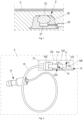
- Fig. 1 shows an implantable port catheter, in the following referred to as port 2.
- the port 2 is shown in a state implanted under the skin 3 of a person.
- the port 2 comprises a housing 20which defines an interior volume 21.
- a membrane 22 of the port 2 closes the volume 21.
- the volume 21 may also be referred to as infusion chamber.
- a catheter 23 is attached to the housing 20 and in fluid connection with the volume 21.
- the catheter 23 establishes a connection of the port 2 to a tissue, for example a vein.
- the membrane 22 is pierced via the skin 3 by means of a port cannula.
- the port cannula establishes the connection between the infusion chamber volume 21 formed in the housing 20, e.g., to an infusion bag.
- a port catheter like the port 2 shown in Fig. 1 can have an implantation time of up to 5 years. Accordingly, the port 2 may be punctured often by a port cannula.
- the membrane 22 is made of a suitable material, e.g., silicone.
- Figs. 2-4 illustrate a port cannula system 1 for puncturing the port 2 of Fig. 1 .
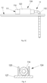
- Fig. 3A shows a side view of the port cannula system 1.
- the cannula 10 is arranged in the flexible tube 110 of the catheter 11.
- the rigid cannula 10 stiffens the flexible tube 110.
- a tip 100 of the cannula 10 projects from the flexible tube 110.
- the tip 100 is sharpened.
- a distal end 113 of the catheter 11 is arranged adjacent the cannula 10 tip 100.
- the distal end 113 of the catheter 11 is tapered.
- the catheter 11 with the cannula 10 can be punctured into the skin 3 and into the port 2 under the skin 3.
- the fixation element 12 may be laid on the skin 3. Alternatively, it may held upwards for using a scale 13 provided on the fixation element 12, see Fig. 2 .
- the body 114 of the catheter 11 comprises an indicator 14, in this example a line.
- the indicator 14 indicates the puncturing depth on the scale 13.
- the fixation element 12 comprises a locking portion 120 for removably locking the catheter 11 to the fixation element 12.
- the locking portion 120 is arranged on the upper side 122 of the fixation element 12.
- the cannula 10 may be removed.
- the cannula 10 comprises a body 102, which protrudes from the body 114 of the catheter 11.
- the body 102 can be used to manually pull the cannula 10 out of the catheter.
- Fig. 3B shows the catheter 11 and the fixation element 12 without the cannula 10. Therefore, after removal of the cannula 10, the flexible tube 110 can be easily bent. Thus, after removing the cannula 10, the flexible tube 110 can be bent so as to fix the body 114 of the catheter 11 on the locking portion 120 of the fixation element 12.
- the body 114 then extends substantially perpendicular to the part of the flexible tube punctured into the skin 3 and port 2.
- the scale 13 is provided on the upper side 122 of the plate 127 and facilitates the adjustment and inspection of the correct puncturing depth.
- the scale provides an indication in cm and mm.
- the fixation element 12 is rigid.
- the fixation element 12 is made of plastics. Therefore, the fixation element 12 protects the puncture site.
- the body 114 of the catheter 11 is fixedly retained and supported on the fixation element 12, it is laid flat on the skin 3, so that it does not protrude much from the skin 3. This makes it both well protected and securely fixed on the skin 3, as well as comfortable for the patient.
- the locking portion 120 of this example comprises two sidewalls between which the body 114 of the catheter 11 can be placed.
- the locking portion 120 forms a snap-in connection 124 together with the body 114.
- the sidewalls of the locking portion 120 comprise inwardly facing protrusions below which the body 114 may be snapped in.
- the body 114 of the catheter 11 When fixed to the fixation element 12, the body 114 of the catheter 11 extends along the length of the plate 127 of the fixation element 12.
- the body 114 of the catheter 11 also forms a connector 111 for connection to a fluid supply.
- a connector 150 of a connection hose 15 can be brought in fluid connection to the connector 111 of the catheter 11.
- the connection hose 15 is provided with an NAC or Luer lock 17 for connection with a supply, such as an infusion pump or the like.
- the fixation element 12 also facilitates removal of the catheter 11, because the catheter 11 may be pulled while pushing against the fixation element 12.
- Fig. 5 shows another option for fixing the catheter 11' body to the fixation element 12', namely, using two hook-and-loop fastener 125A, 125B parts.
- one part of the hook-and-loop fastener 125A is fixed to the catheter 11' body
- the other part of the hook-and-loop fastener 125B is fixed to the fixation element 12', namely to the upper side of the plate 127 thereof.
- a scale 13' is provided on the flexible tube 110, wherein an indicator 14' indicating the puncturing length on the scale 13' is provided on the fixation element 12'.
- a protection element 16 as described below with reference to Fig. 7A (alternatively in accordance with Fig. 7B ) is arranged at (e.g., in) the connector 111 and/or at the body 114 of the catheter 11, and adapted to cover the tip 100 of the cannula 10 when the cannula 10 is withdrawn from the catheter 11.
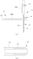
- Fig. 6 shows the distal end 116 of the flexible tube 110 of the catheter 11, 11'.
- the flexible tube 110 comprises a reinforcement 112 at its distal end 113.
- the reinforcement 112 is cylindrical in this example.
- the reinforcement 112 supports the flexible tube 110 against pressure of the membrane 22 of the port 2 after removal of the cannula 10.
- the reinforcement 112 is made of a ceramics material, an elastically bendable metal or a plastics material being more rigid than the plastics material of the flexible tube 110.
- the reinforcement 112 may be made of Teflon.
- Figs. 7A and 7B show two possible protection elements 16, 16' for the port cannula system 1.
- Each of the protection elements 16, 16' may be mounted on or in the body 114, e.g., as described above with reference to Fig. 5 .
- each of the protection elements 16, 16' is made of metal, such as a spring steel.
- the respective protection elements 16, 16' are made in one piece.
- the protection elements 16, 16' are made of (flat) sheet material which is bent several times.
- Each of the protection elements 16, 16' is formed as a needle safety clip.
- each of the protection elements 16, 16' comprises at least one clamp element 161, here two clamp elements 161, and a needle guide 160, 160'.
- the needle guide 160, 160' prevents a form-lock section 101 of the cannula 10 to pass through the needle guide 160, 160'.
- a curved portion of the cannula 10 on or adjacent the tip 100 forms the form-lock section 101.
- the needle guide 160, 160' also prevents a tilting of the protection element 16, 16' with respect to the cannula 10.
- the curved portion of the cannula 10 interacts with the needle guide 160, 160' so that the respective protection element 16, 16' is pulled off from the body 114 together with the cannula 10.
- the respective protection element 16, 16' houses the cannula 10 tip 100.
- the clamp elements 161 project over the cannula 10 tip 100 and, thereby, can prevent needlestick injuries.
- the clamp elements 161 cross each other.
- the needle guide 160 of the protection element 16 of Fig. 7A comprises two guiding sections that each are in contact with the needle 11 and are spaced apart from one another. Between the two guiding sections the cannula 10 is exposed.
- the needle guide 160' of the protection element 16' of Fig. 7B comprises one guiding section forming a cylindrical area of contact with the cannula 10 wherein, in the present example, the cylinder length is larger than the cylinder diameter.
Landscapes
- Health & Medical Sciences (AREA)
- Heart & Thoracic Surgery (AREA)
- Hematology (AREA)
- Engineering & Computer Science (AREA)
- Anesthesiology (AREA)
- Biomedical Technology (AREA)
- Life Sciences & Earth Sciences (AREA)
- Animal Behavior & Ethology (AREA)
- General Health & Medical Sciences (AREA)
- Public Health (AREA)
- Veterinary Medicine (AREA)
- Vascular Medicine (AREA)
- Pulmonology (AREA)
- Dermatology (AREA)
- Infusion, Injection, And Reservoir Apparatuses (AREA)
Abstract
A port cannula system (1) for puncturing a port (2) comprises: a cannula (10) and a catheter (11; 11') having a flexible tube (110) surrounding the cannula (10). The port cannula system (1) further comprises a fixation element (12; 12') adapted to fix the catheter (11; 11) to the skin (3) of a person such that the fixation element (12; 12') is arranged between the catheter (11; 11') and the skin (3).
Description
- The invention relates to a port cannula system for puncturing a port.
- Port cannulas are used for puncturing implanted port catheters. An implanted port catheter, in short also referred to as port, is arranged under the skin of a patient and typically defines a volume covered by a membrane. The volume of the port is connected to a catheter that opens into a vessel or other treatment site. To administer a liquid into the port, a port cannula with a needle is used. The needle is pressed through the skin of the patient and through the membrane into the volume so that the liquid can be filled into the volume of the port and, thereby, administered to the patient.
- Such a port is described in
US 2013/0226103 A1 . - Depending on weight and size of the patient, the thickness of the tissue covering the implanted port may differ strongly. Therefore, commonly a cannula with a correct needle length must be selected before the application. The needle length is selected to be just long enough to reach the volume of the port and at the same time allow a connecting piece of the port cannula to be in contact with the patient's skin to be secured thereto.
- Due to the wide range of weights and sizes of the various patients, hospitals typically have to store a significant number of different needle lengths, e.g., six different lengths. Since regularly also different needle diameters may be applied, e.g., three different diameters, a large number of different port cannulas may have to be kept in a storeroom. In addition, the manufacturing of the port cannulas is complex, because the various different combinations of needle diameters and lengths need to be made.
-
US 5,135,502 A proposes a solid introducer for a catheter to a port with the same disadvantages as described above.DE 697 30 513 T2 describes a security-catheter arrangement which is applicable for different weights and sizes of the various patients. However, these two solutions are relatively inconvenient in use and, therefore, both have not been accepted in wider practice. - It is an object of the instant invention to provide an improved port cannula system.
- This object is achieved by means of a port cannula system comprising the features of
claim 1. - Accordingly, a port cannula system for puncturing a port comprises a cannula and a catheter having a flexible tube surrounding the cannula. The port cannula system further comprises a fixation element. The fixation element is adapted to fix the catheter to the skin of a person such that the fixation element is arranged between the catheter and the skin.
- This is based on the finding that known solutions are neither convenient for healthcare personnel in the application nor comfortable for the patient. The fixation element of the proposed solution both provides a reference and an aid for correctly applying the catheter to the port at the required depth, as well as a secure and comfortable fixture of the catheter on the skin. Since the tube is flexible, the catheter may be bent so as to extend in parallel to the skin.
- The fixation element may comprise a locking portion for removably locking the catheter to the fixation element. By this, the catheter may be fixed on the skin in a particularly simple and reliable manner.
- The fixation element has a skin-facing side for contacting the skin when the fixation element is fixed to the skin. The locking portion may be arranged on an upper side of the fixation element. The upper side is, e.g., opposite the skin-facing side. As such, the port cannula system can be quickly and easily applied in a secure manner.
- Optionally, the skin-facing side is provided with an adhesive for fixation to the skin. By this, the application can be particularly reliable and simple.
- The locking portion and the catheter may form a snap-in connection. Alternatively or in addition, the locking portion and the catheter may be engageable with one another. Alternatively or in addition, the locking portion and the catheter may comprise a hook-and-loop fastener. These variants allow particularly simple and quick applications.
- The port cannula system may comprise a scale configured to indicate a length of the flexible tube pierced into the skin. This can simplify the application and improve the precision thereof.
- Optionally, the scale is provided on the fixation element, wherein an indicator indicating the length (of the flexible tube pierced into the skin) on the scale is provided on the catheter. Alternatively, the scale may be provided on the flexible tube, wherein an indicator indicating the length (of the flexible tube pierced into the skin) on the scale is provided on the fixation element. This allows to easily adjust the correct length without additional components. For example, the length may be documented and used for another infusion at a later point in time if the patient has not gained or lost weight.
- The catheter may comprise a connector for establishing a fluid connection between the flexible tube and another part, e.g., a connection hose. By this, a simple construction being convenient in use can be provided.
- The port cannula system may further comprise a tip protection element removably arranged at the connector and adapted to cover a tip of the cannula when the cannula is withdrawn from the catheter. This allows to prevent needle-stick injuries.
- The fixation element may comprise a hole. The catheter (more precisely, the flexible tube thereof) may extend through the hole and/or may be adapted to extend through the hole. This allows a reliable functionality and a protected puncture site. Furthermore, the position of the flexible tube is secured with respect to the puncture site and port via the fixation element. Unintentional removal of the flexible tube, for example upon movement of the patient is prevented. The fixation element comprises for example a plate. In the state fixed to the skin, the plate is in planar abutment with the skin. The plate is, e.g., made of a firm, yet flexible material such as silicone to be comfortable to wear for the patient. A hole is formed in the plate. The flexible tube of the catheter extends through the hole, into the skin and inside the port under the skin.
- The flexible tube may comprise a plastics material. By this, a reliable function can be provided. The cannula may be made of a metal, e.g., steel.
- Optionally, the flexible tube comprises a reinforcement, e.g., at its distal end. The reinforcement may have a larger stiffness than other portions of the flexible tube. By this, insertion of the flexible tube into the port membrane may be simplified. In addition, the reinforcement can support the flexible tube against elastic forces of the port membrane. This allows to avoid that the membrane squeezes the flexible tube together. In addition, a softer material can be used for the flexible tube.
- The reinforcement may comprise, or consist of, a ceramics material, an elastically bendable metal or a plastics material being more rigid than the plastics material of the flexible tube. This allows to further improve the reinforcement.
- The distal end of the flexible tube may be tapered, e.g., sharpened. This allows to facilitate the application of the catheter.
- The port cannula system may further comprise an implantable port comprising a membrane adapted to be punctured by the cannula and the flexible tube surrounding the cannula.
- The idea underlying the invention shall subsequently be described in more detail by referring to the embodiments shown in the figures. Herein:
- Fig. 1
- shows an implanted port catheter;
- Fig. 2
- shows a catheter and a fixation element of a port cannula system, the catheter being in connection with the implanted port catheter according to
Fig. 1 ; - Fig. 3A
- shows the port catheter system with the catheter and the fixation element according to
Fig. 2 as well as a cannula arranged within the catheter; - Fig. 3B
- shows the catheter and the fixation element according to
Fig. 3 after removal of the cannula; - Fig. 3C
- shows the catheter and the fixation element according to
Fig. 3 after fixing a body of the catheter to the fixation element; - Fig. 4
- shows a cross section of the catheter and the fixation element according to
Fig. 3C ; - Fig. 5
- shows a port catheter system with a cannula, a catheter and a fixation element;
- Fig. 6
- shows a distal end of the catheter according to
Figs. 2 and5 ; and - Figs. 7A and 7B
- show optional protection elements for the cannula.
- Subsequently, port cannula systems for puncturing a port shall be described. The embodiments described herein shall not be construed as limiting for the scope of the invention.
-
Fig. 1 shows an implantable port catheter, in the following referred to asport 2. InFig. 1 , theport 2 is shown in a state implanted under theskin 3 of a person. Theport 2 comprises a housing 20which defines aninterior volume 21. A membrane 22 of theport 2 closes thevolume 21. Thevolume 21 may also be referred to as infusion chamber. Acatheter 23 is attached to thehousing 20 and in fluid connection with thevolume 21. Thecatheter 23 establishes a connection of theport 2 to a tissue, for example a vein. In order to give a patient a medicament that is to be administered intravenously, for example, the membrane 22 is pierced via theskin 3 by means of a port cannula. The port cannula establishes the connection between theinfusion chamber volume 21 formed in thehousing 20, e.g., to an infusion bag. As an example, a port catheter like theport 2 shown inFig. 1 can have an implantation time of up to 5 years. Accordingly, theport 2 may be punctured often by a port cannula. The membrane 22 is made of a suitable material, e.g., silicone. -
Figs. 2-4 illustrate aport cannula system 1 for puncturing theport 2 ofFig. 1 . - The
port cannula system 1 comprises acannula 10, acatheter 11 device with aflexible tube 110 surrounding thecannula 10, and afixation element 12 adapted to fix thecatheter 11 to theskin 3 of a person such that thefixation element 12 is arranged between thecatheter 11 and theskin 3. -
Fig. 2 shows thefixation element 12 in a state adhered to theskin 3, wherein abody 114 of thecatheter 11 is mounted on thefixation element 12. Theflexible tube 110 is mounted on thebody 114. Thefixation element 12 comprises aplate 127 which, in the present example, consists of silicone which allows a comfortable use by its flexibility. In the state fixed to theskin 3 as shown inFig. 2 , theplate 127 is in planar abutment with theskin 3. A hole 126 is formed in theplate 127. Theflexible tube 110 of thecatheter 11 extends through the hole 126, into theskin 3 and inside theport 2 under theskin 3. - Before turning back to
Fig. 2 , reference is now made toFigs. 3A-3C . -
Fig. 3A shows a side view of theport cannula system 1. Thecannula 10 is arranged in theflexible tube 110 of thecatheter 11. As such, therigid cannula 10 stiffens theflexible tube 110. Atip 100 of thecannula 10 projects from theflexible tube 110. Thetip 100 is sharpened. Adistal end 113 of thecatheter 11 is arranged adjacent thecannula 10tip 100. Thedistal end 113 of thecatheter 11 is tapered. Thus, thecatheter 11 with thecannula 10 can be punctured into theskin 3 and into theport 2 under theskin 3. When puncturing theport 2, thefixation element 12 may be laid on theskin 3. Alternatively, it may held upwards for using ascale 13 provided on thefixation element 12, seeFig. 2 . Thebody 114 of thecatheter 11 comprises anindicator 14, in this example a line. Theindicator 14 indicates the puncturing depth on thescale 13. -
Figs. 2-4 show that thefixation element 12 has a skin-facingside 121 for contacting theskin 3 when thefixation element 12 is fixed to theskin 3, and anupper side 122 opposite the skin-facingside 121. The skin-facingside 121 and theupper side 122 extend in parallel to one another. The skin-facingside 121 and theupper side 122 are the two large sides of theplate 127. On the skin-facingside 121, an adhesive 123 is disposed. The adhesive 123 serves to adhere thefixation element 12 to the skin. - Further, the
fixation element 12 comprises a lockingportion 120 for removably locking thecatheter 11 to thefixation element 12. The lockingportion 120 is arranged on theupper side 122 of thefixation element 12. - As soon as the
catheter 11 has been pierced deep enough into theport 2 under theskin 3, thecannula 10 may be removed. Thecannula 10 comprises abody 102, which protrudes from thebody 114 of thecatheter 11. For removing thecannula 10, thebody 102 can be used to manually pull thecannula 10 out of the catheter. -
Fig. 3B shows thecatheter 11 and thefixation element 12 without thecannula 10. Therefore, after removal of thecannula 10, theflexible tube 110 can be easily bent. Thus, after removing thecannula 10, theflexible tube 110 can be bent so as to fix thebody 114 of thecatheter 11 on the lockingportion 120 of thefixation element 12. - As shown in
Fig. 3C , thebody 114 then extends substantially perpendicular to the part of the flexible tube punctured into theskin 3 andport 2. - The
scale 13 is provided on theupper side 122 of theplate 127 and facilitates the adjustment and inspection of the correct puncturing depth. The scale provides an indication in cm and mm. - In the configuration shown in
Figs. 2 and3C , the point on theskin 3 where thecatheter 11 enters theskin 3 is covered by thefixation element 12 thefixation element 12 is rigid. For example, thefixation element 12 is made of plastics. Therefore, thefixation element 12 protects the puncture site. Further, since thebody 114 of thecatheter 11 is fixedly retained and supported on thefixation element 12, it is laid flat on theskin 3, so that it does not protrude much from theskin 3. This makes it both well protected and securely fixed on theskin 3, as well as comfortable for the patient. - As shown in
Fig. 4 , the lockingportion 120 of this example comprises two sidewalls between which thebody 114 of thecatheter 11 can be placed. The lockingportion 120 forms a snap-inconnection 124 together with thebody 114. In the present example, the sidewalls of the lockingportion 120 comprise inwardly facing protrusions below which thebody 114 may be snapped in. - When fixed to the
fixation element 12, thebody 114 of thecatheter 11 extends along the length of theplate 127 of thefixation element 12. - The
body 114 of thecatheter 11 also forms aconnector 111 for connection to a fluid supply. As shown inFig. 2 , aconnector 150 of aconnection hose 15 can be brought in fluid connection to theconnector 111 of thecatheter 11. In this example, theconnection hose 15 is provided with an NAC or Luer lock 17 for connection with a supply, such as an infusion pump or the like. - The
fixation element 12 also facilitates removal of thecatheter 11, because thecatheter 11 may be pulled while pushing against thefixation element 12. -
Fig. 5 shows another option for fixing the catheter 11' body to the fixation element 12', namely, using two hook-and-loop fastener loop fastener 125A is fixed to the catheter 11' body, the other part of the hook-and-loop fastener 125B is fixed to the fixation element 12', namely to the upper side of theplate 127 thereof. - Further, according to
Fig. 5 , a scale 13' is provided on theflexible tube 110, wherein an indicator 14' indicating the puncturing length on the scale 13' is provided on the fixation element 12'. - Furthermore, a
protection element 16 as described below with reference toFig. 7A (alternatively in accordance withFig. 7B ) is arranged at (e.g., in) theconnector 111 and/or at thebody 114 of thecatheter 11, and adapted to cover thetip 100 of thecannula 10 when thecannula 10 is withdrawn from thecatheter 11. -
Fig. 6 shows the distal end 116 of theflexible tube 110 of thecatheter 11, 11'. As shown, theflexible tube 110 comprises areinforcement 112 at itsdistal end 113. Thereinforcement 112 is cylindrical in this example. Thereinforcement 112 supports theflexible tube 110 against pressure of the membrane 22 of theport 2 after removal of thecannula 10. - The
reinforcement 112 is made of a ceramics material, an elastically bendable metal or a plastics material being more rigid than the plastics material of theflexible tube 110. As an example, thereinforcement 112 may be made of Teflon. -
Figs. 7A and 7B show twopossible protection elements 16, 16' for theport cannula system 1. Each of theprotection elements 16, 16' may be mounted on or in thebody 114, e.g., as described above with reference toFig. 5 . - In the present examples, each of the
protection elements 16, 16' is made of metal, such as a spring steel. Here, therespective protection elements 16, 16' are made in one piece. Further, theprotection elements 16, 16' are made of (flat) sheet material which is bent several times. Each of theprotection elements 16, 16' is formed as a needle safety clip. Further, each of theprotection elements 16, 16' comprises at least oneclamp element 161, here twoclamp elements 161, and aneedle guide 160, 160'. By means of theneedle guide 160, 160', therespective protection element 16, 16' is slidable along thecannula 10. However, theneedle guide 160, 160' prevents a form-lock section 101 of thecannula 10 to pass through theneedle guide 160, 160'. In this example, a curved portion of thecannula 10 on or adjacent thetip 100 forms the form-lock section 101. Theneedle guide 160, 160' also prevents a tilting of theprotection element 16, 16' with respect to thecannula 10. - When pulling the
cannula 10 out of thebody 114, the curved portion of thecannula 10 interacts with theneedle guide 160, 160' so that therespective protection element 16, 16' is pulled off from thebody 114 together with thecannula 10. As such, therespective protection element 16, 16' houses thecannula 10tip 100. Theclamp elements 161 project over thecannula 10tip 100 and, thereby, can prevent needlestick injuries. Theclamp elements 161 cross each other. - The
needle guide 160 of theprotection element 16 ofFig. 7A comprises two guiding sections that each are in contact with theneedle 11 and are spaced apart from one another. Between the two guiding sections thecannula 10 is exposed. - The needle guide 160' of the protection element 16' of
Fig. 7B comprises one guiding section forming a cylindrical area of contact with thecannula 10 wherein, in the present example, the cylinder length is larger than the cylinder diameter. - The idea of the invention is not limited to the embodiments described above but may be implemented in a different fashion.
-
- 1
- Port cannula system
- 10
- Cannula
- 100
- Tip
- 101
- Form-lock section
- 102
- Body
- 11; 11'
- Catheter
- 110
- Flexible tube
- 111
- Connector
- 112
- Reinforcement
- 113
- Distal end
- 114
- Body
- 12; 12'
- Fixation element
- 120
- Locking portion
- 121
- Skin-facing side
- 122
- Upper side
- 123
- Adhesive
- 124
- Snap-in connection
- 125A, 125B
- Hook-and-loop fastener
- 126
- Hole
- 127
- Plate
- 13; 13'
- Scale
- 14; 14'
- Indicator
- 15
- Connection hose
- 150
- Connector
- 16; 16'
- Protection element
- 160; 160'
- Needle guide
- 161
- Clamp element
- 17
- Luer lock
- 2
- Port
- 20
- Housing
- 21
- Volume
- 22
- Membrane
- 23
- Catheter
- 3
- Skin
Claims (15)
- A port cannula system (1) for puncturing a port (2), the port cannula system (1) comprising:- a cannula (10) and- a catheter (11; 11') having a flexible tube (110) surrounding the cannula (10),characterized by- a fixation element (12; 12') adapted to fix the catheter (11; 11') to the skin (3) of a person such that the fixation element (12; 12') is arranged between the catheter (11; 11') and the skin (3).
- The port cannula system (1) according to claim 1, characterized in that the fixation element (12; 12') comprises a locking portion (120) for removably locking the catheter (11; 11') to the fixation element (12; 12').
- The port cannula system (1) according to claim 2, characterized in that the fixation element (12; 12') has a skin-facing side (121) for contacting the skin (3) when the fixation element (12; 12') is fixed to the skin (3), the locking portion (120) being arranged on an upper side (122) of the fixation element (12; 12') opposite the skin-facing side (121).
- The port cannula system (1) according to claim 3, characterized in that the skin-facing side (121) is provided with an adhesive (123) for fixation to the skin (3).
- The port cannula system (1) according to any of claims 2 to 4, characterized in that the locking portion (120) and the catheter (11; 11') form a snap-in connection (124), are engageable with one another and/or comprise a hook-and-loop fastener (125A, 125B).
- The port cannula system (1) according to any of the preceding claims, characterized by a scale (13; 13') configured to indicate a length of the flexible tube (110) pierced into the skin (3).
- The port cannula system (1) according to claim 6, characterized in that the scale (13) is provided on the fixation element (12; 12'), wherein an indicator (14) indicating the length on the scale (13) is provided on the catheter (11) or that the scale (13') is provided on the flexible tube (110), wherein an indicator (14') indicating the length on the scale (13') is provided on the fixation element (12').
- The port cannula system (1) according to any of the preceding claims, characterized in that the catheter (11; 11') comprises a connector (111) for establishing a fluid connection between the flexible tube (110) and a connection hose (15).
- The port cannula system (1) according to claim 8, characterized by a tip protection element (16; 16') arranged at the connector (111) and adapted to cover a tip (100) of the cannula (10) when the cannula (10) is withdrawn from the catheter (11; 11').
- The port cannula system (1) according to any of the preceding claims, characterized in that the fixation element (12; 12') comprises a hole (126), wherein the catheter (11; 11') extends through the hole (126).
- The port cannula system (1) according to any of the preceding claims, characterized in that the flexible tube (110) comprises a plastics material.
- The port cannula system (1) according to any of the preceding claims, characterized in that the flexible tube (110) comprises a reinforcement (112) at its distal end (113).
- The port cannula system (1) according to claim 12, characterized in that the reinforcement (112) comprises, or consists of, a ceramics material, an elastically bendable metal or a plastics material being more rigid than the plastics material of the flexible tube (110).
- The port cannula system (1) according to any of the preceding claims, characterized in that the distal end (113) of the flexible tube (110) is tapered.
- The port cannula system (1) according to any of the preceding claims, characterized by an implantable port (2) comprising a membrane (22) adapted to be punctured by the cannula (10) and the flexible tube (110) surrounding the cannula (10).
Priority Applications (1)
| Application Number | Priority Date | Filing Date | Title |
|---|---|---|---|
| EP23162908.0A EP4434561A1 (en) | 2023-03-20 | 2023-03-20 | Port cannula system with a flexible tube |
Applications Claiming Priority (1)
| Application Number | Priority Date | Filing Date | Title |
|---|---|---|---|
| EP23162908.0A EP4434561A1 (en) | 2023-03-20 | 2023-03-20 | Port cannula system with a flexible tube |
Publications (1)
| Publication Number | Publication Date |
|---|---|
| EP4434561A1 true EP4434561A1 (en) | 2024-09-25 |
Family
ID=85704945
Family Applications (1)
| Application Number | Title | Priority Date | Filing Date |
|---|---|---|---|
| EP23162908.0A Withdrawn EP4434561A1 (en) | 2023-03-20 | 2023-03-20 | Port cannula system with a flexible tube |
Country Status (1)
| Country | Link |
|---|---|
| EP (1) | EP4434561A1 (en) |
Citations (7)
| Publication number | Priority date | Publication date | Assignee | Title |
|---|---|---|---|---|
| US4760847A (en) * | 1986-08-18 | 1988-08-02 | Vincent Vaillancourt | Depth measuring device |
| US5135502A (en) | 1987-12-03 | 1992-08-04 | Medfusion Inc. | Solid introducer for catheter to a port and method of use |
| DE69730513T2 (en) | 1996-10-25 | 2005-09-29 | ACT Medical, Inc., Newton | SUBCUTANEOUS SAFETY CATHETER ARRANGEMENT |
| US20060253076A1 (en) * | 2005-04-27 | 2006-11-09 | C.R. Bard, Inc. | Infusion apparatuses and methods of use |
| US20070191773A1 (en) * | 2006-02-16 | 2007-08-16 | Animas Corporation | Low profile infusion set |
| US20130226103A1 (en) | 2012-01-09 | 2013-08-29 | Fresenius Kabi Deutschland Gmbh | Port cannula for the puncturing of port catheters |
| WO2022158888A1 (en) * | 2021-01-21 | 2022-07-28 | 인제대학교 산학협력단 | Fixing piece for medical insert to be inserted into perforated portion of human body |
-
2023
- 2023-03-20 EP EP23162908.0A patent/EP4434561A1/en not_active Withdrawn
Patent Citations (7)
| Publication number | Priority date | Publication date | Assignee | Title |
|---|---|---|---|---|
| US4760847A (en) * | 1986-08-18 | 1988-08-02 | Vincent Vaillancourt | Depth measuring device |
| US5135502A (en) | 1987-12-03 | 1992-08-04 | Medfusion Inc. | Solid introducer for catheter to a port and method of use |
| DE69730513T2 (en) | 1996-10-25 | 2005-09-29 | ACT Medical, Inc., Newton | SUBCUTANEOUS SAFETY CATHETER ARRANGEMENT |
| US20060253076A1 (en) * | 2005-04-27 | 2006-11-09 | C.R. Bard, Inc. | Infusion apparatuses and methods of use |
| US20070191773A1 (en) * | 2006-02-16 | 2007-08-16 | Animas Corporation | Low profile infusion set |
| US20130226103A1 (en) | 2012-01-09 | 2013-08-29 | Fresenius Kabi Deutschland Gmbh | Port cannula for the puncturing of port catheters |
| WO2022158888A1 (en) * | 2021-01-21 | 2022-07-28 | 인제대학교 산학협력단 | Fixing piece for medical insert to be inserted into perforated portion of human body |
Similar Documents
| Publication | Publication Date | Title |
|---|---|---|
| US12508050B2 (en) | Inserter for simultaneous insertion of multiple transcutaneous parts | |
| US10729845B2 (en) | Angled inserter for drug infusion | |
| US5413562A (en) | Stabilizing fitting for an intravenous catheter or syringe | |
| EP2836254B1 (en) | Manual pressure activated application mechanism | |
| US9399094B2 (en) | Assembly comprising skin-mountable device and packaging therefore | |
| CN100579598C (en) | Breathable skin-mountable device | |
| EP4364779A3 (en) | Guidewire advancement and blood flashback systems for a medical device insertion system | |
| JP2000504973A (en) | Safe hypodermic catheter assembly | |
| KR20070042885A (en) | Safety injector | |
| JPH09512199A (en) | Percutaneous sensor insertion set | |
| KR20070082516A (en) | Low profile injection set | |
| EP3849652B1 (en) | Port for a catheter for subcutaneous implantation into a patient | |
| JP2021518224A (en) | Indwelling cannula | |
| EP3679970B1 (en) | Cradle for an infusion pump unit | |
| CN112714660A (en) | Port for a catheter subcutaneously implanted in a patient | |
| WO2004022139A1 (en) | Mounting platform for skin piercing medical devices | |
| WO2024133185A1 (en) | Port cannula with bendable needle | |
| US8882715B2 (en) | Catheterization device and method | |
| HK40059601A (en) | Cradle for an infusion pump unit |
Legal Events
| Date | Code | Title | Description |
|---|---|---|---|
| PUAI | Public reference made under article 153(3) epc to a published international application that has entered the european phase |
Free format text: ORIGINAL CODE: 0009012 |
|
| STAA | Information on the status of an ep patent application or granted ep patent |
Free format text: STATUS: THE APPLICATION HAS BEEN PUBLISHED |
|
| AK | Designated contracting states |
Kind code of ref document: A1 Designated state(s): AL AT BE BG CH CY CZ DE DK EE ES FI FR GB GR HR HU IE IS IT LI LT LU LV MC ME MK MT NL NO PL PT RO RS SE SI SK SM TR |
|
| STAA | Information on the status of an ep patent application or granted ep patent |
Free format text: STATUS: THE APPLICATION HAS BEEN WITHDRAWN |
|
| 18W | Application withdrawn |
Effective date: 20240927 |