EP4434469A1 - Wireless probe - Google Patents
Wireless probe Download PDFInfo
- Publication number
- EP4434469A1 EP4434469A1 EP24152322.4A EP24152322A EP4434469A1 EP 4434469 A1 EP4434469 A1 EP 4434469A1 EP 24152322 A EP24152322 A EP 24152322A EP 4434469 A1 EP4434469 A1 EP 4434469A1
- Authority
- EP
- European Patent Office
- Prior art keywords
- battery
- electrode
- housing
- wireless probe
- transducer
- Prior art date
- Legal status (The legal status is an assumption and is not a legal conclusion. Google has not performed a legal analysis and makes no representation as to the accuracy of the status listed.)
- Granted
Links
Images















Classifications
-
- A—HUMAN NECESSITIES
- A61—MEDICAL OR VETERINARY SCIENCE; HYGIENE
- A61B—DIAGNOSIS; SURGERY; IDENTIFICATION
- A61B8/00—Diagnosis using ultrasonic, sonic or infrasonic waves
- A61B8/44—Constructional features of the ultrasonic, sonic or infrasonic diagnostic device
- A61B8/4444—Constructional features of the ultrasonic, sonic or infrasonic diagnostic device related to the probe
-
- A—HUMAN NECESSITIES
- A61—MEDICAL OR VETERINARY SCIENCE; HYGIENE
- A61B—DIAGNOSIS; SURGERY; IDENTIFICATION
- A61B8/00—Diagnosis using ultrasonic, sonic or infrasonic waves
- A61B8/44—Constructional features of the ultrasonic, sonic or infrasonic diagnostic device
- A61B8/4444—Constructional features of the ultrasonic, sonic or infrasonic diagnostic device related to the probe
- A61B8/4472—Wireless probes
-
- A—HUMAN NECESSITIES
- A61—MEDICAL OR VETERINARY SCIENCE; HYGIENE
- A61B—DIAGNOSIS; SURGERY; IDENTIFICATION
- A61B8/00—Diagnosis using ultrasonic, sonic or infrasonic waves
- A61B8/44—Constructional features of the ultrasonic, sonic or infrasonic diagnostic device
- A61B8/4477—Constructional features of the ultrasonic, sonic or infrasonic diagnostic device using several separate ultrasound transducers or probes
-
- A—HUMAN NECESSITIES
- A61—MEDICAL OR VETERINARY SCIENCE; HYGIENE
- A61B—DIAGNOSIS; SURGERY; IDENTIFICATION
- A61B8/00—Diagnosis using ultrasonic, sonic or infrasonic waves
- A61B8/56—Details of data transmission or power supply
-
- G—PHYSICS
- G01—MEASURING; TESTING
- G01S—RADIO DIRECTION-FINDING; RADIO NAVIGATION; DETERMINING DISTANCE OR VELOCITY BY USE OF RADIO WAVES; LOCATING OR PRESENCE-DETECTING BY USE OF THE REFLECTION OR RERADIATION OF RADIO WAVES; ANALOGOUS ARRANGEMENTS USING OTHER WAVES
- G01S7/00—Details of systems according to groups G01S13/00, G01S15/00, G01S17/00
- G01S7/52—Details of systems according to groups G01S13/00, G01S15/00, G01S17/00 of systems according to group G01S15/00
- G01S7/52017—Details of systems according to groups G01S13/00, G01S15/00, G01S17/00 of systems according to group G01S15/00 particularly adapted to short-range imaging
- G01S7/52079—Constructional features
-
- A—HUMAN NECESSITIES
- A61—MEDICAL OR VETERINARY SCIENCE; HYGIENE
- A61B—DIAGNOSIS; SURGERY; IDENTIFICATION
- A61B8/00—Diagnosis using ultrasonic, sonic or infrasonic waves
- A61B8/44—Constructional features of the ultrasonic, sonic or infrasonic diagnostic device
- A61B8/4483—Constructional features of the ultrasonic, sonic or infrasonic diagnostic device characterised by features of the ultrasound transducer
- A61B8/4494—Constructional features of the ultrasonic, sonic or infrasonic diagnostic device characterised by features of the ultrasound transducer characterised by the arrangement of the transducer elements
-
- Y—GENERAL TAGGING OF NEW TECHNOLOGICAL DEVELOPMENTS; GENERAL TAGGING OF CROSS-SECTIONAL TECHNOLOGIES SPANNING OVER SEVERAL SECTIONS OF THE IPC; TECHNICAL SUBJECTS COVERED BY FORMER USPC CROSS-REFERENCE ART COLLECTIONS [XRACs] AND DIGESTS
- Y02—TECHNOLOGIES OR APPLICATIONS FOR MITIGATION OR ADAPTATION AGAINST CLIMATE CHANGE
- Y02E—REDUCTION OF GREENHOUSE GAS [GHG] EMISSIONS, RELATED TO ENERGY GENERATION, TRANSMISSION OR DISTRIBUTION
- Y02E60/00—Enabling technologies; Technologies with a potential or indirect contribution to GHG emissions mitigation
- Y02E60/10—Energy storage using batteries
Definitions
- the disclosure provides a wireless probe including a battery that may be separated and assembled.
- An ultrasound diagnostic apparatus irradiates an ultrasound signal generated from a transducer of a probe to an object, receives information from a signal reflected from the object, and obtains at least one image of a region (e.g., soft tissue or blood flow) inside the object.
- a region e.g., soft tissue or blood flow
- a wireless probe connected to an external device for example, a main body, through a wireless network is being developed so that a user may operate the probe without spatial constraints.
- the wireless probe does not include a separate wiring for receiving power from the outside, and may receive power by using an internal battery.
- a wireless probe according to an embodiment may provide a structure in which a battery may be separated and assembled to be located between a transducer and a circuit board.
- a wireless probe according to an embodiment may allow a battery to be inserted into a housing along a longitudinal direction of the battery, thereby facilitating separation and assembly of the battery and improving waterproof performance.
- a wireless probe includes
- the housing may include an outer housing forming an exterior and including an opening formed at one end in the second direction, a housing cap forming an exterior and configured to open and close the opening, and a battery accommodating unit located inside the outer housing and accommodating the battery inserted through the opening therein.
- the battery accommodating unit may be connected to the opening, has a cross-sectional shape corresponding to a cross-sectional shape of the battery, and extends along the second direction.
- the wireless probe may further include at least one flexible circuit unit electrically connecting the circuit board to the first transducer and formed to bypass the battery accommodating unit.
- the battery may include a first electrode portion and a second electrode portion located adjacent to each other at the front in an insertion direction.
- the battery may include a battery body including a first electrode and a second electrode having different polarities and provided at both ends in a longitudinal direction, and an electrode adjusting assembly exposing the first electrode to outside to form the first electrode portion, covering the second electrode, and electrically connected to the second electrode to form the second electrode portion adjacent to the first electrode portion.
- the electrode adjusting assembly may include an inner insulator configured to surround an outer surface of the battery body and expose the first electrode and the second electrode through both ends of the inner insulator, an electrode moving body including an electrode contact portion contacting the second electrode exposed through the inner insulator, the second electrode portion located at a position spaced apart from the electrode contact portion, and an extending portion electrically connecting the electrode contact portion to the second electrode portion, and an outer insulator configured to surround an outer surface of the inner insulator, cover the electrode contact portion and the extending portion of the electrode moving body, and expose the second electrode portion.
- the battery accommodating unit may include a first electrode terminal for electrical contact with the first electrode portion of the battery, and a second electrode terminal for electrical contact with the second electrode portion of the battery, wherein directions of the first electrode terminal and the second electrode terminal are perpendicular to each other.
- An outer diameter of the second electrode portion may be less than an outer diameter of the outer insulator so that the second electrode portion forms a concave portion of the battery.
- a distance between the second electrode portion and the opening along the second direction may be greater than a distance between the second electrode and the opening along the second direction.
- a difference between a length of the first transducer along the second direction and a length of the battery along the second direction may be 20% or less of the length of the battery along the second direction.
- the housing cap may have an open position for opening the opening and a closed position for closing the opening, wherein the housing cap includes a locking member configured to maintain the closed position.
- the wireless probe may further include a manipulation member configured to facilitate release of a locked state by the locking member.
- the wireless probe may further include a sealing member located on at least one of the outer housing and the housing cap to prevent penetration of water between the outer housing and the housing cap.
- the wireless probe may further include a sensor configured to detect whether the housing cap is at an open position, wherein an operation of the first transducer is controlled based on a detection result of the sensor.
- the wireless probe may further include a second transducer located at the other end of the housing,
- a width of the first transducer in the second direction is different from a width of the second transducer in the second direction.
- module denotes those that may be embodied by software or hardware. According to embodiments, a plurality of modules, parts, or portions may be embodied by a single unit or element, or a single part or portion may include a plurality of elements.
- an image may include a medical image obtained by a medical imaging apparatus such as magnetic resonance imaging (MRI) apparatus, a computed tomography (CT) apparatus, an ultrasound imaging apparatus, or an X-ray imaging apparatus.
- MRI magnetic resonance imaging
- CT computed tomography
- ultrasound imaging apparatus an ultrasound imaging apparatus
- X-ray imaging apparatus an X-ray imaging apparatus
- an "object” may be a target to be imaged and may include a human, an animal, or a part of a human or animal.
- an object may include a body part (e.g., an organ) or a phantom.
- an "ultrasound image” refers to an image of an object processed based on an ultrasound signal transmitted to the object and reflected therefrom.
- FIG. 1 is a block diagram illustrating a configuration of an ultrasound diagnostic apparatus 100, according to an embodiment.
- the ultrasound diagnostic apparatus 100 may include a wireless probe 20 and an ultrasound imaging apparatus 40.
- the wireless probe 20 may include a transmission module 113, a transducer 115, a reception module 117, a processor 118, and a communication module 119. Although the wireless probe 20 includes both the transmission module 113 and the reception module 117 in FIG. 1 , according to an implementation type, the wireless probe 20 may include only some of components of the transmission module 113 and the reception module 117 and some of components of the transmission module 113 and the reception module 117 may be included in the ultrasound imaging apparatus 40. Alternatively, the wireless prove 20 may further include an image processor 130.
- the transducer 115 may include a plurality of transducer members.
- the plurality of transducer members may transmit an ultrasound signal to an object 10 according to a transmission signal applied from the transmission module 113.
- the plurality of transducer members may receive an ultrasound signal reflected from the object 10 to form a reception signal.
- the processor 118 controls the transmission module 113 to form a transmission signal to be applied to each of the plurality of transducer members, by considering positions and focal points of the plurality of transducer members.
- the processor 118 controls the reception module 117 to convert a reception signal received from the transducer 115 through analog-to-digital conversion and add digitally converted reception signals by considering positions and focal points of the plurality of transducer members to generate ultrasound data.
- an ultrasound image may be generated by using the generated ultrasound data.
- the communication module 119 may wirelessly transmit the generated ultrasound data or ultrasound image to the ultrasound imaging apparatus 40 through a wireless network. Also, the communication module 119 may receive a control signal and data from the ultrasound imaging apparatus 40.
- the ultrasound diagnostic apparatus 100 may be connected to one or more wireless probes 20 according to an implementation type.
- the ultrasound imaging apparatus 40 may receive the ultrasound data or ultrasound image from the wireless probe 20.
- the ultrasound imaging apparatus 40 may include a processor 120, the image processor 130, a display 140, a memory 150, a communication module 160, and an input interface 170.
- the image processor 130 generates an ultrasound image, by using the ultrasound data received from the wireless probe 20.
- the display 140 may display the ultrasound image received from the wireless probe 20, the ultrasound image generated by the ultrasound imaging apparatus 40, and various information processed by the ultrasound diagnostic apparatus 100.
- the ultrasound diagnostic apparatus 100 may include one or more displays 140 according to an implementation type. Also, the display 140 may include a touch panel or a touchscreen.
- the processor 120 may control an overall operation of the ultrasound diagnostic apparatus 100 and a signal flow between internal elements of the ultrasound diagnostic apparatus 100.
- the processor 120 may perform or control various operations or functions of the ultrasound diagnostic apparatus 100 by executing a program stored in the memory 150. Also, the processor 120 may control an operation of the ultrasound diagnostic apparatus 100 by receiving a control signal from the input interface 170 or an external device.
- the ultrasound imaging apparatus 40 includes the communication module 160, and may be connected to an external device (e.g., a server, a medical device, a portable device (e.g., a smartphone, a tablet PC, or a wearable device)) through the communication module 160.
- an external device e.g., a server, a medical device, a portable device (e.g., a smartphone, a tablet PC, or a wearable device)
- a portable device e.g., a smartphone, a tablet PC, or a wearable device
- the communication module 160 may include one or more elements that enable communication with an external device.
- the communication module 160 may include at least one of a short-range communication module, a wired communication module, and a wireless communication module.
- the communication module 160 may receive a control signal and data from an external device and transmit the received control signal to the processor 120 so that the processor 120 controls the ultrasound diagnostic apparatus 100 according to the received control signal.
- the processor 120 may transmit a control signal to an external device through the communication module 160, to control the external device according to the control signal of the processor.
- the external device may process data of the external device according to the control signal of the processor received through the communication module.
- a program for controlling the ultrasound diagnostic apparatus 100 may be installed in the external device, the program may include instructions for performing some or all of operations of the processor 120.
- the program may be pre-installed in the external device, or a user of the external device may download and install the program from a server that provides an application.
- a recording medium in which the program is stored may be included in the server that provides the application.
- the memory 150 may store various data or programs for driving and controlling the ultrasound diagnostic apparatus 100, input/output ultrasound data, and an ultrasound image.
- the input interface 170 receives the user's input for controlling the ultrasound diagnostic apparatus 100.
- the user's input may include, but is not limited to, an input manipulating a button, a keypad, a mouse, a trackball, a jog switch, or a knop, an input that touches the touch pad or the touchscreen, a voice input, a motion input, or a biometric information input (e.g., iris recognition or fingerprint recognition).
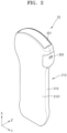
- FIG. 2 is a perspective view illustrating the wireless probe 20, according to an embodiment.
- FIG. 3 is an exploded perspective view illustrating the wireless probe 20, according to an embodiment.
- the wireless probe 20 may include a housing 210, a first transducer 221, a circuit board 230, and a battery 250.
- the housing 210 may have a length in a first direction X.
- the housing 210 may have a width in a second direction Y perpendicular to the first direction X, and may have a thickness in a third direction Z perpendicular to both the first direction X and the second direction Y.
- a length in the first direction X may be greater than a width in the second direction Y
- the width in the second direction Y may be greater than a thickness in the third direction Z.
- a width of the housing 210 in the second direction Y may vary according to a position in the first direction X. For example, a width of one end of the housing 210 in the first direction X may be greater than a width of the other end of the housing 210 in the first direction X.
- the first transducer 221 may be located at one end of the housing 210 in the first direction X.
- the first transducer 221 for transmitting and receiving an ultrasound wave toward a subject may include a plurality of transducer members.
- the plurality of transducer members of the first transducer 221 may be arranged in the second direction Y.
- the plurality of transducer members of the first transducer 221 may be convexly arranged along the second direction Y.
- a second transducer 222 may be located at the other end of the housing 210 in the first direction X.
- the first transducer 221 may be located at one end of the housing 210 in the first direction X, and the second transducer 222 may be located at the other end of the housing 210 in the first direction X.
- a plurality of transducer members of the second transducer 222 may be arranged in the second direction Y.
- the plurality of transducer members of the second transducer 222 may be linearly arranged along the second direction Y.
- a width W1 of the first transducer 221 in the second direction Y may be different from a width W2 of the second transducer 222 in the second direction Y.
- the width W1 of the first transducer 221 in the second direction Y may be greater than the width W2 of the second transducer 222 in the second direction Y.
- the width W2 of the second transducer 222 in the second direction Y may be less than the width W1 of the first transducer 221 in the second direction Y.
- the circuit board 230 may be located inside the housing 210.
- the circuit board 230 may be located inside a handle portion 2101 that is a portion of the housing 210 having a small width in the second direction Y.
- a width of the circuit board 230 in the second direction Y may be less than a width of the handle portion 2101 of the housing 210 in the second direction Y, and may be 80% or more of the width of the handle portion 2101 of the housing 210 in the second direction Y.
- the circuit board 230 may be supported by a board support (not shown) located inside the housing 210.
- the board support may be an element separate from the housing 210, but the disclosure is not limited thereto, and the board support may be integrally formed with the housing 210.
- the circuit board 230 may include a transmission/reception circuit for transmitting/receiving data to/from the first transducer 221 and the second transducer 222.
- the circuit board 230 may include a plurality of sub-circuit boards stacked along the third direction Z.
- the circuit board 230 may include a first sub-circuit board 2301, a second sub-circuit board 2302, and a third sub-circuit board 2303.
- the first sub-circuit board 2301 may include a transmission/reception circuit
- the second sub-circuit board 2302 may include a power circuit
- the third sub-circuit board 2303 may include a control circuit.
- a type of a circuit located on each sub-circuit board is not limited thereto, and may be appropriately changed as necessary.
- the circuit board 230 may be located inside the housing 210, and may be electrically connected to at least one transducer.
- the circuit board 230 may be electrically connected to the first transducer 221, and may be electrically connected to the second transducer 222.
- the first sub-circuit board 2301 may be electrically connected to the first transducer 221, and may be electrically connected to the second transducer 222.
- the first transducer 221 may be electrically connected to the circuit board 230 by at least one first flexible circuit unit 241.
- the plurality of transducer members of the first transducer 221 may be electrically connected to the circuit board 230 by at least one first flexible circuit unit 241.
- the plurality of transducer members of the first transducer 221 may be electrically connected to the circuit board 230 by a plurality of first flexible circuit units 241a and 241b.
- the number of first flexible circuit units 241 is not limited thereto, and may be changed in consideration of the number of transducer members, etc.
- the second transducer 222 may be electrically connected to the circuit board 230 by at least one second flexible circuit unit 242.
- the plurality of transducer members of the second transducer 222 may be electrically connected to the circuit board 230 by at least one second flexible circuit unit 242.
- the plurality of transducer members of the second transducer 222 may be electrically connected to the circuit board 230 by a plurality of second flexible circuit units 242a and 242b.
- the number of second flexible circuit units 242 is not limited thereto, and may be changed in consideration of the number of transducer members, etc.
- the battery 250 may include a standardized battery body 260 (see FIG. 10 ).
- the battery body 260 may have a cylindrical shape.
- the battery body 260 may be a cylindrical battery having a diameter of 18 mm and a length of 65 mm. Because the standardized battery 250 is used as the battery body 260, a user may easily obtain the battery body 260 for supplying power to the wireless probe 20.
- a length L1 of the battery 250 in the second direction Y may correspond to the width W1 of the first transducer 221 in the second direction Y.
- a difference between the width W1 of the first transducer 221 along the second direction Y and the length L1 of the battery 250 along the second direction Y may be 20% or less of the length L1 of the battery 250 along the second direction Y.
- the length L1 of the battery in the second direction Y may be greater than the width W2 of the second transducer 222 in the second direction Y.
- the length L1 of the battery 250 according to the second direction Y may be greater than 1.2 times the width W2 of the second transducer 222 in the second direction Y.
- the wireless probe 20 may perform an ultrasound scan operation by receiving power from the battery 250 located therein, without receiving power from the outside. However, because the wireless probe 20 receives power from the battery 250, the battery 250 needs to be charged or replaced with a charged battery 250 before being completely discharged.
- the wireless probe 20 may provide a structure in which the user may easily replace the battery 250 and waterproof performance may be maintained.
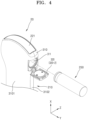
- FIG. 4 is a perspective view illustrating a state where the battery 250 is separated from the wireless probe 20, according to an embodiment.
- FIG. 5 is a perspective view illustrating an internal configuration of the housing 210 in the wireless probe 20 of FIGF. 4.
- the housing 210 of the wireless probe 20 may be configured to allow the battery 250 to be inserted and separated along the second direction Y.
- the battery 250 may be configured to be inserted into and separated from the housing 210 along the second direction Y parallel to a longitudinal direction of the battery 250.
- the housing 210 may include an outer housing 310, a housing cap 320, and a battery accommodating unit 330.
- the outer housing 310 forms the exterior of the wireless probe 20, and includes an opening 311 provided at one end in the second direction Y.
- the opening 311 may have a shape corresponding to a cross-sectional shape of the battery 250.
- a diameter of the opening 311 may correspond to a diameter of the battery 250.
- the outer housing 310 may include a plurality of housing members 3101 and 3102.
- the outer housing 310 may include a plurality of housing members 3101 and 3102 that may be assembled in the third direction Z perpendicular to both the first direction X and the second direction Y.
- the housing cap 320 may form the exterior of the wireless probe 20 along with the outer housing 310, and may be configured to open and close the opening 311. A configuration of the housing cap 320 will be described below with reference to FIG. 12A .
- the battery accommodating unit 330 may be located inside the outer housing 310.
- the battery accommodating unit 330 may be located inside the outer housing 310 to be connected to the opening 311 of the outer housing 310.
- the battery accommodating unit 330 may include a position setting portion 3311 inserted into a position setting portion 3121 of the outer housing 310. Due to the position setting portion 3121 of the outer housing 310 and the position setting portion 3311 of the battery accommodating unit 330, the battery accommodating unit 330 may be maintained at a constant position inside the outer housing 310.
- the battery accommodating unit 330 may have an inner space in which at least a part of the battery 250 inserted through the opening 311 is accommodated.
- the battery accommodating unit 330 may be configured so that the battery 250 is inserted and separated along the second direction Y.
- the battery accommodating unit 330 may extend along the second direction Y.
- the battery accommodating unit 330 may have a cross-sectional shape corresponding to a cross-sectional shape of the battery 250.
- the battery accommodating unit 330 may have a circular cross-sectional shape.
- the battery accommodating unit 330 may guide the battery 250 to move along a certain direction.
- the battery accommodating unit 330 may guide the battery 250 to move in the second direction Y.
- the battery accommodating unit 330 may extend along the second direction Y.
- the battery accommodating unit 330 is an element separate from the outer housing 310 in FIGS. 4 and 5 , the disclosure is not limited thereto.
- the battery accommodating unit 330 and the outer housing 310 may be one element.
- the battery 250 may be inserted into and separated from the right side of the wireless probe 20 in FIGS. 4 and 5 , the disclosure is not limited thereto, and various modifications may be made.
- the battery 250 may be inserted into and separated from the left side of the wireless probe 20.
- FIG. 6 is a perspective view illustrating the battery accommodating unit 330 in the wireless probe 20, according to an embodiment.
- FIG. 7 is a cross-sectional perspective view illustrating the wireless probe 20 of FIG. 6 .
- FIG. 8 is a perspective view illustrating the wireless probe 20, according to an embodiment. In FIGS. 6 to 8 , for convenience of illustration, a part of the housing member 3101 of the outer housing 310 is not shown.
- the battery 250 may be inserted into the battery accommodating unit 330.
- a side surface of the battery 250 may be surrounded by the battery accommodating unit 330.
- the first flexible circuit unit 241 may be located to bypass the battery accommodating unit 330. While the battery 250 is inserted into or separated from the battery accommodating unit 330, the battery accommodating unit 330 may prevent contact between the first flexible circuit unit 241 and the battery 250. Accordingly, damage to the first flexible circuit unit 241 may be prevented.
- a plurality of first flexible circuit units 241 may be provided.
- one first flexible circuit unit 241b from among the plurality of first flexible circuit units 241a and 241b may surround the side portion 331 of the battery accommodating unit 330.
- the other first flexible circuit unit 241a from among the plurality of first flexible circuit units 241a and 241b may be in close contact with the one first flexible circuit unit 241b.
- the other first flexible circuit unit 241a from among the plurality of first flexible circuit units 241a and 241b may surround a part of the first flexible circuit unit 241b.
- the plurality of first flexible circuit units 241a and 241b may be electrically connected to different positions on the circuit board 230.
- the first flexible circuit unit 241b may be connected to one surface, for example, a bottom surface, of the first sub-circuit board 2301, and the other first flexible circuit unit 241a may be connected to the other surface, for example, a top surface, of the first sub-circuit board 2301.
- a position of the first flexible circuit unit 241 in the wireless probe 20 is not limited thereto, and may vary.
- each of the plurality of first flexible circuit units 241a and 241b may surround a part of the side portion 331 of the battery accommodating unit 330.
- the first flexible circuit unit 241b and the other first flexible circuit unit 241a from among the plurality of first flexible circuit units 241a and 241b may be spaced apart from each other and may be connected to the circuit board 230.
- FIG. 9 is a perspective view illustrating the battery 250 used in the wireless probe 20, according to an embodiment.
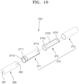
- FIG. 10 is an exploded perspective view illustrating the battery 250 of FIG. 9 .
- FIG. 11 is a cross-sectional view illustrating a part of the wireless probe 20 of FIG. 6 taken along a plane perpendicular to the third direction Z.
- a distance D between the first electrode portion 251 and the second electrode portion 2723 may be less than 1/2 of the length L1 of the battery 250.
- the distance D between the first electrode portion 251 and the second electrode portion 2723 may be less than 1/5 of the length L1 of the battery 250.
- the distance D between the first electrode portion 251 and the second electrode portion 2723 may be less than 1/10 of the length L1 of the battery 250.
- the distance D between the first electrode portion 251 and the second electrode portion 2723 may be 10 mm or less.
- the distance D between the first electrode portion 251 and the second electrode portion 2723 may be 5 mm or less.
- the length L1 of the battery 250 may be the length L1 of the battery 250 along the second direction Y.
- the battery 250 may include the battery body 260 and an electrode adjusting assembly 270 for complementing an electrode position of the battery body 260.
- a first electrode 261 and a second electrode 262 having different polarities may be provided at both ends in the longitudinal direction.
- the first electrode 261 may be located at one end of the battery body 260, and the second electrode 262 may be located at the other end of the battery body 260.
- the first electrode 261 may be a positive electrode
- the second electrode 262 may be a negative electrode
- the first electrode 261 may be a negative electrode
- the second electrode 262 may be a positive electrode.
- the battery body 260 may be a standard battery.
- the battery body 260 may have a shape that is long in the longitudinal direction.
- a length of the battery body 260 may be greater than a diameter (or a width) of the battery body 260.
- a length of the battery body 260 may be greater than twice a diameter of the battery body 260.
- a length of the battery body 260 may be greater than three times a diameter of the battery body 260.
- the battery body 260 may have a cylindrical shape.
- the battery body 260 may be the cylindrical battery 250 having a diameter of 18 mm and a length of 65 mm.
- the electrode adjusting assembly 270 may expose the first electrode 261 of the battery body 260 to the outside to form the first electrode portion 251.
- the first electrode 261 exposed to the outside of the electrode adjusting assembly 270 may function as the first electrode portion 251 of the battery 250.
- the electrode adjusting assembly 270 may cover the second electrode 262 of the battery body 260.
- the electrode adjusting assembly 270 may be electrically connected to the second electrode 262 to form the second electrode portion 2723 adjacent to the first electrode portion 251. Because the electrode adjusting assembly 270 may allow electrical contact through the second electrode portion 2723 adjacent to the first electrode portion 251 while covering the second electrode portion 2723 to prevent external exposure of the second electrode portion 2723, the waterproof performance of the wireless probe 20 may be improved.
- the electrode adjusting assembly 270 may include an inner insulator 271, an electrode moving body 272, and an outer insulator 273.
- the inner insulator 271 may surround a side surface of the battery body 260 and expose the first electrode 261 and the second electrode 262 of the battery body 260 through both ends of the inner insulator 271.
- the inner insulator 271 may have an internal shape corresponding to a side shape of the battery body 260.
- the inner insulator 271 may include an insulating ring 2711 for insulation between the first electrode portion 251 and the second electrode portion 2723.
- the insulating ring 2711 of the inner insulator 271 may have a larger outer diameter than other portions of the inner insulator 271.
- the inner insulator 271 may include first and second openings 2712 and 2713 through which the first electrode 261 and the second electrode 262 of the battery body 260 are exposed.
- the first electrode 261 of the battery body 260 may be exposed through the first opening 2712 of the inner insulator 271, and the second electrode 262 of the battery body 260 may be exposed through the second opening 2713 of the inner insulator 271.
- the electrode moving body 272 may include an electrode contact portion 2721 contacting the second electrode 262 exposed through the inner insulator 271, the second electrode portion 2723 located at a position spaced apart from the electrode contact portion 2721, and an extending portion 2722 electrically connecting the electrode contact portion 2721 to the second electrode portion 2723.
- the electrode moving body 272 may include a conductive material for electrical connection with the second electrode 262.
- the second electrode portion 2723 may have a ring shape surrounding the inner insulator 271.
- the extending portion 2722 may extend in the longitudinal direction of the battery 250.
- a shape of the second electrode portion 2723 and an extending direction of the extending portion 2722 are not limited thereto, and may vary.
- the outer insulator 273 may surround a side surface of the inner insulator 271.
- the extending portion 2722 of the electrode moving body 272 may be located between the outer insulator 273 and the inner insulator 271.
- the outer insulator 273 may cover the electrode contact portion 2721 of the electrode moving body 272.
- the outer insulator 273 may expose the second electrode portion 2723 of the electrode moving body 272.
- the outer insulator 273 may exposed one end of the battery body 260 where the first electrode 261 is formed to the outside, and may cover a side surface of the battery body 260 and the other end of the battery body 260 where the second electrode 262 is formed.
- the battery 250 may be configured so that the second electrode portion 2723 forms a concave portion.
- an outer diameter of the second electrode portion 2723 may be less than an outer diameter of the outer insulator 273.
- an outer diameter of the second electrode portion 2723 may be less than an outer diameter of the insulating ring 2711 of the inner insulator 271.
- the second electrode portion 2723 having a smaller outer diameter than the outer insulator 273 and the inner insulator 271 may form a concave portion of the battery 250.
- the battery 250 may be configured so that an end where the first electrode portion 251 is formed is first inserted into the opening 311 of the outer housing 310.
- a first electrode terminal 341 and a second electrode terminal 342 for electrical connection with the battery 250 may be installed.
- the first electrode terminal 341 may electrically contact the first electrode portion 251 of the battery 250.
- the second electrode terminal 342 may electrically contact the second electrode portion 2723 of the battery 250.
- Directions of the first electrode terminal 341 and the second electrode terminal 342 may be perpendicular to each other.
- the first electrode terminal 341 may be located along a direction parallel to the insertion direction of the battery 250.
- the second electrode terminal 342 may be located along a direction perpendicular to the insertion direction of the battery 250.
- the second electrode terminal 342 may be inserted into the concave portion of the battery 250 where the second electrode portion 2723 is located. Because the second electrode terminal 342 is inserted into the concave portion of the battery 250, an insertion position of the battery 250 electrically connected to the wireless probe 20 may be maintained, and while a user mounts the battery 250, the user may easily recognize whether the battery 250 has reached the insertion position.
- the first and second electrode portions 251 and 2723 of the battery 21560 may be located far from the opening 311 of the outer housing 310.
- a distance between the first and second electrode portions 251 and 2723 of the battery 250 and the opening 311 of the outer housing 310 may increase.
- a distance between the second electrode portion 2723 of the battery and the opening 311 of the outer housing 310 along the second direction Y may be greater than a distance between the second electrode 262 of the battery body 260 and the opening 311 of the outer housing 310 along the second direction Y.
- the waterproof performance of the wireless probe 20 may be improved. For example, even when water penetrates into the opening 311 of the outer housing 310, a distance through which the penetrated water reaches the first and second electrode portions 251 and 2723 of the battery 250 is increased, thereby improving waterproof performance.
- a structure of the battery 250 is not limited thereto, and may include the battery body 260 without the electrode adjusting assembly 270. In this case, a position of the second electrode terminal 342 may be changed.
- FIGS. 12A and 12B are perspective views illustrating the housing cap 320 in the wireless probe 20, according to an embodiment.
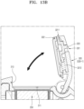
- FIGS. 13A and 13B are cross-sectional views illustrating the wireless probe 20 of FIGS. 12A and 12B .
- the housing 210 includes the housing cap 320 having an open position 3201 for opening the opening 311 of the outer housing 310 and a closed position 320-2 for closing the opening 311.
- the housing cap 320 may be configured to selectively close the opening 311 of the outer housing 310.
- the housing cap 320 may be supported on the outer housing 310 to pivot between the open position 320-1 for opening the opening 311 and the closed position 320-2 for closing the opening 311.
- the housing cap 320 may include a locking member 321 configured to maintain the closed position 320-2.
- a locked state of the housing cap 320 may be maintained by the locking member 321.
- the locking member 321 may include a locking protrusion 3211 that may be inserted into a locking groove 313 of the housing 210, and a pressing member 3212 configured to press the locking protrusion 3211 so that the locking protrusion 3211 protrudes from a body of the housing cap 320.
- a sealing member 322 for preventing penetration of water between the outer housing 310 and the housing cap 320 may be located on at least one of the outer housing 310 and the housing cap 320.
- the housing cap 320 may further include the sealing member 322 located on a portion facing the opening 311 of the housing 210.
- the sealing member 322 may surround the opening 311 of the outer housing 310.
- the sealing member 322 may be compressed and deformed by the housing 210 and the body of the housing cap 320. Accordingly, water may be prevented from passing between the housing cap 320 and the housing 210 and penetrating into the battery 250 located inside the housing 210.
- the locking member 321 may include a manipulation member 323 to facilitate the release of a locked state by the housing cap 320.
- the manipulation member 323 may be a manipulation protrusion connected to the locking protrusion 3211 and exposed to the outside of the body of the housing cap 320.
- the user may easily move the locking protrusion 3211 in a direction opposite to a protruding direction by manipulating the manipulation member 323.
- the user may move the manipulation member 323 backward with a force greater than a force pressed by the pressing member 3212, to separate the locking protrusion 3211 of the locking member 321 from the locking groove 313 of the housing 210.
- FIGS. 14 to 24 are views illustrating other examples of a housing cap (e.g., 320a, 320b, 320c, and 320d) in the wireless probe 20, according to an embodiment.
- a housing cap e.g., 320a, 320b, 320c, and 320d
- FIG. 17 for convenience of explanation, a lower base 324 is not shown.
- the wireless probe 20 may include a housing cap 320a configured to close the opening 311 of the outer housing 310.
- the housing cap 320a may include a body 3201a that is rotatable with respect to the outer housing 310 and a cover member 3202a that is slidable with respect to the body 3201a.
- the cover member 3202a may include a guide portion 3203 provided on an inner surface to be slidable with respect to the body 3201a.
- a locking member 321a configured so that the housing cap 320a is maintained at the closed position 320-2 may be provided at an end of the cover member 3202a.
- the locking member 321a may be inserted into a locking groove 313a of an outer housing 310a.
- a button 3231a that is vertically movable and an elastic plate 3232a that provides a force for restoring the button 3231a to its original position when the button 3231a is pressed may be located on the cover member 3202a.
- the elastic plate 3232a may be fixed by a fixing member F1, and one end of the elastic plate 3232a may be bent in a cantilever shape.
- the body 3201a may include a through-hole 3203 through which the button 3231a and the elastic plate 3232a contact each other.
- the lower base 324 provided to be inserted into the opening 311 of the outer housing 310 may be fixed to a lower portion of the body 3201a.
- the body 3201a and the lower base 324 may be fixed by a fixing member F2.
- the sealing member 322 may be located on the lower base 324.
- the housing cap 320a may be configured to selectively slide only when the button 3231a is pressed.
- the elastic plate 3232a may include an interference protrusion 3233a protruding in a direction perpendicular to a sliding direction.
- a stopper 3207 for blocking sliding of the interference protrusion 3233a may be provided on the body 3201a.
- the interference protrusion 3233a may be separated from the stopper 3207 and thus, the cover member 3202a may be able to slide from the body 3201a.
- the wireless probe 20 may include a housing cap 320b configured to close the opening 311 of the outer housing 310.
- the housing cap 320b may include a body 3201b that is rotatable with respect to the outer housing 310 and a cover member 3202b that is rotatable with respect to the body 3201b.
- the body 3201b may include a locking member 321b configured so that the housing cap 320b is maintained at the closed position 320-2.
- the locking member 321b may have a groove structure into which a first locking protrusion 313b of the housing 210 may be inserted.
- the cover member 3202b may include a second locking member 321-1 configured so that the housing cap 320b is maintained at the closed position 320-2.
- the second locking member 321-1 may have a groove structure into which a second locking protrusion 313-1 of the outer housing 310 may be inserted.
- the cover member 3202b may be inserted into a cover groove 3208 provided in the body 3201b.
- a length of the cover member 3202b may be less than a length of the cover groove 3208. Accordingly, a user may easily pivot the cover member 3202b by putting his/her finger into a space between an end of the cover member 3202b and the cover groove 3208.
- the user may pivot the cover member 3202b to primarily pivot the housing cap 320b so that the second locking groove 321-1 of the cover member 3202b is separated from the second locking protrusion 313-1 of the housing 210.
- the user may hold the cover member 3202b and secondarily pivot the housing cap 320b to open the opening 311 of the housing 210.
- the cover member 3202b may function as a manipulation member.
- the housing caps 320, 320a, and 320b may pivot with respect to the outer housing 310.
- operations of the housing caps 320, 320a, and 320b are not limited thereto, and the housing caps 320, 320a, and 320b may be detachably assembled without pivoting with respect to the housing 210.
- a housing cap 320c may be detachably assembled to the outer housing 310.
- the housing cap 320c may include a locking member 321c that is pivotable in a direction intersecting a separation direction.
- the locking member 321c may rotate about a rotation shaft located along a direction parallel to the separation direction.
- the locking member 321c may be connected to a manipulation member 323c exposed to the outside of a body 3201c. Accordingly, when the manipulation member 323c is rotated, the locking member 321c located under the body 3201c may be rotated.
- a locking groove 313c into which an end of the locking member 321c may be inserted in the separation direction and through which an end of the inserted locking member 321c may move in a radial direction may be provided in the outer housing 310.
- a user may mount the housing cap 320c on the outer housing 310 so that an end of the locking member 321c is inserted into the locking groove 313c, and may rotate the manipulation member 323c to move the manipulation member 323c in the radial direction so that the end of the locking member 321c is caught by the locking groove 313c. Accordingly, the housing cap 320c may be mounted on the outer housing 310. The user may separate the housing cap 320c from the housing 210 in reverse order to the order in which the housing cap 320c is mounted.
- a structure in which the housing cap 320c is detachably mounted on the outer housing 310 is not limited thereto, and may vary.
- a housing cap 320d may be detachably assembled to the housing 210.
- the housing cap 320d may include a locking member 321d configured so that the outer housing 310 and the housing cap 320d are fixed by hook coupling.
- the locking member 321d may include a plurality of locking protrusions.
- a plurality of locking grooves 313d into which the plurality of locking protrusions may be respectively inserted may be provided in the outer housing 310.
- the housing cap 320d may further include a battery pressing portion 325 configured to press the battery 250.
- the battery pressing portion 325 may press the other end of the battery 250. Accordingly, the stability of electrical connection of the battery 250 may be ensured.
- FIG. 25A is a cross-sectional view illustrating the housing cap 320 of the wireless probe 20, according to an embodiment.
- FIG. 25B is a cross-sectional view illustrating the housing cap 320 of FIG. 25A in an open state.
- the wireless probe 20 may further include a sensor 314 for detecting whether the housing cap 320 is open.
- the sensor 314 may be located adjacent to a pivoting shaft of the housing cap 320.
- the sensor 314 may be configured to detect a member 326 provided on the housing cap 320.
- the sensor 314 may be a sensor for detecting an intensity of a magnetic field.
- the senor 314 may be a contact sensor whose contact state varies according to whether the housing cap 320 is open.
- Whether the first transducer 211 of the wireless probe 20 operates may vary according to information detected by the sensor 314. For example, when the open position 320-1 of the housing cap 320 is detected by the sensor 314, an operation of the first transducer 211 may be stopped. When the closed position 320-2 of the housing cap 320 is detected by the sensor 314, the first transducer 211 may operate. Accordingly, the first transducer 211 may be prevented from operating in a state where the housing cap 320 is open.
- the outer housing 310 of the wireless probe 20 may include an opening 311a through which the battery 250 may be inserted and separated into the battery accommodating unit 330 along the third direction Z.
- a battery 250A may include the battery body 260, without the electrode adjusting assembly 270, as shown in FIG. 27 .
- an electrode terminal for electrical connection with the battery body 260 may be located on a housing cap 320e.
- FIG. 28 is a diagram for describing a method of mounting the battery 250 in the wireless probe 20, according to an embodiment.
- a method of mounting the battery 250 of the wireless probe 20 may include operation S10 of inserting the battery 250 between the first transducer 221 and the circuit board 230 through the opening 311 of the outer housing 310 along a direction parallel to a longitudinal direction of the battery 250 and operation S20 of closing the opening 311 of the outer housing 310 by using the housing cap 320.
- the inserting of the battery 250 may include inserting the first electrode portion 251 and the second electrode portion 2723 of the battery 250 into the opening 311 and electrically connecting the first electrode portion 251 and the second electrode portion 2723 of the battery 250 to the first electrode terminal 341 and the second electrode terminal 342.
- an operation of the first transducer 211 may be controlled through the sensor 314. For example, even when the first electrode portion 251 and the second electrode portion 2723 are connected to the first electrode terminal 341 and the second electrode terminal 342, an operation of the first transducer 211 may be stopped before the opening 311 of the housing cap 320 is closed.
- the closing of the opening 311 of the outer housing 310 may include pivoting the housing cap 320 to switch the housing cap 320 from the open position 320-1 to the closed position 320-2. After the housing cap 320 is switched to the closed position 320-2, the housing cap 320 may be maintained at the closed position 320-2 by the locking member 321.
- the closing of the opening 311 of the outer housing 310 may include pivoting the housing cap 320 to which the housing cap 320 from the open position 320-1 to the closed position 320-2. After the housing cap 320 is switched to the closed position 320-2, the housing cap 320 may be maintained at the closed position 320-2 by the locking member 321.
- the housing cap 320 may be assembled to the outer housing 310 by using the locking member 321 to switch the housing cap 320 from the open position 320-1 to the closed position 320-2. After the housing cap 320 is switched to the closed position 320-2, the housing cap 320 may be maintained at the closed position 320-2 by the locking member 321.
- a wireless probe from and into which a battery may be separated and assembled to be located between a transducer and a circuit board may be provided.
- a wireless probe in which a battery is easily separated and assembled by inserting the battery into a housing along a longitudinal direction of the battery and waterproof performance is improved may be provided.
Landscapes
- Health & Medical Sciences (AREA)
- Life Sciences & Earth Sciences (AREA)
- Engineering & Computer Science (AREA)
- Physics & Mathematics (AREA)
- Medical Informatics (AREA)
- Biomedical Technology (AREA)
- Veterinary Medicine (AREA)
- Public Health (AREA)
- General Health & Medical Sciences (AREA)
- Biophysics (AREA)
- Nuclear Medicine, Radiotherapy & Molecular Imaging (AREA)
- Pathology (AREA)
- Radiology & Medical Imaging (AREA)
- Animal Behavior & Ethology (AREA)
- Heart & Thoracic Surgery (AREA)
- Surgery (AREA)
- Molecular Biology (AREA)
- Computer Networks & Wireless Communication (AREA)
- Remote Sensing (AREA)
- General Physics & Mathematics (AREA)
- Gynecology & Obstetrics (AREA)
- Radar, Positioning & Navigation (AREA)
- Ultra Sonic Daignosis Equipment (AREA)
Abstract
Description
- This application is based on and claims priority under 35 U.S.C. §119 to
Korean Patent Application Nos. 10-2023-00037596 10-2023-0110768 - The disclosure provides a wireless probe including a battery that may be separated and assembled.
- An ultrasound diagnostic apparatus irradiates an ultrasound signal generated from a transducer of a probe to an object, receives information from a signal reflected from the object, and obtains at least one image of a region (e.g., soft tissue or blood flow) inside the object.
- In such an ultrasound diagnostic apparatus, a wireless probe connected to an external device, for example, a main body, through a wireless network is being developed so that a user may operate the probe without spatial constraints. The wireless probe does not include a separate wiring for receiving power from the outside, and may receive power by using an internal battery.
- However, because such a wireless probe receives power by using a battery, the battery needs to be charged or replaced with a new battery before becoming completely discharged.
- A wireless probe according to an embodiment may provide a structure in which a battery may be separated and assembled to be located between a transducer and a circuit board.
- A wireless probe according to an embodiment may allow a battery to be inserted into a housing along a longitudinal direction of the battery, thereby facilitating separation and assembly of the battery and improving waterproof performance.
- Additional aspects will be set forth in part in the description which follows and, in part, will be apparent from the description, or may be learned by practice of the presented embodiments.
- According to an aspect of the disclosure, a wireless probe includes
- a housing having a length in a first direction,
- a first transducer located at one end of the housing in the first direction,
- a circuit board located inside the housing and electrically connected to the first transducer, and
- a battery located between the first transducer and the circuit board inside the housing and having a length in a second direction perpendicular to the first direction,
- wherein the housing is configured to allow the battery to be inserted and separated along the second direction.
- The housing may include an outer housing forming an exterior and including an opening formed at one end in the second direction, a housing cap forming an exterior and configured to open and close the opening, and a battery accommodating unit located inside the outer housing and accommodating the battery inserted through the opening therein.
- The battery accommodating unit may be connected to the opening, has a cross-sectional shape corresponding to a cross-sectional shape of the battery, and extends along the second direction.
- The wireless probe may further include at least one flexible circuit unit electrically connecting the circuit board to the first transducer and formed to bypass the battery accommodating unit.
- The battery may include a first electrode portion and a second electrode portion located adjacent to each other at the front in an insertion direction.
- The battery may include a battery body including a first electrode and a second electrode having different polarities and provided at both ends in a longitudinal direction, and an electrode adjusting assembly exposing the first electrode to outside to form the first electrode portion, covering the second electrode, and electrically connected to the second electrode to form the second electrode portion adjacent to the first electrode portion.
- The electrode adjusting assembly may include an inner insulator configured to surround an outer surface of the battery body and expose the first electrode and the second electrode through both ends of the inner insulator, an electrode moving body including an electrode contact portion contacting the second electrode exposed through the inner insulator, the second electrode portion located at a position spaced apart from the electrode contact portion, and an extending portion electrically connecting the electrode contact portion to the second electrode portion, and an outer insulator configured to surround an outer surface of the inner insulator, cover the electrode contact portion and the extending portion of the electrode moving body, and expose the second electrode portion.
- The battery accommodating unit may include a first electrode terminal for electrical contact with the first electrode portion of the battery, and a second electrode terminal for electrical contact with the second electrode portion of the battery, wherein directions of the first electrode terminal and the second electrode terminal are perpendicular to each other.
- An outer diameter of the second electrode portion may be less than an outer diameter of the outer insulator so that the second electrode portion forms a concave portion of the battery.
- When the battery is inserted into the battery accommodating unit, a distance between the second electrode portion and the opening along the second direction may be greater than a distance between the second electrode and the opening along the second direction.
- A difference between a length of the first transducer along the second direction and a length of the battery along the second direction may be 20% or less of the length of the battery along the second direction.
- The housing cap may have an open position for opening the opening and a closed position for closing the opening, wherein the housing cap includes a locking member configured to maintain the closed position.
- The wireless probe may further include a manipulation member configured to facilitate release of a locked state by the locking member.
- The wireless probe may further include a sealing member located on at least one of the outer housing and the housing cap to prevent penetration of water between the outer housing and the housing cap.
- The wireless probe may further include a sensor configured to detect whether the housing cap is at an open position, wherein an operation of the first transducer is controlled based on a detection result of the sensor.
- The wireless probe may further include a second transducer located at the other end of the housing,
- wherein a width of the first transducer in the second direction is different from a width of the second transducer in the second direction.
- The above and other aspects, features, and advantages of certain embodiments will be more apparent from the following description taken in conjunction with the accompanying drawings, in which:
-
FIG. 1 is a block diagram illustrating a configuration of an ultrasound diagnostic apparatus, according to an embodiment; -
FIG. 2 is a perspective view illustrating a wireless probe, according to an embodiment; -
FIG. 3 is an exploded perspective view illustrating a wireless probe, according to an embodiment; -
FIG. 4 is a perspective view illustrating a state where a battery is separated from a wireless probe, according to an embodiment; -
FIG. 5 is a perspective view illustrating an internal configuration of a housing in the wireless probe ofFIG. 4 ; -
FIG. 6 is a perspective view illustrating a battery accommodating unit in a wireless probe, according to an embodiment; -
FIG. 7 is a cross-sectional perspective view illustrating the wireless probe ofFIG. 6 ; -
FIG. 8 is a perspective view illustrating a wireless probe, according to an embodiment; -
FIG. 9 is a perspective view illustrating a battery used in a wireless probe, according to an embodiment; -
FIG. 10 is an exploded perspective view illustrating the battery ofFIG. 9 ; -
FIG. 11 is a cross-sectional view illustrating a part of the wireless probe ofFIG. 6 taken along a plane perpendicular to a third direction; -
FIGS. 12A and12B are perspective views illustrating a housing cap in a wireless probe, according to an embodiment; -
FIGS. 13A and13B are cross-sectional views illustrating the wireless probe ofFIGS. 12A and12B ; -
FIG. 14 is a view illustrating another example of a housing cap in a wireless probe, according to an embodiment; -
FIG. 15 is a view for describing an operation of the housing cap ofFIG. 14 ; -
FIG. 16 is an exploded perspective view illustrating the housing cap ofFIG. 14 ; -
FIG. 17 is a view for describing a lower structure of the housing cap ofFIG. 14 ; -
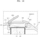
FIG. 18 is a cross-sectional view illustrating another example of a housing cap in a wireless probe, according to an embodiment; -
FIG. 19 is a cross-sectional view illustrating a state where a locked state is released by a locking member of the housing cap ofFIG. 18 ; -
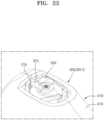
FIG. 20 is a view illustrating another example of a housing cap in a wireless probe, according to an embodiment; -
FIG. 21 is a view for describing a state where the housing cap ofFIG. 20 is separated from a housing; -
FIG. 22 is a view for describing an operation of the housing cap ofFIG. 20 ; -
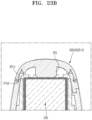
FIG. 23A is a perspective view illustrating another example of a housing cap in a wireless probe, according to an embodiment; -
FIG. 23B is a cross-sectional view illustrating the wireless probe ofFIG. 23A ; -
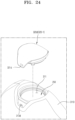
FIG. 24 is a perspective view illustrating a state where a housing cap is separated from a housing inFIG. 23A ; -
FIG. 25A is a cross-sectional view illustrating a housing cap of a wireless probe, according to an embodiment; -
FIG. 25B is a cross-sectional view illustrating the housing cap ofFIG. 25A in an open state; -
FIG. 26 is a perspective view illustrating another example of a wireless probe, according to an embodiment; -
FIG. 27 is a perspective view illustrating another example of a wireless probe, according to an embodiment; and -
FIG. 28 is a diagram for describing a method of mounting a battery in a wireless probe, according to an embodiment. - Reference will now be made in detail to embodiments, examples of which are illustrated in the accompanying drawings, wherein like reference numerals refer to like elements throughout. In this regard, the present embodiments may have different forms and should not be construed as being limited to the descriptions set forth herein. Accordingly, the embodiments are merely described below, by referring to the figures, to explain aspects of the present description. As used herein, the term "and/or" includes any and all combinations of one or more of the associated listed items. Expressions such as "at least one of," when preceding a list of elements, modify the entire list of elements and do not modify the individual elements of the list.
- Hereinafter, principles and embodiments will be described in detail in order to fully convey the scope of the claims of the disclosure and enable one of ordinary skill in the art to embody and practice the disclosure. The embodiments may be implemented in various forms.
- Throughout the disclosure, like reference numerals denote like elements. All elements of the embodiments are not described in the disclosure, and descriptions of matters well known in the art to which the disclosure pertains or repeated descriptions between embodiments will not be given. The terms such as "module", "part", and "portion" used herein denote those that may be embodied by software or hardware. According to embodiments, a plurality of modules, parts, or portions may be embodied by a single unit or element, or a single part or portion may include a plurality of elements. Embodiments and principles of the embodiments will now be described with reference to the accompanying drawings.
- In the disclosure, an image may include a medical image obtained by a medical imaging apparatus such as magnetic resonance imaging (MRI) apparatus, a computed tomography (CT) apparatus, an ultrasound imaging apparatus, or an X-ray imaging apparatus.
- In the disclosure, an "object" may be a target to be imaged and may include a human, an animal, or a part of a human or animal. For example, an object may include a body part (e.g., an organ) or a phantom.
- Throughout the disclosure, an "ultrasound image" refers to an image of an object processed based on an ultrasound signal transmitted to the object and reflected therefrom.
- Hereinafter, embodiments will be described in detail with reference to the drawings.
-
FIG. 1 is a block diagram illustrating a configuration of an ultrasounddiagnostic apparatus 100, according to an embodiment. - Referring to
FIG. 1 , the ultrasounddiagnostic apparatus 100 may include awireless probe 20 and anultrasound imaging apparatus 40. - The
wireless probe 20 may include atransmission module 113, atransducer 115, areception module 117, aprocessor 118, and acommunication module 119. Although thewireless probe 20 includes both thetransmission module 113 and thereception module 117 inFIG. 1 , according to an implementation type, thewireless probe 20 may include only some of components of thetransmission module 113 and thereception module 117 and some of components of thetransmission module 113 and thereception module 117 may be included in theultrasound imaging apparatus 40. Alternatively, the wireless prove 20 may further include animage processor 130. - The
transducer 115 may include a plurality of transducer members. The plurality of transducer members may transmit an ultrasound signal to anobject 10 according to a transmission signal applied from thetransmission module 113. The plurality of transducer members may receive an ultrasound signal reflected from theobject 10 to form a reception signal. - The
processor 118 controls thetransmission module 113 to form a transmission signal to be applied to each of the plurality of transducer members, by considering positions and focal points of the plurality of transducer members. - The
processor 118 controls thereception module 117 to convert a reception signal received from thetransducer 115 through analog-to-digital conversion and add digitally converted reception signals by considering positions and focal points of the plurality of transducer members to generate ultrasound data. Alternatively, when thewireless probe 20 includes theimage processor 130, an ultrasound image may be generated by using the generated ultrasound data. - The
communication module 119 may wirelessly transmit the generated ultrasound data or ultrasound image to theultrasound imaging apparatus 40 through a wireless network. Also, thecommunication module 119 may receive a control signal and data from theultrasound imaging apparatus 40. - Also, the ultrasound
diagnostic apparatus 100 may be connected to one or more wireless probes 20 according to an implementation type. - The
ultrasound imaging apparatus 40 may receive the ultrasound data or ultrasound image from thewireless probe 20. Theultrasound imaging apparatus 40 may include aprocessor 120, theimage processor 130, adisplay 140, amemory 150, acommunication module 160, and aninput interface 170. - The
image processor 130 generates an ultrasound image, by using the ultrasound data received from thewireless probe 20. - The
display 140 may display the ultrasound image received from thewireless probe 20, the ultrasound image generated by theultrasound imaging apparatus 40, and various information processed by the ultrasounddiagnostic apparatus 100. The ultrasounddiagnostic apparatus 100 may include one ormore displays 140 according to an implementation type. Also, thedisplay 140 may include a touch panel or a touchscreen. - The
processor 120 may control an overall operation of the ultrasounddiagnostic apparatus 100 and a signal flow between internal elements of the ultrasounddiagnostic apparatus 100. Theprocessor 120 may perform or control various operations or functions of the ultrasounddiagnostic apparatus 100 by executing a program stored in thememory 150. Also, theprocessor 120 may control an operation of the ultrasounddiagnostic apparatus 100 by receiving a control signal from theinput interface 170 or an external device. - The
ultrasound imaging apparatus 40 includes thecommunication module 160, and may be connected to an external device (e.g., a server, a medical device, a portable device (e.g., a smartphone, a tablet PC, or a wearable device)) through thecommunication module 160. - The
communication module 160 may include one or more elements that enable communication with an external device. For example, thecommunication module 160 may include at least one of a short-range communication module, a wired communication module, and a wireless communication module. - The
communication module 160 may receive a control signal and data from an external device and transmit the received control signal to theprocessor 120 so that theprocessor 120 controls the ultrasounddiagnostic apparatus 100 according to the received control signal. - Alternatively, the
processor 120 may transmit a control signal to an external device through thecommunication module 160, to control the external device according to the control signal of the processor. - For example, the external device may process data of the external device according to the control signal of the processor received through the communication module.
- Because a program for controlling the ultrasound
diagnostic apparatus 100 may be installed in the external device, the program may include instructions for performing some or all of operations of theprocessor 120. - The program may be pre-installed in the external device, or a user of the external device may download and install the program from a server that provides an application. A recording medium in which the program is stored may be included in the server that provides the application.
- The
memory 150 may store various data or programs for driving and controlling the ultrasounddiagnostic apparatus 100, input/output ultrasound data, and an ultrasound image. - The
input interface 170 receives the user's input for controlling the ultrasounddiagnostic apparatus 100. For example, the user's input may include, but is not limited to, an input manipulating a button, a keypad, a mouse, a trackball, a jog switch, or a knop, an input that touches the touch pad or the touchscreen, a voice input, a motion input, or a biometric information input (e.g., iris recognition or fingerprint recognition). -
FIG. 2 is a perspective view illustrating thewireless probe 20, according to an embodiment.FIG. 3 is an exploded perspective view illustrating thewireless probe 20, according to an embodiment. - Referring to
FIGS. 2 and3 , thewireless probe 20 according to an embodiment may include ahousing 210, afirst transducer 221, acircuit board 230, and abattery 250. - The
housing 210 may have a length in a first direction X. Thehousing 210 may have a width in a second direction Y perpendicular to the first direction X, and may have a thickness in a third direction Z perpendicular to both the first direction X and the second direction Y. In thehousing 210, a length in the first direction X may be greater than a width in the second direction Y, and the width in the second direction Y may be greater than a thickness in the third direction Z. - A width of the
housing 210 in the second direction Y may vary according to a position in the first direction X. For example, a width of one end of thehousing 210 in the first direction X may be greater than a width of the other end of thehousing 210 in the first direction X. - The
first transducer 221 may be located at one end of thehousing 210 in the first direction X. Thefirst transducer 221 for transmitting and receiving an ultrasound wave toward a subject may include a plurality of transducer members. - The plurality of transducer members of the
first transducer 221 may be arranged in the second direction Y. For example, the plurality of transducer members of thefirst transducer 221 may be convexly arranged along the second direction Y. - A
second transducer 222 may be located at the other end of thehousing 210 in the first direction X. Thefirst transducer 221 may be located at one end of thehousing 210 in the first direction X, and thesecond transducer 222 may be located at the other end of thehousing 210 in the first direction X. - A plurality of transducer members of the
second transducer 222 may be arranged in the second direction Y. For example, the plurality of transducer members of thesecond transducer 222 may be linearly arranged along the second direction Y. - A width W1 of the
first transducer 221 in the second direction Y may be different from a width W2 of thesecond transducer 222 in the second direction Y. For example, the width W1 of thefirst transducer 221 in the second direction Y may be greater than the width W2 of thesecond transducer 222 in the second direction Y. In other words, the width W2 of thesecond transducer 222 in the second direction Y may be less than the width W1 of thefirst transducer 221 in the second direction Y. - The
circuit board 230 may be located inside thehousing 210. Thecircuit board 230 may be located inside ahandle portion 2101 that is a portion of thehousing 210 having a small width in the second direction Y. A width of thecircuit board 230 in the second direction Y may be less than a width of thehandle portion 2101 of thehousing 210 in the second direction Y, and may be 80% or more of the width of thehandle portion 2101 of thehousing 210 in the second direction Y. - The
circuit board 230 may be supported by a board support (not shown) located inside thehousing 210. The board support may be an element separate from thehousing 210, but the disclosure is not limited thereto, and the board support may be integrally formed with thehousing 210. - The
circuit board 230 may include a transmission/reception circuit for transmitting/receiving data to/from thefirst transducer 221 and thesecond transducer 222. Thecircuit board 230 may include a plurality of sub-circuit boards stacked along the third direction Z. For example, thecircuit board 230 may include a firstsub-circuit board 2301, a secondsub-circuit board 2302, and a thirdsub-circuit board 2303. The firstsub-circuit board 2301 may include a transmission/reception circuit, the secondsub-circuit board 2302 may include a power circuit, and the thirdsub-circuit board 2303 may include a control circuit. However, a type of a circuit located on each sub-circuit board is not limited thereto, and may be appropriately changed as necessary. - The
circuit board 230 may be located inside thehousing 210, and may be electrically connected to at least one transducer. For example, thecircuit board 230 may be electrically connected to thefirst transducer 221, and may be electrically connected to thesecond transducer 222. For example, the firstsub-circuit board 2301 may be electrically connected to thefirst transducer 221, and may be electrically connected to thesecond transducer 222. - The
circuit board 230 and at least one transducer may be electrically connected by at least one flexible circuit unit. - For example, the
first transducer 221 may be electrically connected to thecircuit board 230 by at least one firstflexible circuit unit 241. For example, the plurality of transducer members of thefirst transducer 221 may be electrically connected to thecircuit board 230 by at least one firstflexible circuit unit 241. For example, the plurality of transducer members of thefirst transducer 221 may be electrically connected to thecircuit board 230 by a plurality of firstflexible circuit units flexible circuit units 241 is not limited thereto, and may be changed in consideration of the number of transducer members, etc. - For example, the
second transducer 222 may be electrically connected to thecircuit board 230 by at least one secondflexible circuit unit 242. For example, the plurality of transducer members of thesecond transducer 222 may be electrically connected to thecircuit board 230 by at least one secondflexible circuit unit 242. For example, the plurality of transducer members of thesecond transducer 222 may be electrically connected to thecircuit board 230 by a plurality of secondflexible circuit units flexible circuit units 242 is not limited thereto, and may be changed in consideration of the number of transducer members, etc. - The
battery 250 may be located inside thehousing 210, and may provide power for operating thewireless probe 20. Thebattery 250 may provide power to the first andsecond transducers wireless probe 20. Thebattery 250 may be a rechargeable secondary battery. In another example, thebattery 250 may be a non-rechargeable battery. - The
battery 250 may have a shape that is long in a longitudinal direction. For example, a length of thebattery 250 may be greater than a diameter (or a width) of thebattery 250. For example, a length of thebattery 250 may be greater than twice a diameter of thebattery 250. A length of thebattery 250 may be greater than three times a diameter of thebattery 250. - The
battery 250 may include a standardized battery body 260 (seeFIG. 10 ). For example, thebattery body 260 may have a cylindrical shape. For example, thebattery body 260 may be a cylindrical battery having a diameter of 18 mm and a length of 65 mm. Because thestandardized battery 250 is used as thebattery body 260, a user may easily obtain thebattery body 260 for supplying power to thewireless probe 20. - A length L1 of the
battery 250 in the second direction Y may correspond to the width W1 of thefirst transducer 221 in the second direction Y. For example, a difference between the width W1 of thefirst transducer 221 along the second direction Y and the length L1 of thebattery 250 along the second direction Y may be 20% or less of the length L1 of thebattery 250 along the second direction Y. The length L1 of the battery in the second direction Y may be greater than the width W2 of thesecond transducer 222 in the second direction Y. The length L1 of thebattery 250 according to the second direction Y may be greater than 1.2 times the width W2 of thesecond transducer 222 in the second direction Y. - The
wireless probe 20 may perform an ultrasound scan operation by receiving power from thebattery 250 located therein, without receiving power from the outside. However, because thewireless probe 20 receives power from thebattery 250, thebattery 250 needs to be charged or replaced with a chargedbattery 250 before being completely discharged. - The
wireless probe 20 according to an embodiment may provide a structure in which the user may easily replace thebattery 250 and waterproof performance may be maintained. -
FIG. 4 is a perspective view illustrating a state where thebattery 250 is separated from thewireless probe 20, according to an embodiment.FIG. 5 is a perspective view illustrating an internal configuration of thehousing 210 in thewireless probe 20 of FIGF. 4. - Referring to
FIGS. 4 and5 , thehousing 210 of thewireless probe 20 according to an embodiment may be configured to allow thebattery 250 to be inserted and separated along the second direction Y. In other words, thebattery 250 may be configured to be inserted into and separated from thehousing 210 along the second direction Y parallel to a longitudinal direction of thebattery 250. - The
housing 210 according to an embodiment may include anouter housing 310, ahousing cap 320, and abattery accommodating unit 330. - The
outer housing 310 forms the exterior of thewireless probe 20, and includes anopening 311 provided at one end in the second direction Y. Theopening 311 may have a shape corresponding to a cross-sectional shape of thebattery 250. For example, a diameter of theopening 311 may correspond to a diameter of thebattery 250. - The
outer housing 310 may include a plurality ofhousing members outer housing 310 may include a plurality ofhousing members - The
housing cap 320 may form the exterior of thewireless probe 20 along with theouter housing 310, and may be configured to open and close theopening 311. A configuration of thehousing cap 320 will be described below with reference toFIG. 12A . - The
battery accommodating unit 330 may be located inside theouter housing 310. For example, thebattery accommodating unit 330 may be located inside theouter housing 310 to be connected to theopening 311 of theouter housing 310. Thebattery accommodating unit 330 may include aposition setting portion 3311 inserted into aposition setting portion 3121 of theouter housing 310. Due to theposition setting portion 3121 of theouter housing 310 and theposition setting portion 3311 of thebattery accommodating unit 330, thebattery accommodating unit 330 may be maintained at a constant position inside theouter housing 310. - The
battery accommodating unit 330 includes one end into which thebattery 250 may be inserted. The one end of thebattery accommodating unit 330 may face theopening 311 of theouter housing 310. - The
battery accommodating unit 330 may have an inner space in which at least a part of thebattery 250 inserted through theopening 311 is accommodated. - The
battery accommodating unit 330 may be configured so that thebattery 250 is inserted and separated along the second direction Y. For example, thebattery accommodating unit 330 may extend along the second direction Y. For example, thebattery accommodating unit 330 may have a cross-sectional shape corresponding to a cross-sectional shape of thebattery 250. For example, when thebattery 250 has a circular cross-sectional shape, thebattery accommodating unit 330 may have a circular cross-sectional shape. - When the
battery 250 is inserted into theouter housing 310 or separated from theouter housing 310, thebattery accommodating unit 330 may guide thebattery 250 to move along a certain direction. For example, thebattery accommodating unit 330 may guide thebattery 250 to move in the second direction Y. To this end, in an example, thebattery accommodating unit 330 may extend along the second direction Y. - The
battery accommodating unit 330 may be configured to define a position of thebattery 250 in theouter housing 310. For example, thebattery accommodating unit 330 may be located between thefirst transducer 221 and thecircuit board 230. - Although the
battery accommodating unit 330 is an element separate from theouter housing 310 inFIGS. 4 and5 , the disclosure is not limited thereto. For example, thebattery accommodating unit 330 and theouter housing 310 may be one element. Also, although thebattery 250 may be inserted into and separated from the right side of thewireless probe 20 inFIGS. 4 and5 , the disclosure is not limited thereto, and various modifications may be made. For example, thebattery 250 may be inserted into and separated from the left side of thewireless probe 20. -
FIG. 6 is a perspective view illustrating thebattery accommodating unit 330 in thewireless probe 20, according to an embodiment.FIG. 7 is a cross-sectional perspective view illustrating thewireless probe 20 ofFIG. 6 .FIG. 8 is a perspective view illustrating thewireless probe 20, according to an embodiment. InFIGS. 6 to 8 , for convenience of illustration, a part of thehousing member 3101 of theouter housing 310 is not shown. - Referring to
FIGS. 6 and7 , in thewireless probe 20 according to an embodiment, thebattery 250 may be inserted into thebattery accommodating unit 330. For example, a side surface of thebattery 250 may be surrounded by thebattery accommodating unit 330. The firstflexible circuit unit 241 may be located to bypass thebattery accommodating unit 330. While thebattery 250 is inserted into or separated from thebattery accommodating unit 330, thebattery accommodating unit 330 may prevent contact between the firstflexible circuit unit 241 and thebattery 250. Accordingly, damage to the firstflexible circuit unit 241 may be prevented. - The first
flexible circuit unit 241 may be located to pass through aside portion 331 of thebattery accommodating unit 330. For example, the firstflexible circuit unit 241 may surround a part of theside portion 331 of thebattery accommodating unit 330. One end of the firstflexible circuit unit 241 may be connected to thefirst transducer 221, and the other end of the firstflexible circuit unit 241 may be connected to thecircuit board 230. - A plurality of first
flexible circuit units 241 may be provided. For example, one firstflexible circuit unit 241b from among the plurality of firstflexible circuit units side portion 331 of thebattery accommodating unit 330. The other firstflexible circuit unit 241a from among the plurality of firstflexible circuit units flexible circuit unit 241b. The other firstflexible circuit unit 241a from among the plurality of firstflexible circuit units flexible circuit unit 241b. - The plurality of first
flexible circuit units circuit board 230. For example, the firstflexible circuit unit 241b may be connected to one surface, for example, a bottom surface, of the firstsub-circuit board 2301, and the other firstflexible circuit unit 241a may be connected to the other surface, for example, a top surface, of the firstsub-circuit board 2301. - However, a position of the first
flexible circuit unit 241 in thewireless probe 20 is not limited thereto, and may vary. For example, as shown inFIG. 8 , each of the plurality of firstflexible circuit units side portion 331 of thebattery accommodating unit 330. The firstflexible circuit unit 241b and the other firstflexible circuit unit 241a from among the plurality of firstflexible circuit units circuit board 230. -
FIG. 9 is a perspective view illustrating thebattery 250 used in thewireless probe 20, according to an embodiment.FIG. 10 is an exploded perspective view illustrating thebattery 250 ofFIG. 9 .FIG. 11 is a cross-sectional view illustrating a part of thewireless probe 20 ofFIG. 6 taken along a plane perpendicular to the third direction Z. - Referring to
FIGS. 9 to 11 , thebattery 250 according to an embodiment may be located so that afirst electrode portion 251 and asecond electrode portion 2723 are adjacent to each other. Thefirst electrode portion 251 and thesecond electrode portion 2723 may have different polarities. In thebattery 250, thefirst electrode portion 251 and thesecond electrode portion 2723 may be located adjacent to each other at the front in an insertion direction of thebattery 250. - A distance D between the
first electrode portion 251 and thesecond electrode portion 2723 may be less than 1/2 of the length L1 of thebattery 250. The distance D between thefirst electrode portion 251 and thesecond electrode portion 2723 may be less than 1/5 of the length L1 of thebattery 250. The distance D between thefirst electrode portion 251 and thesecond electrode portion 2723 may be less than 1/10 of the length L1 of thebattery 250. The distance D between thefirst electrode portion 251 and thesecond electrode portion 2723 may be 10 mm or less. The distance D between thefirst electrode portion 251 and thesecond electrode portion 2723 may be 5 mm or less. The length L1 of thebattery 250 may be the length L1 of thebattery 250 along the second direction Y. - The
battery 250 may include thebattery body 260 and anelectrode adjusting assembly 270 for complementing an electrode position of thebattery body 260. - In the
battery body 260, afirst electrode 261 and asecond electrode 262 having different polarities may be provided at both ends in the longitudinal direction. Thefirst electrode 261 may be located at one end of thebattery body 260, and thesecond electrode 262 may be located at the other end of thebattery body 260. In an example, thefirst electrode 261 may be a positive electrode, and thesecond electrode 262 may be a negative electrode. In another example, thefirst electrode 261 may be a negative electrode, and thesecond electrode 262 may be a positive electrode. - The
battery body 260 may be a standard battery. For example, thebattery body 260 may have a shape that is long in the longitudinal direction. For example, a length of thebattery body 260 may be greater than a diameter (or a width) of thebattery body 260. For example, a length of thebattery body 260 may be greater than twice a diameter of thebattery body 260. A length of thebattery body 260 may be greater than three times a diameter of thebattery body 260. Thebattery body 260 may have a cylindrical shape. For example, thebattery body 260 may be thecylindrical battery 250 having a diameter of 18 mm and a length of 65 mm. - The
electrode adjusting assembly 270 may expose thefirst electrode 261 of thebattery body 260 to the outside to form thefirst electrode portion 251. In other words, thefirst electrode 261 exposed to the outside of theelectrode adjusting assembly 270 may function as thefirst electrode portion 251 of thebattery 250. - The
electrode adjusting assembly 270 may cover thesecond electrode 262 of thebattery body 260. Theelectrode adjusting assembly 270 may be electrically connected to thesecond electrode 262 to form thesecond electrode portion 2723 adjacent to thefirst electrode portion 251. Because theelectrode adjusting assembly 270 may allow electrical contact through thesecond electrode portion 2723 adjacent to thefirst electrode portion 251 while covering thesecond electrode portion 2723 to prevent external exposure of thesecond electrode portion 2723, the waterproof performance of thewireless probe 20 may be improved. - To this end, in an example, the
electrode adjusting assembly 270 may include aninner insulator 271, anelectrode moving body 272, and anouter insulator 273. - The
inner insulator 271 may surround a side surface of thebattery body 260 and expose thefirst electrode 261 and thesecond electrode 262 of thebattery body 260 through both ends of theinner insulator 271. - The
inner insulator 271 may have an internal shape corresponding to a side shape of thebattery body 260. Theinner insulator 271 may include an insulatingring 2711 for insulation between thefirst electrode portion 251 and thesecond electrode portion 2723. The insulatingring 2711 of theinner insulator 271 may have a larger outer diameter than other portions of theinner insulator 271. - The
inner insulator 271 may include first andsecond openings first electrode 261 and thesecond electrode 262 of thebattery body 260 are exposed. Thefirst electrode 261 of thebattery body 260 may be exposed through thefirst opening 2712 of theinner insulator 271, and thesecond electrode 262 of thebattery body 260 may be exposed through thesecond opening 2713 of theinner insulator 271. - The
electrode moving body 272 may include anelectrode contact portion 2721 contacting thesecond electrode 262 exposed through theinner insulator 271, thesecond electrode portion 2723 located at a position spaced apart from theelectrode contact portion 2721, and an extendingportion 2722 electrically connecting theelectrode contact portion 2721 to thesecond electrode portion 2723. Theelectrode moving body 272 may include a conductive material for electrical connection with thesecond electrode 262. - The
second electrode portion 2723 may have a ring shape surrounding theinner insulator 271. The extendingportion 2722 may extend in the longitudinal direction of thebattery 250. However, a shape of thesecond electrode portion 2723 and an extending direction of the extendingportion 2722 are not limited thereto, and may vary. - The
outer insulator 273 may surround a side surface of theinner insulator 271. The extendingportion 2722 of theelectrode moving body 272 may be located between theouter insulator 273 and theinner insulator 271. Theouter insulator 273 may cover theelectrode contact portion 2721 of theelectrode moving body 272. Theouter insulator 273 may expose thesecond electrode portion 2723 of theelectrode moving body 272. - The
outer insulator 273 may exposed one end of thebattery body 260 where thefirst electrode 261 is formed to the outside, and may cover a side surface of thebattery body 260 and the other end of thebattery body 260 where thesecond electrode 262 is formed. - The
battery 250 may be configured so that thesecond electrode portion 2723 forms a concave portion. For example, an outer diameter of thesecond electrode portion 2723 may be less than an outer diameter of theouter insulator 273. For example, an outer diameter of thesecond electrode portion 2723 may be less than an outer diameter of the insulatingring 2711 of theinner insulator 271. In otherwords, thesecond electrode portion 2723 having a smaller outer diameter than theouter insulator 273 and theinner insulator 271 may form a concave portion of thebattery 250. - Referring to
FIGS. 6 and11 , in thewireless probe 20 according to an embodiment, thebattery 250 may be configured so that an end where thefirst electrode portion 251 is formed is first inserted into theopening 311 of theouter housing 310. For example, in thebattery accommodating unit 330, afirst electrode terminal 341 and asecond electrode terminal 342 for electrical connection with thebattery 250 may be installed. - The
first electrode terminal 341 may electrically contact thefirst electrode portion 251 of thebattery 250. Thesecond electrode terminal 342 may electrically contact thesecond electrode portion 2723 of thebattery 250. - Directions of the
first electrode terminal 341 and thesecond electrode terminal 342 may be perpendicular to each other. For example, thefirst electrode terminal 341 may be located along a direction parallel to the insertion direction of thebattery 250. Thesecond electrode terminal 342 may be located along a direction perpendicular to the insertion direction of thebattery 250. - The
second electrode terminal 342 may be inserted into the concave portion of thebattery 250 where thesecond electrode portion 2723 is located. Because thesecond electrode terminal 342 is inserted into the concave portion of thebattery 250, an insertion position of thebattery 250 electrically connected to thewireless probe 20 may be maintained, and while a user mounts thebattery 250, the user may easily recognize whether thebattery 250 has reached the insertion position. - As described above, in the
wireless probe 20, the first andsecond electrode portions opening 311 of theouter housing 310. For example, a distance between the first andsecond electrode portions battery 250 and theopening 311 of theouter housing 310 may increase. For example, when thebattery 250 is inserted into thebattery accommodating unit 330, a distance between thesecond electrode portion 2723 of the battery and theopening 311 of theouter housing 310 along the second direction Y may be greater than a distance between thesecond electrode 262 of thebattery body 260 and theopening 311 of theouter housing 310 along the second direction Y. - Accordingly, the waterproof performance of the
wireless probe 20 may be improved. For example, even when water penetrates into theopening 311 of theouter housing 310, a distance through which the penetrated water reaches the first andsecond electrode portions battery 250 is increased, thereby improving waterproof performance. - However, a structure of the
battery 250 is not limited thereto, and may include thebattery body 260 without theelectrode adjusting assembly 270. In this case, a position of thesecond electrode terminal 342 may be changed. -
FIGS. 12A and12B are perspective views illustrating thehousing cap 320 in thewireless probe 20, according to an embodiment.FIGS. 13A and13B are cross-sectional views illustrating thewireless probe 20 ofFIGS. 12A and12B . - Referring to
FIGS. 12A and12B , thehousing 210 according to an embodiment includes thehousing cap 320 having an open position 3201 for opening theopening 311 of theouter housing 310 and a closed position 320-2 for closing theopening 311. Thehousing cap 320 may be configured to selectively close theopening 311 of theouter housing 310. Thehousing cap 320 may be supported on theouter housing 310 to pivot between the open position 320-1 for opening theopening 311 and the closed position 320-2 for closing theopening 311. - Referring to
FIGS. 13A and13B , thehousing cap 320 may include a lockingmember 321 configured to maintain the closed position 320-2. A locked state of thehousing cap 320 may be maintained by the lockingmember 321. The lockingmember 321 may include alocking protrusion 3211 that may be inserted into a lockinggroove 313 of thehousing 210, and apressing member 3212 configured to press the lockingprotrusion 3211 so that the lockingprotrusion 3211 protrudes from a body of thehousing cap 320. - A sealing
member 322 for preventing penetration of water between theouter housing 310 and thehousing cap 320 may be located on at least one of theouter housing 310 and thehousing cap 320. For example, thehousing cap 320 may further include the sealingmember 322 located on a portion facing theopening 311 of thehousing 210. The sealingmember 322 may surround theopening 311 of theouter housing 310. - As shown in
FIG. 13A , when the lockingmember 321 is inserted into the lockinggroove 313, the sealingmember 322 may be compressed and deformed by thehousing 210 and the body of thehousing cap 320. Accordingly, water may be prevented from passing between thehousing cap 320 and thehousing 210 and penetrating into thebattery 250 located inside thehousing 210. - The locking
member 321 may include amanipulation member 323 to facilitate the release of a locked state by thehousing cap 320. For example, themanipulation member 323 may be a manipulation protrusion connected to thelocking protrusion 3211 and exposed to the outside of the body of thehousing cap 320. The user may easily move thelocking protrusion 3211 in a direction opposite to a protruding direction by manipulating themanipulation member 323. For example, the user may move themanipulation member 323 backward with a force greater than a force pressed by the pressingmember 3212, to separate thelocking protrusion 3211 of the lockingmember 321 from the lockinggroove 313 of thehousing 210. - However, a structure and a function of the
housing cap 320 are not limited thereto, and may vary.FIGS. 14 to 24 are views illustrating other examples of a housing cap (e.g., 320a, 320b, 320c, and 320d) in thewireless probe 20, according to an embodiment. InFIG. 17 , for convenience of explanation, alower base 324 is not shown. - Referring to
FIGS. 14 to 17 , thewireless probe 20 according to another embodiment may include ahousing cap 320a configured to close theopening 311 of theouter housing 310. - The
housing cap 320a may include abody 3201a that is rotatable with respect to theouter housing 310 and acover member 3202a that is slidable with respect to thebody 3201a. - The
cover member 3202a may include aguide portion 3203 provided on an inner surface to be slidable with respect to thebody 3201a. A lockingmember 321a configured so that thehousing cap 320a is maintained at the closed position 320-2 may be provided at an end of thecover member 3202a. The lockingmember 321a may be inserted into a lockinggroove 313a of an outer housing 310a. - A
button 3231a that is vertically movable and anelastic plate 3232a that provides a force for restoring thebutton 3231a to its original position when thebutton 3231a is pressed may be located on thecover member 3202a. Theelastic plate 3232a may be fixed by a fixing member F1, and one end of theelastic plate 3232a may be bent in a cantilever shape. - The
body 3201a may include a through-hole 3203 through which thebutton 3231a and theelastic plate 3232a contact each other. Thelower base 324 provided to be inserted into theopening 311 of theouter housing 310 may be fixed to a lower portion of thebody 3201a. Thebody 3201a and thelower base 324 may be fixed by a fixing member F2. The sealingmember 322 may be located on thelower base 324. - The
housing cap 320a may be configured to selectively slide only when thebutton 3231a is pressed. For example, theelastic plate 3232a may include aninterference protrusion 3233a protruding in a direction perpendicular to a sliding direction. Astopper 3207 for blocking sliding of theinterference protrusion 3233a may be provided on thebody 3201a. - As shown in
FIG. 17 , when thebutton 3231a is pressed downward and theelastic plate 3232a is bent downward, theinterference protrusion 3233a may be separated from thestopper 3207 and thus, thecover member 3202a may be able to slide from thebody 3201a. - Referring to
FIGS. 18 and19 , thewireless probe 20 according to another embodiment may include ahousing cap 320b configured to close theopening 311 of theouter housing 310. - The
housing cap 320b may include abody 3201b that is rotatable with respect to theouter housing 310 and acover member 3202b that is rotatable with respect to thebody 3201b. - The
body 3201b may include a lockingmember 321b configured so that thehousing cap 320b is maintained at the closed position 320-2. The lockingmember 321b may have a groove structure into which afirst locking protrusion 313b of thehousing 210 may be inserted. - The
cover member 3202b may include a second locking member 321-1 configured so that thehousing cap 320b is maintained at the closed position 320-2. The second locking member 321-1 may have a groove structure into which a second locking protrusion 313-1 of theouter housing 310 may be inserted. Thecover member 3202b may be inserted into acover groove 3208 provided in thebody 3201b. A length of thecover member 3202b may be less than a length of thecover groove 3208. Accordingly, a user may easily pivot thecover member 3202b by putting his/her finger into a space between an end of thecover member 3202b and thecover groove 3208. - The user may pivot the
cover member 3202b to primarily pivot thehousing cap 320b so that the second locking groove 321-1 of thecover member 3202b is separated from the second locking protrusion 313-1 of thehousing 210. Next, the user may hold thecover member 3202b and secondarily pivot thehousing cap 320b to open theopening 311 of thehousing 210. - Due to the
cover member 3202b, the user may easily release a locked state by the lockingmember 321. Thecover member 3202b may function as a manipulation member. - In the above embodiments, the
housing caps outer housing 310. However, operations of thehousing caps housing caps housing 210. - Referring to
FIGS. 20 to 22 , ahousing cap 320c according to an embodiment may be detachably assembled to theouter housing 310. - The
housing cap 320c may include a lockingmember 321c that is pivotable in a direction intersecting a separation direction. The lockingmember 321c may rotate about a rotation shaft located along a direction parallel to the separation direction. The lockingmember 321c may be connected to amanipulation member 323c exposed to the outside of abody 3201c. Accordingly, when themanipulation member 323c is rotated, the lockingmember 321c located under thebody 3201c may be rotated. - A locking
groove 313c into which an end of the lockingmember 321c may be inserted in the separation direction and through which an end of the inserted lockingmember 321c may move in a radial direction may be provided in theouter housing 310. - A user may mount the
housing cap 320c on theouter housing 310 so that an end of the lockingmember 321c is inserted into the lockinggroove 313c, and may rotate themanipulation member 323c to move themanipulation member 323c in the radial direction so that the end of the lockingmember 321c is caught by the lockinggroove 313c. Accordingly, thehousing cap 320c may be mounted on theouter housing 310. The user may separate thehousing cap 320c from thehousing 210 in reverse order to the order in which thehousing cap 320c is mounted. - However, a structure in which the
housing cap 320c is detachably mounted on theouter housing 310 is not limited thereto, and may vary. Referring toFIGS. 23A ,23B , and24 , ahousing cap 320d according to an embodiment may be detachably assembled to thehousing 210. For example, thehousing cap 320d may include a lockingmember 321d configured so that theouter housing 310 and thehousing cap 320d are fixed by hook coupling. For example, the lockingmember 321d may include a plurality of locking protrusions. A plurality of lockinggrooves 313d into which the plurality of locking protrusions may be respectively inserted may be provided in theouter housing 310. - The
housing cap 320d may further include abattery pressing portion 325 configured to press thebattery 250. When thehousing cap 320d is mounted on theouter housing 310, thebattery pressing portion 325 may press the other end of thebattery 250. Accordingly, the stability of electrical connection of thebattery 250 may be ensured. -
FIG. 25A is a cross-sectional view illustrating thehousing cap 320 of thewireless probe 20, according to an embodiment.FIG. 25B is a cross-sectional view illustrating thehousing cap 320 ofFIG. 25A in an open state. - Referring to
FIGS. 25A and25B , thewireless probe 20 according to an embodiment may further include asensor 314 for detecting whether thehousing cap 320 is open. For example, thesensor 314 may be located adjacent to a pivoting shaft of thehousing cap 320. For example, thesensor 314 may be configured to detect amember 326 provided on thehousing cap 320. For example, when themember 326 provided on thehousing cap 320 is a magnet, thesensor 314 may be a sensor for detecting an intensity of a magnetic field. - However, a type and an arrangement of the
sensor 314 are not limited thereto, and may vary. For example, thesensor 314 may be a contact sensor whose contact state varies according to whether thehousing cap 320 is open. - Whether the first transducer 211 of the
wireless probe 20 operates may vary according to information detected by thesensor 314. For example, when the open position 320-1 of thehousing cap 320 is detected by thesensor 314, an operation of the first transducer 211 may be stopped. When the closed position 320-2 of thehousing cap 320 is detected by thesensor 314, the first transducer 211 may operate. Accordingly, the first transducer 211 may be prevented from operating in a state where thehousing cap 320 is open. - In the above embodiments, a structure in which the
battery 250 may be inserted into and separated from thehousing 210 along the second direction Y has been described. However, a structure of inserting and separating thebattery 250 into and from thewireless probe 20 according to an embodiment is not limited thereto. For example, as shown inFIG. 26 , theouter housing 310 of thewireless probe 20 may include anopening 311a through which thebattery 250 may be inserted and separated into thebattery accommodating unit 330 along the third direction Z. - Although the
battery 250 includes thebattery body 260 and theelectrode adjusting assembly 270 in the above embodiments, the disclosure is not limited thereto. For example, abattery 250A may include thebattery body 260, without theelectrode adjusting assembly 270, as shown inFIG. 27 . When thebattery 250A includes thebattery body 260, an electrode terminal for electrical connection with thebattery body 260 may be located on ahousing cap 320e. -
FIG. 28 is a diagram for describing a method of mounting thebattery 250 in thewireless probe 20, according to an embodiment. - Referring to
FIG. 28 , a method of mounting thebattery 250 of thewireless probe 20 according to an embodiment may include operation S10 of inserting thebattery 250 between thefirst transducer 221 and thecircuit board 230 through theopening 311 of theouter housing 310 along a direction parallel to a longitudinal direction of thebattery 250 and operation S20 of closing theopening 311 of theouter housing 310 by using thehousing cap 320. - The inserting of the
battery 250 may include inserting thefirst electrode portion 251 and thesecond electrode portion 2723 of thebattery 250 into theopening 311 and electrically connecting thefirst electrode portion 251 and thesecond electrode portion 2723 of thebattery 250 to thefirst electrode terminal 341 and thesecond electrode terminal 342. - In the
wireless probe 20 according to an embodiment, an operation of the first transducer 211 may be controlled through thesensor 314. For example, even when thefirst electrode portion 251 and thesecond electrode portion 2723 are connected to thefirst electrode terminal 341 and thesecond electrode terminal 342, an operation of the first transducer 211 may be stopped before theopening 311 of thehousing cap 320 is closed. - In an example, the closing of the
opening 311 of theouter housing 310 may include pivoting thehousing cap 320 to switch thehousing cap 320 from the open position 320-1 to the closed position 320-2. After thehousing cap 320 is switched to the closed position 320-2, thehousing cap 320 may be maintained at the closed position 320-2 by the lockingmember 321. - In another example, the closing of the
opening 311 of theouter housing 310 may include pivoting thehousing cap 320 to which thehousing cap 320 from the open position 320-1 to the closed position 320-2. After thehousing cap 320 is switched to the closed position 320-2, thehousing cap 320 may be maintained at the closed position 320-2 by the lockingmember 321. - The
housing cap 320 may be assembled to theouter housing 310 by using the lockingmember 321 to switch thehousing cap 320 from the open position 320-1 to the closed position 320-2. After thehousing cap 320 is switched to the closed position 320-2, thehousing cap 320 may be maintained at the closed position 320-2 by the lockingmember 321. - According to an embodiment, a wireless probe from and into which a battery may be separated and assembled to be located between a transducer and a circuit board may be provided.
- According to an embodiment, a wireless probe in which a battery is easily separated and assembled by inserting the battery into a housing along a longitudinal direction of the battery and waterproof performance is improved may be provided.
- It should be understood that embodiments described herein should be considered in a descriptive sense only and not for purposes of limitation. Descriptions of features or aspects within each embodiment should typically be considered as available for other similar features or aspects in other embodiments. While one or more embodiments have been described with reference to the figures, it will be understood by one of ordinary skill in the art that various changes in form and details may be made therein without departing from the spirit and scope of the disclosure as defined by the following claims.
Claims (15)
- A wireless probe comprising:a housing (210) having a length in a first direction (X);a first transducer (221) located at one end of the housing in the first direction;a circuit board (230) located inside the housing and electrically connected to the first transducer; anda battery (250) located between the first transducer and the circuit board inside the housing and having a length in a second direction (Y) perpendicular to the first direction,wherein the housing is configured to allow the battery to be inserted and separated along the second direction.
- The wireless probe of claim 1, wherein the housing comprisesan outer housing (310) forming an exterior and comprising an opening (311) formed at one end in the second direction,a housing cap (320) forming an exterior and configured to open and close the opening, anda battery accommodating unit (330) located inside the outer housing and accommodating the battery inserted through the opening therein.
- The wireless probe of claim 2, wherein the battery accommodating unit is connected to the opening, has a cross-sectional shape corresponding to a cross-sectional shape of the battery, and extends along the second direction.
- The wireless probe of any one of claims 1 to 3, further comprising at least one flexible circuit unit (241) electrically connecting the circuit board to the first transducer and formed to bypass the battery accommodating unit.
- The wireless probe of claim 2, wherein such that the battery comprises a first electrode portion (251) and a second electrode portion (2723) located adjacent to each other at the front in an insertion direction, the battery comprisesa battery body (260) comprising a first electrode and a second electrode having different polarities and provided at both ends in a longitudinal direction, andan electrode adjusting assembly (270) exposing the first electrode to outside to form the first electrode portion, covering the second electrode, and electrically connected to the second electrode to form the second electrode portion adjacent to the first electrode portion.
- The wireless probe of claim 5, wherein the electrode adjusting assembly comprisesan inner insulator (271) configured to surround an outer surface of the battery body and expose the first electrode and the second electrode through both ends of the inner insulator,an electrode moving body (272) comprising an electrode contact portion contacting the second electrode exposed through the inner insulator, the second electrode portion located at a position spaced apart from the electrode contact portion, and an extending portion electrically connecting the electrode contact portion to the second electrode portion, andan outer insulator (273) configured to surround an outer surface of the inner insulator, cover the electrode contact portion and the extending portion of the electrode moving body, and expose the second electrode portion.
- The wireless probe of claim 5, wherein the battery accommodating unit comprisesa first electrode terminal (341) for electrical contact with the first electrode portion of the battery, anda second electrode terminal (342) for electrical contact with the second electrode portion of the battery,wherein directions of the first electrode terminal and the second electrode terminal are perpendicular to each other.
- The wireless probe of claim 7, wherein an outer diameter of the second electrode portion is less than an outer diameter of the outer insulator so that the second electrode portion forms a concave portion of the battery.
- The wireless probe of claim 5, wherein, when the battery is inserted into the battery accommodating unit, a distance between the second electrode portion and the opening along the second direction is greater than a distance between the second electrode and the opening along the second direction.
- The wireless probe of any one of claims 1 to 9, wherein a difference between a length of the first transducer along the second direction and a length of the battery along the second direction is 20% or less of the length of the battery along the second direction.
- The wireless probe of claim 2, wherein the housing cap has an open position for opening the opening and a closed position for closing the opening,
wherein the housing cap comprises a locking member (321) configured to maintain the closed position. - The wireless probe of claim 11, further comprising a manipulation member (323) configured to facilitate release of a locked state by the locking member.
- The wireless probe of claim 6, further comprising a sealing member (322) located on at least one of the outer housing and the housing cap to prevent penetration of water between the outer housing and the housing cap.
- The wireless probe of claim 6, further comprising a sensor (314) configured to detect whether the housing cap is at an open position,
wherein an operation of the first transducer is controlled based on a detection result of the sensor. - The wireless probe of any one of claims 1 to 14, further comprising a second transducer (222) located at the other end of the housing,
wherein a width of the first transducer in the second direction is different from a width of the second transducer in the second direction.
Applications Claiming Priority (2)
| Application Number | Priority Date | Filing Date | Title |
|---|---|---|---|
| KR20230037596 | 2023-03-22 | ||
| KR1020230110768A KR20240143750A (en) | 2023-03-22 | 2023-08-23 | Wireless probe |
Publications (2)
| Publication Number | Publication Date |
|---|---|
| EP4434469A1 true EP4434469A1 (en) | 2024-09-25 |
| EP4434469B1 EP4434469B1 (en) | 2025-11-12 |
Family
ID=89620727
Family Applications (1)
| Application Number | Title | Priority Date | Filing Date |
|---|---|---|---|
| EP24152322.4A Active EP4434469B1 (en) | 2023-03-22 | 2024-01-17 | Wireless probe |
Country Status (2)
| Country | Link |
|---|---|
| US (1) | US12564380B2 (en) |
| EP (1) | EP4434469B1 (en) |
Citations (4)
| Publication number | Priority date | Publication date | Assignee | Title |
|---|---|---|---|---|
| US20100168576A1 (en) * | 2007-06-01 | 2010-07-01 | Koninklijke Philips Electronics N.V. | Light Weight Wireless Ultrasound Probe |
| US20180140276A1 (en) * | 2015-08-24 | 2018-05-24 | Sonostar Technologies Co., Limited | Wireless Probe Type Ultrasound Scanner Machine |
| EP3960090A1 (en) * | 2019-04-24 | 2022-03-02 | Vinno Technology (Suzhou) Co., Ltd. | Two-probe wireless ultrasonic device, control method therefor, and control system thereof |
| JP2022164871A (en) * | 2018-07-25 | 2022-10-27 | 富士フイルム株式会社 | Ultrasound probe |
Family Cites Families (9)
| Publication number | Priority date | Publication date | Assignee | Title |
|---|---|---|---|---|
| US6036646A (en) | 1998-07-10 | 2000-03-14 | Guided Therapy Systems, Inc. | Method and apparatus for three dimensional ultrasound imaging |
| JP2006343261A (en) * | 2005-06-10 | 2006-12-21 | Olympus Corp | Non-destructive inspection system |
| US20080194961A1 (en) * | 2007-02-08 | 2008-08-14 | Randall Kevin S | Probes for ultrasound imaging systems |
| US9532768B2 (en) | 2007-08-17 | 2017-01-03 | General Electric Company | Multi-headed imaging probe and imaging system using same |
| US8043221B2 (en) | 2007-08-17 | 2011-10-25 | General Electric Company | Multi-headed imaging probe and imaging system using same |
| US20100286527A1 (en) * | 2009-05-08 | 2010-11-11 | Penrith Corporation | Ultrasound system with multi-head wireless probe |
| KR101683209B1 (en) * | 2011-12-06 | 2016-12-07 | 삼성에스디아이 주식회사 | Rechargeable battery |
| US20220304658A1 (en) | 2021-03-26 | 2022-09-29 | Judith Sene | Cordless Ultrasonic Device |
| KR102607613B1 (en) | 2021-05-20 | 2023-11-29 | 주식회사 디오에프연구소 | 3D scanner |
-
2024
- 2024-01-17 EP EP24152322.4A patent/EP4434469B1/en active Active
- 2024-03-08 US US18/600,259 patent/US12564380B2/en active Active
Patent Citations (4)
| Publication number | Priority date | Publication date | Assignee | Title |
|---|---|---|---|---|
| US20100168576A1 (en) * | 2007-06-01 | 2010-07-01 | Koninklijke Philips Electronics N.V. | Light Weight Wireless Ultrasound Probe |
| US20180140276A1 (en) * | 2015-08-24 | 2018-05-24 | Sonostar Technologies Co., Limited | Wireless Probe Type Ultrasound Scanner Machine |
| JP2022164871A (en) * | 2018-07-25 | 2022-10-27 | 富士フイルム株式会社 | Ultrasound probe |
| EP3960090A1 (en) * | 2019-04-24 | 2022-03-02 | Vinno Technology (Suzhou) Co., Ltd. | Two-probe wireless ultrasonic device, control method therefor, and control system thereof |
Also Published As
| Publication number | Publication date |
|---|---|
| EP4434469B1 (en) | 2025-11-12 |
| US20240315669A1 (en) | 2024-09-26 |
| US12564380B2 (en) | 2026-03-03 |
Similar Documents
| Publication | Publication Date | Title |
|---|---|---|
| KR102861687B1 (en) | Electronic device including electrically connecting member | |
| KR20240014099A (en) | Wireless ultrasound probe, ultrasound diagnostic apparatus connected to the wireless ultrasound probes and operating the same | |
| US11413010B2 (en) | Ultrasound diagnosis apparatus and method of operating the same | |
| KR20120055763A (en) | Probe having separable scanhead | |
| JP2023516071A (en) | Portable ultrasound scanner with display holder and related devices, systems and methods | |
| CN103153196A (en) | Ultrasonic diagnosis device | |
| WO2022051657A1 (en) | Portable ultrasound systems and methods | |
| CN117940063A (en) | Sensor structure and electronic device comprising a sensor structure | |
| US11317895B2 (en) | Ultrasound diagnosis apparatus and method of operating the same | |
| EP4434469B1 (en) | Wireless probe | |
| CN121368455A (en) | Electronic device | |
| KR20240143750A (en) | Wireless probe | |
| CN113143313B (en) | Pressable touch panel and ultrasound imaging system | |
| EP3524167B1 (en) | Ultrasound diagnosis apparatus and method of displaying ultrasound image | |
| EP3524168B1 (en) | Ultrasound imaging apparatus and method of controlling same | |
| KR102743012B1 (en) | Ultrasound imaging apparatus, method for controlling the same, and computer program product | |
| EP3510933A1 (en) | Ultrasound diagnosis apparatus and method for controlling the same | |
| EP4537764B1 (en) | Ultrasonic probe and flexible printed circuit board | |
| EP4541285A1 (en) | Ultrasonic probe | |
| KR20100050845A (en) | Portable ultrasonic diagnostic apparatus | |
| CN214128489U (en) | Way-exploring capsule and detection system with same | |
| KR102369326B1 (en) | Processing appartus of outer ring | |
| CN111065338B (en) | Connectors for Ultrasound Imaging Systems | |
| CN214128603U (en) | Ultrasound imaging system | |
| EP4324420A1 (en) | System |
Legal Events
| Date | Code | Title | Description |
|---|---|---|---|
| PUAI | Public reference made under article 153(3) epc to a published international application that has entered the european phase |
Free format text: ORIGINAL CODE: 0009012 |
|
| STAA | Information on the status of an ep patent application or granted ep patent |
Free format text: STATUS: THE APPLICATION HAS BEEN PUBLISHED |
|
| AK | Designated contracting states |
Kind code of ref document: A1 Designated state(s): AL AT BE BG CH CY CZ DE DK EE ES FI FR GB GR HR HU IE IS IT LI LT LU LV MC ME MK MT NL NO PL PT RO RS SE SI SK SM TR |
|
| STAA | Information on the status of an ep patent application or granted ep patent |
Free format text: STATUS: REQUEST FOR EXAMINATION WAS MADE |
|
| 17P | Request for examination filed |
Effective date: 20241010 |
|
| RBV | Designated contracting states (corrected) |
Designated state(s): AL AT BE BG CH CY CZ DE DK EE ES FI FR GB GR HR HU IE IS IT LI LT LU LV MC ME MK MT NL NO PL PT RO RS SE SI SK SM TR |
|
| GRAP | Despatch of communication of intention to grant a patent |
Free format text: ORIGINAL CODE: EPIDOSNIGR1 |
|
| STAA | Information on the status of an ep patent application or granted ep patent |
Free format text: STATUS: GRANT OF PATENT IS INTENDED |
|
| INTG | Intention to grant announced |
Effective date: 20250703 |
|
| GRAS | Grant fee paid |
Free format text: ORIGINAL CODE: EPIDOSNIGR3 |
|
| GRAA | (expected) grant |
Free format text: ORIGINAL CODE: 0009210 |
|
| STAA | Information on the status of an ep patent application or granted ep patent |
Free format text: STATUS: THE PATENT HAS BEEN GRANTED |
|
| AK | Designated contracting states |
Kind code of ref document: B1 Designated state(s): AL AT BE BG CH CY CZ DE DK EE ES FI FR GB GR HR HU IE IS IT LI LT LU LV MC ME MK MT NL NO PL PT RO RS SE SI SK SM TR |
|
| REG | Reference to a national code |
Ref country code: CH Ref legal event code: F10 Free format text: ST27 STATUS EVENT CODE: U-0-0-F10-F00 (AS PROVIDED BY THE NATIONAL OFFICE) Effective date: 20251112 Ref country code: GB Ref legal event code: FG4D |
|
| REG | Reference to a national code |
Ref country code: DE Ref legal event code: R096 Ref document number: 602024001199 Country of ref document: DE |
|
| REG | Reference to a national code |
Ref country code: IE Ref legal event code: FG4D |
|
| REG | Reference to a national code |
Ref country code: NL Ref legal event code: MP Effective date: 20251112 |
|
| PG25 | Lapsed in a contracting state [announced via postgrant information from national office to epo] |
Ref country code: ES Free format text: LAPSE BECAUSE OF FAILURE TO SUBMIT A TRANSLATION OF THE DESCRIPTION OR TO PAY THE FEE WITHIN THE PRESCRIBED TIME-LIMIT Effective date: 20251112 |
|
| REG | Reference to a national code |
Ref country code: LT Ref legal event code: MG9D |
|
| PG25 | Lapsed in a contracting state [announced via postgrant information from national office to epo] |
Ref country code: NO Free format text: LAPSE BECAUSE OF FAILURE TO SUBMIT A TRANSLATION OF THE DESCRIPTION OR TO PAY THE FEE WITHIN THE PRESCRIBED TIME-LIMIT Effective date: 20260212 |
|
| PGFP | Annual fee paid to national office [announced via postgrant information from national office to epo] |
Ref country code: DE Payment date: 20260130 Year of fee payment: 3 |
|
| PG25 | Lapsed in a contracting state [announced via postgrant information from national office to epo] |
Ref country code: FI Free format text: LAPSE BECAUSE OF FAILURE TO SUBMIT A TRANSLATION OF THE DESCRIPTION OR TO PAY THE FEE WITHIN THE PRESCRIBED TIME-LIMIT Effective date: 20251112 Ref country code: AT Free format text: LAPSE BECAUSE OF FAILURE TO SUBMIT A TRANSLATION OF THE DESCRIPTION OR TO PAY THE FEE WITHIN THE PRESCRIBED TIME-LIMIT Effective date: 20251112 Ref country code: HR Free format text: LAPSE BECAUSE OF FAILURE TO SUBMIT A TRANSLATION OF THE DESCRIPTION OR TO PAY THE FEE WITHIN THE PRESCRIBED TIME-LIMIT Effective date: 20251112 |
|
| PGFP | Annual fee paid to national office [announced via postgrant information from national office to epo] |
Ref country code: AT Payment date: 20260301 Year of fee payment: 3 |
|
| REG | Reference to a national code |
Ref country code: AT Ref legal event code: MK05 Ref document number: 1856071 Country of ref document: AT Kind code of ref document: T Effective date: 20251112 |
|
| PG25 | Lapsed in a contracting state [announced via postgrant information from national office to epo] |
Ref country code: NL Free format text: LAPSE BECAUSE OF FAILURE TO SUBMIT A TRANSLATION OF THE DESCRIPTION OR TO PAY THE FEE WITHIN THE PRESCRIBED TIME-LIMIT Effective date: 20251112 |
|
| PG25 | Lapsed in a contracting state [announced via postgrant information from national office to epo] |
Ref country code: RS Free format text: LAPSE BECAUSE OF FAILURE TO SUBMIT A TRANSLATION OF THE DESCRIPTION OR TO PAY THE FEE WITHIN THE PRESCRIBED TIME-LIMIT Effective date: 20260212 |
|
| PG25 | Lapsed in a contracting state [announced via postgrant information from national office to epo] |
Ref country code: IS Free format text: LAPSE BECAUSE OF FAILURE TO SUBMIT A TRANSLATION OF THE DESCRIPTION OR TO PAY THE FEE WITHIN THE PRESCRIBED TIME-LIMIT Effective date: 20260312 |
|
| PG25 | Lapsed in a contracting state [announced via postgrant information from national office to epo] |
Ref country code: PT Free format text: LAPSE BECAUSE OF FAILURE TO SUBMIT A TRANSLATION OF THE DESCRIPTION OR TO PAY THE FEE WITHIN THE PRESCRIBED TIME-LIMIT Effective date: 20260312 |
|
| PG25 | Lapsed in a contracting state [announced via postgrant information from national office to epo] |
Ref country code: PL Free format text: LAPSE BECAUSE OF FAILURE TO SUBMIT A TRANSLATION OF THE DESCRIPTION OR TO PAY THE FEE WITHIN THE PRESCRIBED TIME-LIMIT Effective date: 20251112 |
|
| PG25 | Lapsed in a contracting state [announced via postgrant information from national office to epo] |
Ref country code: LV Free format text: LAPSE BECAUSE OF FAILURE TO SUBMIT A TRANSLATION OF THE DESCRIPTION OR TO PAY THE FEE WITHIN THE PRESCRIBED TIME-LIMIT Effective date: 20251112 |
|
| PG25 | Lapsed in a contracting state [announced via postgrant information from national office to epo] |
Ref country code: BG Free format text: LAPSE BECAUSE OF FAILURE TO SUBMIT A TRANSLATION OF THE DESCRIPTION OR TO PAY THE FEE WITHIN THE PRESCRIBED TIME-LIMIT Effective date: 20251112 |
|
| PG25 | Lapsed in a contracting state [announced via postgrant information from national office to epo] |
Ref country code: LT Free format text: LAPSE BECAUSE OF FAILURE TO SUBMIT A TRANSLATION OF THE DESCRIPTION OR TO PAY THE FEE WITHIN THE PRESCRIBED TIME-LIMIT Effective date: 20251112 |
|
| PG25 | Lapsed in a contracting state [announced via postgrant information from national office to epo] |
Ref country code: SM Free format text: LAPSE BECAUSE OF FAILURE TO SUBMIT A TRANSLATION OF THE DESCRIPTION OR TO PAY THE FEE WITHIN THE PRESCRIBED TIME-LIMIT Effective date: 20251112 |
|
| PG25 | Lapsed in a contracting state [announced via postgrant information from national office to epo] |
Ref country code: DK Free format text: LAPSE BECAUSE OF FAILURE TO SUBMIT A TRANSLATION OF THE DESCRIPTION OR TO PAY THE FEE WITHIN THE PRESCRIBED TIME-LIMIT Effective date: 20251112 |
|
| PG25 | Lapsed in a contracting state [announced via postgrant information from national office to epo] |
Ref country code: IT Free format text: LAPSE BECAUSE OF FAILURE TO SUBMIT A TRANSLATION OF THE DESCRIPTION OR TO PAY THE FEE WITHIN THE PRESCRIBED TIME-LIMIT Effective date: 20251112 |
|
| PG25 | Lapsed in a contracting state [announced via postgrant information from national office to epo] |
Ref country code: EE Free format text: LAPSE BECAUSE OF FAILURE TO SUBMIT A TRANSLATION OF THE DESCRIPTION OR TO PAY THE FEE WITHIN THE PRESCRIBED TIME-LIMIT Effective date: 20251112 |
|
| PG25 | Lapsed in a contracting state [announced via postgrant information from national office to epo] |
Ref country code: CZ Free format text: LAPSE BECAUSE OF FAILURE TO SUBMIT A TRANSLATION OF THE DESCRIPTION OR TO PAY THE FEE WITHIN THE PRESCRIBED TIME-LIMIT Effective date: 20251112 |
|
| PG25 | Lapsed in a contracting state [announced via postgrant information from national office to epo] |
Ref country code: SK Free format text: LAPSE BECAUSE OF FAILURE TO SUBMIT A TRANSLATION OF THE DESCRIPTION OR TO PAY THE FEE WITHIN THE PRESCRIBED TIME-LIMIT Effective date: 20251112 |
|
| PG25 | Lapsed in a contracting state [announced via postgrant information from national office to epo] |
Ref country code: SE Free format text: LAPSE BECAUSE OF FAILURE TO SUBMIT A TRANSLATION OF THE DESCRIPTION OR TO PAY THE FEE WITHIN THE PRESCRIBED TIME-LIMIT Effective date: 20251112 |