EP4434411A2 - Drip filter coffee machine - Google Patents
Drip filter coffee machine Download PDFInfo
- Publication number
- EP4434411A2 EP4434411A2 EP24194179.8A EP24194179A EP4434411A2 EP 4434411 A2 EP4434411 A2 EP 4434411A2 EP 24194179 A EP24194179 A EP 24194179A EP 4434411 A2 EP4434411 A2 EP 4434411A2
- Authority
- EP
- European Patent Office
- Prior art keywords
- filter basket
- valve
- platform
- filter
- actuator
- Prior art date
- Legal status (The legal status is an assumption and is not a legal conclusion. Google has not performed a legal analysis and makes no representation as to the accuracy of the status listed.)
- Pending
Links
Images




Classifications
-
- A—HUMAN NECESSITIES
- A47—FURNITURE; DOMESTIC ARTICLES OR APPLIANCES; COFFEE MILLS; SPICE MILLS; SUCTION CLEANERS IN GENERAL
- A47J—KITCHEN EQUIPMENT; COFFEE MILLS; SPICE MILLS; APPARATUS FOR MAKING BEVERAGES
- A47J31/00—Apparatus for making beverages
- A47J31/06—Filters or strainers for coffee or tea makers ; Holders therefor
-
- A—HUMAN NECESSITIES
- A47—FURNITURE; DOMESTIC ARTICLES OR APPLIANCES; COFFEE MILLS; SPICE MILLS; SUCTION CLEANERS IN GENERAL
- A47J—KITCHEN EQUIPMENT; COFFEE MILLS; SPICE MILLS; APPARATUS FOR MAKING BEVERAGES
- A47J31/00—Apparatus for making beverages
- A47J31/04—Coffee-making apparatus with rising pipes
- A47J31/057—Coffee-making apparatus with rising pipes with water container separated from beverage container, the hot water passing the filter only once i.e. classical type of drip coffee makers
-
- A—HUMAN NECESSITIES
- A47—FURNITURE; DOMESTIC ARTICLES OR APPLIANCES; COFFEE MILLS; SPICE MILLS; SUCTION CLEANERS IN GENERAL
- A47J—KITCHEN EQUIPMENT; COFFEE MILLS; SPICE MILLS; APPARATUS FOR MAKING BEVERAGES
- A47J31/00—Apparatus for making beverages
- A47J31/06—Filters or strainers for coffee or tea makers ; Holders therefor
- A47J31/0605—Filters or strainers for coffee or tea makers ; Holders therefor with a valve at the filter-outlet; Anti-drip devices
-
- A—HUMAN NECESSITIES
- A47—FURNITURE; DOMESTIC ARTICLES OR APPLIANCES; COFFEE MILLS; SPICE MILLS; SUCTION CLEANERS IN GENERAL
- A47J—KITCHEN EQUIPMENT; COFFEE MILLS; SPICE MILLS; APPARATUS FOR MAKING BEVERAGES
- A47J31/00—Apparatus for making beverages
- A47J31/06—Filters or strainers for coffee or tea makers ; Holders therefor
- A47J31/0626—Filters or strainers for coffee or tea makers ; Holders therefor with means for securing the filter holder to the beverage container
-
- A—HUMAN NECESSITIES
- A47—FURNITURE; DOMESTIC ARTICLES OR APPLIANCES; COFFEE MILLS; SPICE MILLS; SUCTION CLEANERS IN GENERAL
- A47J—KITCHEN EQUIPMENT; COFFEE MILLS; SPICE MILLS; APPARATUS FOR MAKING BEVERAGES
- A47J31/00—Apparatus for making beverages
- A47J31/44—Parts or details or accessories of beverage-making apparatus
- A47J31/4403—Constructional details
-
- A—HUMAN NECESSITIES
- A47—FURNITURE; DOMESTIC ARTICLES OR APPLIANCES; COFFEE MILLS; SPICE MILLS; SUCTION CLEANERS IN GENERAL
- A47J—KITCHEN EQUIPMENT; COFFEE MILLS; SPICE MILLS; APPARATUS FOR MAKING BEVERAGES
- A47J31/00—Apparatus for making beverages
- A47J31/44—Parts or details or accessories of beverage-making apparatus
- A47J31/4403—Constructional details
- A47J31/446—Filter holding means; Attachment of filters to beverage-making apparatus
-
- G—PHYSICS
- G11—INFORMATION STORAGE
- G11C—STATIC STORES
- G11C16/00—Erasable programmable read-only memories
- G11C16/02—Erasable programmable read-only memories electrically programmable
-
- G—PHYSICS
- G11—INFORMATION STORAGE
- G11C—STATIC STORES
- G11C8/00—Arrangements for selecting an address in a digital store
- G11C8/14—Word line organisation; Word line lay-out
Definitions
- the technology relates to drip filter coffee machines and more particularly to the interconnection between a filter basket, its receptacle and the vessel into which it dispenses.
- a drip filter coffee machine has a filter basket.
- the filter basket is constructed to contain a filter that separates coffee being brewed in it from the basket's discharge opening.
- Devices that use paper filters are well known.
- the filter basket discharges into a carafe. It is a significant advantage to eliminate unwanted or unnecessary discharge from the filter basket (leakage). Unless the carafe is well aligned to receive the output of the filter basket, any output from the filter basket is undesirable. The problem is exacerbated when, as is the case, the acceptable range of misalignment between the filter basket and the carafe is small.
- Some carafes, particularly insulated carafes have a relatively small inlet opening.
- a smaller inlet opening allows for more insulation in the lid of the carafe.
- the prior art is known to contain carafes with insulated lids and small inlet openings that cooperate with a drip stop valve that regulates the output of a filter basket. Such arrangements effectively prevent unwanted discharge and dripping and also provide for a well-insulated carafe in which beverages stay hotter longer.
- Filter baskets are known to have drip stop valves.
- the discharge valve selectively controls the flow of brewed coffee out of the filter basket.
- the drip stop valve is biased into a closed position and must be actuated in order to permit flow out of the filter basket.
- Manual and electromechanical activation of the discharge valve is known.
- the mechanical drip stop valve actuator is physically close to the outlet of the filter basket, coffee being discharged may wick or otherwise accumulate on it. Such leaking and accumulating is somewhat inevitable, but can be managed.
- the actuator be operated by a carafe being inserted beneath it and because the carafe's actuator contacting surface may be spring biased upward, the opposing spring forces of the drip stop valve and carafe must be configured to cooperate.
- the technology provides for a mechanical coupling between a filter basket and a carafe.
- the technology provides for a drip filter coffee machine having a filter basket supporting platform.
- the platform cooperates in the coupling between the filter basket and optionally, the carafe.
- the technology provides a drip filter coffee machine, the filter of which has a drip stop valve. Both the filter basket and the carafe may be inserted for use, without regard to the handle orientation of either.
- the technology provides, in drip filter coffee machines having a filter basket receiving platform, and an upright rim that cooperates with the underside of the filter basket.
- the filter basket, and a part of the platform interlock.
- the underside of the filter basket has a wide tapered pilot that leads to a receiving opening that surrounds a central outlet of the filter basket.
- the drip stop valve has a central outlet that creates a centralised flow.
- an actuator is a torus having a central opening with cylindrical sidewalls.
- the upper and lower edges of the cylindrical sidewall are sharply radiused.
- an underside of the filter basket carries locators that are captured within a circular track formed on an upper surface of a filter basket supporting platform.
- the technology also provides a carafe having a valve activating surface that is biased upward for the purpose of entering a recess area above a lower surface of a filter basket supporting platform.
- the contacting surface interacts with an actuator.
- the actuator interacts with the basket's drip stop valve.
- the discharge valve has a central opening that discharges through the actuator and into an aligned opening in the contact surface.
- the contact surface in the area of its inlet, comprises a spherical major surface in which is formed the inlet opening.
- the contact surface comprises a spherical major surface in which is formed the inlet opening.
- the transition between the spherical surface and the opening lacks a distinct edge.
- a drip filter coffee machine 100 has a main body 101.
- the main body 101 has a base 102 that is adapted to receive a carafe 103.
- the carafe 103 is insertable and removable below a fixed platform 104 that forms part of the main body 101.
- the main body 101 may support a pivoting or preferably, a fixed lid 105.
- the lid may have an internal water discharge head 106 that cooperates with a supply line 107 that carries heated water from within the main body 101.
- vertical height of the main body's water reservoir and the upper surface of the lid 105 are all the same.
- the discharge head is carried by the main body 101, not the lid.
- the filter basket 111 can be removed from the platform 104.
- Both the carafe 103 and the filter basket 111 have handles 112, 113.
- the carafe's handle 112 during insertion, use and removal, may be situated in any angular orientation that is not prohibited by the main body 101. This represents an angular travel or sweep of about 270 degrees.
- the technology described herein will show how a filter basket with a drip stop valve can also be inserted so as to cooperate with the carafe, over a range of angular orientations (of 20 about 270 degrees) 114, that is, only practically limited by the presence of the main body 101 or other obstructions (like a user's hand).
- the underside 200 of the filter basket 201 has a recess 202 forming a ramp or tapered pilot into a central bore 203.
- the recess 202 includes a flat or horizontal guide surface 217 that defines one edge 218 of the bore 203.
- the flat guide surface 217 is intended to contact the upper rim 307 of the coupling 303
- the ramp 202 is intended to contact the tapered or chamfered edge 302 of the platform's upper rim 302.
- the sidewalls 215, 216 of the ramp taper or narrow toward the bore 203 and guide the coupling 303 into position.
- the lower or contacting surface 205 of the filter basket's discharge or drip stop valve is located within the bore 203.
- the valve surface 205 is preferably a section of a sphere or otherwise smoothly curved.
- the surface 205 has a central opening 206 through which brewed coffee is discharged out of the filter basket 201.
- the discharged stream of coffee is centralised and regularised by way of an array of fins 207 that intersect along a common axis 208 that is central to the fins 207.
- the discharge flow forms around and along this axis 208.
- the lower most surface 204 of the filter basket may include an array of locating features 212.
- each locating feature is a protruding spheroidal or rounded tip 213.
- the tip 213 may be retractable.
- the features 212 are three in number and located around a common radius from the axis 208. All three features 212 engage and cooperate with features on the upper surface of the platform 104.
- the platform 104 has an upper surface 300 in which is formed a circumferential groove 301.
- the platform's upper rim 302 is radiused or tapered to lead into the groove 301.
- the lower part of the rim may also be tapered.
- a raised male coupling portion or rim 303 is raised above the level of the groove enough to be engaged circumferentially and located by the bore 203 in the underside of the filter basket when the outer part of the coupling portion 303 contacts or is stopped by the bore 203. This happens as the filter basket is inserted.
- the male coupling feature 303 has a central through opening 305 that receives the upper part of the drip stop valve's actuator 306. When the actuator 306 is elevated, it acts against the contact surface 205 of the drip stop valve, allowing fluid to flow through it.
- the actuator 400 is supported for pivoting motion around a retaining pin 401. Depressing the distal end 402 of the actuator causes it to pivot and contact the underside 403 of the basket's discharge valve 405.
- the discharge valve 405 is located at the lowest point of the basket's internal filter chamber 406.
- the valve 405 is biased downward (toward the actuator) by a spring 407.
- brewed coffee flows past the small valve stem or shaft 410 and through a central discharge opening 409 in the actuator.
- the shaft 410 is supported for sliding in the larger opening 411 in the filter basket compartment 412 by an array of radial fins 413.
- lifting of the valve body 408 unseats a seal 501 that admits brewed coffee into the openings 502 in the valve body.
- the lifting power is provided by the linear motion 503 of a tab or mechanical finger 505.
- the finger 505 may be driven by a motorised cam 504 as shown in Figure 7 , or otherwise.
- Figure 5 also illustrates that the protruding locating features 506 may have tips 507 that are biased into position by a compression spring 508 captured between the tip 507 and a portion of the filter basket 509. Also illustrated are the chamfers, taper or curvature of the upper and lower edges 520, 521 that surround the platform 104, where it contacts the filter basket, on insertion.
- the working head of the actuator 510 comprises a toroidal or donut-like structure having a central passageway 511.
- the passageway 511 is either generally cylindrical or tapered toward a wider opening at the discharge end of the passageway 511.
- the upper and lower ends of the passageway 511 are sharply radiused 512, 513 and more sharply radiused than the remainder of the exterior 514 of the head 510. This acts to collect and manage leakage.
- the diameter of the upper extent of passageway 511 is slightly offset and wider than the discharge passageway 502. This takes into account the motion of the actuator and minimizes the possibility of the discharge stream taking a path over the exterior 514.
- the parallel or cylindrical walls of the passageway 511 together with the radiused edges 512, 513 minimise the accumulation of fluid on the head 510, particularly in the central flow path.
- the radius 512 is smooth enough to make acceptable sliding engagement with the contact surface 802 of the carafe that drives it into engagement with the drip stop valve.
- the upper edge 513 of the head is smooth enough to make sliding engagement with the under surface 404 of the drip stop valve 405 and pilot 202.
- an insulated carafe 600 has an insulted lid 601.
- the lid has a spring biased contact surface 602 that is able to drive the actuator 603 into the drip stop valve 604.
- the biased contacting surface 602 reciprocates to better pass below the platform 104 and then extend upwards into the through opening 305 to contact head 510.
- the underside front edge 606 of the platform is chamfered to guide the contacting surface 602.
- the lids contacting surface 602 is biased upward by a second compression spring 609.
- the spring force of the second spring 609 must be enough to overcome the spring force of the spring 407 that maintains the closure of the drip stop valve 604. However, it must not be so strong as to interfere with the insertion of the carafe into its fill position.
- the finger 505 that drives that actuator 400 may be driven or propelled by a motorised, rotating cam 700.
- the finger 505 is trapped for reciprocal motion and biased away from its extended position by a compression spring 701.
- the head 702 of the finger 701 or the cam itself 700 interacts with a switch 703 or sensor that transmits a signal 704 to the device's processor 705.
- the switch or sensor 703 provides information to the processor about the location of the actuator.
- the processor 705 also controls the motion of the cam 700 by transmitting power signals to an electric motor 706 located within the housing 707 that supports the cam 700, the finger 500 and optionally, the switch or sensor 703.
- the contacting surface 800 of the carafe's lid 801 has a spherical or otherwise curved upper surface 802.
- the entire surface 802 drops away from a high point represented by an imaginary diameter 803 that encircles an inlet opening 804.
- the contact bumper 800 has parallel sidewalls 805 that allow it to reliably reciprocate with a flat-sided slot 806 formed in the lid.
- the sidewalls 805 also conceal the second spring 609 from sight.
- the inlet opening 804 consists of a radius or smoothly curved funnel 807.
- the funnel 807 falls away from the diameter 803 and blends into a centrally located, straight vertical passageway 808 that leads into the interior of the carafe.
- the spherical or curved configuration of the upper surface 802 allows the carafe to be inserted into engagement with the actuator 400 in any angular orientation of the carafe's handle 112 with respect to the main body 101.
- Figures 9 and 10 illustrate an alternate embodiment of an engagement between a platform 104 and a filter basket 901.
- the underside 900 of the filter basket 901 has a lip or overhang 902 that creates a partially circumferentially slot 903.
- the slot 903 created by the overhang 902 receives a circular head 1000.
- the head 1000 is elevated above the upper surface of the platform by a cylindrical neck 1001 and may be removable.
- the outer rim 1002 is radially inward of the circumferential groove 1003.
- the head 1000 has a central opening 1004 through which the drip stop valve actuator 1005 can be brought into and out of engagement with the contact surface of the drip stop valve 205.
- the ramp 904 leads to a flat guide portion 905 that is flush with the rim 906 of the bore 907.
- This pilot area may include lateral narrowing guide surfaces 908 for directing the outer rim 1002 into the slot 903.
- the peripheral wall of the slot 903 receives and may contact the rim 1002.
- the ramp surface 904 cooperates with the tapered or chamfered edge 1006 of the platform, and the flat guide portion 905 cooperates with the upward facing surface of head 1000.
- the rim 1002 of the male coupling feature is seen as carried by the slot 903 formed by the overhanging rim 902 shown in Figures 9 and 10 .
- Figure 12 illustrates the alternate arrangement of Figure 2 and 3 where the upright cylindrical coupling feature 303 is nested within the bore 203 on the underside of the filter basket 201 as suggested by Figures 2 and 3 .
- FIG. 13 illustrate a drip stop valve 1300 for a filter basket 1301.
- the underside 1302 of the filter basket has a central opening 1304 surrounded by an elevated sealing rim 1303.
- the reciprocating sealing element 1305 has a small central shaft 1306 that supports an array of (in this example) four spacer fins 1307.
- the fins 1307 guide the element 1305 for motion within the rim 1303.
- the fins also increase the surface area in the central flow region to encourage wicking close to the shaft 1306.
- the lower edges of the fins 1313 may be tapered. Lower ends of the fins 1307 affix the valve's circular contact surface 1308 to the shaft 1306.
- An upper head of the shaft 1306 has a circumferential groove 1309 that carries a polymeric seal 1308.
- the lowest tip 1311 of the shaft 1306 protrudes from an underside of the valve element 1312 to form a wick and define a central wicking axis.
- the sealing element 1305 is biased downward (toward the actuator) by a compression spring 1310 carried between the contacting surface 1308 and the underside of the filter compartment 1302. Unless acted on by an actuator or a vessel, the spring 1310 drives the seal 1308 into engagement with the sealing rim 1303.
- the reciprocating valve element 1312 is lifted, liquid flows though over the rim 1303 forming separate flow regions that recombine into a single stream once the liquid flows past the fins 1307.
Landscapes
- Engineering & Computer Science (AREA)
- Food Science & Technology (AREA)
- Microelectronics & Electronic Packaging (AREA)
- Apparatus For Making Beverages (AREA)
Abstract
Description
- The technology relates to drip filter coffee machines and more particularly to the interconnection between a filter basket, its receptacle and the vessel into which it dispenses.
- A drip filter coffee machine has a filter basket. The filter basket is constructed to contain a filter that separates coffee being brewed in it from the basket's discharge opening. Devices that use paper filters are well known. In popular configurations, the filter basket discharges into a carafe. It is a significant advantage to eliminate unwanted or unnecessary discharge from the filter basket (leakage). Unless the carafe is well aligned to receive the output of the filter basket, any output from the filter basket is undesirable. The problem is exacerbated when, as is the case, the acceptable range of misalignment between the filter basket and the carafe is small.
- Some carafes, particularly insulated carafes have a relatively small inlet opening. A smaller inlet opening allows for more insulation in the lid of the carafe. The prior art is known to contain carafes with insulated lids and small inlet openings that cooperate with a drip stop valve that regulates the output of a filter basket. Such arrangements effectively prevent unwanted discharge and dripping and also provide for a well-insulated carafe in which beverages stay hotter longer.
- However, in machines of that type, it is usually required that the filter basket (and sometimes the carafe) be aligned with one another and aligned with the machine that supports them in a particular and limited range of orientations.
- Because both the filter basket and carafe usually have handles, common orientations involve one or both handles facing forward, or alternately, to one side or the other.
- Consumers of such devices would prefer not to be constrained in the way that the filter basket and the carafe need to be aligned during use.
- Filter baskets are known to have drip stop valves. The discharge valve selectively controls the flow of brewed coffee out of the filter basket. Conventionally, the drip stop valve is biased into a closed position and must be actuated in order to permit flow out of the filter basket. Manual and electromechanical activation of the discharge valve is known. However, because the mechanical drip stop valve actuator is physically close to the outlet of the filter basket, coffee being discharged may wick or otherwise accumulate on it. Such leaking and accumulating is somewhat inevitable, but can be managed.
- Efficient cooperation between an actuator and a discharge valve of a filter basket requires a special relationship between the parts.
- Because it is preferred that the actuator be operated by a carafe being inserted beneath it and because the carafe's actuator contacting surface may be spring biased upward, the opposing spring forces of the drip stop valve and carafe must be configured to cooperate.
- The technology provides for a mechanical coupling between a filter basket and a carafe.
- In some embodiments, the technology provides for a drip filter coffee machine having a filter basket supporting platform. The platform cooperates in the coupling between the filter basket and optionally, the carafe.
- The technology provides a drip filter coffee machine, the filter of which has a drip stop valve. Both the filter basket and the carafe may be inserted for use, without regard to the handle orientation of either.
- The technology provides, in drip filter coffee machines having a filter basket receiving platform, and an upright rim that cooperates with the underside of the filter basket. In some embodiments, the filter basket, and a part of the platform interlock.
- In other embodiments of the technology, the underside of the filter basket has a wide tapered pilot that leads to a receiving opening that surrounds a central outlet of the filter basket.
- In further embodiments, the drip stop valve has a central outlet that creates a centralised flow.
- In other embodiments, an actuator is a torus having a central opening with cylindrical sidewalls. In some embodiments, the upper and lower edges of the cylindrical sidewall are sharply radiused.
- In some other embodiments of the technology, an underside of the filter basket carries locators that are captured within a circular track formed on an upper surface of a filter basket supporting platform.
- The technology also provides a carafe having a valve activating surface that is biased upward for the purpose of entering a recess area above a lower surface of a filter basket supporting platform. The contacting surface interacts with an actuator.
- The actuator interacts with the basket's drip stop valve. The discharge valve has a central opening that discharges through the actuator and into an aligned opening in the contact surface. Thus, the flow of liquid out of the filter basket and into the carafe below it is from the centre line of the filter basket, through the centre of the actuator and through the centre of the opening in the contact surface.
- In preferred embodiments of the technology, the contact surface, in the area of its inlet, comprises a spherical major surface in which is formed the inlet opening. There is a funnel-like transition between the spherical surface and the opening. Preferably, the transition between the spherical surface and the opening lacks a distinct edge.
- In order that the invention be better understood, reference is now made to the following drawing figures in which:
-
Figure 1 is a perspective view of a drip filter coffee machine. -
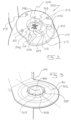
Figure 2 is a perspective view of an underside of a filter basket showing a guide or pilot. -
Figure 3 is a perspective view of a platform of a coffee making machine. -
Figure 4 is a cross-sectional view through a filter basket, platform and actuator. -
Figure 5 is a cross-sectional view through a filter basket, platform and actuator. -
Figure 6 is a cross-sectional view through a filter basket, platform and actuator. -
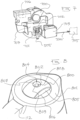
Figure 7 a perspective view of a motorised cam. -
Figure 8 is a perspective view of a carafe and lid. -
Figure 9 is an underside perspective view of a filter basket and drip stop valve. -
Figure 10 is a perspective view of a platform and actuator. -
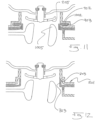
Figure 11 is a cross sectional view of an interlocking of a filter basket with a platform under which is an actuator. -
Figure 12 is a cross sectional view of a platform and filter basket. -
Figure 13 is a perspective view, partially sectioned, of a drip stop valve. - As shown in
Figure 1 , a drip filter coffee machine 100 has amain body 101. - The
main body 101 has a base 102 that is adapted to receive acarafe 103. Thecarafe 103 is insertable and removable below afixed platform 104 that forms part of themain body 101. - The
main body 101 may support a pivoting or preferably, a fixedlid 105. In some embodiments, the lid may have an internal water discharge head 106 that cooperates with asupply line 107 that carries heated water from within themain body 101. In some embodiments, vertical height of the main body's water reservoir and the upper surface of thelid 105 are all the same. In other embodiments, the discharge head is carried by themain body 101, not the lid. - When the
lid 105 or discharge head 106 is in place, thefilter basket 111 can be removed from theplatform 104. - Both the
carafe 103 and thefilter basket 111 havehandles Figure 1 , the carafe'shandle 112, during insertion, use and removal, may be situated in any angular orientation that is not prohibited by themain body 101. This represents an angular travel or sweep of about 270 degrees. The technology described herein will show how a filter basket with a drip stop valve can also be inserted so as to cooperate with the carafe, over a range of angular orientations (of 20 about 270 degrees) 114, that is, only practically limited by the presence of themain body 101 or other obstructions (like a user's hand). - As shown in
Figures 2 and 3 , theunderside 200 of thefilter basket 201 has arecess 202 forming a ramp or tapered pilot into acentral bore 203. Therecess 202 includes a flat orhorizontal guide surface 217 that defines oneedge 218 of thebore 203. Theflat guide surface 217 is intended to contact theupper rim 307 of thecoupling 303, and theramp 202 is intended to contact the tapered or chamferededge 302 of the platform'supper rim 302. Thesidewalls bore 203 and guide thecoupling 303 into position. The lower or contactingsurface 205 of the filter basket's discharge or drip stop valve is located within thebore 203. Thevalve surface 205 is preferably a section of a sphere or otherwise smoothly curved. Thesurface 205 has acentral opening 206 through which brewed coffee is discharged out of thefilter basket 201. In this example, the discharged stream of coffee is centralised and regularised by way of an array offins 207 that intersect along acommon axis 208 that is central to thefins 207. The discharge flow forms around and along thisaxis 208. - The lower
most surface 204 of the filter basket may include an array of locating features 212. In this example, each locating feature is a protruding spheroidal or roundedtip 213. Thetip 213 may be retractable. In this example, thefeatures 212 are three in number and located around a common radius from theaxis 208. All threefeatures 212 engage and cooperate with features on the upper surface of theplatform 104. - As shown in
Figure 3 , theplatform 104 has anupper surface 300 in which is formed acircumferential groove 301. The platform'supper rim 302 is radiused or tapered to lead into thegroove 301. The lower part of the rim may also be tapered. A raised male coupling portion orrim 303 is raised above the level of the groove enough to be engaged circumferentially and located by thebore 203 in the underside of the filter basket when the outer part of thecoupling portion 303 contacts or is stopped by thebore 203. This happens as the filter basket is inserted. - The
male coupling feature 303 has a central throughopening 305 that receives the upper part of the drip stop valve'sactuator 306. When theactuator 306 is elevated, it acts against thecontact surface 205 of the drip stop valve, allowing fluid to flow through it. - As shown in
Figure 4 , theactuator 400 is supported for pivoting motion around a retainingpin 401. Depressing thedistal end 402 of the actuator causes it to pivot and contact the underside 403 of the basket'sdischarge valve 405. Thedischarge valve 405 is located at the lowest point of the basket'sinternal filter chamber 406. Thevalve 405 is biased downward (toward the actuator) by aspring 407. When the movingvalve element 408 is lifted by the actuator, brewed coffee flows past the small valve stem orshaft 410 and through a central discharge opening 409 in the actuator. Theshaft 410 is supported for sliding in thelarger opening 411 in thefilter basket compartment 412 by an array ofradial fins 413. - As shown in
Figure 5 , lifting of thevalve body 408 unseats aseal 501 that admits brewed coffee into theopenings 502 in the valve body. In this example, the lifting power is provided by thelinear motion 503 of a tab ormechanical finger 505. Thefinger 505 may be driven by amotorised cam 504 as shown inFigure 7 , or otherwise. -
Figure 5 also illustrates that the protruding locating features 506 may havetips 507 that are biased into position by acompression spring 508 captured between thetip 507 and a portion of thefilter basket 509. Also illustrated are the chamfers, taper or curvature of the upper andlower edges platform 104, where it contacts the filter basket, on insertion. - As shown in
Figures 4, 5 and 6 , the working head of theactuator 510 comprises a toroidal or donut-like structure having acentral passageway 511. Thepassageway 511 is either generally cylindrical or tapered toward a wider opening at the discharge end of thepassageway 511. The upper and lower ends of thepassageway 511 are sharply radiused 512, 513 and more sharply radiused than the remainder of theexterior 514 of thehead 510. This acts to collect and manage leakage. The diameter of the upper extent ofpassageway 511 is slightly offset and wider than thedischarge passageway 502. This takes into account the motion of the actuator and minimizes the possibility of the discharge stream taking a path over theexterior 514. The parallel or cylindrical walls of thepassageway 511 together with theradiused edges head 510, particularly in the central flow path. - The
radius 512 is smooth enough to make acceptable sliding engagement with thecontact surface 802 of the carafe that drives it into engagement with the drip stop valve. Similarly, theupper edge 513 of the head is smooth enough to make sliding engagement with theunder surface 404 of thedrip stop valve 405 andpilot 202. - As shown in
Figure 6 , aninsulated carafe 600 has an insultedlid 601. The lid has a springbiased contact surface 602 that is able to drive theactuator 603 into thedrip stop valve 604. In preferred embodiments, it is desirable to have the upper or extended position of the contactingsurface 602 terminate at a vertical height that is higher than the underside surface 605 of the fixedplatform 104. The biased contactingsurface 602 reciprocates to better pass below theplatform 104 and then extend upwards into the throughopening 305 to contacthead 510. The undersidefront edge 606 of the platform is chamfered to guide the contactingsurface 602. - In order to both pass under the
platform 104 and ultimately achieve a location above the lower surface of it 605, thelids contacting surface 602 is biased upward by asecond compression spring 609. The spring force of thesecond spring 609 must be enough to overcome the spring force of thespring 407 that maintains the closure of thedrip stop valve 604. However, it must not be so strong as to interfere with the insertion of the carafe into its fill position. - As shown in
Figure 7 , thefinger 505 that drives thatactuator 400 may be driven or propelled by a motorised, rotating cam 700. Thefinger 505 is trapped for reciprocal motion and biased away from its extended position by acompression spring 701. In preferred embodiments, the head 702 of thefinger 701 or the cam itself 700 interacts with aswitch 703 or sensor that transmits a signal 704 to the device'sprocessor 705. The switch orsensor 703 provides information to the processor about the location of the actuator. Theprocessor 705 also controls the motion of the cam 700 by transmitting power signals to anelectric motor 706 located within thehousing 707 that supports the cam 700, the finger 500 and optionally, the switch orsensor 703. - As shown in
Figure 8 , the contactingsurface 800 of the carafe'slid 801 has a spherical or otherwise curvedupper surface 802. Theentire surface 802 drops away from a high point represented by animaginary diameter 803 that encircles aninlet opening 804. In this example, thecontact bumper 800 hasparallel sidewalls 805 that allow it to reliably reciprocate with a flat-sided slot 806 formed in the lid. Thesidewalls 805 also conceal thesecond spring 609 from sight. - The
inlet opening 804 consists of a radius or smoothlycurved funnel 807. Thefunnel 807 falls away from thediameter 803 and blends into a centrally located, straightvertical passageway 808 that leads into the interior of the carafe. The spherical or curved configuration of theupper surface 802 allows the carafe to be inserted into engagement with theactuator 400 in any angular orientation of the carafe'shandle 112 with respect to themain body 101. -
Figures 9 and 10 illustrate an alternate embodiment of an engagement between aplatform 104 and afilter basket 901. In the example shown inFigures 2 and 3 , in addition to the lid there is no mechanical engagement or interference between the filter basket and the platform that would inhibit unwanted vertical motion of the filter basket once it is in place. In the examples ofFigures 9 and 10 , theunderside 900 of thefilter basket 901 has a lip oroverhang 902 that creates a partiallycircumferentially slot 903. Theslot 903 created by theoverhang 902 receives acircular head 1000. As shown inFigure 10 , thehead 1000 is elevated above the upper surface of the platform by acylindrical neck 1001 and may be removable. Theouter rim 1002 is radially inward of thecircumferential groove 1003. Thehead 1000 has acentral opening 1004 through which the dripstop valve actuator 1005 can be brought into and out of engagement with the contact surface of thedrip stop valve 205. - The
ramp 904 leads to aflat guide portion 905 that is flush with therim 906 of thebore 907. This pilot area may include lateral narrowingguide surfaces 908 for directing theouter rim 1002 into theslot 903. When coupled, the peripheral wall of theslot 903 receives and may contact therim 1002. As with the embodiments inFigures 2 and 3 , theramp surface 904 cooperates with the tapered or chamferededge 1006 of the platform, and theflat guide portion 905 cooperates with the upward facing surface ofhead 1000. - As shown in
Figure 11 , therim 1002 of the male coupling feature is seen as carried by theslot 903 formed by the overhangingrim 902 shown inFigures 9 and 10 . -
Figure 12 illustrates the alternate arrangement ofFigure 2 and 3 where the uprightcylindrical coupling feature 303 is nested within thebore 203 on the underside of thefilter basket 201 as suggested byFigures 2 and 3 . -
Figure 13 illustrate a drip stop valve 1300 for afilter basket 1301. In this embodiment, theunderside 1302 of the filter basket has acentral opening 1304 surrounded by anelevated sealing rim 1303. The reciprocating sealing element 1305 has a small central shaft 1306 that supports an array of (in this example) fourspacer fins 1307. Thefins 1307 guide the element 1305 for motion within therim 1303. The fins also increase the surface area in the central flow region to encourage wicking close to the shaft 1306. The lower edges of thefins 1313 may be tapered. Lower ends of thefins 1307 affix the valve's circular contact surface 1308 to the shaft 1306. An upper head of the shaft 1306 has acircumferential groove 1309 that carries a polymeric seal 1308. The lowest tip 1311 of the shaft 1306 protrudes from an underside of thevalve element 1312 to form a wick and define a central wicking axis. The sealing element 1305 is biased downward (toward the actuator) by acompression spring 1310 carried between the contacting surface 1308 and the underside of thefilter compartment 1302. Unless acted on by an actuator or a vessel, thespring 1310 drives the seal 1308 into engagement with the sealingrim 1303. When thereciprocating valve element 1312 is lifted, liquid flows though over therim 1303 forming separate flow regions that recombine into a single stream once the liquid flows past thefins 1307. - Although the invention has been described with reference to specific examples, it will be appreciated by those skilled in the art that the invention may be embodied in many other forms.
- As used herein, unless otherwise specified, the use of the ordinal adjectives "first", "second", "third", etc., to describe a common object, merely indicate that different instances of like objects are being referred to, and are not intended to imply that the objects so described must be in a given sequence, either temporally, spatially, in ranking, or in any other manner.
- Reference throughout this specification to "one embodiment" or "an embodiment" or "example" means that a particular feature, structure or characteristic described in connection with the embodiment is included in at least one embodiment of the present invention. Thus, appearances of the phrases "in one embodiment" or "in an example" in various places throughout this specification are not necessarily all referring to the same embodiment or example, but may. Furthermore, the particular features, structures or characteristics may be combined in any suitable manner, as would be apparent to one of ordinary skill in the art from this disclosure, in one or more embodiments.
- Similarly, it should be appreciated that in the above description of exemplary embodiments of the invention, various features of the invention are sometimes grouped together in a single embodiment, figure, or description thereof for the purpose of streamlining the disclosure and aiding in the understanding of one or more of the various inventive aspects. This method of disclosure, however, is not to be interpreted as reflecting an intention that the claimed invention requires more features than are expressly recited in each claim. Rather, as the following claims reflect, inventive aspects lie in less than all features of a single foregoing disclosed embodiment. Any claims following the Detailed Description are hereby expressly incorporated into this Detailed Description, with each claim standing on its own as a separate embodiment of this invention.
- Furthermore, while some embodiments described herein include some but not other features included in other embodiments, combinations of features of different embodiments are meant to be within the scope of the invention, and form different embodiments, as would be understood by those in the art. For example, in the following claims, any of the claimed embodiments can be used in any combination.
- Thus, while there has been described what are believed to be the preferred embodiments of the invention, those skilled in the art will recognize that other and further modifications may be made thereto without departing from the scope of the invention, and it is intended to claim all such changes and modifications as fall within the scope of the invention.
- While the present invention has been disclosed with reference to particular details of construction, these should be understood as having been provided by way of example and not as limitations to the scope of the invention.
- Aspects of the invention are set forth below.
- Aspect 1. A coffee machine having a base, a body extending upwardly from the base, a platform having an upward facing surface and a coupling portion, the platform being supported by and extending outwardly from the body, and a filter basket, wherein the filter basket includes:
- a downward facing bottom surface supported on the upward facing surface, a recess located in the bottom surface of the filter basket to receive the coupling portion of the platform;
- at least one downwardly facing locating feature cooperating with the platform to aid alignment of the filter basket with the platform; and wherein
- the upward facing surface of the platform includes at least one upwardly facing locating feature engaged with the downwardly facing location feature to at least aid in locating the filter basket in an engaged position with the coupling portion.
- Aspect 2. The coffee machine of aspect 1, wherein the downward facing bottom surface of the filter basket has two guide surfaces that taper toward the recess to guide the filter basket into the engage position with the platform.
-
Aspect 3. The coffee machine of aspect 2, further including a generally upright axis passing through a central portion of the coupling portion with the coupling portion of the platform aligned on the axis and with the recess when the locating features are engaged. -
Aspect 4. The coffee machine ofaspect 3, wherein the coupling portion has a rim extending upwardly from the platform that contacts at least one of the two guide surfaces during engagement of the filter basket with the platform. -
Aspect 5. The coffee machine ofaspect 4, wherein the filter basket is locatable in the engaged position by moving the filter basket toward the generally upright axis from a radial angle of at least 180 degrees relative to the generally upright axis. - Aspect 6. A coffee machine having a base, a body extending upwardly from the base, a platform having an upwardly facing surface, the platform being supported by and extending outwardly from the body, and a filter basket, wherein the filter basket includes:
- a valve selectively operable to allow liquid coffee to exit the filter basket; and
- the platform including a lever, said lever having a central passageway; and wherein
- the lever is operable to open the valve to allow liquid coffee to exit from the filter basket through the central passageway of the lever.
- Aspect 7. The coffee machine of aspect 6, wherein the valve has a central pin, the pin having a fin-like structure, to encourage wicking of the liquid coffee, as the liquid coffee passes through the valve and though the central passageway of the lever.
- Aspect 8. The coffee machine of aspect 7, wherein the lever has a proximal end and a distal end relative to the coffee machine, the proximal end having a point of rotation and the distal end having a toroidal shaped head surrounding the central passageway to allow liquid coffee to pass though the central passageway of the lever.
- Aspect 9. The coffee machine of aspect 8, wherein the valve is spring biased to a closed position preventing liquid coffee from exiting the filter basket.
- Aspect 10. The coffee machine of aspect 9, wherein the head of the lever is actuatable to contact the valve to overcome the spring bias and open the valve, thereby allowing liquid coffee to pass through the central passageway of the lever.
- Aspect 11. The coffee machine of aspect 10, wherein the valve has an axis that is aligned with a central axis of the central passageway, when the filter basket is in an engaged position on the platform.
- Aspect 12. A coffee machine having a base, a body extending upwardly from the base, a platform having an upward facing surface and a coupling portion, the platform being supported by and extending outwardly from the body, a filter basket and a carafe having a lid with an upwardly forced portion, wherein the filter basket includes:
- a downward facing bottom surface supported on the upward facing surface of the platform;
- a recess located in the bottom surface of the filter basket to receive the coupling portion of the platform;
- a valve to prevent or allow liquid coffee exiting from the filter basket; and
- the platform including a lever to open the valve and allow liquid coffee to exit from the filter basket and drip though a central passageway of the lever; and wherein
- the upwardly forced portion of the lid reciprocates downwardly under interference with the platform and upwardly once the carafe is in an engaged position relative to the platform.
- Aspect 13. The coffee machine of aspect 12, wherein the valve is spring biased to a closed position.
- Aspect 14. The coffee machine of aspect 13, wherein the upwardly forced portion of the lid is spring biased in to open position.
- Aspect 15. The coffee machine of aspect 14, wherein the spring bias of the upwardly forced portion forces the lever to contact and open the valve of the filter basket when the carafe is in the engaged position.
- Aspect 16. The coffee machine of aspect 15, wherein the spring bias of the upwardly forced portion is greater than the spring bias of the valve.
- Aspect 17. The coffee machine of aspect 16, wherein in the engaged position, the filter basket valve, the central passageway of the lever and the upwardly forced portion of the carafe lid are aligned so that the liquid coffee from the filter basket can flow through the central passageway and the carafe lid and into the carafe.
Claims (8)
- A filter basket for use with a coffee machine, the filter basket comprising:a valve selectively operable to allow liquid coffee to exit the filter basket,wherein the valve is spring biased to a closed position preventing liquid coffee from exiting the filter basket.
- The filter basket of claim 1, wherein the valve has a central pin, the pin having a fin-like structure, to encourage wicking of the liquid coffee, as the liquid coffee passes through the valve.
- The filter basket of claim 2, wherein an actuator of the coffee machine is operable to open the valve to allow liquid coffee to exit from the filter basket through a central passageway of the actuator.
- The filter basket of claim 2, wherein a head of the actuator is actuatable to contact the valve to overcome the spring bias and open the valve, thereby allowing liquid coffee to pass through the central passageway of the lever.
- The filter basket of claim 2, wherein the fin-like structure of the pin comprises an array of fins that intersect along a common axis that is central to the fins.
- The filter basket of claim 5, wherein lower edges of the fins are tapered.
- The filter basket of claim 1, wherein an underside of the filter basket has an opening surrounded by a sealing rim, and
wherein, when the valve is opened, the liquid coffee flows through over the rim. - The filter basket of claim 2, wherein a lowest tip of the central pin protrudes from an underside of the valve.
Applications Claiming Priority (3)
| Application Number | Priority Date | Filing Date | Title |
|---|---|---|---|
| AU2017902537A AU2017902537A0 (en) | 2017-06-30 | Drip Filter Coffee Machine | |
| EP18823507.1A EP3644799B1 (en) | 2017-06-30 | 2018-05-31 | Drip filter coffee machine |
| PCT/AU2018/000083 WO2019000012A1 (en) | 2017-06-30 | 2018-05-31 | Drip filter coffee machine |
Related Parent Applications (1)
| Application Number | Title | Priority Date | Filing Date |
|---|---|---|---|
| EP18823507.1A Division EP3644799B1 (en) | 2017-06-30 | 2018-05-31 | Drip filter coffee machine |
Publications (2)
| Publication Number | Publication Date |
|---|---|
| EP4434411A2 true EP4434411A2 (en) | 2024-09-25 |
| EP4434411A3 EP4434411A3 (en) | 2024-12-18 |
Family
ID=64740267
Family Applications (2)
| Application Number | Title | Priority Date | Filing Date |
|---|---|---|---|
| EP18823507.1A Active EP3644799B1 (en) | 2017-06-30 | 2018-05-31 | Drip filter coffee machine |
| EP24194179.8A Pending EP4434411A3 (en) | 2017-06-30 | 2018-05-31 | Drip filter coffee machine |
Family Applications Before (1)
| Application Number | Title | Priority Date | Filing Date |
|---|---|---|---|
| EP18823507.1A Active EP3644799B1 (en) | 2017-06-30 | 2018-05-31 | Drip filter coffee machine |
Country Status (5)
| Country | Link |
|---|---|
| US (2) | US11812886B2 (en) |
| EP (2) | EP3644799B1 (en) |
| CN (3) | CN119655611A (en) |
| AU (1) | AU2018293907B2 (en) |
| WO (1) | WO2019000012A1 (en) |
Families Citing this family (6)
| Publication number | Priority date | Publication date | Assignee | Title |
|---|---|---|---|---|
| DE102020124966A1 (en) * | 2020-09-24 | 2022-03-24 | 10X Innovation GmbH & Co. KG | Filter holder and coffee maker |
| USD1007216S1 (en) * | 2021-12-02 | 2023-12-12 | Samsung Electronics Co., Ltd. | Coffee machine |
| US20240081575A1 (en) * | 2022-09-12 | 2024-03-14 | Helen Of Troy Limited | Coffee maker drip stop mechanism |
| WO2025155321A1 (en) | 2024-01-18 | 2025-07-24 | Sharkninja Operating Llc | Suggesting coffee bean grind size for beverage machines |
| WO2025155323A1 (en) | 2024-01-18 | 2025-07-24 | Sharkninja Operating Llc | Preventing coffee bean grinder jamming |
| US12369744B1 (en) | 2024-01-18 | 2025-07-29 | Sharkninja Operating Llc | Preparation of beverage machines for cold beverage brewing |
Family Cites Families (26)
| Publication number | Priority date | Publication date | Assignee | Title |
|---|---|---|---|---|
| US4191100A (en) * | 1976-11-15 | 1980-03-04 | North American Systems, Inc. | Brewing apparatus for coffee and the like |
| DE8702616U1 (en) * | 1987-02-20 | 1987-04-16 | Robert Krups Stiftung & Co KG, 5650 Solingen | Electrically operated coffee machine |
| US5133247A (en) * | 1991-01-11 | 1992-07-28 | Mr. Coffee, Inc. | Coffee maker |
| NL9302082A (en) | 1993-11-30 | 1995-06-16 | Smitdesign Bv | Coffee maker with removable anti-leakage filter. |
| US6035761A (en) * | 1996-09-18 | 2000-03-14 | Food Equipment Technologies Company, Inc. | Brewing system with hot water holding tank flushing apparatus and holding tank preheating method |
| US5910205A (en) * | 1997-07-24 | 1999-06-08 | Cafe 98 Industries Limited | Brew basket for coffee-making machine |
| US5880441A (en) * | 1997-11-12 | 1999-03-09 | National Presto Industries, Inc. | Microwave beverage maker apparatus and method |
| US5957036A (en) * | 1998-10-16 | 1999-09-28 | Hamilton Beach/Proctor-Silex, Inc. | Coffee maker with a pause-serve mechanism |
| JP2007054604A (en) | 2005-07-25 | 2007-03-08 | Izumi Products Co | Beverage maker |
| EP1808110A1 (en) * | 2006-01-17 | 2007-07-18 | Wen-Ching Lee | Automatic filter tea/coffee maker |
| CA2641062C (en) * | 2006-03-23 | 2014-08-12 | Breville Pty Limited | Drip filter coffee maker |
| US20100018403A1 (en) * | 2006-10-24 | 2010-01-28 | Breville Pty Limited | Tea Maker |
| US7836820B2 (en) * | 2007-09-19 | 2010-11-23 | Sunbeam Products, Inc. | Brewing device having a delayed release mechanism |
| US9167932B2 (en) * | 2009-09-28 | 2015-10-27 | Food Equipment Technologies Company, Inc. | Dual-purpose brewer and brew basket and method of brewing |
| US8904923B2 (en) * | 2011-12-27 | 2014-12-09 | Whirlpool Corporation | Coffee maker supporting single serving and multiple serving operation |
| US8850958B2 (en) * | 2011-12-27 | 2014-10-07 | Whirlpool Corporation | Coffee maker with drip stop supporting single serve and carafe operation |
| DE202012103158U1 (en) | 2012-08-21 | 2013-11-25 | Melitta Europa Gmbh & Co. Kg | coffee machine |
| CN105188486B (en) * | 2013-03-20 | 2019-03-19 | 皇家飞利浦有限公司 | Device for preparing hot beverages with automatic power-off mechanism |
| CN104545446B (en) * | 2013-10-18 | 2017-07-14 | 新宝基电器(深圳)有限公司 | Apparatus for automatically making tea or beverage using boiled water and method for pouring |
| CN106998936A (en) * | 2014-08-20 | 2017-08-01 | 布瑞威利私人有限公司 | coffee maker |
| US20160120359A1 (en) * | 2014-11-04 | 2016-05-05 | Focus Products Group International, Llc | Drip Beverage Machine with Brew and Steep Feature |
| CN105982553A (en) * | 2015-02-11 | 2016-10-05 | 谊丰实业有限公司 | Novel flush handle |
| JP6285892B2 (en) * | 2015-05-13 | 2018-02-28 | 象印マホービン株式会社 | Beverage extractor |
| CN205072683U (en) * | 2015-08-03 | 2016-03-09 | 姜明坤 | Coffee water clock cup |
| DE202017100295U1 (en) * | 2017-01-20 | 2017-01-30 | Seb S.A. | Filter coffee machine with a drip-stop device |
| US10702092B2 (en) * | 2017-03-17 | 2020-07-07 | Whirlpool Corporation | Coffee maker with multiple brewing methods |
-
2018
- 2018-05-31 CN CN202411903331.6A patent/CN119655611A/en active Pending
- 2018-05-31 EP EP18823507.1A patent/EP3644799B1/en active Active
- 2018-05-31 US US16/627,751 patent/US11812886B2/en active Active
- 2018-05-31 CN CN202210623983.9A patent/CN114947517B/en active Active
- 2018-05-31 AU AU2018293907A patent/AU2018293907B2/en active Active
- 2018-05-31 WO PCT/AU2018/000083 patent/WO2019000012A1/en not_active Ceased
- 2018-05-31 EP EP24194179.8A patent/EP4434411A3/en active Pending
- 2018-05-31 CN CN201880033740.1A patent/CN110662466B/en active Active
-
2023
- 2023-10-09 US US18/377,889 patent/US20240038303A1/en active Pending
Also Published As
| Publication number | Publication date |
|---|---|
| WO2019000012A1 (en) | 2019-01-03 |
| US20240038303A1 (en) | 2024-02-01 |
| EP4434411A3 (en) | 2024-12-18 |
| AU2018293907B2 (en) | 2023-11-23 |
| AU2018293907A1 (en) | 2019-11-07 |
| US20200121113A1 (en) | 2020-04-23 |
| CN114947517B (en) | 2025-01-07 |
| CN110662466B (en) | 2022-06-14 |
| CN119655611A (en) | 2025-03-21 |
| US11812886B2 (en) | 2023-11-14 |
| EP3644799B1 (en) | 2024-08-28 |
| EP3644799A4 (en) | 2021-03-17 |
| EP3644799A1 (en) | 2020-05-06 |
| CN110662466A (en) | 2020-01-07 |
| CN114947517A (en) | 2022-08-30 |
Similar Documents
| Publication | Publication Date | Title |
|---|---|---|
| US20240038303A1 (en) | Drip filter coffee machine | |
| JP5373977B2 (en) | Tea maker with closable pouring opening | |
| EP1648273B1 (en) | Juicer | |
| RU2586983C2 (en) | Improved machine for beverage preparation | |
| EP3185729B1 (en) | Citrus lid for blender | |
| EP2220977A2 (en) | Bottle stopper | |
| RU2570370C2 (en) | Device, system and method of preparing beverage suitable for consumption, from capsule | |
| EP2087818B1 (en) | Filter holder for a coffee machine | |
| RU2604177C2 (en) | Improving relating to beverage preparation machines | |
| JP2009537239A (en) | Coffee and tea pods | |
| US9332875B2 (en) | Coffee maker with single serve setting | |
| JP2015535720A (en) | Extraction unit having shiftable cartridge receivers of multiple sizes | |
| US10420362B2 (en) | Juicer | |
| WO2005041732A1 (en) | Citrus reamer and press | |
| US11116353B2 (en) | Coffee machine | |
| ES2308115T3 (en) | MACHINE FOR THE PREPARATION OF DRINKS. | |
| CN215016174U (en) | Beverage preparation machine | |
| US20040200357A1 (en) | Coffee brewing apparatus | |
| WO2018039346A1 (en) | Milk frother | |
| CA2424479C (en) | Coffee brewing apparatus | |
| EP2919916B1 (en) | Container cleaner with timing mechanism | |
| AU2004253180B2 (en) | Juicer | |
| CA2530865C (en) | Juicer | |
| JPS58430Y2 (en) | Seal structure of coffee maker with coffee mill | |
| HK1130168A1 (en) | Filter holder for a coffee machine |
Legal Events
| Date | Code | Title | Description |
|---|---|---|---|
| PUAI | Public reference made under article 153(3) epc to a published international application that has entered the european phase |
Free format text: ORIGINAL CODE: 0009012 |
|
| STAA | Information on the status of an ep patent application or granted ep patent |
Free format text: STATUS: THE APPLICATION HAS BEEN PUBLISHED |
|
| AC | Divisional application: reference to earlier application |
Ref document number: 3644799 Country of ref document: EP Kind code of ref document: P |
|
| AK | Designated contracting states |
Kind code of ref document: A2 Designated state(s): AL AT BE BG CH CY CZ DE DK EE ES FI FR GB GR HR HU IE IS IT LI LT LU LV MC MK MT NL NO PL PT RO RS SE SI SK SM TR |
|
| PUAL | Search report despatched |
Free format text: ORIGINAL CODE: 0009013 |
|
| AK | Designated contracting states |
Kind code of ref document: A3 Designated state(s): AL AT BE BG CH CY CZ DE DK EE ES FI FR GB GR HR HU IE IS IT LI LT LU LV MC MK MT NL NO PL PT RO RS SE SI SK SM TR |
|
| RIC1 | Information provided on ipc code assigned before grant |
Ipc: A47J 31/057 20060101AFI20241112BHEP |
|
| STAA | Information on the status of an ep patent application or granted ep patent |
Free format text: STATUS: REQUEST FOR EXAMINATION WAS MADE |
|
| 17P | Request for examination filed |
Effective date: 20250618 |