EP4432793A2 - Equipment rail with finger mounting bracket - Google Patents
Equipment rail with finger mounting bracket Download PDFInfo
- Publication number
- EP4432793A2 EP4432793A2 EP24159823.4A EP24159823A EP4432793A2 EP 4432793 A2 EP4432793 A2 EP 4432793A2 EP 24159823 A EP24159823 A EP 24159823A EP 4432793 A2 EP4432793 A2 EP 4432793A2
- Authority
- EP
- European Patent Office
- Prior art keywords
- equipment
- equipment rail
- rail
- mounting bracket
- section
- Prior art date
- Legal status (The legal status is an assumption and is not a legal conclusion. Google has not performed a legal analysis and makes no representation as to the accuracy of the status listed.)
- Granted
Links
Images




Classifications
-
- H—ELECTRICITY
- H05—ELECTRIC TECHNIQUES NOT OTHERWISE PROVIDED FOR
- H05K—PRINTED CIRCUITS; CASINGS OR CONSTRUCTIONAL DETAILS OF ELECTRIC APPARATUS; MANUFACTURE OF ASSEMBLAGES OF ELECTRICAL COMPONENTS
- H05K7/00—Constructional details common to different types of electric apparatus
- H05K7/14—Mounting supporting structure in casing or on frame or rack
- H05K7/1485—Servers; Data center rooms, e.g. 19-inch computer racks
- H05K7/1488—Cabinets therefor, e.g. chassis or racks or mechanical interfaces between blades and support structures
- H05K7/1489—Cabinets therefor, e.g. chassis or racks or mechanical interfaces between blades and support structures characterized by the mounting of blades therein, e.g. brackets, rails, trays
-
- H—ELECTRICITY
- H04—ELECTRIC COMMUNICATION TECHNIQUE
- H04Q—SELECTING
- H04Q1/00—Details of selecting apparatus or arrangements
- H04Q1/02—Constructional details
- H04Q1/06—Cable ducts or mountings specially adapted for exchange installations
-
- H—ELECTRICITY
- H05—ELECTRIC TECHNIQUES NOT OTHERWISE PROVIDED FOR
- H05K—PRINTED CIRCUITS; CASINGS OR CONSTRUCTIONAL DETAILS OF ELECTRIC APPARATUS; MANUFACTURE OF ASSEMBLAGES OF ELECTRICAL COMPONENTS
- H05K7/00—Constructional details common to different types of electric apparatus
- H05K7/14—Mounting supporting structure in casing or on frame or rack
- H05K7/1485—Servers; Data center rooms, e.g. 19-inch computer racks
- H05K7/1488—Cabinets therefor, e.g. chassis or racks or mechanical interfaces between blades and support structures
- H05K7/1491—Cabinets therefor, e.g. chassis or racks or mechanical interfaces between blades and support structures having cable management arrangements
-
- H—ELECTRICITY
- H05—ELECTRIC TECHNIQUES NOT OTHERWISE PROVIDED FOR
- H05K—PRINTED CIRCUITS; CASINGS OR CONSTRUCTIONAL DETAILS OF ELECTRIC APPARATUS; MANUFACTURE OF ASSEMBLAGES OF ELECTRICAL COMPONENTS
- H05K7/00—Constructional details common to different types of electric apparatus
- H05K7/18—Construction of rack or frame
- H05K7/183—Construction of rack or frame support rails therefor
Definitions
- the present disclosure relates to a data center cabinet, and more particularly to an equipment rail with a finger mounting bracket installed in a data center cabinet.
- a data center cabinet 20 includes a plurality of equipment rails 50.
- the equipment rails 50 include gussets 60 and a stiffening rib 62 that extends the length of the equipment rail 50.
- the gussets 60 and the stiffening rib 62 are welded in place to provide the equipment rails 50 with more rigidity when enduring horizontal forces in the front to back direction.
- the equipment rails 50 include a plurality of diamond shaped openings 54 that are punched into the equipment rails 50.
- the diamond shaped openings 54 are designed to receive the cable management fingers 70 ( FIG. 3 ).
- the stiffening rib 62 is welded to the back of the equipment rail 50.
- the stiffening rib 62 extends the full height of the equipment rail 50.
- a bulb seal 66 extending the full height of the equipment rail 50 is installed on the stiffening rib 62.
- the bulb seal 66 blocks the diamond shaped openings 54 that are not occupied with the cable management fingers 70.
- the bulb seal 66 is required to block unwanted air flowing through the diamond shaped openings 54 in the equipment rail 50 when the cable management fingers 70 are not required.
- the present disclosure is directed to an equipment rail for mounting in a data center cabinet.
- the equipment rail includes a first section and a second section.
- a finger mounting bracket is secured to the second section.
- the finger mounting bracket has a first member with sidewalls and a second member parallel to the first member. The distal ends of the sidewalls engage the equipment rail forming an open area between the first member and the equipment rail.
- the first member of the finger mounting bracket has a plurality of diamond openings for receiving a cable management accessory to route cables in the data center cabinet.
- FIG. 5 illustrates a data center cabinet 100 with equipment rails 120.
- the data center cabinet 100 is defined by a frame 102 with two front vertical posts 104, two back vertical posts 106, top side to side beams 108, bottom side to side beams 110, and a plurality of front to back beams 112.
- the equipment rails 120 are installed at the front and back of the cabinet 100 and on each side of the cabinet 100.
- the equipment rails 120 are L-shaped with a first section 122 secured to the front to back beams 112 and a second section 124.
- the second section 124 includes a plurality of openings 126 extending the height of the equipment rail 120 for receiving the rack mounted equipment (not illustrated).
- the equipment rail 120 includes a plurality of beads 128, 130 pressed into the equipment rail 120.
- the pressed in beads 128 extend horizontally in the first section 122 and the second section 124 of the equipment rail 120.
- the pressed in bead 130 extends vertically the full height of the equipment rail 120 in the second section 124.
- the pressed in beads 128, 130 add rigidity to the equipment rail 150 when subject to horizontal forces in the front to back direction.
- the pressed in beads 128, 130 are an alternative to the welded gussets 60 in the prior art equipment rails 50 as illustrated in FIGS. 1-4 .
- the pressed in beads 128, 130 eliminate the need for welding extra components to the equipment rail.
- the vertical pressed in bead 130 also eliminates the need for the stiffening rib 62 that was welded to the prior art equipment rails 50 illustrated in FIGS. 1-4 .
- the equipment rail 120 includes a plurality of vertical slots 132 and screw hole openings 134.
- a finger mounting bracket 150 is positioned to be mounted to the equipment rail 120.
- the finger mounting bracket 150 is designed to receive cable management fingers 170 for routing cables.
- the finger mounting bracket 150 includes a first member 152 with sidewalls 154, 156 and a second member 162 parallel to the first member 152.
- the second member 162 extends from a distal end of one of the side walls 154.
- a plurality of hooks 158 extend from the distal end of the opposite side wall 156.
- the first member 152 includes a plurality of diamond shaped openings 160 for receiving cable management fingers 170, or other cable management accessory.
- the second member 162 includes a plurality of slots 164 for receiving fasteners to mount the finger mounting bracket 150 to the equipment rail 120.
- the hooks 158 extending from the finger mounting bracket 150 align with the vertical slots 132 in the equipment rail 120.
- the slots 164 in the second member 162 align with the screw hole openings 134 in the equipment rail 120.
- the hooks 158 extending from the finger mount bracket 150 are installed through the vertical slots 132 and the slots 164 and holes 134 are aligned to receive a screw (not illustrated), or other fastener, to secure the finger mounting bracket 150 to the equipment rail 120.
- the distal ends of the side walls 154, 156 extending from the first member 152 engage the equipment rail 120 forming an open area 168 between the first member 150 and the equipment rail 120.
- cable management fingers 170 are mounted in the diamond shaped openings 160 with the mounting member on the back side of the cable management fingers 170 disposed within the diamond shaped opening 160 between the finger mounting bracket 150 and the equipment rail 120.
- the diamond shaped openings 160 are blocked by the equipment rail 120 and the vertical bead pressed 130 into the equipment rail 120.
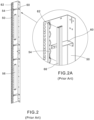
- the equipment rail 120 of the present disclosure no longer includes the diamond shaped openings 54 for receiving the cable management fingers. As a result, removing the diamond shaped openings 54 eliminates the need for the bulb seal 66 used to block air potentially bypassed through the diamond shaped openings 54 in the prior art equipment rails 50 (see FIG. 2A ).
- the equipment rail 120 also includes an improved rack unit cover 180.
- FIG. 10 illustrates the cover positioned to be installed on the equipment rail 120.
- FIG. 11 illustrates the covers 180 of the present disclosure secured over the 1 RU openings 136.
- equipment rails It is common for equipment rails to include a vertical 1 RU (rack unit) opening 136 within the equipment rail 120.
- the 1 RU openings 136 are designed for receiving pieces of equipment or patch panels that are compatible with the 1 RU openings 136 per EIA/ECA-301-E standards. When the 1 RU openings 136 are not in use, they are covered with metal plates 180 to block air flow. As illustrated in the prior art cabinet of FIG.
- the covers 80 are only mounted to the equipment rail 50 at the top and bottom of the equipment rail 50.
- the covers 180 of the present disclosure include side tabs 186 with fastener openings 188 in addition to the fastener openings 182, 184 at the top and the bottom, respectively, of the cover 180.
- the side tabs 186 with fastener openings 188 add rigidity to the 1 RU openings 136 in the equipment rail 120 when the cover 180 is installed on the equipment rail 120.
- the additional tabs 186 and fasteners provide additional structural support for the equipment rails 120 at the 1 RU openings 136.
Landscapes
- Engineering & Computer Science (AREA)
- Microelectronics & Electronic Packaging (AREA)
- Computer Hardware Design (AREA)
- General Engineering & Computer Science (AREA)
- Computer Networks & Wireless Communication (AREA)
- Casings For Electric Apparatus (AREA)
Abstract
Description
- The present disclosure relates to a data center cabinet, and more particularly to an equipment rail with a finger mounting bracket installed in a data center cabinet.
- In typical data center cabinets, equipment rails are installed within the cabinet for receiving rack mounted equipment. Equipment rails for wider cabinets, such as 800 mm, typically have additional structural features to help maintain adequate strength. As illustrated in
FIGS. 1-4 , adata center cabinet 20 includes a plurality ofequipment rails 50. Theequipment rails 50 includegussets 60 and astiffening rib 62 that extends the length of theequipment rail 50. Thegussets 60 and thestiffening rib 62 are welded in place to provide theequipment rails 50 with more rigidity when enduring horizontal forces in the front to back direction. As illustrated inFIG. 2 , theequipment rails 50 include a plurality of diamond shapedopenings 54 that are punched into theequipment rails 50. The diamond shapedopenings 54 are designed to receive the cable management fingers 70 (FIG. 3 ). As illustrated inFIG. 2A , thestiffening rib 62 is welded to the back of theequipment rail 50. Thestiffening rib 62 extends the full height of theequipment rail 50. Abulb seal 66 extending the full height of theequipment rail 50 is installed on thestiffening rib 62. Thebulb seal 66 blocks the diamond shapedopenings 54 that are not occupied with thecable management fingers 70. Thebulb seal 66 is required to block unwanted air flowing through the diamond shapedopenings 54 in theequipment rail 50 when thecable management fingers 70 are not required. - Thus, it is desirable to reduce the extra components of the equipment rail without impacting the vertical strength of the equipment rail. It is desirable to eliminate welding components to the equipment rail to reduce manufacturing costs. It is also desirable to eliminate the bulb seal used with the equipment rail to prevent unwanted air flowing through the equipment rail.
- The present disclosure is directed to an equipment rail for mounting in a data center cabinet. The equipment rail includes a first section and a second section. A finger mounting bracket is secured to the second section. The finger mounting bracket has a first member with sidewalls and a second member parallel to the first member. The distal ends of the sidewalls engage the equipment rail forming an open area between the first member and the equipment rail. The first member of the finger mounting bracket has a plurality of diamond openings for receiving a cable management accessory to route cables in the data center cabinet.
-
-
FIG. 1 is a perspective view of a prior art data center cabinet. -
FIG. 2 is a rear perspective view of the prior art equipment rail installed in the data center cabinet ofFIG. 1 . -
FIG. 2A is a partial perspective view of the prior art equipment rail ofFIG. 2 . -
FIG. 3 is a front perspective view of the prior art equipment rail ofFIG. 2 with cable management fingers installed in finger mount holes. -
FIG. 4 is a rear view of the prior art equipment rail with the cable management fingers ofFIG. 3 installed in finger mount holes. -
FIG. 5 is a perspective view of a data center cabinet with equipment rails of the present disclosure. -
FIG. 6 is a rear perspective view of the equipment rail installed in the data center cabinet ofFIG. 5 . -
FIG. 6A is a partial perspective view of the equipment rail ofFIG. 6 . -
FIG. 7 is an exploded front perspective view of the equipment rail ofFIG. 5 and a finger mounting bracket of the present disclosure. -
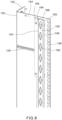
FIG. 8 is a front perspective view of the finger mounting bracket installed in the equipment rail ofFIG. 5 . -
FIG. 9 is a front perspective view of cable management fingers installed in the finger mounting bracket ofFIG. 8 . -
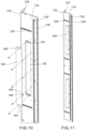
FIG. 10 is an exploded front perspective view of the rack unit covers and the equipment rail ofFIG. 5 . -
FIG. 11 is a front perspective view of the equipment rail ofFIG. 5 with the rack unit covers installed on the equipment rail. -
FIG. 5 illustrates adata center cabinet 100 withequipment rails 120. Thedata center cabinet 100 is defined by aframe 102 with two frontvertical posts 104, two backvertical posts 106, top side toside beams 108, bottom side toside beams 110, and a plurality of front toback beams 112. Theequipment rails 120 are installed at the front and back of thecabinet 100 and on each side of thecabinet 100. Theequipment rails 120 are L-shaped with afirst section 122 secured to the front toback beams 112 and asecond section 124. Thesecond section 124 includes a plurality ofopenings 126 extending the height of theequipment rail 120 for receiving the rack mounted equipment (not illustrated). - As illustrated in
FIG. 6 and FIG. 6A , theequipment rail 120 includes a plurality ofbeads equipment rail 120. The pressed inbeads 128 extend horizontally in thefirst section 122 and thesecond section 124 of theequipment rail 120. The pressed inbead 130 extends vertically the full height of theequipment rail 120 in thesecond section 124. - The pressed in
beads equipment rail 150 when subject to horizontal forces in the front to back direction. The pressed inbeads welded gussets 60 in the priorart equipment rails 50 as illustrated inFIGS. 1-4 . The pressed inbeads bead 130 also eliminates the need for thestiffening rib 62 that was welded to the priorart equipment rails 50 illustrated inFIGS. 1-4 . - As illustrated in
FIG. 7 , theequipment rail 120 includes a plurality ofvertical slots 132 andscrew hole openings 134. Afinger mounting bracket 150 is positioned to be mounted to theequipment rail 120. Thefinger mounting bracket 150 is designed to receivecable management fingers 170 for routing cables. Thefinger mounting bracket 150 includes afirst member 152 withsidewalls second member 162 parallel to thefirst member 152. Thesecond member 162 extends from a distal end of one of theside walls 154. A plurality ofhooks 158 extend from the distal end of theopposite side wall 156. Thefirst member 152 includes a plurality of diamond shapedopenings 160 for receivingcable management fingers 170, or other cable management accessory. Thesecond member 162 includes a plurality ofslots 164 for receiving fasteners to mount thefinger mounting bracket 150 to theequipment rail 120. - As illustrated in
FIG. 7 , thehooks 158 extending from thefinger mounting bracket 150 align with thevertical slots 132 in theequipment rail 120. Theslots 164 in thesecond member 162 align with thescrew hole openings 134 in theequipment rail 120. As illustrated inFIG. 8 , thehooks 158 extending from thefinger mount bracket 150 are installed through thevertical slots 132 and theslots 164 andholes 134 are aligned to receive a screw (not illustrated), or other fastener, to secure thefinger mounting bracket 150 to theequipment rail 120. The distal ends of theside walls first member 152 engage theequipment rail 120 forming anopen area 168 between thefirst member 150 and theequipment rail 120. As illustrated inFIG. 9 ,cable management fingers 170 are mounted in the diamond shapedopenings 160 with the mounting member on the back side of thecable management fingers 170 disposed within the diamond shapedopening 160 between thefinger mounting bracket 150 and theequipment rail 120. - The diamond shaped
openings 160 are blocked by theequipment rail 120 and the vertical bead pressed 130 into theequipment rail 120. - The
equipment rail 120 of the present disclosure no longer includes the diamond shapedopenings 54 for receiving the cable management fingers. As a result, removing the diamond shapedopenings 54 eliminates the need for thebulb seal 66 used to block air potentially bypassed through the diamond shapedopenings 54 in the prior art equipment rails 50 (seeFIG. 2A ). - As illustrated in
FIGS. 10 and 11 , theequipment rail 120 also includes an improvedrack unit cover 180.FIG. 10 illustrates the cover positioned to be installed on theequipment rail 120.FIG. 11 illustrates thecovers 180 of the present disclosure secured over the 1RU openings 136. It is common for equipment rails to include a vertical 1 RU (rack unit) opening 136 within theequipment rail 120. The 1RU openings 136 are designed for receiving pieces of equipment or patch panels that are compatible with the 1RU openings 136 per EIA/ECA-301-E standards. When the 1RU openings 136 are not in use, they are covered withmetal plates 180 to block air flow. As illustrated in the prior art cabinet ofFIG. 1 , thecovers 80 are only mounted to theequipment rail 50 at the top and bottom of theequipment rail 50. Thecovers 180 of the present disclosure includeside tabs 186 withfastener openings 188 in addition to thefastener openings cover 180. Theside tabs 186 withfastener openings 188 add rigidity to the 1RU openings 136 in theequipment rail 120 when thecover 180 is installed on theequipment rail 120. Thus, theadditional tabs 186 and fasteners provide additional structural support for the equipment rails 120 at the 1RU openings 136. - Furthermore, while the particular preferred embodiments of the present disclosure have been shown and described, it will be obvious to those skilled in the art that changes and modifications may be made without departing from the teaching of the disclosure. The matter set forth in the foregoing description and accompanying drawings is offered by way of illustration only and not as limitation. The actual scope of the invention is intended to be defined in the following claims when viewed in their proper perspective based on the prior art.
Claims (12)
- An equipment rail for mounting in a data center cabinet, the equipment rail comprising:a first section and a second section; anda finger mounting bracket secured to the second section, wherein the finger mounting bracket has a first member with sidewalls and a second member parallel to the first member, wherein distal ends of the sidewalls engage the equipment rail forming an open area between the first member and the equipment rail.
- The equipment rail of claim 1, wherein the second section of the equipment rail includes a plurality of openings extending a height of the equipment rail for receiving rack mounted equipment.
- The equipment rail of claim 1, wherein a plurality of beads are pressed into the equipment rail for adding rigidity to the equipment rails.
- The equipment rail of claim 3, wherein the plurality of beads include horizontal beads that extend in the first section and the second section.
- The equipment rail of claim 3, wherein the plurality of beads include a vertical bead extending a length of the equipment rail.
- The equipment rail of claim 1, wherein the second section includes a plurality of vertical slots and fastener openings.
- The equipment rail of claim 6, wherein the second member of the finger mounting bracket extends from a distal end of one of the sidewalls of the first member, a plurality of hooks extend from a distal end of opposite side wall of the first member, whereby the hooks are installed in the vertical slots in the equipment rail to secure the finger mounting bracket to the equipment rail.
- The equipment rail of claim 6, wherein the second member of the finger mounting brackets has a plurality of slots for receiving fasteners to mount the finger mounting bracket at the fastener openings in the equipment rail.
- The equipment rail of claim 1, the first member of the finger mounting bracket has a plurality of diamond openings for receiving a cable management accessory.
- The equipment rail of claim 1, further comprising rack unit openings adapted to receive equipment, and rack unit covers positioned to block the rack unit openings, wherein the rack unit covers have a plurality of side tabs with fastener openings.
- A data center cabinet comprising:a frame including front vertical posts, a first bottom side to side beam and a first top side to side beam positioned between and connected to the front vertical posts, back vertical posts, a second bottom side to side beam and a second top side to side beam positioned between and connected to the back vertical posts, a plurality of front to back beams positioned between and connected to one of the front vertical posts and one of the back vertical posts;equipment rails according to any preceding claim secured to the plurality of front to back beams.
- The data center cabinet of claim 11, wherein the equipment rails are positioned at a front and back of the cabinet on each side of the cabinet.
Applications Claiming Priority (1)
| Application Number | Priority Date | Filing Date | Title |
|---|---|---|---|
| US18/121,061 US20240314964A1 (en) | 2023-03-14 | 2023-03-14 | Equipment rail with finger mounting bracket |
Publications (3)
| Publication Number | Publication Date |
|---|---|
| EP4432793A2 true EP4432793A2 (en) | 2024-09-18 |
| EP4432793A3 EP4432793A3 (en) | 2024-09-25 |
| EP4432793B1 EP4432793B1 (en) | 2025-08-06 |
Family
ID=90097810
Family Applications (1)
| Application Number | Title | Priority Date | Filing Date |
|---|---|---|---|
| EP24159823.4A Active EP4432793B1 (en) | 2023-03-14 | 2024-02-27 | Equipment rail with finger mounting bracket |
Country Status (4)
| Country | Link |
|---|---|
| US (1) | US20240314964A1 (en) |
| EP (1) | EP4432793B1 (en) |
| JP (1) | JP2024132887A (en) |
| CN (1) | CN222148047U (en) |
Citations (1)
| Publication number | Priority date | Publication date | Assignee | Title |
|---|---|---|---|---|
| EP2392146B1 (en) * | 2009-01-27 | 2012-08-22 | Panduit Corp. | Vertical cable management system |
Family Cites Families (20)
| Publication number | Priority date | Publication date | Assignee | Title |
|---|---|---|---|---|
| DE19750427C1 (en) * | 1997-11-14 | 1999-07-08 | Loh Kg Rittal Werk | Fastening device |
| US5921402A (en) * | 1998-04-27 | 1999-07-13 | Systems Manufacturing Corporation | Cable management track system |
| WO2001001534A1 (en) * | 1999-06-28 | 2001-01-04 | Cooper B-Line Limited | Cable guiding |
| US6504100B2 (en) * | 2000-12-20 | 2003-01-07 | Chatsworth Products, Inc. | Flexible intra-cabinet cable ring wire management system |
| US7229050B2 (en) * | 2002-11-27 | 2007-06-12 | Hewlett-Packard Development Company, L.P. | Raceway system |
| US7188916B2 (en) * | 2004-03-29 | 2007-03-13 | Emc Corporation | Adjustable side rails and method of attaching same to mounting rails of cabinet racks |
| US7398949B2 (en) * | 2005-02-11 | 2008-07-15 | Dedicated Devices, Inc. | Electronic hardware mounting bracket |
| US20070210680A1 (en) * | 2006-03-13 | 2007-09-13 | Panduit Corp. | Network cabinet |
| US8221169B2 (en) * | 2009-09-15 | 2012-07-17 | Adc Telecommunications, Inc. | Fanning module, fanning strip, and cable management panel |
| US20120062091A1 (en) * | 2010-09-10 | 2012-03-15 | Donowho D Brian | Vertical mounting rail with cable management features |
| EP2429271A2 (en) * | 2010-09-10 | 2012-03-14 | Chatsworth Products, Inc. | Rail seal for electronic equipment enclosure |
| US8787023B2 (en) * | 2010-09-10 | 2014-07-22 | Chatsworth Products, Inc. | Rail mounting clamp for electronic equipment enclosure |
| US8901418B2 (en) * | 2012-06-25 | 2014-12-02 | Panduit Corp. | Server cabinet |
| CN103857238A (en) * | 2012-12-05 | 2014-06-11 | 鸿富锦精密工业(深圳)有限公司 | Equipment cabinet type server and wire arranging device thereof |
| US9581782B2 (en) * | 2014-08-28 | 2017-02-28 | Hubbell Incorporated | Cable management spool mounting assembly |
| CA2950839C (en) * | 2016-01-30 | 2023-09-12 | Cooper Technologies Company | Equipment rack and components thereof |
| US11598132B2 (en) * | 2019-04-09 | 2023-03-07 | Quanta Computer Inc. | Double shaft 180 degrees rotation sheet metal mechanism |
| US12035501B2 (en) * | 2020-05-04 | 2024-07-09 | Panduit Corp. | Data center cabinet |
| US11678451B2 (en) * | 2020-05-04 | 2023-06-13 | Panduit Corp. | Data center cabinet |
| US11622469B2 (en) * | 2020-05-04 | 2023-04-04 | Panduit Corp. | Data center cabinet and reusable transport casters for a data center cabinet |
-
2023
- 2023-03-14 US US18/121,061 patent/US20240314964A1/en active Pending
-
2024
- 2024-02-05 JP JP2024015600A patent/JP2024132887A/en active Pending
- 2024-02-27 EP EP24159823.4A patent/EP4432793B1/en active Active
- 2024-03-12 CN CN202420471285.6U patent/CN222148047U/en active Active
Patent Citations (1)
| Publication number | Priority date | Publication date | Assignee | Title |
|---|---|---|---|---|
| EP2392146B1 (en) * | 2009-01-27 | 2012-08-22 | Panduit Corp. | Vertical cable management system |
Also Published As
| Publication number | Publication date |
|---|---|
| EP4432793A3 (en) | 2024-09-25 |
| US20240314964A1 (en) | 2024-09-19 |
| EP4432793B1 (en) | 2025-08-06 |
| JP2024132887A (en) | 2024-10-01 |
| CN222148047U (en) | 2024-12-10 |
Similar Documents
| Publication | Publication Date | Title |
|---|---|---|
| US11792948B2 (en) | Cable pass-through panel for electronic equipment enclosure | |
| US10178784B2 (en) | Rail seal for electronic equipment enclosure | |
| US9943003B2 (en) | Electronics cabinet | |
| US6920273B2 (en) | High density fiber distribution frame | |
| US5930963A (en) | Wall panel system | |
| EP2429271A2 (en) | Rail seal for electronic equipment enclosure | |
| US4592602A (en) | Modular mounting rack system of vertical-type construction | |
| KR20060083865A (en) | Rack Systems, Adapters, Rack Frames, Support Rails, and Rack System Manufacturing Methods | |
| US8119915B2 (en) | Cable management patch panel system with vertical ducting | |
| EP1354535B1 (en) | Cabinet | |
| US7239523B1 (en) | Electronic assembly with modular midplane | |
| EP4432793B1 (en) | Equipment rail with finger mounting bracket | |
| CA2099544A1 (en) | Racks for electronic equipment | |
| US20020043508A1 (en) | Support bracket | |
| US5219443A (en) | Cabinet for accepting electronic assemblies | |
| EP3349554A1 (en) | Electronics cabinet | |
| CN213694501U (en) | Electrical equipment cabinet | |
| DE19947732A1 (en) | Wall-mountable bearer e.g. for switching cabinet, has adapter plates with standardized attachment plane with installation opening for attachment to attachment sections to at least partly cover frame openings | |
| JPH0750493A (en) | Mounting structure of drawer type housing | |
| CA2215847A1 (en) | Housing for rack mounted electronic equipment | |
| ZA200608653B (en) | Carrier of a distribution point in the field of telecommunications | |
| WO2000056133A1 (en) | Cabled installation mount for telecommunication apparatus |
Legal Events
| Date | Code | Title | Description |
|---|---|---|---|
| PUAI | Public reference made under article 153(3) epc to a published international application that has entered the european phase |
Free format text: ORIGINAL CODE: 0009012 |
|
| STAA | Information on the status of an ep patent application or granted ep patent |
Free format text: STATUS: THE APPLICATION HAS BEEN PUBLISHED |
|
| PUAL | Search report despatched |
Free format text: ORIGINAL CODE: 0009013 |
|
| AK | Designated contracting states |
Kind code of ref document: A2 Designated state(s): AL AT BE BG CH CY CZ DE DK EE ES FI FR GB GR HR HU IE IS IT LI LT LU LV MC ME MK MT NL NO PL PT RO RS SE SI SK SM TR |
|
| AK | Designated contracting states |
Kind code of ref document: A3 Designated state(s): AL AT BE BG CH CY CZ DE DK EE ES FI FR GB GR HR HU IE IS IT LI LT LU LV MC ME MK MT NL NO PL PT RO RS SE SI SK SM TR |
|
| RIC1 | Information provided on ipc code assigned before grant |
Ipc: H04Q 1/06 20060101ALI20240822BHEP Ipc: H05K 7/18 20060101ALI20240822BHEP Ipc: H05K 7/14 20060101AFI20240822BHEP |
|
| STAA | Information on the status of an ep patent application or granted ep patent |
Free format text: STATUS: REQUEST FOR EXAMINATION WAS MADE |
|
| 17P | Request for examination filed |
Effective date: 20250225 |
|
| GRAP | Despatch of communication of intention to grant a patent |
Free format text: ORIGINAL CODE: EPIDOSNIGR1 |
|
| STAA | Information on the status of an ep patent application or granted ep patent |
Free format text: STATUS: GRANT OF PATENT IS INTENDED |
|
| INTG | Intention to grant announced |
Effective date: 20250423 |
|
| GRAS | Grant fee paid |
Free format text: ORIGINAL CODE: EPIDOSNIGR3 |
|
| GRAA | (expected) grant |
Free format text: ORIGINAL CODE: 0009210 |
|
| STAA | Information on the status of an ep patent application or granted ep patent |
Free format text: STATUS: THE PATENT HAS BEEN GRANTED |
|
| AK | Designated contracting states |
Kind code of ref document: B1 Designated state(s): AL AT BE BG CH CY CZ DE DK EE ES FI FR GB GR HR HU IE IS IT LI LT LU LV MC ME MK MT NL NO PL PT RO RS SE SI SK SM TR |
|
| REG | Reference to a national code |
Ref country code: GB Ref legal event code: FG4D |
|
| REG | Reference to a national code |
Ref country code: CH Ref legal event code: EP |
|
| REG | Reference to a national code |
Ref country code: IE Ref legal event code: FG4D |
|
| REG | Reference to a national code |
Ref country code: DE Ref legal event code: R096 Ref document number: 602024000387 Country of ref document: DE |
|
| REG | Reference to a national code |
Ref country code: NL Ref legal event code: MP Effective date: 20250806 |
|
| PG25 | Lapsed in a contracting state [announced via postgrant information from national office to epo] |
Ref country code: IS Free format text: LAPSE BECAUSE OF FAILURE TO SUBMIT A TRANSLATION OF THE DESCRIPTION OR TO PAY THE FEE WITHIN THE PRESCRIBED TIME-LIMIT Effective date: 20251206 |
|
| PG25 | Lapsed in a contracting state [announced via postgrant information from national office to epo] |
Ref country code: NO Free format text: LAPSE BECAUSE OF FAILURE TO SUBMIT A TRANSLATION OF THE DESCRIPTION OR TO PAY THE FEE WITHIN THE PRESCRIBED TIME-LIMIT Effective date: 20251106 |
|
| REG | Reference to a national code |
Ref country code: LT Ref legal event code: MG9D |
|
| PG25 | Lapsed in a contracting state [announced via postgrant information from national office to epo] |
Ref country code: PT Free format text: LAPSE BECAUSE OF FAILURE TO SUBMIT A TRANSLATION OF THE DESCRIPTION OR TO PAY THE FEE WITHIN THE PRESCRIBED TIME-LIMIT Effective date: 20251209 |
|
| PG25 | Lapsed in a contracting state [announced via postgrant information from national office to epo] |
Ref country code: FI Free format text: LAPSE BECAUSE OF FAILURE TO SUBMIT A TRANSLATION OF THE DESCRIPTION OR TO PAY THE FEE WITHIN THE PRESCRIBED TIME-LIMIT Effective date: 20250806 |
|
| PG25 | Lapsed in a contracting state [announced via postgrant information from national office to epo] |
Ref country code: HR Free format text: LAPSE BECAUSE OF FAILURE TO SUBMIT A TRANSLATION OF THE DESCRIPTION OR TO PAY THE FEE WITHIN THE PRESCRIBED TIME-LIMIT Effective date: 20250806 Ref country code: NL Free format text: LAPSE BECAUSE OF FAILURE TO SUBMIT A TRANSLATION OF THE DESCRIPTION OR TO PAY THE FEE WITHIN THE PRESCRIBED TIME-LIMIT Effective date: 20250806 |
|
| PG25 | Lapsed in a contracting state [announced via postgrant information from national office to epo] |
Ref country code: GR Free format text: LAPSE BECAUSE OF FAILURE TO SUBMIT A TRANSLATION OF THE DESCRIPTION OR TO PAY THE FEE WITHIN THE PRESCRIBED TIME-LIMIT Effective date: 20251107 |
|
| PG25 | Lapsed in a contracting state [announced via postgrant information from national office to epo] |
Ref country code: SE Free format text: LAPSE BECAUSE OF FAILURE TO SUBMIT A TRANSLATION OF THE DESCRIPTION OR TO PAY THE FEE WITHIN THE PRESCRIBED TIME-LIMIT Effective date: 20250806 |
|
| PG25 | Lapsed in a contracting state [announced via postgrant information from national office to epo] |
Ref country code: LV Free format text: LAPSE BECAUSE OF FAILURE TO SUBMIT A TRANSLATION OF THE DESCRIPTION OR TO PAY THE FEE WITHIN THE PRESCRIBED TIME-LIMIT Effective date: 20250806 |
|
| PG25 | Lapsed in a contracting state [announced via postgrant information from national office to epo] |
Ref country code: BG Free format text: LAPSE BECAUSE OF FAILURE TO SUBMIT A TRANSLATION OF THE DESCRIPTION OR TO PAY THE FEE WITHIN THE PRESCRIBED TIME-LIMIT Effective date: 20250806 Ref country code: PL Free format text: LAPSE BECAUSE OF FAILURE TO SUBMIT A TRANSLATION OF THE DESCRIPTION OR TO PAY THE FEE WITHIN THE PRESCRIBED TIME-LIMIT Effective date: 20250806 |
|
| PG25 | Lapsed in a contracting state [announced via postgrant information from national office to epo] |
Ref country code: RS Free format text: LAPSE BECAUSE OF FAILURE TO SUBMIT A TRANSLATION OF THE DESCRIPTION OR TO PAY THE FEE WITHIN THE PRESCRIBED TIME-LIMIT Effective date: 20251106 |
|
| PG25 | Lapsed in a contracting state [announced via postgrant information from national office to epo] |
Ref country code: ES Free format text: LAPSE BECAUSE OF FAILURE TO SUBMIT A TRANSLATION OF THE DESCRIPTION OR TO PAY THE FEE WITHIN THE PRESCRIBED TIME-LIMIT Effective date: 20250806 |
|
| REG | Reference to a national code |
Ref country code: AT Ref legal event code: MK05 Ref document number: 1823536 Country of ref document: AT Kind code of ref document: T Effective date: 20250806 |
|
| PG25 | Lapsed in a contracting state [announced via postgrant information from national office to epo] |
Ref country code: SM Free format text: LAPSE BECAUSE OF FAILURE TO SUBMIT A TRANSLATION OF THE DESCRIPTION OR TO PAY THE FEE WITHIN THE PRESCRIBED TIME-LIMIT Effective date: 20250806 |
|
| PG25 | Lapsed in a contracting state [announced via postgrant information from national office to epo] |
Ref country code: DK Free format text: LAPSE BECAUSE OF FAILURE TO SUBMIT A TRANSLATION OF THE DESCRIPTION OR TO PAY THE FEE WITHIN THE PRESCRIBED TIME-LIMIT Effective date: 20250806 |
|
| PGFP | Annual fee paid to national office [announced via postgrant information from national office to epo] |
Ref country code: DE Payment date: 20260227 Year of fee payment: 3 |
|
| PG25 | Lapsed in a contracting state [announced via postgrant information from national office to epo] |
Ref country code: AT Free format text: LAPSE BECAUSE OF FAILURE TO SUBMIT A TRANSLATION OF THE DESCRIPTION OR TO PAY THE FEE WITHIN THE PRESCRIBED TIME-LIMIT Effective date: 20250806 |
|
| PG25 | Lapsed in a contracting state [announced via postgrant information from national office to epo] |
Ref country code: IT Free format text: LAPSE BECAUSE OF FAILURE TO SUBMIT A TRANSLATION OF THE DESCRIPTION OR TO PAY THE FEE WITHIN THE PRESCRIBED TIME-LIMIT Effective date: 20250806 |
|
| PGFP | Annual fee paid to national office [announced via postgrant information from national office to epo] |
Ref country code: FR Payment date: 20260225 Year of fee payment: 3 |
|
| PG25 | Lapsed in a contracting state [announced via postgrant information from national office to epo] |
Ref country code: CZ Free format text: LAPSE BECAUSE OF FAILURE TO SUBMIT A TRANSLATION OF THE DESCRIPTION OR TO PAY THE FEE WITHIN THE PRESCRIBED TIME-LIMIT Effective date: 20250806 |
|
| PG25 | Lapsed in a contracting state [announced via postgrant information from national office to epo] |
Ref country code: EE Free format text: LAPSE BECAUSE OF FAILURE TO SUBMIT A TRANSLATION OF THE DESCRIPTION OR TO PAY THE FEE WITHIN THE PRESCRIBED TIME-LIMIT Effective date: 20250806 Ref country code: SK Free format text: LAPSE BECAUSE OF FAILURE TO SUBMIT A TRANSLATION OF THE DESCRIPTION OR TO PAY THE FEE WITHIN THE PRESCRIBED TIME-LIMIT Effective date: 20250806 |