EP4432687A1 - Imaging device and equipment - Google Patents
Imaging device and equipment Download PDFInfo
- Publication number
- EP4432687A1 EP4432687A1 EP24162536.7A EP24162536A EP4432687A1 EP 4432687 A1 EP4432687 A1 EP 4432687A1 EP 24162536 A EP24162536 A EP 24162536A EP 4432687 A1 EP4432687 A1 EP 4432687A1
- Authority
- EP
- European Patent Office
- Prior art keywords
- region
- event
- imaging device
- predicted
- output
- Prior art date
- Legal status (The legal status is an assumption and is not a legal conclusion. Google has not performed a legal analysis and makes no representation as to the accuracy of the status listed.)
- Pending
Links
Images




Classifications
-
- G—PHYSICS
- G06—COMPUTING OR CALCULATING; COUNTING
- G06V—IMAGE OR VIDEO RECOGNITION OR UNDERSTANDING
- G06V20/00—Scenes; Scene-specific elements
- G06V20/40—Scenes; Scene-specific elements in video content
- G06V20/44—Event detection
-
- H—ELECTRICITY
- H04—ELECTRIC COMMUNICATION TECHNIQUE
- H04N—PICTORIAL COMMUNICATION, e.g. TELEVISION
- H04N25/00—Circuitry of solid-state image sensors [SSIS]; Control thereof
- H04N25/70—SSIS architectures; Circuits associated therewith
- H04N25/703—SSIS architectures incorporating pixels for producing signals other than image signals
- H04N25/707—Pixels for event detection
-
- G—PHYSICS
- G06—COMPUTING OR CALCULATING; COUNTING
- G06T—IMAGE DATA PROCESSING OR GENERATION, IN GENERAL
- G06T7/00—Image analysis
- G06T7/20—Analysis of motion
-
- G—PHYSICS
- G06—COMPUTING OR CALCULATING; COUNTING
- G06V—IMAGE OR VIDEO RECOGNITION OR UNDERSTANDING
- G06V10/00—Arrangements for image or video recognition or understanding
- G06V10/40—Extraction of image or video features
- G06V10/60—Extraction of image or video features relating to illumination properties, e.g. using a reflectance or lighting model
-
- H—ELECTRICITY
- H04—ELECTRIC COMMUNICATION TECHNIQUE
- H04N—PICTORIAL COMMUNICATION, e.g. TELEVISION
- H04N25/00—Circuitry of solid-state image sensors [SSIS]; Control thereof
- H04N25/47—Image sensors with pixel address output; Event-driven image sensors; Selection of pixels to be read out based on image data
-
- H—ELECTRICITY
- H04—ELECTRIC COMMUNICATION TECHNIQUE
- H04N—PICTORIAL COMMUNICATION, e.g. TELEVISION
- H04N25/00—Circuitry of solid-state image sensors [SSIS]; Control thereof
- H04N25/70—SSIS architectures; Circuits associated therewith
- H04N25/76—Addressed sensors, e.g. MOS or CMOS sensors
- H04N25/78—Readout circuits for addressed sensors, e.g. output amplifiers or A/D converters
Definitions
- the technology of the present disclosure relates to an event-based imaging device and an equipment.
- an event-based sensor With the recent proliferation of the Internet of Things (IoT), artificial intelligence (AI), autonomous driving, and the like, an event-based sensor has been proposed as an image sensor that consumes less power and operates faster than a conventional sensor.
- An event-based sensor is also called a dynamic vision sensor.
- This sensor monitors changes in the light intensity of each pixel in a two-dimensional pixel array, and detects changes as events.
- An event-based sensors can detect and output an event at a timing when the light intensity changes, irrespective of object detection processing or image processing, thereby achieving low power consumption and high speed operation.
- Japanese Patent Application Publication No. 2020-136958 proposes an event-based sensor that sets event detection probability, based on a result of object detection using pixel value pattern recognition.
- the temporal resolution of the object detection processing is lower than the temporal resolution of the output data of the event-based sensor.
- a delay in the object detection processing may also cause a delay in reading out the event signals.
- the object of the detection target may move out of the specific region that is set, whereby an event of the object located outside this specific region may not be read out.
- the event-based sensor described above may fail to accurately detect as an event a change in the subject in the pixel array.
- the technology of the present disclosure allows an event-based imaging device to perform event detection on a moving subject with improved accuracy.
- an imaging device as specified in claims 1 to 19.
- an event-based imaging device is mainly described as an example of a photoelectric conversion device.
- the embodiments are not limited to event-based imaging devices, and can be applied to other examples of photoelectric conversion devices.
- the embodiments are applicable to distance measuring devices (devices for distance measurement using focus detection and Time of Flight (TOF)), photometry devices (devices for measuring the amount of incident light), and the like.
- TOF Time of Flight
- FIG. 1 shows a schematic configuration of an event-based imaging device 100 according to a first embodiment.
- the event-based imaging device 100 includes a pixel portion 101, an event readout portion 103, a memory 105, an ROI (Region Of Interest) determination portion 106, a motion prediction portion 107, a predicted region determination portion 108, and an event rate control portion 109.
- ROI Region Of Interest
- the pixel portion 101 includes a plurality of unit pixels 110 arranged in a two-dimensional array as with a general image sensor, for example.
- the unit pixels 110 may be arranged in the same manner as a one-dimensional line sensor or in another arrangement.
- Each unit pixel 110 is a pixel that can detect a change in the intensity of incident light as an event signal, and includes a circuit illustrated in FIG. 2 .
- one unit pixel 110 includes a photodiode 200, a logarithmic I/V conversion portion 201, a subtraction portion 202, and a comparison portion 203.
- the photodiode 200 In the unit pixel 110, the photodiode 200 generates a photocurrent I p according to the intensity of incident light.
- the logarithmic I/V conversion portion 201 converts the photocurrent I P into a potential, and obtains the logarithmic potential Vi by conversion using a logarithmic function.
- the output V 1 of the logarithmic I/V conversion portion 201 does not necessarily have to be a logarithmic potential, and may be a potential that changes linearly with the intensity of incident light, or any other value that changes with the light intensity.
- the subtraction portion 202 calculates the difference V d between the logarithmic potential Vi and the reference potential.
- the comparison portion 203 compares the difference V d calculated by the subtraction portion with a predetermined threshold.
- the comparison portion 203 uses two thresholds, a positive threshold T1 and a negative threshold T2. When the difference V d becomes higher than the positive threshold or lower than the negative threshold, an event signal with a value different from a value of 0 is generated and detected as an event.
- An event signal E of a pixel P (x, y) at time t can be expressed by the following formula (1).
- E x ,y ,t ⁇ 1 v d > T 1 ⁇ 1 v d ⁇ T 2 0 other than above
- the temporal resolution of event detection of the unit pixel 110 at time t may be 1 ⁇ s, for example.
- the event signal E has a value of 1, it indicates that a change has occurred in which the unit pixel 110 has become brighter, that is, the occurrence of a positive event.
- the event signal E has a value of -1, it indicates that a change has occurred in which the unit pixel 110 has become darker, that is, the occurrence of a negative event.
- Formula (1) above is merely an example of the expression of the event signal E. It is also possible to assign different numerical values to a positive event, a negative event, or a state without any event, to handle a positive event and a negative as one type of event signal without distinguishing them, or to use other expressions.
- An event signal E is generated independently of (asynchronously with) a frame synchronization signal used in a general image sensor. The use of an event signal E enables events to be detected with high temporal resolution.
- a detected event signal E is sent to the event readout portion 103.
- the reference potential is updated using a response signal Ack from the event readout portion 103, which will be described below, as a trigger.
- the pixel portion 101 is configured to output an event signal transmission request signal Req to the event readout portion 103 on a row-by-row basis.
- a transmission request signal Req is output from each pixel row 102 when at least one of the unit pixels 110 of the columns of the pixel row 102 detects an event signal, that is, when the value of the event signal E becomes 1 or -1.
- a transmission request is output from the pixel portion 101 on a row-by-row basis.
- the pixel groups may be configured in the units of columns, rectangular regions having a fixed width in the row or column direction, or any other units, and each unit may send a transmission request.
- the event readout portion 103 reads out event signals from the pixel portion 101.
- the event readout portion 103 includes an arbitration portion 600, which arbitrates transmission request signals Req from the pixel rows 102 of the pixel portion 101, for example. Details of the arbitration portion 600 will be described below with reference to FIG. 6 .
- the arbitration portion 600 reads out the event signals E of the pixels in the selected pixel row 102. When the event signals E are read out by the arbitration portion 600, the value of the event signal E of each unit pixel 110 in the pixel row 102 is returned to zero.
- the event readout portion 103 sends back a response signal Ack to the pixel row 102, and each unit pixel 110 of the pixel row 102 restarts event detection using, as the new reference potential, the logarithmic potential V 1 at the time of receiving the response signal Ack.
- the event signals of the pixel portion 101 read by the event readout portion 103 are used as an input for controlling an event rate as an event readout frequency, which will be described below, and are also used to generate final output data of the event-based imaging device 100.
- the event readout portion 103 can add the coordinate values and time stamps to the event signal. To add the coordinate values, the position of the row and column directions of the event signal read by the event readout portion 103 are determined. Also, the event readout portion 103 may include a timer circuit (not shown) and add the output value of the timer at the event readout time to the event signal as a time stamp. The event readout portion 103 generates and outputs event data in this manner.
- a bus 104 is used for data transfer between the event readout portion 103 and the memory 105, the ROI determination portion 106, the motion prediction portion 107, the predicted region determination portion 108, and the event rate control portion 109, which will be described below.
- the memory 105 temporarily stores intermediate data of processing, such as event data output from the event readout portion 103 and input/output data of the ROI determination portion 106, the motion prediction portion 107, the predicted region determination portion 108, and the event rate control portion 109, which will be described below.
- the ROI determination portion 106 performs processing for detecting an region of interest from the read event data, such as detecting whether a target of interest (TOI) is present.
- a region of interest detected by the ROI determination portion 106 is referred to as a "preliminary region of interest”.
- This processing may be object detection processing using a convolutional neural network (CNN), for example.
- CNN convolutional neural network
- the ROI determination portion 106 performs preliminary region of interest detection processing at regular time intervals in accordance with the time required for object detection processing, for example.
- a CNN requires input data in an array structure, such as frame image data output from a general image sensor as input data.
- data obtained by converting the output event sequence from the event readout portion 103 into an array structure may be stored in the memory 105, and the ROI determination portion 106 may be configured to read the stored data from the memory 105 and process it.
- event sequence array structure representation is the two-dimensional histogram format, which uses the number of events that occurred in the pixel during a specific period as the value corresponding to the pixel value of output image data of a general image sensor.
- the Time Surface format may also be used in which the latest time stamp of the events that occurred in each pixel is used as the value corresponding to the pixel value of output image data of a general image sensor.
- the ROI determination portion 106 may output region information of the detected preliminary region of interest and the event rate of the corresponding region, for example. Multiple regions may be detected as preliminary regions of interest.
- FIG. 3 is a diagram illustrating an example of a region of interest detected by the above processing.
- a vehicle 301 traveling on a road surface 300 is imaged by the event-based imaging device 100.
- a preliminary region of interest 302 is a region of interest determined by the ROI determination portion 106 detecting the vehicle 301 as a target of interest (TOI).
- the region information of the preliminary region of interest 302 may be expressed as a set of values of the upper left coordinates and the lower right coordinates of the preliminary region of interest 302, provided that this region is a rectangular region in the pixel portion 101.
- the event rate of the events used to determine the preliminary region of interest 302 may be assigned according to the type of the TOI (e.g., person, vehicle, traffic light), and may be a value between 0 and 1, for example.
- the region of interest determination portion 106 determines the preliminary region of interest 302 by repeatedly performing processing every fixed period of time, for example, every 10 ms.
- the time cycle (for example, 10 ms) for updating the preliminary region of interest 302 is generally greater than the temporal resolution for event detection (for example, 1 ⁇ s), but this will not be limitations in achieving the processing of the present embodiment.
- the motion prediction portion 107 is an output portion that outputs motion information regarding the motion of each of the preliminary regions of interest output by the ROI determination portion 106.
- the motion information may include information indicating the type of motion of the event-based imaging device 100, such as two-dimensional translation (x-axis direction (horizontal direction) and y-axis direction (vertical direction)), rotation, yaw, pitch, and zoom. Additionally or alternatively, the motion information may include information indicating the type of motion of the TOI imaged by the event-based imaging device 100, such as two-dimensional translation (x-axis direction (horizontal direction) and y-axis direction (vertical direction)), rotation, yaw, pitch, and zoom. Additionally or alternatively, the motion information may include information indicating the amount of motion, such as the speed or acceleration of the target.
- the predicted region determination portion 108 determines a predicted region that will be present after the preliminary region of interest has changed between the current time and a future time.
- the predicted region determination portion 108 outputs the region information of the determined predicted region.
- the time of the time point of FIG. 3 is defined as a current time t
- the time of the time point at which a preliminary region of interest is calculated immediately before the time point of FIG. 3 (time t) is defined as a past time t-1.
- the time of the time point at which a preliminary region of interest is calculated immediately after the time point of FIG. 3 (time t) is defined as a future time t+1.
- FIG. 4A shows an example of a vehicle 401 and a preliminary region of interest 402 at time t-1.
- the vehicle 401 imaged by the event-based imaging device 100 and the preliminary region of interest 402 determined by the ROI determination portion 106 are each shown as rectangular regions.
- FIG. 4B shows an example of a vehicle 411 and a predicted region 412 at time t+1 predicted by the predicted region determination portion 108 based on the motion information output by the motion prediction portion 107.
- the vehicle 401 imaged by the event-based imaging device 100 and the preliminary region of interest 402 determined by the ROI determination portion 106 are each shown as rectangular regions indicated by broken lines.
- the preliminary region of interest 402 determined by the ROI determination portion 106, which is a first region determination portion, at time t-1 is an example of a first region.
- the motion prediction portion 107 calculates an optical flow using the region information of the preliminary region of interest 402 at time t-1 and the events detected by the event-based imaging device 100 between time t-1 and time t.
- the optical flow is vector information that represents changes in each pixel or each region of interest, and is calculated based on changes in the positions of events that occur within a specific period in a specific region.
- the motion prediction portion 107 calculates the type and/or amount of motion of the preliminary region of interest 402 from the optical flow.
- the motion prediction portion 107 calculates the region information of the predicted region 412 at future time t+1 by interpolating changes in the preliminary region of interest 402 up to time t+1 using the optical flow.
- the predicted region 412 at time t+1 is an example of a predicted region at time t+1 after a change in the first region determined by the predicted region determination portion 108, which is the second region determination portion.
- the method for calculating the optical flow from the event signals detected by the pixel portion 101 and the method for calculating the type and amount of motion of the preliminary region of interest from the optical flow may be achieved using known algorithms.
- the methods described herein are merely examples, and any other methods may be used to obtain the type and amount of motion of the region of interest based on the event signals detected by the pixel portion and the event data generated by the event readout portion.
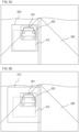
- FIG. 5A shows an example of a predicted region determined by the predicted region determination portion 108 in the example shown in FIGS. 3 , 4A and 4B .
- the predicted region 412 shown in FIG. 4B is shown in the image shown in FIG. 3 .
- the predicted region determination portion 108 outputs the region information of the smallest rectangular region including the preliminary region of interest 302 at the current time t and the predicted region 412 at the future time t+1 as the region information of the predicted region after a change in the region of interest.
- FIG. 5A also shows this predicted region 502.
- the predicted region determination portion 108 may calculate the confidence of the motion prediction of the preliminary region of interest by the motion prediction portion 107, for example.
- the predicted region determination portion 108 may use, instead of the predicted region 502, a predicted region 512 obtained by adding margins to the top, bottom, left, and right of the predicted region 502 in FIG. 5A , as shown in FIG. 5B .
- the value of confidence of motion prediction may be set to be higher when the difference between the predicted region at the current time, which is predicted based on the past preliminary region of interest and motion information, and the preliminary region of interest at the current time is smaller.
- Examples of the difference between the predicted region and the preliminary region of interest include a difference in coordinates of the regions, a difference in width of the regions in the x-axis direction, and a difference in width of the regions in the y-axis direction.
- the event rate control portion 109 controls the event rate, which is the frequency at which the event readout portion 103 reads out events in the predicted region, based on the region information of each predicted region.
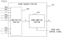
- FIG. 6 shows an example of the configuration of the event readout portion 103.
- the arbitration portion 600 arbitrates transmission request signals Req output for the respective rows of the pixel portion 101. More specifically, in the order of reception of transmission request signals Req, the arbitration portion 600 repeatedly reads the events of the corresponding row, returns a response signal Ack, and outputs the read events to the subsequent step, for example.
- the arbitration processing by the arbitration portion 600 described above is not limited to this, and the arbitration portion 600 may sequentially check for a transmission request from the top row of the pixel portion 101 and sequentially read out the rows with transmission requests.
- a down-sampling portion 601 down-samples the event signals E output from the arbitration portion 600 in a spatial direction (for example, row direction or column direction) or a temporal direction, and output the signals.
- event rate setting values are merely examples, and may be set freely corresponding to the type of subject of the region of interest.
- the event rate control portion 109 controls the down-sampling portion 601 so as not to down-sample the event signals of that region output from the arbitration portion 600.
- the event rate control portion 109 controls the down-sampling portion 601 so as to output 20% of the event signals of that region output from the arbitration portion 600.
- the down-sampling portion 601 down-samples the event signals of rows and columns and time stamps using a fixed pattern.
- the down-sampling portion 601 may perform down-sampling using a random pattern that probabilistically determines whether to down-sample relevant rows, columns, and time stamps.
- intermediate data of processing by each processing portion is temporarily held in the memory 105, but this is not an essential configuration for implementing this embodiment. It may be configured that the data from processing portions is exchanged directly between processing portions without being held by the memory 105.
- a spiking neural network SNN
- the event data output by the event readout portion 103 may be directly input in chronological order to the ROI determination portion 106 for performing object detection using the SNN.
- the motion prediction portion 107, the predicted region determination portion 108, and the event rate control portion 109 can also perform the above processing by processing inputs in chronological order without using the memory 105.
- the region of interest determination portion 106, the motion prediction portion 107, the predicted region determination portion 108, and the event rate control portion 109 are arranged within the event-based imaging device 100.
- these processing portions may be placed outside the event-based imaging device 100.
- event data is transmitted from the event-based imaging device 100 to an information processing device (not shown) via an external interface, and the information processing device that has received the event data performs the above-mentioned predicted region determination processing.
- the event rate control signal is fed back to the event-based imaging device 100 to perform the event rate control according to the present invention.
- the placement of any of the processing portions outside the event-based imaging device 100 may be determined as appropriate.
- the event-based imaging device 100 With an event-based imaging device of conventional art, when an event signal is generated, the event detection circuit of each pixel issues a signal requesting the arbitration portion to read out the event signal, and the arbitration portion selects the row to be read out. However, since the event signal is read out row by row, when transmission request signals are issued from two or more rows, there will be pixels that have to wait for their event signals to be read by the arbitration portion. In particular, when the event-based imaging device is mounted on a movable member, events can be detected from all positions within the field of view of the event-based imaging device.
- a pixel may have to wait for a time corresponding to 720 ⁇ H at maximum.
- H is the time required to read out events of one row of the pixel portion.
- a standby time delay time
- the temporal resolution of the time stamp added to the event signal is high, such as 1 ⁇ s
- the amount of time required to wait for readout causes an error of the time stamp.
- the temporal resolution of the time stamp is equivalent to 1 ms
- the low latency performance of the event-based imaging device corresponding to the frame rate in a general image sensor
- artifacts due to time stamp errors may occur (for example, what is actually a straight line may be observed as a curved line). Artifacts may reduce the recognition accuracy of the TOI of the event-based imaging device, for example.
- the previous event signal may be lost.
- the event-based imaging device 100 of this embodiment can determine the predicted region based on the motions of the event-based imaging device 100 and the TOI, and continuously capture the TOI within the predicted region. As such, the event detection is reduced for the region of the pixel portion not relating to the TOI, allowing the event detection for the region relating to the TOI to be performed with a higher temporal resolution. Accordingly, the event-based imaging device 100 of this embodiment can reduce the occurrence of time stamp errors and loss of event signals, which are concerns in event-based imaging devices of conventional art. Furthermore, with the event-based imaging device 100 of this embodiment, the reduction in the event detection for the region not relating to the TOI reduces the amount of information. This is expected to provide the effect of reducing power consumption associated with signal transmission.
- FIG. 7 shows an example of the configuration of the event readout portion 103 of the event-based imaging device 100 according to the present embodiment. As shown in FIG. 7 , in the event readout portion 103 of this embodiment, an event rate control signal is input to the arbitration portion 600 and the down-sampling portion 601.
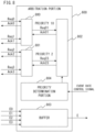
- FIG. 8 shows an example of the configuration of the arbitration portion 600 of this embodiment.
- the arbitration portion 600 has a four-input one-output configuration, and outputs the event signal of one selected row while controlling the order of readout of four rows of the pixel portion 101.
- the transmission request signals of four rows are Req0, Req1, Req2, and Req3.
- the response signals corresponding to the respective transmission request signals are Ack0, Ack1, Ack2, and Ack3.
- the event signals corresponding to the respective transmission request signals are E0, E1, E2, and E3.
- An arbitration circuit 800 has a two-input one-output configuration. When transmission request signals Req0 and Req1 are input simultaneously, the arbitration circuit 800 selects one of the transmission request signals and outputs the selected transmission request signal (indicated by Req01 in the figure) to the subsequent step. Likewise, an arbitration circuit 801 selects one of transmission request signals Req2 and Req3 and outputs the selected transmission request signal (indicated by Req23 in the figure) to the subsequent step.
- Transmission request signals Req01 and Req23 from the arbitration circuits 800 and 801, respectively, are input to an arbitration circuit 802, which outputs corresponding response signals Ack01, Ack23 to the arbitration circuits 800, 801.
- the arbitration circuit 802 selects one of transmission request signals Req01 and Req23, and returns response signal Ack01 or Ack23 corresponding to the selected transmission request signal.
- the arbitration circuit 800 that has received Ack01, or the arbitration circuit 801 that has received Ack23 sends one of response signals Ack0, Ack1, Ack2, and Ack3 corresponding to the transmission request signal selected when outputting transmission request signal Req01 or Req23 to the pixel portion 101.
- the arbitration circuit 800 selects transmission request signal Req1 and outputs transmission request signal Req01 to the subsequent step, it outputs response signal Ack1 corresponding to transmission request signal Req1 to the pixel portion 101.
- the response signal is sent back in the reverse direction of the transmission request signal relayed from the arbitration circuit of the previous step, and the row to be read out is determined. Then, the event signals of the pixels of the single row that has received the response signal are stored in a buffer 803.
- the buffer 803 sequentially outputs the event signal of one row to the subsequent step.
- the arbitration circuits 800, 801, and 802 arbitrate transmission request signals by selecting transmission request signals according to the ratio of priority values.
- the arbitration circuit 800 performs arbitration such that Req0 and Req1 are output to the subsequent arbitration circuit 802 with the same frequency.
- event signals E0 and E1 of the upper two rows of the pixel portion 101 are output from the buffer 803 of the arbitration portion 600 more frequently than event signals E2 and E3 of the lower two rows of the pixel portion 101.
- the down-sampling portion 601 performs the same down-sampling as in the first embodiment in the column direction and the temporal direction.
- the number of rows of the pixel portion 101 input to the arbitration portion 600 is four, but the number of rows may be any number.
- the arbitration circuits forming the arbitration portion 600 have a two-step configuration consisting of the first-step arbitration circuits 800 and 801 and the second-step arbitration circuit 802, but the number of steps of the arbitration circuits may be changed according to the number of rows of transmission request signals input from the pixel portion 101.
- the arbitration circuits may also be configured such that transmission request signals of three or more rows are input to one arbitration circuit.
- the priority determination portion 804 sets the priority only for the arbitration circuit 802. Additionally or alternatively, the priority determination portion 804 may be configured to set the priority for the arbitration circuit 800 and/or the arbitration circuit 801.
- the present embodiment assumes that transmission request signals Req0, Req1, Req2, and Req3 are input to the arbitration portion 600 in units of rows of the pixel portion 101. However, it may be configured that transmission request signals are input to the arbitration portion 600 in units of columns, units of rectangular regions having a fixed width in the row direction and a fixed width in the column direction, as well as pixel groups of any units of the pixel portion 101.
- the event readout portion 103 of this embodiment may be configured so as not to have the down-sampling portion 601.
- the arbitration portion 600 performs the above event rate control in accordance with the event rate control signal.
- the arbitration portion 600 can control the readout frequency of event signals detected by the pixel portion 101 for each pixel group (e.g., row units, column units, or rectangular region units) of the pixel portion 101.
- the down-sampling portion 601 down-samples event signals, so that some of the event signals input to the event readout portion 103 are discarded and not output to the subsequent step.
- the event signals that are not output from the event readout portion 103 to the subsequent step are controlled so as not to be input to the event readout portion 103 through arbitration by the arbitration portion 600.
- the event-based imaging device 100 of the present embodiment can further reduce processing delays caused by event signal readout.
- the configuration of an event-based imaging device 100 of the present embodiment is similar to the event-based imaging device 100 of the first embodiment shown in FIG. 1 .
- the processing of the event rate control portion 109 differs from the processing of the event rate control portion 109 in the first embodiment. Referring to FIG. 5A , the processing of the event rate control portion 109 in the present embodiment is now described.
- the event rate control portion 109 controls the event rate according to the area ratio between the preliminary region of interest 302 calculated by the ROI determination portion 106 and the predicted region 502 calculated by the predicted region determination portion 108.
- the first event rate corresponding to the preliminary region of interest 302 is I 1
- the second event rate corresponding to the predicted region 502 is I 2
- the area of the preliminary region of interest 302 is S 1
- the area of the predicted region 502 is S 2
- Event rate I 1 is an example of the first readout frequency
- event rate I 2 is an example of the second readout frequency. I 2 can be calculated using the following formula (3).
- the event rate control portion 109 can control such that a larger area S 2 relative to the area S 1 results in a smaller event rate I 2 .
- event rate control method using formula (3) above is merely an example, and other calculation formulas or processing methods may be used as long as event rate I 2 is controlled to be smaller when the value of area S 2 relative to area S 1 is greater.
- a higher speed of the motion of the vehicle 301 results in a larger proportion of the predicted region 502 in the whole captured image, resulting in a larger area S 2 .
- the event rate control portion 109 adaptively lowers the second event rate I 2 according to the area S 2 , thereby reducing the number of events detected by the pixel portion 101 as compared with the first embodiment.
- the present embodiment is expected to have the effect of reducing time stamp errors and event loss associated with event detection.
- FIG. 9 is a schematic view for explaining equipment 9191 including a semiconductor apparatus 930 of the present embodiment.
- the semiconductor apparatus 930 can be any of the imaging devices described in the first to third embodiments, or an imaging device obtained by combining a plurality of the embodiments.
- the equipment 9191 including the semiconductor apparatus 930 will be described in detail.
- the semiconductor apparatus 930 can include a semiconductor device 910 having a semiconductor layer, and a package 920 which houses the semiconductor device 910.
- the package 920 can include a substrate to which the semiconductor device 910 is fixed, and a lid made of glass or the like which faces the semiconductor device 910.
- the package 920 can further include a joining member such as a bonding wire or a bump which connects a terminal provided on the substrate and a terminal provided on the semiconductor device 910.
- the equipment 9191 can include at least any of an optical device 940, a control device 950, a processing device 960, a display device 970, a storage device 980, and a mechanical device 990.
- the optical device 940 is compliant with the semiconductor apparatus 930.
- the optical device 940 is, e.g., a lens, a shutter, or a mirror.
- the control device 950 controls the semiconductor apparatus 930.
- the control device 950 is a semiconductor apparatus such as, e.g., an ASIC.
- the processing device 960 processes a signal output from the semiconductor apparatus 930.
- the processing device 960 is a semiconductor apparatus such as a CPU or an ASIC for constituting an AFE (analog front end) or a DFE (digital front end).
- the display device 970 is an EL display device or a liquid crystal display device which displays information (image) obtained by the semiconductor apparatus 930.
- the storage device 980 is a magnetic device or a semiconductor device which stores information (image) obtained by the semiconductor apparatus 930.
- the storage device 980 is a volatile memory such as an SRAM or a DRAM, or a non-volatile memory such as a flash memory or a hard disk drive.
- the mechanical device 990 has a moving unit or a propulsive unit such as a motor or an engine.
- a signal output from the semiconductor apparatus 930 is displayed in the display device 970, and is transmitted to the outside by a communication device (not shown) provided in the equipment 9191.
- the equipment 9191 further includes the storage device 980 and the processing device 960 in addition to a storage circuit and an operation circuit of the semiconductor apparatus 930.
- the mechanical device 990 may also be controlled based on a signal output from the semiconductor apparatus 930.
- the equipment 9191 is suitably used as electronic equipment such as an information terminal having photographing function (e.g., a smartphone or a wearable terminal) or a camera (e.g., an interchangeable-lens camera, a compact camera, a video camera, or a surveillance camera).
- the mechanical device 990 in the camera can drive components of the optical device 940 for zooming, focusing, and shutter operation.
- the mechanical device 990 in the camera can move the semiconductor apparatus 930 for vibration isolation operation.
- the equipment 9191 can be transport equipment such as a vehicle, a ship, or a flight vehicle.
- the mechanical device 990 in the transport equipment can be used as a moving device.
- the equipment 9191 serving as the transport equipment is suitably used as equipment which transports the semiconductor apparatus 930, or performs assistance and/or automation of driving (manipulation) with photographing function.
- the processing device 960 for assistance and/or automation of driving (manipulation) can perform processing for operating the mechanical device 990 serving as the moving device based on information obtained in the semiconductor apparatus 930.
- the equipment 9191 may also be medical equipment such as an endoscope, measurement equipment such as a distance measurement sensor, analysis equipment such as an electron microscope, office equipment such as a copier, or industrial equipment such as a robot.
- the fourth embodiment it becomes possible to obtain excellent pixel characteristics. Consequently, it is possible to enhance the value of the semiconductor apparatus 930. At least any of addition of function, an improvement in performance, an improvement in characteristics, an improvement in confidence, an improvement in product yield, a reduction in environmental load, a reduction in cost, a reduction in size, and a reduction in weight corresponds to the enhancement of the value thereof mentioned herein.
- the semiconductor apparatus 930 according to the fourth embodiment is used in the equipment 9191, it is possible to improve the value of the equipment as well.
- the semiconductor apparatus 930 is mounted on transport equipment and photographing of the outside of the transport equipment or measurement of an external environment is performed, it is possible to obtain excellent performance. Therefore, when the transport equipment is manufactured and sold, it is advantageous to determine that the semiconductor apparatus 930 according to the fourth embodiment is mounted on the transport equipment in terms of increasing the performance of the transport equipment itself.
- the semiconductor apparatus 930 is suitably used particularly as the transport equipment which performs driving assistance and/or automated driving of the transport equipment by using information obtained by the semiconductor apparatus 930.
- the technology of the present disclosure allows an event-based imaging device to perform event detection on a moving subject with improved accuracy.
Landscapes
- Engineering & Computer Science (AREA)
- Multimedia (AREA)
- Physics & Mathematics (AREA)
- General Physics & Mathematics (AREA)
- Theoretical Computer Science (AREA)
- Signal Processing (AREA)
- Computer Vision & Pattern Recognition (AREA)
- Software Systems (AREA)
- Transforming Light Signals Into Electric Signals (AREA)
- Studio Devices (AREA)
Abstract
Description
- The technology of the present disclosure relates to an event-based imaging device and an equipment.
- With the recent proliferation of the Internet of Things (IoT), artificial intelligence (AI), autonomous driving, and the like, an event-based sensor has been proposed as an image sensor that consumes less power and operates faster than a conventional sensor. An event-based sensor is also called a dynamic vision sensor.
- This sensor monitors changes in the light intensity of each pixel in a two-dimensional pixel array, and detects changes as events. An event-based sensors can detect and output an event at a timing when the light intensity changes, irrespective of object detection processing or image processing, thereby achieving low power consumption and high speed operation.
- To detect more events from an object with an event-based sensor,
Japanese Patent Application Publication No. 2020-136958 - However, the temporal resolution of the object detection processing is lower than the temporal resolution of the output data of the event-based sensor. For this reason, with the event-based sensor described above, when a specific region in the pixel array is set based on a detection result of an object, i.e., a subject, to read out event signals in this specific region, a delay in the object detection processing may also cause a delay in reading out the event signals. Additionally, with the above event-based sensor, the object of the detection target may move out of the specific region that is set, whereby an event of the object located outside this specific region may not be read out. As a result, the event-based sensor described above may fail to accurately detect as an event a change in the subject in the pixel array.
- In view of the foregoing challenges, the technology of the present disclosure allows an event-based imaging device to perform event detection on a moving subject with improved accuracy.
- According to some embodiments, there is provided an imaging device as specified in
claims 1 to 19. - According to some embodiments, there is provided an equipment as specified in claim 20.
- Further features of the present invention will become apparent from the following description of exemplary embodiments with reference to the attached drawings.
-
-
FIG. 1 is a diagram showing a schematic configuration of an imaging device according to a first embodiment; -
FIG. 2 is a diagram showing a schematic configuration of a pixel according to the first embodiment; -
FIG. 3 is a diagram illustrating a region of interest determination processing performed by the imaging device according to the first embodiment; -
FIGS. 4A and 4B are diagrams illustrating motion prediction processing performed by the imaging device according to the first embodiment; -
FIGS. 5A and 5B are diagrams illustrating predicted region determination processing performed by the imaging device according to the first embodiment; -
FIG. 6 is a diagram illustrating a schematic configuration of an event readout portion of the imaging device according to the first embodiment; -
FIG. 7 is a diagram showing a schematic configuration of an event readout portion of an imaging device according to a second embodiment; -
FIG. 8 is a diagram showing a schematic configuration of an arbitration portion of the imaging device according to the second embodiment; and -
FIG. 9 is a diagram showing a schematic configuration of an equipment including a semiconductor device according to an embodiment. - Referring to the drawings, embodiments of the present disclosure are now described. In each of the embodiments described below, an event-based imaging device is mainly described as an example of a photoelectric conversion device. However, the embodiments are not limited to event-based imaging devices, and can be applied to other examples of photoelectric conversion devices. For example, the embodiments are applicable to distance measuring devices (devices for distance measurement using focus detection and Time of Flight (TOF)), photometry devices (devices for measuring the amount of incident light), and the like.
-
FIG. 1 shows a schematic configuration of an event-basedimaging device 100 according to a first embodiment. As shown inFIG. 1 , the event-basedimaging device 100 includes apixel portion 101, anevent readout portion 103, amemory 105, an ROI (Region Of Interest)determination portion 106, amotion prediction portion 107, a predictedregion determination portion 108, and an eventrate control portion 109. - The
pixel portion 101 includes a plurality ofunit pixels 110 arranged in a two-dimensional array as with a general image sensor, for example. Theunit pixels 110 may be arranged in the same manner as a one-dimensional line sensor or in another arrangement. Eachunit pixel 110 is a pixel that can detect a change in the intensity of incident light as an event signal, and includes a circuit illustrated inFIG. 2 . As shown inFIG. 2 , oneunit pixel 110 includes aphotodiode 200, a logarithmic I/V conversion portion 201, asubtraction portion 202, and acomparison portion 203. - In the
unit pixel 110, thephotodiode 200 generates a photocurrent Ip according to the intensity of incident light. For example, the logarithmic I/V conversion portion 201 converts the photocurrent IP into a potential, and obtains the logarithmic potential Vi by conversion using a logarithmic function. The output V1 of the logarithmic I/V conversion portion 201 does not necessarily have to be a logarithmic potential, and may be a potential that changes linearly with the intensity of incident light, or any other value that changes with the light intensity. - The
subtraction portion 202 calculates the difference Vd between the logarithmic potential Vi and the reference potential. Thecomparison portion 203 compares the difference Vd calculated by the subtraction portion with a predetermined threshold. Thecomparison portion 203 uses two thresholds, a positive threshold T1 and a negative threshold T2. When the difference Vd becomes higher than the positive threshold or lower than the negative threshold, an event signal with a value different from a value of 0 is generated and detected as an event. An event signal E of a pixel P (x, y) at time t can be expressed by the following formula (1).
- The temporal resolution of event detection of the
unit pixel 110 at time t may be 1 µs, for example. When the event signal E has a value of 1, it indicates that a change has occurred in which theunit pixel 110 has become brighter, that is, the occurrence of a positive event. When the event signal E has a value of -1, it indicates that a change has occurred in which theunit pixel 110 has become darker, that is, the occurrence of a negative event. - Formula (1) above is merely an example of the expression of the event signal E. It is also possible to assign different numerical values to a positive event, a negative event, or a state without any event, to handle a positive event and a negative as one type of event signal without distinguishing them, or to use other expressions. An event signal E is generated independently of (asynchronously with) a frame synchronization signal used in a general image sensor. The use of an event signal E enables events to be detected with high temporal resolution. A detected event signal E is sent to the
event readout portion 103. The reference potential is updated using a response signal Ack from theevent readout portion 103, which will be described below, as a trigger. - The
pixel portion 101 is configured to output an event signal transmission request signal Req to theevent readout portion 103 on a row-by-row basis. A transmission request signal Req is output from eachpixel row 102 when at least one of theunit pixels 110 of the columns of thepixel row 102 detects an event signal, that is, when the value of the event signal E becomes 1 or -1. - In this embodiment, a transmission request is output from the
pixel portion 101 on a row-by-row basis. However, the pixel groups may be configured in the units of columns, rectangular regions having a fixed width in the row or column direction, or any other units, and each unit may send a transmission request. - The
event readout portion 103 reads out event signals from thepixel portion 101. Specifically, theevent readout portion 103 includes anarbitration portion 600, which arbitrates transmission request signals Req from thepixel rows 102 of thepixel portion 101, for example. Details of thearbitration portion 600 will be described below with reference toFIG. 6 . Thearbitration portion 600 reads out the event signals E of the pixels in the selectedpixel row 102. When the event signals E are read out by thearbitration portion 600, the value of the event signal E of eachunit pixel 110 in thepixel row 102 is returned to zero. - Then, the
event readout portion 103 sends back a response signal Ack to thepixel row 102, and eachunit pixel 110 of thepixel row 102 restarts event detection using, as the new reference potential, the logarithmic potential V1 at the time of receiving the response signal Ack. The event signals of thepixel portion 101 read by theevent readout portion 103 are used as an input for controlling an event rate as an event readout frequency, which will be described below, and are also used to generate final output data of the event-basedimaging device 100. For example, in addition to the polarity (positive or negative of the event signal), information indicating the coordinate values of theunit pixel 110 from which the event signal was read out, the time stamp at the time of readout, and the like is added to each event signal, and these are output as event data from theevent readout portion 103. Theevent readout portion 103 can add the coordinate values and time stamps to the event signal. To add the coordinate values, the position of the row and column directions of the event signal read by theevent readout portion 103 are determined. Also, theevent readout portion 103 may include a timer circuit (not shown) and add the output value of the timer at the event readout time to the event signal as a time stamp. Theevent readout portion 103 generates and outputs event data in this manner. - A
bus 104 is used for data transfer between theevent readout portion 103 and thememory 105, theROI determination portion 106, themotion prediction portion 107, the predictedregion determination portion 108, and the eventrate control portion 109, which will be described below. - The
memory 105 temporarily stores intermediate data of processing, such as event data output from theevent readout portion 103 and input/output data of theROI determination portion 106, themotion prediction portion 107, the predictedregion determination portion 108, and the eventrate control portion 109, which will be described below. - The
ROI determination portion 106 performs processing for detecting an region of interest from the read event data, such as detecting whether a target of interest (TOI) is present. In the following description, a region of interest detected by theROI determination portion 106 is referred to as a "preliminary region of interest". This processing may be object detection processing using a convolutional neural network (CNN), for example. TheROI determination portion 106 performs preliminary region of interest detection processing at regular time intervals in accordance with the time required for object detection processing, for example. - However, a CNN requires input data in an array structure, such as frame image data output from a general image sensor as input data. As such, data obtained by converting the output event sequence from the
event readout portion 103 into an array structure may be stored in thememory 105, and theROI determination portion 106 may be configured to read the stored data from thememory 105 and process it. - One example of event sequence array structure representation is the two-dimensional histogram format, which uses the number of events that occurred in the pixel during a specific period as the value corresponding to the pixel value of output image data of a general image sensor. Alternatively, the Time Surface format may also be used in which the latest time stamp of the events that occurred in each pixel is used as the value corresponding to the pixel value of output image data of a general image sensor. These are merely examples, and any methods may be used to convert the event sequence into array-structured data.
- Also, the
ROI determination portion 106 may output region information of the detected preliminary region of interest and the event rate of the corresponding region, for example. Multiple regions may be detected as preliminary regions of interest. -
FIG. 3 is a diagram illustrating an example of a region of interest detected by the above processing. In the example ofFIG. 3 , avehicle 301 traveling on aroad surface 300 is imaged by the event-basedimaging device 100. A preliminary region ofinterest 302 is a region of interest determined by theROI determination portion 106 detecting thevehicle 301 as a target of interest (TOI). For example, the region information of the preliminary region ofinterest 302 may be expressed as a set of values of the upper left coordinates and the lower right coordinates of the preliminary region ofinterest 302, provided that this region is a rectangular region in thepixel portion 101. The event rate of the events used to determine the preliminary region ofinterest 302 may be assigned according to the type of the TOI (e.g., person, vehicle, traffic light), and may be a value between 0 and 1, for example. The region ofinterest determination portion 106 determines the preliminary region ofinterest 302 by repeatedly performing processing every fixed period of time, for example, every 10 ms. - As described above, the time cycle (for example, 10 ms) for updating the preliminary region of
interest 302 is generally greater than the temporal resolution for event detection (for example, 1 µs), but this will not be limitations in achieving the processing of the present embodiment. - The
motion prediction portion 107 is an output portion that outputs motion information regarding the motion of each of the preliminary regions of interest output by theROI determination portion 106. The motion information may include information indicating the type of motion of the event-basedimaging device 100, such as two-dimensional translation (x-axis direction (horizontal direction) and y-axis direction (vertical direction)), rotation, yaw, pitch, and zoom. Additionally or alternatively, the motion information may include information indicating the type of motion of the TOI imaged by the event-basedimaging device 100, such as two-dimensional translation (x-axis direction (horizontal direction) and y-axis direction (vertical direction)), rotation, yaw, pitch, and zoom. Additionally or alternatively, the motion information may include information indicating the amount of motion, such as the speed or acceleration of the target. - On the basis of the region information of the preliminary region of
interest 302 output by theROI determination portion 106 and the motion information output by themotion prediction portion 107, the predictedregion determination portion 108 determines a predicted region that will be present after the preliminary region of interest has changed between the current time and a future time. The predictedregion determination portion 108 outputs the region information of the determined predicted region. - Referring to the example shown in
FIG. 3 ,FIG. 4A and FIG. 4B , the processing of themotion prediction portion 107 is now described. The time of the time point ofFIG. 3 is defined as a current time t, and the time of the time point at which a preliminary region of interest is calculated immediately before the time point ofFIG. 3 (time t) is defined as a past time t-1. Also, the time of the time point at which a preliminary region of interest is calculated immediately after the time point ofFIG. 3 (time t) is defined as a futuretime t+ 1. -
FIG. 4A shows an example of avehicle 401 and a preliminary region ofinterest 402 at time t-1. InFIG. 4A , thevehicle 401 imaged by the event-basedimaging device 100 and the preliminary region ofinterest 402 determined by theROI determination portion 106 are each shown as rectangular regions.FIG. 4B shows an example of avehicle 411 and a predictedregion 412 at time t+1 predicted by the predictedregion determination portion 108 based on the motion information output by themotion prediction portion 107. InFIG. 4B , thevehicle 401 imaged by the event-basedimaging device 100 and the preliminary region ofinterest 402 determined by theROI determination portion 106 are each shown as rectangular regions indicated by broken lines. The preliminary region ofinterest 402 determined by theROI determination portion 106, which is a first region determination portion, at time t-1 is an example of a first region. - The
motion prediction portion 107 calculates an optical flow using the region information of the preliminary region ofinterest 402 at time t-1 and the events detected by the event-basedimaging device 100 between time t-1 and time t. The optical flow is vector information that represents changes in each pixel or each region of interest, and is calculated based on changes in the positions of events that occur within a specific period in a specific region. Furthermore, themotion prediction portion 107 calculates the type and/or amount of motion of the preliminary region ofinterest 402 from the optical flow. Themotion prediction portion 107 calculates the region information of the predictedregion 412 at future time t+1 by interpolating changes in the preliminary region ofinterest 402 up to time t+1 using the optical flow. The predictedregion 412 at time t+1 is an example of a predicted region at time t+1 after a change in the first region determined by the predictedregion determination portion 108, which is the second region determination portion. - In the event-based
imaging device 100, the method for calculating the optical flow from the event signals detected by thepixel portion 101 and the method for calculating the type and amount of motion of the preliminary region of interest from the optical flow may be achieved using known algorithms. The methods described herein are merely examples, and any other methods may be used to obtain the type and amount of motion of the region of interest based on the event signals detected by the pixel portion and the event data generated by the event readout portion. -
FIG. 5A shows an example of a predicted region determined by the predictedregion determination portion 108 in the example shown inFIGS. 3 ,4A and 4B . InFIG. 5A , the predictedregion 412 shown inFIG. 4B is shown in the image shown inFIG. 3 . For example, the predictedregion determination portion 108 outputs the region information of the smallest rectangular region including the preliminary region ofinterest 302 at the current time t and the predictedregion 412 at the future time t+1 as the region information of the predicted region after a change in the region of interest.FIG. 5A also shows this predictedregion 502. - However, the above method for calculating the predicted
region 502 is merely an example, and the predictedregion determination portion 108 may calculate the confidence of the motion prediction of the preliminary region of interest by themotion prediction portion 107, for example. In this case, when the calculated confidence is lower than a predetermined threshold, the predictedregion determination portion 108 may use, instead of the predictedregion 502, a predictedregion 512 obtained by adding margins to the top, bottom, left, and right of the predictedregion 502 inFIG. 5A , as shown inFIG. 5B . Here, the value of confidence of motion prediction may be set to be higher when the difference between the predicted region at the current time, which is predicted based on the past preliminary region of interest and motion information, and the preliminary region of interest at the current time is smaller. Examples of the difference between the predicted region and the preliminary region of interest include a difference in coordinates of the regions, a difference in width of the regions in the x-axis direction, and a difference in width of the regions in the y-axis direction. - The event
rate control portion 109 controls the event rate, which is the frequency at which theevent readout portion 103 reads out events in the predicted region, based on the region information of each predicted region. -
FIG. 6 shows an example of the configuration of theevent readout portion 103. As shown inFIG. 6 , thearbitration portion 600 arbitrates transmission request signals Req output for the respective rows of thepixel portion 101. More specifically, in the order of reception of transmission request signals Req, thearbitration portion 600 repeatedly reads the events of the corresponding row, returns a response signal Ack, and outputs the read events to the subsequent step, for example. - The arbitration processing by the
arbitration portion 600 described above is not limited to this, and thearbitration portion 600 may sequentially check for a transmission request from the top row of thepixel portion 101 and sequentially read out the rows with transmission requests. - In accordance with the event rate control signal input from the event
rate control portion 109, a down-sampling portion 601 down-samples the event signals E output from thearbitration portion 600 in a spatial direction (for example, row direction or column direction) or a temporal direction, and output the signals. - Referring to
FIG. 5A , an example of event rate control is now described. Here, assume that the event rate for the region of interest of the vehicle imaged by the event-basedimaging device 100 is set to 1, and the event rate for the region outside the region of interest is set to 0.2. These event rate setting values are merely examples, and may be set freely corresponding to the type of subject of the region of interest. - In the example of
FIG. 5A , since the event rate setting value for the predictedregion 502 is 1, the eventrate control portion 109 controls the down-sampling portion 601 so as not to down-sample the event signals of that region output from thearbitration portion 600. As for the region other than the predictedregion 502, since the event rate setting value is 0.2, the eventrate control portion 109 controls the down-sampling portion 601 so as to output 20% of the event signals of that region output from thearbitration portion 600. - For example, the event
rate control portion 109 notifies the down-sampling portion 601 of a row direction down-sampling rate, a column direction down-sampling rate, and a temporal direction down-sampling rate. Specifically, the eventrate control portion 109 adjusts the down-sampling rates so as to satisfy the following formula (2) where Cy is the row direction down-sampling rate, Cx is the column direction down-sampling rate, and Ct is the temporal direction down-sampling rate, and the down-sampling portion 601 is notified of these down-sampling rates.
- According to the down-sampling rates adjusted as described above, the down-
sampling portion 601 down-samples the event signals of rows and columns and time stamps using a fixed pattern. In another example, the down-sampling portion 601 may perform down-sampling using a random pattern that probabilistically determines whether to down-sample relevant rows, columns, and time stamps. - In this embodiment, intermediate data of processing by each processing portion is temporarily held in the
memory 105, but this is not an essential configuration for implementing this embodiment. It may be configured that the data from processing portions is exchanged directly between processing portions without being held by thememory 105. For example, a spiking neural network (SNN) can use, as an input signal, an event signal generated as a time-series spike signal, and can also be used for the object detection processing in this embodiment. Accordingly, the event data output by theevent readout portion 103 may be directly input in chronological order to theROI determination portion 106 for performing object detection using the SNN. Similarly, themotion prediction portion 107, the predictedregion determination portion 108, and the eventrate control portion 109 can also perform the above processing by processing inputs in chronological order without using thememory 105. - Also, the above description assumes that the region of
interest determination portion 106, themotion prediction portion 107, the predictedregion determination portion 108, and the eventrate control portion 109 are arranged within the event-basedimaging device 100. However, these processing portions may be placed outside the event-basedimaging device 100. In this case, event data is transmitted from the event-basedimaging device 100 to an information processing device (not shown) via an external interface, and the information processing device that has received the event data performs the above-mentioned predicted region determination processing. Then, the event rate control signal is fed back to the event-basedimaging device 100 to perform the event rate control according to the present invention. The placement of any of the processing portions outside the event-basedimaging device 100 may be determined as appropriate. - The above is the description of the event-based
imaging device 100 according to the present embodiment. With an event-based imaging device of conventional art, when an event signal is generated, the event detection circuit of each pixel issues a signal requesting the arbitration portion to read out the event signal, and the arbitration portion selects the row to be read out. However, since the event signal is read out row by row, when transmission request signals are issued from two or more rows, there will be pixels that have to wait for their event signals to be read by the arbitration portion. In particular, when the event-based imaging device is mounted on a movable member, events can be detected from all positions within the field of view of the event-based imaging device. As such, when the number of rows in the pixel portion is 720, a pixel may have to wait for a time corresponding to 720 × H at maximum. Here, H is the time required to read out events of one row of the pixel portion. For example, when H = 1.2 µs, a standby time (delay time) of slightly under 1 ms occurs in the above example. - Also, with an event-based imaging device of conventional art, even when the temporal resolution of the time stamp added to the event signal is high, such as 1 µs, the amount of time required to wait for readout causes an error of the time stamp. In other words, the temporal resolution of the time stamp is equivalent to 1 ms, and the low latency performance of the event-based imaging device (corresponding to the frame rate in a general image sensor) is degraded. Furthermore, artifacts due to time stamp errors may occur (for example, what is actually a straight line may be observed as a curved line). Artifacts may reduce the recognition accuracy of the TOI of the event-based imaging device, for example. Furthermore, when a transmission request signal is issued and then another event occurs in the same pixel before the previous event is read out, the previous event signal may be lost.
- In contrast, the event-based
imaging device 100 of this embodiment can determine the predicted region based on the motions of the event-basedimaging device 100 and the TOI, and continuously capture the TOI within the predicted region. As such, the event detection is reduced for the region of the pixel portion not relating to the TOI, allowing the event detection for the region relating to the TOI to be performed with a higher temporal resolution. Accordingly, the event-basedimaging device 100 of this embodiment can reduce the occurrence of time stamp errors and loss of event signals, which are concerns in event-based imaging devices of conventional art. Furthermore, with the event-basedimaging device 100 of this embodiment, the reduction in the event detection for the region not relating to the TOI reduces the amount of information. This is expected to provide the effect of reducing power consumption associated with signal transmission. - An event-based imaging device according to a second embodiment is now described. In the following descriptions, same reference numerals are given to those components that are the same as the corresponding components of the above embodiment. Such components will not be described in detail.
- The configuration of an event-based
imaging device 100 of the present embodiment is similar to the event-basedimaging device 100 of the first embodiment shown inFIG. 1 .FIG. 7 shows an example of the configuration of theevent readout portion 103 of the event-basedimaging device 100 according to the present embodiment. As shown inFIG. 7 , in theevent readout portion 103 of this embodiment, an event rate control signal is input to thearbitration portion 600 and the down-sampling portion 601. -
FIG. 8 shows an example of the configuration of thearbitration portion 600 of this embodiment. As shown inFIG. 8 , thearbitration portion 600 has a four-input one-output configuration, and outputs the event signal of one selected row while controlling the order of readout of four rows of thepixel portion 101. In the example shown inFIG. 8 , the transmission request signals of four rows are Req0, Req1, Req2, and Req3. The response signals corresponding to the respective transmission request signals are Ack0, Ack1, Ack2, and Ack3. The event signals corresponding to the respective transmission request signals are E0, E1, E2, and E3. - An
arbitration circuit 800 has a two-input one-output configuration. When transmission request signals Req0 and Req1 are input simultaneously, thearbitration circuit 800 selects one of the transmission request signals and outputs the selected transmission request signal (indicated by Req01 in the figure) to the subsequent step. Likewise, anarbitration circuit 801 selects one of transmission request signals Req2 and Req3 and outputs the selected transmission request signal (indicated by Req23 in the figure) to the subsequent step. - Transmission request signals Req01 and Req23 from the
arbitration circuits arbitration circuit 802, which outputs corresponding response signals Ack01, Ack23 to thearbitration circuits arbitration circuit 802 selects one of transmission request signals Req01 and Req23, and returns response signal Ack01 or Ack23 corresponding to the selected transmission request signal. Thearbitration circuit 800 that has received Ack01, or thearbitration circuit 801 that has received Ack23, sends one of response signals Ack0, Ack1, Ack2, and Ack3 corresponding to the transmission request signal selected when outputting transmission request signal Req01 or Req23 to thepixel portion 101. For example, when thearbitration circuit 800 selects transmission request signal Req1 and outputs transmission request signal Req01 to the subsequent step, it outputs response signal Ack1 corresponding to transmission request signal Req1 to thepixel portion 101. - In this manner, the response signal is sent back in the reverse direction of the transmission request signal relayed from the arbitration circuit of the previous step, and the row to be read out is determined. Then, the event signals of the pixels of the single row that has received the response signal are stored in a
buffer 803. Thebuffer 803 sequentially outputs the event signal of one row to the subsequent step. - In the example shown in
FIG. 8 , thearbitration circuits arbitration circuit 800, the priorities in selecting transmission request signals Req0 and Req1 are both fixed to 1, that is, the ratio of priority values is fixed to "Req0:Req1 = 1:1 ". As such, when both Req0 and Req1 are input, thearbitration circuit 800 performs arbitration such that Req0 and Req1 are output to thesubsequent arbitration circuit 802 with the same frequency. Also, in thearbitration circuit 801, the priorities in selecting transmission request signals Req2 and Req3 are both fixed at 1, that is, the ratio of priority values is fixed at "Req2:Req3 = 1:1". - In the
arbitration circuit 802, the priorities in selecting transmission request signals Req01 and Req23 are such that Req01 has a priority of 10 and Req23 has a priority of 2, that is, the priority value ratio is "Req01:Req23 = 10:2". Accordingly, when both Req01 and Req23 are input, thearbitration circuit 802 arbitrates so that Req23 is selected twice while Req01 is selected ten times. As shown in the figure, apriority determination portion 804 sets the priority of each of signals Req01 and Req23 of thearbitration circuit 802 in accordance with the event rate control signal input from the eventrate control portion 109. - In the above example, event signals E0 and E1 of the upper two rows of the
pixel portion 101 are output from thebuffer 803 of thearbitration portion 600 more frequently than event signals E2 and E3 of the lower two rows of thepixel portion 101. - The down-
sampling portion 601 performs the same down-sampling as in the first embodiment in the column direction and the temporal direction. In the above example, it is assumed that the number of rows of thepixel portion 101 input to thearbitration portion 600 is four, but the number of rows may be any number. Also, it is assumed that the arbitration circuits forming thearbitration portion 600 have a two-step configuration consisting of the first-step arbitration circuits step arbitration circuit 802, but the number of steps of the arbitration circuits may be changed according to the number of rows of transmission request signals input from thepixel portion 101. The arbitration circuits may also be configured such that transmission request signals of three or more rows are input to one arbitration circuit. Furthermore, thepriority determination portion 804 sets the priority only for thearbitration circuit 802. Additionally or alternatively, thepriority determination portion 804 may be configured to set the priority for thearbitration circuit 800 and/or thearbitration circuit 801. - In the same manner as the first embodiment, the present embodiment assumes that transmission request signals Req0, Req1, Req2, and Req3 are input to the
arbitration portion 600 in units of rows of thepixel portion 101. However, it may be configured that transmission request signals are input to thearbitration portion 600 in units of columns, units of rectangular regions having a fixed width in the row direction and a fixed width in the column direction, as well as pixel groups of any units of thepixel portion 101. - Furthermore, the
event readout portion 103 of this embodiment may be configured so as not to have the down-sampling portion 601. When the down-sampling portion 601 is not used, thearbitration portion 600 performs the above event rate control in accordance with the event rate control signal. - As described above, according to the present embodiment, the
arbitration portion 600 can control the readout frequency of event signals detected by thepixel portion 101 for each pixel group (e.g., row units, column units, or rectangular region units) of thepixel portion 101. In the first embodiment, the down-sampling portion 601 down-samples event signals, so that some of the event signals input to theevent readout portion 103 are discarded and not output to the subsequent step. In contrast, in the present embodiment, the event signals that are not output from theevent readout portion 103 to the subsequent step are controlled so as not to be input to theevent readout portion 103 through arbitration by thearbitration portion 600. As a result, as compared with the first embodiment, the event-basedimaging device 100 of the present embodiment can further reduce processing delays caused by event signal readout. - An event-based imaging device according to a third embodiment is now described. In the following descriptions, same reference numerals are given to those components that are the same as the corresponding components of the above embodiments. Such components will not be described in detail.
- The configuration of an event-based
imaging device 100 of the present embodiment is similar to the event-basedimaging device 100 of the first embodiment shown inFIG. 1 . In this embodiment, the processing of the eventrate control portion 109 differs from the processing of the eventrate control portion 109 in the first embodiment. Referring toFIG. 5A , the processing of the eventrate control portion 109 in the present embodiment is now described. - In this embodiment, the event
rate control portion 109 controls the event rate according to the area ratio between the preliminary region ofinterest 302 calculated by theROI determination portion 106 and the predictedregion 502 calculated by the predictedregion determination portion 108. - Specifically, the first event rate corresponding to the preliminary region of
interest 302 is I1, the second event rate corresponding to the predictedregion 502 is I2, the area of the preliminary region ofinterest 302 is S1, and the area of the predictedregion 502 is S2. Event rate I1 is an example of the first readout frequency, and event rate I2 is an example of the second readout frequency. I2 can be calculated using the following formula (3).
- In this manner, the event
rate control portion 109 can control such that a larger area S2 relative to the area S1 results in a smaller event rate I2. - The event rate control method using formula (3) above is merely an example, and other calculation formulas or processing methods may be used as long as event rate I2 is controlled to be smaller when the value of area S2 relative to area S1 is greater.
- In the example of
FIG. 5A , a higher speed of the motion of thevehicle 301 results in a larger proportion of the predictedregion 502 in the whole captured image, resulting in a larger area S2. In this situation, if the first event rate I1 is applied to the predictedregion 502, the number of event signals generated in thepixel portion 101 would increase, resulting in time stamp errors or unintended event loss in event detection of the predictedregion 502. However, in the present embodiment, the eventrate control portion 109 adaptively lowers the second event rate I2 according to the area S2, thereby reducing the number of events detected by thepixel portion 101 as compared with the first embodiment. Moreover, the present embodiment is expected to have the effect of reducing time stamp errors and event loss associated with event detection. - Any of the first to third embodiments described above can be applied to a fourth embodiment.
FIG. 9 is a schematic view for explainingequipment 9191 including asemiconductor apparatus 930 of the present embodiment. Thesemiconductor apparatus 930 can be any of the imaging devices described in the first to third embodiments, or an imaging device obtained by combining a plurality of the embodiments. Theequipment 9191 including thesemiconductor apparatus 930 will be described in detail. As described above, thesemiconductor apparatus 930 can include asemiconductor device 910 having a semiconductor layer, and apackage 920 which houses thesemiconductor device 910. Thepackage 920 can include a substrate to which thesemiconductor device 910 is fixed, and a lid made of glass or the like which faces thesemiconductor device 910. Thepackage 920 can further include a joining member such as a bonding wire or a bump which connects a terminal provided on the substrate and a terminal provided on thesemiconductor device 910. - The
equipment 9191 can include at least any of anoptical device 940, acontrol device 950, aprocessing device 960, adisplay device 970, astorage device 980, and amechanical device 990. Theoptical device 940 is compliant with thesemiconductor apparatus 930. Theoptical device 940 is, e.g., a lens, a shutter, or a mirror. Thecontrol device 950 controls thesemiconductor apparatus 930. Thecontrol device 950 is a semiconductor apparatus such as, e.g., an ASIC. - The
processing device 960 processes a signal output from thesemiconductor apparatus 930. Theprocessing device 960 is a semiconductor apparatus such as a CPU or an ASIC for constituting an AFE (analog front end) or a DFE (digital front end). Thedisplay device 970 is an EL display device or a liquid crystal display device which displays information (image) obtained by thesemiconductor apparatus 930. Thestorage device 980 is a magnetic device or a semiconductor device which stores information (image) obtained by thesemiconductor apparatus 930. Thestorage device 980 is a volatile memory such as an SRAM or a DRAM, or a non-volatile memory such as a flash memory or a hard disk drive. - The
mechanical device 990 has a moving unit or a propulsive unit such as a motor or an engine. In theequipment 9191, a signal output from thesemiconductor apparatus 930 is displayed in thedisplay device 970, and is transmitted to the outside by a communication device (not shown) provided in theequipment 9191. In order to do so, it is preferable that theequipment 9191 further includes thestorage device 980 and theprocessing device 960 in addition to a storage circuit and an operation circuit of thesemiconductor apparatus 930. Themechanical device 990 may also be controlled based on a signal output from thesemiconductor apparatus 930. - In addition, the
equipment 9191 is suitably used as electronic equipment such as an information terminal having photographing function (e.g., a smartphone or a wearable terminal) or a camera (e.g., an interchangeable-lens camera, a compact camera, a video camera, or a surveillance camera). Themechanical device 990 in the camera can drive components of theoptical device 940 for zooming, focusing, and shutter operation. Alternatively, themechanical device 990 in the camera can move thesemiconductor apparatus 930 for vibration isolation operation. - The
equipment 9191 can be transport equipment such as a vehicle, a ship, or a flight vehicle. Themechanical device 990 in the transport equipment can be used as a moving device. Theequipment 9191 serving as the transport equipment is suitably used as equipment which transports thesemiconductor apparatus 930, or performs assistance and/or automation of driving (manipulation) with photographing function. Theprocessing device 960 for assistance and/or automation of driving (manipulation) can perform processing for operating themechanical device 990 serving as the moving device based on information obtained in thesemiconductor apparatus 930. Alternatively, theequipment 9191 may also be medical equipment such as an endoscope, measurement equipment such as a distance measurement sensor, analysis equipment such as an electron microscope, office equipment such as a copier, or industrial equipment such as a robot. - According to the fourth embodiment, it becomes possible to obtain excellent pixel characteristics. Consequently, it is possible to enhance the value of the
semiconductor apparatus 930. At least any of addition of function, an improvement in performance, an improvement in characteristics, an improvement in confidence, an improvement in product yield, a reduction in environmental load, a reduction in cost, a reduction in size, and a reduction in weight corresponds to the enhancement of the value thereof mentioned herein. - Consequently, if the
semiconductor apparatus 930 according to the fourth embodiment is used in theequipment 9191, it is possible to improve the value of the equipment as well. For example, when thesemiconductor apparatus 930 is mounted on transport equipment and photographing of the outside of the transport equipment or measurement of an external environment is performed, it is possible to obtain excellent performance. Therefore, when the transport equipment is manufactured and sold, it is advantageous to determine that thesemiconductor apparatus 930 according to the fourth embodiment is mounted on the transport equipment in terms of increasing the performance of the transport equipment itself. Thesemiconductor apparatus 930 is suitably used particularly as the transport equipment which performs driving assistance and/or automated driving of the transport equipment by using information obtained by thesemiconductor apparatus 930. - The embodiments described above can be modified as appropriate without departing from the technical idea. Additionally, the disclosure of the present specification encompasses not only the items specified herein but also all items identifiable from the descriptions in this specification and the drawings attached to this specification. The disclosure of this specification also includes a complement of the concepts described herein. That is, when there is a description in the present specification that "A is greater than B", for example, even if the description that "A is not greater than B" is omitted, the present specification is understood to disclose that "A is not greater than B". This is because the description that "A is greater than B" is premised on that "A is not greater than B" is taken into consideration.
- The technology of the present disclosure allows an event-based imaging device to perform event detection on a moving subject with improved accuracy.
- While the present invention has been described with reference to exemplary embodiments, it is to be understood that the invention is not limited to the disclosed exemplary embodiments. The scope of the following claims is to be accorded the broadest interpretation so as to encompass all such modifications and equivalent structures and functions.
Claims (20)
- An imaging device comprising:a pixel portion that includes a plurality of unit pixels and is configured to detect as an event signal a change in a light intensity of each of the unit pixels;an event readout portion configured to read out the event signal from the pixel portion;an output portion configured to output, regarding at least one region relating to the event signal of the pixel portion, motion information relating to motion of the at least one region; anda determination portion configured to determine a predicted region after a change in the at least one region, the predicted region being predicted based on the motion information, whereinthe event readout portion is configured to read out the event signal from a unit pixel included in the determined predicted region.
- The imaging device according to claim 1, further comprising a control portion configured to control a readout frequency of the event signal for one region or each of a plurality of regions of the at least one region based on the determined predicted region, wherein
the event readout portion is configured to read out the event signal from a unit pixel included in the predicted region of the one region or each of the plurality of regions of the at least one region based on the readout frequency controlled by the control portion. - The imaging device according to claim 1 or 2, wherein a time cycle for determination of the predicted region by the determination portion is greater than a temporal resolution for detection of the event signal by the pixel portion.
- The imaging device according to any one of claims 1 to 3, wherein the motion information includes at least one of a type of motion and an amount of motion of the at least one region.
- The imaging device according to claim 4, wherein the type of motion includes at least one of horizontal movement, vertical movement, yaw, pitch, zoom, and rotation of the imaging device.
- The imaging device according to claim 4 or 5, wherein the amount of motion includes at least one of a speed of motion and an acceleration of motion of the imaging device.
- The imaging device according to any one of claims 1 to 6, wherein
the determination portion includes:a first region determination portion configured to determine at least one region in the pixel portion based on the event signal read by the event readout portion; anda second region determination portion configured to determine, based on the at least one region determined by the first region determination portion and the motion information, a predicted region after a change in the at least one region. - The imaging device according to any one of claims 1 to 6, whereinthe event readout portion is configured to generate event data by using the event signal and coordinate values indicating a position of the unit pixel that has output the event signal, andthe determination portion includes:a first region determination portion configured to determine at least one region in the pixel portion by using the event data; anda second region determination portion configured to determine, based on the at least one region determined by the first region determination portion and the motion information, a predicted region after a change in the at least one region.
- The imaging device according to claim 7, whereinthe output portion is configured to output a predicted region of a first region that is predicted based on the first region determined by the first region determination portion at a past time prior to a current time and the motion information output by the output portion for the event signal read out by the event readout portion between the past time and the current time, andthe second region determination portion is configured to determine a region, which includes the at least one region determined by the first region determination portion at the current time and the predicted region after a change in the first region, as a predicted region after a change in the at least one region.
- The imaging device according to claim 8, whereinthe output portion is configured to output a predicted region of a first region that is predicted based on the first region determined by the first region determination portion at a past time prior to a current time and the motion information output by the output portion in the event data generated by the event readout portion between the past time and the current time, andthe second region determination portion is configured to determine a region, which includes the at least one region determined by the first region determination portion at the current time and the predicted region after a change in the first region, as a predicted region after a change in the at least one region.
- The imaging device according to claim 7, whereinthe output portion is configured to output confidence of the predicted region after the change in the at least one region determined by the determination portion, andthe second region determination portion is configured to adjust the predicted region after the change in the at least one region based on the confidence.
- The imaging device according to claim 8, whereinthe output portion is configured to output confidence of the predicted region after the change in the at least one region determined by the determination portion, andthe second region determination portion is configured to adjust the predicted region after the change in the at least one region based on the confidence.
- The imaging device according to claim 11, wherein the second region determination portion is configured to perform adjustment such that an area of the predicted region after the change in the at least one region is larger when the confidence is lower.
- The imaging device according to claim 12, wherein the second region determination portion is configured to perform adjustment such that an area of the predicted region after the change in the at least one region is larger when the confidence is lower.
- The imaging device according to claim 11, wherein the confidence decreases as a difference between the predicted region of the first region output by the output portion and the at least one region determined by the first region determination portion at the current time increases.
- The imaging device according to any one of claims 1 to 15, wherein the event readout portion is configured to read out the event signal by down-sampling the event signal in at least one direction of a spatial direction and a temporal direction based on a readout frequency for each of the at least one region.
- The imaging device according to claim 2, further comprising an arbitration portion configured to arbitrate an order, in which event signals are read out from a plurality of pixel groups constituted by one or more unit pixels, wherein
the control portion is configured to control a readout frequency of the event signals based on the order arbitrated by the arbitration portion. - The imaging device according to claim 7 or 8, further comprising a control portion configured to control a readout frequency of the event signal for one region or each of a plurality of regions of the at least one region based on the determined predicted region, wherein
the control portion is configured to assign a first readout frequency to the at least one region determined by the first region determination portion, and assign a second readout frequency, which is obtained by adjusting the first readout frequency according to an area ratio between the at least one region and the predicted region of the at least one region determined by the second region determination portion, to the predicted region of the at least one region. - The imaging device according to claim 18, wherein the control portion is configured to reduce the second readout frequency as an area of the predicted region of the at least one region determined by the determination portion relative to the at least one region determined by the determination portion increases.
- An equipment comprising the imaging device according to any one of claims 1 to 19, the equipment further comprising at least one of:an optical device compatible with the imaging device;a controller configured to control the imaging device;a processing device configured to process a signal output from the imaging device;a display device configured to display information obtained by the imaging device;a storage device configured to store information obtained by the imaging device; anda mechanical device configured to operate based on information obtained by the imaging device.
Applications Claiming Priority (1)
| Application Number | Priority Date | Filing Date | Title |
|---|---|---|---|
| JP2023039730A JP2024130166A (en) | 2023-03-14 | 2023-03-14 | Imaging Devices and Equipment |
Publications (1)
| Publication Number | Publication Date |
|---|---|
| EP4432687A1 true EP4432687A1 (en) | 2024-09-18 |
Family
ID=90364919
Family Applications (1)
| Application Number | Title | Priority Date | Filing Date |
|---|---|---|---|
| EP24162536.7A Pending EP4432687A1 (en) | 2023-03-14 | 2024-03-11 | Imaging device and equipment |
Country Status (4)
| Country | Link |
|---|---|
| US (1) | US12525015B2 (en) |
| EP (1) | EP4432687A1 (en) |
| JP (1) | JP2024130166A (en) |
| CN (1) | CN118660238A (en) |
Citations (5)
| Publication number | Priority date | Publication date | Assignee | Title |
|---|---|---|---|---|
| JP2020136958A (en) | 2019-02-21 | 2020-08-31 | ソニーセミコンダクタソリューションズ株式会社 | Event signal detection sensor and control method |
| US20200410272A1 (en) * | 2019-06-26 | 2020-12-31 | Samsung Electronics Co., Ltd. | Vision sensor, image processing device including the vision sensor, and operating method of the vision sensor |
| WO2022009807A1 (en) * | 2020-07-10 | 2022-01-13 | ソニーセミコンダクタソリューションズ株式会社 | Imaging element and imaging method |
| US20220232176A1 (en) * | 2019-06-27 | 2022-07-21 | Sony Interactive Entertainment Inc. | Sensor control apparatus, sensor control method, and program |
| US20220264035A1 (en) * | 2019-07-01 | 2022-08-18 | Sony Advanced Visual Sensing Ag | Dynamic Region of Interest (ROI) for Event-Based Vision Sensors |
Family Cites Families (9)
| Publication number | Priority date | Publication date | Assignee | Title |
|---|---|---|---|---|
| US20060161960A1 (en) * | 2005-01-20 | 2006-07-20 | Benoit Brian V | Network security system appliance and systems based thereon |
| US8259293B2 (en) * | 2007-03-15 | 2012-09-04 | Johns Hopkins University | Deep submicron and nano CMOS single photon photodetector pixel with event based circuits for readout data-rate reduction communication system |
| US9591238B2 (en) * | 2014-08-22 | 2017-03-07 | Voxtel, Inc. | Asynchronous readout array |
| JP2019134202A (en) | 2018-01-29 | 2019-08-08 | ソニーセミコンダクタソリューションズ株式会社 | Imaging apparatus and control method of image pic-up device |
| DE102018210280A1 (en) * | 2018-06-25 | 2020-01-02 | Robert Bosch Gmbh | Adaptation of the trajectory of an ego vehicle to moving foreign objects |
| US12087058B2 (en) * | 2019-06-25 | 2024-09-10 | Hewlett-Packard Development Company, L.P. | Global motion suppression in an event-driven camera |
| JP2022073228A (en) | 2020-10-30 | 2022-05-17 | ソニーセミコンダクタソリューションズ株式会社 | Information processing device and electronic equipment |
| JP7731702B2 (en) | 2021-06-10 | 2025-09-01 | キヤノン株式会社 | Information processing device, information processing method, and program |
| US12356091B2 (en) * | 2023-03-02 | 2025-07-08 | Omnivision Technologies, Inc. | Methods for transmitting asynchronous event data via synchronous communications interfaces using anticipated event rates, and associated imaging systems |
-
2023
- 2023-03-14 JP JP2023039730A patent/JP2024130166A/en active Pending
-
2024
- 2024-03-11 CN CN202410269171.8A patent/CN118660238A/en active Pending
- 2024-03-11 EP EP24162536.7A patent/EP4432687A1/en active Pending
- 2024-03-13 US US18/603,342 patent/US12525015B2/en active Active
Patent Citations (6)
| Publication number | Priority date | Publication date | Assignee | Title |
|---|---|---|---|---|
| JP2020136958A (en) | 2019-02-21 | 2020-08-31 | ソニーセミコンダクタソリューションズ株式会社 | Event signal detection sensor and control method |
| US20200410272A1 (en) * | 2019-06-26 | 2020-12-31 | Samsung Electronics Co., Ltd. | Vision sensor, image processing device including the vision sensor, and operating method of the vision sensor |
| US20220232176A1 (en) * | 2019-06-27 | 2022-07-21 | Sony Interactive Entertainment Inc. | Sensor control apparatus, sensor control method, and program |
| US20220264035A1 (en) * | 2019-07-01 | 2022-08-18 | Sony Advanced Visual Sensing Ag | Dynamic Region of Interest (ROI) for Event-Based Vision Sensors |
| WO2022009807A1 (en) * | 2020-07-10 | 2022-01-13 | ソニーセミコンダクタソリューションズ株式会社 | Imaging element and imaging method |
| US20230262349A1 (en) * | 2020-07-10 | 2023-08-17 | Sony Semiconductor Solutions Corporation | Image pickup element and image pickup method |
Also Published As
| Publication number | Publication date |
|---|---|
| US12525015B2 (en) | 2026-01-13 |
| US20240312210A1 (en) | 2024-09-19 |
| JP2024130166A (en) | 2024-09-30 |
| CN118660238A (en) | 2024-09-17 |
Similar Documents
| Publication | Publication Date | Title |
|---|---|---|
| US10638021B2 (en) | Measurement device, processing device, and article manufacturing method | |
| US9124807B2 (en) | Imaging apparatus, control method therefor, and storage medium | |
| US12475673B2 (en) | Smart sensor implementations of region of interest operating modes | |
| EP3506622A1 (en) | Method for outputting a signal from an event based sensor, and event-based sensor using such method | |
| US9414044B2 (en) | Method and device for processing image data of two sensors of a stereo sensor system suitable for capturing images | |
| US9117271B2 (en) | Apparatus, method and recording medium for image processing | |
| US20210067717A1 (en) | Imaging device and drive method of imaging device | |
| US20150009345A1 (en) | Image pickup apparatus and control method for same | |
| US11489999B2 (en) | Photoelectric conversion device and method of driving photoelectric conversion device | |
| CN115866401B (en) | A method for reducing global motion and rolling shutter effects in a dual camera system | |
| US20240284049A1 (en) | Imaging element, imaging apparatus, operation method of imaging element, and program | |
| US11838671B2 (en) | Photoelectric conversion apparatus for detecting luminance change, control method of photoelectric conversion apparatus, program storage medium, and image capturing apparatus | |
| JP2017067857A (en) | FOCUS DETECTION DEVICE, PREDICTION METHOD, PROGRAM, AND STORAGE MEDIUM | |
| US20260101121A1 (en) | Photoelectric conversion apparatus and device | |
| US11575868B2 (en) | Photoelectric conversion apparatus, method of driving photoelectric conversion apparatus, photoelectric conversion system, and moving body | |
| US12525015B2 (en) | Imaging device and equipment | |
| CN116668665A (en) | Measuring device, mobile device, measuring method and storage medium | |
| US12489993B2 (en) | Photoelectric conversion device, photoelectric conversion system, equipment, and moving body | |
| US20240284060A1 (en) | Image capturing apparatus, image capturing system, and equipment | |
| US12238432B2 (en) | Apparatus, system, moving body, and equipment | |
| US20240386596A1 (en) | Image recognition apparatus and equipment | |
| US20240331169A1 (en) | Processing device, system, processing method, and apparatus | |
| US12621568B2 (en) | Focusing control device, imaging apparatus, focusing control method, and focusing control program | |
| JP2020088748A (en) | Imaging apparatus | |
| CN118678220A (en) | Image stabilization apparatus, photographing apparatus, and method for image stabilization apparatus |
Legal Events
| Date | Code | Title | Description |
|---|---|---|---|
| PUAI | Public reference made under article 153(3) epc to a published international application that has entered the european phase |
Free format text: ORIGINAL CODE: 0009012 |
|
| STAA | Information on the status of an ep patent application or granted ep patent |
Free format text: STATUS: THE APPLICATION HAS BEEN PUBLISHED |
|
| AK | Designated contracting states |
Kind code of ref document: A1 Designated state(s): AL AT BE BG CH CY CZ DE DK EE ES FI FR GB GR HR HU IE IS IT LI LT LU LV MC ME MK MT NL NO PL PT RO RS SE SI SK SM TR |
|
| STAA | Information on the status of an ep patent application or granted ep patent |
Free format text: STATUS: REQUEST FOR EXAMINATION WAS MADE |
|
| 17P | Request for examination filed |
Effective date: 20250318 |
|
| STAA | Information on the status of an ep patent application or granted ep patent |
Free format text: STATUS: EXAMINATION IS IN PROGRESS |
|
| 17Q | First examination report despatched |
Effective date: 20250908 |