EP4432686A1 - Pulse illumination imaging of a target element - Google Patents
Pulse illumination imaging of a target element Download PDFInfo
- Publication number
- EP4432686A1 EP4432686A1 EP23172248.9A EP23172248A EP4432686A1 EP 4432686 A1 EP4432686 A1 EP 4432686A1 EP 23172248 A EP23172248 A EP 23172248A EP 4432686 A1 EP4432686 A1 EP 4432686A1
- Authority
- EP
- European Patent Office
- Prior art keywords
- image sensor
- target element
- time
- light source
- activation
- Prior art date
- Legal status (The legal status is an assumption and is not a legal conclusion. Google has not performed a legal analysis and makes no representation as to the accuracy of the status listed.)
- Pending
Links
Images


Classifications
-
- H—ELECTRICITY
- H04—ELECTRIC COMMUNICATION TECHNIQUE
- H04N—PICTORIAL COMMUNICATION, e.g. TELEVISION
- H04N23/00—Cameras or camera modules comprising electronic image sensors; Control thereof
- H04N23/70—Circuitry for compensating brightness variation in the scene
- H04N23/74—Circuitry for compensating brightness variation in the scene by influencing the scene brightness using illuminating means
-
- H—ELECTRICITY
- H04—ELECTRIC COMMUNICATION TECHNIQUE
- H04N—PICTORIAL COMMUNICATION, e.g. TELEVISION
- H04N25/00—Circuitry of solid-state image sensors [SSIS]; Control thereof
- H04N25/50—Control of the SSIS exposure
-
- H—ELECTRICITY
- H04—ELECTRIC COMMUNICATION TECHNIQUE
- H04N—PICTORIAL COMMUNICATION, e.g. TELEVISION
- H04N23/00—Cameras or camera modules comprising electronic image sensors; Control thereof
- H04N23/60—Control of cameras or camera modules
- H04N23/61—Control of cameras or camera modules based on recognised objects
-
- H—ELECTRICITY
- H04—ELECTRIC COMMUNICATION TECHNIQUE
- H04N—PICTORIAL COMMUNICATION, e.g. TELEVISION
- H04N23/00—Cameras or camera modules comprising electronic image sensors; Control thereof
- H04N23/60—Control of cameras or camera modules
- H04N23/68—Control of cameras or camera modules for stable pick-up of the scene, e.g. compensating for camera body vibrations
- H04N23/681—Motion detection
- H04N23/6812—Motion detection based on additional sensors, e.g. acceleration sensors
-
- H—ELECTRICITY
- H04—ELECTRIC COMMUNICATION TECHNIQUE
- H04N—PICTORIAL COMMUNICATION, e.g. TELEVISION
- H04N23/00—Cameras or camera modules comprising electronic image sensors; Control thereof
- H04N23/60—Control of cameras or camera modules
- H04N23/68—Control of cameras or camera modules for stable pick-up of the scene, e.g. compensating for camera body vibrations
- H04N23/682—Vibration or motion blur correction
- H04N23/684—Vibration or motion blur correction performed by controlling the image sensor readout, e.g. by controlling the integration time
- H04N23/6845—Vibration or motion blur correction performed by controlling the image sensor readout, e.g. by controlling the integration time by combination of a plurality of images sequentially taken
-
- H—ELECTRICITY
- H04—ELECTRIC COMMUNICATION TECHNIQUE
- H04N—PICTORIAL COMMUNICATION, e.g. TELEVISION
- H04N23/00—Cameras or camera modules comprising electronic image sensors; Control thereof
- H04N23/70—Circuitry for compensating brightness variation in the scene
- H04N23/73—Circuitry for compensating brightness variation in the scene by influencing the exposure time
-
- H—ELECTRICITY
- H04—ELECTRIC COMMUNICATION TECHNIQUE
- H04N—PICTORIAL COMMUNICATION, e.g. TELEVISION
- H04N23/00—Cameras or camera modules comprising electronic image sensors; Control thereof
- H04N23/80—Camera processing pipelines; Components thereof
- H04N23/81—Camera processing pipelines; Components thereof for suppressing or minimising disturbance in the image signal generation
- H04N23/811—Camera processing pipelines; Components thereof for suppressing or minimising disturbance in the image signal generation by dust removal, e.g. from surfaces of the image sensor or processing of the image signal output by the electronic image sensor
-
- H—ELECTRICITY
- H04—ELECTRIC COMMUNICATION TECHNIQUE
- H04N—PICTORIAL COMMUNICATION, e.g. TELEVISION
- H04N25/00—Circuitry of solid-state image sensors [SSIS]; Control thereof
- H04N25/60—Noise processing, e.g. detecting, correcting, reducing or removing noise
- H04N25/62—Detection or reduction of noise due to excess charges produced by the exposure, e.g. smear, blooming, ghost image, crosstalk or leakage between pixels
- H04N25/626—Reduction of noise due to residual charges remaining after image readout, e.g. to remove ghost images or afterimages
-
- H—ELECTRICITY
- H04—ELECTRIC COMMUNICATION TECHNIQUE
- H04N—PICTORIAL COMMUNICATION, e.g. TELEVISION
- H04N23/00—Cameras or camera modules comprising electronic image sensors; Control thereof
- H04N23/60—Control of cameras or camera modules
- H04N23/68—Control of cameras or camera modules for stable pick-up of the scene, e.g. compensating for camera body vibrations
- H04N23/689—Motion occurring during a rolling shutter mode
Definitions
- These teachings relate generally to motion imaging and more particularly to a pulse illumination imaging for motion capture of a target element.
- Visual artifacts are anomalies apparent in visual representations such as photography.
- Motion blur is an artifact that results when the image being recorded moves during the recording of a single exposure.
- Capturing fast moving objects with a rolling shutter camera can further introduce wobble, skew, spatial aliasing, and temporal aliasing, reducing the overall clarity and accuracy of the captured images.
- Approximating language is applied to modify any quantitative representation that could permissibly vary without resulting in a change in the basic function to which it is related. Accordingly, a value modified by a term or terms such as “about”, “approximately”, and “substantially”, are not to be limited to the precise value specified. In at least some instances, the approximating language may correspond to the precision of an instrument for measuring the value, or the precision of the methods or machines for constructing or manufacturing the components and/or systems. For example, the approximating language may refer to being within a 10 percent margin.
- Imaging inspections can be done under diffused lighting with continuous illumination and are performed in motion, with either the component moving while the camera is stationary or the camera moving with respect to the component.
- the still and video images captured under these conditions can include imaging artifacts, such as motion blur or the like, introduced due to the motion of the moving elements.
- Imaging artifacts can be corrected using various image processing techniques, such as blind deconvolution, which characterizes the speed and angle of motion using image processing methods to estimate a point spread function for motion artifacts.
- Conventional techniques for artifact correction are commonly very processing intensive, take significant time to be applied, and can require layers of additional post processing to correct for other artifacts introduced after, for example, deconvolution.
- the various aspects of the present disclosure can be employed with a system that includes an image sensor and a light source that is activated to pulse at a specific time and for a specific duration so as to produce a freeze frame effect of a rotating target element, such as a jet engine fan blade, within one or more images captured by the image sensor.
- the systems of the present disclosure can produce consistent images from one inspection to another irrespective of the skill level of the operator.
- systems and methods described herein use high intensity pulse illumination with a pulse repetition frequency (PRF) of the pulse synced with a frame rate of the imaging system and the pulse width an order of magnitude smaller than the exposure time of the camera.
- PRF pulse repetition frequency
- the described method can compensate for the effect of rolling shutter and motion blur artifacts and helps in capturing images at the full resolution capability of the imaging system thus improving the clarity of captured images.
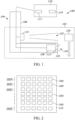
- the inspection system 100 includes a borescope unit 104 having a camera 106, a guide tube 108, and a light source 110.
- the light source 110 can be a standard light source integrated into the borescope unit 104.
- the light source 110 can be separate from the borescope unit 104.
- the light source 110 can include, but is not limited to, various different light emitting devices, such as a light emitting diode, an array of light emitting diodes, a xenon strobe light, a laser light source, a fiberoptic light transport, other direct local light sources, other indirect remote light sources, etc.
- various different light emitting devices such as a light emitting diode, an array of light emitting diodes, a xenon strobe light, a laser light source, a fiberoptic light transport, other direct local light sources, other indirect remote light sources, etc.
- the guide tube 108 is used to position the camera 106 and/or the light source 110 at a desired location relative to the complex system 102, for example inside the complex system 102.
- An end of the guide tube 108 is small and narrow and can be fed into difficult to reach locations, such as the inside of objects or mechanical devices, including jet engines or the like.
- the camera 106 When placed inside the complex system 102, the camera 106 then relays image data captured thereby back to an eyepiece and/or a display where the inside of the complex system 102 can be viewed and magnified.
- the light source 110 can be mounted on the guide tube 108 to be brought into position with respect to a target element 120 of the complex system 102.
- the borescope unit 104 can be replaced with a snake-arm robot, such as any of those disclosed in US Patents US8069747B2 , US7543518B2 , US11084169B2 and European Patents EP2170565B1 , EP3643451A1 , EP3643452A1 , each of which is incorporated by reference in their entirety.
- Snake-arm robots like borescopes, can be used for inspection of confined spaces.
- Snake-arm robots are electro-mechanical devices that include an arm with high degrees of freedom that can be controlled in a snake-like manner to follow a contoured path and avoid obstacles or comply when contacting obstacles.
- a snake arm robot typically includes a sequence of links that are driven by one or more motors and can move relative to one another to change the shape or curvature of the extension arm.
- the inspection system 100 may include a rigid or flexible elongated extension element that is sized and shaped to insert the camera 106 and the light source 110 into a confined space, such as the interior of a jet engine, to perform inspection.
- the light source 110 can be deployed in conjunction with non-confined space vision systems used to identify surface anomalies on an accessible portion of an object, for example, in a photo studio setting or the like.
- the inspection system 100 includes a sensor 114 and a controller 116 that is electrically coupled to the sensor 114, the camera 106, and the light source 110.
- the camera 106 is supported inside the guide tube 108 and includes an image sensor 112 with a field of view 118 for capturing one or more images of the target element 120 inside the complex system 102.
- the camera 106 can also include other optical elements, such as lenses and the like, that together with the image sensor 112 form an optical system with a resolution with respect to static (e.g. non-moving objects) that is defined in terms of line pairs per millimeter (Ip/mm).
- the controller 116 can include a programable processor 117 and a memory 119.
- the processor 117 may include, for example, a microprocessor, a system-on-a-chip, an application specific integrated circuit (ASIC), and/or a field programmable gate array (FPGA).
- the memory 119 may include, for example, an electrical charge-based storage media such as EEPROM or RAM, or other non-transitory computer readable media.
- the target element 120 can include one or more fan blades, compressor blades, turbine blades, or stator airfoils, such as nozzles and guide vanes, of the jet engine and/or other elements of the engine.
- the sensor 114 includes a sensing region 122 in which the sensor 114 detects movement of the target element 120 relative to the sensor 114, for example relative movement of a fan blade or shaft encoder to detect fan blade presence in multiple stages.
- the sensor 114 can be used to detect movement of another portion of the complex system 102 that is linked to the target element 120, for example a shaft or rotor of a jet engine.
- the sensor 114 can be coupled to the guide tube 108 for insertion into the complex system 102 along with the borescope unit 104. Additionally or alternatively, the sensor 114 can be a standalone device that is separately positionable relative to the complex system 102 proximate to the target element 120.
- the sensor 114 can include, but is not limited to, various contact and non-contact motion sensing devices, such as a whisker or electrical continuity sensor or switch, a roller type switch, an inductive proximity sensor, an optical proximity sensor, a hall effect sensor, an electrical continuity sensor, an ultrasonic sensor, etc. Where the sensor 114 is a contact sensor, such as a switch, the sensing region 122 can include a region in which the contact sensor physically traverses.
- the sensor 114 can include a roller located on the shaft or rotor, a motion flow sensor such as in an optical or laser mouse, a gyroscope or inertial measurement unit (IMU) attached to the shaft or rotor, a pull thread temporarily attached to the shaft or rotor, or other similar devices.
- a motion flow sensor such as in an optical or laser mouse
- IMU inertial measurement unit
- the image sensor 112 includes a plurality of light sensitive pixel elements 200 that are activatable.
- the plurality of light sensitive pixel elements 200 can be arranged in discrete rows 202A, 202B, 202C, 202Z, etc. as shown in FIG. 2 .
- the plurality of light sensitive pixel elements 200 are activatable by discrete row for a designated exposure time 300 ( FIG. 3 ) and on a rolling basis.
- each one of the activated light sensitive pixel elements 200 generates a digital signal representative of light viewable by that pixel element when active.
- the camera 106 and/or the controller 116 can convert those digital signals into image data that is viewable on a display device by an operator of the inspection system 100.
- the controller 116 can determine an activation time for the image sensor 112 (e.g., the time when the light sensitive pixel elements 200 are activated for the exposure time 300) based on motion of the target element 120 relative to the image sensor 112.
- the controller 116 can be configured to activate the image sensor 112 at the activation time.
- the relative motion of the image sensor 112 and the target element 120 encompasses any of movement of the target element 120 relative to a stationary image sensor 112, movement of the image sensor 112 relative to a stationary target element 120, and simultaneous movement of both the image sensor 112 and the target element 120 relative to each other.
- the relative movement includes lateral movement, transverse movement, movement in/out of a plane of view, and any combination thereof.
- the sensor 114 can be located such that the sensor 114 moves synchronously with either the image sensor 112 or the target element 120. However, in some embodiments, the sensor 114 may be stationary while both the image sensor 112 and the target element 120 are in motion.
- FIG. 3 shows the rolling activation of the discrete rows 202 whereby a topmost row (e.g., discrete row 202A of FIG. 2 ) is activated first in time with each row continuing to activate in sequence at an offset time from the prior row until the last row (e.g., discrete row 202Z of FIG. 2 ) is activated.
- a topmost row e.g., discrete row 202A of FIG. 2
- each row continuing to activate in sequence at an offset time from the prior row until the last row (e.g., discrete row 202Z of FIG. 2 ) is activated.
- each of the discrete rows 202 While activation of each of the discrete rows 202 is staggered, every one of the discrete rows 202 will be active to simultaneously capture light sensitivity data from the field of view 118 during a vertical blanking time 302. In some embodiments, multiple ones of the discrete rows 202 can be grouped for simultaneous activation. In these embodiments, the different groupings of the discrete rows 202 can be activated on a rolling staggered basis similar to that described above.
- the camera 106 and/or the controller 116 initiates a read-out period 304 for the captured light sensitivity data.
- the light sensitivity data is transferred from the image sensor 112 into a non-volatile memory for storage and later recall.
- Each block of the designated exposure time 300 and subsequent read-out period 304 correspond to a single captured image of the field of view 118.
- the exposure time 300 and the subsequent read-out period 304 can be repeated at a periodic frame rate to generate a sequence of images that are combinable into a video.
- the vertical blanking time 302 corresponds to a time gap period between each of the video frames
- the periodic frame rate corresponds to the activation time for the image sensor 112.
- activation of the light source 110 can include a single or repetitive periodic pulse 400 that has a timing synced to the start of the readout period 304 and that is activated for a preconfigured time duration that is less than the exposure time 300.
- the repetitive periodic pulse 400 can have a Pulse Repetition Frequency (PRF) that is synchronized to occur entirely during the vertical blanking time 302 before the rolling readout of the light sensitive pixel elements 200.
- PRF Pulse Repetition Frequency
- the PRF can be synchronized to occur at least partially outside of the vertical blanking time 302.
- the target element 120 will be frozen in different adjacent ones of the one or more images because of the rolling exposure and read-out of the light sensitive pixel elements 200. Therefore, these adjacent ones of the one or more images can be combined to generate a single composite image of the target element 120.
- the pulse activation of the light source 110 can be operated in connection with a non-rolling global shutter to reduce motion blur from the relative motion of the target element 120.
- each of the light sensitive pixel elements 200 are simultaneously read out. As such, no rolling shutter distortion is introduced in addition to motion blur caused by the relative movement of the target element 120.
- the pulse width (e.g., the preconfigured time duration the light source 110 is activated) is an order of magnitude smaller than the designated exposure time 300.
- the exposure time 300 is 8 milliseconds and the pulse width is 0.8 milliseconds.
- the difference in time magnitude enables the repetitive periodic pulse 400 to produce a global shutter like effect on the image sensor 112 to ensure that the motion of the target element 120 is frozen within the one or more images (e.g. motion blur is controlled or eliminated). It will be appreciated that different values or ranges of values for the exposure time 300 and the duration of the pulse width are available.
- the repetitive periodic pulse 400 acts as a global shutter because the ambient conditions relative to the target element 120 are dark or otherwise have de minimis visibility within the data recorded by the image sensor 112 absent light provided by a light source, such as the light source 110. As such, using the repetitive periodic pulse 400 can effectively lower the exposure time 300 without need to modify the time duration for which each of the light sensitive pixel elements 200 are active. This modification is useful where a speed of the relative motion of the target element 120 exceeds a maximum speed that can be frozen at either a hardware or resolution-limited minimum exposure time of the image sensor 112.
- the hardware-limited exposure time corresponds to the smallest possible value for the exposure time 300 that the image sensor 112 is capable of delivering
- the resolution-limited minimum exposure time corresponds to the smallest value for the exposure time 300 that the image sensor 112 can capture sufficient light to effectively generate images of the target element 120.
- the duration of the pulse width can be a function of a minimum resolution of the camera given a specific working distance under static (e.g. non-moving) conditions, and the speed of the relative motion between the image sensor 112 and the target element 120.
- the time value of the pulse width can be varied to ensure that the static resolution of the camera 106 is maintained under the relative motion conditions.
- the maximum duration for the pulse width (PW-MAX) in milliseconds that replicates the static resolution of the camera 106 at a specified working distance and minimum exposure time is defined by Equation 1 presented below, where R-CAM is the static resolution at the specific working distance in lp/mm and TS is the transverse speed of the target element 120 relative to the camera 106 in mm/s.
- PW ⁇ MAX 1000 2 ⁇ R ⁇ CAM ⁇ TS
- the repetitive periodic pulse 400 acts as a global shutter to freeze a frame that acts analogous to lowering the exposure time 300 of the image sensor 112 from the hardware- or resolution-limited minimum exposure time.
- Table 1 and Table 2 below with respect to an example image sensor at a working distance of 30mm and with a minimum exposure time of 4ms.
- Table 1 shows the final moving object resolution of an image in lp/mm for a continuous illumination over the 4ms exposure time for different relative speeds for the target element 120
- Table 2 shows the final moving object resolution of an image in lp/mm for illumination under different pulse width durations and different relative speeds for the target element 120.
- the final moving object resolution is the lesser of the static resolution of the camera (e.g. 10 lp/mm) or the minimum resolution induced by motion blur.
- the minimum resolution (R-MIN) induced by motion blur in lp/mm is in turn defined by Equation 2 below, where TS is the relative speed of the target element 120 (e.g. the transverse speed) in mm/s and EET is the effective exposure time in ms (e.g., the exposure time of 4ms for Table 1 or the pulse width time for Table 2).
- R ⁇ MIN 1000 2 ⁇ TS ⁇ EET
- CMOS Complementary metal-oxide-semiconductor
- utilizing the pulse width time as calculated according to Equation 1 above can enable non-degraded image capture of the target element 120 at increased relative speeds including but not limited to 20, 50, 66.66, 100, and 200 mm/s.
- utilizing a pulse width duration of at most 2.5 ms for a transverse speed of 20 mm/s can restore the full static resolution of the camera that would otherwise be degraded under a similar speed under constant illumination over the exposure time as seen in case 6 of Table 1.
- Table 3 shows the static resolution at working distances of 20, 30, and 40 mm of three different camera systems, namely a 90 degree field of view borescopic system, a 93 degree field of view 2 megapixel CMOS system, and a 29 degree field of view system.
- Equation 1 can be utilized to calculate the maximum pulse width duration needed to maintain the camera's static resolution when capturing images of the target element 120 under relative motion that is in excess of the maximum speed capturable by that camera at the hardware- or resolution-limited minimum exposure time.
- Table 3 Resolution (lp/mm) Distance (mm) 90 Deg FOV Borescopic 93 Deg FOV 2MP CMOS 29 Deg FOV 2MP CMOS 20 11.2 11.2 5 30 9 9 22.5 40 7.1 7.1 5
- the amount of illumination in lux output by the light source 110 can be varied, by the controller 116, as a function of the pulse width duration to ensure minimum quality in the image data.
- Table 4 below shows example minimum illumination values that will produce reference quality images at different pulse width durations.
- Table 4 shows the variation in lux that maintains image quality relative to a specific continuous illumination value at the hardware- or resolution-limited minimum exposure time (e.g. 700 lux at 4ms for the example shown in Table 4). This relationship is defined by the normalized resolution factor comparing the pulse width duration to the hardware- or resolution-limited minimum exposure time (e.g. the minimum exposure time divided by the pulse width duration) as identified in Table 4 below.
- the output illumination (L-OUT) for a specific pulse width duration can be defined generally by Equation 3 presented below, where L-CON is the continuous illumination in lux that produces ideal images at the hardware- or resolution-limited minimum exposure time (ET-MIN) and PWD is the desired pulse width duration. This relationship can also be seen with respect to FIG. 5 .
- the ambient lighting conditions that would result in non-de minimis light being captured by the image sensor 112 can be corrected for by placing filters or other similar light blocking mechanisms on the camera 106.
- filters or other similar light blocking mechanisms For example, Neutral Density (ND) Filters can be added to the camera 106 to minimize the number of photons that reach the image sensor 112.
- the intensity of the pulse illumination is increased to correct or offset for the presence of ND filters in the imaging path so as to enable generating a good signal to noise ratio in images formed from the light that reaches the image sensor 112.
- activation of the light source 110 is accomplished by the controller 116.
- the controller 116 can synchronize the activation of the light source 110 with the activation time of the image sensor 112 and with the movement of the target element 120.
- the synchronization is accomplished using a trigger signal or condition such as a detection signal that is sent or transmitted from the sensor 114, is received at the controller 116, and indicates the presence of movement within the sensing region 122.
- the detection signal can detect a position of a fan blade, sync the activation of the light source with the frame rate of the camera 106, and trigger activation of the light source 110 at short pulses.
- the controller 116 utilizes a time delay as measured from receipt of the detection signal to synchronize the activation of the light source 110 with the activation of the image sensor 112. For example, as seen in FIG. 6 , where the target element 120 is being moved through the sensing region 122 at a constant RPM (e.g., by use of a precise turning tool) a time delay 500 from receipt of the detection signal to a time for a frame (dT f-1 ) one frame before a key frame (dT f ) that includes the target element 120 is set based on the constant revolutions per minute associated with the target element 120.
- a time delay 500 from receipt of the detection signal to a time for a frame (dT f-1 ) one frame before a key frame (dT f ) that includes the target element 120 is set based on the constant revolutions per minute associated with the target element 120.
- the image sensor 112 can be activated until a frame (dT f+1 ) one frame after the key frame (dT f ).
- a time delay 600 from receipt of the detection signal to a time for a frame (dT f-10 ) ten frames before the key frame (dTf) is set based on an on average revolutions per minute associated with the target element 120.
- the number of frames captured before the key frame (dTf) is determined as a function of an observed standard deviation in the relative motion between the image sensor 113 and the target element 120 and, thus, is not limited to the examples of 1 and 10 frames discussed above.
- the controller 116 determines the average revolutions per minute from repeated receptions of the detection signal.
- the time delays 500 and 600 can be determined using time and/or distance synchronization.
- time synchronization can include utilizing a known travel time between a location of the sensor 114 and the field of view 118 and distance synchronization can include utilizing a known distance between a location of the sensor 114 and the field of view 118.
- the movement detected by the sensor 114 can be the movement of the target element 120 that is captured in the one or more images or movement of another element associated with the target element 120.
- the movement that initiates the blade detection signal can be movement of a preceding or succeeding element in the group.
- the target element 120 includes a fan blade of a jet engine
- a trigger for the controller to activate the image sensor 112 and capture the one or more images of that specific fan blade can be the presence of another of the fan blades within the sensing region 122.
- the motion detected by the sensor 114 can be motion of the shaft or rotor of the engine.
- the senor 114 is configured to detect movement relative to a single common reference point for each of the multiple stages.
- the single common reference point can include a shaft 700 of the engine or the movement of blades within one stage (e.g., stage S5 of stages S5, S6, S7, S8, S9, etc.).
- illumination and imaging of each stage can be done simultaneously via multiple borescope units 104 and using a known clocking of each of the stages. Furthermore, in some embodiments, alternating ones of the stages can be imaged at the same time to avoid light bleed between adjoining ones of the stages.
- the sensor 114 can be omitted.
- synchronization of the repetitive periodic pulse 400 with activation of the image sensor 112 and the movement of the target element 120 can be accomplished using a known repeating and periodic movement relative to the field of view, and the activation of the light source 110 is initiated based on a known frequency and duration of the repeating periodic motion of the target element 120 (e.g., a known clocking rate of the target element 120).
- the synchronization of the repetitive periodic pulse 400 with activation of the image sensor 112 and the movement of the target element 120 can be accomplished using the image sensor 112 and a time delay calibration method.
- FIG. 9 is a flow diagram of an embodiment of the time delay calibration method 800.
- the method 800 can include activating 802, after a time delay, the light source 110 to emit pulsed illuminations that illuminate the field of view 118 of the image sensor 112 for a preconfigured time duration.
- the time delay calibration method 800 includes initiating 804 repeated activation of the plurality of light sensitive pixel elements 200 for the designated exposure time 300, in the discrete rows 202, and on the rolling basis to capture light sensitivity data from the field of view 118 so as to capture the plurality of video frames.
- the imitating 804 can include estimating a frame rate of the image sensor 112.
- the method 800 includes evaluating 806 the plurality of video frames for determining 808 whether the activating 802 of the light source 110 was synchronized with the plurality of video frames.
- the method 800 includes identifying or estimating 810 a proximate delay (e.g., a deltaT) between the capture of the plurality of video frames and the activating 802 of the light source 110 and updating the time delay based on the proximate delay, and continuing the activating 802, initiating 804, evaluating 806, determining 808, and estimating 810 until the light source 110 is synchronized with the plurality of video frames.
- a proximate delay e.g., a deltaT
- the activating 906 can be synchronized to the activating 904 of the image sensor 112 and with the movement of the target element 120 via a time delay such as the calibrated time delay value from the method 800 or the time delays values 500 and 600 from receipt of the detection signal from the sensor 114.
- a pulse illumination imaging system comprising: an image sensor having a plurality of light sensitive pixel elements that are activatable, for a designated exposure time to capture one or more images of a field of view of the image sensor; a light source; and a controller configured to: determine an activation time to activate the image sensor based on motion of a target element relative to the image sensor; activate the image sensor at the activation time; and activate the light source during the designated exposure time of the image sensor to produce a pulse having a preconfigured time duration that is less than the exposure time of the image sensor.
- the activation time includes a repeating frame rate for activating the image sensor, and where the controller is configured to periodically pulse the light source in sync relative to the frame rate and the motion of the target element.
- controller is further configured to synchronize the activation of the light source with a vertical blanking time of the image sensor so as to capture the target element entirely within a single one of the one or more images.
- the preconfigured time duration is determined as a function of a static resolution of a camera that includes the image sensor and a known maximum speed of the motion of the target element relative to the image sensor.
- the designated exposure time is in a range of between 4 milliseconds and 8 milliseconds and the preconfigured time duration is in a range of between 0.25 milliseconds and 2.5 milliseconds.
- the designated exposure time is in a range of between 4 milliseconds and 64 milliseconds and the preconfigured time duration is in a range of between 0.1 milliseconds and 4 milliseconds.
- any preceding clause further comprising a sensor configured to transmit a detection signal to the controller when the sensor detects movement within a sensing region of the sensor.
- the movement the controller is configured to use to determine the activation time includes an average revolutions per minute of the target element determined by the controller from repeated receptions of the detection signal, and wherein the controller is configured to determine a time delay from receipt of the detection signal based on an average revolutions per minute associated with the target element and activate the light source following the time delay.
- the movement the controller is configured to use to determine the activation time includes a known revolutions per minute of the target element, and wherein the controller is configured to determine a time delay from receipt of the detection signal based on the known revolutions per minute associated with the target element and activate the light source following the time delay.
- the target element includes one or more airfoils within multiple stages of an engine, and wherein the sensor is configured to detect movement relative to a single common reference point for each of the multiple stages.
- the senor is selected from one of a switch, an inductive proximity sensor, an optical proximity sensor, a hall effect sensor, an electrical continuity sensor, and an ultrasonic sensor.
- the motion the controller is configured to use to determine the activation time includes a known frequency and duration of a repeating and periodic movement of the target element relative to the image sensor, wherein the controller is configured to activate the light source based on a time delay as measured relative to activation of the image sensor and initiation of the repeating and periodic movement of the target element.
- the light source is selected from one of a light emitting diode, an array of light emitting diodes, a xenon strobe light, a laser light source, and a fiberoptic transport.
- a method for inspecting a target element comprising: determining an activation time to activate an image sensor based on motion of a target element relative to the image sensor; activating, at the activation time, a plurality of light sensitive pixel elements of the image sensor for a designated exposure time to capture one or more images of a field of view of the image sensor; and activating a light source during the designated exposure time of the image sensor to produce a pulse having a preconfigured time duration that is less than the exposure time of the image sensor.
- any preceding clause further comprising synchronizing the activation of the light source with a vertical blanking time of the image sensor so as to capture the target element entirely within a single one of the one or more images.
- any preceding clause further comprising determining the preconfigured time duration as a function of a static resolution of a camera that includes the image sensor and a known maximum speed of the motion of the target element relative to the image sensor.
- any preceding clause further comprising: detecting motion within a sensing region of a sensor; receiving a detection signal from the sensor responsive to the detecting; and activating the light source after a time delay following receipt of the detection signal.
- any preceding clause further comprising: receiving a known frequency and duration of a repeating and periodic movement of the target element; determining the activation time from the known frequency and duration of the repeating and periodic movement; determining a time delay for activating the light source as measured relative to activation of the image sensor and initiation of the repeating and periodic movement of the target element; and activating the light source after the time delay.
- a method for calibrating a light pulse illumination time delay for an inspection system comprising: activating, after a time delay, a light source to illuminate a field of view of an image sensor for a preconfigured time duration; initiating repeated activation of a plurality of light sensitive pixel elements of the image sensor for a designated exposure time to capture light sensitivity data from the field of view so as to capture a plurality of video frames; evaluating the plurality of video frames to determine whether the activating of the light source was synchronized with the plurality of video frames; and when the activating of the light source is not synchronized, identifying a proximate delay between the capture of the plurality of video frames and the activating of the light source and updating the time delay based on the proximate delay.
- the static resolution of the camera is selected from one of 10 lp/mm at a distance of 30mm from the camera to the target elment, 11.2 lp/mm at a distance of 20 mm from the camera to the target element, and 22.5 lp/mm at a distance of 30mm from the camera to the target element.
- a maximum duration PW-MAX for the pulse width in milliseconds that replicates the static resolution of the camera at a specified working distance and minimum exposure time is defined as 1000/(2*R-CAM*TS), where R-CAM is the static resolution of the camera at the specific working distance in lp/mm and TS is the transverse speed of the target element relative to the camera in mm/s.
- an amount of light emitted by the light source L-OUT is defined as L-CON*ET-MIN/PWD, where L-CON is a continuous illumination in lux that produces ideal images at a hardware or resolution limited minimum exposure time (ET-MIN) of the camera and PWD is preconfigured time duration for which the light source is activated.
- L-CON is a continuous illumination in lux that produces ideal images at a hardware or resolution limited minimum exposure time (ET-MIN) of the camera and PWD is preconfigured time duration for which the light source is activated.
- the motion of the target element relative to the image sensor includes one of movement of the target element relative to a stationary image sensor, movement of the image sensor relative to a stationary target element, and simultaneous movement of both the image sensor and the target element relative to each other.
- the relative movement includes lateral movement, transverse movement, movement in/out of a plane of view, and any combination thereof.
- a computer-readable medium comprising computer-executable instructions, which, when executed by one or more processors of a controller for a pulse illumination imaging system, cause the controller to: determine an activation time to activate an image sensor based on relative motion between a target element and the image sensor; activate the image sensor at the activation time; and activate a light source during a designated exposure time of the image sensor to produce a pulse having a preconfigured time duration that is less than the designated exposure time of the image sensor.
- a controller for a pulse illumination imaging system comprising: one or more non-transitory memory devices; and one or more processors configured to: determine an activation time to activate an image sensor based on relative motion between a target element and the image sensor; activate the image sensor at the activation time; and activate a light source during a designated exposure time of the image sensor to produce a pulse having a preconfigured time duration that is less than the designated exposure time of the image sensor.
- a controller for a pulse illumination imaging system comprising: one or more non-transitory memory devices; and one or more processors configured to: determine an activation time to activate an image sensor based on relative motion between a target element and the image sensor; activate the image sensor at the activation time; and activate a light source during a designated exposure time of the image sensor to produce a pulse illumination with a pulse repetition frequency that is synced with a frame rate of the image sensor, and wherein the pulse illumination has a preconfigured time duration that is less than the designated exposure time of the image sensor.
Landscapes
- Engineering & Computer Science (AREA)
- Multimedia (AREA)
- Signal Processing (AREA)
- Studio Devices (AREA)
- Length Measuring Devices By Optical Means (AREA)
Abstract
Description
- This application claims benefit of the following
IN Provisional Application 202311017364 filed on March 15, 2023 - These teachings relate generally to motion imaging and more particularly to a pulse illumination imaging for motion capture of a target element.
- Visual artifacts are anomalies apparent in visual representations such as photography. Motion blur is an artifact that results when the image being recorded moves during the recording of a single exposure. Capturing fast moving objects with a rolling shutter camera can further introduce wobble, skew, spatial aliasing, and temporal aliasing, reducing the overall clarity and accuracy of the captured images.
- Various needs are at least partially met through provision of the pulse illumination imaging system for motion capture of a target element described in the following detailed description, particularly when studied in conjunction with the drawings. A full and enabling disclosure of the aspects of the present description, including the best mode thereof, directed to one of ordinary skill in the art, is set forth in the specification, which refers to the appended figures, in which:
-
FIG. 1 shows a block diagram of an imaging system as configured in accordance with various embodiments of these teachings; -
FIG. 2 shows a schematic diagram of an image sensor as configured in accordance with various embodiments of these teachings; -
FIG. 3 shows a timing diagram for pulse illumination and image capture as configured in accordance with various embodiments of these teachings; -
FIG. 4 shows a timing diagram for pulse illumination and image capture as configured in accordance with various embodiments of these teachings; -
FIG. 5 shows a graph of normalized illumination values in accordance with various embodiments of these teachings; -
FIG. 6 shows a timing diagram for pulse illumination and image capture as configured in accordance with various embodiments of these teachings; -
FIG. 7 shows a timing diagram for pulse illumination and image capture as configured in accordance with various embodiments of these teachings; -
FIG. 8 is a schematic diagram of an imaging system in conjunction with a multistage jet engine as configured in accordance with various embodiments of these teachings; -
FIG. 9 shows a flow diagram for a calibration method as configured in accordance with various embodiments of these teachings; and -
FIG. 10 shows a flow diagram for an operating method as configured in accordance with various embodiments of these teachings. - Elements in the figures are illustrated for simplicity and clarity and have not necessarily been drawn to scale. For example, the dimensions and/or relative positioning of some of the elements in the figures may be exaggerated relative to other elements to help to improve understanding of various embodiments of the present teachings. Also, common but well-understood elements that are useful or necessary in a commercially feasible embodiment are often not depicted in order to facilitate a less obstructed view of these various embodiments of the present teachings. Certain actions and/or steps may be described or depicted in a particular order of occurrence while those skilled in the art will understand that such specificity with respect to sequence is not actually required.
- The terms and expressions used herein have the ordinary technical meaning as is accorded to such terms and expressions by persons skilled in the technical field as set forth above except where different specific meanings have otherwise been set forth herein. The word "or" when used herein shall be interpreted as having a disjunctive construction rather than a conjunctive construction unless otherwise specifically indicated. The terms "coupled," "fixed," "attached to," and the like refer to both direct coupling, fixing, or attaching, as well as indirect coupling, fixing, or attaching through one or more intermediate components or features, unless otherwise specified herein.
- The singular forms "a", "an", and "the" include plural references unless the context clearly dictates otherwise.
- Approximating language, as used herein throughout the specification and claims, is applied to modify any quantitative representation that could permissibly vary without resulting in a change in the basic function to which it is related. Accordingly, a value modified by a term or terms such as "about", "approximately", and "substantially", are not to be limited to the precise value specified. In at least some instances, the approximating language may correspond to the precision of an instrument for measuring the value, or the precision of the methods or machines for constructing or manufacturing the components and/or systems. For example, the approximating language may refer to being within a 10 percent margin.
- Borescope inspection is typically done periodically to assess the distress level of components inside a fully or partially assembled aircraft engine. Imaging inspections can be done under diffused lighting with continuous illumination and are performed in motion, with either the component moving while the camera is stationary or the camera moving with respect to the component. However, the still and video images captured under these conditions can include imaging artifacts, such as motion blur or the like, introduced due to the motion of the moving elements. Imaging artifacts can be corrected using various image processing techniques, such as blind deconvolution, which characterizes the speed and angle of motion using image processing methods to estimate a point spread function for motion artifacts. Conventional techniques for artifact correction are commonly very processing intensive, take significant time to be applied, and can require layers of additional post processing to correct for other artifacts introduced after, for example, deconvolution. These are all significant challenges in the context of aviation application settings.
- Generally speaking, the various aspects of the present disclosure can be employed with a system that includes an image sensor and a light source that is activated to pulse at a specific time and for a specific duration so as to produce a freeze frame effect of a rotating target element, such as a jet engine fan blade, within one or more images captured by the image sensor. The systems of the present disclosure can produce consistent images from one inspection to another irrespective of the skill level of the operator. In some embodiments, systems and methods described herein use high intensity pulse illumination with a pulse repetition frequency (PRF) of the pulse synced with a frame rate of the imaging system and the pulse width an order of magnitude smaller than the exposure time of the camera. The described method can compensate for the effect of rolling shutter and motion blur artifacts and helps in capturing images at the full resolution capability of the imaging system thus improving the clarity of captured images.
- The foregoing and other benefits may become clearer upon making a thorough review and study of the following detailed description. Referring now to the drawings, and in particular to
FIG. 1 , aninspection system 100 that is compatible with many of these teachings and for use in inspecting acomplex system 102 will now be presented. Theinspection system 100 includes aborescope unit 104 having acamera 106, aguide tube 108, and alight source 110. In some embodiments, thelight source 110 can be a standard light source integrated into theborescope unit 104. However, in some embodiments, thelight source 110 can be separate from theborescope unit 104. Thelight source 110 can include, but is not limited to, various different light emitting devices, such as a light emitting diode, an array of light emitting diodes, a xenon strobe light, a laser light source, a fiberoptic light transport, other direct local light sources, other indirect remote light sources, etc. - The
guide tube 108 is used to position thecamera 106 and/or thelight source 110 at a desired location relative to thecomplex system 102, for example inside thecomplex system 102. An end of theguide tube 108 is small and narrow and can be fed into difficult to reach locations, such as the inside of objects or mechanical devices, including jet engines or the like. When placed inside thecomplex system 102, thecamera 106 then relays image data captured thereby back to an eyepiece and/or a display where the inside of thecomplex system 102 can be viewed and magnified. In some embodiments, thelight source 110 can be mounted on theguide tube 108 to be brought into position with respect to atarget element 120 of thecomplex system 102. - In some embodiments, the
borescope unit 104 can be replaced with a snake-arm robot, such as any of those disclosed in US PatentsUS8069747B2 ,US7543518B2 ,US11084169B2 EP2170565B1 ,EP3643451A1 ,EP3643452A1 , each of which is incorporated by reference in their entirety. Snake-arm robots, like borescopes, can be used for inspection of confined spaces. Snake-arm robots are electro-mechanical devices that include an arm with high degrees of freedom that can be controlled in a snake-like manner to follow a contoured path and avoid obstacles or comply when contacting obstacles. A snake arm robot typically includes a sequence of links that are driven by one or more motors and can move relative to one another to change the shape or curvature of the extension arm. In some embodiments, theinspection system 100 may include a rigid or flexible elongated extension element that is sized and shaped to insert thecamera 106 and thelight source 110 into a confined space, such as the interior of a jet engine, to perform inspection. It will also be appreciated that thelight source 110 can be deployed in conjunction with non-confined space vision systems used to identify surface anomalies on an accessible portion of an object, for example, in a photo studio setting or the like. - The
inspection system 100 includes asensor 114 and acontroller 116 that is electrically coupled to thesensor 114, thecamera 106, and thelight source 110. Thecamera 106 is supported inside theguide tube 108 and includes animage sensor 112 with a field ofview 118 for capturing one or more images of thetarget element 120 inside thecomplex system 102. Thecamera 106 can also include other optical elements, such as lenses and the like, that together with theimage sensor 112 form an optical system with a resolution with respect to static (e.g. non-moving objects) that is defined in terms of line pairs per millimeter (Ip/mm). In particular, lp/mm refers to an ability of the optical system to fully distinguish between a number of separately delineated same-sized black and white pairs of lines (i.e., the line pairs) presented in a specific spatial region a certain mm in length. As seen inFIG. 1 , thecontroller 116 can include aprogramable processor 117 and amemory 119. Theprocessor 117 may include, for example, a microprocessor, a system-on-a-chip, an application specific integrated circuit (ASIC), and/or a field programmable gate array (FPGA). Thememory 119 may include, for example, an electrical charge-based storage media such as EEPROM or RAM, or other non-transitory computer readable media. - Where the
complex system 102 includes a jet engine or the like, thetarget element 120 can include one or more fan blades, compressor blades, turbine blades, or stator airfoils, such as nozzles and guide vanes, of the jet engine and/or other elements of the engine. Furthermore, thesensor 114 includes asensing region 122 in which thesensor 114 detects movement of thetarget element 120 relative to thesensor 114, for example relative movement of a fan blade or shaft encoder to detect fan blade presence in multiple stages. In some embodiments, thesensor 114 can be used to detect movement of another portion of thecomplex system 102 that is linked to thetarget element 120, for example a shaft or rotor of a jet engine. Thesensor 114 can be coupled to theguide tube 108 for insertion into thecomplex system 102 along with theborescope unit 104. Additionally or alternatively, thesensor 114 can be a standalone device that is separately positionable relative to thecomplex system 102 proximate to thetarget element 120. Thesensor 114 can include, but is not limited to, various contact and non-contact motion sensing devices, such as a whisker or electrical continuity sensor or switch, a roller type switch, an inductive proximity sensor, an optical proximity sensor, a hall effect sensor, an electrical continuity sensor, an ultrasonic sensor, etc. Where thesensor 114 is a contact sensor, such as a switch, thesensing region 122 can include a region in which the contact sensor physically traverses. In some embodiments, where thesensor 114 is triggered off of a rotor or shaft of thecomplex system 102, thesensor 114 can include a roller located on the shaft or rotor, a motion flow sensor such as in an optical or laser mouse, a gyroscope or inertial measurement unit (IMU) attached to the shaft or rotor, a pull thread temporarily attached to the shaft or rotor, or other similar devices. - With reference now to
FIG. 2 , theimage sensor 112 includes a plurality of lightsensitive pixel elements 200 that are activatable. The plurality of lightsensitive pixel elements 200 can be arranged indiscrete rows FIG. 2 . In some embodiments, the plurality of lightsensitive pixel elements 200 are activatable by discrete row for a designated exposure time 300 (FIG. 3 ) and on a rolling basis. In particular, when activated, each one of the activated lightsensitive pixel elements 200 generates a digital signal representative of light viewable by that pixel element when active. Then, thecamera 106 and/or thecontroller 116 can convert those digital signals into image data that is viewable on a display device by an operator of theinspection system 100. In some embodiments, thecontroller 116 can determine an activation time for the image sensor 112 (e.g., the time when the lightsensitive pixel elements 200 are activated for the exposure time 300) based on motion of thetarget element 120 relative to theimage sensor 112. Furthermore, thecontroller 116 can be configured to activate theimage sensor 112 at the activation time. - It will be appreciated that the relative motion of the
image sensor 112 and thetarget element 120 encompasses any of movement of thetarget element 120 relative to astationary image sensor 112, movement of theimage sensor 112 relative to astationary target element 120, and simultaneous movement of both theimage sensor 112 and thetarget element 120 relative to each other. The relative movement includes lateral movement, transverse movement, movement in/out of a plane of view, and any combination thereof. Furthermore, where utilized, thesensor 114 can be located such that thesensor 114 moves synchronously with either theimage sensor 112 or thetarget element 120. However, in some embodiments, thesensor 114 may be stationary while both theimage sensor 112 and thetarget element 120 are in motion. - With reference to
FIGS. 1, 2 ,3, and 4 , operation of thecamera 106, theimage sensor 112, and thelight source 110 will be discussed in more detail. As seen inFIG. 3 , the lightsensitive pixel elements 200 are activated for theexposure time 300. Furthermore,FIG. 3 shows the rolling activation of thediscrete rows 202 whereby a topmost row (e.g.,discrete row 202A ofFIG. 2 ) is activated first in time with each row continuing to activate in sequence at an offset time from the prior row until the last row (e.g.,discrete row 202Z ofFIG. 2 ) is activated. While activation of each of thediscrete rows 202 is staggered, every one of thediscrete rows 202 will be active to simultaneously capture light sensitivity data from the field ofview 118 during avertical blanking time 302. In some embodiments, multiple ones of thediscrete rows 202 can be grouped for simultaneous activation. In these embodiments, the different groupings of thediscrete rows 202 can be activated on a rolling staggered basis similar to that described above. - After the
vertical blanking time 302 and the complete exposure of the top one of thediscrete rows 202, thecamera 106 and/or thecontroller 116 initiates a read-outperiod 304 for the captured light sensitivity data. Specifically, during the read-outperiod 304, the light sensitivity data is transferred from theimage sensor 112 into a non-volatile memory for storage and later recall. Each block of the designatedexposure time 300 and subsequent read-outperiod 304 correspond to a single captured image of the field ofview 118. Furthermore, as seen inFIG. 4 theexposure time 300 and the subsequent read-outperiod 304 can be repeated at a periodic frame rate to generate a sequence of images that are combinable into a video. In such embodiments, thevertical blanking time 302 corresponds to a time gap period between each of the video frames, and the periodic frame rate corresponds to the activation time for theimage sensor 112. - In some embodiments, activation of the
light source 110 can include a single or repetitiveperiodic pulse 400 that has a timing synced to the start of thereadout period 304 and that is activated for a preconfigured time duration that is less than theexposure time 300. For example, as seen inFIG. 4 , the repetitiveperiodic pulse 400 can have a Pulse Repetition Frequency (PRF) that is synchronized to occur entirely during thevertical blanking time 302 before the rolling readout of the lightsensitive pixel elements 200. This timing can ensure that thetarget element 120 is captured entirely within a single one of the one or more images captured by thecamera 106 because the light from thelight source 110 will be emitted solely when all of thediscrete rows 202 are active. In some embodiments, the PRF can be synchronized to occur at least partially outside of thevertical blanking time 302. In these embodiments, thetarget element 120 will be frozen in different adjacent ones of the one or more images because of the rolling exposure and read-out of the lightsensitive pixel elements 200. Therefore, these adjacent ones of the one or more images can be combined to generate a single composite image of thetarget element 120. It will also be appreciated that the pulse activation of thelight source 110 can be operated in connection with a non-rolling global shutter to reduce motion blur from the relative motion of thetarget element 120. For such global shutter variants of thecamera 106, each of the lightsensitive pixel elements 200 are simultaneously read out. As such, no rolling shutter distortion is introduced in addition to motion blur caused by the relative movement of thetarget element 120. - In some embodiments, the pulse width (e.g., the preconfigured time duration the
light source 110 is activated) is an order of magnitude smaller than the designatedexposure time 300. For example, in some embodiments theexposure time 300 is 8 milliseconds and the pulse width is 0.8 milliseconds. The difference in time magnitude enables the repetitiveperiodic pulse 400 to produce a global shutter like effect on theimage sensor 112 to ensure that the motion of thetarget element 120 is frozen within the one or more images (e.g. motion blur is controlled or eliminated). It will be appreciated that different values or ranges of values for theexposure time 300 and the duration of the pulse width are available. For example, theexposure time 300 can be in a range of between 4 milliseconds and 64 milliseconds and the time duration for the pulse width can be in a range of between 0.1 milliseconds and 4 milliseconds. In some embodiments, theexposure time 300 is in a range of between 4 milliseconds and 8 milliseconds and the time duration for the pulse width is in a range of between 0.25 milliseconds and 2.5 milliseconds. - The repetitive
periodic pulse 400 acts as a global shutter because the ambient conditions relative to thetarget element 120 are dark or otherwise have de minimis visibility within the data recorded by theimage sensor 112 absent light provided by a light source, such as thelight source 110. As such, using the repetitiveperiodic pulse 400 can effectively lower theexposure time 300 without need to modify the time duration for which each of the lightsensitive pixel elements 200 are active. This modification is useful where a speed of the relative motion of thetarget element 120 exceeds a maximum speed that can be frozen at either a hardware or resolution-limited minimum exposure time of theimage sensor 112. The hardware-limited exposure time corresponds to the smallest possible value for theexposure time 300 that theimage sensor 112 is capable of delivering, and the resolution-limited minimum exposure time corresponds to the smallest value for theexposure time 300 that theimage sensor 112 can capture sufficient light to effectively generate images of thetarget element 120. - Furthermore, the duration of the pulse width can be a function of a minimum resolution of the camera given a specific working distance under static (e.g. non-moving) conditions, and the speed of the relative motion between the
image sensor 112 and thetarget element 120. In particular, the time value of the pulse width can be varied to ensure that the static resolution of thecamera 106 is maintained under the relative motion conditions. For example, the maximum duration for the pulse width (PW-MAX) in milliseconds that replicates the static resolution of thecamera 106 at a specified working distance and minimum exposure time is defined byEquation 1 presented below, where R-CAM is the static resolution at the specific working distance in lp/mm and TS is the transverse speed of thetarget element 120 relative to thecamera 106 in mm/s.
- As discussed above, the repetitive
periodic pulse 400 acts as a global shutter to freeze a frame that acts analogous to lowering theexposure time 300 of theimage sensor 112 from the hardware- or resolution-limited minimum exposure time. The advantage of this approach can be seen with reference to Table 1 and Table 2 below with respect to an example image sensor at a working distance of 30mm and with a minimum exposure time of 4ms. Specifically, Table 1 shows the final moving object resolution of an image in lp/mm for a continuous illumination over the 4ms exposure time for different relative speeds for thetarget element 120 and Table 2 shows the final moving object resolution of an image in lp/mm for illumination under different pulse width durations and different relative speeds for thetarget element 120. As seen in Tables 1 and 2, the final moving object resolution is the lesser of the static resolution of the camera (e.g. 10 lp/mm) or the minimum resolution induced by motion blur. The minimum resolution (R-MIN) induced by motion blur in lp/mm is in turn defined byEquation 2 below, where TS is the relative speed of the target element 120 (e.g. the transverse speed) in mm/s and EET is the effective exposure time in ms (e.g., the exposure time of 4ms for Table 1 or the pulse width time for Table 2).
- With reference to Table 1, it can be seen that under continuous illumination the maximum possible relative speed achievable for the
target element 120 without producing image degradation as compared with the static resolution of thecamera 106 configured as Complementary metal-oxide-semiconductor (CMOS) rolling output optical system under continuous illumination is 12.5 mm/s (e.g. at a relative movement of 12.5 mm/s R-MIN is equal to the static resolution of the camera). Specifically, the speeds of 16 and 20 mm/s incases Equation 1 above can enable non-degraded image capture of thetarget element 120 at increased relative speeds including but not limited to 20, 50, 66.66, 100, and 200 mm/s. With specific reference to case 11 of Table 2, it is shown that employing a pulse width duration of at most 2.5 ms for a transverse speed of 20 mm/s can restore the full static resolution of the camera that would otherwise be degraded under a similar speed under constant illumination over the exposure time as seen incase 6 of Table 1.Table 1 TABLE 1 - Continuous Illumination over entire Exposure Time Case 1 Case 2Case 3Case 4Case 5Case 6Min Camera Exposure Time (ms) 4.00 4.00 4.00 4.00 4.00 4.00 Transverse Speed (mm/s) 1.00 4.00 8.00 12.50 16.00 20.00 Min resolution induced due to motion blur (lp/mm) 125.00 31.25 15.63 10.00 7.81 6.25 Resolution of Image of a moving object at 30mm (lp/mm) 10.00 10.00 10.00 10.00 7.81 6.25 Table 2 TABLE 2 - Pulse Width Illumination Independent of Camera Exposure Time (at 4ms) Case 7Case 8Case 9 Case 10Case 11 Pulse Width (ms) 0.25 0.50 0.75 1.00 2.50 Transverse Speed (mm/s) 200.00 100.00 66.66 50.00 20.00 Min resolution of the image due to motion blur (lp/mm) 10.00 10.00 10.00 10.00 10.00 Resolution of Image of a moving object at 30mm (lp/mm) 10.00 10.00 10.00 10.00 10.00 - It will be understood that cameras having different minimal resolutions and working distances from the example of 10 lp/mm at a 30mm working distance may also be utilized. In particular, Table 3, presented below, shows the static resolution at working distances of 20, 30, and 40 mm of three different camera systems, namely a 90 degree field of view borescopic system, a 93 degree field of
view 2 megapixel CMOS system, and a 29 degree field of view system. As seen below, the 90 degree field of view borescopic system and the 93 degree field ofview 2 megapixel CMOS system both produce a best minimum resolution of 11.2 lp/mm at a working distance of 20mm, while the 29 degree field of view CMOS system produces a best minimum resolution of 22.5 lp/mm at a working distance of 30mm. For each of these possible systems and other similar camera imaging systems known in the art,Equation 1 above can be utilized to calculate the maximum pulse width duration needed to maintain the camera's static resolution when capturing images of thetarget element 120 under relative motion that is in excess of the maximum speed capturable by that camera at the hardware- or resolution-limited minimum exposure time.Table 3 Resolution (lp/mm) Distance (mm) 90 Deg FOV Borescopic 93 Deg FOV 2MP CMOS 29 Deg FOV 2MP CMOS 20 11.2 11.2 5 30 9 9 22.5 40 7.1 7.1 5 - In some embodiments, the amount of illumination in lux output by the
light source 110 can be varied, by thecontroller 116, as a function of the pulse width duration to ensure minimum quality in the image data. Table 4 below shows example minimum illumination values that will produce reference quality images at different pulse width durations. In particular, Table 4 shows the variation in lux that maintains image quality relative to a specific continuous illumination value at the hardware- or resolution-limited minimum exposure time (e.g. 700 lux at 4ms for the example shown in Table 4). This relationship is defined by the normalized resolution factor comparing the pulse width duration to the hardware- or resolution-limited minimum exposure time (e.g. the minimum exposure time divided by the pulse width duration) as identified in Table 4 below. It will be appreciated that other camera and imagining systems can have different ideal continuous illumination values and hardware- or resolution-limited minimum exposure times. As such, the output illumination (L-OUT) for a specific pulse width duration can be defined generally byEquation 3 presented below, where L-CON is the continuous illumination in lux that produces ideal images at the hardware- or resolution-limited minimum exposure time (ET-MIN) and PWD is the desired pulse width duration. This relationship can also be seen with respect toFIG. 5 .Table 4 Illumination (lux) Pulse duration (s) lux-sec Pulse duration (ms) Normalized- illumination factor 700 0.004 2.8 4 1 1400 0.002 2.8 2 2 2800 0.001 2.8 1 4 3500 0.0008 2.8 0.8 5 4666.666667 0.0006 2.8 0.6 6.67 7000 0.0004 2.8 0.4 10 14000 0.0002 2.8 0.2 20 
- It will also be appreciated that in some embodiments, the
light source 110 can be configured to output for all pulse width durations a single illumination value corresponding to a minimum pulse width duration of theinspection system 100. For example, in the context of Table 4 above, thelight source 110 can be configured to always output light with a luminance of 14000 lux. It will further be appreciated that in some embodiments, theimage sensor 112 and thelight source 110 can utilize the non-visible light spectrum (e.g., ultraviolet or infrared light) rather than visible light. Using non-visible light can enable use of theinspection system 100 on target elements where the ambient lighting conditions would result in non-de minimis light being captured by theimage sensor 112 outside of when the repetitiveperiodic pulse 400 is active. Additionally or alternatively, in some embodiments, the ambient lighting conditions that would result in non-de minimis light being captured by theimage sensor 112 can be corrected for by placing filters or other similar light blocking mechanisms on thecamera 106. For example, Neutral Density (ND) Filters can be added to thecamera 106 to minimize the number of photons that reach theimage sensor 112. Furthermore, in these embodiments, the intensity of the pulse illumination is increased to correct or offset for the presence of ND filters in the imaging path so as to enable generating a good signal to noise ratio in images formed from the light that reaches theimage sensor 112. - In general, activation of the
light source 110 is accomplished by thecontroller 116. In particular, thecontroller 116 can synchronize the activation of thelight source 110 with the activation time of theimage sensor 112 and with the movement of thetarget element 120. In some embodiments, the synchronization is accomplished using a trigger signal or condition such as a detection signal that is sent or transmitted from thesensor 114, is received at thecontroller 116, and indicates the presence of movement within thesensing region 122. As such the detection signal can detect a position of a fan blade, sync the activation of the light source with the frame rate of thecamera 106, and trigger activation of thelight source 110 at short pulses. - In some embodiments, the
controller 116 utilizes a time delay as measured from receipt of the detection signal to synchronize the activation of thelight source 110 with the activation of theimage sensor 112. For example, as seen inFIG. 6 , where thetarget element 120 is being moved through thesensing region 122 at a constant RPM (e.g., by use of a precise turning tool) atime delay 500 from receipt of the detection signal to a time for a frame (dTf-1) one frame before a key frame (dTf) that includes thetarget element 120 is set based on the constant revolutions per minute associated with thetarget element 120. Furthermore, theimage sensor 112 can be activated until a frame (dTf+1) one frame after the key frame (dTf). However, as seen inFIG. 7 , where thetarget element 120 is being moved through thesensing region 122 at a non-constant RPM (e.g. by a turning tool with a varying turning tool speed) atime delay 600 from receipt of the detection signal to a time for a frame (dTf-10) ten frames before the key frame (dTf) is set based on an on average revolutions per minute associated with thetarget element 120. In some embodiments, the number of frames captured before the key frame (dTf) (e.g., dTf+1, dTf-10, etc.) is determined as a function of an observed standard deviation in the relative motion between the image sensor 113 and thetarget element 120 and, thus, is not limited to the examples of 1 and 10 frames discussed above. In some embodiments, thecontroller 116 determines the average revolutions per minute from repeated receptions of the detection signal. The time delays 500 and 600 can be determined using time and/or distance synchronization. In particular, time synchronization can include utilizing a known travel time between a location of thesensor 114 and the field ofview 118 and distance synchronization can include utilizing a known distance between a location of thesensor 114 and the field ofview 118. - It will be understood that the movement detected by the
sensor 114 can be the movement of thetarget element 120 that is captured in the one or more images or movement of another element associated with thetarget element 120. For example, where thetarget element 120 is part of a group of moving elements that move through thesensing region 122 on a repeating and periodic basis, the movement that initiates the blade detection signal can be movement of a preceding or succeeding element in the group. Specifically, where thetarget element 120 includes a fan blade of a jet engine, a trigger for the controller to activate theimage sensor 112 and capture the one or more images of that specific fan blade can be the presence of another of the fan blades within thesensing region 122. Furthermore, as described in more detail herein, the motion detected by thesensor 114 can be motion of the shaft or rotor of the engine. - In some embodiments, where the
target element 120 includes elements from within multiple stages of an engine, such as the stage of fan blades and multiple stages of other elements and airfoils (e.g. stator airfoils, rotor airfoils, compressor vanes, compressor blades, turbine blades, turbine buckets, turbine vanes, etc.), thesensor 114 is configured to detect movement relative to a single common reference point for each of the multiple stages. For example, as seen inFIG. 8 , the single common reference point can include ashaft 700 of the engine or the movement of blades within one stage (e.g., stage S5 of stages S5, S6, S7, S8, S9, etc.). In these embodiments, illumination and imaging of each stage can be done simultaneously viamultiple borescope units 104 and using a known clocking of each of the stages. Furthermore, in some embodiments, alternating ones of the stages can be imaged at the same time to avoid light bleed between adjoining ones of the stages. - In some embodiments, the
sensor 114 can be omitted. In these embodiments, synchronization of the repetitiveperiodic pulse 400 with activation of theimage sensor 112 and the movement of thetarget element 120 can be accomplished using a known repeating and periodic movement relative to the field of view, and the activation of thelight source 110 is initiated based on a known frequency and duration of the repeating periodic motion of the target element 120 (e.g., a known clocking rate of the target element 120). Furthermore, in embodiments where the exact clocking rate of thetarget element 120 is not known and thesensor 114 is also omitted, the synchronization of the repetitiveperiodic pulse 400 with activation of theimage sensor 112 and the movement of thetarget element 120 can be accomplished using theimage sensor 112 and a time delay calibration method. -
FIG. 9 is a flow diagram of an embodiment of the timedelay calibration method 800. Themethod 800 can include activating 802, after a time delay, thelight source 110 to emit pulsed illuminations that illuminate the field ofview 118 of theimage sensor 112 for a preconfigured time duration. Further, the timedelay calibration method 800 includes initiating 804 repeated activation of the plurality of lightsensitive pixel elements 200 for the designatedexposure time 300, in thediscrete rows 202, and on the rolling basis to capture light sensitivity data from the field ofview 118 so as to capture the plurality of video frames. In some embodiments the imitating 804 can include estimating a frame rate of theimage sensor 112. Next, themethod 800 includes evaluating 806 the plurality of video frames for determining 808 whether the activating 802 of thelight source 110 was synchronized with the plurality of video frames. When the activating 802 of thelight source 110 is not synchronized, themethod 800 includes identifying or estimating 810 a proximate delay (e.g., a deltaT) between the capture of the plurality of video frames and the activating 802 of thelight source 110 and updating the time delay based on the proximate delay, and continuing the activating 802, initiating 804, evaluating 806, determining 808, and estimating 810 until thelight source 110 is synchronized with the plurality of video frames. When the activating 802 of thelight source 110 is determined to be synchronized, saving 812 a current value of the time delay as a calibrated time delay value for use in a normalinspection cycle operation 814 of the inspection system (e.g. as an input to video acquisition for an inspection cycle). - In general, a
normal operating method 900 of theinspection system 100 is shown inFIG. 10 . Themethod 900 includes determining 902 the activation time to activate theimage sensor 112 based on motion of thetarget element 120. Themethod 900 also includes activating 904, at the activation time, the plurality of lightsensitive pixel elements 200 of theimage sensor 112 for the designatedexposure time 300, in thediscrete rows 202, and on a rolling basis to capture one or more images of the field ofview 118 of theimage sensor 112. Themethod 900 also includes activating 906 thelight source 110 during theexposure time 300 of theimage sensor 112 to produce a pulse having a duration that is less than theexposure time 300 of theimage sensor 112. As described in more detail above, in some embodiments, the activating 906 can be synchronized to the activating 904 of theimage sensor 112 and with the movement of thetarget element 120 via a time delay such as the calibrated time delay value from themethod 800 or the time delays values 500 and 600 from receipt of the detection signal from thesensor 114. - Further aspects of the disclosure are provided by the subject matter of the following clauses:
- A pulse illumination imaging system comprising: an image sensor having a plurality of light sensitive pixel elements that are activatable, for a designated exposure time to capture one or more images of a field of view of the image sensor; a light source; and a controller configured to: determine an activation time to activate the image sensor based on motion of a target element relative to the image sensor; activate the image sensor at the activation time; and activate the light source during the designated exposure time of the image sensor to produce a pulse having a preconfigured time duration that is less than the exposure time of the image sensor.
- The system of any preceding clause wherein the activation time includes a repeating frame rate for activating the image sensor, and where the controller is configured to periodically pulse the light source in sync relative to the frame rate and the motion of the target element.
- The system of any preceding clause wherein the controller is further configured to synchronize the activation of the light source with a vertical blanking time of the image sensor so as to capture the target element entirely within a single one of the one or more images.
- The system of any preceding clause wherein the preconfigured time duration is determined as a function of a static resolution of a camera that includes the image sensor and a known maximum speed of the motion of the target element relative to the image sensor.
- The system of any preceding clause wherein the designated exposure time is in a range of between 4 milliseconds and 8 milliseconds and the preconfigured time duration is in a range of between 0.25 milliseconds and 2.5 milliseconds.
- The system of any preceding clause wherein the designated exposure time is in a range of between 4 milliseconds and 64 milliseconds and the preconfigured time duration is in a range of between 0.1 milliseconds and 4 milliseconds.
- The system of any preceding clause further comprising a sensor configured to transmit a detection signal to the controller when the sensor detects movement within a sensing region of the sensor.
- The system of any preceding clause wherein the movement the controller is configured to use to determine the activation time includes an average revolutions per minute of the target element determined by the controller from repeated receptions of the detection signal, and wherein the controller is configured to determine a time delay from receipt of the detection signal based on an average revolutions per minute associated with the target element and activate the light source following the time delay.
- The system of any preceding clause wherein the movement the controller is configured to use to determine the activation time includes a known revolutions per minute of the target element, and wherein the controller is configured to determine a time delay from receipt of the detection signal based on the known revolutions per minute associated with the target element and activate the light source following the time delay.
- The system of any preceding clause wherein the target element includes one or more airfoils within multiple stages of an engine, and wherein the sensor is configured to detect movement relative to a single common reference point for each of the multiple stages.
- The system of any preceding clause wherein the sensor is selected from one of a switch, an inductive proximity sensor, an optical proximity sensor, a hall effect sensor, an electrical continuity sensor, and an ultrasonic sensor.
- The system of any preceding clause wherein the motion the controller is configured to use to determine the activation time includes a known frequency and duration of a repeating and periodic movement of the target element relative to the image sensor, wherein the controller is configured to activate the light source based on a time delay as measured relative to activation of the image sensor and initiation of the repeating and periodic movement of the target element.
- The system of any preceding clause wherein the light source is selected from one of a light emitting diode, an array of light emitting diodes, a xenon strobe light, a laser light source, and a fiberoptic transport.
- A method for inspecting a target element, the method comprising: determining an activation time to activate an image sensor based on motion of a target element relative to the image sensor; activating, at the activation time, a plurality of light sensitive pixel elements of the image sensor for a designated exposure time to capture one or more images of a field of view of the image sensor; and activating a light source during the designated exposure time of the image sensor to produce a pulse having a preconfigured time duration that is less than the exposure time of the image sensor.
- The method of any preceding clause further comprising synchronizing the activation of the light source with a vertical blanking time of the image sensor so as to capture the target element entirely within a single one of the one or more images.
- The method of any preceding clause further comprising determining the preconfigured time duration as a function of a static resolution of a camera that includes the image sensor and a known maximum speed of the motion of the target element relative to the image sensor.
- The method of any preceding clause further comprising: detecting motion within a sensing region of a sensor; receiving a detection signal from the sensor responsive to the detecting; and activating the light source after a time delay following receipt of the detection signal.
- The method of any preceding clause further comprising: receiving a known frequency and duration of a repeating and periodic movement of the target element; determining the activation time from the known frequency and duration of the repeating and periodic movement; determining a time delay for activating the light source as measured relative to activation of the image sensor and initiation of the repeating and periodic movement of the target element; and activating the light source after the time delay.
- The method of any preceding clause further comprising combining adjacent ones of the one or more images to generate a single composite image of the target element.
- A method for calibrating a light pulse illumination time delay for an inspection system, the method comprising: activating, after a time delay, a light source to illuminate a field of view of an image sensor for a preconfigured time duration; initiating repeated activation of a plurality of light sensitive pixel elements of the image sensor for a designated exposure time to capture light sensitivity data from the field of view so as to capture a plurality of video frames; evaluating the plurality of video frames to determine whether the activating of the light source was synchronized with the plurality of video frames; and when the activating of the light source is not synchronized, identifying a proximate delay between the capture of the plurality of video frames and the activating of the light source and updating the time delay based on the proximate delay.
- The method of any preceding clause further comprising when the activating of the light source is synchronized, saving a current value of the time delay as a calibrated time delay value for use in normal operation of the inspection system.
- The systems or methods of any preceding clause wherein the static resolution of the camera is selected from one of 10 lp/mm at a distance of 30mm from the camera to the target elment, 11.2 lp/mm at a distance of 20 mm from the camera to the target element, and 22.5 lp/mm at a distance of 30mm from the camera to the target element.
- The systems or methods of any preceding clause wherein a maximum duration PW-MAX for the pulse width in milliseconds that replicates the static resolution of the camera at a specified working distance and minimum exposure time is defined as 1000/(2*R-CAM*TS), where R-CAM is the static resolution of the camera at the specific working distance in lp/mm and TS is the transverse speed of the target element relative to the camera in mm/s.
- The systems or method of any preceding clause wherein an amount of light emitted by the light source is varied as a function of the preconfigured time duration for which the light source is activated.
- The systems or methods of any preceding clause wherein an amount of light emitted by the light source L-OUT is defined as L-CON*ET-MIN/PWD, where L-CON is a continuous illumination in lux that produces ideal images at a hardware or resolution limited minimum exposure time (ET-MIN) of the camera and PWD is preconfigured time duration for which the light source is activated.
- The systems or methods of any preceding clause wherein the plurality of light sensitive pixel elements are activated for the designated exposure time, in the discrete rows, and on a rolling basis.
- The systems or methods of any preceding clause wherein the plurality of light sensitive pixel elements are simultaneously activated for the designated exposure time.
- The systems or methods of any preceding clause wherein the motion of the target element relative to the image sensor includes one of movement of the target element relative to a stationary image sensor, movement of the image sensor relative to a stationary target element, and simultaneous movement of both the image sensor and the target element relative to each other. The systems or methods of any preceding clause wherein the relative movement includes lateral movement, transverse movement, movement in/out of a plane of view, and any combination thereof.
- A computer-readable medium comprising computer-executable instructions, which, when executed by one or more processors of a controller for a pulse illumination imaging system, cause the controller to: determine an activation time to activate an image sensor based on relative motion between a target element and the image sensor; activate the image sensor at the activation time; and activate a light source during a designated exposure time of the image sensor to produce a pulse having a preconfigured time duration that is less than the designated exposure time of the image sensor.
- A controller for a pulse illumination imaging system, the controller comprising: one or more non-transitory memory devices; and one or more processors configured to: determine an activation time to activate an image sensor based on relative motion between a target element and the image sensor; activate the image sensor at the activation time; and activate a light source during a designated exposure time of the image sensor to produce a pulse having a preconfigured time duration that is less than the designated exposure time of the image sensor.
- A controller for a pulse illumination imaging system, the controller comprising: one or more non-transitory memory devices; and one or more processors configured to: determine an activation time to activate an image sensor based on relative motion between a target element and the image sensor; activate the image sensor at the activation time; and activate a light source during a designated exposure time of the image sensor to produce a pulse illumination with a pulse repetition frequency that is synced with a frame rate of the image sensor, and wherein the pulse illumination has a preconfigured time duration that is less than the designated exposure time of the image sensor.
Claims (15)
- A pulse illumination imaging system comprising:an image sensor (112) having a plurality of light sensitive pixel elements (200) that are activatable for a designated exposure time (300) to capture one or more images of a field of view (118) of the image sensor (112);a light source (110); anda controller (116) configured to:determine an activation time to activate the image sensor (112) based on motion of a target element (120) relative to the image sensor (112);activate the image sensor (112) at the activation time; andactivate the light source (110) during the designated exposure time (300) of the image sensor (112) to produce a pulse having a preconfigured time duration that is less than the designated exposure time (300) of the image sensor (112).
- The system of claim 1, wherein the controller (116) is further configured to synchronize the activation of the light source (110) with a vertical blanking time (302) of the image sensor (112) so as to capture the target element (120) entirely within a single one of the one or more images.
- The system of claims 1 or 2, wherein the preconfigured time duration is determined as a function of a static resolution of a camera (106) that includes the image sensor (112) and a known maximum speed of the motion of the target element (120) relative to the image sensor (112).
- The system of claims 1, 2, or 3, further comprising a sensor (114) configured to transmit a detection signal to the controller (116) when the sensor (114) detects movement within a sensing region (122) of the sensor (114).
- The system of claim 4, wherein the movement the controller (116) is configured to use to determine the activation time includes an average revolutions per minute of the target element (120) determined by the controller (116) from repeated receptions of the detection signal, and wherein the controller (116) is configured to determine a time delay (600) from receipt of the detection signal based on an average revolutions per minute associated with the target element (120) and activate the light source (110) following the time delay (600).
- The system of claim 4, wherein the movement the controller (116) is configured to use to determine the activation time includes a known revolutions per minute of the target element (120), and wherein the controller (116) is configured to determine a time delay (500) from receipt of the detection signal based on the known revolutions per minute associated with the target element (120) and activate the light source (110) following the time delay (500).
- The system of claim 4, wherein the target element (120) includes one or more airfoils within multiple stages of an engine, and wherein the sensor (114) is configured to detect movement relative to a single common reference point for each of the multiple stages.
- The system of claims 1-4 or 7, wherein the movement the controller (116) is configured to use to determine the activation time includes a known frequency and duration of a repeating and periodic movement of the target element (120) relative to the image sensor (112), wherein the controller (116) is configured to activate the light source (110) based on a time delay as measured relative to activation of the image sensor (112) and initiation of the repeating and periodic movement of the target element (120).
- A method for inspecting a target element (120), the method comprising:determining an activation time to activate an image sensor (112) based on motion of a target element (120) relative to the image sensor (112);activating, at the activation time, a plurality of light sensitive pixel elements (200) of the image sensor (112) for a designated exposure time (300), to capture one or more images of a field of view (118) of the image sensor (112); andactivating a light source (110) during the designated exposure time (300) of the image sensor (112) to produce a pulse having a preconfigured time duration that is less than the designated exposure time (300) of the image sensor (112).
- The method of claim 9, further comprising synchronizing the activation of the light source (110) with a vertical blanking time (302) of the image sensor (112) so as to capture the target element (120) entirely within a single one of the one or more images.
- The method of claims 9 or 10, further comprising:detecting motion within a sensing region (122) of a sensor (114);receiving a detection signal from the sensor (114) responsive to the detecting; andactivating the light source (110) after a time delay following receipt of the detection signal.
- The method of any of claims 9-11, further comprising:receiving a known frequency and duration of a repeating and periodic movement of the target element (120);determining the activation time from the known frequency and duration of the repeating and periodic movement;determining a time delay for activating the light source (110) as measured relative to activation of the image sensor (112) and initiation of the repeating and periodic movement of the target element (120); andactivating the light source (110) after the time delay.
- The method of any of claims 9-12, further comprising combining adjacent ones of the one or more images to generate a single composite image of the target element (120).
- A method for calibrating a light pulse illumination time delay for an inspection system (100), the method comprising:activating, after a time delay, a light source (110) to illuminate a field of view (118) of an image sensor (112) for a preconfigured time duration;initiating repeated activation of a plurality of light sensitive pixel elements (200) of the image sensor (112) for a designated exposure time (300) to capture light sensitivity data from the field of view (118) so as to capture a plurality of video frames;evaluating the plurality of video frames to determine whether the activating (of the light source (110) was synchronized with the plurality of video frames; andwhen the activating of the light source (110) is not synchronized, identifying a proximate delay between the capture of the plurality of video frames and the activating of the light source (110) and updating the time delay based on the proximate delay.
- The method of claim 14, further comprising when the activating of the light source (110) is synchronized, saving a current value of the time delay as a calibrated time delay value for use in normal operation of the inspection system (100).
Applications Claiming Priority (1)
| Application Number | Priority Date | Filing Date | Title |
|---|---|---|---|
| IN202311017364 | 2023-03-15 |
Publications (1)
| Publication Number | Publication Date |
|---|---|
| EP4432686A1 true EP4432686A1 (en) | 2024-09-18 |
Family
ID=86331099
Family Applications (1)
| Application Number | Title | Priority Date | Filing Date |
|---|---|---|---|
| EP23172248.9A Pending EP4432686A1 (en) | 2023-03-15 | 2023-05-09 | Pulse illumination imaging of a target element |
Country Status (3)
| Country | Link |
|---|---|
| US (2) | US12495214B2 (en) |
| EP (1) | EP4432686A1 (en) |
| CN (1) | CN118678241A (en) |
Citations (11)
| Publication number | Priority date | Publication date | Assignee | Title |
|---|---|---|---|---|
| US7543518B2 (en) | 2001-06-13 | 2009-06-09 | Oliver Crispin Robotics Limited | Link assembly for a snake like robot arm |
| US8069747B2 (en) | 2006-01-06 | 2011-12-06 | Oliver Crispin Robotics Limited | Robotic arms with coaxially mounted helical spring means |
| EP2170565B1 (en) | 2007-06-23 | 2012-04-18 | Oliver Crispin Robotics Limited | Robotic arm with a plurality of articulated segments |
| CN104469177B (en) * | 2014-12-19 | 2018-02-02 | 中国人民解放军国防科学技术大学 | The transient buildup imaging method and device of a kind of Supersonic Motion fluid |
| CN108775998B (en) * | 2018-03-27 | 2019-11-19 | 浙江大学 | A system and method for measuring the three-dimensional structure of hypervelocity collision debris cloud |
| CN110726633A (en) * | 2019-11-14 | 2020-01-24 | 中国科学院金属研究所 | Rotor blade shape image snapshot system in high-speed scraping process and use method |
| EP3643451A1 (en) | 2018-10-15 | 2020-04-29 | General Electric Company | Selectively flexible extension tool |
| EP3643452A1 (en) | 2018-10-15 | 2020-04-29 | General Electric Company | Selectively flexible extension tool |
| US11084169B2 (en) | 2018-05-23 | 2021-08-10 | General Electric Company | System and method for controlling a robotic arm |
| CN114979427A (en) * | 2022-03-30 | 2022-08-30 | 天津大学 | High-speed synchronous stroboscopic rotor blade tip image acquisition device and method |
| CN112150382B (en) * | 2020-09-24 | 2022-09-09 | 中国科学技术大学 | Method and device for three-dimensional measurement of periodic motion with high spatial and temporal resolution |
Family Cites Families (150)
| Publication number | Priority date | Publication date | Assignee | Title |
|---|---|---|---|---|
| US5610994A (en) | 1995-05-03 | 1997-03-11 | The Gleason Works | Digital imaging of tooth contact pattern |
| GB2333595B (en) | 1996-08-16 | 2001-03-21 | David Francis Schaack | Apparatus and method for making accurate three-dimensional size measurements of inaccessible objects |
| WO2000050304A1 (en) | 1999-02-24 | 2000-08-31 | Pinotage, Llc | Inspection device for aircraft |
| US20010030744A1 (en) | 1999-12-27 | 2001-10-18 | Og Technologies, Inc. | Method of simultaneously applying multiple illumination schemes for simultaneous image acquisition in an imaging system |
| JP2001216470A (en) | 2000-01-31 | 2001-08-10 | Keyence Corp | Method and device for pattern matching |
| WO2001084126A2 (en) | 2000-04-28 | 2001-11-08 | Electro Scientific Industries, Inc. | Directional lighting and method to distinguish three dimensional information |
| US6627863B2 (en) | 2000-12-15 | 2003-09-30 | Mitutoyo Corporation | System and methods to determine the settings of multiple light sources in a vision system |
| US7170677B1 (en) | 2002-01-25 | 2007-01-30 | Everest Vit | Stereo-measurement borescope with 3-D viewing |
| US6700668B2 (en) | 2002-06-25 | 2004-03-02 | General Electric Company | Method of measuring a part with a wide range of surface reflectivities |
| US20050026710A1 (en) * | 2003-08-01 | 2005-02-03 | Yi-Ching Pao | Apparatus and method for monitoring launch parameters of a launched sports object |
| JP4418202B2 (en) | 2003-10-06 | 2010-02-17 | オリンパス株式会社 | Endoscope |
| FR2861185B1 (en) | 2003-10-16 | 2005-12-30 | Snecma Moteurs | ENDOSCOPE WITH ULTRAVIOLET LIGHTING |
| US8562516B2 (en) | 2004-04-14 | 2013-10-22 | Usgi Medical Inc. | Methods and apparatus for obtaining endoluminal access |
| US8512229B2 (en) | 2004-04-14 | 2013-08-20 | Usgi Medical Inc. | Method and apparatus for obtaining endoluminal access |
| US20050288555A1 (en) | 2004-06-28 | 2005-12-29 | Binmoeller Kenneth E | Methods and devices for illuminating, vievwing and monitoring a body cavity |
| US7349083B2 (en) | 2004-07-21 | 2008-03-25 | The Boeing Company | Rotary borescopic optical dimensional mapping tool |
| US8480566B2 (en) | 2004-09-24 | 2013-07-09 | Vivid Medical, Inc. | Solid state illumination for endoscopy |
| JP2013059664A (en) | 2005-08-09 | 2013-04-04 | Olympus Medical Systems Corp | Light source device |
| GB2431797B (en) | 2005-10-31 | 2011-02-23 | Sony Uk Ltd | Image processing |
| JP5045125B2 (en) | 2006-03-15 | 2012-10-10 | 株式会社ニコン | Subject tracking device and optical device |
| JP2008014656A (en) | 2006-07-03 | 2008-01-24 | Denso Corp | Rotation speed detector |
| US9633426B2 (en) | 2014-05-30 | 2017-04-25 | General Electric Company | Remote visual inspection image capture system and method |
| JP5295526B2 (en) | 2007-01-31 | 2013-09-18 | オリンパス株式会社 | Endoscope device for measurement |
| US8200042B2 (en) | 2007-01-31 | 2012-06-12 | Olympus Corporation | Endoscope apparatus and program |
| US8285362B2 (en) | 2007-06-28 | 2012-10-09 | W. L. Gore & Associates, Inc. | Catheter with deflectable imaging device |
| US8248465B2 (en) | 2007-12-27 | 2012-08-21 | Olympus Corporation | Measuring endoscope apparatus and program |
| JP5307407B2 (en) | 2008-01-11 | 2013-10-02 | オリンパス株式会社 | Endoscope apparatus and program |
| US9561622B2 (en) | 2008-05-05 | 2017-02-07 | Georgia Tech Research Corporation | Systems and methods for fabricating three-dimensional objects |
| JP5361246B2 (en) | 2008-05-23 | 2013-12-04 | オリンパス株式会社 | Endoscope apparatus and program |
| JP5186314B2 (en) | 2008-05-26 | 2013-04-17 | オリンパス株式会社 | Endoscope apparatus and program |
| WO2009144729A1 (en) | 2008-05-28 | 2009-12-03 | Technion Research & Development Foundation Ltd. | Laparoscopic camera array |
| JP4719284B2 (en) | 2008-10-10 | 2011-07-06 | トヨタ自動車株式会社 | Surface inspection device |
| US8144411B2 (en) | 2008-11-03 | 2012-03-27 | General Electric Company | Multimodal optical imaging |
| US8238642B2 (en) | 2008-11-20 | 2012-08-07 | General Electric Company | Methods and apparatus for measuring 3D dimensions on 2D images |
| JP5253109B2 (en) | 2008-11-25 | 2013-07-31 | オリンパス株式会社 | Endoscope apparatus and endoscopic image program |
| DE102010003347B4 (en) | 2009-05-20 | 2021-08-05 | Robert Bosch Gmbh | Method and device for determining one or more speeds of a charging device, in particular for an internal combustion engine |
| EP2284797B1 (en) | 2009-07-16 | 2018-09-05 | Olympus Corporation | Image processing apparatus and image processing method |
| JP2011027912A (en) | 2009-07-23 | 2011-02-10 | Olympus Corp | Endoscope, measuring method, and program |
| JP5602449B2 (en) | 2010-02-10 | 2014-10-08 | オリンパス株式会社 | Endoscope device |
| US8602722B2 (en) | 2010-02-26 | 2013-12-10 | General Electric Company | System and method for inspection of stator vanes |
| JP5530225B2 (en) | 2010-03-09 | 2014-06-25 | オリンパス株式会社 | Endoscope apparatus and program |
| EP2547255B1 (en) | 2010-03-18 | 2015-09-30 | Rigshospitalet | Optical motion tracking of an object |
| WO2011136251A1 (en) | 2010-04-28 | 2011-11-03 | Hoya株式会社 | Automatic celestial-body tracking / image-capturing method and automatic celestial-body tracking / image-capturing camera |
| US8681217B2 (en) | 2010-07-21 | 2014-03-25 | Olympus Corporation | Inspection apparatus and measurement method |
| FR2965388B1 (en) | 2010-09-29 | 2012-10-19 | Tokendo | VIDEOSCOPIC MEASUREMENT METHOD |
| DE102011004584A1 (en) | 2011-02-23 | 2012-08-23 | Krones Aktiengesellschaft | Method and apparatus for detecting bubbles and / or wrinkles on labeled containers |
| WO2012113732A1 (en) | 2011-02-25 | 2012-08-30 | Fraunhofer-Gesellschaft Zur Foerderung Der Angewandten Forschung E.V. | Determining model parameters based on transforming a model of an object |
| US9984474B2 (en) | 2011-03-04 | 2018-05-29 | General Electric Company | Method and device for measuring features on or near an object |
| US10586341B2 (en) | 2011-03-04 | 2020-03-10 | General Electric Company | Method and device for measuring features on or near an object |
| CN102739952B (en) | 2011-03-29 | 2015-06-03 | 财团法人工业技术研究院 | Multi-view image capturing method and application system thereof |
| JP5791976B2 (en) | 2011-06-16 | 2015-10-07 | オリンパス株式会社 | Image processing apparatus, image processing method, and program |
| US9279774B2 (en) | 2011-07-12 | 2016-03-08 | Kla-Tencor Corp. | Wafer inspection |
| DE102011114541A1 (en) | 2011-09-30 | 2013-04-04 | Lufthansa Technik Ag | Endoscopy system and corresponding method for inspecting gas turbines |
| US8340456B1 (en) | 2011-10-13 | 2012-12-25 | General Electric Company | System and method for depth from defocus imaging |
| CA2854675C (en) | 2011-11-08 | 2017-08-22 | Universite Laval | Method and system for improving resolution in laser imaging microscopy |
| GB2496903B (en) | 2011-11-28 | 2015-04-15 | Rolls Royce Plc | An apparatus and a method of inspecting a turbomachine |
| KR101164656B1 (en) | 2012-03-08 | 2012-07-11 | 주식회사 바로텍시너지 | Photographing apparatus for tracking object with high speed |
| US9939386B2 (en) | 2012-04-12 | 2018-04-10 | KLA—Tencor Corporation | Systems and methods for sample inspection and review |
| US9036142B2 (en) | 2012-05-09 | 2015-05-19 | Seagate Technology Llc | Surface features mapping |
| US9200890B2 (en) | 2012-05-22 | 2015-12-01 | Cognex Corporation | Machine vision systems and methods with predictive motion control |
| JP6017198B2 (en) | 2012-06-28 | 2016-10-26 | オリンパス株式会社 | Endoscope apparatus and program |
| CN102944928B (en) | 2012-10-15 | 2015-07-29 | 中国科学院深圳先进技术研究院 | A kind of three-dimensional endoscope and three-dimensional rebuilding method thereof |
| CN109937387B (en) | 2012-11-08 | 2022-08-23 | Ddm系统有限责任公司 | Additive manufacturing and repair of metal components |
| US8867787B2 (en) | 2012-11-15 | 2014-10-21 | General Electric Company | Turbine inspection system, computer program product and method of inspecting |
| JP5390011B2 (en) | 2012-12-27 | 2014-01-15 | オリンパス株式会社 | Light source device |
| US9251582B2 (en) | 2012-12-31 | 2016-02-02 | General Electric Company | Methods and systems for enhanced automated visual inspection of a physical asset |
| US9710573B2 (en) | 2013-01-22 | 2017-07-18 | General Electric Company | Inspection data graphical filter |
| US9453500B2 (en) | 2013-03-15 | 2016-09-27 | Digital Wind Systems, Inc. | Method and apparatus for remote feature measurement in distorted images |
| US9412189B2 (en) | 2013-05-13 | 2016-08-09 | General Electric Company | Method and system for detecting known measurable object features |
| JP6599317B2 (en) | 2013-06-05 | 2019-10-30 | ザ アリゾナ ボード オブ リージェンツ オン ビハーフ オブ ザ ユニバーシティー オブ アリゾナ | Imaging probe |
| US9818039B2 (en) | 2013-12-17 | 2017-11-14 | General Electric Company | Method and device for automatically identifying a point of interest in a depth measurement on a viewed object |
| CA3028775C (en) | 2014-03-04 | 2020-01-07 | Novadaq Technologies ULC | Spatial and spectral filtering apertures and optical imaging systems including the same |
| EP2946721B1 (en) | 2014-05-20 | 2017-12-20 | Helmholtz Zentrum München Deutsches Forschungszentrum für Gesundheit und Umwelt GmbH | Device and method for optoacoustic imaging of an object |
| EP2963672A1 (en) | 2014-06-30 | 2016-01-06 | FEI Company | Computational scanning microscopy with improved resolution |
| JP6205070B2 (en) | 2014-09-08 | 2017-09-27 | 富士フイルム株式会社 | Camera initial position setting method, camera and camera system |
| US10849483B2 (en) | 2014-09-15 | 2020-12-01 | Vivid Medical, Inc. | Single-use, port deployable articulating endoscope |
| US10091432B2 (en) | 2015-03-03 | 2018-10-02 | Canon Kabushiki Kaisha | Image capturing apparatus, control method thereof and storage medium storing control program therefor |
| US9990472B2 (en) | 2015-03-23 | 2018-06-05 | Ohio State Innovation Foundation | System and method for segmentation and automated measurement of chronic wound images |
| WO2016153877A1 (en) | 2015-03-26 | 2016-09-29 | Eyekor, Llc | Image analysis |
| EP3316019A4 (en) | 2015-06-25 | 2019-03-06 | Olympus Corporation | Endoscope device |
| WO2017003650A1 (en) | 2015-06-29 | 2017-01-05 | General Electric Company | Method and system for detecting known measurable object features |
| JP6713185B2 (en) | 2015-10-15 | 2020-06-24 | 株式会社日立ハイテク | Inspection apparatus and inspection method using template matching |
| JP6794737B2 (en) | 2015-12-01 | 2020-12-02 | 株式会社リコー | Information processing equipment, information processing methods, programs and inspection systems |
| WO2017158695A1 (en) | 2016-03-14 | 2017-09-21 | オリンパス株式会社 | Point spread function measurement device and measurement method, image acquisition device and image acquisition method |
| JP6765036B2 (en) | 2016-03-28 | 2020-10-07 | パナソニックIpマネジメント株式会社 | Visual inspection equipment and visual inspection method |
| US10290113B2 (en) | 2016-04-08 | 2019-05-14 | Nippon Steel & Sumitomo Metal Corporation | Surface state monitoring apparatus for metallic body and surface state monitoring method for metallic body |
| US10051166B2 (en) | 2016-04-27 | 2018-08-14 | Karl Storz Imaging, Inc. | Light device and system for providing light to optical scopes |
| US11288789B1 (en) | 2016-05-20 | 2022-03-29 | Ccc Intelligent Solutions Inc. | Systems and methods for repairing a damaged vehicle using image processing |
| US10636148B1 (en) | 2016-05-20 | 2020-04-28 | Ccc Information Services Inc. | Image processing system to detect contours of an object in a target object image |
| US11149717B2 (en) | 2016-06-30 | 2021-10-19 | Skydio, Inc. | Unmanned aerial vehicle wind turbine inspection systems and methods |
| US10104313B2 (en) | 2016-07-08 | 2018-10-16 | United Technologies Corporation | Method for turbine component qualification |
| US10835102B2 (en) | 2016-07-28 | 2020-11-17 | Verily Life Sciences Llc | Tunable color-temperature white light source |
| CA3040824A1 (en) | 2016-08-30 | 2018-03-08 | Xleap, Inc. | Information processing terminal |
| US10147176B1 (en) | 2016-09-07 | 2018-12-04 | Applied Vision Corporation | Automated container inspection system |
| JP6373322B2 (en) | 2016-09-23 | 2018-08-15 | オリンパス株式会社 | Endoscope apparatus and program |
| KR20180070264A (en) | 2016-12-16 | 2018-06-26 | 삼성전자주식회사 | Obtaining method for Panning shot image and Electronic device supporting the same |
| US10126117B1 (en) | 2017-05-15 | 2018-11-13 | General Electric Company | System and method for diffuser hole inspection |
| US10504220B2 (en) | 2017-05-25 | 2019-12-10 | General Electric Company | Neural network feature recognition system |
| GB201710743D0 (en) | 2017-07-04 | 2017-08-16 | King S College London | Luminescence imaging apparatus and methods |
| CN107367899B (en) | 2017-08-21 | 2019-06-14 | 北京航空航天大学 | A system for photographing air film at the leading edge of a turbine blade in a rotating state |
| US10564111B2 (en) | 2017-08-23 | 2020-02-18 | The Boeing Company | Borescope for generating an image with adjustable depth of field and associated inspection system and method |
| DE102017218426B3 (en) | 2017-10-16 | 2019-01-17 | Lufthansa Technik Ag | Apparatus and method for borescope inspection of jet engines |
| DE102017219153B4 (en) | 2017-10-25 | 2020-03-19 | Fraunhofer-Gesellschaft zur Förderung der angewandten Forschung e. V. | Device and method for the optical monitoring of moving components |
| US11410298B2 (en) | 2017-12-05 | 2022-08-09 | Raytheon Technologies Corporation | System and method for determining part damage |
| CN115979424A (en) | 2017-12-08 | 2023-04-18 | 松下知识产权经营株式会社 | Inspection system, inspection method, program and storage medium |
| US11538257B2 (en) * | 2017-12-08 | 2022-12-27 | Gatekeeper Inc. | Detection, counting and identification of occupants in vehicles |
| US10740913B2 (en) | 2017-12-12 | 2020-08-11 | Samsung Electronics Co., Ltd. | Ultrafast, robust and efficient depth estimation for structured-light based 3D camera system |
| JP6954142B2 (en) | 2018-01-17 | 2021-10-27 | オムロン株式会社 | Image inspection equipment and lighting equipment |
| US10878556B2 (en) | 2018-01-19 | 2020-12-29 | United Technologies Corporation | Interactive semi-automated borescope video analysis and damage assessment system and method of use |
| US11116050B1 (en) | 2018-02-08 | 2021-09-07 | June Life, Inc. | High heat in-situ camera systems and operation methods |
| US10775315B2 (en) | 2018-03-07 | 2020-09-15 | General Electric Company | Probe insertion system |
| JP7187782B2 (en) | 2018-03-08 | 2022-12-13 | オムロン株式会社 | Image inspection equipment |
| JP7118678B2 (en) | 2018-03-19 | 2022-08-16 | キオクシア株式会社 | Defect inspection device and defect inspection method |
| GB201806822D0 (en) | 2018-04-26 | 2018-06-13 | Rolls Royce Plc | Inspection and maintenance apparatus |
| EP3784109B1 (en) | 2018-04-26 | 2023-08-02 | DEKA Products Limited Partnership | Endoscope with rotatable camera |
| US10902664B2 (en) | 2018-05-04 | 2021-01-26 | Raytheon Technologies Corporation | System and method for detecting damage using two-dimensional imagery and three-dimensional model |
| US10914191B2 (en) | 2018-05-04 | 2021-02-09 | Raytheon Technologies Corporation | System and method for in situ airfoil inspection |
| US11268881B2 (en) | 2018-05-04 | 2022-03-08 | Raytheon Technologies Corporation | System and method for fan blade rotor disk and gear inspection |
| WO2019217635A1 (en) | 2018-05-09 | 2019-11-14 | Abb Schweiz Ag | Turbine speed detection and use |
| US10706525B2 (en) | 2018-05-22 | 2020-07-07 | Midea Group Co. Ltd. | Methods and systems for improved quality inspection |
| WO2020033656A1 (en) | 2018-08-08 | 2020-02-13 | Loyola University Chicago | Methods of classifying and/or determining orientations of objects using two-dimensional images |
| GB201813432D0 (en) | 2018-08-17 | 2018-10-03 | Rolls Royce Plc | Method of detecting rotor blade damage |
| WO2020068057A1 (en) | 2018-09-25 | 2020-04-02 | Carl Zeiss Industrielle Messtechnik Gmbh | Multi-color surface inspection system, method for inspecting a surface, and method for calibrating the multi-color surface inspection system |
| IL282144B2 (en) | 2018-10-11 | 2025-12-01 | Asml Netherlands Bv | Multi-source lighting unit and method of operation thereof |
| WO2020110576A1 (en) | 2018-11-27 | 2020-06-04 | キヤノン株式会社 | Information processing device |
| US20200213563A1 (en) | 2018-12-28 | 2020-07-02 | TEG Energy Group, Inc. | Boiler inspection device |
| US12203872B2 (en) | 2019-01-22 | 2025-01-21 | Fyusion, Inc. | Damage detection from multi-view visual data |
| JP7257162B2 (en) | 2019-02-08 | 2023-04-13 | 株式会社キーエンス | inspection equipment |
| US11926160B2 (en) | 2019-04-26 | 2024-03-12 | Hewlett-Packard Development Company, L.P. | Evaluating surfaces |
| US11260477B2 (en) | 2019-05-02 | 2022-03-01 | MTU Aero Engines AG | Repair tool for turbomachinery and related method |
| US11635750B2 (en) | 2019-10-30 | 2023-04-25 | General Electric Company | System and method for removably inserting a sensor assembly into a compressor casing |
| DE102019130950B3 (en) | 2019-11-15 | 2021-03-25 | Lufthansa Technik Aktiengesellschaft | Boroscope with pattern projection |
| WO2021181376A1 (en) | 2020-03-12 | 2021-09-16 | Medigus Ltd. | Endoscope devices comprising a moveable camera |
| US12412263B2 (en) | 2020-08-11 | 2025-09-09 | Baker Hughes Oilfield Operations Llc | Automated defect detection |
| DE102020123031A1 (en) | 2020-09-03 | 2022-03-03 | Karl Storz Se & Co. Kg | Lighting device with optical fiber detection |
| US11490023B2 (en) * | 2020-10-30 | 2022-11-01 | Ford Global Technologies, Llc | Systems and methods for mitigating light-emitting diode (LED) imaging artifacts in an imaging system of a vehicle |
| CN214306123U (en) | 2021-01-21 | 2021-09-28 | 天津洁源高科环保科技有限公司 | High-speed rotating camera |
| CN214368947U (en) | 2021-03-15 | 2021-10-08 | 深圳市智远可达科技有限公司 | All-round photosensitive device of endoscope camera |
| US20220299645A1 (en) | 2021-03-17 | 2022-09-22 | Southwest Research Institute | Remote visualization apparatus comprising a borescope and methods of use thereof |
| US11654547B2 (en) | 2021-03-31 | 2023-05-23 | General Electric Company | Extension tool |
| CN214965296U (en) | 2021-04-28 | 2021-12-03 | 中山市微视医用科技有限公司 | Endoscope tip and endoscope |
| EP4351453A1 (en) | 2021-06-09 | 2024-04-17 | Covidien LP | Access port length detection in surgical robotic systems |
| US12602808B2 (en) | 2021-07-13 | 2026-04-14 | General Electric Company | Method for inspecting an object |
| US20230016982A1 (en) | 2021-07-13 | 2023-01-19 | General Electric Company | Method for inspecting an object |
| US12586226B2 (en) | 2021-07-13 | 2026-03-24 | General Electric Company | Method for inspecting an object |
| CN114810508B (en) | 2022-04-12 | 2025-07-04 | 华能国际电力股份有限公司河北清洁能源分公司 | Method and system for measuring blade speed of wind turbine based on image processing |
| US11997394B2 (en) * | 2022-09-29 | 2024-05-28 | Zebra Technologies Corporation | Systems and methods for calibrating and operating imaging systems with illumination external to a host |
| US12596076B2 (en) | 2022-11-11 | 2026-04-07 | General Electric Company | Inspection systems and methods employing different wavelength directional light for enhanced imaging |
| US12610116B2 (en) | 2022-11-11 | 2026-04-21 | General Electric Company | Inspection systems and methods employing directional light for enhanced imaging |
| US12593131B2 (en) | 2023-09-05 | 2026-03-31 | General Electric Company | Velocity matching imaging of a target element |
-
2023
- 2023-05-01 US US18/141,493 patent/US12495214B2/en active Active
- 2023-05-09 EP EP23172248.9A patent/EP4432686A1/en active Pending
- 2023-06-15 CN CN202310710127.1A patent/CN118678241A/en active Pending
-
2025
- 2025-11-11 US US19/385,949 patent/US20260067579A1/en active Pending
Patent Citations (11)
| Publication number | Priority date | Publication date | Assignee | Title |
|---|---|---|---|---|
| US7543518B2 (en) | 2001-06-13 | 2009-06-09 | Oliver Crispin Robotics Limited | Link assembly for a snake like robot arm |
| US8069747B2 (en) | 2006-01-06 | 2011-12-06 | Oliver Crispin Robotics Limited | Robotic arms with coaxially mounted helical spring means |
| EP2170565B1 (en) | 2007-06-23 | 2012-04-18 | Oliver Crispin Robotics Limited | Robotic arm with a plurality of articulated segments |
| CN104469177B (en) * | 2014-12-19 | 2018-02-02 | 中国人民解放军国防科学技术大学 | The transient buildup imaging method and device of a kind of Supersonic Motion fluid |
| CN108775998B (en) * | 2018-03-27 | 2019-11-19 | 浙江大学 | A system and method for measuring the three-dimensional structure of hypervelocity collision debris cloud |
| US11084169B2 (en) | 2018-05-23 | 2021-08-10 | General Electric Company | System and method for controlling a robotic arm |
| EP3643451A1 (en) | 2018-10-15 | 2020-04-29 | General Electric Company | Selectively flexible extension tool |
| EP3643452A1 (en) | 2018-10-15 | 2020-04-29 | General Electric Company | Selectively flexible extension tool |
| CN110726633A (en) * | 2019-11-14 | 2020-01-24 | 中国科学院金属研究所 | Rotor blade shape image snapshot system in high-speed scraping process and use method |
| CN112150382B (en) * | 2020-09-24 | 2022-09-09 | 中国科学技术大学 | Method and device for three-dimensional measurement of periodic motion with high spatial and temporal resolution |
| CN114979427A (en) * | 2022-03-30 | 2022-08-30 | 天津大学 | High-speed synchronous stroboscopic rotor blade tip image acquisition device and method |
Also Published As
| Publication number | Publication date |
|---|---|
| US20260067579A1 (en) | 2026-03-05 |
| US20240314447A1 (en) | 2024-09-19 |
| CN118678241A (en) | 2024-09-20 |
| US12495214B2 (en) | 2025-12-09 |
Similar Documents
| Publication | Publication Date | Title |
|---|---|---|
| EP2311251B1 (en) | Rolling shutter camera system and method | |
| TWI597981B (en) | Method and apparatus for high speed acquisition of moving images using pulsed illumination | |
| US10504262B2 (en) | Endoscope system and endoscope image generation method | |
| US10142566B2 (en) | Rolling readout type camera and imaging method for using the same | |
| US11940351B2 (en) | Borescope that processes image data into 3-d data for optically inspecting gas turbines | |
| JP5597055B2 (en) | Control apparatus and control method | |
| JP2002315022A (en) | 3D image detection device | |
| JP2002369049A (en) | Image detection device and aperture device | |
| US10628938B2 (en) | Correction information generation apparatus, and correction information generation method for correcting image of rotating inspection target | |
| US10497092B2 (en) | Continuous light inspection | |
| JP4445763B2 (en) | Image generating apparatus and intruder monitoring apparatus | |
| CN100536581C (en) | System and method for measuring/evaluating moving image quality of screen | |
| JP2002369223A (en) | Image detection device and aperture device | |
| EP4432686A1 (en) | Pulse illumination imaging of a target element | |
| US7884856B2 (en) | Imaging apparatus and exposure control method thereof | |
| EP3270581A1 (en) | A method and a device for acquiring an image having two-dimensional spatial resolution and spectral resolution | |
| US12593131B2 (en) | Velocity matching imaging of a target element | |
| JP4134869B2 (en) | Imaging device | |
| US10368739B2 (en) | Eye examination apparatus | |
| KR102173943B1 (en) | Apparatus for inspecting roll-to-roll film and method of inspecting roll-to-roll film | |
| JP4274812B2 (en) | Electronic endoscope device | |
| EP4071443A1 (en) | Camera agnostic core monitor incorporating projected images with high spatial frequency | |
| EP4521166A1 (en) | Velocity matching imaging of a target element | |
| US20260030736A1 (en) | Vision inspection apparatus and vision inspection method | |
| CN114900127A (en) | A laser detection system for photovoltaic panels |
Legal Events
| Date | Code | Title | Description |
|---|---|---|---|
| PUAI | Public reference made under article 153(3) epc to a published international application that has entered the european phase |
Free format text: ORIGINAL CODE: 0009012 |
|
| STAA | Information on the status of an ep patent application or granted ep patent |
Free format text: STATUS: THE APPLICATION HAS BEEN PUBLISHED |
|
| AK | Designated contracting states |
Kind code of ref document: A1 Designated state(s): AL AT BE BG CH CY CZ DE DK EE ES FI FR GB GR HR HU IE IS IT LI LT LU LV MC ME MK MT NL NO PL PT RO RS SE SI SK SM TR |
|
| STAA | Information on the status of an ep patent application or granted ep patent |
Free format text: STATUS: REQUEST FOR EXAMINATION WAS MADE |
|
| 17P | Request for examination filed |
Effective date: 20250310 |
|
| STAA | Information on the status of an ep patent application or granted ep patent |
Free format text: STATUS: EXAMINATION IS IN PROGRESS |
|
| 17Q | First examination report despatched |
Effective date: 20260129 |