EP4432681A1 - Sensing system - Google Patents
Sensing system Download PDFInfo
- Publication number
- EP4432681A1 EP4432681A1 EP22892901.4A EP22892901A EP4432681A1 EP 4432681 A1 EP4432681 A1 EP 4432681A1 EP 22892901 A EP22892901 A EP 22892901A EP 4432681 A1 EP4432681 A1 EP 4432681A1
- Authority
- EP
- European Patent Office
- Prior art keywords
- sensing system
- processing device
- arithmetic processing
- water droplet
- determination region
- Prior art date
- Legal status (The legal status is an assumption and is not a legal conclusion. Google has not performed a legal analysis and makes no representation as to the accuracy of the status listed.)
- Pending
Links
Images






Classifications
-
- G—PHYSICS
- G06—COMPUTING OR CALCULATING; COUNTING
- G06V—IMAGE OR VIDEO RECOGNITION OR UNDERSTANDING
- G06V20/00—Scenes; Scene-specific elements
- G06V20/50—Context or environment of the image
- G06V20/56—Context or environment of the image exterior to a vehicle by using sensors mounted on the vehicle
-
- H—ELECTRICITY
- H04—ELECTRIC COMMUNICATION TECHNIQUE
- H04N—PICTORIAL COMMUNICATION, e.g. TELEVISION
- H04N23/00—Cameras or camera modules comprising electronic image sensors; Control thereof
- H04N23/60—Control of cameras or camera modules
-
- G—PHYSICS
- G01—MEASURING; TESTING
- G01S—RADIO DIRECTION-FINDING; RADIO NAVIGATION; DETERMINING DISTANCE OR VELOCITY BY USE OF RADIO WAVES; LOCATING OR PRESENCE-DETECTING BY USE OF THE REFLECTION OR RERADIATION OF RADIO WAVES; ANALOGOUS ARRANGEMENTS USING OTHER WAVES
- G01S7/00—Details of systems according to groups G01S13/00, G01S15/00, G01S17/00
- G01S7/48—Details of systems according to groups G01S13/00, G01S15/00, G01S17/00 of systems according to group G01S17/00
- G01S7/497—Means for monitoring or calibrating
-
- G—PHYSICS
- G06—COMPUTING OR CALCULATING; COUNTING
- G06T—IMAGE DATA PROCESSING OR GENERATION, IN GENERAL
- G06T7/00—Image analysis
- G06T7/10—Segmentation; Edge detection
- G06T7/174—Segmentation; Edge detection involving the use of two or more images
-
- G—PHYSICS
- G06—COMPUTING OR CALCULATING; COUNTING
- G06T—IMAGE DATA PROCESSING OR GENERATION, IN GENERAL
- G06T7/00—Image analysis
- G06T7/10—Segmentation; Edge detection
- G06T7/194—Segmentation; Edge detection involving foreground-background segmentation
-
- G—PHYSICS
- G06—COMPUTING OR CALCULATING; COUNTING
- G06T—IMAGE DATA PROCESSING OR GENERATION, IN GENERAL
- G06T7/00—Image analysis
- G06T7/20—Analysis of motion
- G06T7/215—Motion-based segmentation
-
- G—PHYSICS
- G06—COMPUTING OR CALCULATING; COUNTING
- G06V—IMAGE OR VIDEO RECOGNITION OR UNDERSTANDING
- G06V10/00—Arrangements for image or video recognition or understanding
- G06V10/10—Image acquisition
- G06V10/12—Details of acquisition arrangements; Constructional details thereof
- G06V10/14—Optical characteristics of the device performing the acquisition or on the illumination arrangements
- G06V10/141—Control of illumination
-
- G—PHYSICS
- G06—COMPUTING OR CALCULATING; COUNTING
- G06V—IMAGE OR VIDEO RECOGNITION OR UNDERSTANDING
- G06V10/00—Arrangements for image or video recognition or understanding
- G06V10/40—Extraction of image or video features
- G06V10/50—Extraction of image or video features by performing operations within image blocks; by using histograms, e.g. histogram of oriented gradients [HoG]; by summing image-intensity values; Projection analysis
-
- G—PHYSICS
- G06—COMPUTING OR CALCULATING; COUNTING
- G06V—IMAGE OR VIDEO RECOGNITION OR UNDERSTANDING
- G06V10/00—Arrangements for image or video recognition or understanding
- G06V10/40—Extraction of image or video features
- G06V10/60—Extraction of image or video features relating to illumination properties, e.g. using a reflectance or lighting model
-
- G—PHYSICS
- G06—COMPUTING OR CALCULATING; COUNTING
- G06V—IMAGE OR VIDEO RECOGNITION OR UNDERSTANDING
- G06V10/00—Arrangements for image or video recognition or understanding
- G06V10/40—Extraction of image or video features
- G06V10/62—Extraction of image or video features relating to a temporal dimension, e.g. time-based feature extraction; Pattern tracking
-
- H—ELECTRICITY
- H04—ELECTRIC COMMUNICATION TECHNIQUE
- H04N—PICTORIAL COMMUNICATION, e.g. TELEVISION
- H04N23/00—Cameras or camera modules comprising electronic image sensors; Control thereof
- H04N23/80—Camera processing pipelines; Components thereof
- H04N23/81—Camera processing pipelines; Components thereof for suppressing or minimising disturbance in the image signal generation
- H04N23/811—Camera processing pipelines; Components thereof for suppressing or minimising disturbance in the image signal generation by dust removal, e.g. from surfaces of the image sensor or processing of the image signal output by the electronic image sensor
-
- B—PERFORMING OPERATIONS; TRANSPORTING
- B60—VEHICLES IN GENERAL
- B60Q—ARRANGEMENT OF SIGNALLING OR LIGHTING DEVICES, THE MOUNTING OR SUPPORTING THEREOF OR CIRCUITS THEREFOR, FOR VEHICLES IN GENERAL
- B60Q1/00—Arrangement of optical signalling or lighting devices, the mounting or supporting thereof or circuits therefor
- B60Q1/0017—Devices integrating an element dedicated to another function
- B60Q1/0023—Devices integrating an element dedicated to another function the element being a sensor, e.g. distance sensor, camera
-
- G—PHYSICS
- G06—COMPUTING OR CALCULATING; COUNTING
- G06T—IMAGE DATA PROCESSING OR GENERATION, IN GENERAL
- G06T2207/00—Indexing scheme for image analysis or image enhancement
- G06T2207/10—Image acquisition modality
- G06T2207/10016—Video; Image sequence
-
- G—PHYSICS
- G06—COMPUTING OR CALCULATING; COUNTING
- G06T—IMAGE DATA PROCESSING OR GENERATION, IN GENERAL
- G06T2207/00—Indexing scheme for image analysis or image enhancement
- G06T2207/10—Image acquisition modality
- G06T2207/10028—Range image; Depth image; 3D point clouds
-
- G—PHYSICS
- G06—COMPUTING OR CALCULATING; COUNTING
- G06T—IMAGE DATA PROCESSING OR GENERATION, IN GENERAL
- G06T2207/00—Indexing scheme for image analysis or image enhancement
- G06T2207/10—Image acquisition modality
- G06T2207/10141—Special mode during image acquisition
- G06T2207/10152—Varying illumination
-
- G—PHYSICS
- G06—COMPUTING OR CALCULATING; COUNTING
- G06T—IMAGE DATA PROCESSING OR GENERATION, IN GENERAL
- G06T2207/00—Indexing scheme for image analysis or image enhancement
- G06T2207/20—Special algorithmic details
- G06T2207/20021—Dividing image into blocks, subimages or windows
-
- G—PHYSICS
- G06—COMPUTING OR CALCULATING; COUNTING
- G06T—IMAGE DATA PROCESSING OR GENERATION, IN GENERAL
- G06T2207/00—Indexing scheme for image analysis or image enhancement
- G06T2207/30—Subject of image; Context of image processing
- G06T2207/30168—Image quality inspection
-
- G—PHYSICS
- G06—COMPUTING OR CALCULATING; COUNTING
- G06T—IMAGE DATA PROCESSING OR GENERATION, IN GENERAL
- G06T2207/00—Indexing scheme for image analysis or image enhancement
- G06T2207/30—Subject of image; Context of image processing
- G06T2207/30248—Vehicle exterior or interior
-
- G—PHYSICS
- G06—COMPUTING OR CALCULATING; COUNTING
- G06V—IMAGE OR VIDEO RECOGNITION OR UNDERSTANDING
- G06V20/00—Scenes; Scene-specific elements
- G06V20/50—Context or environment of the image
- G06V20/56—Context or environment of the image exterior to a vehicle by using sensors mounted on the vehicle
- G06V20/58—Recognition of moving objects or obstacles, e.g. vehicles or pedestrians; Recognition of traffic objects, e.g. traffic signs, traffic lights or roads
Definitions
- the present disclosure relates to a sensing system for an automobile.
- An object identification system that senses a position and a type of an object around a vehicle is used for automatic driving or automatic control of a light distribution of a headlamp.
- the object identification system includes a sensor and an arithmetic processing device that analyzes an output of the sensor.
- the sensor is selected from a camera, a light detection and ranging or laser imaging detection and ranging (LiDAR), a millimeter-wave radar, an ultrasonic sonar, and the like, considering use, required accuracy, and cost.
- Optical sensors are largely divided into passive sensors and active sensors.
- the passive sensor detects light emitted by an object or light reflected by an object from environmental light, and the sensor itself does not emit light.
- the active sensor irradiates an object with illumination light and detects reflected light thereof.
- the active sensor mainly includes a light projector (illuminator) that irradiates an object with light and a light sensor that detects reflected light from the object.
- the active sensor has an advantage of being able to increase resistance to disturbances over the passive sensor by matching a wavelength of the illumination light and a sensitivity wavelength range of the sensor.
- a raindrop sensor is known as a technology for detecting water droplets, but adding a raindrop sensor to the sensing system increases cost.
- the raindrop sensor cannot be attached on an optical axis of the image sensor because it interferes with sensing.
- the present disclosure has been made in view of such problems, and one of the exemplary purposes thereof is to provide a sensing system that can detect raindrops by image processing.
- a sensing system of one aspect of the present disclosure includes an image sensor and an arithmetic processing device configured to process an image generated by the image sensor.
- the arithmetic processing device is configured to determine presence or absence of a water droplet based on a change in the same determination region of two consecutive frames of the image.
- a sensing system includes an image sensor and an arithmetic processing device configured to process an image generated by the image sensor.
- the arithmetic processing device is configured to determine presence or absence of a water droplet based on a change in the same determination region of two consecutive frames of the image.
- the present inventor has recognized that when water droplets adhere to a cover glass on an optical axis of an image sensor (on a field of view), the contrast of an image decreases due to scattering by the water droplets.
- the contrast is likely to be substantially the same. In other words, if a significant decrease in contrast is detected in the same determination region, it can be assumed that the decrease is due to the adhesion of water droplets.
- the adhesion of water droplets can be determined by image processing.
- a determination value serving as an index of contrast may be generated for the determination region of each frame and the determination may be made based on a relative relationship or absolute relationship between the two determination values.
- the determination region may be set at a predetermined position.
- the predetermined position may be set as a range where the same object is always captured, or where nothing is captured.
- Such a location can be said to be suitable for the determination region because it can be said that there are few factors that cause a change in the contrast other than the adhesion of water droplets.
- an upper part of an image corresponds to a blank space (sky)
- a lower part of the image corresponds to a road surface.
- the arithmetic processing device may be configured to divide each of the two consecutive frames into a plurality of determination regions and to determine adhesion of a water droplet for each determination region.
- the arithmetic processing device may be configured to detect an object included in an image and to set the determination region so that the object which is detected is included. This allows a water droplet to be detected for a range where an object of interest, such as a person and a vehicle, is captured. In addition, since the change in contrast due to the presence or absence of a water droplet is greater in a part where a person, a vehicle, or the like captured, the effect of increasing the detection accuracy of water droplet can be expected.
- the arithmetic processing device may be configured to generate two histograms for the determination regions of the two frames. By generating the histograms, the change in contrast can be detected.
- the arithmetic processing device may determine that a water droplet has adhered when a frequency of a predetermined section on a low-brightness side of a histogram of a frame decreases from a frequency of the same section of a histogram of a previous frame.
- a pixel value of a part where no object is present increases due to scattered light caused by the water droplet. Therefore, the water droplet can be detected based on the frequency of the section on the low-brightness side.
- the arithmetic processing device may determine that a water droplet has adhered when a median value of a predetermined section of a histogram of a frame increases more than a median value of a predetermined section of a histogram of a previous frame.
- a pixel value of a part where no object is present increases due to scattered light caused by the water droplet, whereby the median value is shifted to the high-brightness side. For this reason, the water droplet can be detected based on the change in the median value of the histogram.
- the arithmetic processing device may determine that a water droplet has adhered when a spatial frequency of a determination region of a frame decreases from a spatial frequency of a determination region of a previous frame.
- a spatial frequency of a determination region of a frame decreases from a spatial frequency of a determination region of a previous frame.
- an illumination device configured to irradiate a field of view with illumination light may be additionally provided.
- the sensing system may be a time of flight (ToF) camera configured to divide a field of view into a plurality of ranges with respect to a depth direction and to change a time difference between light emission and imaging for each range, making it possible to obtain a plurality of range images corresponding to the plurality of ranges.
- TOF time of flight
- the arithmetic processing device may be configured to compare a determination region of each of the plurality of range images of a frame with a determination region of each of the plurality of range images of a subsequent frame, and determine that a water droplet has adhered when a decrease in contrast is detected in two or more range images.
- the effect of water droplet appears in the plurality of range images corresponding to the plurality of ranges. Therefore, detection accuracy can be increased by setting detection of a decrease in contrast in two or more range images as a condition for the determination of a water droplet.
- FIG. 1 is a block diagram of a sensing system 400 according to an embodiment.
- the sensing system 400 includes a visible light camera, an infrared camera, a stereo camera, a ToF camera, a LIDAR, or the like.
- the sensing system 400 is an active sensor, and includes an illumination device 410, an image sensor 420, a sensing controller 430, and an arithmetic processing device 440.
- the illumination device 410 includes a semiconductor light-emitting element such as a laser diode or a light-emitting diode (LED), and irradiates a field of view with illumination light L1.
- a semiconductor light-emitting element such as a laser diode or a light-emitting diode (LED), and irradiates a field of view with illumination light L1.
- a wavelength of the illumination light L1 is not particularly limited, and the illumination light may be infrared light, visible light, or white light.
- the image sensor 420 has sensitivity to the same wavelength as the illumination light L1.
- the light sensor 420 receives reflected light L2 by an object OBJ within a sensing range (field of view) of the sensing system 400 from the illumination light L1 and generates image data IMG.
- the sensing controller 430 integrally controls the sensing system 400. Specifically, light emission from the illumination device 110 and sensing by the image sensor 420 are synchronously controlled.
- the arithmetic processing device 440 processes the image data IMG generated by the image sensor 420.
- a cover glass 422 is provided on an optical axis of the image sensor 420.
- the cover glass 422 is a member directly exposed to an external environment and may be a part of the image sensor 420 or a separate member independent from the image sensor 420.
- the arithmetic processing device 440 has a function of processing the image data IMG to detect a water droplet WD adhering to the cover glass 422.
- the arithmetic processing device 440 detects a decrease in contrast in the same region (referred to as a determination region) of two temporally consecutive frames F i and F i+1 of the image data IMG, the arithmetic processing device determines that the water droplet WD is adhering.
- FIG. 2 is a view illustrating an effect of water droplets on image data.
- FIG. 2 shows image data of two pieces obtained by capturing the same scene. On the left is image data before a water droplet adheres, and on the right is image data after a water droplet adheres.
- image data On the left is image data before a water droplet adheres, and on the right is image data after a water droplet adheres.
- reflected light from an object or light emitted by the object is scattered by the water droplet, so the brightness of a part where no object is present becomes brighter. That is, the water droplet lowers the contrast of an image compared to a case where no water droplet is present.
- FIGS.3A and 3B are views illustrating detection of a water droplet by the sensing system 400 of FIG. 1 .
- FIG. 3A shows two temporally consecutive frames F i and F i+1 .
- determination regions A i and A i+1 of the same size and same position are shown. It is assumed that no water droplet adheres in the determination region A i of the preceding frame F i and a water droplet WD adheres in the determination region A i+1 of the subsequent frame F i+1 . Note that since the water drop WD is transparent, the water drop WD is not captured in an image itself.
- FIG. 3B histograms of the determination regions A i and A i+1 of the two frames F i and F i+1 are shown, respectively.
- the arithmetic processing device 440 generates two histograms HIST i , and HIST i+1 for the determination regions A i and A i+1 of the two frames F i and F i+1 .
- the histogram shows a decrease in frequency of a low-gradation section (dark part) DARK with a small brightness value and an increase in frequency of a high-gradation section (bright part) BRIGHT with a large brightness value or an intermediate-gradation section. This results in a transition to a frequency distribution that is flat or is biased toward the high-brightness and a decrease in contrast.
- the arithmetic processing device 440 determines the presence or absence of the water droplet WD by detecting a change in the histogram, that is, a decrease in contrast.
- the arithmetic processing device 440 may monitor the histogram of the low-gradation section DARK and detect the adhesion of a water droplet based on a change of the histogram.
- a plurality of adjacent bins in the low-gradation section DARK for example, three adjacent bins, are set as a monitoring section, and the adhesion of a water droplet is detected by comparing sums of frequencies in the monitoring sections. For example, when a difference between a sum of frequencies in the monitoring section of the histogram HIST i+1 and a sum of frequencies in the monitoring section of the histogram HIST i exceeds a threshold, it may be determined that a water droplet has adhered.
- the arithmetic processing device 440 may detect the adhesion of a water droplet by comparing the median values of the monitoring sections.
- the presence or absence of a water droplet may also be determined based on the high-gradation section BRIGHT rather than the low-gradation section DARK.
- a plurality of adjacent bins in the high-gradation section BRIGHT are set as a monitoring section, and the adhesion of a water droplet is detected by comparing sums of frequencies in the monitoring sections. For example, when a difference between a sum of frequencies in the monitoring section of the histogram HIST i+1 and a sum of frequencies in the monitoring section of the histogram HIST i exceeds a threshold, it may be determined that a water droplet has adhered.
- the arithmetic processing device 440 may detect the adhesion of a water droplet by comparing the median values in the monitoring sections.
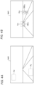
- FIGS. 4A and 4B are views showing an example of a determination region A.
- the determination region A may be fixed at a predetermined position within a frame.
- the predetermined position may be set as a range where the same object is always captured, or where nothing is captured.
- a part Ax on an upper side of an image corresponds to an empty space (sky), so a possibility that a car or a pedestrian will be captured is low. Therefore, it can be said that there are few factors that change the contrast other than the adhesion of a water droplet. Therefore, it can be said that it is suitable for the determination region.
- a part Ay on a lower side of the image corresponds to a road surface, so a possibility that a car or a pedestrian will be captured is low. Therefore, it can be said that there are few factors that change the contrast other than the adhesion of a water droplet. Therefore, it can be said that it is suitable for the determination region.
- FIG. 4B shows a dynamically changing determination region Az.
- the arithmetic processing device 440 may detect objects OBJ 1 and OBJ 2 included in a frame and determine determination region Az 1 and Az 2 so that the detected objects OBJ 1 and OBJ 2 are included. This allows a water droplet to be detected for a range where an object of interest, such as a person and a vehicle, is captured. In addition, since the change in contrast due to the presence or absence of a water droplet is greater in a part where a person, a vehicle, or the like captured, the effect of increasing the detection accuracy of water droplet can be expected.
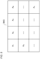
- FIG. 5 is a view showing another example of the determination region A.
- the arithmetic processing device 440 divides the image data IMG (frame) into a plurality of regions, and sets each of the divided regions as determination regions A 1 to A n .
- the arithmetic processing device 440 performs determination for each of the plurality of determination regions A 1 to A n . For example, when a decrease in contrast is detected in a plurality of regions exceeding a predetermined number, it may be finally determined that a water droplet is adhering.
- sensing system 400 A A specific example of the sensing system 400 A will be described.
- One of suitable applications of the sensing system 400 is a ToF camera.
- FIG. 6 is a block diagram of a ToF camera 400B.
- the ToF camera 400B divides a field of view into a plurality of N ranges RNG 1 to RNGrr (N ⁇ 2) with respect to a depth direction, and performs imaging.
- the ToF camera 400B includes an illumination device 410, an image sensor 420, a camera controller 430, and an arithmetic processing device 440.
- the illumination device 410 irradiates the front of the vehicle with pulsed illumination light L1 in synchronization with a light emission timing signal S1 provided from the camera controller 430.
- the illumination light L1 is preferably infrared light, but is not limited thereto, and may be visible light having a predetermined wavelength.
- the image sensor 420 is configured to be able to perform exposure control in synchronization with an imaging timing signal S2 provided from the camera controller 430 and to generate a range image IMG.
- the image sensor 420 has sensitivity to the same wavelength as the illumination light L1 and captures reflected light (return light) L2 reflected by an object OBJ.
- FIG. 7 is a view illustrating an operation of the ToF camera 400B.
- FIG. 7 shows an aspect when measuring the i-th range RNG i .
- the illumination device 410 emits light during a light emission period ⁇ 1 between time to and time t 1 in synchronization with the light emission timing signal S1.
- a diagram of a light beam where a time is indicated on the horizontal axis and a distance is indicated on the vertical axis is shown.
- a distance from the ToF camera 400B to a front side boundary of the range RNG i is set to d MINi and a distance from the ToF camera to a deep side boundary of the range RNG i is set to d MAXi .
- the light emission and the exposure are repeatedly performed multiple times, and measurement results are integrated by the image sensor 420.
- FIGS. 8A and 8B are views illustrating images obtained by the ToF camera 400B.
- an object (pedestrian) OBJ 1 is present in the range RNG 1 and an object (vehicle) OBJ 3 is present in the range RNG 3 .
- FIG. 8B shows a plurality of range images IMG 1 to IMG 3 obtained in the situation of FIG. 8A .
- an object image OBJ 1 of the pedestrian OBJ 1 appears in the range image IMG 1 because the image sensor is exposed only to reflected light from the range RNG 1 .
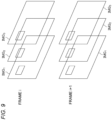
- FIG. 9 is a diagram illustrating detection of a water droplet based on range images.
- the arithmetic processing device 440 compares and refers to the determination regions of each of the plurality of range images IMG 1 to IMG N of a frame and the determination regions of each of the plurality of range images IMG 1 to IMG N of a subsequent frame. When a decrease in contrast in the determination region is detected in two or more of the plurality of range images IMG 1 to IMG N , it is determined that a water droplet has adhered.
- FIG. 10 is a view showing a sensing system provided with a water droplet removal device.
- the sensing system 400 includes a water droplet removal device 460.
- the water droplet removal device 460 is a blower type, and removes water droplets by blowing wind onto the cover glass 422.
- the water droplet removal device 460 includes a blower 462 and a duct 464. Note that the blower 462 may be arranged such that an air flow generated by the blower is directly blown onto the cover glass 422.
- the arithmetic processing device 440 When the arithmetic processing device 440 detects a water droplet through image processing, the arithmetic processing device outputs a trigger TRIG to the water droplet removal device 460. In response to the trigger TRIG, the water droplet removal device 460 blows wind onto the cover glass 422. Note that the configuration of the water droplet removal device 460 is not limited to the blower type and may also be other means such as a wiper.
- the sensing system 400 is attached to a lower side of a main body of a headlamp 600, but the camera of the sensing system 400 may be built in the headlamp 600. In this case, water droplets adhering to the cover glass 602 of the headlamp 600 are subject to detection by the sensing system 400.
- a part of the sensing system 400 for example, the image sensor or the arithmetic processing device 440 may be installed outside the vehicle lamp 200, for example, behind a room mirror.
- FIG. 12 is a block diagram showing a vehicle lamp 200 including the sensing system 400.
- the vehicle lamp 200 configures a lamp system 310 together with a vehicle-side ECU 304.
- the vehicle lamp 200 includes a light source 202, a lighting circuit 204, and an optical system 206.
- the arithmetic processing device 40 is configured to be able to identify a type of object based on an image obtained by the sensing system 400.
- the arithmetic processing device 40 may be implemented by a combination of a processor (hardware) such as a central processing unit (CPU), a micro processing unit (MPU) and a microcomputer and a software program executed by the processor (hardware).
- a processor such as a central processing unit (CPU), a micro processing unit (MPU) and a microcomputer and a software program executed by the processor (hardware).
- the arithmetic processing device 40 may be a combination of a plurality of processors. Alternatively, the arithmetic processing device 40 may be configured by only hardware.
- Information about the object OBJ detected by the arithmetic processing device 40 may be used for light distribution control of the vehicle lamp 200.
- a lamp-side ECU 208 generates a proper light distribution pattern on the basis of information about a type and a position of the object OBJ generated by the arithmetic processing device 40.
- the lighting circuit 204 and the optical system 206 operate so that the light distribution pattern generated by the lamp-side ECU 208 is obtained.
- the information about the object OBJ detected by the arithmetic processing device 40 may be transmitted to the vehicle-side ECU 304.
- the vehicle-side ECU may perform automatic driving on the basis of the information.
- the sensing system 400 is not limited to the ToF camera, and may be a light detection and ranging, laser imaging detection and ranging (LiDAR). Alternatively, the sensing system 400 may be a single pixel imaging device (quantum radar) using correlation calculation.
- a decrease in contrast is detected through a change in the histogram, but the means for determining the decrease in contrast is not limited thereto.
- the arithmetic processing device 440 may determine that a water droplet has adhered when a spatial frequency of a determination region of a frame decreases from a spatial frequency of a determination region of a previous frame.
- a part of the image data is set as the determination region, but the entire image data may be set as the determination region.
- the present disclosure relates to a sensing system for an automobile.
- OBJ object
- S1 light emission timing signal
- S2 imaging timing signal
- 200 vehicle lamp
- 202 light source
- 204 lighting circuit
- 206 optical system
- 310 lamp system
- 304 vehicle-side ECU
- 400 sensing system
- 410 illumination device
- 420 image sensor
- 430 sensing controller
- 440 arithmetic processing device
- 460 water droplet removal device.
Landscapes
- Engineering & Computer Science (AREA)
- Physics & Mathematics (AREA)
- General Physics & Mathematics (AREA)
- Multimedia (AREA)
- Theoretical Computer Science (AREA)
- Computer Vision & Pattern Recognition (AREA)
- Software Systems (AREA)
- Signal Processing (AREA)
- Computer Networks & Wireless Communication (AREA)
- Radar, Positioning & Navigation (AREA)
- Remote Sensing (AREA)
- Investigating Or Analysing Materials By Optical Means (AREA)
Abstract
Description
- The present disclosure relates to a sensing system for an automobile.
- An object identification system that senses a position and a type of an object around a vehicle is used for automatic driving or automatic control of a light distribution of a headlamp. The object identification system includes a sensor and an arithmetic processing device that analyzes an output of the sensor. The sensor is selected from a camera, a light detection and ranging or laser imaging detection and ranging (LiDAR), a millimeter-wave radar, an ultrasonic sonar, and the like, considering use, required accuracy, and cost.
- Optical sensors (hereinafter, simply referred to as sensors) are largely divided into passive sensors and active sensors. The passive sensor detects light emitted by an object or light reflected by an object from environmental light, and the sensor itself does not emit light. On the other hand, the active sensor irradiates an object with illumination light and detects reflected light thereof. The active sensor mainly includes a light projector (illuminator) that irradiates an object with light and a light sensor that detects reflected light from the object. The active sensor has an advantage of being able to increase resistance to disturbances over the passive sensor by matching a wavelength of the illumination light and a sensitivity wavelength range of the sensor.
- When water droplets adhere to a cover glass surface of an image sensor, detection accuracy deteriorates. For this reason, in a sensing system that needs to secure detection accuracy even in bad weather, measures such as adding a water droplet removal mechanism such as a wiper are required. In this case, it is necessary to detect adhesion of water droplets in order to properly give a trigger for activating a raindrop removal operation to the water droplet removal mechanism.
- A raindrop sensor is known as a technology for detecting water droplets, but adding a raindrop sensor to the sensing system increases cost. In addition, the raindrop sensor cannot be attached on an optical axis of the image sensor because it interferes with sensing.
- Further, even when no water droplet removal mechanism is provided, detection of water droplets is desirable from a standpoint of functional safety because it allows prediction of a deterioration in the accuracy of the sensing system.
- The present disclosure has been made in view of such problems, and one of the exemplary purposes thereof is to provide a sensing system that can detect raindrops by image processing.
- A sensing system of one aspect of the present disclosure includes an image sensor and an arithmetic processing device configured to process an image generated by the image sensor. The arithmetic processing device is configured to determine presence or absence of a water droplet based on a change in the same determination region of two consecutive frames of the image.
- Note that optional combinations of the constituent elements described above and mutual substitutions of constituent elements or expressions among methods, apparatuses, systems, or the like are also valid as aspects of the present invention or present disclosure. Furthermore, the description of this item (SUMMARY OF INVENTION) does not describe all the indispensable features of the present invention, and therefore, the sub-combinations of these features described can also be the present invention.
- According to one aspect of the present disclosure, it is possible to detect a water droplet.
-
-
FIG. 1 is a block diagram of a sensing system according to an embodiment. -
FIG. 2 is a view illustrating an effect of a water droplet on image data. -
FIGS. 3A and 3B are views illustrating detection of a water droplet by the sensing system ofFIG. 1 . -
FIGS. 4A and 4B are views showing an example of a determination region A. -
FIG. 5 is a view showing another example of the determination region A. -
FIG. 6 is a block diagram of a sensing system. -
FIG. 7 is a view illustrating an operation of the ToF camera. -
FIGS. 8A and 8B are views illustrating images obtained by the ToF camera. -
FIG. 9 is a view illustrating detection of a water droplet based on range images. -
FIG. 10 is a view showing a sensing system provided with a water droplet removal device. -
FIG. 11 is a view showing a vehicle lamp with a built-in sensing system. -
FIG. 12 is a block diagram showing a vehicle lamp including a sensing system. - An outline of several exemplary embodiments of the present disclosure will be described. The outline is a simplified explanation regarding several concepts of one or multiple embodiments as an introduction to the detailed description described below in order to provide a basic understanding of the embodiments, and is by no means intended to limit the scope of the present invention or disclosure. Furthermore, the outline is by no means a comprehensive outline of all conceivable embodiments, and does not limit the essential components of the embodiments. For convenience, in some cases, "one embodiment" as used herein refers to a single embodiment (embodiment or modified variation) or a plurality of embodiments (embodiments or variations) disclosed in the present specification.
- A sensing system according to one embodiment includes an image sensor and an arithmetic processing device configured to process an image generated by the image sensor. The arithmetic processing device is configured to determine presence or absence of a water droplet based on a change in the same determination region of two consecutive frames of the image.
- The present inventor has recognized that when water droplets adhere to a cover glass on an optical axis of an image sensor (on a field of view), the contrast of an image decreases due to scattering by the water droplets. When comparing two temporally adjacent frames, it is rare for positions of the same object appearing in an image to be significantly different, and it is rare for the brightness of the object to be significantly different. Therefore, when the same determination region in two frames is compared, the contrast is likely to be substantially the same. In other words, if a significant decrease in contrast is detected in the same determination region, it can be assumed that the decrease is due to the adhesion of water droplets. As such, according to the above configuration, the adhesion of water droplets can be determined by image processing.
- To determine whether the "contrast has decreased," a determination value serving as an index of contrast may be generated for the determination region of each frame and the determination may be made based on a relative relationship or absolute relationship between the two determination values.
- In one embodiment, the determination region may be set at a predetermined position. The predetermined position may be set as a range where the same object is always captured, or where nothing is captured. Such a location can be said to be suitable for the determination region because it can be said that there are few factors that cause a change in the contrast other than the adhesion of water droplets. For example, an upper part of an image corresponds to a blank space (sky), and a lower part of the image corresponds to a road surface. By setting a region where the same subject is always captured as the determination region, it becomes easy to detect the contrast caused by the adhesion of water droplets.
- In one embodiment, the arithmetic processing device may be configured to divide each of the two consecutive frames into a plurality of determination regions and to determine adhesion of a water droplet for each determination region.
- In one embodiment, the arithmetic processing device may be configured to detect an object included in an image and to set the determination region so that the object which is detected is included. This allows a water droplet to be detected for a range where an object of interest, such as a person and a vehicle, is captured. In addition, since the change in contrast due to the presence or absence of a water droplet is greater in a part where a person, a vehicle, or the like captured, the effect of increasing the detection accuracy of water droplet can be expected.
- In one embodiment, the arithmetic processing device may be configured to generate two histograms for the determination regions of the two frames. By generating the histograms, the change in contrast can be detected.
- In one embodiment, the arithmetic processing device may determine that a water droplet has adhered when a frequency of a predetermined section on a low-brightness side of a histogram of a frame decreases from a frequency of the same section of a histogram of a previous frame. When a water droplet adheres, a pixel value of a part where no object is present increases due to scattered light caused by the water droplet. Therefore, the water droplet can be detected based on the frequency of the section on the low-brightness side.
- In one embodiment, the arithmetic processing device may determine that a water droplet has adhered when a median value of a predetermined section of a histogram of a frame increases more than a median value of a predetermined section of a histogram of a previous frame. When a water droplet adheres, a pixel value of a part where no object is present increases due to scattered light caused by the water droplet, whereby the median value is shifted to the high-brightness side. For this reason, the water droplet can be detected based on the change in the median value of the histogram.
- In one embodiment, the arithmetic processing device may determine that a water droplet has adhered when a spatial frequency of a determination region of a frame decreases from a spatial frequency of a determination region of a previous frame. When scattering occurs due to a water droplet, an outline of an image of an object becomes blurred and the contrast decreases. The blurring of the outline appears as a result of a decrease in spatial frequency. Therefore, by monitoring the spatial frequency, the adhesion of water droplet can be detected.
- In one embodiment, an illumination device configured to irradiate a field of view with illumination light may be additionally provided. The sensing system may be a time of flight (ToF) camera configured to divide a field of view into a plurality of ranges with respect to a depth direction and to change a time difference between light emission and imaging for each range, making it possible to obtain a plurality of range images corresponding to the plurality of ranges.
- In one embodiment, the arithmetic processing device may be configured to compare a determination region of each of the plurality of range images of a frame with a determination region of each of the plurality of range images of a subsequent frame, and determine that a water droplet has adhered when a decrease in contrast is detected in two or more range images. The effect of water droplet appears in the plurality of range images corresponding to the plurality of ranges. Therefore, detection accuracy can be increased by setting detection of a decrease in contrast in two or more range images as a condition for the determination of a water droplet.
- Hereinafter, favorable embodiments will be described with reference to the drawings. The same or equivalent components, members and processing shown in each drawing are denoted with the same reference numerals, and repeated descriptions will be omitted appropriately. Furthermore, the embodiments are illustrative, not limiting the disclosure, and all features or combinations thereof described in the embodiments are not necessarily essential to the invention.
-
FIG. 1 is a block diagram of asensing system 400 according to an embodiment. Thesensing system 400 includes a visible light camera, an infrared camera, a stereo camera, a ToF camera, a LIDAR, or the like. In the present embodiment, thesensing system 400 is an active sensor, and includes anillumination device 410, animage sensor 420, asensing controller 430, and anarithmetic processing device 440. - The
illumination device 410 includes a semiconductor light-emitting element such as a laser diode or a light-emitting diode (LED), and irradiates a field of view with illumination light L1. A wavelength of the illumination light L1 is not particularly limited, and the illumination light may be infrared light, visible light, or white light. - The
image sensor 420 has sensitivity to the same wavelength as the illumination light L1. Thelight sensor 420 receives reflected light L2 by an object OBJ within a sensing range (field of view) of thesensing system 400 from the illumination light L1 and generates image data IMG. - The
sensing controller 430 integrally controls thesensing system 400. Specifically, light emission from the illumination device 110 and sensing by theimage sensor 420 are synchronously controlled. - The
arithmetic processing device 440 processes the image data IMG generated by theimage sensor 420. - A
cover glass 422 is provided on an optical axis of theimage sensor 420. Thecover glass 422 is a member directly exposed to an external environment and may be a part of theimage sensor 420 or a separate member independent from theimage sensor 420. - The
arithmetic processing device 440 has a function of processing the image data IMG to detect a water droplet WD adhering to thecover glass 422. - When the
arithmetic processing device 440 detects a decrease in contrast in the same region (referred to as a determination region) of two temporally consecutive frames Fi and Fi+1 of the image data IMG, the arithmetic processing device determines that the water droplet WD is adhering. - The above is the configuration of the
sensing system 400. Subsequently, operations thereof will be described.FIG. 2 is a view illustrating an effect of water droplets on image data.FIG. 2 shows image data of two pieces obtained by capturing the same scene. On the left is image data before a water droplet adheres, and on the right is image data after a water droplet adheres. When a water droplet adheres, reflected light from an object or light emitted by the object is scattered by the water droplet, so the brightness of a part where no object is present becomes brighter. That is, the water droplet lowers the contrast of an image compared to a case where no water droplet is present. - In addition, when a water droplet adheres, an outline of an object becomes faintly visible. That is, when focusing on a narrow region including an object, the water droplet lowers the contrast of an image compared to a case where no water droplet is present.
-
FIGS.3A and 3B are views illustrating detection of a water droplet by thesensing system 400 ofFIG. 1 .FIG. 3A shows two temporally consecutive frames Fi and Fi+1. In the respective frames Fi and Fi+1, determination regions Ai and Ai+1 of the same size and same position are shown. It is assumed that no water droplet adheres in the determination region Ai of the preceding frame Fi and a water droplet WD adheres in the determination region Ai+1 of the subsequent frame Fi+1. Note that since the water drop WD is transparent, the water drop WD is not captured in an image itself. - In
FIG. 3B , histograms of the determination regions Ai and Ai+1 of the two frames Fi and Fi+1 are shown, respectively. - The
arithmetic processing device 440 generates two histograms HISTi, and HISTi+1 for the determination regions Ai and Ai+1 of the two frames Fi and Fi+1. When light is scattered by a water droplet, light incident on pixels that were originally receiving strong light decreases, and light incident on pixels that were not originally receiving light increases. As a result, the histogram shows a decrease in frequency of a low-gradation section (dark part) DARK with a small brightness value and an increase in frequency of a high-gradation section (bright part) BRIGHT with a large brightness value or an intermediate-gradation section. This results in a transition to a frequency distribution that is flat or is biased toward the high-brightness and a decrease in contrast. - The
arithmetic processing device 440 determines the presence or absence of the water droplet WD by detecting a change in the histogram, that is, a decrease in contrast. - For example, the
arithmetic processing device 440 may monitor the histogram of the low-gradation section DARK and detect the adhesion of a water droplet based on a change of the histogram. - For example, a plurality of adjacent bins in the low-gradation section DARK, for example, three adjacent bins, are set as a monitoring section, and the adhesion of a water droplet is detected by comparing sums of frequencies in the monitoring sections. For example, when a difference between a sum of frequencies in the monitoring section of the histogram HISTi+1 and a sum of frequencies in the monitoring section of the histogram HISTi exceeds a threshold, it may be determined that a water droplet has adhered.
- Alternatively, the
arithmetic processing device 440 may detect the adhesion of a water droplet by comparing the median values of the monitoring sections. - The presence or absence of a water droplet may also be determined based on the high-gradation section BRIGHT rather than the low-gradation section DARK. For example, a plurality of adjacent bins in the high-gradation section BRIGHT are set as a monitoring section, and the adhesion of a water droplet is detected by comparing sums of frequencies in the monitoring sections. For example, when a difference between a sum of frequencies in the monitoring section of the histogram HISTi+1 and a sum of frequencies in the monitoring section of the histogram HISTi exceeds a threshold, it may be determined that a water droplet has adhered. Alternatively, the
arithmetic processing device 440 may detect the adhesion of a water droplet by comparing the median values in the monitoring sections. - Next, a determination region A will be described.
FIGS. 4A and 4B are views showing an example of a determination region A. - As shown in
FIG. 4A , the determination region A may be fixed at a predetermined position within a frame. The predetermined position may be set as a range where the same object is always captured, or where nothing is captured. For example, a part Ax on an upper side of an image corresponds to an empty space (sky), so a possibility that a car or a pedestrian will be captured is low. Therefore, it can be said that there are few factors that change the contrast other than the adhesion of a water droplet. Therefore, it can be said that it is suitable for the determination region. - In addition, a part Ay on a lower side of the image corresponds to a road surface, so a possibility that a car or a pedestrian will be captured is low. Therefore, it can be said that there are few factors that change the contrast other than the adhesion of a water droplet. Therefore, it can be said that it is suitable for the determination region.
- As such, by setting a range where the same subject is always captured as the determination region, it becomes easy to detect the contrast caused by the adhesion of a water droplet.
- Conversely, the determination region A may be changed dynamically.
FIG. 4B shows a dynamically changing determination region Az. Thearithmetic processing device 440 may detect objects OBJ1 and OBJ2 included in a frame and determine determination region Az1 and Az2 so that the detected objects OBJ1 and OBJ2 are included. This allows a water droplet to be detected for a range where an object of interest, such as a person and a vehicle, is captured. In addition, since the change in contrast due to the presence or absence of a water droplet is greater in a part where a person, a vehicle, or the like captured, the effect of increasing the detection accuracy of water droplet can be expected. -
FIG. 5 is a view showing another example of the determination region A. Thearithmetic processing device 440 divides the image data IMG (frame) into a plurality of regions, and sets each of the divided regions as determination regions A1 to An. Thearithmetic processing device 440 performs determination for each of the plurality of determination regions A1 to An. For example, when a decrease in contrast is detected in a plurality of regions exceeding a predetermined number, it may be finally determined that a water droplet is adhering. - A specific example of the sensing system 400 A will be described. One of suitable applications of the
sensing system 400 is a ToF camera. -
FIG. 6 is a block diagram of aToF camera 400B. TheToF camera 400B divides a field of view into a plurality of N ranges RNG1 to RNGrr (N≥2) with respect to a depth direction, and performs imaging. - The
ToF camera 400B includes anillumination device 410, animage sensor 420, acamera controller 430, and anarithmetic processing device 440. - The
illumination device 410 irradiates the front of the vehicle with pulsed illumination light L1 in synchronization with a light emission timing signal S1 provided from thecamera controller 430. The illumination light L1 is preferably infrared light, but is not limited thereto, and may be visible light having a predetermined wavelength. - The
image sensor 420 is configured to be able to perform exposure control in synchronization with an imaging timing signal S2 provided from thecamera controller 430 and to generate a range image IMG. Theimage sensor 420 has sensitivity to the same wavelength as the illumination light L1 and captures reflected light (return light) L2 reflected by an object OBJ. - The
camera controller 430 maintains predetermined light emission timing and exposure timing for each range RNG. When imaging any range RNGi, thecamera controller 430 generates a light emission timing signal S1 and an imaging timing signal S2 on the basis of the light emission timing and exposure timing corresponding to the range and performs the imaging. TheToF camera 400B can generate a plurality of range images IMG1 to IMGN corresponding to the plurality of ranges RNG1 to RNGN. In an i-th range image IMGi, an object included in the corresponding range RNGi appears. -
FIG. 7 is a view illustrating an operation of theToF camera 400B.FIG. 7 shows an aspect when measuring the i-th range RNGi. Theillumination device 410 emits light during a light emission period τ1 between time to and time t1 in synchronization with the light emission timing signal S1. At the top, a diagram of a light beam where a time is indicated on the horizontal axis and a distance is indicated on the vertical axis is shown. A distance from theToF camera 400B to a front side boundary of the range RNGi is set to dMINi and a distance from the ToF camera to a deep side boundary of the range RNGi is set to dMAXi. - Round-trip time TMINi from when light emitted from the
illumination device 410 at a certain time point reaches the distance dMINi to when reflected light returns to theimage sensor 420 is expressed as
- Similarly, round-trip time TMAXi from when light emitted from the
illumination device 410 at a certain time point reaches the distance dMAXi to when reflected light returns to theimage sensor 420 is expressed as TMAXi=2×dMAXi/c. - When it is desired to image the object OBJ included in the range RNGi, the
camera controller 430 generates the imaging timing signal S2 so that the exposure starts at a time t2=t0+TMINi and ends at a time t3=t1+TMAXi. This is one exposure operation. - When imaging the i-th range RNGi, the light emission and the exposure are repeatedly performed multiple times, and measurement results are integrated by the
image sensor 420. -
FIGS. 8A and 8B are views illustrating images obtained by theToF camera 400B. In an example ofFIG. 8A , an object (pedestrian) OBJ1 is present in the range RNG1 and an object (vehicle) OBJ3 is present in the range RNG3.FIG. 8B shows a plurality of range images IMG1 to IMG3 obtained in the situation ofFIG. 8A . When capturing the range image IMG1, an object image OBJ1 of the pedestrian OBJ1 appears in the range image IMG1 because the image sensor is exposed only to reflected light from the range RNG1. - When capturing the range image IMG2, no object image appears in the range image IMG2 because the image sensor is exposed to reflected light from the range RNG2.
- Similarly, when capturing the range image IMG3, only the object image OBJ3 appears in the range image IMG3 because the image sensor is exposed to reflected light from the range RNG3. In this way, an object can be separately captured for each range by the
ToF camera 400B. - Returning to
FIG. 6 , thearithmetic processing device 440 detects adhesion of a water droplet on the basis of the plurality of range images IMG1 to IMGN. -
FIG. 9 is a diagram illustrating detection of a water droplet based on range images. Thearithmetic processing device 440 compares and refers to the determination regions of each of the plurality of range images IMG1 to IMGN of a frame and the determination regions of each of the plurality of range images IMG1 to IMGN of a subsequent frame. When a decrease in contrast in the determination region is detected in two or more of the plurality of range images IMG1 to IMGN, it is determined that a water droplet has adhered. - It is highly likely for the effect of a water droplet to appear in multiple images of the plurality of range images IMG1 to IMGN, not a range image of a specific range. Therefore, detection accuracy can be increased by setting detection of a decrease in contrast in two or more range images as a condition for the determination of a water droplet.
- The detection result by the
arithmetic processing device 440 can be used as a trigger for starting an operation of a water droplet removal device. -
FIG. 10 is a view showing a sensing system provided with a water droplet removal device. Thesensing system 400 includes a waterdroplet removal device 460. The waterdroplet removal device 460 is a blower type, and removes water droplets by blowing wind onto thecover glass 422. The waterdroplet removal device 460 includes ablower 462 and aduct 464. Note that theblower 462 may be arranged such that an air flow generated by the blower is directly blown onto thecover glass 422. - When the
arithmetic processing device 440 detects a water droplet through image processing, the arithmetic processing device outputs a trigger TRIG to the waterdroplet removal device 460. In response to the trigger TRIG, the waterdroplet removal device 460 blows wind onto thecover glass 422. Note that the configuration of the waterdroplet removal device 460 is not limited to the blower type and may also be other means such as a wiper. - In
FIG. 10 , thesensing system 400 is attached to a lower side of a main body of aheadlamp 600, but the camera of thesensing system 400 may be built in theheadlamp 600. In this case, water droplets adhering to thecover glass 602 of theheadlamp 600 are subject to detection by thesensing system 400. -
FIG. 11 is a view showing avehicle lamp 200 with a built-insensing system 400. Thevehicle lamp 200 includes ahousing 210, anouter lens 220, lamp units 230H/230L for high beam and low beam, and asensing system 400. The lamp units 230H/230L and thesensing system 400 are accommodated in thehousing 210. - Note that a part of the
sensing system 400, for example, the image sensor or thearithmetic processing device 440 may be installed outside thevehicle lamp 200, for example, behind a room mirror. -
FIG. 12 is a block diagram showing avehicle lamp 200 including thesensing system 400. Thevehicle lamp 200 configures alamp system 310 together with a vehicle-side ECU 304. Thevehicle lamp 200 includes alight source 202, alighting circuit 204, and anoptical system 206. - The
arithmetic processing device 40 is configured to be able to identify a type of object based on an image obtained by thesensing system 400. - The
arithmetic processing device 40 may be implemented by a combination of a processor (hardware) such as a central processing unit (CPU), a micro processing unit (MPU) and a microcomputer and a software program executed by the processor (hardware). Thearithmetic processing device 40 may be a combination of a plurality of processors. Alternatively, thearithmetic processing device 40 may be configured by only hardware. - Information about the object OBJ detected by the
arithmetic processing device 40 may be used for light distribution control of thevehicle lamp 200. Specifically, a lamp-side ECU 208 generates a proper light distribution pattern on the basis of information about a type and a position of the object OBJ generated by thearithmetic processing device 40. Thelighting circuit 204 and theoptical system 206 operate so that the light distribution pattern generated by the lamp-side ECU 208 is obtained. - Furthermore, the information about the object OBJ detected by the
arithmetic processing device 40 may be transmitted to the vehicle-side ECU 304. The vehicle-side ECU may perform automatic driving on the basis of the information. - It is understood by one skilled in the art that the above-described embodiments are illustrative and various variations can be made to combinations of each component or each processing process. In the below, such variations will be described.
- The
sensing system 400 is not limited to the ToF camera, and may be a light detection and ranging, laser imaging detection and ranging (LiDAR). Alternatively, thesensing system 400 may be a single pixel imaging device (quantum radar) using correlation calculation. - In the embodiment, a decrease in contrast is detected through a change in the histogram, but the means for determining the decrease in contrast is not limited thereto. The
arithmetic processing device 440 may determine that a water droplet has adhered when a spatial frequency of a determination region of a frame decreases from a spatial frequency of a determination region of a previous frame. - In the embodiment, a part of the image data is set as the determination region, but the entire image data may be set as the determination region.
- It should be understood by one skilled in the art that the embodiments are merely illustrative, various variations can be made to combinations of components and processing processes in the embodiments and such variations also fall within the scope of the present invention.
- The present disclosure relates to a sensing system for an automobile.
- OBJ: object, S1: light emission timing signal, S2: imaging timing signal, 200: vehicle lamp, 202: light source, 204: lighting circuit, 206: optical system, 310: lamp system, 304: vehicle-side ECU, 400: sensing system, 410: illumination device, 420: image sensor, 430: sensing controller, 440: arithmetic processing device, 460: water droplet removal device.
Claims (10)
- A sensing system comprising:an image sensor; andan arithmetic processing device configured to process an image generated by the image sensor;wherein the arithmetic processing device is configured to determine presence or absence of a water droplet based on a change in the same determination region of two consecutive frames of the image.
- The sensing system according to claim 1, wherein the determination region is set at a predetermined position.
- The sensing system according to claim 1 or 2, wherein the arithmetic processing device is configured to divide each of the two consecutive frames into a plurality of determination regions and to determine adhesion of a water droplet for each determination region.
- The sensing system according to claim 1, wherein the arithmetic processing device is configured to detect an object included in the image and to set the determination region so that the object which is detected is included.
- The sensing system according to any one of claims 1 to 4, wherein the arithmetic processing device is configured to generate two histograms for the determination regions of the two frames.
- The sensing system according to claim 5, wherein the arithmetic processing device determines that a water droplet has adhered when a frequency of a predetermined section on a low-brightness side of a histogram of a frame decreases from a frequency of the same section of a histogram of a previous frame.
- The sensing system according to claim 5, wherein the arithmetic processing device determines that a water droplet has adhered when a median value of a predetermined section of a histogram of a frame increases more than a median value of a predetermined section of a histogram of a previous frame.
- The sensing system according to any one of claims 1 to 4, wherein the arithmetic processing device determines that a water droplet has adhered when a spatial frequency of a determination region of a frame decreases from a spatial frequency of a determination region of a previous frame.
- The sensing system according to any one of claims 1 to 8, further comprising an illumination device configured to irradiate a field of view with illumination light,
wherein the sensing system is a time of flight (ToF) camera configured to divide a field of view into a plurality of ranges with respect to a depth direction and to change a time difference between light emission and imaging for each range, making it possible to obtain a plurality of range images corresponding to the plurality of ranges. - The sensing system according to claim 9, wherein the arithmetic processing device is configured to compare a determination region of each of the plurality of range images of a frame with a determination region of each of the plurality of range images of a subsequent frame, and to determine that a water droplet has adhered when a decrease in contrast is detected in two or more range images.
Applications Claiming Priority (2)
| Application Number | Priority Date | Filing Date | Title |
|---|---|---|---|
| JP2021185116 | 2021-11-12 | ||
| PCT/JP2022/042113 WO2023085403A1 (en) | 2021-11-12 | 2022-11-11 | Sensing system |
Publications (2)
| Publication Number | Publication Date |
|---|---|
| EP4432681A1 true EP4432681A1 (en) | 2024-09-18 |
| EP4432681A4 EP4432681A4 (en) | 2025-03-05 |
Family
ID=86335868
Family Applications (1)
| Application Number | Title | Priority Date | Filing Date |
|---|---|---|---|
| EP22892901.4A Pending EP4432681A4 (en) | 2021-11-12 | 2022-11-11 | SENSOR SYSTEM |
Country Status (5)
| Country | Link |
|---|---|
| US (1) | US20250061723A1 (en) |
| EP (1) | EP4432681A4 (en) |
| JP (1) | JPWO2023085403A1 (en) |
| CN (1) | CN118235419A (en) |
| WO (1) | WO2023085403A1 (en) |
Family Cites Families (5)
| Publication number | Priority date | Publication date | Assignee | Title |
|---|---|---|---|---|
| JP2005005799A (en) * | 2003-06-09 | 2005-01-06 | Mitsubishi Electric Corp | Moving target identification device |
| JP2007159021A (en) * | 2005-12-08 | 2007-06-21 | Matsushita Electric Ind Co Ltd | Camera device and wiper control method |
| JP2018032984A (en) * | 2016-08-24 | 2018-03-01 | ソニー株式会社 | Image processing apparatus, imaging apparatus, and image processing method and program |
| JP6755161B2 (en) * | 2016-10-24 | 2020-09-16 | 株式会社デンソーテン | Adhesion detection device and deposit detection method |
| US10552706B2 (en) * | 2016-10-24 | 2020-02-04 | Fujitsu Ten Limited | Attachable matter detection apparatus and attachable matter detection method |
-
2022
- 2022-11-11 WO PCT/JP2022/042113 patent/WO2023085403A1/en not_active Ceased
- 2022-11-11 EP EP22892901.4A patent/EP4432681A4/en active Pending
- 2022-11-11 US US18/709,428 patent/US20250061723A1/en active Pending
- 2022-11-11 JP JP2023559928A patent/JPWO2023085403A1/ja active Pending
- 2022-11-11 CN CN202280074628.9A patent/CN118235419A/en active Pending
Also Published As
| Publication number | Publication date |
|---|---|
| US20250061723A1 (en) | 2025-02-20 |
| CN118235419A (en) | 2024-06-21 |
| EP4432681A4 (en) | 2025-03-05 |
| JPWO2023085403A1 (en) | 2023-05-19 |
| WO2023085403A1 (en) | 2023-05-19 |
Similar Documents
| Publication | Publication Date | Title |
|---|---|---|
| US12262101B2 (en) | Gating camera | |
| US12135394B2 (en) | Gating camera | |
| US11961306B2 (en) | Object detection device | |
| US20170259728A1 (en) | Vehicle lighting system | |
| JP6782433B2 (en) | Image recognition device | |
| EP4202502B1 (en) | In-vehicle sensing systems and gating camera | |
| JP2010512271A (en) | Identification of vehicle lights by camera | |
| US20230341749A1 (en) | Gating camera, vehicle sensing system, and vehicle lamp | |
| US20250061723A1 (en) | Sensing system | |
| EP4428570A1 (en) | Sensing system and automobile | |
| US20240067094A1 (en) | Gating camera, vehicle sensing system, and vehicle lamp | |
| US12289515B2 (en) | Vehicle-mounted sensing system and gated camera | |
| EP4428569A1 (en) | Active sensor, object identification system, and vehicular lamp | |
| US20230311897A1 (en) | Automotive sensing system and gating camera | |
| CN116648664A (en) | Automotive sensor systems and door control cameras | |
| EP4382968A1 (en) | Gating camera, vehicular sensing system, and vehicular lamp | |
| JP7656584B2 (en) | Sensor, vehicle and surrounding environment sensing method | |
| EP4528330A1 (en) | Tof camera, vehicular sensing system, and vehicle lamp fitting | |
| CN111835946B (en) | Vision Systems and Object Detection Methods | |
| JP2024007678A (en) | Image processing device and image processing method |
Legal Events
| Date | Code | Title | Description |
|---|---|---|---|
| STAA | Information on the status of an ep patent application or granted ep patent |
Free format text: STATUS: THE INTERNATIONAL PUBLICATION HAS BEEN MADE |
|
| PUAI | Public reference made under article 153(3) epc to a published international application that has entered the european phase |
Free format text: ORIGINAL CODE: 0009012 |
|
| STAA | Information on the status of an ep patent application or granted ep patent |
Free format text: STATUS: REQUEST FOR EXAMINATION WAS MADE |
|
| 17P | Request for examination filed |
Effective date: 20240510 |
|
| AK | Designated contracting states |
Kind code of ref document: A1 Designated state(s): AL AT BE BG CH CY CZ DE DK EE ES FI FR GB GR HR HU IE IS IT LI LT LU LV MC ME MK MT NL NO PL PT RO RS SE SI SK SM TR |
|
| RIN1 | Information on inventor provided before grant (corrected) |
Inventor name: TOKIDA, MASANORI |
|
| DAV | Request for validation of the european patent (deleted) | ||
| DAX | Request for extension of the european patent (deleted) | ||
| A4 | Supplementary search report drawn up and despatched |
Effective date: 20250131 |
|
| RIC1 | Information provided on ipc code assigned before grant |
Ipc: H04N 23/81 20230101ALI20250127BHEP Ipc: G06V 10/60 20220101ALI20250127BHEP Ipc: G06V 10/50 20220101ALI20250127BHEP Ipc: G06T 7/194 20170101ALI20250127BHEP Ipc: G06T 7/174 20170101ALI20250127BHEP Ipc: G06V 20/56 20220101ALI20250127BHEP Ipc: G06V 10/62 20220101ALI20250127BHEP Ipc: H04N 23/60 20230101ALI20250127BHEP Ipc: G06T 7/00 20170101ALI20250127BHEP Ipc: G01S 7/497 20060101ALI20250127BHEP Ipc: H04N 23/52 20230101AFI20250127BHEP |
|
| STAA | Information on the status of an ep patent application or granted ep patent |
Free format text: STATUS: EXAMINATION IS IN PROGRESS |