EP4432494A1 - Vacuum circuit breaker - Google Patents
Vacuum circuit breaker Download PDFInfo
- Publication number
- EP4432494A1 EP4432494A1 EP21964055.4A EP21964055A EP4432494A1 EP 4432494 A1 EP4432494 A1 EP 4432494A1 EP 21964055 A EP21964055 A EP 21964055A EP 4432494 A1 EP4432494 A1 EP 4432494A1
- Authority
- EP
- European Patent Office
- Prior art keywords
- movable
- contact point
- fixed
- vacuum
- gas pressure
- Prior art date
- Legal status (The legal status is an assumption and is not a legal conclusion. Google has not performed a legal analysis and makes no representation as to the accuracy of the status listed.)
- Granted
Links
Images




Classifications
-
- H—ELECTRICITY
- H02—GENERATION; CONVERSION OR DISTRIBUTION OF ELECTRIC POWER
- H02B—BOARDS, SUBSTATIONS OR SWITCHING ARRANGEMENTS FOR THE SUPPLY OR DISTRIBUTION OF ELECTRIC POWER
- H02B13/00—Arrangement of switchgear in which switches are enclosed in, or structurally associated with, a casing, e.g. cubicle
- H02B13/02—Arrangement of switchgear in which switches are enclosed in, or structurally associated with, a casing, e.g. cubicle with metal casing
- H02B13/035—Gas-insulated switchgear
-
- H—ELECTRICITY
- H01—ELECTRIC ELEMENTS
- H01H—ELECTRIC SWITCHES; RELAYS; SELECTORS; EMERGENCY PROTECTIVE DEVICES
- H01H33/00—High-tension or heavy-current switches with arc-extinguishing or arc-preventing means
- H01H33/60—Switches wherein the means for extinguishing or preventing the arc do not include separate means for obtaining or increasing flow of arc-extinguishing fluid
- H01H33/66—Vacuum switches
- H01H33/662—Housings or protective screens
- H01H33/66207—Specific housing details, e.g. sealing, soldering or brazing
-
- H—ELECTRICITY
- H01—ELECTRIC ELEMENTS
- H01H—ELECTRIC SWITCHES; RELAYS; SELECTORS; EMERGENCY PROTECTIVE DEVICES
- H01H33/00—High-tension or heavy-current switches with arc-extinguishing or arc-preventing means
- H01H33/60—Switches wherein the means for extinguishing or preventing the arc do not include separate means for obtaining or increasing flow of arc-extinguishing fluid
- H01H33/66—Vacuum switches
- H01H33/662—Housings or protective screens
-
- H—ELECTRICITY
- H01—ELECTRIC ELEMENTS
- H01H—ELECTRIC SWITCHES; RELAYS; SELECTORS; EMERGENCY PROTECTIVE DEVICES
- H01H33/00—High-tension or heavy-current switches with arc-extinguishing or arc-preventing means
- H01H33/60—Switches wherein the means for extinguishing or preventing the arc do not include separate means for obtaining or increasing flow of arc-extinguishing fluid
- H01H33/66—Vacuum switches
- H01H33/666—Operating arrangements
-
- H—ELECTRICITY
- H01—ELECTRIC ELEMENTS
- H01H—ELECTRIC SWITCHES; RELAYS; SELECTORS; EMERGENCY PROTECTIVE DEVICES
- H01H33/00—High-tension or heavy-current switches with arc-extinguishing or arc-preventing means
- H01H33/60—Switches wherein the means for extinguishing or preventing the arc do not include separate means for obtaining or increasing flow of arc-extinguishing fluid
- H01H33/66—Vacuum switches
- H01H33/666—Operating arrangements
- H01H33/6661—Combination with other type of switch, e.g. for load break switches
-
- H—ELECTRICITY
- H01—ELECTRIC ELEMENTS
- H01H—ELECTRIC SWITCHES; RELAYS; SELECTORS; EMERGENCY PROTECTIVE DEVICES
- H01H33/00—High-tension or heavy-current switches with arc-extinguishing or arc-preventing means
- H01H33/60—Switches wherein the means for extinguishing or preventing the arc do not include separate means for obtaining or increasing flow of arc-extinguishing fluid
- H01H33/66—Vacuum switches
- H01H33/666—Operating arrangements
- H01H33/6664—Operating arrangements with pivoting movable contact structure
-
- H—ELECTRICITY
- H02—GENERATION; CONVERSION OR DISTRIBUTION OF ELECTRIC POWER
- H02B—BOARDS, SUBSTATIONS OR SWITCHING ARRANGEMENTS FOR THE SUPPLY OR DISTRIBUTION OF ELECTRIC POWER
- H02B13/00—Arrangement of switchgear in which switches are enclosed in, or structurally associated with, a casing, e.g. cubicle
- H02B13/02—Arrangement of switchgear in which switches are enclosed in, or structurally associated with, a casing, e.g. cubicle with metal casing
- H02B13/035—Gas-insulated switchgear
- H02B13/0354—Gas-insulated switchgear comprising a vacuum switch
-
- H—ELECTRICITY
- H01—ELECTRIC ELEMENTS
- H01H—ELECTRIC SWITCHES; RELAYS; SELECTORS; EMERGENCY PROTECTIVE DEVICES
- H01H33/00—High-tension or heavy-current switches with arc-extinguishing or arc-preventing means
- H01H33/60—Switches wherein the means for extinguishing or preventing the arc do not include separate means for obtaining or increasing flow of arc-extinguishing fluid
- H01H33/66—Vacuum switches
- H01H33/662—Housings or protective screens
- H01H33/66207—Specific housing details, e.g. sealing, soldering or brazing
- H01H2033/6623—Details relating to the encasing or the outside layers of the vacuum switch housings
-
- H—ELECTRICITY
- H01—ELECTRIC ELEMENTS
- H01H—ELECTRIC SWITCHES; RELAYS; SELECTORS; EMERGENCY PROTECTIVE DEVICES
- H01H33/00—High-tension or heavy-current switches with arc-extinguishing or arc-preventing means
- H01H33/60—Switches wherein the means for extinguishing or preventing the arc do not include separate means for obtaining or increasing flow of arc-extinguishing fluid
- H01H33/66—Vacuum switches
- H01H33/662—Housings or protective screens
- H01H33/66261—Specific screen details, e.g. mounting, materials, multiple screens or specific electrical field considerations
- H01H2033/66276—Details relating to the mounting of screens in vacuum switches
-
- H—ELECTRICITY
- H01—ELECTRIC ELEMENTS
- H01H—ELECTRIC SWITCHES; RELAYS; SELECTORS; EMERGENCY PROTECTIVE DEVICES
- H01H33/00—High-tension or heavy-current switches with arc-extinguishing or arc-preventing means
- H01H33/60—Switches wherein the means for extinguishing or preventing the arc do not include separate means for obtaining or increasing flow of arc-extinguishing fluid
- H01H33/66—Vacuum switches
- H01H33/666—Operating arrangements
- H01H2033/6665—Details concerning the mounting or supporting of the individual vacuum bottles
-
- H—ELECTRICITY
- H01—ELECTRIC ELEMENTS
- H01H—ELECTRIC SWITCHES; RELAYS; SELECTORS; EMERGENCY PROTECTIVE DEVICES
- H01H33/00—High-tension or heavy-current switches with arc-extinguishing or arc-preventing means
- H01H33/60—Switches wherein the means for extinguishing or preventing the arc do not include separate means for obtaining or increasing flow of arc-extinguishing fluid
- H01H33/66—Vacuum switches
- H01H33/666—Operating arrangements
- H01H2033/6667—Details concerning lever type driving rod arrangements
-
- H—ELECTRICITY
- H01—ELECTRIC ELEMENTS
- H01H—ELECTRIC SWITCHES; RELAYS; SELECTORS; EMERGENCY PROTECTIVE DEVICES
- H01H33/00—High-tension or heavy-current switches with arc-extinguishing or arc-preventing means
- H01H33/02—Details
- H01H33/04—Means for extinguishing or preventing arc between current-carrying parts
- H01H33/16—Impedances connected with contacts
- H01H33/166—Impedances connected with contacts the impedance being inserted only while closing the switch
Definitions
- the present disclosure relates to a vacuum circuit breaker including a vacuum valve installed in a tank.
- Patent Literature 1 proposes enhancing durability of a bellows by making a pressure in a bellows inner peripheral side space of a vacuum valve to be lower than a pressure in a tank, and dividing a gas pressure section including the bellows and another gas pressure section.
- Patent Literature 1 International Publication No. 2012/063501
- the present disclosure has been made in view of the above, and an object of the present disclosure is to provide a vacuum circuit breaker that achieves both downsizing of equipment and an increase in energizing current.
- a vacuum circuit breaker includes: a tank having a cylindrical shape; a vacuum valve accommodated in the tank and including a movable-side vacuum contact point, a fixed-side vacuum contact point, a movable lead electrically connected to the movable-side vacuum contact point, and a fixed lead electrically connected to the fixed-side vacuum contact point; a movable-side shield formed using a conductive material in a tubular shape and installed on a movable side of the vacuum valve; a movable-side main contact point having a tubular shape configured to cover the vacuum valve and the movable-side shield from radially outside; a fixed-side main contact point disposed to face the movable-side main contact point; a contact point driver configured to open and close a first contact point constituted by the movable-side vacuum contact point and the fixed-side vacuum contact point, and to open and close a second contact point constituted by the movable-side main contact
- the contact point driver includes: a contact configured to electrically connect the movable-side shield and the movable lead, and is fixed to a movable-side end portion of the movable lead and disposed in a cylinder of the movable-side shield; a low gas pressure section lever disposed in a cylinder of the movable-side shield and connected to the contact via a contact pressure applier configured to apply a contact pressure to the contact; a rotary seal shaft fixed to the low gas pressure section lever, rotatably supported by the movable-side shield, penetrating the movable-side shield, and having an end portion exposed to a high gas pressure section inside the tank and outside the movable-side shield; and a high gas pressure section lever fixed to a portion of the rotary seal shaft exposed to the high gas pressure section and rotatably connected to the movable-side main contact point.
- An airtight material seals between the movable-side shield and the rotary seal shaft.
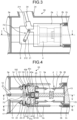
- FIG. 1 is a horizontal cross-sectional view of a vacuum circuit breaker according to a first embodiment.
- FIGS. 2 and 3 are vertical cross-sectional views of the vacuum circuit breaker according to the first embodiment.
- a vacuum circuit breaker 50 is in a closing state in which a first contact point constituted by a movable-side vacuum contact point 5a and a fixed-side vacuum contact point 5b is in contact and a second contact point constituted by a movable-side main contact point 2a and a fixed-side main contact point 2b is in contact.
- FIG. 1 illustrates a horizontal cross section taken along line I-I in FIGS. 2 and 3 . The cross section illustrated in FIG.
- FIG. 1 is a horizontal cross section at a center in a height direction of a tank.
- FIG. 2 illustrates a vertical cross section taken along line II-II in FIG. 1 .
- FIG. 3 illustrates a vertical cross section taken along line III-III in FIG. 1 .
- FIG. 4 is a horizontal cross-sectional view of the vacuum circuit breaker according to the first embodiment.
- FIGS. 5 and 6 are vertical cross-sectional views of the vacuum circuit breaker according to the first embodiment. In FIGS.
- FIG. 4 illustrates a horizontal cross section taken along line IV-IV in FIGS. 5 and 6 .
- the cross section illustrated in FIG. 4 is a horizontal cross section at a center in the height direction of the tank.
- FIG. 5 illustrates a vertical cross section taken along line V-V in FIG. 4 .
- FIG. 6 illustrates a vertical cross section taken along line VI-VI in FIG. 4 .
- the vacuum circuit breaker 50 includes: a cylindrical tank 1 filled with an insulating gas; a vacuum valve 4 insulated and supported in the tank 1, and including the movable-side vacuum contact point 5a and the fixed-side vacuum contact point 5b; and a movable-side external conductor 34 and a fixed-side external conductor (not illustrated) disposed in a pair of bushings 24 extending upward in the tank 1.
- the vacuum valve 4 includes: a vacuum container 26; a movable lead 11 electrically connected to the movable-side vacuum contact point 5a; a fixed lead 13 electrically connected to the fixed-side vacuum contact point 5b; and an expandable bellows 25 that connects a movable-side end surface of the vacuum container 26 and the movable lead 11.
- the movable-side vacuum contact point 5a of the vacuum valve 4 is movable, and the movable-side vacuum contact point 5a moves when the breaking state and the closing state are switched.
- a support plate 3a is installed at a movable-side end portion of the tank 1.
- the support plate 3a has a disk shape in which a hole is formed at a center.
- a fixed-side end portion of the tank 1 is closed by a support plate (not illustrated) having a disk shape without a hole. Note that, in an arrangement direction of the movable-side vacuum contact point 5a and the fixed-side vacuum contact point 5b, a direction from the fixed-side vacuum contact point 5b toward the movable-side vacuum contact point 5a is the "movable side", and a direction from the movable-side vacuum contact point 5a toward the fixed-side vacuum contact point 5b is the "fixed side”.
- the vacuum container 26 accommodates the movable-side vacuum contact point 5a, the fixed-side vacuum contact point 5b, and the fixed lead 13, and the movable lead 11 protrudes outward from one end portion.
- the bellows 25 connects the vacuum container 26 and the movable lead 11, extends in the closing state in which the first contact point constituted by the movable-side vacuum contact point 5a and the fixed-side vacuum contact point 5b is closed, and contracts in the breaking state in which the first contact point constituted by the movable-side vacuum contact point 5a and the fixed-side vacuum contact point 5b is open.
- the vacuum circuit breaker 50 includes: a movable-side shield 8 formed using a conductive material in a tubular shape and installed on the movable side of the vacuum valve 4; a movable-side insulating support cylinder 10 that insulates and supports the movable-side shield 8 on the support plate 3a; and a fixed-side shield 15 installed on the fixed side of the vacuum valve 4.
- the movable-side shield 8 electrically connects a lower end of the movable-side external conductor 34 to the movable lead 11.
- the fixed-side shield 15 electrically connects a lower end of the fixed-side external conductor (not illustrated) to the fixed lead 13.
- the vacuum circuit breaker 50 includes the movable-side main contact point 2a having a tubular shaper to cover the vacuum valve 4 and the movable-side shield 8 from radially outside, and the fixed-side main contact point 2b that is disposed to face the movable-side main contact point 2a.
- the movable-side main contact point 2a is movable, and the movable-side main contact point 2a moves when the breaking state and the closing state are switched.
- the vacuum circuit breaker 50 includes: a contact point driver 70 configured to open and close the first contact point constituted by the movable-side vacuum contact point 5a and the fixed-side vacuum contact point 5b and to open and close the second contact point constituted by the movable-side main contact point 2a and the fixed-side main contact point 2b, by moving the movable-side vacuum contact point 5a and the movable-side main contact point 2a in conjunction with each other; and an insulating rod 12 configured to transmit a force for opening and closing the first contact point and the second contact point in conjunction with each other to the contact point driver 70.
- the contact point driver 70 includes: a contact 43 that is fixed to the movable-side end portion 112 of the movable lead 11, is disposed in a cylinder of the movable-side shield 8, and electrically connects the movable-side shield 8 and the movable lead 11; a low gas pressure section lever 14 disposed in the cylinder of the movable-side shield 8; a link 18 connected to the fixed side of the low gas pressure section lever 14; a low gas pressure section rod 19 connected to the fixed side of the link 18; a contact pressure plate 41 installed on the fixed side of the low gas pressure section rod 19; a contact pressure spring 42 installed between the contact pressure plate 41 and the contact 43; a rotary seal shaft 17 fixed to the low gas pressure section lever 14, penetrating the movable-side shield 8, and having an end portion protruding to a high gas pressure section inside the tank 1 and outside the movable-side shield 8; and a high gas pressure section lever 21 that is fixed to a portion of the rotary seal shaft 17 protruding
- the contact 43 includes a disk-shaped first contact 43a, a disk-shaped second contact 43b having a diameter smaller than that of the first contact 43a and disposed on the movable side with respect to the first contact 43a, and a column portion 43c connecting the first contact 43a and the second contact 43b.
- the rotary seal shaft 17 is rotatably supported by the movable-side shield 8.
- the low gas pressure section lever 14 is disposed in the cylinder of the movable-side shield 8, and is connected to the contact pressure plate 41 via the link 18 and the low gas pressure section rod 19.
- the contact pressure plate 41 has a structure in which a disk-shaped first contact pressure plate 41a and a ring-shaped second contact pressure plate 41b are connected by a cylindrical portion 41c.
- An inner diameter of the second contact pressure plate 41b is smaller than a diameter of the second contact 43b.
- the second contact 43b is disposed in a space between the first contact pressure plate 41a and the second contact pressure plate 41b.
- the contact pressure spring 42 is provided between the second contact pressure plate 41b and the first contact 43a, and the contact pressure plate 41 is in contact with the contact 43 via the contact pressure spring 42.
- the contact pressure plate 41 and the contact pressure spring 42 constitute a contact pressure applier that applies a contact pressure to the contact 43.
- the contact point driver may include an attenuation mechanism that attenuates movement of the contact 43 along an axial direction of the tank 1. The attenuation mechanism is not limited to a specific structure.
- the insulating rod 12 is connected to a shaft 6 of an operation device (not illustrated) installed outside the tank 1.
- a fixed-side end portion 121 of the insulating rod 12 is rotatably fixed to a middle portion of the low gas pressure section lever 14.
- the low gas pressure section lever 14 has a movable-side end portion 142 fixed to the rotary seal shaft 17.
- a fixed-side end portion 141 of the low gas pressure section lever 14 is rotatably fixed to a movable-side end portion 182 of the link 18.
- a fixed-side end portion 181 of the link 18 is rotatably fixed to a movable-side end portion 192 of the low gas pressure section rod 19.
- a fixed-side end portion 191 of the low gas pressure section rod 19 is fixed to the first contact pressure plate 41a.
- the movable-side external conductor 34 is electrically connected to the movable-side vacuum contact point 5a via the movable-side shield 8, the contact 43, and the movable lead 11.
- a stroke of the movable-side vacuum contact point 5a by the contact point driver 70 is longer than a distance between the movable-side vacuum contact point 5a and the fixed-side vacuum contact point 5b in an opened state. Therefore, during a closing operation, the movable-side vacuum contact point 5a and the fixed-side vacuum contact point 5b come into contact with each other before an operation of the contact point driver 70 is completed, and the contact pressure spring 42 is compressed after the movable-side vacuum contact point 5a and the fixed-side vacuum contact point 5b come into contact with each other.
- the contact pressure spring 42 is in a compressed state in the closing state in which the first contact point constituted by the movable-side vacuum contact point 5a and the fixed-side vacuum contact point 5b is closed, and presses the first contact 43a toward the fixed side to apply a contact pressure to the contact 43. Therefore, in the closing state, the movable-side vacuum contact point 5a is pressed against the fixed-side vacuum contact point 5b by the contact pressure spring 42.
- Both end portions of the rotary seal shaft 17 disposed in the high gas pressure section are fixed to a movable-side end portion 212 of the high gas pressure section lever 21.
- a fixed-side end portion 211 of the high gas pressure section lever 21 is rotatably fixed to the movable-side main contact point 2a.
- a length of the high gas pressure section lever 21 is longer than a length of the low gas pressure section lever 14.
- the movable-side main contact point 2a has a tubular shape to cover the movable-side shield 8 and the vacuum valve 4 from radially outside.
- the fixed-side main contact point 2b has a tubular shape having a diameter identical to that of the movable-side main contact point 2a, and is biased toward the movable side by a contact pressure spring 2c.
- the rotary seal shaft 17 is rotatably supported by a bearing 22 installed on the movable-side shield 8.
- a gap between the rotary seal shaft 17 and the movable-side shield 8 is sealed by an airtight material 23, and gas is suppressed from moving through the gap between the rotary seal shaft 17 and the movable-side shield 8.
- the shaft 6 moves to the movable side.
- the low gas pressure section lever 14 connected to the shaft 6 via the insulating rod 12 rotates about the rotary seal shaft 17 such that the fixed-side end portion 141 moves to the movable side.
- the high gas pressure section lever 21 also rotates about the rotary seal shaft 17 such that the fixed-side end portion 211 moves to the movable side.
- the movable-side main contact point 2a fixed to the fixed-side end portion 211 of the high gas pressure section lever 21 moves to the movable side with rotation of the high gas pressure section lever 21. Therefore, when the shaft 6 moves to the movable side, the movable-side main contact point 2a moves to the movable side without delay. Whereas, the low gas pressure section rod 19 and the link 18 fixed to the fixed-side end portion 141 of the low gas pressure section lever 14 move to the movable side with rotation of the low gas pressure section lever 14. However, until the contact pressure spring 42 returns to a natural length, a state is maintained in which the movable-side vacuum contact point 5a is in contact with the fixed-side vacuum contact point 5b.
- the second contact 43b is pulled toward the movable side by the second contact pressure plate 41b along with movement of the low gas pressure section rod 19 toward the movable side, and the contact pressure plate 41, the contact pressure spring 42, the contact 43, the movable lead 11, and the movable-side vacuum contact point 5a move to the movable side to separate the movable-side vacuum contact point 5a from the fixed-side vacuum contact point 5b.
- the movable-side main contact point 2a moves to the movable side without delay when the shaft 6 moves to the movable side, whereas the movable-side vacuum contact point 5a moves to the movable side after the contact pressure spring 42 returns to the natural length. Therefore, the contact point of the vacuum valve 4 is opened after the main contact point is opened first.
- a length of the high gas pressure section lever 21 is longer than a length of the low gas pressure section lever 14. Therefore, a distance between the movable-side vacuum contact point 5a and the fixed-side vacuum contact point 5b in the breaking state is shorter than a distance between the movable-side main contact point 2a and the fixed-side main contact point 2b in the breaking state.
- a length of the high gas pressure section lever 21 is set to twice a length of the low gas pressure section lever 14
- the distance between the movable-side main contact point 2a and the fixed-side main contact point 2b in the breaking state can be made twice the distance between the movable-side vacuum contact point 5a and the fixed-side vacuum contact point 5b in the breaking state.
- the shaft 6 moves to the fixed side.
- the low gas pressure section lever 14 connected to the shaft 6 via the insulating rod 12 rotates about the rotary seal shaft 17 such that the fixed-side end portion 141 moves to the fixed side.
- the high gas pressure section lever 21 also rotates about the rotary seal shaft 17 such that the fixed-side end portion 211 moves to the fixed side.
- the movable-side main contact point 2a fixed to the fixed-side end portion 211 of the high gas pressure section lever 21 moves to the fixed side with rotation of the high gas pressure section lever 21. Therefore, when the shaft 6 moves to the fixed side, the movable-side main contact point 2a moves to the fixed side without delay. Whereas, the low gas pressure section rod 19 and the link 18 fixed to the fixed-side end portion 141 of the low gas pressure section lever 14 move to the fixed side with rotation of the low gas pressure section lever 14.
- the contact pressure plate 41, the contact pressure spring 42, the contact 43, the movable lead 11, and the movable-side vacuum contact point 5a move to the fixed side together with the low gas pressure section rod 19, the movable-side vacuum contact point 5a comes into contact with the fixed-side vacuum contact point 5b. Even after the movable-side vacuum contact point 5a comes into contact with the fixed-side vacuum contact point 5b, the contact pressure spring 42 is compressed as the low gas pressure section rod 19 continues to move to the fixed side.
- the movable-side main contact point 2a and the movable-side vacuum contact point 5a move to the fixed side without delay.
- the contact point of the vacuum valve 4 is designed to be closed before the main contact point during the closing operation, the contact pressure spring 42 is compressed until the main contact point is closed after the contact point of the vacuum valve 4 is closed.
- FIGS. 7 and 8 are vertical cross-sectional views of a vacuum circuit breaker according to a first modification of the first embodiment.
- the vacuum circuit breaker 50 according to the first modification of the first embodiment is different from the vacuum circuit breaker according to the first embodiment in having a structure called a tulip shape in which an outer cylindrical surface of the movable-side main contact point 2a and an inner cylindrical surface of the fixed-side main contact point 2b are in contact with each other.
- the vacuum circuit breaker 50 according to the first modification of the first embodiment is similar to the vacuum circuit breaker 50 according to the first embodiment except that the main contact point has a different structure.
- the main contact point can be opened first and then the contact point of the vacuum valve 4 can be opened during the opening operation, and the contact point of the vacuum valve 4 is designed to be closed before the main contact point during the closing operation. Therefore, after the contact point of the vacuum valve 4 is closed, the contact pressure spring 42 is compressed until the main contact point is closed.
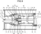
- FIG. 9 is a horizontal cross-sectional view of a vacuum circuit breaker according to a second modification of the first embodiment.
- the vacuum circuit breaker 50 according to the second modification of the first embodiment is different from the vacuum circuit breaker 50 according to the first embodiment in that a closing resistor 81 is connected to the fixed-side main contact point 2b.
- a closing resistor 81 is connected to the fixed-side main contact point 2b.
- the vacuum circuit breaker 50 may have a structure in which a movable-side resistance contact point and a fixed-side resistance contact point are provided separately from the movable-side main contact point 2a and the fixed-side main contact point 2b, and a closing resistor is connected to the fixed-side resistance contact point.
- the vacuum circuit breaker 50 provided with the movable-side resistance contact point and the fixed-side resistance contact point separately from the movable-side main contact point 2a and the fixed-side main contact point 2b can also suppress system disturbance at the time of system connection.
- the vacuum circuit breaker 50 transmits a driving force for opening and closing the main contact point to the high gas pressure section lever 21 through the rotary seal shaft 17 rotating together with the low gas pressure section lever 14, and the mechanism for opening and closing the contact point of the vacuum valve 4 and the mechanism for opening and closing the main contact point are partially shared. Therefore, as compared with a vacuum circuit breaker in which the mechanism for opening and closing the contact point of the vacuum valve and the mechanism for opening and closing the main contact point are separately provided, a device size can be downsized. In addition, since the main contact point is provided separately from the contact point of the vacuum valve 4, a large current can be applied.
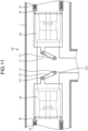
- FIGS. 10 and 11 are vertical cross-sectional views of a vacuum circuit breaker according to a second embodiment.
- the vacuum circuit breaker 50 according to the second embodiment includes: the cylindrical tank 1 filled with an insulating gas; and two vacuum valves 4 that are insulated and supported in the tank 1 and each includes the movable-side vacuum contact point 5a and the fixed-side vacuum contact point 5b. Further, the vacuum circuit breaker 50 also includes the insulating rod 12 that moves in a direction perpendicular to a longitudinal direction of the tank 1.
- an origin 0 is defined at a center in the longitudinal direction of the tank 1 and at a center of a cross section perpendicular to the longitudinal direction.
- an X axis is defined in the longitudinal direction of the tank 1, and a Y axis is defined in a movable direction of the insulating rod 12.
- a direction from the fixed-side vacuum contact point 5b toward the movable-side vacuum contact point 5a is defined as a "movable side”
- a direction from the movable-side vacuum contact point 5a toward the fixed-side vacuum contact point 5b is defined as a "fixed side”
- a smaller coordinate value of the X axis is located on the "movable side” in two points in a region where the coordinate value of the X axis is positive.
- moving in a direction in which the coordinate value of the X axis decreases means “moving to the movable side" in the region where the coordinate value of the X axis is positive; and moving in a direction in which the coordinate value of the X axis increases means “moving to the movable side” in the region where the coordinate value of the X axis is negative.
- moving in a direction in which the coordinate value of the X axis increases means “moving to the fixed side” in the region where the coordinate value of the X axis is positive
- moving in a direction in which the coordinate value of the X axis decreases means “moving to the fixed side” in the region where the coordinate value of the X axis is negative. That is, moving in a direction in which an absolute value of the coordinate value of the X axis decreases means “moving to the movable side”
- moving in a direction in which the absolute value of the coordinate value of the X axis increases means “moving to the fixed side”.
- the fixed-side vacuum contact point 5b of each of the two vacuum valves 4 is connected to an external conductor (not illustrated) via the fixed lead 13 and the fixed-side shield 15. That is, the vacuum circuit breaker 50 according to the second embodiment has a two-break structure opened and closed at two points between the external conductors.
- the low gas pressure section lever 14 includes a first lever 44 and a second lever 45, and a fixed-side end portion 441 of the first lever 44 and a movable-side end portion 452 of the second lever 45 are fixed to the rotary seal shaft 17.
- the first lever 44 and the second lever 45 form an angle with each other in a plane perpendicular to the rotary seal shaft 17.
- a movable-side end portion 442 of the first lever 44 is rotatably fixed to the insulating rod 12.
- a fixed-side end portion 451 of the second lever 45 is rotatably fixed to the movable-side end portion 182 of the link 18.
- the fixed-side end portion 181 of the link 18 is rotatably fixed to the movable-side end portion 192 of the low gas pressure section rod 19.
- the contact pressure plate 41 has a structure in which the disk-shaped first contact pressure plate 41a and the ring-shaped second contact pressure plate 41b are connected by the cylindrical portion 41c, and an inner diameter of the second contact pressure plate 41b is smaller than a diameter of the second contact 43b.
- the contact 43 includes: the disk-shaped first contact 43a; the disk-shaped second contact 43b having a diameter smaller than that of the first contact 43a and disposed on the movable side with respect to the first contact 43a; and the column portion 43c connecting the first contact 43a and the second contact 43b, where the first contact 43a is fixed to the movable-side end portion 112 of the movable lead 11.
- the second contact 43b is disposed in a space between the first contact pressure plate 41a and the second contact pressure plate 41b.
- the contact pressure spring 42 is provided between the second contact pressure plate 41b and the first contact 43a, and the contact pressure plate 41 is in contact with the contact 43 via the contact pressure spring 42.
- the contact pressure spring 42 is in a compressed state in a closing state in which the first contact point constituted by the movable-side vacuum contact point 5a and the fixed-side vacuum contact point 5b is closed, and presses the first contact 43a toward the fixed side to apply a contact pressure to the contact 43. Therefore, in the closing state, the movable-side vacuum contact point 5a is pressed against the fixed-side vacuum contact point 5b by the contact pressure spring 42.
- the movable-side end portion 212 of the high gas pressure section lever 21 is fixed to a portion of the rotary seal shaft 17 disposed in the high gas pressure section.
- a length of the high gas pressure section lever 21 is longer than a length of the low gas pressure section lever 14.
- the fixed-side end portion 211 of the high gas pressure section lever 21 is rotatably fixed to the movable-side main contact point 2a.
- the movable-side main contact point 2a has a tubular shape to cover the movable-side shield 8 and the vacuum valve 4 from radially outside.
- the rotary seal shaft 17 is rotatably supported by a bearing (not illustrated) installed on the movable-side shield 8.
- a gap between the rotary seal shaft 17 and the movable-side shield 8 is sealed by an airtight material (not illustrated), and gas is suppressed from moving through the gap between the rotary seal shaft 17 and the movable-side shield 8.
- the insulating rod 12 moves in a -Y direction of being pulled out from the tank 1.
- the low gas pressure section lever 14 fixed to the insulating rod 12 rotates about the rotary seal shaft 17 such that an absolute value of a coordinate value of the X axis of the fixed-side end portion 441 of the first lever 44 decreases.
- the high gas pressure section lever 21 also rotates about the rotary seal shaft 17 such that an absolute value of a coordinate value of the X axis of the fixed-side end portion 211 decreases.
- the movable-side main contact point 2a fixed to the fixed-side end portion 211 of the high gas pressure section lever 21 moves in a direction in which an absolute value of a coordinate value of the X axis decreases, with rotation of the high gas pressure section lever 21. Therefore, when the insulating rod 12 moves in the -Y direction, the movable-side main contact point 2a moves in a direction in which the absolute value of the coordinate value of the X axis decreases without delay. Whereas, the link 18 and the low gas pressure section rod 19 fixed to the fixed-side end portion 451 of the second lever 45 move in a direction in which the absolute value of the coordinate value of the X axis decreases, with rotation of the low gas pressure section lever 14.
- the contact pressure spring 42 returns to a natural length, a state is maintained in which the movable-side vacuum contact point 5a is in contact with the fixed-side vacuum contact point 5b.
- the second contact 43b is pulled in a direction in which the absolute value of the coordinate value of the X axis decreases by the second contact pressure plate 41b as the low gas pressure section rod 19 moves in a direction in which the absolute value of the coordinate value of the X axis decreases, and the contact pressure plate 41, the contact pressure spring 42, the contact 43, the movable lead 11, and the movable-side vacuum contact point 5a move in a direction in which the absolute value of the coordinate value of the X axis decreases, to separate the movable-side vacuum contact point 5a from the fixed-side vacuum contact point 5b.
- the movable-side main contact point 2a moves in the direction in which the absolute value of the coordinate value of the X axis decreases without delay when the insulating rod 12 moves in the -Y direction
- the movable-side vacuum contact point 5a moves in the direction in which the absolute value of the coordinate value of the X axis decreases after the contact pressure spring 42 returns to the natural length. Therefore, the contact point of the vacuum valve 4 is opened after the main contact point is opened first.
- the insulating rod 12 moves in a +Y direction, which is a direction of being pushed into the tank 1.
- the low gas pressure section lever 14 fixed to the insulating rod 12 rotates about the rotary seal shaft 17 such that an absolute value of a coordinate value of the X axis of the fixed-side end portion 441 of the first lever 44 increases.
- the high gas pressure section lever 21 also rotates about the rotary seal shaft 17 such that an absolute value of a coordinate value of the X axis of the fixed-side end portion 211 increases.
- the movable-side main contact point 2a fixed to the fixed-side end portion 211 of the high gas pressure section lever 21 moves in a direction in which an absolute value of a coordinate value of the X axis increases, with rotation of the high gas pressure section lever 21. Therefore, when the insulating rod 12 moves in the +Y direction, the movable-side main contact point 2a moves in a direction in which the absolute value of the coordinate value of the X axis increases without delay. Whereas, the link 18 and the low gas pressure section rod 19 fixed to the fixed-side end portion 451 of the second lever 45 move in a direction in which the absolute value of the coordinate value of the X axis increases, with rotation of the low gas pressure section lever 14.
- the contact pressure plate 41, the contact pressure spring 42, the contact 43, the movable lead 11, and the movable-side vacuum contact point 5a move together with the low gas pressure section rod 19 in a direction in which the absolute value of the coordinate value of the X axis increases, and the movable-side vacuum contact point 5a comes into contact with the fixed-side vacuum contact point 5b. Even after the movable-side vacuum contact point 5a comes into contact with the fixed-side vacuum contact point 5b, the contact pressure spring 42 is compressed as the low gas pressure section rod 19 continues to move to the fixed side.
- the vacuum circuit breaker 50 transmits a driving force for opening and closing the main contact point to the high gas pressure section lever 21 through the rotary seal shaft 17 rotating together with the low gas pressure section lever 14, and the mechanism for opening and closing the contact point of the vacuum valve 4 and the mechanism for opening and closing the main contact point are partially shared. Therefore, as compared with a vacuum circuit breaker in which the mechanism for opening and closing the contact point of the vacuum valve 4 and the mechanism for opening and closing the main contact point are separately provided, a device size can be downsized. In addition, since the main contact point is provided separately from the contact point of the vacuum valve 4, a large current can be applied.
- the vacuum circuit breaker 50 having a two-break structure opened and closed at two points between the external conductors has been described here, the vacuum circuit breaker 50 may have a multi-break structure opened and closed at three or more points between the external conductors.
Landscapes
- Engineering & Computer Science (AREA)
- Power Engineering (AREA)
- High-Tension Arc-Extinguishing Switches Without Spraying Means (AREA)
- Gas-Insulated Switchgears (AREA)
Abstract
Description
- The present disclosure relates to a vacuum circuit breaker including a vacuum valve installed in a tank.
- A bellows used to drive a contact point of a vacuum valve is buckled when a pressure difference between an inner surface and an outer surface thereof is large.
Patent Literature 1 proposes enhancing durability of a bellows by making a pressure in a bellows inner peripheral side space of a vacuum valve to be lower than a pressure in a tank, and dividing a gas pressure section including the bellows and another gas pressure section. - Patent Literature 1: International Publication No.
2012/063501 - When an energizing current increases, it becomes difficult for a vacuum circuit breaker to keep a temperature rise value of a vacuum valve at a time of breaking within a design range. For this reason, a structure in which a main contact point is provided separately from a contact point of the vacuum valve is used for a vacuum circuit breaker that breaks a large current.
- In order to achieve both downsizing of equipment and an increase in energizing current, it is necessary to separate a pressure section including the bellows and another gas pressure section while providing the main contact point different from the vacuum valve. However, separately providing a mechanism for opening and closing the contact point of the vacuum valve in the pressure section including the bellows and a mechanism for opening and closing the main contact point in another gas pressure section hinders reduction of a device size of the vacuum circuit breaker.
- The present disclosure has been made in view of the above, and an object of the present disclosure is to provide a vacuum circuit breaker that achieves both downsizing of equipment and an increase in energizing current.
- In order to solve the above-described problem and achieve the object, a vacuum circuit breaker according to the present disclosure includes: a tank having a cylindrical shape; a vacuum valve accommodated in the tank and including a movable-side vacuum contact point, a fixed-side vacuum contact point, a movable lead electrically connected to the movable-side vacuum contact point, and a fixed lead electrically connected to the fixed-side vacuum contact point; a movable-side shield formed using a conductive material in a tubular shape and installed on a movable side of the vacuum valve; a movable-side main contact point having a tubular shape configured to cover the vacuum valve and the movable-side shield from radially outside; a fixed-side main contact point disposed to face the movable-side main contact point; a contact point driver configured to open and close a first contact point constituted by the movable-side vacuum contact point and the fixed-side vacuum contact point, and to open and close a second contact point constituted by the movable-side main contact point and the fixed-side main contact point, by moving the movable-side vacuum contact point and the movable-side main contact point in conjunction with each other; and an insulating rod configured to transmit a force for opening and closing the first contact point and the second contact point in conjunction with each other to the contact point driver. The contact point driver includes: a contact configured to electrically connect the movable-side shield and the movable lead, and is fixed to a movable-side end portion of the movable lead and disposed in a cylinder of the movable-side shield; a low gas pressure section lever disposed in a cylinder of the movable-side shield and connected to the contact via a contact pressure applier configured to apply a contact pressure to the contact; a rotary seal shaft fixed to the low gas pressure section lever, rotatably supported by the movable-side shield, penetrating the movable-side shield, and having an end portion exposed to a high gas pressure section inside the tank and outside the movable-side shield; and a high gas pressure section lever fixed to a portion of the rotary seal shaft exposed to the high gas pressure section and rotatably connected to the movable-side main contact point. An airtight material seals between the movable-side shield and the rotary seal shaft.
- According to the present disclosure, it is possible to obtain a vacuum circuit breaker that achieves both downsizing of equipment and an increase in energizing current.
-
-
FIG. 1 is a horizontal cross-sectional view of a vacuum circuit breaker according to a first embodiment. -
FIG. 2 is a vertical cross-sectional view of the vacuum circuit breaker according to the first embodiment. -
FIG. 3 is a vertical cross-sectional view of the vacuum circuit breaker according to the first embodiment. -
FIG. 4 is a horizontal cross-sectional view of the vacuum circuit breaker according to the first embodiment. -
FIG. 5 is a vertical cross-sectional view of the vacuum circuit breaker according to the first embodiment. -
FIG. 6 is a vertical cross-sectional view of the vacuum circuit breaker according to the first embodiment. -
FIG. 7 is a vertical cross-sectional view of a vacuum circuit breaker according to a first modification of the first embodiment. -
FIG. 8 is a vertical cross-sectional view of the vacuum circuit breaker according to the first modification of the first embodiment. -
FIG. 9 is a horizontal cross-sectional view of a vacuum circuit breaker according to a second modification of the first embodiment. -
FIG. 10 is a vertical cross-sectional view of a vacuum circuit breaker according to a second embodiment. -
FIG. 11 is a vertical cross-sectional view of the vacuum circuit breaker according to the second embodiment. - Hereinafter, a vacuum circuit breaker according to embodiments will be described in detail with reference to the drawings.
-
FIG. 1 is a horizontal cross-sectional view of a vacuum circuit breaker according to a first embodiment.FIGS. 2 and3 are vertical cross-sectional views of the vacuum circuit breaker according to the first embodiment. InFIGS. 1, 2 , and3 , avacuum circuit breaker 50 is in a closing state in which a first contact point constituted by a movable-sidevacuum contact point 5a and a fixed-sidevacuum contact point 5b is in contact and a second contact point constituted by a movable-sidemain contact point 2a and a fixed-sidemain contact point 2b is in contact.FIG. 1 illustrates a horizontal cross section taken along line I-I inFIGS. 2 and3 . The cross section illustrated inFIG. 1 is a horizontal cross section at a center in a height direction of a tank.FIG. 2 illustrates a vertical cross section taken along line II-II inFIG. 1 .FIG. 3 illustrates a vertical cross section taken along line III-III inFIG. 1 .FIG. 4 is a horizontal cross-sectional view of the vacuum circuit breaker according to the first embodiment.FIGS. 5 and 6 are vertical cross-sectional views of the vacuum circuit breaker according to the first embodiment. InFIGS. 4 ,5, and 6 , thevacuum circuit breaker 50 is in a breaking state in which the first contact point constituted by the movable-sidevacuum contact point 5a and the fixed-sidevacuum contact point 5b is open and the second contact point constituted by the movable-sidemain contact point 2a and the fixed-sidemain contact point 2b is open.FIG. 4 illustrates a horizontal cross section taken along line IV-IV inFIGS. 5 and 6 . The cross section illustrated inFIG. 4 is a horizontal cross section at a center in the height direction of the tank.FIG. 5 illustrates a vertical cross section taken along line V-V inFIG. 4 .FIG. 6 illustrates a vertical cross section taken along line VI-VI inFIG. 4 . Thevacuum circuit breaker 50 according to the first embodiment includes: acylindrical tank 1 filled with an insulating gas; avacuum valve 4 insulated and supported in thetank 1, and including the movable-sidevacuum contact point 5a and the fixed-sidevacuum contact point 5b; and a movable-sideexternal conductor 34 and a fixed-side external conductor (not illustrated) disposed in a pair ofbushings 24 extending upward in thetank 1. - The
vacuum valve 4 includes: avacuum container 26; amovable lead 11 electrically connected to the movable-sidevacuum contact point 5a; afixed lead 13 electrically connected to the fixed-sidevacuum contact point 5b; and anexpandable bellows 25 that connects a movable-side end surface of thevacuum container 26 and themovable lead 11. The movable-sidevacuum contact point 5a of thevacuum valve 4 is movable, and the movable-sidevacuum contact point 5a moves when the breaking state and the closing state are switched. Asupport plate 3a is installed at a movable-side end portion of thetank 1. Thesupport plate 3a has a disk shape in which a hole is formed at a center. A fixed-side end portion of thetank 1 is closed by a support plate (not illustrated) having a disk shape without a hole. Note that, in an arrangement direction of the movable-sidevacuum contact point 5a and the fixed-sidevacuum contact point 5b, a direction from the fixed-sidevacuum contact point 5b toward the movable-sidevacuum contact point 5a is the "movable side", and a direction from the movable-sidevacuum contact point 5a toward the fixed-sidevacuum contact point 5b is the "fixed side". - The
vacuum container 26 accommodates the movable-sidevacuum contact point 5a, the fixed-sidevacuum contact point 5b, and thefixed lead 13, and themovable lead 11 protrudes outward from one end portion. Thebellows 25 connects thevacuum container 26 and themovable lead 11, extends in the closing state in which the first contact point constituted by the movable-sidevacuum contact point 5a and the fixed-sidevacuum contact point 5b is closed, and contracts in the breaking state in which the first contact point constituted by the movable-sidevacuum contact point 5a and the fixed-sidevacuum contact point 5b is open. - Further, the
vacuum circuit breaker 50 includes: a movable-side shield 8 formed using a conductive material in a tubular shape and installed on the movable side of thevacuum valve 4; a movable-sideinsulating support cylinder 10 that insulates and supports the movable-side shield 8 on thesupport plate 3a; and a fixed-side shield 15 installed on the fixed side of thevacuum valve 4. The movable-side shield 8 electrically connects a lower end of the movable-sideexternal conductor 34 to themovable lead 11. The fixed-side shield 15 electrically connects a lower end of the fixed-side external conductor (not illustrated) to thefixed lead 13. - In addition, the
vacuum circuit breaker 50 includes the movable-sidemain contact point 2a having a tubular shaper to cover thevacuum valve 4 and the movable-side shield 8 from radially outside, and the fixed-sidemain contact point 2b that is disposed to face the movable-sidemain contact point 2a. In thevacuum circuit breaker 50, the movable-sidemain contact point 2a is movable, and the movable-sidemain contact point 2a moves when the breaking state and the closing state are switched. - Further, the
vacuum circuit breaker 50 includes: acontact point driver 70 configured to open and close the first contact point constituted by the movable-sidevacuum contact point 5a and the fixed-sidevacuum contact point 5b and to open and close the second contact point constituted by the movable-sidemain contact point 2a and the fixed-sidemain contact point 2b, by moving the movable-sidevacuum contact point 5a and the movable-sidemain contact point 2a in conjunction with each other; and aninsulating rod 12 configured to transmit a force for opening and closing the first contact point and the second contact point in conjunction with each other to thecontact point driver 70. - The
contact point driver 70 includes: acontact 43 that is fixed to the movable-side end portion 112 of themovable lead 11, is disposed in a cylinder of the movable-side shield 8, and electrically connects the movable-side shield 8 and themovable lead 11; a low gaspressure section lever 14 disposed in the cylinder of the movable-side shield 8; alink 18 connected to the fixed side of the low gaspressure section lever 14; a low gaspressure section rod 19 connected to the fixed side of thelink 18; acontact pressure plate 41 installed on the fixed side of the low gaspressure section rod 19; acontact pressure spring 42 installed between thecontact pressure plate 41 and thecontact 43; arotary seal shaft 17 fixed to the low gaspressure section lever 14, penetrating the movable-side shield 8, and having an end portion protruding to a high gas pressure section inside thetank 1 and outside the movable-side shield 8; and a high gaspressure section lever 21 that is fixed to a portion of therotary seal shaft 17 protruding to the high gas pressure section, and is rotatably connected to the movable-sidemain contact point 2a. - The
contact 43 includes a disk-shapedfirst contact 43a, a disk-shapedsecond contact 43b having a diameter smaller than that of thefirst contact 43a and disposed on the movable side with respect to thefirst contact 43a, and acolumn portion 43c connecting thefirst contact 43a and thesecond contact 43b. Therotary seal shaft 17 is rotatably supported by the movable-side shield 8. The low gaspressure section lever 14 is disposed in the cylinder of the movable-side shield 8, and is connected to thecontact pressure plate 41 via thelink 18 and the low gaspressure section rod 19. Thecontact pressure plate 41 has a structure in which a disk-shaped firstcontact pressure plate 41a and a ring-shaped secondcontact pressure plate 41b are connected by acylindrical portion 41c. An inner diameter of the secondcontact pressure plate 41b is smaller than a diameter of thesecond contact 43b. Thesecond contact 43b is disposed in a space between the firstcontact pressure plate 41a and the secondcontact pressure plate 41b. Thecontact pressure spring 42 is provided between the secondcontact pressure plate 41b and thefirst contact 43a, and thecontact pressure plate 41 is in contact with thecontact 43 via thecontact pressure spring 42. Thecontact pressure plate 41 and thecontact pressure spring 42 constitute a contact pressure applier that applies a contact pressure to thecontact 43. Note that, the contact point driver may include an attenuation mechanism that attenuates movement of thecontact 43 along an axial direction of thetank 1. The attenuation mechanism is not limited to a specific structure. - The insulating
rod 12 is connected to ashaft 6 of an operation device (not illustrated) installed outside thetank 1. A fixed-side end portion 121 of the insulatingrod 12 is rotatably fixed to a middle portion of the low gaspressure section lever 14. - The low gas
pressure section lever 14 has a movable-side end portion 142 fixed to therotary seal shaft 17. A fixed-side end portion 141 of the low gaspressure section lever 14 is rotatably fixed to a movable-side end portion 182 of thelink 18. A fixed-side end portion 181 of thelink 18 is rotatably fixed to a movable-side end portion 192 of the low gaspressure section rod 19. A fixed-side end portion 191 of the low gaspressure section rod 19 is fixed to the firstcontact pressure plate 41a. The movable-sideexternal conductor 34 is electrically connected to the movable-sidevacuum contact point 5a via the movable-side shield 8, thecontact 43, and themovable lead 11. A stroke of the movable-sidevacuum contact point 5a by thecontact point driver 70 is longer than a distance between the movable-sidevacuum contact point 5a and the fixed-sidevacuum contact point 5b in an opened state. Therefore, during a closing operation, the movable-sidevacuum contact point 5a and the fixed-sidevacuum contact point 5b come into contact with each other before an operation of thecontact point driver 70 is completed, and thecontact pressure spring 42 is compressed after the movable-sidevacuum contact point 5a and the fixed-sidevacuum contact point 5b come into contact with each other. For this reason, thecontact pressure spring 42 is in a compressed state in the closing state in which the first contact point constituted by the movable-sidevacuum contact point 5a and the fixed-sidevacuum contact point 5b is closed, and presses thefirst contact 43a toward the fixed side to apply a contact pressure to thecontact 43. Therefore, in the closing state, the movable-sidevacuum contact point 5a is pressed against the fixed-sidevacuum contact point 5b by thecontact pressure spring 42. - Both end portions of the
rotary seal shaft 17 disposed in the high gas pressure section are fixed to a movable-side end portion 212 of the high gaspressure section lever 21. A fixed-side end portion 211 of the high gaspressure section lever 21 is rotatably fixed to the movable-sidemain contact point 2a. A length of the high gaspressure section lever 21 is longer than a length of the low gaspressure section lever 14. The movable-sidemain contact point 2a has a tubular shape to cover the movable-side shield 8 and thevacuum valve 4 from radially outside. The fixed-sidemain contact point 2b has a tubular shape having a diameter identical to that of the movable-sidemain contact point 2a, and is biased toward the movable side by acontact pressure spring 2c. - As illustrated in
FIG. 1 , therotary seal shaft 17 is rotatably supported by a bearing 22 installed on the movable-side shield 8. A gap between therotary seal shaft 17 and the movable-side shield 8 is sealed by anairtight material 23, and gas is suppressed from moving through the gap between therotary seal shaft 17 and the movable-side shield 8. - When a breaking command is input to the operation device (not illustrated), the
shaft 6 moves to the movable side. The low gaspressure section lever 14 connected to theshaft 6 via the insulatingrod 12 rotates about therotary seal shaft 17 such that the fixed-side end portion 141 moves to the movable side. Further, when therotary seal shaft 17 rotates together with the low gaspressure section lever 14, the high gaspressure section lever 21 also rotates about therotary seal shaft 17 such that the fixed-side end portion 211 moves to the movable side. - The movable-side
main contact point 2a fixed to the fixed-side end portion 211 of the high gaspressure section lever 21 moves to the movable side with rotation of the high gaspressure section lever 21. Therefore, when theshaft 6 moves to the movable side, the movable-sidemain contact point 2a moves to the movable side without delay. Whereas, the low gaspressure section rod 19 and thelink 18 fixed to the fixed-side end portion 141 of the low gaspressure section lever 14 move to the movable side with rotation of the low gaspressure section lever 14. However, until thecontact pressure spring 42 returns to a natural length, a state is maintained in which the movable-sidevacuum contact point 5a is in contact with the fixed-sidevacuum contact point 5b. After thecontact pressure spring 42 returns to the natural length, thesecond contact 43b is pulled toward the movable side by the secondcontact pressure plate 41b along with movement of the low gaspressure section rod 19 toward the movable side, and thecontact pressure plate 41, thecontact pressure spring 42, thecontact 43, themovable lead 11, and the movable-sidevacuum contact point 5a move to the movable side to separate the movable-sidevacuum contact point 5a from the fixed-sidevacuum contact point 5b. - In this way, the movable-side
main contact point 2a moves to the movable side without delay when theshaft 6 moves to the movable side, whereas the movable-sidevacuum contact point 5a moves to the movable side after thecontact pressure spring 42 returns to the natural length. Therefore, the contact point of thevacuum valve 4 is opened after the main contact point is opened first. - A length of the high gas
pressure section lever 21 is longer than a length of the low gaspressure section lever 14. Therefore, a distance between the movable-sidevacuum contact point 5a and the fixed-sidevacuum contact point 5b in the breaking state is shorter than a distance between the movable-sidemain contact point 2a and the fixed-sidemain contact point 2b in the breaking state. For example, by setting a length of the high gaspressure section lever 21 to twice a length of the low gaspressure section lever 14, the distance between the movable-sidemain contact point 2a and the fixed-sidemain contact point 2b in the breaking state can be made twice the distance between the movable-sidevacuum contact point 5a and the fixed-sidevacuum contact point 5b in the breaking state. - When a closing command is input to the operation device (not illustrated), the
shaft 6 moves to the fixed side. The low gaspressure section lever 14 connected to theshaft 6 via the insulatingrod 12 rotates about therotary seal shaft 17 such that the fixed-side end portion 141 moves to the fixed side. Further, when therotary seal shaft 17 rotates together with the low gaspressure section lever 14, the high gaspressure section lever 21 also rotates about therotary seal shaft 17 such that the fixed-side end portion 211 moves to the fixed side. - The movable-side
main contact point 2a fixed to the fixed-side end portion 211 of the high gaspressure section lever 21 moves to the fixed side with rotation of the high gaspressure section lever 21. Therefore, when theshaft 6 moves to the fixed side, the movable-sidemain contact point 2a moves to the fixed side without delay. Whereas, the low gaspressure section rod 19 and thelink 18 fixed to the fixed-side end portion 141 of the low gaspressure section lever 14 move to the fixed side with rotation of the low gaspressure section lever 14. When thecontact pressure plate 41, thecontact pressure spring 42, thecontact 43, themovable lead 11, and the movable-sidevacuum contact point 5a move to the fixed side together with the low gaspressure section rod 19, the movable-sidevacuum contact point 5a comes into contact with the fixed-sidevacuum contact point 5b. Even after the movable-sidevacuum contact point 5a comes into contact with the fixed-sidevacuum contact point 5b, thecontact pressure spring 42 is compressed as the low gaspressure section rod 19 continues to move to the fixed side. - As described above, when the
shaft 6 moves to the fixed side, the movable-sidemain contact point 2a and the movable-sidevacuum contact point 5a move to the fixed side without delay. In addition, since the contact point of thevacuum valve 4 is designed to be closed before the main contact point during the closing operation, thecontact pressure spring 42 is compressed until the main contact point is closed after the contact point of thevacuum valve 4 is closed. -
FIGS. 7 and 8 are vertical cross-sectional views of a vacuum circuit breaker according to a first modification of the first embodiment. Thevacuum circuit breaker 50 according to the first modification of the first embodiment is different from the vacuum circuit breaker according to the first embodiment in having a structure called a tulip shape in which an outer cylindrical surface of the movable-sidemain contact point 2a and an inner cylindrical surface of the fixed-sidemain contact point 2b are in contact with each other. Thevacuum circuit breaker 50 according to the first modification of the first embodiment is similar to thevacuum circuit breaker 50 according to the first embodiment except that the main contact point has a different structure. Even if the main contact point has the tulip shape, the main contact point can be opened first and then the contact point of thevacuum valve 4 can be opened during the opening operation, and the contact point of thevacuum valve 4 is designed to be closed before the main contact point during the closing operation. Therefore, after the contact point of thevacuum valve 4 is closed, thecontact pressure spring 42 is compressed until the main contact point is closed. -
FIG. 9 is a horizontal cross-sectional view of a vacuum circuit breaker according to a second modification of the first embodiment. Thevacuum circuit breaker 50 according to the second modification of the first embodiment is different from thevacuum circuit breaker 50 according to the first embodiment in that a closingresistor 81 is connected to the fixed-sidemain contact point 2b. By connecting the closingresistor 81 to the fixed-sidemain contact point 2b, system disturbance at a time of system connection can be suppressed. Note that thevacuum circuit breaker 50 may have a structure in which a movable-side resistance contact point and a fixed-side resistance contact point are provided separately from the movable-sidemain contact point 2a and the fixed-sidemain contact point 2b, and a closing resistor is connected to the fixed-side resistance contact point. Thevacuum circuit breaker 50 provided with the movable-side resistance contact point and the fixed-side resistance contact point separately from the movable-sidemain contact point 2a and the fixed-sidemain contact point 2b can also suppress system disturbance at the time of system connection. - The
vacuum circuit breaker 50 according to the first embodiment transmits a driving force for opening and closing the main contact point to the high gaspressure section lever 21 through therotary seal shaft 17 rotating together with the low gaspressure section lever 14, and the mechanism for opening and closing the contact point of thevacuum valve 4 and the mechanism for opening and closing the main contact point are partially shared. Therefore, as compared with a vacuum circuit breaker in which the mechanism for opening and closing the contact point of the vacuum valve and the mechanism for opening and closing the main contact point are separately provided, a device size can be downsized. In addition, since the main contact point is provided separately from the contact point of thevacuum valve 4, a large current can be applied. -
FIGS. 10 and11 are vertical cross-sectional views of a vacuum circuit breaker according to a second embodiment. Thevacuum circuit breaker 50 according to the second embodiment includes: thecylindrical tank 1 filled with an insulating gas; and twovacuum valves 4 that are insulated and supported in thetank 1 and each includes the movable-sidevacuum contact point 5a and the fixed-sidevacuum contact point 5b. Further, thevacuum circuit breaker 50 also includes the insulatingrod 12 that moves in a direction perpendicular to a longitudinal direction of thetank 1. Here, an origin 0 is defined at a center in the longitudinal direction of thetank 1 and at a center of a cross section perpendicular to the longitudinal direction. In addition, an X axis is defined in the longitudinal direction of thetank 1, and a Y axis is defined in a movable direction of the insulatingrod 12. Similarly to the first embodiment, in an arrangement direction of the movable-sidevacuum contact point 5a and the fixed-sidevacuum contact point 5b, when a direction from the fixed-sidevacuum contact point 5b toward the movable-sidevacuum contact point 5a is defined as a "movable side", and a direction from the movable-sidevacuum contact point 5a toward the fixed-sidevacuum contact point 5b is defined as a "fixed side", a smaller coordinate value of the X axis is located on the "movable side" in two points in a region where the coordinate value of the X axis is positive. Similarly, in two points in a region where the coordinate value of the X axis is negative, a larger coordinate value of the X axis is located on the "movable side". Therefore, moving in a direction in which the coordinate value of the X axis decreases means "moving to the movable side" in the region where the coordinate value of the X axis is positive; and moving in a direction in which the coordinate value of the X axis increases means "moving to the movable side" in the region where the coordinate value of the X axis is negative. In addition, moving in a direction in which the coordinate value of the X axis increases means "moving to the fixed side" in the region where the coordinate value of the X axis is positive, and moving in a direction in which the coordinate value of the X axis decreases means "moving to the fixed side" in the region where the coordinate value of the X axis is negative. That is, moving in a direction in which an absolute value of the coordinate value of the X axis decreases means "moving to the movable side", and moving in a direction in which the absolute value of the coordinate value of the X axis increases means "moving to the fixed side". - The fixed-side
vacuum contact point 5b of each of the twovacuum valves 4 is connected to an external conductor (not illustrated) via the fixedlead 13 and the fixed-side shield 15. That is, thevacuum circuit breaker 50 according to the second embodiment has a two-break structure opened and closed at two points between the external conductors. - The low gas
pressure section lever 14 includes afirst lever 44 and asecond lever 45, and a fixed-side end portion 441 of thefirst lever 44 and a movable-side end portion 452 of thesecond lever 45 are fixed to therotary seal shaft 17. Thefirst lever 44 and thesecond lever 45 form an angle with each other in a plane perpendicular to therotary seal shaft 17. A movable-side end portion 442 of thefirst lever 44 is rotatably fixed to the insulatingrod 12. A fixed-side end portion 451 of thesecond lever 45 is rotatably fixed to the movable-side end portion 182 of thelink 18. The fixed-side end portion 181 of thelink 18 is rotatably fixed to the movable-side end portion 192 of the low gaspressure section rod 19. The fixed-side end portion 191 of the low gaspressure section rod 19 is fixed to thecontact pressure plate 41. Similarly to thevacuum circuit breaker 50 according to the first embodiment, thecontact pressure plate 41 has a structure in which the disk-shaped firstcontact pressure plate 41a and the ring-shaped secondcontact pressure plate 41b are connected by thecylindrical portion 41c, and an inner diameter of the secondcontact pressure plate 41b is smaller than a diameter of thesecond contact 43b. Similarly to thevacuum circuit breaker 50 according to the first embodiment, thecontact 43 includes: the disk-shapedfirst contact 43a; the disk-shapedsecond contact 43b having a diameter smaller than that of thefirst contact 43a and disposed on the movable side with respect to thefirst contact 43a; and thecolumn portion 43c connecting thefirst contact 43a and thesecond contact 43b, where thefirst contact 43a is fixed to the movable-side end portion 112 of themovable lead 11. Thesecond contact 43b is disposed in a space between the firstcontact pressure plate 41a and the secondcontact pressure plate 41b. Thecontact pressure spring 42 is provided between the secondcontact pressure plate 41b and thefirst contact 43a, and thecontact pressure plate 41 is in contact with thecontact 43 via thecontact pressure spring 42. Thecontact pressure spring 42 is in a compressed state in a closing state in which the first contact point constituted by the movable-sidevacuum contact point 5a and the fixed-sidevacuum contact point 5b is closed, and presses thefirst contact 43a toward the fixed side to apply a contact pressure to thecontact 43. Therefore, in the closing state, the movable-sidevacuum contact point 5a is pressed against the fixed-sidevacuum contact point 5b by thecontact pressure spring 42. - The movable-
side end portion 212 of the high gaspressure section lever 21 is fixed to a portion of therotary seal shaft 17 disposed in the high gas pressure section. A length of the high gaspressure section lever 21 is longer than a length of the low gaspressure section lever 14. The fixed-side end portion 211 of the high gaspressure section lever 21 is rotatably fixed to the movable-sidemain contact point 2a. The movable-sidemain contact point 2a has a tubular shape to cover the movable-side shield 8 and thevacuum valve 4 from radially outside. - The
rotary seal shaft 17 is rotatably supported by a bearing (not illustrated) installed on the movable-side shield 8. A gap between therotary seal shaft 17 and the movable-side shield 8 is sealed by an airtight material (not illustrated), and gas is suppressed from moving through the gap between therotary seal shaft 17 and the movable-side shield 8. - When a breaking command is input to an operation device (not illustrated), the insulating
rod 12 moves in a -Y direction of being pulled out from thetank 1. The low gaspressure section lever 14 fixed to the insulatingrod 12 rotates about therotary seal shaft 17 such that an absolute value of a coordinate value of the X axis of the fixed-side end portion 441 of thefirst lever 44 decreases. Further, when therotary seal shaft 17 rotates together with the low gaspressure section lever 14, the high gaspressure section lever 21 also rotates about therotary seal shaft 17 such that an absolute value of a coordinate value of the X axis of the fixed-side end portion 211 decreases. - The movable-side
main contact point 2a fixed to the fixed-side end portion 211 of the high gaspressure section lever 21 moves in a direction in which an absolute value of a coordinate value of the X axis decreases, with rotation of the high gaspressure section lever 21. Therefore, when the insulatingrod 12 moves in the -Y direction, the movable-sidemain contact point 2a moves in a direction in which the absolute value of the coordinate value of the X axis decreases without delay. Whereas, thelink 18 and the low gaspressure section rod 19 fixed to the fixed-side end portion 451 of thesecond lever 45 move in a direction in which the absolute value of the coordinate value of the X axis decreases, with rotation of the low gaspressure section lever 14. However, until thecontact pressure spring 42 returns to a natural length, a state is maintained in which the movable-sidevacuum contact point 5a is in contact with the fixed-sidevacuum contact point 5b. After thecontact pressure spring 42 returns to the natural length, thesecond contact 43b is pulled in a direction in which the absolute value of the coordinate value of the X axis decreases by the secondcontact pressure plate 41b as the low gaspressure section rod 19 moves in a direction in which the absolute value of the coordinate value of the X axis decreases, and thecontact pressure plate 41, thecontact pressure spring 42, thecontact 43, themovable lead 11, and the movable-sidevacuum contact point 5a move in a direction in which the absolute value of the coordinate value of the X axis decreases, to separate the movable-sidevacuum contact point 5a from the fixed-sidevacuum contact point 5b. - In this way, the movable-side
main contact point 2a moves in the direction in which the absolute value of the coordinate value of the X axis decreases without delay when the insulatingrod 12 moves in the -Y direction, whereas the movable-sidevacuum contact point 5a moves in the direction in which the absolute value of the coordinate value of the X axis decreases after thecontact pressure spring 42 returns to the natural length. Therefore, the contact point of thevacuum valve 4 is opened after the main contact point is opened first. - When a closing command is input to the operation device (not illustrated), the insulating
rod 12 moves in a +Y direction, which is a direction of being pushed into thetank 1. The low gaspressure section lever 14 fixed to the insulatingrod 12 rotates about therotary seal shaft 17 such that an absolute value of a coordinate value of the X axis of the fixed-side end portion 441 of thefirst lever 44 increases. Further, when therotary seal shaft 17 rotates together with the low gaspressure section lever 14, the high gaspressure section lever 21 also rotates about therotary seal shaft 17 such that an absolute value of a coordinate value of the X axis of the fixed-side end portion 211 increases. - The movable-side
main contact point 2a fixed to the fixed-side end portion 211 of the high gaspressure section lever 21 moves in a direction in which an absolute value of a coordinate value of the X axis increases, with rotation of the high gaspressure section lever 21. Therefore, when the insulatingrod 12 moves in the +Y direction, the movable-sidemain contact point 2a moves in a direction in which the absolute value of the coordinate value of the X axis increases without delay. Whereas, thelink 18 and the low gaspressure section rod 19 fixed to the fixed-side end portion 451 of thesecond lever 45 move in a direction in which the absolute value of the coordinate value of the X axis increases, with rotation of the low gaspressure section lever 14. Thecontact pressure plate 41, thecontact pressure spring 42, thecontact 43, themovable lead 11, and the movable-sidevacuum contact point 5a move together with the low gaspressure section rod 19 in a direction in which the absolute value of the coordinate value of the X axis increases, and the movable-sidevacuum contact point 5a comes into contact with the fixed-sidevacuum contact point 5b. Even after the movable-sidevacuum contact point 5a comes into contact with the fixed-sidevacuum contact point 5b, thecontact pressure spring 42 is compressed as the low gaspressure section rod 19 continues to move to the fixed side. - In this way, when the insulating
rod 12 moves in the +Y direction, the movable-sidemain contact point 2a and the movable-sidevacuum contact point 5a move in the direction in which the absolute value of the coordinate value of the X axis increases without delay. In addition, since the contact point of thevacuum valve 4 is designed to be closed before the main contact point is closed during the closing operation, thecontact pressure spring 42 is compressed until the main contact point is closed after the contact point of thevacuum valve 4 is closed. - The
vacuum circuit breaker 50 according to the second embodiment transmits a driving force for opening and closing the main contact point to the high gaspressure section lever 21 through therotary seal shaft 17 rotating together with the low gaspressure section lever 14, and the mechanism for opening and closing the contact point of thevacuum valve 4 and the mechanism for opening and closing the main contact point are partially shared. Therefore, as compared with a vacuum circuit breaker in which the mechanism for opening and closing the contact point of thevacuum valve 4 and the mechanism for opening and closing the main contact point are separately provided, a device size can be downsized. In addition, since the main contact point is provided separately from the contact point of thevacuum valve 4, a large current can be applied. - Note that, although the
vacuum circuit breaker 50 having a two-break structure opened and closed at two points between the external conductors has been described here, thevacuum circuit breaker 50 may have a multi-break structure opened and closed at three or more points between the external conductors. - The configurations illustrated in the above embodiments illustrate one example of the contents and can be combined with another known technique, and it is also possible to omit and change a part of the configuration without departing from the subject matter.
- 1 tank; 2a movable-side main contact point; 2b fixed-side main contact point; 2c, 42 contact pressure spring; 3a support plate; 4 vacuum valve; 5a movable-side vacuum contact point; 5b fixed-side vacuum contact point; 6 shaft; 8 movable-side shield; 10 movable-side insulating support cylinder; 11 movable lead; 12 insulating rod; 13 fixed lead; 14 low gas pressure section lever; 15 fixed-side shield; 17 rotary seal shaft; 18 link; 19 low gas pressure section rod; 21 high gas pressure section lever; 22 bearing; 23 airtight material; 24 bushing; 25 bellows; 26 vacuum container; 34 external conductor; 41 contact pressure plate; 41a first contact pressure plate; 41b second contact pressure plate; 41c cylindrical portion; 43 contact; 43a first contact; 43b second contact; 43c column portion; 44 first lever; 45 second lever; 50 vacuum circuit breaker; 70 contact point driver; 81 closing resistor; 112, 142, 182, 192, 212, 442, 452 movable-side end portion; 121, 141, 181, 191, 211, 441, 451 fixed-side end portion.
Claims (5)
- A vacuum circuit breaker comprising:a tank having a cylindrical shape;a vacuum valve accommodated in the tank and including:a movable-side vacuum contact point;a fixed-side vacuum contact point;a movable lead electrically connected to the movable-side vacuum contact point; anda fixed lead electrically connected to the fixed-side vacuum contact point;a movable-side shield formed using a conductive material in a tubular shape and installed on a movable side of the vacuum valve;a movable-side main contact point having a tubular shape configured to cover the vacuum valve and the movable-side shield from radially outside;a fixed-side main contact point disposed to face the movable-side main contact point;a contact point driver configured to:open and close a first contact point constituted by the movable-side vacuum contact point and the fixed-side vacuum contact point; andopen and close a second contact point constituted by the movable-side main contact point and the fixed-side main contact point, by moving the movable-side vacuum contact point and the movable-side main contact point in conjunction with each other; andan insulating rod configured to transmit a force for opening and closing the first contact point and the second contact point in conjunction with each other to the contact point driver, whereinthe contact point driver includes:a contact configured to electrically connect the movable-side shield and the movable lead, the contact being fixed to a movable-side end portion of the movable lead and disposed in a cylinder of the movable-side shield;a low gas pressure section lever disposed in a cylinder of the movable-side shield and connected to the contact via a contact pressure applier configured to apply a contact pressure to the contact;a rotary seal shaft fixed to the low gas pressure section lever, rotatably supported by the movable-side shield, penetrating the movable-side shield, and having an end portion exposed to a high gas pressure section inside the tank and outside the movable-side shield; anda high gas pressure section lever that is fixed to a portion of the rotary seal shaft exposed to the high gas pressure section, and is rotatably connected to the movable-side main contact point, whereinthe movable-side shield and the rotary seal shaft are sealed with an airtight material.
- The vacuum circuit breaker according to claim 1, wherein
the high gas pressure section lever is longer than the low gas pressure section lever. - The vacuum circuit breaker according to claim 1, wherein
the vacuum circuit breaker has a multi-break structure including two or more vacuum valves and two or more contact point drivers. - The vacuum circuit breaker according to claim 1, wherein
a closing resistor is connected to the fixed-side main contact point. - The vacuum circuit breaker according to claim 1, whereina movable side resistance contact point is connected to the high gas pressure section lever, andthe vacuum circuit breaker includes:a fixed-side resistance contact point disposed to face the movable-side resistance contact point; anda closing resistor connected to the fixed-side resistance contact point.
Applications Claiming Priority (1)
| Application Number | Priority Date | Filing Date | Title |
|---|---|---|---|
| PCT/JP2021/041568 WO2023084700A1 (en) | 2021-11-11 | 2021-11-11 | Vacuum circuit breaker |
Publications (3)
| Publication Number | Publication Date |
|---|---|
| EP4432494A1 true EP4432494A1 (en) | 2024-09-18 |
| EP4432494A4 EP4432494A4 (en) | 2024-12-25 |
| EP4432494B1 EP4432494B1 (en) | 2026-01-21 |
Family
ID=82356930
Family Applications (1)
| Application Number | Title | Priority Date | Filing Date |
|---|---|---|---|
| EP21964055.4A Active EP4432494B1 (en) | 2021-11-11 | 2021-11-11 | Vacuum circuit breaker |
Country Status (4)
| Country | Link |
|---|---|
| US (1) | US20240371585A1 (en) |
| EP (1) | EP4432494B1 (en) |
| JP (1) | JP7098082B1 (en) |
| WO (1) | WO2023084700A1 (en) |
Family Cites Families (3)
| Publication number | Priority date | Publication date | Assignee | Title |
|---|---|---|---|---|
| JPS5469773A (en) * | 1977-11-15 | 1979-06-05 | Tokyo Shibaura Electric Co | Vacuum switchgear |
| JPS5823140U (en) * | 1981-08-07 | 1983-02-14 | 三菱電機株式会社 | Vacuum cutter |
| JP5183831B2 (en) | 2010-11-12 | 2013-04-17 | 三菱電機株式会社 | Gas insulated switchgear |
-
2021
- 2021-11-11 JP JP2022509164A patent/JP7098082B1/en active Active
- 2021-11-11 WO PCT/JP2021/041568 patent/WO2023084700A1/en not_active Ceased
- 2021-11-11 US US18/683,300 patent/US20240371585A1/en active Pending
- 2021-11-11 EP EP21964055.4A patent/EP4432494B1/en active Active
Also Published As
| Publication number | Publication date |
|---|---|
| US20240371585A1 (en) | 2024-11-07 |
| JP7098082B1 (en) | 2022-07-08 |
| EP4432494A4 (en) | 2024-12-25 |
| EP4432494B1 (en) | 2026-01-21 |
| JPWO2023084700A1 (en) | 2023-05-19 |
| WO2023084700A1 (en) | 2023-05-19 |
Similar Documents
| Publication | Publication Date | Title |
|---|---|---|
| JP4754854B2 (en) | Control device for driving in a coordinated manner at least two parts of the switchgear, where one of the parts shuts off in a vacuum | |
| JP6044645B2 (en) | Vacuum circuit breaker | |
| JPH0479117A (en) | Gas insulation switchgear | |
| KR102309978B1 (en) | Apparatus and method for guiding a switch load of a high voltage circuit breaker | |
| US7679019B2 (en) | Electrical switching system | |
| EP4432493A1 (en) | Arc-extinguishing chamber, vacuum breaker, and method for assembling arc-extinguishing chamber | |
| CN110537238B (en) | switchgear drive | |
| EP4432494B1 (en) | Vacuum circuit breaker | |
| US10910184B2 (en) | Sealed relay | |
| US8119946B2 (en) | Electrical switching device having a contact piece which can move along a movement axis | |
| US20080302765A1 (en) | Vacuum-Insulated Switching Device | |
| WO2017010066A1 (en) | Interrupter for power system | |
| US5243160A (en) | Operating mechanism for an inert gas filled circuit breaker | |
| JP7399373B1 (en) | vacuum circuit breaker | |
| EP4682923A1 (en) | Vacuum circuit breaker | |
| CN107924784B (en) | Opening speed adjustment mechanism and switch device | |
| JP2008311036A (en) | Vacuum switchgear | |
| CN106876210A (en) | For the medium voltage breaker used in high-pressure environment | |
| EP4456109A1 (en) | Vacuum circuit breaker | |
| JP6599074B1 (en) | Vacuum circuit breaker | |
| EP4682924A1 (en) | Vacuum circuit breaker | |
| JP2024127100A (en) | Adjustment mechanism | |
| JP2010129260A (en) | Disconnecting device for gas insulated switchgear | |
| US9091332B2 (en) | Floating drive shaft between an actuating assembly and linkage structure of a dead tank breaker | |
| CN120077460A (en) | Vacuum circuit breaker |
Legal Events
| Date | Code | Title | Description |
|---|---|---|---|
| STAA | Information on the status of an ep patent application or granted ep patent |
Free format text: STATUS: THE INTERNATIONAL PUBLICATION HAS BEEN MADE |
|
| PUAI | Public reference made under article 153(3) epc to a published international application that has entered the european phase |
Free format text: ORIGINAL CODE: 0009012 |
|
| STAA | Information on the status of an ep patent application or granted ep patent |
Free format text: STATUS: REQUEST FOR EXAMINATION WAS MADE |
|
| 17P | Request for examination filed |
Effective date: 20240208 |
|
| AK | Designated contracting states |
Kind code of ref document: A1 Designated state(s): AL AT BE BG CH CY CZ DE DK EE ES FI FR GB GR HR HU IE IS IT LI LT LU LV MC MK MT NL NO PL PT RO RS SE SI SK SM TR |
|
| A4 | Supplementary search report drawn up and despatched |
Effective date: 20241127 |
|
| RIC1 | Information provided on ipc code assigned before grant |
Ipc: H01H 33/666 20060101ALI20241121BHEP Ipc: H02B 13/035 20060101AFI20241121BHEP |
|
| DAV | Request for validation of the european patent (deleted) | ||
| DAX | Request for extension of the european patent (deleted) | ||
| GRAP | Despatch of communication of intention to grant a patent |
Free format text: ORIGINAL CODE: EPIDOSNIGR1 |
|
| STAA | Information on the status of an ep patent application or granted ep patent |
Free format text: STATUS: GRANT OF PATENT IS INTENDED |
|
| RIC1 | Information provided on ipc code assigned before grant |
Ipc: H02B 13/035 20060101AFI20250722BHEP Ipc: H01H 33/666 20060101ALI20250722BHEP |
|
| INTG | Intention to grant announced |
Effective date: 20250811 |
|
| GRAS | Grant fee paid |
Free format text: ORIGINAL CODE: EPIDOSNIGR3 |
|
| GRAA | (expected) grant |
Free format text: ORIGINAL CODE: 0009210 |
|
| STAA | Information on the status of an ep patent application or granted ep patent |
Free format text: STATUS: THE PATENT HAS BEEN GRANTED |
|
| AK | Designated contracting states |
Kind code of ref document: B1 Designated state(s): AL AT BE BG CH CY CZ DE DK EE ES FI FR GB GR HR HU IE IS IT LI LT LU LV MC MK MT NL NO PL PT RO RS SE SI SK SM TR |
|
| REG | Reference to a national code |
Ref country code: CH Ref legal event code: F10 Free format text: ST27 STATUS EVENT CODE: U-0-0-F10-F00 (AS PROVIDED BY THE NATIONAL OFFICE) Effective date: 20260121 |
|
| REG | Reference to a national code |
Ref country code: CH Ref legal event code: R17 Free format text: ST27 STATUS EVENT CODE: U-0-0-R10-R17 (AS PROVIDED BY THE NATIONAL OFFICE) Effective date: 20260126 |
|
| REG | Reference to a national code |
Ref country code: DE Ref legal event code: R096 Ref document number: 602021046563 Country of ref document: DE |
|
| REG | Reference to a national code |
Ref country code: IE Ref legal event code: FG4D |