EP4432471A1 - Calibration device for leaky feeder time domain reflectometry, and wind turbine - Google Patents
Calibration device for leaky feeder time domain reflectometry, and wind turbine Download PDFInfo
- Publication number
- EP4432471A1 EP4432471A1 EP23161381.1A EP23161381A EP4432471A1 EP 4432471 A1 EP4432471 A1 EP 4432471A1 EP 23161381 A EP23161381 A EP 23161381A EP 4432471 A1 EP4432471 A1 EP 4432471A1
- Authority
- EP
- European Patent Office
- Prior art keywords
- leaky feeder
- electromagnetic signal
- elongated conductor
- leaky
- calibration device
- Prior art date
- Legal status (The legal status is an assumption and is not a legal conclusion. Google has not performed a legal analysis and makes no representation as to the accuracy of the status listed.)
- Pending
Links
Images


Classifications
-
- H—ELECTRICITY
- H01—ELECTRIC ELEMENTS
- H01Q—ANTENNAS, i.e. RADIO AERIALS
- H01Q13/00—Waveguide horns or mouths; Slot antennas; Leaky-waveguide antennas; Equivalent structures causing radiation along the transmission path of a guided wave
- H01Q13/20—Non-resonant leaky-waveguide or transmission-line antennas; Equivalent structures causing radiation along the transmission path of a guided wave
- H01Q13/203—Leaky coaxial lines
-
- F—MECHANICAL ENGINEERING; LIGHTING; HEATING; WEAPONS; BLASTING
- F03—MACHINES OR ENGINES FOR LIQUIDS; WIND, SPRING, OR WEIGHT MOTORS; PRODUCING MECHANICAL POWER OR A REACTIVE PROPULSIVE THRUST, NOT OTHERWISE PROVIDED FOR
- F03D—WIND MOTORS
- F03D17/00—Monitoring or testing of wind motors, e.g. diagnostics
- F03D17/009—Monitoring or testing of wind motors, e.g. diagnostics characterised by the purpose
- F03D17/025—Monitoring or testing of wind motors, e.g. diagnostics characterised by the purpose for calibrating
-
- G—PHYSICS
- G01—MEASURING; TESTING
- G01R—MEASURING ELECTRIC VARIABLES; MEASURING MAGNETIC VARIABLES
- G01R31/00—Arrangements for testing electric properties; Arrangements for locating electric faults; Arrangements for electrical testing characterised by what is being tested not provided for elsewhere
- G01R31/08—Locating faults in cables, transmission lines, or networks
- G01R31/11—Locating faults in cables, transmission lines, or networks using pulse reflection methods
-
- H—ELECTRICITY
- H01—ELECTRIC ELEMENTS
- H01Q—ANTENNAS, i.e. RADIO AERIALS
- H01Q3/00—Arrangements for changing or varying the orientation or the shape of the directional pattern of the waves radiated from an antenna or antenna system
- H01Q3/26—Arrangements for changing or varying the orientation or the shape of the directional pattern of the waves radiated from an antenna or antenna system varying the relative phase or relative amplitude of energisation between two or more active radiating elements; varying the distribution of energy across a radiating aperture
- H01Q3/267—Phased-array testing or checking devices
Definitions
- the present invention relates to a calibration device comprising a leaky feeder. Further, the invention relates to a wind turbine comprising the calibration device. The invention also relates to a method of calibrating a leaky feeder path, and a specific use of time domain reflectometry. Thus, the present invention may relate to the technical field of wind turbines.
- a leaky feeder (“radiating cable”) is a cable or waveguide that is "leaky” in that it comprises slots in an outer conductor layer, so that electromagnetic signals leak in and/or out through said slots along the entire length of the leaky feeder or parts of it. Accordingly, a leaky feeder can be especially interesting for applications, where signals should be transmitted/received along an extension, for example a tunnel, a mine, or a train.
- Wind turbines can be considered as an important energy production source and it can be expected that their importance and distribution will grow more and more. Accordingly, there is constant research and development undertaken to further improve the functionality of wind turbines.
- An important aspect in this regard may be the inspection of the wind turbine blades, in particular during operation.
- a leaky feeder application may be especially useful, for example by monitoring the blade(s) using one or more leaky feeder as antenna(s) of a radar functionality.
- a calibration (of the leaky feeder path) may be necessary.
- a calibration should be done as a quality check, if there is a fault, damage or change of the leaky feeder.
- it may be required to accurately determine a length information and/or a phase information. In order to determine this information, a calibration of the configuration may be needed.
- Such a calibration may be conventionally done using a signal transfer "over the air" between transmitting/receiving devices, e.g. a radar functionality. Nevertheless, in case of a non-radar application (in particular no reflection of the transmitted signal), no established solution may be at hand.
- a calibration device (in particular for a wind turbine), comprising:
- a wind turbine comprising:
- a third aspect of the invention there is described a method of calibrating an elongated conductor to leaky feeder path, in particular for a wind turbine, the method comprising:
- a use (method of using) of time domain reflectometry to calibrate (the phase angle of) a conductor-to-leaky-feeder path in particular in the context of a wind turbine.
- the term "leaky feeder” may in particular refer to an elongated structure that is configured as a transmitter and/or receiver of electromagnetic waves/signals, wherein the transmission/reception occurs at specifically defined slots/apertures (leaking).
- An exemplary embodiment of a leaky feeder is shown in Figure 3 .
- the leaky feeder may be configured e.g. as a leaky coaxial cable, a leaky waveguide (in particular suitable at high frequencies), or a leaky stripline.
- the leaky feeder comprises a plurality of slots to allow an electromagnetic signal to leak out of the leaky feeder along its (entire or parts of) length.
- the leaky feeder comprises a plurality of slots to allow an electromagnetic signal to leak into the leaky feeder along its (entire) length.
- the term "slot" may also include slot groups.
- the slots/slot groups may be, regularly or irregularly distributed along the length of the leaky feeder.
- the leaky feeder is coupled/connected to at least one of a transmitter (unit), a receiver (unit), a termination (unit), see e.g. the example of Figure 4 .
- the leaky feeder may be configured to transmit the signal provided by the transmitter (unit) and/or to provide a received signal to the receiver (unit).
- the term "elongated conductor” may in particular refer to a conductor with a main extension in one spatial dimension, which is much larger than the extension in the other two spatial dimensions, for example a cable.
- the elongated conductor may serve as an electric connector between the leaky feeder and a communication-associated device, such as a transmitter, a receiver, or a termination (e.g. resistor with characteristic wave impedance of the leaky feeder).
- a communication-associated device such as a transmitter, a receiver, or a termination (e.g. resistor with characteristic wave impedance of the leaky feeder).
- a leaky feeder path may be defined as a (signal) path through the leaky feeder and the connected elongated conductor.
- time domain reflectometry may in particular refer to an established method of investigating a device by observing (reflected) waveforms of electromagnetic signals.
- TDR time domain reflectometry
- a conductor is of a uniform impedance and properly terminated, then there may be no reflections and the remaining incident signal will be absorbed at the termination. Instead, if there are characteristic (wave) impedance variations, then (some of) the incident signal may be reflected back to the source.
- the term "calibration operation” may in particular refer to any calibration that may be done with respect to a leaky feeder (in the context of a wind turbine). For example, such a calibration may be done regarding at least one slot location of the leaky feeder that can serve to determine a length information. Based on the length information (e.g. length of the elongated conductor or length from a communication-associated device to the leaky feeder (via the elongated conductor), in particular to the first slot), further calibration may be performed, for example phase angle information and/or amplitude information may be determined, and phase shifts may then be calibrated (for specific further applications, e.g. beam steering, blade inspection/monitoring, etc.).
- the length information e.g. length of the elongated conductor or length from a communication-associated device to the leaky feeder (via the elongated conductor), in particular to the first slot
- further calibration may be performed, for example phase angle information and/or amplitude information may be determined, and phase shifts may then be calibr
- processing device may in particular refer to any hardware and/or software suitable to perform the above described step of performing a calibration operation (based on the reception of the electromagnetic signal).
- the processing device may comprise one or more processors.
- the processing device may be implemented as one or more processing units in the calibration device or the wind turbine, respectively.
- the processing device may be located (at least partially) outside of the wind turbine and operate remotely.
- the invention may be based on the idea that a leaky feeder path (of a wind turbine) may be calibrated in an efficient and reliable manner, based on an approach that applies time domain reflectometry.
- a calibration is done by directly transmitting a signal into/through the air and then receiving it, e.g. like in radar technology, the time domain reflectometry (TDR) technology enables a calibration operation (e.g. to determine the phase angle and/or perform a self-test of the system) within the leaky feeder itself.
- TDR time domain reflectometry
- This is realized by receiving the incident electromagnetic signal and/or the reflected signal directly within the leaky feeder path, i.e. the transmitted signal does not leave the leaky feeder path (environment). Accordingly, no signal transmission over the air and no radar application may be necessary anymore.
- the invention may thus intentionally not transmit a signal through the air, because in this case additional standards and legal regulations has to be followed. This may increase the technical effort and costs. Further, the system could be more easily interfered by external radio frequency noise.
- the calibration as part of the invention may be more robust to external radio frequency noise and it may allow to determine a fault in the configuration more reliably.
- the calibration operation comprises: deriving a length information.
- the length information may be determined with respect to the (lead-in) elongated conductor and/or the distance from the transmitter through the elongated conductor to the (first) slot of the leaky feeder with closest proximity to the elongated conductor.
- the length of the elongated conductor may be determined or the length from a communication-associated device (via the elongated conductor) to the (first slot of the) leaky feeder.
- Vf is the velocity factor and a conductor specific value, for example 0.66 for an elongated conductor and 0.88 for a leaky feeder.
- Vf values of the leaky feeder and the elongated conductor are equal.
- C0 is the speed of light.
- the processing device is further configured to derive a phase angle information based on the length information.
- the phase angle information may be a valuable information for further calibration operations and applications of the leaky feeder (path).
- the processing device is further configured to: (detect the incident electromagnetic signal and the reflected electromagnetic signal and) compare the incident electromagnetic signal and the reflected electromagnetic signal.
- the transmitter comprises a pulse generator, in particular wherein the electromagnetic signal comprises a rectangular pulse.
- the electromagnetic signal comprises a rectangular pulse.
- the receiver comprises an analog-to-digital converter, ADC.
- ADC analog-to-digital converter
- the at least one elongated conductor comprises a further elongated conductor (lead-out cable), connected between the leaky feeder and the receiver.
- This configuration may be especially suitable to detect an incident signal.
- the calibration device further comprises: a termination (e.g. a resistor), connected to the leaky feeder.
- a termination e.g. a resistor
- no further elongated conductor may be necessary.
- configuration may be especially suitable to detect a reflected signal.
- the at least one elongated conductor comprises a resistance or impedance (in particular wave impedance) different from the resistance or impedance (in particular wave impedance) of the leaky feeder, to thereby enable a reflection of the electromagnetic signal at the resistance or impedance mismatch.
- a mismatch caused by different resistance/impedance may cause a characteristic reflection at the interface between elongated conductor and leaky feeder.
- the impedance may be for example around 50 ohms.
- the impedance may be for example around 50 ohms.
- the calibration device comprises a (mechanical/electrical) mismatch at the joint connection (interface) between the at least one elongated conductor and the leaky feeder, to thereby enable a reflection of the electromagnetic signal at the joint connection.
- a mismatch at the joint connection (interface) between the at least one elongated conductor and the leaky feeder, to thereby enable a reflection of the electromagnetic signal at the joint connection.
- Such an intentionally formed mismatch may cause a characteristic reflection at the interface between elongated conductor and leaky feeder.
- the electromagnetic signal is reflected at a slot (in particular the slot with closest proximity to the elongated conductor) of the leaky feeder.
- the slot may hereby function as an impedance to reflect a part of the incident signal. This may provide the advantage that the inherent structure of the leaky feeder can be directly used to obtain a reflection without further effort.
- the position of the slot may be precisely determined and serve for determining the length information.
- a plurality of reflections are caused by the plurality of slots.
- the leaky feeder is at least partially located in the tower circumferential direction, in particular (bent) inside or outside of the tower.
- the length extension of the leaky feeder may be exploited in an advantageous manner.
- the processing device is further configured to apply the phase angle information to calibrate a phase shift of a leaky feeder transmitted electromagnetic signal, in particular adapt the phase shift of two or more leaky feeder transmitted electromagnetic signals, e.g. to steer an electromagnetic signal beam, for example to thereby inspect/monitor a wind turbine blade.
- the method further comprising: determining a length information (with respect to the leaky feeder path) based on the received electromagnetic signal, in particular further comprising: deriving a phase angle information from the length information.
- the phase (angle) information may be important for advanced measurement setups, for example beam forming/steering with multiple leaky feeders parallel and/or close together.
- a calibration may be required to determine a length information, e.g. from the transmitter to the first slot/slot group, and to calculate with the length information the phase information. Furthermore, a "life" test of the system can be performed to detect faults like damages or moisture associated with the leaky feeder.
- a pulse includes multiple waves (then Fourier analysis may be performed).
- electromagnetic waves may hence include pulses (as a special kind of wave).
- a direct connection of the transmitter/receiver unit to the leaky feeder (without an elongated conductor in between) is established.
- spatially relative terms such as “front” and “back”, “above” and “below”, “left” and “right”, et cetera are used to describe an element's relationship to another element(s) as illustrated in the figures.
- the spatially relative terms may apply to orientations in use which differ from the orientation depicted in the figures.
- All such spatially relative terms refer to the orientation shown in the figures only for ease of description and are not necessarily limiting as an apparatus according to an embodiment of the invention can assume orientations different than those illustrated in the figures when in use.
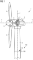
- FIG. 1 shows a wind turbine 1 with a calibration device 100 in accordance with an exemplary embodiment of the present invention.
- the wind turbine 1 comprises a tower 2, which is mounted on a non-depicted fundament.
- a nacelle 3 is arranged on top of the tower 2.
- a yaw angle adjustment device (not shown) is provided, which is capable of rotating the nacelle around a vertical yaw axis Z.
- the wind turbine 1 further comprises a wind rotor 5 having one or more rotational blades 4 (in the perspective of Figure 1 only two blades 4 are visible).
- the wind rotor 5 is rotatable around a rotational axis Y.
- the terms axial, radial and circumferential in the following are made with reference to the rotational axis Y.
- the blades 4 extend radially with respect to the rotational axis Y.
- the wind turbine 1 comprises an electric generator 6 having a stator 11 and a rotor 12.
- the rotor 12 is rotatable with respect to the stator 11 about the rotational axis Y to generate electrical power.
- the electric generator 6 and the generation of electrical power through the present invention is not a specific object of the present invention and therefore not described in further detail.
- FIG. 2 shows a leaky feeder 110 in accordance with an exemplary embodiment of the present invention.
- the leaky feeder 110 is configured as a leaky coaxial cable.
- the center of the leaky feeder is a conductor 116, e.g. a copper cable/wire.
- the conductor 116 is embedded (encapsulated) in a dielectric material layer 117.
- a shielding layer (outer conductor) 118 e.g. a metal/copper layer.
- a plurality of slots (apertures) 112 is formed in said shielding layer 118. Thereby, it is enabled to transmit/receive electromagnetic signal along the length of the leaky feeder 110.
- a protection layer in particular a dielectric such as rubber material, more in particular with low optical coverage, can be arranged around the shielding layer 118.
- the slots 112 are located with predefined positions and distances between each other.
- the first slot 111 is the outermost slot with respect to the input or output of the leaky feeder 110.
- an elongated conductor (not shown in this Figure) can be connected to the leaky feeder 110 in closest proximity to the first slot 111.
- FIG. 3 shows a leaky feeder path 125 in accordance with an exemplary embodiment of the present invention.
- a first leaky feeder 110a is arranged at a wind turbine tower 2 and coupled at its extremities to communication-associated devices 130, in this example between a transmitter 131 and a terminator 133, e.g. a resistor.
- the connection to the transmitter 131 is realized by an elongated conductor 120a that serves as a lead-in cable, while the leaky feeder 110a is connected to the termination 133 by a further elongated conductor 120b that serves as a lead-out cable.
- a further leaky feeder 110b is connected through a lead-in cable 120c to a termination 133 and through a lead-out cable 120d to a receiver 132.
- the transmitter 131 provides an electromagnetic signal through the lead-in cable 120a to the leaky feeder 110a, which transmits said signal along its entire length.
- the transmitted signal is reflected by a blade 4 of the wind turbine 1.
- Said reflected signal is then received by the further leaky feeder 110b at a specific position.
- the further leaky feeder 110b provides the received signal through the lead-out cable 120d to the receiver 132.
- a radar can be realized that can be used to inspect/monitor the wind turbine blade 4.
- FIG. 4 shows a calibration device 100 in accordance with an exemplary embodiment of the present invention.
- the calibration device 100 comprises a leaky feeder 110 with a plurality of slots 112 and slot groups 115.
- a first elongated conductor 120 configured as a lead-in cable, electrically connects the leaky feeder 110 to a transmitter unit 131.
- a second elongated conductor 121 configured as a lead-out cable, connects the leaky feeder 110 to a receiver unit 132.
- the transmitter unit 131 is configured as a pulse generator, configured to transmit an electromagnetic signal, being an incident a pulse (e.g. a rectangular pulse) through the first elongated conductor 120 and the leaky feeder 110.
- the receiver unit 132 is implemented as an analog-to-digital (A/D) converter, configured to receive the incident (direct) pulse after propagation through the elongated conductors 120, 121 and the leaky feeder 110.
- A/D analog-to-digital
- L1 is the length between transmitter 131 and the joint connection 126 between first elongated conductor 120 and leaky feeder 110.
- L2 is the length between the joint connection 126 and the first slot 111 of the leaky feeder 110.
- L3 is the length from the first slot 111 to the receiver 132.
- a (rectangular) pulse will be generated by a pulse generator 131 and is fed into the leaky feeder path 125.
- an analog to digital converter 132 is placed and will be used as receiver.
- the ADC is equipped with a termination resistance 133 with the same value of the wave impedance of the leaky feeder path 125 (cable combination). This might be most for example 50 ohms.
- a single pulse is fed into the path 125, and the ADC 132 is checking, if it can receive the pulse. If it is not possible to receive the pulse, there may be a damage of the cables 125 or joints/connectors 126.
- Figure 5 shows a calibration device 100 in accordance with a further exemplary embodiment of the present invention.
- the set-up is comparable to the one described for Figure 4 with the difference that the receiver unit 132 is not coupled to a lead-out cable 121 (second elongated conductor), but instead (in this example via a T-joint) to the lead-in cable 120 (first elongated conductor).
- the lead-out cable 121 is obsolete and replaced by a termination 133.
- the length L4 can be determined, i.e. the length between the receiver unit 132 and the coupling point (T-joint) to the lead-in cable 120.
- the receiver 132 does not receive the incident electromagnetic signal/pulse, but instead the reflected signal pulse in this configuration.
- the transmitter 131 is connected to one end of the leaky feeder 110, while the other end is terminated.
- the receiver 132 is connected via a T-joint (with an impedance matching network) close to the pulse generator 131, sending a (rectangular) pulse.
- the pulse will be reflected.
- the receiver 132 will see the incident and reflected pulse. If the cable configuration 125 is fine, the receiver 132 will mainly detect the incident pulse, except, reflections on the slots 112 of the leaky feeder 110.
- Joint connection(s) 126 and also slots 112 of the leaky feeder 110 will work as small mismatches of the wave impedance of the cables and therefore also reflect a small part of the pulse energy.
- This principle is established and can be used to determine the length information, e.g. from the pulse generator 131 to the first slot 111. With the length information, it is possible to calculate the phase angle information (phase offset) to shift the phase for a specific needed purpose (e.g. beam steering).
- Figure 6 shows a received reflected pulse in accordance with an exemplary embodiment of the present invention.
- Said pulse is received at the receiver 132 in the example of Figure 5 .
- the termination 133 here a resistor
- quite different reflected pulses a) to e) are received.
- Figure 7 shows voltage and current of pulses over time in accordance with an exemplary embodiment of the present invention.
- the upper scheme shows the voltage (positive and negative values) over time for an incident pulse, a reflected pulse, and a mixture of an incident/reflected pulse.
- the lower scheme shows a current (only positive values) over time for an incident pulse, a reflected pulse, and a mixture of incident/reflected pulse.
- Figure 8 shows the intensity of an incident pulse and a reflected pulse over time in accordance with an exemplary embodiment of the present invention.
- the receiver 132 detects the incident pulse and later-on the reflected pulse with a comparable intensity. This can be the case for an open-cable configuration.
- Figure 9 shows the intensity of an incident pulse and a reflected pulse over time in accordance with an exemplary embodiment of the present invention.
- the receiver 132 detects the incident pulse and later-on the reflected pulse, wherein the later comprises a significantly lower intensity. This can be the case, when the pulse is reflected at the joint connection 126, in particular if a jump of wave impedance is implemented at said joint connection 126.
- a slot 112 of the leaky feeder 110 could provide such a reflected signal.
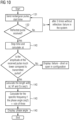
- Figure 10 shows a method of calibrating a leaky feeder path 125, for example according to the configuration of Figure 5 , in accordance with an exemplary embodiment of the present invention.
- a (rectangular) pulse is sent from the transmitter 131.
- the reflected (or incident) pulse is then received by the receiver 132.
- This first step can be applied as a "life" test of the system.
- the time difference between incident and reflected pulse detection can be determined.
- the amplitude (intensity) of the incident pulse should be significantly higher than of the reflected pulse (see Figure 9 ). If this is not the case (see Figure 8 ), there might be a failure, e.g. a short circuit or an open cable.
- a length information can be derived, which could be further used to determine a phase angle information.
- the last steps are performed, as indicated, by a processing device 140.
Landscapes
- Engineering & Computer Science (AREA)
- Life Sciences & Earth Sciences (AREA)
- Sustainable Development (AREA)
- Sustainable Energy (AREA)
- Chemical & Material Sciences (AREA)
- Combustion & Propulsion (AREA)
- Mechanical Engineering (AREA)
- General Engineering & Computer Science (AREA)
- Radar Systems Or Details Thereof (AREA)
- Arrangements For Transmission Of Measured Signals (AREA)
Abstract
There is described a calibration device (100), in particular for a wind turbine (1), comprising:
i) a leaky feeder (110);
ii) an elongated conductor (120), in particular a lead-in and/or a lead-out cable, connected to the leaky feeder (110); iii) a transmitter (131), coupled to the elongated conductor (120), and configured to transmit an electromagnetic signal, in particular a pulse, through the elongated conductor (120) to the leaky feeder (110);
iv) a receiver (132), coupled to the elongated conductor (120) and/or to the leaky feeder (110), and configured to receive the electromagnetic signal directly and/or as a reflection; and
v) a processing device (140), configured to perform a calibration operation based on the reception of the received signal.
i) a leaky feeder (110);
ii) an elongated conductor (120), in particular a lead-in and/or a lead-out cable, connected to the leaky feeder (110); iii) a transmitter (131), coupled to the elongated conductor (120), and configured to transmit an electromagnetic signal, in particular a pulse, through the elongated conductor (120) to the leaky feeder (110);
iv) a receiver (132), coupled to the elongated conductor (120) and/or to the leaky feeder (110), and configured to receive the electromagnetic signal directly and/or as a reflection; and
v) a processing device (140), configured to perform a calibration operation based on the reception of the received signal.
Description
- The present invention relates to a calibration device comprising a leaky feeder. Further, the invention relates to a wind turbine comprising the calibration device. The invention also relates to a method of calibrating a leaky feeder path, and a specific use of time domain reflectometry. Thus, the present invention may relate to the technical field of wind turbines.
- A leaky feeder ("radiating cable") is a cable or waveguide that is "leaky" in that it comprises slots in an outer conductor layer, so that electromagnetic signals leak in and/or out through said slots along the entire length of the leaky feeder or parts of it. Accordingly, a leaky feeder can be especially interesting for applications, where signals should be transmitted/received along an extension, for example a tunnel, a mine, or a train.
- Wind turbines can be considered as an important energy production source and it can be expected that their importance and distribution will grow more and more. Accordingly, there is constant research and development undertaken to further improve the functionality of wind turbines. An important aspect in this regard may be the inspection of the wind turbine blades, in particular during operation. In this respect, a leaky feeder application may be especially useful, for example by monitoring the blade(s) using one or more leaky feeder as antenna(s) of a radar functionality.
- Yet, for some applications of the leaky feeder, a calibration (of the leaky feeder path) may be necessary. In the first place, a calibration should be done as a quality check, if there is a fault, damage or change of the leaky feeder. In further (advanced) applications, it may be required to accurately determine a length information and/or a phase information. In order to determine this information, a calibration of the configuration may be needed.
- Such a calibration may be conventionally done using a signal transfer "over the air" between transmitting/receiving devices, e.g. a radar functionality. Nevertheless, in case of a non-radar application (in particular no reflection of the transmitted signal), no established solution may be at hand.
- There may be a need to calibrate a leaky feeder path (with respect to a wind turbine) in an efficient and reliable manner.
- This need may be met by the subject matter according to the independent claims. Advantageous embodiments of the present invention are described by the dependent claims.
- According to a first aspect of the invention, there is described a calibration device (in particular for a wind turbine), comprising:
- i) a leaky feeder (comprising a plurality of slots, wherein the term "slot" may also include slot groups),
- ii) at least one elongated conductor (in particular a lead-in cable and/or a lead-out cable), (electrically) connected to the leaky feeder,
- iii) a transmitter (unit, e.g. a pulse generator), coupled to the (lead-in) elongated conductor, and configured to transmit an electromagnetic signal (in particular a pulse or a wave) through the elongated conductor (and through) to the leaky feeder,
- iv) a receiver (unit, e.g. an A/D converter), coupled to the (lead-in or lead-out) elongated conductor (and/or to the leaky feeder) and/or configured to receive
- a) the incident (direct, reflection-free) electromagnetic signal and/or
- b) a reflection of the electromagnetic signal, reflected (with)in the at least one elongated conductor and/or the leaky feeder (the leaky feeder path), and
- v) a processing device, configured to perform a calibration operation based on the reception (in particular the detection) of the electromagnetic signal.
- According to a second aspect of the invention, there is described a wind turbine comprising:
- i) a tower,
- ii) a nacelle, coupled to the tower,
- iii) a wind rotor, which is arranged at the nacelle, and which comprises at least one blade (in particular three blades), and
- iv) a calibration device as described above.
- According to a third aspect of the invention, there is described a method of calibrating an elongated conductor to leaky feeder path, in particular for a wind turbine, the method comprising:
- i) transmitting an electromagnetic signal, in particular a pulse, through the elongated conductor to the leaky feeder,
- ii) receiving the incident electromagnetic signal and/or receiving a reflection of the electromagnetic signal, reflected within the at least one elongated conductor and/or the leaky feeder, and
- iii) performing a calibration operation based on the reception of the electromagnetic signal.
- According to a fourth aspect of the invention, there is described a use (method of using) of time domain reflectometry to calibrate (the phase angle of) a conductor-to-leaky-feeder path, in particular in the context of a wind turbine.
- In the context of the present document, the term "leaky feeder" may in particular refer to an elongated structure that is configured as a transmitter and/or receiver of electromagnetic waves/signals, wherein the transmission/reception occurs at specifically defined slots/apertures (leaking). An exemplary embodiment of a leaky feeder is shown in
Figure 3 . The leaky feeder may be configured e.g. as a leaky coaxial cable, a leaky waveguide (in particular suitable at high frequencies), or a leaky stripline. - In an embodiment, the leaky feeder comprises a plurality of slots to allow an electromagnetic signal to leak out of the leaky feeder along its (entire or parts of) length. In a further embodiment, the leaky feeder comprises a plurality of slots to allow an electromagnetic signal to leak into the leaky feeder along its (entire) length. In the present document, the term "slot" may also include slot groups. In an embodiment, the slots/slot groups may be, regularly or irregularly distributed along the length of the leaky feeder.
- In an embodiment, the leaky feeder is coupled/connected to at least one of a transmitter (unit), a receiver (unit), a termination (unit), see e.g. the example of
Figure 4 . Hereby, the leaky feeder may be configured to transmit the signal provided by the transmitter (unit) and/or to provide a received signal to the receiver (unit). - In the context of the present document, the term "elongated conductor" may in particular refer to a conductor with a main extension in one spatial dimension, which is much larger than the extension in the other two spatial dimensions, for example a cable. The elongated conductor may serve as an electric connector between the leaky feeder and a communication-associated device, such as a transmitter, a receiver, or a termination (e.g. resistor with characteristic wave impedance of the leaky feeder). Hereby, the exact length of the elongated conductor may not be known and may have to be calibrated. A leaky feeder path may be defined as a (signal) path through the leaky feeder and the connected elongated conductor.
- In the context of the present document, the term "time domain reflectometry" (TDR) may in particular refer to an established method of investigating a device by observing (reflected) waveforms of electromagnetic signals. For example, TDR is used locate faults or discontinuities in a conductor, connector, printed circuit board, or another electrical path. In case that a conductor is of a uniform impedance and properly terminated, then there may be no reflections and the remaining incident signal will be absorbed at the termination. Instead, if there are characteristic (wave) impedance variations, then (some of) the incident signal may be reflected back to the source.
- In the context of the present document, the term "calibration operation" may in particular refer to any calibration that may be done with respect to a leaky feeder (in the context of a wind turbine). For example, such a calibration may be done regarding at least one slot location of the leaky feeder that can serve to determine a length information. Based on the length information (e.g. length of the elongated conductor or length from a communication-associated device to the leaky feeder (via the elongated conductor), in particular to the first slot), further calibration may be performed, for example phase angle information and/or amplitude information may be determined, and phase shifts may then be calibrated (for specific further applications, e.g. beam steering, blade inspection/monitoring, etc.).
- In the context of the present document, the term "processing device" may in particular refer to any hardware and/or software suitable to perform the above described step of performing a calibration operation (based on the reception of the electromagnetic signal). The processing device may comprise one or more processors. In an example, the processing device may be implemented as one or more processing units in the calibration device or the wind turbine, respectively. In another example, the processing device may be located (at least partially) outside of the wind turbine and operate remotely.
- According to an exemplary embodiment, the invention may be based on the idea that a leaky feeder path (of a wind turbine) may be calibrated in an efficient and reliable manner, based on an approach that applies time domain reflectometry. While conventionally, a calibration is done by directly transmitting a signal into/through the air and then receiving it, e.g. like in radar technology, the time domain reflectometry (TDR) technology enables a calibration operation (e.g. to determine the phase angle and/or perform a self-test of the system) within the leaky feeder itself. This is realized by receiving the incident electromagnetic signal and/or the reflected signal directly within the leaky feeder path, i.e. the transmitted signal does not leave the leaky feeder path (environment). Accordingly, no signal transmission over the air and no radar application may be necessary anymore.
- The invention may thus intentionally not transmit a signal through the air, because in this case additional standards and legal regulations has to be followed. This may increase the technical effort and costs. Further, the system could be more easily interfered by external radio frequency noise. The calibration as part of the invention may be more robust to external radio frequency noise and it may allow to determine a fault in the configuration more reliably.
- According to an embodiment, the calibration operation comprises: deriving a length information. The length information may be determined with respect to the (lead-in) elongated conductor and/or the distance from the transmitter through the elongated conductor to the (first) slot of the leaky feeder with closest proximity to the elongated conductor.
- This may provide the advantage that a versatile length information (potentially required for further calibrations) may be directly derivable. For example, the length of the elongated conductor may be determined or the length from a communication-associated device (via the elongated conductor) to the (first slot of the) leaky feeder.
- In an example, the length from the communication-associated device (e.g. transmitter) to the first slot could be calculated by a time measurement of the incident and reflected electromagnetic pulse:

- According to a further embodiment, the processing device is further configured to derive a phase angle information based on the length information. The phase angle information may be a valuable information for further calibration operations and applications of the leaky feeder (path).
- In an example, the phase angle may be calculated as follows:

- Hereby, n is an integer to be multiplied by 360°, for example in case n = 1.1, the phase angle would be 396°.
- According to a further embodiment, the processing device is further configured to: (detect the incident electromagnetic signal and the reflected electromagnetic signal and) compare the incident electromagnetic signal and the reflected electromagnetic signal. Thereby, valuable calibration information may be obtained in an efficient manner.
- According to a further embodiment, the transmitter comprises a pulse generator, in particular wherein the electromagnetic signal comprises a rectangular pulse. This may provide the advantage that an established and accurate means can be implemented in a straightforward manner as a transmitter (unit). Besides a pulse, also a wave may be provided. In an example, the pulse shape is not limited to rectangular.
- According to a further embodiment, the receiver comprises an analog-to-digital converter, ADC. This may also provide the advantage that an established and accurate means can be implemented in a straightforward manner as a receiver (unit). Using the ADC, the received analog signal is directly converted to a digital signal that can be further processed. Thereby, additional effort may be saved.
- According to a further embodiment, the at least one elongated conductor comprises a further elongated conductor (lead-out cable), connected between the leaky feeder and the receiver. This configuration (see e.g.
Figure 4 ) may be especially suitable to detect an incident signal. - According to a further embodiment, the calibration device further comprises: a termination (e.g. a resistor), connected to the leaky feeder. In this configuration (see e.g.
Figure 5 ), no further elongated conductor (lead-out cable) may be necessary. Thus, configuration may be especially suitable to detect a reflected signal. - According to a further embodiment, the at least one elongated conductor comprises a resistance or impedance (in particular wave impedance) different from the resistance or impedance (in particular wave impedance) of the leaky feeder, to thereby enable a reflection of the electromagnetic signal at the resistance or impedance mismatch. Such a mismatch caused by different resistance/impedance may cause a characteristic reflection at the interface between elongated conductor and leaky feeder.
- In an example, there are two different characteristic wave impedances by design. For a leaky feeder, the impedance may be for example around 50 ohms. By designing a lead-in cable with a mismatch of the wave impendence, it may be possible to create a wanted reflection at the joint connection of the lead-in cable to the leaky feeder. This could be for example a 57 ohms wave impedance for the lead-in cable. This will cause a reflection of the calibration pulse at the joint connection of the lead-in cable to the leaky feeder, and therefore allow to estimate the length of the lead-in cable.
- According to a further embodiment, the calibration device comprises a (mechanical/electrical) mismatch at the joint connection (interface) between the at least one elongated conductor and the leaky feeder, to thereby enable a reflection of the electromagnetic signal at the joint connection. Such an intentionally formed mismatch may cause a characteristic reflection at the interface between elongated conductor and leaky feeder.
- In an example, a wanted mismatch in the characteristic wave impedance of the lead-in cable of the leaky feeder (and/or in the joint or leaky feeder itself) is provided. The joint of leaky feeder and the lead-in cable may cause a jump in the wave impedance and may therefore reflect a small part of the pulse. With this reflected pulse, it may be possible to determine the length information, e.g. of the lead-in cable.
- According to a further embodiment, the electromagnetic signal is reflected at a slot (in particular the slot with closest proximity to the elongated conductor) of the leaky feeder. The slot may hereby function as an impedance to reflect a part of the incident signal. This may provide the advantage that the inherent structure of the leaky feeder can be directly used to obtain a reflection without further effort. Hereby, the position of the slot may be precisely determined and serve for determining the length information. In an example, a plurality of reflections are caused by the plurality of slots.
- According to a further embodiment, the leaky feeder is at least partially located in the tower circumferential direction, in particular (bent) inside or outside of the tower. Thereby, the length extension of the leaky feeder may be exploited in an advantageous manner.
- According to a further embodiment, the processing device is further configured to apply the phase angle information to calibrate a phase shift of a leaky feeder transmitted electromagnetic signal, in particular adapt the phase shift of two or more leaky feeder transmitted electromagnetic signals, e.g. to steer an electromagnetic signal beam, for example to thereby inspect/monitor a wind turbine blade.
- According to a further embodiment, the method further comprising: determining a length information (with respect to the leaky feeder path) based on the received electromagnetic signal, in particular further comprising: deriving a phase angle information from the length information.
- In an embodiment, the phase (angle) information may be important for advanced measurement setups, for example beam forming/steering with multiple leaky feeders parallel and/or close together.
- In an embodiment, a calibration may be required to determine a length information, e.g. from the transmitter to the first slot/slot group, and to calculate with the length information the phase information. Furthermore, a "life" test of the system can be performed to detect faults like damages or moisture associated with the leaky feeder.
- In an embodiment, a pulse includes multiple waves (then Fourier analysis may be performed). The term "electromagnetic waves" may hence include pulses (as a special kind of wave).
- In an embodiment, a direct connection of the transmitter/receiver unit to the leaky feeder (without an elongated conductor in between) is established.
- The aspects defined above and further aspects of the present invention are apparent from the examples of embodiment to be described hereinafter and are explained with reference to the examples of embodiment. The invention will be described in more detail hereinafter with reference to examples of embodiment but to which the invention is not limited.
-
-
Figure 1 shows a wind turbine with a calibration device in accordance with an exemplary embodiment of the present invention. -
Figure 2 shows a leaky feeder in accordance with an exemplary embodiment of the present invention. -
Figure 3 shows a leaky feeder path in accordance with an exemplary embodiment of the present invention. -
Figure 4 shows a calibration device in accordance with an exemplary embodiment of the present invention. -
Figure 5 shows a calibration device in accordance with a further exemplary embodiment of the present invention. -
Figure 6 shows a reflected pulse in accordance with an exemplary embodiment of the present invention. -
Figure 7 shows voltage and current of pulses over time in accordance with an exemplary embodiment of the present invention. -
Figure 8 shows an incident pulse and a reflected pulse in accordance with an exemplary embodiment of the present invention. -
Figure 9 shows an incident pulse and a reflected pulse in accordance with a further exemplary embodiment of the present invention. -
Figure 10 shows a method of calibrating a leaky feeder path in accordance with an exemplary embodiment of the present invention. - The illustration in the drawing is schematic. It is noted that in different figures, similar or identical elements or features are provided with the same reference signs or with reference signs, which are different from the corresponding reference signs only within the first digit. In order to avoid unnecessary repetitions elements or features which have already been elucidated with respect to a previously described embodiment are not elucidated again at a later position of the description.
- Further, spatially relative terms, such as "front" and "back", "above" and "below", "left" and "right", et cetera are used to describe an element's relationship to another element(s) as illustrated in the figures. Thus, the spatially relative terms may apply to orientations in use which differ from the orientation depicted in the figures. Obviously all such spatially relative terms refer to the orientation shown in the figures only for ease of description and are not necessarily limiting as an apparatus according to an embodiment of the invention can assume orientations different than those illustrated in the figures when in use.
-
Figure 1 shows a wind turbine 1 with acalibration device 100 in accordance with an exemplary embodiment of the present invention. The wind turbine 1 comprises atower 2, which is mounted on a non-depicted fundament. Anacelle 3 is arranged on top of thetower 2. In between thetower 2 and thenacelle 3, a yaw angle adjustment device (not shown) is provided, which is capable of rotating the nacelle around a vertical yaw axis Z. - The wind turbine 1 further comprises a wind rotor 5 having one or more rotational blades 4 (in the perspective of
Figure 1 only two blades 4 are visible). The wind rotor 5 is rotatable around a rotational axis Y. In general, when not differently specified, the terms axial, radial and circumferential in the following are made with reference to the rotational axis Y. - The blades 4 extend radially with respect to the rotational axis Y. The wind turbine 1 comprises an electric generator 6 having a stator 11 and a rotor 12. The rotor 12 is rotatable with respect to the stator 11 about the rotational axis Y to generate electrical power. The electric generator 6 and the generation of electrical power through the present invention is not a specific object of the present invention and therefore not described in further detail.
-
Figure 2 shows aleaky feeder 110 in accordance with an exemplary embodiment of the present invention. In this example, theleaky feeder 110 is configured as a leaky coaxial cable. The center of the leaky feeder is aconductor 116, e.g. a copper cable/wire. Theconductor 116 is embedded (encapsulated) in adielectric material layer 117. Further, around thedielectric material layer 117, there is arranged a shielding layer (outer conductor) 118, e.g. a metal/copper layer. A plurality of slots (apertures) 112 is formed in saidshielding layer 118. Thereby, it is enabled to transmit/receive electromagnetic signal along the length of theleaky feeder 110. Since the transmission/reception takes (essentially) only place at the slots, it is termed "leaking". Optionally, a protection layer (cable jacket), in particular a dielectric such as rubber material, more in particular with low optical coverage, can be arranged around theshielding layer 118. Theslots 112 are located with predefined positions and distances between each other. Thefirst slot 111 is the outermost slot with respect to the input or output of theleaky feeder 110. - For example, an elongated conductor (not shown in this Figure) can be connected to the
leaky feeder 110 in closest proximity to thefirst slot 111. -
Figure 3 shows aleaky feeder path 125 in accordance with an exemplary embodiment of the present invention. A firstleaky feeder 110a is arranged at awind turbine tower 2 and coupled at its extremities to communication-associateddevices 130, in this example between atransmitter 131 and aterminator 133, e.g. a resistor. The connection to thetransmitter 131 is realized by anelongated conductor 120a that serves as a lead-in cable, while theleaky feeder 110a is connected to thetermination 133 by a furtherelongated conductor 120b that serves as a lead-out cable. In a comparable manner, a furtherleaky feeder 110b is connected through a lead-incable 120c to atermination 133 and through a lead-outcable 120d to areceiver 132. - The
transmitter 131 provides an electromagnetic signal through the lead-incable 120a to theleaky feeder 110a, which transmits said signal along its entire length. In this specific example, the transmitted signal is reflected by a blade 4 of the wind turbine 1. Said reflected signal is then received by the furtherleaky feeder 110b at a specific position. The furtherleaky feeder 110b provides the received signal through the lead-outcable 120d to thereceiver 132. In this configuration, a radar can be realized that can be used to inspect/monitor the wind turbine blade 4. -
Figure 4 shows acalibration device 100 in accordance with an exemplary embodiment of the present invention. Thecalibration device 100 comprises aleaky feeder 110 with a plurality ofslots 112 andslot groups 115. A firstelongated conductor 120, configured as a lead-in cable, electrically connects theleaky feeder 110 to atransmitter unit 131. A secondelongated conductor 121, configured as a lead-out cable, connects theleaky feeder 110 to areceiver unit 132. - The
transmitter unit 131 is configured as a pulse generator, configured to transmit an electromagnetic signal, being an incident a pulse (e.g. a rectangular pulse) through the firstelongated conductor 120 and theleaky feeder 110. Thereceiver unit 132 is implemented as an analog-to-digital (A/D) converter, configured to receive the incident (direct) pulse after propagation through theelongated conductors leaky feeder 110. - Three distances L1, L2, L3 are indicated, which can be determined with the illustrated set-up. L1 is the length between
transmitter 131 and thejoint connection 126 between firstelongated conductor 120 andleaky feeder 110. L2 is the length between thejoint connection 126 and thefirst slot 111 of theleaky feeder 110. L3 is the length from thefirst slot 111 to thereceiver 132. - With this set-up, a check of the
leaky feeder 110 is possible. A (rectangular) pulse will be generated by apulse generator 131 and is fed into theleaky feeder path 125. At the other end of the cable configuration, an analog todigital converter 132 is placed and will be used as receiver. The ADC is equipped with atermination resistance 133 with the same value of the wave impedance of the leaky feeder path 125 (cable combination). This might be most for example 50 ohms. To perform a simple "life" test, a single pulse is fed into thepath 125, and theADC 132 is checking, if it can receive the pulse. If it is not possible to receive the pulse, there may be a damage of thecables 125 or joints/connectors 126. -
Figure 5 shows acalibration device 100 in accordance with a further exemplary embodiment of the present invention. The set-up is comparable to the one described forFigure 4 with the difference that thereceiver unit 132 is not coupled to a lead-out cable 121 (second elongated conductor), but instead (in this example via a T-joint) to the lead-in cable 120 (first elongated conductor). In this configuration, the lead-outcable 121 is obsolete and replaced by atermination 133. - Instead of L3, the length L4 can be determined, i.e. the length between the
receiver unit 132 and the coupling point (T-joint) to the lead-incable 120. - In comparison to the example of
Figure 4 , thereceiver 132 does not receive the incident electromagnetic signal/pulse, but instead the reflected signal pulse in this configuration. - Here, the
transmitter 131 is connected to one end of theleaky feeder 110, while the other end is terminated. Thereceiver 132 is connected via a T-joint (with an impedance matching network) close to thepulse generator 131, sending a (rectangular) pulse. In case there is an open or short in thecable configuration 125, the pulse will be reflected. Thereceiver 132 will see the incident and reflected pulse. If thecable configuration 125 is fine, thereceiver 132 will mainly detect the incident pulse, except, reflections on theslots 112 of theleaky feeder 110. - Joint connection(s) 126 and also
slots 112 of theleaky feeder 110 will work as small mismatches of the wave impedance of the cables and therefore also reflect a small part of the pulse energy. This principle is established and can be used to determine the length information, e.g. from thepulse generator 131 to thefirst slot 111. With the length information, it is possible to calculate the phase angle information (phase offset) to shift the phase for a specific needed purpose (e.g. beam steering). -
Figure 6 shows a received reflected pulse in accordance with an exemplary embodiment of the present invention. Said pulse is received at thereceiver 132 in the example ofFigure 5 . Depending on the resistance of the termination 133 (here a resistor), quite different reflected pulses a) to e) are received. -
Figure 7 shows voltage and current of pulses over time in accordance with an exemplary embodiment of the present invention. The upper scheme shows the voltage (positive and negative values) over time for an incident pulse, a reflected pulse, and a mixture of an incident/reflected pulse. The lower scheme shows a current (only positive values) over time for an incident pulse, a reflected pulse, and a mixture of incident/reflected pulse. -
Figure 8 shows the intensity of an incident pulse and a reflected pulse over time in accordance with an exemplary embodiment of the present invention. Thereceiver 132 detects the incident pulse and later-on the reflected pulse with a comparable intensity. This can be the case for an open-cable configuration. -
Figure 9 shows the intensity of an incident pulse and a reflected pulse over time in accordance with an exemplary embodiment of the present invention. Thereceiver 132 detects the incident pulse and later-on the reflected pulse, wherein the later comprises a significantly lower intensity. This can be the case, when the pulse is reflected at thejoint connection 126, in particular if a jump of wave impedance is implemented at saidjoint connection 126. Alternatively, aslot 112 of theleaky feeder 110 could provide such a reflected signal. -
Figure 10 shows a method of calibrating aleaky feeder path 125, for example according to the configuration ofFigure 5 , in accordance with an exemplary embodiment of the present invention. In the first place, a (rectangular) pulse is sent from thetransmitter 131. The reflected (or incident) pulse is then received by thereceiver 132. This first step can be applied as a "life" test of the system. Afterwards, the time difference between incident and reflected pulse detection can be determined. The amplitude (intensity) of the incident pulse should be significantly higher than of the reflected pulse (seeFigure 9 ). If this is not the case (seeFigure 8 ), there might be a failure, e.g. a short circuit or an open cable. - From the time difference, a length information can be derived, which could be further used to determine a phase angle information. The last steps are performed, as indicated, by a
processing device 140. - It should be noted that the term "comprising" does not exclude other elements or steps, and the use of the item "a" does not exclude multiplicity. Elements described in conjunction with various embodiments can also be combined. It should also be noted that reference signs in the claims should not be interpreted as limiting the scope of the claims.
- Independent of the grammatical term usage, individuals with male, female or other gender identities are included within the term.
Claims (15)
- A calibration device (100), in particular for a wind turbine (1), comprising:a leaky feeder (110);at least one elongated conductor (120, 121), in particular a lead-in (120) and/or a lead-out cable (121), connected to the leaky feeder (110);a transmitter (131), coupled to the at least one elongated conductor (120), and configured to transmit an electromagnetic signal, in particular a pulse, through the at least one elongated conductor (120) to the leaky feeder (110);a receiver (132), coupled to the at least one elongated conductor (120, 121), and configured to receive the incident electromagnetic signal and/or
a reflection of the electromagnetic signal, reflected in the at least one elongated conductor (120, 121) and/or the leaky feeder (110); anda processing device (140), configured to perform a calibration operation based on the reception of the electromagnetic signal. - The calibration device (100) according to claim 1, wherein the calibration operation comprises:deriving a length information,in particular with respect to:the at least one elongated conductor (120), and/orthe distance from the transmitter (131) through the elongated conductor (120) to the slot (111) of the leaky feeder (110) with closest proximity to the elongated conductor (120).
- The calibration device (100) according to claim 2, wherein the processing device (140) is further configured to:
derive a phase angle information and/or an amplitude information based on the length information. - The calibration device (100) according to any one of the preceding claims, wherein the processing device (140) is further configured to:
compare the incident electromagnetic signal and the reflected electromagnetic signal. - The calibration device (100) according to any one of the preceding claims,wherein the transmitter (131) comprises a pulse generator, in particular wherein the electromagnetic signal comprises a pulse; and/orwherein the receiver (132) comprises an analog-to-digital converter, ADC.
- The calibration device (100) according to any one of the preceding claims, further comprising:wherein the at least one elongated conductor (120, 121) comprises a further elongated conductor (121), connected between the leaky feeder (110) and the receiver (132); ora termination (133), connected to the leaky feeder (110) .
- The calibration device (100) according to any one of the preceding claims,
wherein the at least one elongated conductor (120) comprises a resistance or impedance, in particular wave impedance, different from the resistance or impedance, in particular wave impedance, of the leaky feeder (110), to thereby enable a reflection of the electromagnetic signal at the resistance or impedance mismatch. - The calibration device (100) according to any one of the preceding claims,
comprising a mismatch at the joint connection (126) between the at least one elongated conductor (120) and the leaky feeder (110), to thereby enable a reflection of the electromagnetic signal at the joint connection (126). - The calibration device (100) according to any one of the preceding claims,
wherein the electromagnetic signal is reflected at a slot (112), in particular the slot (111) with closest proximity to the elongated conductor (120), of the leaky feeder (110). - The calibration device (100) according to any one of preceding claims 3 to 9,
wherein the processing device (140) is further configured to:apply the phase angle information to calibrate a phase shift of a leaky feeder (110) transmitted electromagnetic signal, in particularadapt the phase shift of two or more leaky feeder (110) transmitted electromagnetic signals, to steer an electromagnetic signal beam,more in particular to thereby inspect a wind turbine blade (4) . - A wind turbine (1) comprising:a tower (2);a nacelle (3), coupled to the tower (1);a wind rotor (5), which is arranged at the nacelle (3), and which comprises at least one blade (4); anda calibration device (100) according to any one of the preceding claims.
- The wind turbine (1) according to claim 11,
wherein the leaky feeder (110) is at least partially located in the tower circumferential direction, in particular inside or outside of the tower (2). - A method of calibrating a leaky feeder path (125), comprising an elongated conductor (120) connected to a leaky feeder (110), in particular for a wind turbine (1), the method comprising:transmitting an electromagnetic signal, in particular a pulse, through the elongated conductor (120) to the leaky feeder (110);receiving the incident electromagnetic signal and/or receiving a reflection of the electromagnetic signal, reflected in the elongated conductor (120) and/or the leaky feeder (110); andperforming a calibration operation based on the reception of the electromagnetic signal.
- The method according to claim 13, wherein performing the calibration operation further comprises:deriving a length information from the received electromagnetic signal; andderiving a phase angle information from the length information.
- Using time domain reflectometry to calibrate a conductor-to-leaky-feeder (115) path, in particular in the context of a wind turbine (1).
Priority Applications (2)
| Application Number | Priority Date | Filing Date | Title |
|---|---|---|---|
| EP23161381.1A EP4432471A1 (en) | 2023-03-13 | 2023-03-13 | Calibration device for leaky feeder time domain reflectometry, and wind turbine |
| PCT/EP2023/083335 WO2024188486A1 (en) | 2023-03-13 | 2023-11-28 | Calibration device for leaky feeder time domain reflectometry, and wind turbine |
Applications Claiming Priority (1)
| Application Number | Priority Date | Filing Date | Title |
|---|---|---|---|
| EP23161381.1A EP4432471A1 (en) | 2023-03-13 | 2023-03-13 | Calibration device for leaky feeder time domain reflectometry, and wind turbine |
Publications (1)
| Publication Number | Publication Date |
|---|---|
| EP4432471A1 true EP4432471A1 (en) | 2024-09-18 |
Family
ID=85571330
Family Applications (1)
| Application Number | Title | Priority Date | Filing Date |
|---|---|---|---|
| EP23161381.1A Pending EP4432471A1 (en) | 2023-03-13 | 2023-03-13 | Calibration device for leaky feeder time domain reflectometry, and wind turbine |
Country Status (2)
| Country | Link |
|---|---|
| EP (1) | EP4432471A1 (en) |
| WO (1) | WO2024188486A1 (en) |
Citations (4)
| Publication number | Priority date | Publication date | Assignee | Title |
|---|---|---|---|---|
| FR3059780A1 (en) * | 2016-12-01 | 2018-06-08 | Electricite De France | METHOD AND SYSTEM FOR MONITORING A CIVIL ENGINEERING WORK |
| EP3626965A1 (en) * | 2018-09-21 | 2020-03-25 | Siemens Gamesa Renewable Energy A/S | Object position and/or speed and/or size and/or direction detection device for a wind turbine |
| US20200412003A1 (en) * | 2019-06-26 | 2020-12-31 | Ohio State Innovation Foundation | Proximity sensor using a leaky coaxial cable |
| US20220333969A1 (en) * | 2021-04-14 | 2022-10-20 | Welldata (Subsurface Surveillance Systems) Limited | Fluid detection |
-
2023
- 2023-03-13 EP EP23161381.1A patent/EP4432471A1/en active Pending
- 2023-11-28 WO PCT/EP2023/083335 patent/WO2024188486A1/en not_active Ceased
Patent Citations (4)
| Publication number | Priority date | Publication date | Assignee | Title |
|---|---|---|---|---|
| FR3059780A1 (en) * | 2016-12-01 | 2018-06-08 | Electricite De France | METHOD AND SYSTEM FOR MONITORING A CIVIL ENGINEERING WORK |
| EP3626965A1 (en) * | 2018-09-21 | 2020-03-25 | Siemens Gamesa Renewable Energy A/S | Object position and/or speed and/or size and/or direction detection device for a wind turbine |
| US20200412003A1 (en) * | 2019-06-26 | 2020-12-31 | Ohio State Innovation Foundation | Proximity sensor using a leaky coaxial cable |
| US20220333969A1 (en) * | 2021-04-14 | 2022-10-20 | Welldata (Subsurface Surveillance Systems) Limited | Fluid detection |
Also Published As
| Publication number | Publication date |
|---|---|
| WO2024188486A1 (en) | 2024-09-19 |
Similar Documents
| Publication | Publication Date | Title |
|---|---|---|
| US20200182906A1 (en) | Sensor device, water amount measurement device, water amount measurement method, information processing device, and information processing method | |
| US7915898B1 (en) | Integrated cable/connector shielding surveillance system | |
| CN109932614A (en) | A kind of cable fault investigation method and device | |
| CN104931799A (en) | On-chip antenna electrical property test system and method | |
| US20220178785A1 (en) | Method and apparatus for performing measurements and monitoring of an object | |
| CN113614366A (en) | Distributed system and method for detecting position and/or speed of rotor blades during operation of a wind turbine | |
| US20130033270A1 (en) | Electromagnetic interference test sytem with self-checking function and self-checking method | |
| US11988193B2 (en) | Device for a wind turbine | |
| EP3719528A1 (en) | Detecting properties of a moving object at a wind turbine site using a beam forming arrangement of leaky feeders | |
| US20240352922A1 (en) | Lightning protection system evaluation based on impedance analysis | |
| US12066478B2 (en) | Fault detecting system for coaxial transmission lines | |
| CN110412370A (en) | Multi-coaxial cable assembly shield effectiveness detection method based on radiation method | |
| WO2024188486A1 (en) | Calibration device for leaky feeder time domain reflectometry, and wind turbine | |
| EP4431731A1 (en) | Calibration device for leaky feeder frequency domain reflectometry, and wind turbine | |
| Sinai et al. | Multi-Physical sensor fusion approach for partial discharge detection on medium voltage cable connectors | |
| WO2021261193A1 (en) | Current measurement component, current measurement device, and current measurement method | |
| EP4431733A1 (en) | Wind turbine comprising a leaky feeder based inverse synthetic aperture radar, and method | |
| CN208028916U (en) | Cable Operation Monitoring System | |
| CN215953739U (en) | Accuracy verification device for current method conducted disturbance measurement system | |
| WO2011081526A1 (en) | Method and system for detecting faults in laminated structures | |
| CN114545159B (en) | Cable defect detection system and method | |
| CN113504417B (en) | An accuracy verification device for current method conducted disturbance measurement system | |
| CN113614361A (en) | Electromagnetic measurement for wind turbines | |
| EP4431732A1 (en) | Wind turbine with leaky feeder based beam steering, and method of calibration | |
| TW201940890A (en) | Cable operation detecting system including a cable and a cable operation detecting device |
Legal Events
| Date | Code | Title | Description |
|---|---|---|---|
| PUAI | Public reference made under article 153(3) epc to a published international application that has entered the european phase |
Free format text: ORIGINAL CODE: 0009012 |
|
| STAA | Information on the status of an ep patent application or granted ep patent |
Free format text: STATUS: THE APPLICATION HAS BEEN PUBLISHED |
|
| AK | Designated contracting states |
Kind code of ref document: A1 Designated state(s): AL AT BE BG CH CY CZ DE DK EE ES FI FR GB GR HR HU IE IS IT LI LT LU LV MC ME MK MT NL NO PL PT RO RS SE SI SK SM TR |