EP4432420A1 - Cell monitoring apparatus and battery pack including the apparatus - Google Patents
Cell monitoring apparatus and battery pack including the apparatus Download PDFInfo
- Publication number
- EP4432420A1 EP4432420A1 EP23181584.6A EP23181584A EP4432420A1 EP 4432420 A1 EP4432420 A1 EP 4432420A1 EP 23181584 A EP23181584 A EP 23181584A EP 4432420 A1 EP4432420 A1 EP 4432420A1
- Authority
- EP
- European Patent Office
- Prior art keywords
- cell
- vent hole
- resistor
- monitoring apparatus
- missing
- Prior art date
- Legal status (The legal status is an assumption and is not a legal conclusion. Google has not performed a legal analysis and makes no representation as to the accuracy of the status listed.)
- Pending
Links
Images

Classifications
-
- H—ELECTRICITY
- H01—ELECTRIC ELEMENTS
- H01M—PROCESSES OR MEANS, e.g. BATTERIES, FOR THE DIRECT CONVERSION OF CHEMICAL ENERGY INTO ELECTRICAL ENERGY
- H01M10/00—Secondary cells; Manufacture thereof
- H01M10/42—Methods or arrangements for servicing or maintenance of secondary cells or secondary half-cells
- H01M10/48—Accumulators combined with arrangements for measuring, testing or indicating the condition of cells, e.g. the level or density of the electrolyte
-
- G—PHYSICS
- G08—SIGNALLING
- G08B—SIGNALLING SYSTEMS, e.g. PERSONAL CALLING SYSTEMS; ORDER TELEGRAPHS; ALARM SYSTEMS
- G08B21/00—Alarms responsive to a single specified undesired or abnormal condition and not otherwise provided for
- G08B21/18—Status alarms
-
- H—ELECTRICITY
- H01—ELECTRIC ELEMENTS
- H01M—PROCESSES OR MEANS, e.g. BATTERIES, FOR THE DIRECT CONVERSION OF CHEMICAL ENERGY INTO ELECTRICAL ENERGY
- H01M10/00—Secondary cells; Manufacture thereof
- H01M10/42—Methods or arrangements for servicing or maintenance of secondary cells or secondary half-cells
- H01M10/425—Structural combination with electronic components, e.g. electronic circuits integrated to the outside of the casing
-
- H—ELECTRICITY
- H01—ELECTRIC ELEMENTS
- H01M—PROCESSES OR MEANS, e.g. BATTERIES, FOR THE DIRECT CONVERSION OF CHEMICAL ENERGY INTO ELECTRICAL ENERGY
- H01M10/00—Secondary cells; Manufacture thereof
- H01M10/42—Methods or arrangements for servicing or maintenance of secondary cells or secondary half-cells
- H01M10/48—Accumulators combined with arrangements for measuring, testing or indicating the condition of cells, e.g. the level or density of the electrolyte
- H01M10/482—Accumulators combined with arrangements for measuring, testing or indicating the condition of cells, e.g. the level or density of the electrolyte for several batteries or cells simultaneously or sequentially
-
- H—ELECTRICITY
- H01—ELECTRIC ELEMENTS
- H01M—PROCESSES OR MEANS, e.g. BATTERIES, FOR THE DIRECT CONVERSION OF CHEMICAL ENERGY INTO ELECTRICAL ENERGY
- H01M50/00—Constructional details or processes of manufacture of the non-active parts of electrochemical cells other than fuel cells, e.g. hybrid cells
- H01M50/10—Primary casings; Jackets or wrappings
- H01M50/102—Primary casings; Jackets or wrappings characterised by their shape or physical structure
- H01M50/103—Primary casings; Jackets or wrappings characterised by their shape or physical structure prismatic or rectangular
-
- H—ELECTRICITY
- H01—ELECTRIC ELEMENTS
- H01M—PROCESSES OR MEANS, e.g. BATTERIES, FOR THE DIRECT CONVERSION OF CHEMICAL ENERGY INTO ELECTRICAL ENERGY
- H01M50/00—Constructional details or processes of manufacture of the non-active parts of electrochemical cells other than fuel cells, e.g. hybrid cells
- H01M50/30—Arrangements for facilitating escape of gases
-
- H—ELECTRICITY
- H01—ELECTRIC ELEMENTS
- H01M—PROCESSES OR MEANS, e.g. BATTERIES, FOR THE DIRECT CONVERSION OF CHEMICAL ENERGY INTO ELECTRICAL ENERGY
- H01M50/00—Constructional details or processes of manufacture of the non-active parts of electrochemical cells other than fuel cells, e.g. hybrid cells
- H01M50/50—Current conducting connections for cells or batteries
- H01M50/572—Means for preventing undesired use or discharge
- H01M50/574—Devices or arrangements for the interruption of current
- H01M50/581—Devices or arrangements for the interruption of current in response to temperature
-
- H—ELECTRICITY
- H01—ELECTRIC ELEMENTS
- H01M—PROCESSES OR MEANS, e.g. BATTERIES, FOR THE DIRECT CONVERSION OF CHEMICAL ENERGY INTO ELECTRICAL ENERGY
- H01M10/00—Secondary cells; Manufacture thereof
- H01M10/42—Methods or arrangements for servicing or maintenance of secondary cells or secondary half-cells
- H01M10/44—Methods for charging or discharging
-
- H—ELECTRICITY
- H01—ELECTRIC ELEMENTS
- H01M—PROCESSES OR MEANS, e.g. BATTERIES, FOR THE DIRECT CONVERSION OF CHEMICAL ENERGY INTO ELECTRICAL ENERGY
- H01M50/00—Constructional details or processes of manufacture of the non-active parts of electrochemical cells other than fuel cells, e.g. hybrid cells
- H01M50/20—Mountings; Secondary casings or frames; Racks, modules or packs; Suspension devices; Shock absorbers; Transport or carrying devices; Holders
- H01M50/204—Racks, modules or packs for multiple batteries or multiple cells
- H01M50/207—Racks, modules or packs for multiple batteries or multiple cells characterised by their shape
- H01M50/209—Racks, modules or packs for multiple batteries or multiple cells characterised by their shape adapted for prismatic or rectangular cells
-
- H—ELECTRICITY
- H01—ELECTRIC ELEMENTS
- H01M—PROCESSES OR MEANS, e.g. BATTERIES, FOR THE DIRECT CONVERSION OF CHEMICAL ENERGY INTO ELECTRICAL ENERGY
- H01M50/00—Constructional details or processes of manufacture of the non-active parts of electrochemical cells other than fuel cells, e.g. hybrid cells
- H01M50/20—Mountings; Secondary casings or frames; Racks, modules or packs; Suspension devices; Shock absorbers; Transport or carrying devices; Holders
- H01M50/284—Mountings; Secondary casings or frames; Racks, modules or packs; Suspension devices; Shock absorbers; Transport or carrying devices; Holders with incorporated circuit boards, e.g. printed circuit boards [PCB]
-
- H—ELECTRICITY
- H01—ELECTRIC ELEMENTS
- H01M—PROCESSES OR MEANS, e.g. BATTERIES, FOR THE DIRECT CONVERSION OF CHEMICAL ENERGY INTO ELECTRICAL ENERGY
- H01M50/00—Constructional details or processes of manufacture of the non-active parts of electrochemical cells other than fuel cells, e.g. hybrid cells
- H01M50/30—Arrangements for facilitating escape of gases
- H01M50/342—Non-re-sealable arrangements
- H01M50/3425—Non-re-sealable arrangements in the form of rupturable membranes or weakened parts, e.g. pierced with the aid of a sharp member
-
- Y—GENERAL TAGGING OF NEW TECHNOLOGICAL DEVELOPMENTS; GENERAL TAGGING OF CROSS-SECTIONAL TECHNOLOGIES SPANNING OVER SEVERAL SECTIONS OF THE IPC; TECHNICAL SUBJECTS COVERED BY FORMER USPC CROSS-REFERENCE ART COLLECTIONS [XRACs] AND DIGESTS
- Y02—TECHNOLOGIES OR APPLICATIONS FOR MITIGATION OR ADAPTATION AGAINST CLIMATE CHANGE
- Y02E—REDUCTION OF GREENHOUSE GAS [GHG] EMISSIONS, RELATED TO ENERGY GENERATION, TRANSMISSION OR DISTRIBUTION
- Y02E60/00—Enabling technologies; Technologies with a potential or indirect contribution to GHG emissions mitigation
- Y02E60/10—Energy storage using batteries
Definitions
- the present disclosure relates to a cell monitoring apparatus and a battery pack including the apparatus.
- a method of monitoring temperature in a battery module and voltages of battery cells or a method using a pressure sensor is mainly used.
- thermal runaway diagnosis method makes it difficult to clearly identify which battery cell started thermal runaway or how thermal propagation progressed.
- At least one of the embodiments is to provide a cell monitoring apparatus capable of detecting a battery cell in which thermal runaway has occurred and a battery pack including the apparatus.
- a cell monitoring apparatus includes: a plurality of vent hole opening detectors that are located in correspondence with each of a plurality of cells, includes a plurality of missing holes formed corresponding to the position of the vent hole of the corresponding cell, and detects whether or not the vent hole formed in each of the plurality of cells is open using the plurality of missing holes; and a controller that detects a cell in which an event has occurred based on whether a vent hole formed in each of the plurality of cells is open.
- Each of the plurality of vent hole opening detectors may include a first resistor and a second resistor connected in series between a power terminal supplying a power voltage and the ground, and having a contact point connected to the controller, and the first resistor or the second resistor may be located in an area where the plurality of missing holes are located, or a first metal wiring pattern for connection with the first resistor or a second metal wiring pattern for connection with the second resistor may be located in an area where the plurality of missing holes are located.
- the controller may determine the opening of the vent hole from the voltage of the contact point, and determine a cell in which the event has occurred from the opening of the vent hole.
- the plurality of missing holes may be formed at set intervals along the circumference of the vent hole.
- the event may include thermal runaway.
- a battery pack includes: a plurality of cells each formed with a plurality of vent holes; and a cell monitoring apparatus that detects whether the vent hole of each cell is open using a plurality of missing holes formed corresponding to the location of the vent hole of each cell, and detects a cell in which an event has occurred based on whether each cell is open.
- the plurality of missing holes may be formed at set intervals along the circumference of the vent hole.
- the cell monitoring apparatus may include a plurality of vent hole opening detectors for detecting whether a vent hole formed in each of the plurality of cells is open using the plurality of missing holes, each of the plurality of vent hole opening detectors may include a first resistor and a second resistor connected in series between a power terminal supplying a power voltage and a ground, and the first resistor or the second resistor may be located in an area where the plurality of missing holes are located, or a first metal wiring pattern for connection with the first resistor or a second metal wiring pattern for connection with the second resistor may be located in an area where the plurality of missing holes are located.
- the cell monitoring apparatus further may further include a controller for determining whether the vent hole is open based on the voltage of the contact point.
- a resistor located in an area where the plurality of missing holes are located or a resistor connected to a metal wiring pattern located in an area where the plurality of missing holes are located may be opened if an event of a corresponding cell occurs.
- first, second, etc. may be used to describe various elements, but the elements are not limited by the terms. The above terms are used only for the purpose of distinguishing one element from another element. For example, without departing from the scope of the present disclosure, a first element may be referred to as a second element, and similarly, a second element may be referred to as a first element.
- a component when referred to be "connected” with another component, it includes not only the case where two components are “directly connected” but also the case where two components are “indirectly or non-contactedly connected” with another component interposed therebetween, or the case where two components are “electrically connected.”
- an element when referred to as “directly connected” to another element, it should be understood that no other element exists in the middle.
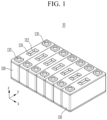
- FIG. 1 is a perspective view of a battery pack according to an embodiment.
- the battery pack 10 may include a plurality of cells 100 inserted in an inner space of a pack case.
- a plurality of cells 100 may be connected in series or parallel to each other.
- the cell 100 may accommodate an electrode assembly and an electrolyte inside a cell case constituting a body, and may form a vent hole 110 and electrode terminals 120 and 130 on an outer surface of the cell case.
- the vent hole 110 may be generally kept closed. If an event such as thermal runaway of the cell 100 occurs and gas or flame is generated inside the cell 100, the vent hole may be opened to output gas or flame to the outside of the cell 100.
- the vent hole 110 may be provided in such a way that a notch 112 is formed at a specific portion so that the specific portion is broken if the internal pressure of the cell 100 increases.
- the cell 100 may be configured as a prismatic cell.
- the vent hole 110 may be configured at the top of the cell 100 in an upright state.
- the cell 100 may be configured as a cell of another shape (e.g., a cylindrical cell), and the shape of the cell 100 is not limited thereto.
- the cells 100 inserted in one pack case may be arranged so that the vent holes 110 of the cells 100 are arranged side by side while facing the same direction (Z-axis direction).
- cell monitoring apparatus for a battery, wherein the battery includes a plurality of cells. Each cell includes a vent hole.
- the cell monitoring apparatus being configured to detect whether the vent hole of each cell is open using a plurality of missing holes formed corresponding to the location of the vent hole of each cell, and to detect a cell in which an event has occurred based on whether each cell is open.
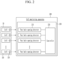
- FIG. 2 is a diagram illustrating a cell monitoring apparatus according to an embodiment
- FIG. 3 is a diagram illustrating the vent hole opening detector shown in FIG. 2 .
- the cell monitoring apparatus 200 may include a plurality of vent hole opening detectors 210 and a controller 220.
- the plurality of vent hole opening detectors 210 and the controller 220 may be mounted on a printed circuit board (PCB) 230.
- PCB printed circuit board
- the plurality of vent hole opening detectors 210 respectively correspond to the plurality of cells 100 constituting the battery pack 10, and may detect whether the vent holes 110 formed in the corresponding cells 100 are open.
- the cell monitoring apparatus may include missing holes.
- a missing hole may be a non-through hole.
- the purpose of the non-through holes is that, if they are placed in the PCB, in the event of thermal runaway, the entire PCB will not be destroyed, only the part of the non-through holes may be destroyed.
- a non-through hole may also be referred to as a blind hole.
- a missing hole may be a perforated area.
- each of the plurality of vent hole opening detectors 210 may include a missing hole group 212 and resistors R1 and R2. In FIG. 3 , only one vent hole opening detector 210 is shown for convenience.
- the missing hole group 212 may be disposed in an area 214 corresponding to a vent hole formed in a corresponding cell.
- the missing hole group 212 may include a plurality of missing holes 2121 spaced apart from each other at predetermined intervals along the circumference of the vent hole 110 formed in the corresponding cell 100 on the PCB 230.
- the resistors R1 and R2 may constitute a resistive voltage divider circuit. One end of the resistor R1 may be connected to a power terminal supplying the power voltage VCC, the other end of the resistor R2 may be connected to one end of the resistor R2, and the other end of the resistor R2 may be connected to ground. In this case, the resistor R2 may be disposed in an area 214 where the missing hole group 212 is located. A node N1 corresponding to a contact point between the resistors R1 and R2 may be connected to the controller 220. The power supply voltage VCC is divided by the resistors R1 and R2, and the voltage of the node N1 divided by the resistors R1 and R2 may be transmitted to the controller 220.
- the controller 220 may detect a cell in which an event such as thermal runaway has occurred from the voltages of the node N1 transmitted from the plurality of vent hole opening detector 210.
- the controller 220 may include a plurality of input terminals, and the voltages of the node N1 transmitted from the plurality of vent hole opening detectors 210 may be input through different input terminals of the controller 220. Accordingly, the controller 220 may detect a cell in which an event has occurred from the voltages of the node N1 transmitted from the plurality of vent hole opening detectors 210. Alternatively, the voltages of the node N1 transmitted from several event hole opening detectors 210 may be input to one input terminal of the controller 220. In this case, the voltages of the node N1 transmitted from the event hole opening detectors 210 detecting whether the vent holes 110 of adjacent cells 100 are open may be input to one input terminal of the controller 220.
- the controller 220 may be an analog front end (AFE) integrated circuit (IC).
- the controller 220 may be a microcontroller or a radio frequency (RF) IC.
- the vent hole 110 of the cell 100 is opened by the pressure of the gas generated inside the cell 100. Accordingly, a space between the missing holes 2121 formed corresponding to the corresponding cell 100 may be opened, and an area 214 where the missing hole group 212 is located may be damaged. Then, the resistor R2 disposed in the area 214 where the missing hole group 212 is located is opened. The opening of the resistor R2 may mean that the circuit is disconnected.
- the voltage at the node N1 may vary depending on whether the resistor R2 is open or shorted. Accordingly, the controller 220 may detect a cell in which an event such as thermal runaway has occurred based on the voltage of the node N1.
- the voltage at the node N1 becomes 2.5 V due to the resistive voltage division, and the voltage of 2.5 V may be transmitted to the controller 220.
- the resistor R2 disposed in the area 214 where the missing hole group 212 was located is open.
- the voltage of the node N1 becomes 5 V by the resistive voltage division, and the voltage of 5 V can be transmitted to the controller 220.
- the controller 220 may check the voltage of 5 V and detect a cell in which an event such as thermal runaway has occurred.
- the controller 220 may stop charging or discharging of the battery pack 10.
- the cell monitoring apparatus 200 may be implemented as a battery management system (BMS) that monitors the state of the battery pack 10.
- BMS battery management system
- the cell monitoring apparatus 200 may include at least one processor. At least one processor may be implemented in various types such as an application processor (AP), a central processing unit (CPU), a graphics processing unit (GPU), and the like.
- the at least one processor may store program commands for implementing at least some functions of the plurality of vent hole open detectors 210 and the controller 220 in a memory and execute the program commands stored in the memory to perform a cell monitoring operation.
- AP application processor
- CPU central processing unit
- GPU graphics processing unit
- the at least one processor may store program commands for implementing at least some functions of the plurality of vent hole open detectors 210 and the controller 220 in a memory and execute the program commands stored in the memory to perform a cell monitoring operation.
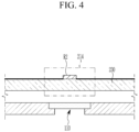
- FIG. 4 is a diagram showing a position of a resistor shown in FIG. 3 .
- the resistor R2 may be disposed in the area 214 where the missing hole group 212 is located.
- the missing hole group 212 may be positioned to correspond to the vent hole 110 formed in the corresponding cell 100.
- the resistor R2 Since the resistor R2 is disposed in the area 214 where the missing hole group 212 is located, if thermal runaway occurs in any one cell, the resistor R2 disposed in the area 214 where the missing hole group 212 corresponding to the cell where the thermal runaway has occurred is located may be open.
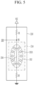
- FIG. 5 is a view showing an example of a position of a resistor in the vent hole opening detector shown in FIG. 2 .
- resistor R2 may be located outside the area 214 where the missing hole group 212 is located.
- the node N1 and the resistor R2 may be connected by a metal wiring pattern 216, and the metal wiring pattern 216 may be formed to pass through the area 214 where the missing hole group 212 is located.
- the resistor R2 may be opened.
- the cell monitoring apparatus 200 has a plurality of missing holes 2121 and a resistor R2 and/or a metal wiring pattern 216 for connection with the resistor R2 in the region 214 corresponding to the vent hole 110, it is possible to accurately identify a cell in which an event such as thermal runaway has occurred.
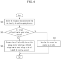
- FIG. 6 is a flowchart illustrating a cell monitoring method of a cell monitoring apparatus according to an embodiment.
- the controller 220 of the cell monitoring apparatus 200 may receive the voltages of the node N1 detected from the plurality of vent hole opening detectors 210 (S610).
- the controller 220 of the cell monitoring apparatus 200 may check whether a voltage different from a normal voltage is detected among the voltages of the node N1 detected by the plurality of vent hole opening detector 210.
- the normal voltage may refer to the voltage detected in the normal state of the cell as the voltage of the node N1, and the normal voltage may refer to 2.5 V in the case of the above-described example.
- the voltage different from a normal voltage is the voltage of the node N1 detected if an event such as thermal runaway occurs, and may refer to 5 V in the case of the example described above.
- the controller 220 of the cell monitoring apparatus 200 may determine the cell indicated by the vent hole opening detector 210 outputting a different voltage from the normal voltage as the cell in which the event has occurred (S630).
- the controller 220 of the cell monitoring apparatus 200 may determine that no event has occurred in all cells (S640).
- a bad sensor and an actual thermal runaway situation can be distinguished, an accurate situation can be notified to passengers, and a diagnosis mode can be accurately implemented.
Landscapes
- Chemical & Material Sciences (AREA)
- Chemical Kinetics & Catalysis (AREA)
- Electrochemistry (AREA)
- General Chemical & Material Sciences (AREA)
- Engineering & Computer Science (AREA)
- Manufacturing & Machinery (AREA)
- Microelectronics & Electronic Packaging (AREA)
- Business, Economics & Management (AREA)
- Emergency Management (AREA)
- Physics & Mathematics (AREA)
- General Physics & Mathematics (AREA)
- Secondary Cells (AREA)
- Battery Mounting, Suspending (AREA)
Abstract
The cell monitoring apparatus includes a plurality of vent hole opening detectors and a controller. The plurality of vent hole opening detectors are located in correspondence with each of a plurality of cells, includes a plurality of missing holes formed corresponding to the position of the vent hole of the corresponding cell, and detects whether or not the vent hole formed in each of the plurality of cells is open using the plurality of missing holes. The controller detects a cell in which an event has occurred based on whether a vent hole formed in each of the plurality of cells is open.
Description
- The present disclosure relates to a cell monitoring apparatus and a battery pack including the apparatus.
- In general, for diagnosing thermal runaway of a battery system, a method of monitoring temperature in a battery module and voltages of battery cells or a method using a pressure sensor is mainly used.
- However, the thermal runaway diagnosis method makes it difficult to clearly identify which battery cell started thermal runaway or how thermal propagation progressed.
- At least one of the embodiments is to provide a cell monitoring apparatus capable of detecting a battery cell in which thermal runaway has occurred and a battery pack including the apparatus.
- According to one aspect, a cell monitoring apparatus is provided. The cell monitoring apparatus includes: a plurality of vent hole opening detectors that are located in correspondence with each of a plurality of cells, includes a plurality of missing holes formed corresponding to the position of the vent hole of the corresponding cell, and detects whether or not the vent hole formed in each of the plurality of cells is open using the plurality of missing holes; and a controller that detects a cell in which an event has occurred based on whether a vent hole formed in each of the plurality of cells is open.
- Each of the plurality of vent hole opening detectors may include a first resistor and a second resistor connected in series between a power terminal supplying a power voltage and the ground, and having a contact point connected to the controller, and the first resistor or the second resistor may be located in an area where the plurality of missing holes are located, or a first metal wiring pattern for connection with the first resistor or a second metal wiring pattern for connection with the second resistor may be located in an area where the plurality of missing holes are located.
- The controller may determine the opening of the vent hole from the voltage of the contact point, and determine a cell in which the event has occurred from the opening of the vent hole.
- The plurality of missing holes may be formed at set intervals along the circumference of the vent hole.
- The event may include thermal runaway.
- According to another aspect, a battery pack is provided. The battery pack includes: a plurality of cells each formed with a plurality of vent holes; and a cell monitoring apparatus that detects whether the vent hole of each cell is open using a plurality of missing holes formed corresponding to the location of the vent hole of each cell, and detects a cell in which an event has occurred based on whether each cell is open.
- The plurality of missing holes may be formed at set intervals along the circumference of the vent hole.
- The cell monitoring apparatus may include a plurality of vent hole opening detectors for detecting whether a vent hole formed in each of the plurality of cells is open using the plurality of missing holes, each of the plurality of vent hole opening detectors may include a first resistor and a second resistor connected in series between a power terminal supplying a power voltage and a ground, and the first resistor or the second resistor may be located in an area where the plurality of missing holes are located, or a first metal wiring pattern for connection with the first resistor or a second metal wiring pattern for connection with the second resistor may be located in an area where the plurality of missing holes are located.
- The cell monitoring apparatus further may further include a controller for determining whether the vent hole is open based on the voltage of the contact point.
- A resistor located in an area where the plurality of missing holes are located or a resistor connected to a metal wiring pattern located in an area where the plurality of missing holes are located may be opened if an event of a corresponding cell occurs.
- At least some of the above features that accord with the invention and other features according to the invention are set out in the claims.
-
-
FIG. 1 is a perspective view of a battery pack according to an embodiment. -
FIG. 2 is a diagram illustrating a cell monitoring apparatus according to an embodiment. -
FIG. 3 is a diagram illustrating the vent hole opening detector shown inFIG. 2 . -
FIG. 4 is a diagram showing a position of a resistor shown inFIG. 3 . -
FIG. 5 is a view showing an example of a position of a resistor in the vent hole opening detector shown inFIG. 2 . -
FIG. 6 is a flowchart illustrating a cell monitoring method of a cell monitoring apparatus according to an embodiment. - Hereinafter, embodiments of the disclosure will be described in detail with reference to the attached drawings so that a person of ordinary skill in the art may easily implement the disclosure. As those skilled in the art would realize, the described embodiments may be modified in various different ways, all without departing from the scope of the claims. The drawings and description are to be regarded as illustrative in nature and not restrictive. Like reference numerals designate like elements throughout the specification. In the flowchart described with reference to the drawings in this specification, the order of operations may be changed, several operations may be merged, some operations may be divided, and specific operations may not be performed.
- Throughout the specification and claims, when a part is referred to "include" a certain element, it means that it may further include other elements rather than exclude other elements, unless specifically indicated otherwise.
- In addition, expressions described in the singular may be interpreted in the singular or plural unless explicit expressions such as "one" or "single" are used.
- In addition, terms including an ordinal number, such as first, second, etc., may be used to describe various elements, but the elements are not limited by the terms. The above terms are used only for the purpose of distinguishing one element from another element. For example, without departing from the scope of the present disclosure, a first element may be referred to as a second element, and similarly, a second element may be referred to as a first element.
- Furthermore, when a component is referred to be "connected" with another component, it includes not only the case where two components are "directly connected" but also the case where two components are "indirectly or non-contactedly connected" with another component interposed therebetween, or the case where two components are "electrically connected." On the other hand, when an element is referred to as "directly connected" to another element, it should be understood that no other element exists in the middle.
-
FIG. 1 is a perspective view of a battery pack according to an embodiment. - Referring to
FIG. 1 , thebattery pack 10 may include a plurality ofcells 100 inserted in an inner space of a pack case. - A plurality of
cells 100 may be connected in series or parallel to each other. - The
cell 100 may accommodate an electrode assembly and an electrolyte inside a cell case constituting a body, and may form avent hole 110 andelectrode terminals - The
vent hole 110 may be generally kept closed. If an event such as thermal runaway of thecell 100 occurs and gas or flame is generated inside thecell 100, the vent hole may be opened to output gas or flame to the outside of thecell 100. For example, thevent hole 110 may be provided in such a way that anotch 112 is formed at a specific portion so that the specific portion is broken if the internal pressure of thecell 100 increases. - The
cell 100 may be configured as a prismatic cell. In this case, thevent hole 110 may be configured at the top of thecell 100 in an upright state. Alternatively, thecell 100 may be configured as a cell of another shape (e.g., a cylindrical cell), and the shape of thecell 100 is not limited thereto. - The
cells 100 inserted in one pack case may be arranged so that thevent holes 110 of thecells 100 are arranged side by side while facing the same direction (Z-axis direction). - In embodiments, there is provided cell monitoring apparatus for a battery, wherein the battery includes a plurality of cells. Each cell includes a vent hole. The cell monitoring apparatus being configured to detect whether the vent hole of each cell is open using a plurality of missing holes formed corresponding to the location of the vent hole of each cell, and to detect a cell in which an event has occurred based on whether each cell is open.
-
FIG. 2 is a diagram illustrating a cell monitoring apparatus according to an embodiment, andFIG. 3 is a diagram illustrating the vent hole opening detector shown inFIG. 2 . - Referring to
FIG. 2 , thecell monitoring apparatus 200 may include a plurality of venthole opening detectors 210 and acontroller 220. The plurality of venthole opening detectors 210 and thecontroller 220 may be mounted on a printed circuit board (PCB) 230. - The plurality of vent
hole opening detectors 210 respectively correspond to the plurality ofcells 100 constituting thebattery pack 10, and may detect whether thevent holes 110 formed in thecorresponding cells 100 are open. - In embodiments, the cell monitoring apparatus may include missing holes. In embodiments, a missing hole may be a non-through hole. The purpose of the non-through holes is that, if they are placed in the PCB, in the event of thermal runaway, the entire PCB will not be destroyed, only the part of the non-through holes may be destroyed. A non-through hole may also be referred to as a blind hole. In embodiments, a missing hole may be a perforated area.
- Referring to
FIG. 3 , each of the plurality of venthole opening detectors 210 may include amissing hole group 212 and resistors R1 and R2. InFIG. 3 , only one venthole opening detector 210 is shown for convenience. - The missing
hole group 212 may be disposed in anarea 214 corresponding to a vent hole formed in a corresponding cell. - The missing
hole group 212 may include a plurality of missingholes 2121 spaced apart from each other at predetermined intervals along the circumference of thevent hole 110 formed in thecorresponding cell 100 on thePCB 230. - The resistors R1 and R2 may constitute a resistive voltage divider circuit. One end of the resistor R1 may be connected to a power terminal supplying the power voltage VCC, the other end of the resistor R2 may be connected to one end of the resistor R2, and the other end of the resistor R2 may be connected to ground. In this case, the resistor R2 may be disposed in an
area 214 where the missinghole group 212 is located. A node N1 corresponding to a contact point between the resistors R1 and R2 may be connected to thecontroller 220. The power supply voltage VCC is divided by the resistors R1 and R2, and the voltage of the node N1 divided by the resistors R1 and R2 may be transmitted to thecontroller 220. - Again referring to
FIG. 2 , thecontroller 220 may detect a cell in which an event such as thermal runaway has occurred from the voltages of the node N1 transmitted from the plurality of venthole opening detector 210. - The
controller 220 may include a plurality of input terminals, and the voltages of the node N1 transmitted from the plurality of venthole opening detectors 210 may be input through different input terminals of thecontroller 220. Accordingly, thecontroller 220 may detect a cell in which an event has occurred from the voltages of the node N1 transmitted from the plurality of venthole opening detectors 210. Alternatively, the voltages of the node N1 transmitted from several eventhole opening detectors 210 may be input to one input terminal of thecontroller 220. In this case, the voltages of the node N1 transmitted from the eventhole opening detectors 210 detecting whether the vent holes 110 ofadjacent cells 100 are open may be input to one input terminal of thecontroller 220. - The
controller 220 may be an analog front end (AFE) integrated circuit (IC). Thecontroller 220 may be a microcontroller or a radio frequency (RF) IC. - If an event such as thermal runaway occurs, the
vent hole 110 of thecell 100 is opened by the pressure of the gas generated inside thecell 100. Accordingly, a space between the missingholes 2121 formed corresponding to thecorresponding cell 100 may be opened, and anarea 214 where the missinghole group 212 is located may be damaged. Then, the resistor R2 disposed in thearea 214 where the missinghole group 212 is located is opened. The opening of the resistor R2 may mean that the circuit is disconnected. - The voltage at the node N1 may vary depending on whether the resistor R2 is open or shorted. Accordingly, the
controller 220 may detect a cell in which an event such as thermal runaway has occurred based on the voltage of the node N1. - For example, if the resistance values of the resistors R1 and R2 are 10K and the power supply voltage is 5 V, the voltage at the node N1 becomes 2.5 V due to the resistive voltage division, and the voltage of 2.5 V may be transmitted to the
controller 220. At this time, a thermal runaway occurred in one of the cells, and themissing hole group 212 formed corresponding to the cell in which the thermal runaway occurred was destroyed, the resistor R2 disposed in thearea 214 where the missinghole group 212 was located is open. Then, the voltage of the node N1 becomes 5 V by the resistive voltage division, and the voltage of 5 V can be transmitted to thecontroller 220. Thecontroller 220 may check the voltage of 5 V and detect a cell in which an event such as thermal runaway has occurred. - If a cell in which an event has occurred is detected, the
controller 220 may stop charging or discharging of thebattery pack 10. - The
cell monitoring apparatus 200 may be implemented as a battery management system (BMS) that monitors the state of thebattery pack 10. - The
cell monitoring apparatus 200 may include at least one processor. At least one processor may be implemented in various types such as an application processor (AP), a central processing unit (CPU), a graphics processing unit (GPU), and the like. The at least one processor may store program commands for implementing at least some functions of the plurality of vent holeopen detectors 210 and thecontroller 220 in a memory and execute the program commands stored in the memory to perform a cell monitoring operation. -
FIG. 4 is a diagram showing a position of a resistor shown inFIG. 3 . - Referring to
FIG. 4 , the resistor R2 may be disposed in thearea 214 where the missinghole group 212 is located. - As described above, the missing
hole group 212 may be positioned to correspond to thevent hole 110 formed in thecorresponding cell 100. - Since the resistor R2 is disposed in the
area 214 where the missinghole group 212 is located, if thermal runaway occurs in any one cell, the resistor R2 disposed in thearea 214 where the missinghole group 212 corresponding to the cell where the thermal runaway has occurred is located may be open. -
FIG. 5 is a view showing an example of a position of a resistor in the vent hole opening detector shown inFIG. 2 . - Referring to
FIG. 5 , resistor R2 may be located outside thearea 214 where the missinghole group 212 is located. The node N1 and the resistor R2 may be connected by ametal wiring pattern 216, and themetal wiring pattern 216 may be formed to pass through thearea 214 where the missinghole group 212 is located. - In this way, if thermal runaway occurs in one cell, in the
area 214 where the missinghole group 212 corresponding to the cell where the thermal runaway has occurred is located may be damaged and themetal wiring pattern 216 may be cut off. Accordingly, the resistor R2 may be opened. - As such, the
cell monitoring apparatus 200, as shown inFIGS. 3 to 5 , has a plurality of missingholes 2121 and a resistor R2 and/or ametal wiring pattern 216 for connection with the resistor R2 in theregion 214 corresponding to thevent hole 110, it is possible to accurately identify a cell in which an event such as thermal runaway has occurred. -
FIG. 6 is a flowchart illustrating a cell monitoring method of a cell monitoring apparatus according to an embodiment. - Referring to
FIG. 6 , thecontroller 220 of thecell monitoring apparatus 200 may receive the voltages of the node N1 detected from the plurality of vent hole opening detectors 210 (S610). - The
controller 220 of thecell monitoring apparatus 200 may check whether a voltage different from a normal voltage is detected among the voltages of the node N1 detected by the plurality of venthole opening detector 210. The normal voltage may refer to the voltage detected in the normal state of the cell as the voltage of the node N1, and the normal voltage may refer to 2.5 V in the case of the above-described example. The voltage different from a normal voltage is the voltage of the node N1 detected if an event such as thermal runaway occurs, and may refer to 5 V in the case of the example described above. - If a voltage different from the normal voltage is detected (S620), the
controller 220 of thecell monitoring apparatus 200 may determine the cell indicated by the venthole opening detector 210 outputting a different voltage from the normal voltage as the cell in which the event has occurred (S630). - Meanwhile, if a voltage different from the normal voltage is not detected (S620), the
controller 220 of thecell monitoring apparatus 200 may determine that no event has occurred in all cells (S640). - According to at least one embodiment, it is possible to detect a cell in which thermal runaway has occurred, and based on this, a bad sensor and an actual thermal runaway situation can be distinguished, an accurate situation can be notified to passengers, and a diagnosis mode can be accurately implemented.
- Although the embodiments have been described in detail above, the scope of the present disclosure is not limited thereto, and various modifications and improvements made by those skilled in the art using the basic concept of the present disclosure defined in the following claims are also included in the scope of the present disclosure.
-
- 10: battery pack
- 100: cell
- 100: cell
- 110: vent hole
- 112: notch
- 120, 130: electrode terminal
- 200: cell monitoring apparatus
- 210: vent hole open detector
- 220: controller
- 230: PCB
- 212: missing hole group
- 2121: missing hole
- Further understanding of the invention may be obtained from the embodiments described in the following numbered clauses:
- 1. A cell monitoring apparatus comprising:
- a plurality of vent hole opening detectors that are located in correspondence with each of a plurality of cells, comprises a plurality of missing holes formed corresponding to the position of the vent hole of the corresponding cell, and detects whether or not the vent hole formed in each of the plurality of cells is open using the plurality of missing holes; and
- a controller that detects a cell in which an event has occurred based on whether a vent hole formed in each of the plurality of cells is open.
- 2. The cell monitoring apparatus of clause 1, wherein
- each of the plurality of vent hole opening detectors comprises a first resistor and a second resistor that are connected in series between a power terminal supplying a power voltage and the ground, and having a contact point connected to the controller, and
- the first resistor or the second resistor is located in an area where the plurality of missing holes are located, or a first metal wiring pattern for connection with the first resistor or a second metal wiring pattern for connection with the second resistor is located in an area where the plurality of missing holes are located.
- 3. The cell monitoring apparatus of clause 2, wherein
the controller determines the opening of the vent hole from the voltage of the contact point, and determines a cell in which the event has occurred from the opening of the vent hole. - 4. The cell monitoring apparatus of clause 1, wherein
the plurality of missing holes are formed at set intervals along the circumference of the vent hole. - 5. The cell monitoring apparatus of clause 1, wherein
the event comprises thermal runaway. - 6. A battery pack comprising:
- a plurality of cells each formed with a plurality of vent holes; and
- a cell monitoring apparatus that detects whether the vent hole of each cell is open using a plurality of missing holes formed corresponding to the location of the vent hole of each cell, and detects a cell in which an event has occurred based on whether each cell is open.
- 7. The battery pack of clause 6, wherein
the plurality of missing holes are formed at set intervals along the circumference of the vent hole. - 8. The battery pack of clause 6, wherein
- the cell monitoring apparatus comprises a plurality of vent hole opening detectors for detecting whether a vent hole formed in each of the plurality of cells is open using the plurality of missing holes,
- each of the plurality of vent hole opening detectors comprises a first resistor and a second resistor connected in series between a power terminal supplying a power voltage and a ground, and
- the first resistor or the second resistor is located in an area where the plurality of missing holes are located, or a first metal wiring pattern for connection with the first resistor or a second metal wiring pattern for connection with the second resistor is located in an area where the plurality of missing holes are located.
- 9. The battery pack of clause 8, wherein
the cell monitoring apparatus further comprises a controller for determining whether the vent hole is open based on the voltage of the contact point. - 10. The battery pack of clause 8, wherein
a resistor located in an area where the plurality of missing holes are located or a resistor connected to a metal wiring pattern located in an area where the plurality of missing holes are located is opened if an event of a corresponding cell occurs.
Claims (8)
- A cell monitoring apparatus for a battery, wherein the battery comprises a plurality of cells, each cell comprising a vent hole, the cell monitoring apparatus being configured to:detect whether the vent hole of each cell is open using a plurality of missing holes formed corresponding to the location of the vent hole of each cell; anddetect a cell in which an event has occurred based on whether each cell is open.
- A cell monitoring apparatus as claimed in claim 1, comprising:a plurality of vent hole opening detectors that are located in correspondence with each of a plurality of cells, wherein each vent opening hole detector comprises a plurality of missing holes formed corresponding to the position of the vent hole of the corresponding cell, and is configured to detect whether or not the vent hole formed in each of the plurality of cells is open using the plurality of missing holes; anda controller configured to detect a cell in which an event has occurred based on whether a vent hole formed in each of the plurality of cells is open.
- The cell monitoring apparatus as claimed in claim 2, whereineach of the plurality of vent hole opening detectors comprises a first resistor and a second resistor that are connected in series between a power terminal supplying a power voltage and the ground, and has a contact point connected to the controller, andthe first resistor or the second resistor is located in an area where the plurality of missing holes are located, or a first metal wiring pattern for connection with the first resistor or a second metal wiring pattern for connection with the second resistor is located in an area where the plurality of missing holes are located.
- The cell monitoring apparatus as claimed in claim 3, wherein
a resistor located in an area where the plurality of missing holes are located or a resistor connected to a metal wiring pattern located in an area where the plurality of missing holes are located is configured to be opened if an event of a corresponding cell occurs. - The cell monitoring apparatus as claimed in claim 3 or claim 4, wherein
the controller is configured to determine the opening of the vent hole from the voltage of the contact point, and to determine a cell in which the event has occurred from the opening of the vent hole. - The cell monitoring apparatus as claimed in any preceding claim, wherein
the plurality of missing holes are formed at set intervals along the circumference of the vent hole. - The cell monitoring apparatus as claimed in any preceding claim, wherein
the event comprises thermal runaway. - A battery pack comprising:a plurality of cells each formed with a plurality of vent holes; anda cell monitoring apparatus according to any preceding claim.
Applications Claiming Priority (1)
| Application Number | Priority Date | Filing Date | Title |
|---|---|---|---|
| KR1020230035397A KR20240140691A (en) | 2023-03-17 | 2023-03-17 | Cell monitoring appatatus and battery pack including the apparatus |
Publications (1)
| Publication Number | Publication Date |
|---|---|
| EP4432420A1 true EP4432420A1 (en) | 2024-09-18 |
Family
ID=87003052
Family Applications (1)
| Application Number | Title | Priority Date | Filing Date |
|---|---|---|---|
| EP23181584.6A Pending EP4432420A1 (en) | 2023-03-17 | 2023-06-26 | Cell monitoring apparatus and battery pack including the apparatus |
Country Status (3)
| Country | Link |
|---|---|
| US (1) | US20240313279A1 (en) |
| EP (1) | EP4432420A1 (en) |
| KR (1) | KR20240140691A (en) |
Citations (3)
| Publication number | Priority date | Publication date | Assignee | Title |
|---|---|---|---|---|
| US20160111757A1 (en) * | 2014-10-20 | 2016-04-21 | Samsung Sdi Co., Ltd. | Battery module with fusible conductors |
| KR20190032883A (en) * | 2017-09-20 | 2019-03-28 | 삼성에스디아이 주식회사 | Battery management sytem |
| US20220077507A1 (en) * | 2020-07-30 | 2022-03-10 | Cummins Inc. | Detecting thermal events in battery packs |
-
2023
- 2023-03-17 KR KR1020230035397A patent/KR20240140691A/en active Pending
- 2023-05-22 US US18/321,671 patent/US20240313279A1/en active Pending
- 2023-06-26 EP EP23181584.6A patent/EP4432420A1/en active Pending
Patent Citations (3)
| Publication number | Priority date | Publication date | Assignee | Title |
|---|---|---|---|---|
| US20160111757A1 (en) * | 2014-10-20 | 2016-04-21 | Samsung Sdi Co., Ltd. | Battery module with fusible conductors |
| KR20190032883A (en) * | 2017-09-20 | 2019-03-28 | 삼성에스디아이 주식회사 | Battery management sytem |
| US20220077507A1 (en) * | 2020-07-30 | 2022-03-10 | Cummins Inc. | Detecting thermal events in battery packs |
Also Published As
| Publication number | Publication date |
|---|---|
| US20240313279A1 (en) | 2024-09-19 |
| KR20240140691A (en) | 2024-09-24 |
Similar Documents
| Publication | Publication Date | Title |
|---|---|---|
| US11802918B2 (en) | Thermal runaway detecting device, battery system, and thermal runaway detecting method of battery system | |
| US12411179B2 (en) | Battery diagnosing apparatus and method | |
| US8587318B2 (en) | Sensor arrangement for an energy storage device and a method of using the same | |
| EP2291670B1 (en) | Cell diagnostic system and method | |
| US11513139B2 (en) | Battery pack diagnosis apparatus | |
| US9716520B2 (en) | Integrated standard-compliant data acquisition device | |
| US20210288356A1 (en) | Abnormality detection device and abnormality detection method for battery pack | |
| KR102949544B1 (en) | Battery Pack with improved accuracy of swelling measurement | |
| KR102883880B1 (en) | Apparatus and method for diagnosing battery | |
| JP2010271267A (en) | Battery monitoring device | |
| KR102436468B1 (en) | Battery Powered Equipment Diagnostic Human-Machine Interface System | |
| US11130406B2 (en) | Integrated standard-compliant data acquisition device | |
| EP4432420A1 (en) | Cell monitoring apparatus and battery pack including the apparatus | |
| US7982593B2 (en) | Alarm device of vehicle battery for monitoring voltage ranges in charging and discharging processes of vehicle battery | |
| KR20220014716A (en) | System and method for verifying thermal propagation design of battery pack | |
| EP4507086A1 (en) | Battery system with impact detection | |
| EP4455699B1 (en) | Battery monitoring device and battery management system | |
| US20230358824A1 (en) | Interlock diagnosing system and method for a high voltage device | |
| ES3062605T3 (en) | Relay state management device and operation method therefor | |
| EP4068467B1 (en) | Battery cell and battery system comprising the same | |
| KR20240039256A (en) | System and method for monitoring battery in activation process | |
| US20240128524A1 (en) | Battery System and Battery Cell Assembly | |
| EP4525133A1 (en) | Battery system and flexible printed circuit board | |
| EP4700407A1 (en) | Battery management system, battery device, and method for diagnosing cell voltage measurement line | |
| KR20240101377A (en) | Battery system and flexible printed circuit board |
Legal Events
| Date | Code | Title | Description |
|---|---|---|---|
| PUAI | Public reference made under article 153(3) epc to a published international application that has entered the european phase |
Free format text: ORIGINAL CODE: 0009012 |
|
| STAA | Information on the status of an ep patent application or granted ep patent |
Free format text: STATUS: REQUEST FOR EXAMINATION WAS MADE |
|
| 17P | Request for examination filed |
Effective date: 20230626 |
|
| AK | Designated contracting states |
Kind code of ref document: A1 Designated state(s): AL AT BE BG CH CY CZ DE DK EE ES FI FR GB GR HR HU IE IS IT LI LT LU LV MC ME MK MT NL NO PL PT RO RS SE SI SK SM TR |