EP4432323A1 - Disconnector and earthing switch with telescopic contact - Google Patents
Disconnector and earthing switch with telescopic contact Download PDFInfo
- Publication number
- EP4432323A1 EP4432323A1 EP24162507.8A EP24162507A EP4432323A1 EP 4432323 A1 EP4432323 A1 EP 4432323A1 EP 24162507 A EP24162507 A EP 24162507A EP 4432323 A1 EP4432323 A1 EP 4432323A1
- Authority
- EP
- European Patent Office
- Prior art keywords
- disconnector
- blade
- contact
- earthing switch
- earthing
- Prior art date
- Legal status (The legal status is an assumption and is not a legal conclusion. Google has not performed a legal analysis and makes no representation as to the accuracy of the status listed.)
- Granted
Links
Images


Classifications
-
- H—ELECTRICITY
- H01—ELECTRIC ELEMENTS
- H01H—ELECTRIC SWITCHES; RELAYS; SELECTORS; EMERGENCY PROTECTIVE DEVICES
- H01H31/00—Air-break switches for high tension without arc-extinguishing or arc-preventing means
- H01H31/003—Earthing switches
-
- H—ELECTRICITY
- H02—GENERATION; CONVERSION OR DISTRIBUTION OF ELECTRIC POWER
- H02B—BOARDS, SUBSTATIONS OR SWITCHING ARRANGEMENTS FOR THE SUPPLY OR DISTRIBUTION OF ELECTRIC POWER
- H02B13/00—Arrangement of switchgear in which switches are enclosed in, or structurally associated with, a casing, e.g. cubicle
- H02B13/02—Arrangement of switchgear in which switches are enclosed in, or structurally associated with, a casing, e.g. cubicle with metal casing
- H02B13/035—Gas-insulated switchgear
- H02B13/0354—Gas-insulated switchgear comprising a vacuum switch
-
- H—ELECTRICITY
- H02—GENERATION; CONVERSION OR DISTRIBUTION OF ELECTRIC POWER
- H02B—BOARDS, SUBSTATIONS OR SWITCHING ARRANGEMENTS FOR THE SUPPLY OR DISTRIBUTION OF ELECTRIC POWER
- H02B13/00—Arrangement of switchgear in which switches are enclosed in, or structurally associated with, a casing, e.g. cubicle
- H02B13/02—Arrangement of switchgear in which switches are enclosed in, or structurally associated with, a casing, e.g. cubicle with metal casing
- H02B13/035—Gas-insulated switchgear
- H02B13/045—Details of casing, e.g. gas tightness
-
- H—ELECTRICITY
- H01—ELECTRIC ELEMENTS
- H01H—ELECTRIC SWITCHES; RELAYS; SELECTORS; EMERGENCY PROTECTIVE DEVICES
- H01H1/00—Contacts
- H01H1/12—Contacts characterised by the manner in which co-operating contacts engage
- H01H1/36—Contacts characterised by the manner in which co-operating contacts engage by sliding
- H01H1/44—Contacts characterised by the manner in which co-operating contacts engage by sliding with resilient mounting
-
- H—ELECTRICITY
- H01—ELECTRIC ELEMENTS
- H01H—ELECTRIC SWITCHES; RELAYS; SELECTORS; EMERGENCY PROTECTIVE DEVICES
- H01H1/00—Contacts
- H01H1/50—Means for increasing contact pressure, preventing vibration of contacts, holding contacts together after engagement, or biasing contacts to the open position
-
- H—ELECTRICITY
- H01—ELECTRIC ELEMENTS
- H01H—ELECTRIC SWITCHES; RELAYS; SELECTORS; EMERGENCY PROTECTIVE DEVICES
- H01H3/00—Mechanisms for operating contacts
- H01H3/32—Driving mechanisms, i.e. for transmitting driving force to the contacts
- H01H3/46—Driving mechanisms, i.e. for transmitting driving force to the contacts using rod or lever linkage, e.g. toggle
-
- H—ELECTRICITY
- H01—ELECTRIC ELEMENTS
- H01H—ELECTRIC SWITCHES; RELAYS; SELECTORS; EMERGENCY PROTECTIVE DEVICES
- H01H31/00—Air-break switches for high tension without arc-extinguishing or arc-preventing means
- H01H31/26—Air-break switches for high tension without arc-extinguishing or arc-preventing means with movable contact that remains electrically connected to one line in open position of switch
- H01H31/28—Air-break switches for high tension without arc-extinguishing or arc-preventing means with movable contact that remains electrically connected to one line in open position of switch with angularly-movable contact
- H01H31/283—Air-break switches for high tension without arc-extinguishing or arc-preventing means with movable contact that remains electrically connected to one line in open position of switch with angularly-movable contact wherein the contact or contacts are rectilinearly movable with respect to the carrying member
Definitions
- the present application relates to an earthing disconnection switch (also called herein a disconnector and earthing switch).
- an earthing disconnection switch having a telescopic or retractable contact.
- a three-position earthing disconnection switch (or three position disconnector and earthing switch, 3PS) can be provided within a compact footprint by way of said retractable contact.
- Switchgears and other switching devices are used to control and protect electrical equipment, such as equipment operated by utilities, commercial building owners, and operators of distributed renewable generation assets such as solar farms and wind turbines.
- Such switchgears include various medium voltage devices (e.g., devices rated for 12kV or 24kV) for a range of applications, such as a ring main unit (RMU).
- RMU ring main unit
- a device comprising: one or more switching mechanisms configured to disconnect a power supply from a load; and one or more disconnector and earthing switches, each disconnector and earthing switch associated with a respective switching mechanism.
- Each disconnector and earthing switch comprising a telescopic disconnector blade having a first end and a second end, wherein the disconnector blade is configured to pivot around the first end between three different positions.
- the three positions comprise: a first position in which the disconnector and earthing switch is closed and the power supply is connected to the load through the disconnector blade; a second, isolation, position in which the disconnector and earthing switch is open and the power supply is disconnected from the load; and a third position in which the power supply is disconnected from the load and a second end of the disconnector blade is electrically connected to an earthing contact.
- a disconnector and earthing switch also termed an earthing disconnection switch
- 3PS switch three position disconnector and earthing switch
- disconnector and earthing switch with a telescopic or retractable contact (or disconnector blade) can facilitate provision of a reliable device with a small footprint and improved dielectric performance, which device can more easily and safely tested in-situ (thereby e.g., improve the ease of maintenance).
- a 3PS can be provided within a small footprint, which can lead to smaller device architecture.
- the telescopic disconnector blade comprises an outer contact and an inner contact, a portion of the inner contact arranged to slide within the outer contact.
- the outer contact comprises the first end of the disconnector blade and the inner contact comprises the second end of the disconnector blade.
- the outer contact comprises a guide hole and the inner contact slides within the guide hole, the disconnector blade further comprising a compliant member disposed within the guide hole and configured to bias the inner contact out of the guide hole.
- the inner contact in response to an external force applied in a first direction and to the second end of the disconnector blade, the inner contact is configured to slide in the first direction within the guide hole of the outer contact and the compliant member is configured to bias the inner contact in a direction opposite the first direction.
- the compliant member is a compression spring. Any other suitable compliant member can be used.
- the compliant member can be compliant through form and/or material.
- the device further comprises a housing having first and second side walls, wherein the telescopic disconnector blade is configured to rotate around the pivot from the first position to the second position, wherein the rotation is towards the second side wall of the housing.
- a telescopic or retractable blade as described herein can help maintain adequate between the second side wall and the tip or second end of the disconnector blade; this can help to reduce field intensity at the end of the blade and thereby help reduce or avoid the risk of dielectric failure between the housing and the blade.
- the second side wall comprises an insulating support configured to contact, when the disconnector blade is in the second position, the second end of said disconnector blade.
- the presence of the insulating support can act as an obstruction to help breakdown electrical current paths, and thereby help avoid dielectric failure by improving dielectric performance.
- the insulating support comprises a guide portion configured to cause the disconnector blade to move from the extended state to the compressed state as the disconnector blade pivots from the first position to the second position.
- the guide portion is further configured to cause the disconnector blade to move from the compressed state to the extended state as the disconnector blade pivots from the second position to the third position.
- the electrical contact coupled to the insulating support, the electrical contact configured to contact the second end of the disconnector blade when the disconnector blade is in the second position.
- the electrical contact comprises a partially spherical end configured to contact the second end of the disconnector blade when the disconnector blade is in the second position. The use of a spherical end can help to reduce field end effects.
- each disconnector and earthing switch comprises two or more telescopic disconnector blades. By using two disconnector blades, two parallel paths are created for current flow. This can help to improve thermal performance.
- each disconnector and earthing switch comprises a single telescopic disconnector blade.
- the device comprises a vacuum circuit breaker.
- the one or more switching mechanisms comprise a vacuum interrupter.
- the device comprises a plurality of switching devices, each switching device comprising a plurality of poles, wherein each pole is associated with a respective switching mechanism of the one or more switching mechanisms and a respective disconnector and earthing switch of the one or more disconnector and earthing switches.
- a more compact device architecture may be facilitated by the use of the telescopic or retractable blade described herein.
- the telescopic disconnector blade comprises an outer contact and a plurality of contacts, a portion of a first inner contact arranged to slide within the outer contact and a portion of a second first inner arranged to slide within the first inner contact.
- the telescopic disconnector blade comprises an outer contact and an inner contact, a portion of the outer contact arranged to slide over the inner contact.
- the inner contact comprises the first end of the disconnector blade.
- the outer contact comprises the second end of the disconnector blade.
- the telescopic disconnector blade comprises an outer contact and a plurality of inner contacts, a portion of the outer contact arranged to slide over a first inner contact, and a portion of the first inner contact arranged to slide over a second inner contact.
- the outer contact comprises the second end of the disconnector blade.
- a method of operating an disconnector and earthing switch comprising a telescopic disconnector blade having a first end and a second end, wherein the disconnector blade is configured to pivot around the first end between three different positions.
- the method comprises pivoting the disconnector blade about the first end from a first position, in which the disconnector and earthing switch is closed and the power supply is connected to the load through the disconnector blade, to a second position, wherein the second position is an isolation position in which the disconnector and earthing switch is open and the power supply is disconnected from the load.
- the method further comprises pivoting the disconnector blade about the first end from the second position to a third position in which the power supply is disconnected from the load and a second end of the disconnector blade is electrically connected to an earthing contact.
- the disconnector and earthing switch is a 3PS switch (three position disconnector and earthing switch).
- the method can further comprise compressing the disconnector blade as it pivots from the first position to the second position.
- the method can further comprise extending the disconnector blade as the disconnector blade pivots from the second position to the third position.
- a device comprising: one or more switching mechanisms configured to disconnect a power supply from a load; and one or more disconnector and earthing switches, each disconnector and earthing switch associated with a respective switching mechanism.
- Each disconnector and earthing switch comprising a telescopic disconnector blade having a first end and a second end, wherein the disconnector blade is configured to pivot around the first end between two or more different positions.
- the two or more positions comprise: a first position in which the disconnector and earthing switch is closed and the power supply is connected to the load through the disconnector blade; and a second position in which the power supply is disconnected from the load and a second end of the disconnector blade is electrically connected to an earthing contact.
- This can be implemented as a two position earthing disconnection switch.
- each disconnector and earthing switch comprises two or more telescopic disconnector blades.
- the two or more positions further comprise a third, isolation, position in which the disconnector and earthing switch is open and the power supply is disconnected from the load.
- the disconnector and earthing switch also called an earthing disconnection switch
- the disconnector and earthing switch is a 3PS switch.
- a switching device configured to disconnect a power supply from a load
- the switching device comprising a telescopic disconnector blade having a first end and a second end, wherein the disconnector blade is configured to pivot around the first end between two or more different positions.
- the two or more positions comprise: a first position in which the power supply is connected to the load through the disconnector blade; and a second position in which the power supply is disconnected from the load. In the second position, a second end of the disconnector blade can optionally be electrically connected to an earthing contact.
- a device 100 comprising one or more switching mechanisms 110 configured to disconnect a power supply from a load and one or more corresponding disconnector and earthing switches 330 is described.
- Each disconnector and earthing switch is associated with a respective switching mechanism.
- the disconnector and earthing switch is a 3PS switch (three position disconnector and earthing switch), but it will be understood that the principles of the telescopic blade can be applied to other earthing disconnection switches (e.g. a two position earthing disconnection switch) and to other switch types more generally.
- Device 100 may be a switchgear or any other switching or disconnection device.
- the device can comprise a circuit breaker, optionally a vacuum circuit breaker VCB, or a load break switch, for example.
- device 100 may comprise a plurality of switching devices, each switching device comprising a plurality of poles.
- device 100 may be a three-way, three-Pole device.
- Each pole can be associated with a respective switching mechanism of the one or more switching mechanisms and associated with a respective disconnector and earthing switch of the one or more disconnector and earthing switches.
- Each of the plurality of switching devices may be optionally implemented as e.g. a vacuum circuit breaker VCB or a load break switch, for example.
- three switching mechanisms 110 are shown, but any suitable number of switching mechanisms (of any suitable type, e.g., mechanical, electromechanical and/or solid state) may be used.
- the switching mechanisms are provided within a housing 216.
- the housing has a first side wall 216a and a second side wall 216b and a bottom plate 216c.
- the switching mechanisms shown here are arranged along a first axis 102 between the first and second side walls 216a, 216b of housing 216.
- each disconnector and earthing switch has a disconnector blade 332 which is pivotably connected, at a first end 342, to the associated switching mechanism.
- the disconnector blade 332 is the disconnector and earthing switch contact, which facilitates electrical connection of the load to the power supply via the disconnector and earthing switch.
- the first end 342 of the disconnector blade (or contact) is pivotably connected or coupled to a top of a housing enclosing the switching mechanism.
- the disconnector blade 332 also comprises a second end 334 opposite the first end.
- each switching mechanism has a fixed contact and a moveable contact, and an actuating mechanism comprising a shaft 214 (extending into the page, here perpendicular to axis 102) and drive rod 344.
- the shaft is configured to rotate (here around a rotation axis arranged perpendicular to the first axis 102) to transfer an external input force to move the moveable contact and open or close the switching mechanism.
- the drive rod 344 is connected to the shaft 214 to transfer the rotation of the shaft 214 in response to an external input force into movement of the moveable contact along a second axis 106 perpendicular to the first axis.
- the second axis is also referred to herein as the operating axis.
- the moveable contact is moveable by the drive rod 344 of the actuating mechanism and is arranged between the fixed contact and the shaft 214 of the actuating mechanism.
- Each disconnector and earthing switch 330 is arranged between the active part of the switching mechanism 110 (here the moving and fixed contacts) and the shaft 214 along the second axis 106.
- the switching mechanism 110 is implemented as, or comprises, a vacuum interrupter (or VI).
- the VI can be implemented as part of a VCB or other circuit breaker, or as part of any other type of switching device (such as a load break switch or LBS).
- the top contact of the vacuum interrupter VI is the moveable contact, moveable by the actuating mechanism is response to rotation of the shaft 214.
- the fixed contact of the vacuum interrupter VI is fixed to the bottom plate 216c of the housing 216 via a support plate (not shown).
- the bottom plate 216c and first and second sidewalls 216a, 216b at least partially define a switching compartment of the switchgear 100, 200.
- the switching compartment described herein is air insulated, however any other insulating medium which fulfils the required dielectric / thermal requirements (such as a vacuum, pressurised air, SF6 (sulphur hexafluoride) or other gaseous dielectric medium, or inert gas) may be provided within the switching compartment.
- any other insulating medium which fulfils the required dielectric / thermal requirements such as a vacuum, pressurised air, SF6 (sulphur hexafluoride) or other gaseous dielectric medium, or inert gas
- a housing of the VI covers the fixed and moving contacts and is bolted to the support plate.
- Column supports formed of an insulating material (not shown) can be bolted between the support plate and the bottom plate 216c to hold the support plate within the switching compartment of the housing 216.
- the VI is mounted on a bushing 350.
- the bushing 350 is bolted to the bottom plate 216c and is fixed to the support plate with epoxy.
- the VI housing here acts as a support for the hinge or pivot point at the first end 342 of the disconnector blade 332.
- the first end of each disconnector blade is pivotably coupled to the switching mechanism 110.
- the first end of the disconnector blade 342 can be pivotably coupled to the switching mechanism between the moveable contact and the shaft 214.
- the first end of the disconnector blade 342 is pivotably coupled to a top of the VI housing which surrounds the fixed and moveable contacts of the switching mechanism 110.
- a metallic shield (not shown) can be provided within the VI housing, placed between the moveable contact and the first end of the disconnector blade.
- the metallic shield acts to help shield the disconnector blade and the hinge/pivotable coupling from any electric field within the vacuum interrupter.
- the moving contact moves within the VI housing in response to actuation/rotation of the shaft 214.
- rotation of the shaft 214 actuates the drive rod 344 of the actuating mechanism, pulling the moveable contact along the operating axis towards the shaft 214 and opening the switch 212.
- each disconnector and earthing switch 330 is arranged to pivot around the first end to move between three different positions, as is further illustrated in Figure 2 .
- the disconnector blade 332 is arranged in a first position in which in which the disconnector and earthing switch is closed and the power supply is connected to the load through the disconnector blade. In this first position, current flows through the device 100 via the switching mechanism 110 and the disconnector blade 332.
- the disconnector blade In response to user actuation of a direct break mechanism (not shown), the disconnector blade is moved from the first position to a second position, which is shown in Figure 2B .
- the direct break mechanism comprises a second shaft and a second actuating mechanism which is operated by rotation of the second shaft.
- a user can rotate the second shaft by turning or rotating an external handle, and the second actuating mechanism is rotated in response to rotation of the shaft.
- the second actuating mechanism is a four-bar crank rocker mechanism 348, but any suitable actuating/driving mechanism may be used.
- the disconnector blade in response to rotation of the second shaft of the direct break mechanism, the disconnector blade is configured to rotate around the pivot from the first position to the second position, wherein the rotation is towards the second side wall 216b of the housing.
- This second, intermediate position is an isolation position in which the disconnector and earthing switch is "off'.
- the disconnector blade 332 can be moved into this "off' or isolation position without a corresponding actuation of the switching mechanisms 110 (i.e., independent of rotation of the shaft 214) in some implementations. However, in other implementations this operation is dependent on the position of the switching mechanism 110.
- the disconnector and earthing switch is an offload 3PS arranged in series with the switching mechanism
- the offload 3PS switch can only be operated when the switching mechanism (optionally a VCB) is in an open state.
- the switching mechanism optionally a VCB
- interlock / interlocking mechanisms the 3PS direct break mechanism will interlock with the switching mechanism to ensure the device is operated as per mechanical interlock requirements.
- the disconnector blade In response to further user actuation of the second shaft of the direct break mechanism in the same direction of rotation, the disconnector blade is moved from the second position to a third position, which is shown in Figure 2C .
- the disconnector blade is configured to rotate around the pivot from the second position to the third position, wherein the rotation is again towards the second side wall 216b of the housing.
- the power supply In the third position, the power supply is disconnected from the load and a second end 334 of the disconnector blade is electrically connected to an earthing contact 336.
- the disconnector blade 332 can be moved into this earthed position without a corresponding actuation of the switching mechanisms 110 (i.e., independent of rotation of the shaft 214) in some implementations.
- this operation is dependent on the position of the switching mechanism 110.
- the disconnector and earthing switch is an offload 3PS arranged in series with the switching mechanism
- the offload 3PS switch can only be operated when the switching mechanism (optionally a VCB) is in the open state.
- the disconnector and earthing switch 330 can thus be activated or controlled independently of the shaft 214 which controls or actuates the moving contact of the switches.
- the disconnector blade 332 is coupled to a fixed component (e.g., the housing of the VI) and is therefore decoupled from the actuation of the switching mechanism 110; in other words, actuation of the device 100 via shaft 214 does not actuate the disconnector and earthing switch 330.
- the second actuating mechanism (of the disconnector and earthing switch) can be configured such that, when the moving contact is opened by shaft 214 to disconnect the power supply from the load, the disconnector blade 332 of the disconnector and earthing switch is correspondingly moved to the third, earthed, position. In this way, the current path through each switching mechanism 110 is automatically opened in two different locations when the switching mechanism is opened.
- interlock mechanisms can prevent actuation of the direct break mechanism if the switching device is open.
- a telescopic or retractable contact / disconnector blade 432 is described that can help achieve some of the above advantages.
- the telescopic contact or blade 432 is configured to move between an extended state, shown in Figure 4A , and a compressed or retracted state, shown in Figure 4B . Any suitable arrangement of telescopic or retractable blade can be provided.
- the telescopic blade 432 is a particular embodiment of the disconnector blade 332 described above.
- the telescopic disconnector blade 332, 432 comprises an outer contact 404 and an inner contact 402, a portion of the inner contact arranged to slide within the outer contact.
- These features of the blade 332, 432 are referred to as "contacts" because they are electrically connecting (to facilitate connection of the supply to the load via the disconnector and earthing switch 330).
- the inner contact 402 can be inserted into the outer contact 404 and can slide relative to the outer contact.
- the outer contact comprises the first end 342, 442 of the disconnector blade (the end around which the disconnector blade is configured to pivot.
- the inner contact comprises the second end 334, 434 of the disconnector blade (the free end, or tip).
- the outer contact 404 comprises a guide hole and the inner contact 402 slides within the guide hole.
- the disconnector blade further comprises a compliant member 406 disposed within the guide hole and configured to bias the inner contact 402 out of the guide hole.
- the inner contact can be configured to retract into the outer contact, and the complaint member acts to counter the retraction.
- the compliant member 406 of Figure 4 is shown as a compression spring, but any other compliant member may be used.
- the compliant member can be compliant through form and/or material.
- the inner contact 402 in response to an external force F applied in a first direction 408 and to the second end 434 of the disconnector blade 432, the inner contact 402 is configured to slide in the first direction 408 within the guide hole of the outer contact 404.
- the compliant member compresses in response to the movement of the inner contact in the first direction 408.
- the compressed compliant member is then configured to urge the inner contact 404 away from the outer contact in a direction opposite the first direction.
- the disconnector blade 432 can be in the extended state of Figure 4A in the absence of a force F.
- the disconnector blade is configured to move into the compressed state of Figure 4B in response to an external force. From the compressed state, the disconnector blade is configured to move back to the extended state of Figure 4A by way of the biasing or urging of the compliant member 406.
- the disconnector blade 432 is in the extended state in the first position and the third position (of Figures 2A , 5A and Figures 2C , 5C , respectively), and the disconnector blade 432 is in the compressed state in the second position (of Figures 2B , 5B ).
- the disconnector blade 432 in the first "on" position and the third "earthed” position, the disconnector blade 432 is in the extended state and has an overall length of l _ 1 .
- the disconnector blade 432 in the second "off' position, the disconnector blade 432 is in the compressed (or retracted) state and has an overall length of l _ 2 .
- the particular lengths l_1 and l_2 can be determined by the device size and application requirements, and the stiffness of the compliant member 406, but L_2 is less than l_1. In this way, a greater clearance d can be provided for "off' or isolation tests, without increasing the overall footprint of the device 100.
- a reliable device with a small footprint and improved dielectric performance can therefore be provided by use of an disconnector and earthing switch with a telescopic or retractable contact (or disconnector blade), which device can more easily and safely tested in-situ (thereby e.g., improve the ease of maintenance).
- disconnector blade with a telescopic or retractable contact (or disconnector blade), which device can more easily and safely tested in-situ (thereby e.g., improve the ease of maintenance).
- the telescope blade described herein can also be used with any other form of disconnection and/or earthing switch.
- the second side wall 216b can further comprise an insulating support 500 configured to contact, when the disconnector blade is in the second position (with length l _ 2 ), the second end 434 of the retracted / compressed disconnector blade 432.
- This insulating support 500 is discussed further in Figure 6 ( Figures 6A, 6B ).
- the insulating support 500 comprises an insulating guide portion 662 configured to cause the disconnector blade 432 to move from the extended state to the compressed state as the disconnector blade pivots from the first position to the second position.
- a section 662a of the guide portion 662 is shaped to gradually decrease the distance between the (fixed length) outer contact 404 and the guide portion 662, thereby causing an increasing displacement of the inner contact 402 of the blade 432 along the first direction 408 as the blade pivots (and increasing compression of the compliant member).
- the reaction force F exerted by the guide portion 662 on the second end 434 of the blade is greater than the reaction force from compression of the compliant member 406, and therefore the disconnector blade retracts.
- the insulating guide portion 662 can be further configured to cause the disconnector blade to move from the compressed state to the extended state as the disconnector blade pivots from the second position to the third position.
- a section 662b of the guide portion is shaped to gradually increase the distance between the (fixed length) outer contact 404 and the guide portion 662, thereby allowing the inner contact 402 of the blade 432 to slide in a direction opposite the first direction 408 as the blade pivots in response to the biasing or urging of the compliant member 406 (and extension of the compliant member).
- the reaction force F exerted by the guide portion 662 on the second end 434 of the blade is less than the urging force from compression of the compliant member and therefore the disconnector blade extends.
- the use of one or more insulating or isolating features such as the insulating support 500 may improve electrical safety during the isolation, second, position by improving dielectric performance.
- the insulating support 500 can help to reduce field end effects at the second end 334 of the disconnector blade 332 and provide a dielectrically better performance compared to a high electric field in air.
- the insulating support 500 be provided individually, or in combination with one or more other insulating features (including features not described herein).
- an insulating sheet 550 may be provided.
- the insulating sheet 550 can be formed from any suitable insulating material.
- the insulating sheet 550 need not contact the second end 434 of the disconnector blade 432 when the blade is in the second position. The presence of the insulating sheet 550, even without physical contact, acts as an obstruction to breakdown electrical current paths and can help avoid dielectric failure, thereby improving dielectric performance.
- the use of the insulating support 500 and/or the insulating sheet 550 on the second side wall 216b of the housing / enclosure facilitates use of a three-position disconnector and earthing switch 330 within a compact device footprint. A more compact, reliable device may therefore be provided by use of the insulating features provided herein.
- the disconnector and earthing switch 330 comprises two disconnector blades 434, disposed either side of the second actuating mechanism 348.
- each disconnector and earthing switch can comprise two or more telescopic disconnector blades.
- two parallel paths are created for current flow. This can help to improve thermal performance.
- two guide portions 662 are also provided; one guide portion is provided for each disconnector blade.
- a single telescopic blade can be provided.
- the size/shape of the contacts in the on / off /earth positions can be implemented as e.g. a Jaw contact to facilitate good electrical connection between the blade and the contacts.
- the disconnector blade can be operated or actuated by operation of the second actuating mechanism 348.
- the disconnector blade will be operated by the second actuating mechanism only when the switching mechanism is open.
- the actuating mechanisms are interlocked such a way that the disconnector and earthing switch or 3PS can be operated only when the switching mechanism (such as the VCB) is in the open state.
- the second actuating mechanism is implemented as a four-bar crank rocker mechanism (i.e., the telescopic disconnector blade is operated by a four-bar crank rocker mechanism).
- an electrical contact 664 is coupled the insulating support 500 and configured to contact the second end(s) 434 of the disconnector blade(s) 432 when the disconnector blade(s) are in the second position.
- the electrical contact 664 is configured to be disposed between the second ends 434 of the respective blades 432.
- the electrical contact 664 is disposed between the two guide portions 662.
- the electrical contact 664 can comprise a partially spherical end. The use of a spherical (i.e., curved) portion at the second end of the electrical contact 664 acts to reduce or avoid high fields at the electrical contact 664. Dielectric performance may therefore be further improved.
- the telescopic contact or blade of the disconnector and earthing switch 330 comprises two contacts, one moveable relative to the other.
- there may be more than two moveable contacts as is illustrated in Figure 7A .
- the inner contacts 402a, 402b are configured to slide relative to each other and relative to the outer contact to provide the telescopic blade 432.
- Two compliant members 406a, 406b may be provided to facilitate the return of the telescopic blade 432 to the extended state (of e.g. Figure 4A ).
- the compliant members can be disposed in respective guide holes. In some other examples, more than two inner contacts and corresponding compliant members may be provided.
- the inner and outer contacts may be arranged in an alternate manner to form a telescopic blade 432.
- the outer contact 404 comprises the second end 334, 434 of the disconnector blade (the free end, or tip).
- the inner contact 402b comprises the first end 342, 442 of the disconnector blade (the end around which the disconnector blade is configured to pivot.
- the outer contact slides over the inner contacts (rather than the inner contact(s) sliding into the outer contacts, as in Figure 4 and Figure 7A ).
Landscapes
- Engineering & Computer Science (AREA)
- Power Engineering (AREA)
- Gas-Insulated Switchgears (AREA)
- Contacts (AREA)
Abstract
Description
- The present application relates to an earthing disconnection switch (also called herein a disconnector and earthing switch). In particular, the present application relates to an earthing disconnection switch having a telescopic or retractable contact. In some implementations, a three-position earthing disconnection switch (or three position disconnector and earthing switch, 3PS) can be provided within a compact footprint by way of said retractable contact.
- Switchgears and other switching devices are used to control and protect electrical equipment, such as equipment operated by utilities, commercial building owners, and operators of distributed renewable generation assets such as solar farms and wind turbines. Such switchgears include various medium voltage devices (e.g., devices rated for 12kV or 24kV) for a range of applications, such as a ring main unit (RMU).
- For any given equipment specification or application, it is desirable to provide a reliable and compact switchgear with a small footprint. It is also desirable to provide an earthing disconnection switch (or disconnector and earthing switch) with three positions - on, off (or isolation), and earth - to facilitate in-situ testing of cable integrity and improve the ease of maintenance of the switchgear. It is particularly desirable to combine such a three-position disconnector and earthing switch or 3PS with a compact switchgear or switching device.
- The matter for protection is set out in the appended claims.
- Disclosed herein is a device comprising: one or more switching mechanisms configured to disconnect a power supply from a load; and one or more disconnector and earthing switches, each disconnector and earthing switch associated with a respective switching mechanism. Each disconnector and earthing switch comprising a telescopic disconnector blade having a first end and a second end, wherein the disconnector blade is configured to pivot around the first end between three different positions. The three positions comprise: a first position in which the disconnector and earthing switch is closed and the power supply is connected to the load through the disconnector blade; a second, isolation, position in which the disconnector and earthing switch is open and the power supply is disconnected from the load; and a third position in which the power supply is disconnected from the load and a second end of the disconnector blade is electrically connected to an earthing contact. Such a disconnector and earthing switch (also termed an earthing disconnection switch) can be termed a 3PS switch (three position disconnector and earthing switch).
- The use of a disconnector and earthing switch with a telescopic or retractable contact (or disconnector blade) can facilitate provision of a reliable device with a small footprint and improved dielectric performance, which device can more easily and safely tested in-situ (thereby e.g., improve the ease of maintenance). For example, a 3PS can be provided within a small footprint, which can lead to smaller device architecture.
- In some examples, the telescopic disconnector blade comprises an outer contact and an inner contact, a portion of the inner contact arranged to slide within the outer contact. Optionally, the outer contact comprises the first end of the disconnector blade and the inner contact comprises the second end of the disconnector blade. Optionally, the outer contact comprises a guide hole and the inner contact slides within the guide hole, the disconnector blade further comprising a compliant member disposed within the guide hole and configured to bias the inner contact out of the guide hole. Optionally, in response to an external force applied in a first direction and to the second end of the disconnector blade, the inner contact is configured to slide in the first direction within the guide hole of the outer contact and the compliant member is configured to bias the inner contact in a direction opposite the first direction. Optionally, the compliant member is a compression spring. Any other suitable compliant member can be used. The compliant member can be compliant through form and/or material.
- In some examples, the telescopic disconnector blade is configured to move between an extended state and a compressed state, wherein the disconnector blade is in the extended state in the first position and the third position, and wherein the disconnector blade is in the compressed state in the second position.
- In some examples, the device further comprises a housing having first and second side walls, wherein the telescopic disconnector blade is configured to rotate around the pivot from the first position to the second position, wherein the rotation is towards the second side wall of the housing. The use of a telescopic or retractable blade as described herein can help maintain adequate between the second side wall and the tip or second end of the disconnector blade; this can help to reduce field intensity at the end of the blade and thereby help reduce or avoid the risk of dielectric failure between the housing and the blade.
- Optionally, the second side wall comprises an insulating support configured to contact, when the disconnector blade is in the second position, the second end of said disconnector blade. The presence of the insulating support can act as an obstruction to help breakdown electrical current paths, and thereby help avoid dielectric failure by improving dielectric performance.
- Optionally, the insulating support comprises a guide portion configured to cause the disconnector blade to move from the extended state to the compressed state as the disconnector blade pivots from the first position to the second position. Optionally, the guide portion is further configured to cause the disconnector blade to move from the compressed state to the extended state as the disconnector blade pivots from the second position to the third position.
- In some examples, there is an electrical contact coupled to the insulating support, the electrical contact configured to contact the second end of the disconnector blade when the disconnector blade is in the second position. Optionally, the electrical contact comprises a partially spherical end configured to contact the second end of the disconnector blade when the disconnector blade is in the second position. The use of a spherical end can help to reduce field end effects.
- In some implementations, each disconnector and earthing switch comprises two or more telescopic disconnector blades. By using two disconnector blades, two parallel paths are created for current flow. This can help to improve thermal performance. In other examples, each disconnector and earthing switch comprises a single telescopic disconnector blade.
- Optionally, the device comprises a vacuum circuit breaker. Optionally, the one or more switching mechanisms comprise a vacuum interrupter.
- In some examples, the device comprises a plurality of switching devices, each switching device comprising a plurality of poles, wherein each pole is associated with a respective switching mechanism of the one or more switching mechanisms and a respective disconnector and earthing switch of the one or more disconnector and earthing switches. A more compact device architecture may be facilitated by the use of the telescopic or retractable blade described herein.
- In some implementations, the telescopic disconnector blade comprises an outer contact and a plurality of contacts, a portion of a first inner contact arranged to slide within the outer contact and a portion of a second first inner arranged to slide within the first inner contact.
- In some other implementations, the telescopic disconnector blade comprises an outer contact and an inner contact, a portion of the outer contact arranged to slide over the inner contact. The inner contact comprises the first end of the disconnector blade. The outer contact comprises the second end of the disconnector blade.
- In some implementations, the telescopic disconnector blade comprises an outer contact and a plurality of inner contacts, a portion of the outer contact arranged to slide over a first inner contact, and a portion of the first inner contact arranged to slide over a second inner contact. The outer contact comprises the second end of the disconnector blade.
- A method of operating an disconnector and earthing switch (or disconnection earthing switch) comprising a telescopic disconnector blade having a first end and a second end, wherein the disconnector blade is configured to pivot around the first end between three different positions. The method comprises pivoting the disconnector blade about the first end from a first position, in which the disconnector and earthing switch is closed and the power supply is connected to the load through the disconnector blade, to a second position, wherein the second position is an isolation position in which the disconnector and earthing switch is open and the power supply is disconnected from the load. The method further comprises pivoting the disconnector blade about the first end from the second position to a third position in which the power supply is disconnected from the load and a second end of the disconnector blade is electrically connected to an earthing contact.
- In some examples, the disconnector and earthing switch is a 3PS switch (three position disconnector and earthing switch).
- The method can further comprise compressing the disconnector blade as it pivots from the first position to the second position. The method can further comprise extending the disconnector blade as the disconnector blade pivots from the second position to the third position.
- Also disclosed herein is a device comprising: one or more switching mechanisms configured to disconnect a power supply from a load; and one or more disconnector and earthing switches, each disconnector and earthing switch associated with a respective switching mechanism. Each disconnector and earthing switch comprising a telescopic disconnector blade having a first end and a second end, wherein the disconnector blade is configured to pivot around the first end between two or more different positions. The two or more positions comprise: a first position in which the disconnector and earthing switch is closed and the power supply is connected to the load through the disconnector blade; and a second position in which the power supply is disconnected from the load and a second end of the disconnector blade is electrically connected to an earthing contact. This can be implemented as a two position earthing disconnection switch.
- In some implementations, each disconnector and earthing switch comprises two or more telescopic disconnector blades.
- In some examples, the two or more positions further comprise a third, isolation, position in which the disconnector and earthing switch is open and the power supply is disconnected from the load. In some examples, the disconnector and earthing switch (also called an earthing disconnection switch) is a 3PS switch.
- Also disclosed herein is a switching device configured to disconnect a power supply from a load, the switching device comprising a telescopic disconnector blade having a first end and a second end, wherein the disconnector blade is configured to pivot around the first end between two or more different positions. The two or more positions comprise: a first position in which the power supply is connected to the load through the disconnector blade; and a second position in which the power supply is disconnected from the load. In the second position, a second end of the disconnector blade can optionally be electrically connected to an earthing contact.
- Any of the features or examples discussed above can be combined in any suitable combination. For example, features of the device can be combined with features of the method, and vice versa.
- The following description is with reference to the Figures.
-
Figure 1 shows a front view of an example device having one or more switching mechanisms and one or more disconnector and earthing switches, as described herein. -
Figure 2: Figure 2A shows a front view of an illustrative disconnector and earthing switch in a first, on, position;Figure 2B shows a front view of the illustrative disconnector and earthing switch in a second, off or isolation, position; andFigure 2C shows a front view of the illustrative disconnector and earthing switch in a third, earth, position. -
Figure 3: Figure 3A shows a perspective view of breakdown paths in an illustrative disconnector and earthing switch; andFigure 3B shows a front view of an illustrative disconnector and earthing switch clearance, illustrating clearance between the switch and a housing. -
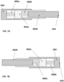
Figure 4: Figure 4A illustrates an example telescope or retractable blade in a first, extended or uncompressed position; andFigure 4B illustrates the blade ofFigure 4A in a second, compressed position. -
Figure 5: Figure 5A shows a front view of an exemplary disconnector and earthing switch having a telescopic blade in the first, on, position;Figure 5B shows a front view of the exemplary disconnector and earthing switch in the second, off or isolation, position (with a compressed telescopic blade); andFigure 5C shows a front view of the exemplary disconnector and earthing switch in the third, earth, position. -
Figure 6: Figure 6A shows a perspective view of an insulating support, andFigure 6B shows a perspective view of the insulating support in combination with an exemplary disconnector and earthing switch. -
Figure 7A and Figure 7B are schematic illustrations of other exemplary telescopic blades. - With reference to
Figure 1 , adevice 100 comprising one ormore switching mechanisms 110 configured to disconnect a power supply from a load and one or more corresponding disconnector and earthingswitches 330 is described. Each disconnector and earthing switch is associated with a respective switching mechanism. In the examples described herein, the disconnector and earthing switch is a 3PS switch (three position disconnector and earthing switch), but it will be understood that the principles of the telescopic blade can be applied to other earthing disconnection switches (e.g. a two position earthing disconnection switch) and to other switch types more generally. -
Device 100 may be a switchgear or any other switching or disconnection device. The device can comprise a circuit breaker, optionally a vacuum circuit breaker VCB, or a load break switch, for example. In some examples,device 100 may comprise a plurality of switching devices, each switching device comprising a plurality of poles. For example,device 100 may be a three-way, three-Pole device. Each pole can be associated with a respective switching mechanism of the one or more switching mechanisms and associated with a respective disconnector and earthing switch of the one or more disconnector and earthing switches. Each of the plurality of switching devices may be optionally implemented as e.g. a vacuum circuit breaker VCB or a load break switch, for example. In the following examples, three switchingmechanisms 110 are shown, but any suitable number of switching mechanisms (of any suitable type, e.g., mechanical, electromechanical and/or solid state) may be used. - The switching mechanisms are provided within a
housing 216. The housing has afirst side wall 216a and asecond side wall 216b and abottom plate 216c. The switching mechanisms shown here are arranged along afirst axis 102 between the first andsecond side walls housing 216. - With further reference to
Figure 1 , each disconnector and earthing switch has adisconnector blade 332 which is pivotably connected, at afirst end 342, to the associated switching mechanism. Thedisconnector blade 332 is the disconnector and earthing switch contact, which facilitates electrical connection of the load to the power supply via the disconnector and earthing switch. In the example ofFigure 1 , thefirst end 342 of the disconnector blade (or contact) is pivotably connected or coupled to a top of a housing enclosing the switching mechanism. Thedisconnector blade 332 also comprises asecond end 334 opposite the first end. - In some examples, each switching mechanism has a fixed contact and a moveable contact, and an actuating mechanism comprising a shaft 214 (extending into the page, here perpendicular to axis 102) and drive
rod 344. The shaft is configured to rotate (here around a rotation axis arranged perpendicular to the first axis 102) to transfer an external input force to move the moveable contact and open or close the switching mechanism. Thedrive rod 344 is connected to theshaft 214 to transfer the rotation of theshaft 214 in response to an external input force into movement of the moveable contact along asecond axis 106 perpendicular to the first axis. The second axis is also referred to herein as the operating axis. The moveable contact is moveable by thedrive rod 344 of the actuating mechanism and is arranged between the fixed contact and theshaft 214 of the actuating mechanism. Each disconnector and earthingswitch 330 is arranged between the active part of the switching mechanism 110 (here the moving and fixed contacts) and theshaft 214 along thesecond axis 106. - In some particular examples, the
switching mechanism 110 is implemented as, or comprises, a vacuum interrupter (or VI). The VI can be implemented as part of a VCB or other circuit breaker, or as part of any other type of switching device (such as a load break switch or LBS). The top contact of the vacuum interrupter VI is the moveable contact, moveable by the actuating mechanism is response to rotation of theshaft 214. With reference toFigure 1 , the fixed contact of the vacuum interrupter VI is fixed to thebottom plate 216c of thehousing 216 via a support plate (not shown). Thebottom plate 216c and first and second sidewalls 216a, 216b at least partially define a switching compartment of theswitchgear 100, 200. The switching compartment described herein is air insulated, however any other insulating medium which fulfils the required dielectric / thermal requirements (such as a vacuum, pressurised air, SF6 (sulphur hexafluoride) or other gaseous dielectric medium, or inert gas) may be provided within the switching compartment. - A housing of the VI covers the fixed and moving contacts and is bolted to the support plate. Column supports formed of an insulating material (not shown) can be bolted between the support plate and the
bottom plate 216c to hold the support plate within the switching compartment of thehousing 216. In this particular example, the VI is mounted on abushing 350. Thebushing 350 is bolted to thebottom plate 216c and is fixed to the support plate with epoxy. - The VI housing here acts as a support for the hinge or pivot point at the
first end 342 of thedisconnector blade 332. The first end of each disconnector blade is pivotably coupled to theswitching mechanism 110. The first end of thedisconnector blade 342 can be pivotably coupled to the switching mechanism between the moveable contact and theshaft 214. In this particular example, the first end of thedisconnector blade 342 is pivotably coupled to a top of the VI housing which surrounds the fixed and moveable contacts of theswitching mechanism 110. - A metallic shield (not shown) can be provided within the VI housing, placed between the moveable contact and the first end of the disconnector blade. The metallic shield acts to help shield the disconnector blade and the hinge/pivotable coupling from any electric field within the vacuum interrupter. As discussed above, the moving contact moves within the VI housing in response to actuation/rotation of the
shaft 214. In particular, rotation of theshaft 214 actuates thedrive rod 344 of the actuating mechanism, pulling the moveable contact along the operating axis towards theshaft 214 and opening theswitch 212. - The disconnector blade of each disconnector and earthing
switch 330 is arranged to pivot around the first end to move between three different positions, as is further illustrated inFigure 2 . - With reference to
Figure 2A , thedisconnector blade 332 is arranged in a first position in which in which the disconnector and earthing switch is closed and the power supply is connected to the load through the disconnector blade. In this first position, current flows through thedevice 100 via theswitching mechanism 110 and thedisconnector blade 332. - In response to user actuation of a direct break mechanism (not shown), the disconnector blade is moved from the first position to a second position, which is shown in
Figure 2B . The direct break mechanism comprises a second shaft and a second actuating mechanism which is operated by rotation of the second shaft. A user can rotate the second shaft by turning or rotating an external handle, and the second actuating mechanism is rotated in response to rotation of the shaft. In this example, the second actuating mechanism is a four-bar crankrocker mechanism 348, but any suitable actuating/driving mechanism may be used. In particular, in response to rotation of the second shaft of the direct break mechanism, the disconnector blade is configured to rotate around the pivot from the first position to the second position, wherein the rotation is towards thesecond side wall 216b of the housing. - In the second position of
Figure 2B , the disconnector and earthing switch is open and the power supply is disconnected from the load (the current path between the load and the power supply through thedisconnector blade 332 is broken). This second, intermediate position is an isolation position in which the disconnector and earthing switch is "off'. Thedisconnector blade 332 can be moved into this "off' or isolation position without a corresponding actuation of the switching mechanisms 110 (i.e., independent of rotation of the shaft 214) in some implementations. However, in other implementations this operation is dependent on the position of theswitching mechanism 110. For example, where the disconnector and earthing switch is an offload 3PS arranged in series with the switching mechanism, the offload 3PS switch can only be operated when the switching mechanism (optionally a VCB) is in an open state. This can be achieved by way of interlock / interlocking mechanisms: the 3PS direct break mechanism will interlock with the switching mechanism to ensure the device is operated as per mechanical interlock requirements. - In response to further user actuation of the second shaft of the direct break mechanism in the same direction of rotation, the disconnector blade is moved from the second position to a third position, which is shown in
Figure 2C . In particular, the disconnector blade is configured to rotate around the pivot from the second position to the third position, wherein the rotation is again towards thesecond side wall 216b of the housing. In the third position, the power supply is disconnected from the load and asecond end 334 of the disconnector blade is electrically connected to anearthing contact 336. Thedisconnector blade 332 can be moved into this earthed position without a corresponding actuation of the switching mechanisms 110 (i.e., independent of rotation of the shaft 214) in some implementations. However, in other implementations, as discussed above, this operation is dependent on the position of theswitching mechanism 110. For example, where the disconnector and earthing switch is an offload 3PS arranged in series with the switching mechanism, the offload 3PS switch can only be operated when the switching mechanism (optionally a VCB) is in the open state. - The disconnector and earthing
switch 330 can thus be activated or controlled independently of theshaft 214 which controls or actuates the moving contact of the switches. In the example described above, thedisconnector blade 332 is coupled to a fixed component (e.g., the housing of the VI) and is therefore decoupled from the actuation of theswitching mechanism 110; in other words, actuation of thedevice 100 viashaft 214 does not actuate the disconnector and earthingswitch 330. However, it will be understood that in other examples the second actuating mechanism (of the disconnector and earthing switch) can be configured such that, when the moving contact is opened byshaft 214 to disconnect the power supply from the load, thedisconnector blade 332 of the disconnector and earthing switch is correspondingly moved to the third, earthed, position. In this way, the current path through eachswitching mechanism 110 is automatically opened in two different locations when the switching mechanism is opened. In other examples, interlock mechanisms can prevent actuation of the direct break mechanism if the switching device is open. - As discussed above,
device 100 comprises a three-position disconnector and earthingswitch 330. It is desirable to provide a disconnector and earthing switch with three positions - on, off (or isolation), and earth - to facilitate in-situ testing of cable integrity and improve the ease of maintenance of the switchgear. It is particularly desirable to combine a three-position disconnector and earthing switch with a compact switchgear, as is discussed below with reference toFigure 3 . - It will be recognised that the device housing 216 (also termed enclosure) is always at ground potential (earthed). In the third position the disconnector plate is also earthed, but in the second, "off" or isolated, position the
disconnector blade 332 is at a live potential. As per IEC62271 standard for metal-enclosed switchgear, an "off" position isolation test should be conducted at 85kVp (or 85 Kilovoltage peak) impulse voltage and 32kV power frequency withstand voltage (maximum rms value of voltage that the device can withstand permanently). However, since the disconnector blade tip (otherwise referred to as the second end 334) is free in air when in the second position, end effects lead to a high intensity electric field being generated at the second end of thedisconnector blade 332. This can lead to dielectric failure of the system and the formation ofelectric breakdown paths 360 between thedisconnector blade 332 and thesecond side wall 216b of the device 100 (as shown inFigure 3A ). - It is therefore desirable that the field intensity should be reduced, and adequate clearance d should be maintained to between the
second side wall 216b and the tip orsecond end 334 of the disconnector blade (seeFigure 3B ) to avoid such dielectric failure between the housing orenclosure 216. Directly increasing the clearance d by moving theside wall 216b away from theswitching mechanism 110 and disconnector and earthingswitch 330 will increase the overall dimensions of thedevice 100, hindering the provision of acompact device 100. It is therefore desirable to increase clearance d and achieve better dielectric performance within a compact device footprint in order to provide a reliable device with a small footprint which can be provided which can more easily and safely tested in-situ (thereby e.g., improve the ease of maintenance). - With reference to
Figure 4 , a telescopic or retractable contact /disconnector blade 432 is described that can help achieve some of the above advantages. The telescopic contact orblade 432 is configured to move between an extended state, shown inFigure 4A , and a compressed or retracted state, shown inFigure 4B . Any suitable arrangement of telescopic or retractable blade can be provided. Thetelescopic blade 432 is a particular embodiment of thedisconnector blade 332 described above. - With particular reference to the example of
Figure 4 , thetelescopic disconnector blade outer contact 404 and aninner contact 402, a portion of the inner contact arranged to slide within the outer contact. These features of theblade inner contact 402 can be inserted into theouter contact 404 and can slide relative to the outer contact. The outer contact comprises thefirst end second end - With further reference to
Figure 4A , theouter contact 404 comprises a guide hole and theinner contact 402 slides within the guide hole. The disconnector blade further comprises acompliant member 406 disposed within the guide hole and configured to bias theinner contact 402 out of the guide hole. In other words, the inner contact can be configured to retract into the outer contact, and the complaint member acts to counter the retraction. Thecompliant member 406 ofFigure 4 is shown as a compression spring, but any other compliant member may be used. The compliant member can be compliant through form and/or material. - As shown in
Figure 4B , in response to an external force F applied in afirst direction 408 and to thesecond end 434 of thedisconnector blade 432, theinner contact 402 is configured to slide in thefirst direction 408 within the guide hole of theouter contact 404. The compliant member compresses in response to the movement of the inner contact in thefirst direction 408. The compressed compliant member is then configured to urge theinner contact 404 away from the outer contact in a direction opposite the first direction. In this way, thedisconnector blade 432 can be in the extended state ofFigure 4A in the absence of a force F. The disconnector blade is configured to move into the compressed state ofFigure 4B in response to an external force. From the compressed state, the disconnector blade is configured to move back to the extended state ofFigure 4A by way of the biasing or urging of thecompliant member 406. - With further reference to
Figure 5 , thedisconnector blade 432 is in the extended state in the first position and the third position (ofFigures 2A ,5A andFigures 2C ,5C , respectively), and thedisconnector blade 432 is in the compressed state in the second position (ofFigures 2B ,5B ). In particular, as can be seen inFigures 4 and5 , in the first "on" position and the third "earthed" position, thedisconnector blade 432 is in the extended state and has an overall length of l_1. In contrast, in the second "off' position, thedisconnector blade 432 is in the compressed (or retracted) state and has an overall length of l_2. The particular lengths l_1 and l_2 can be determined by the device size and application requirements, and the stiffness of thecompliant member 406, but L_2 is less than l_1. In this way, a greater clearance d can be provided for "off' or isolation tests, without increasing the overall footprint of thedevice 100. A reliable device with a small footprint and improved dielectric performance can therefore be provided by use of an disconnector and earthing switch with a telescopic or retractable contact (or disconnector blade), which device can more easily and safely tested in-situ (thereby e.g., improve the ease of maintenance). It will be understood that the telescope blade described herein can also be used with any other form of disconnection and/or earthing switch. - As is also shown in
Figure 5 , thesecond side wall 216b can further comprise an insulatingsupport 500 configured to contact, when the disconnector blade is in the second position (with length l_2), thesecond end 434 of the retracted /compressed disconnector blade 432. This insulatingsupport 500 is discussed further inFigure 6 (Figures 6A, 6B ). - With reference to
Figure 6A , the insulatingsupport 500 comprises an insulatingguide portion 662 configured to cause thedisconnector blade 432 to move from the extended state to the compressed state as the disconnector blade pivots from the first position to the second position. Asection 662a of theguide portion 662 is shaped to gradually decrease the distance between the (fixed length)outer contact 404 and theguide portion 662, thereby causing an increasing displacement of theinner contact 402 of theblade 432 along thefirst direction 408 as the blade pivots (and increasing compression of the compliant member). The reaction force F exerted by theguide portion 662 on thesecond end 434 of the blade is greater than the reaction force from compression of thecompliant member 406, and therefore the disconnector blade retracts. - The insulating
guide portion 662 can be further configured to cause the disconnector blade to move from the compressed state to the extended state as the disconnector blade pivots from the second position to the third position. In this example, asection 662b of the guide portion is shaped to gradually increase the distance between the (fixed length)outer contact 404 and theguide portion 662, thereby allowing theinner contact 402 of theblade 432 to slide in a direction opposite thefirst direction 408 as the blade pivots in response to the biasing or urging of the compliant member 406 (and extension of the compliant member). The reaction force F exerted by theguide portion 662 on thesecond end 434 of the blade is less than the urging force from compression of the compliant member and therefore the disconnector blade extends. - The use of one or more insulating or isolating features such as the insulating
support 500 may improve electrical safety during the isolation, second, position by improving dielectric performance. In particular, the insulatingsupport 500 can help to reduce field end effects at thesecond end 334 of thedisconnector blade 332 and provide a dielectrically better performance compared to a high electric field in air. The insulatingsupport 500 be provided individually, or in combination with one or more other insulating features (including features not described herein). - In some examples, an insulating
sheet 550 may be provided. The insulatingsheet 550 can be formed from any suitable insulating material. The insulatingsheet 550 need not contact thesecond end 434 of thedisconnector blade 432 when the blade is in the second position. The presence of the insulatingsheet 550, even without physical contact, acts as an obstruction to breakdown electrical current paths and can help avoid dielectric failure, thereby improving dielectric performance. - The use of the insulating
support 500 and/or the insulatingsheet 550 on thesecond side wall 216b of the housing / enclosure facilitates use of a three-position disconnector and earthingswitch 330 within a compact device footprint. A more compact, reliable device may therefore be provided by use of the insulating features provided herein. - In the example of
Figure 6B , the disconnector and earthingswitch 330 comprises twodisconnector blades 434, disposed either side of thesecond actuating mechanism 348. In other words, each disconnector and earthing switch can comprise two or more telescopic disconnector blades. By using two disconnector blades, two parallel paths are created for current flow. This can help to improve thermal performance. In such implementations, twoguide portions 662 are also provided; one guide portion is provided for each disconnector blade. However, it will be understood that other arrangements are possible. For example, a single telescopic blade can be provided. In such an implementation, the size/shape of the contacts in the on / off /earth positions can be implemented as e.g. a Jaw contact to facilitate good electrical connection between the blade and the contacts. - The disconnector blade can be operated or actuated by operation of the
second actuating mechanism 348. However, as described above, in this example the disconnector blade will be operated by the second actuating mechanism only when the switching mechanism is open. In other words, the actuating mechanisms are interlocked such a way that the disconnector and earthing switch or 3PS can be operated only when the switching mechanism (such as the VCB) is in the open state. In this example, the second actuating mechanism is implemented as a four-bar crank rocker mechanism (i.e., the telescopic disconnector blade is operated by a four-bar crank rocker mechanism). - In some examples, an
electrical contact 664 is coupled the insulatingsupport 500 and configured to contact the second end(s) 434 of the disconnector blade(s) 432 when the disconnector blade(s) are in the second position. When two disconnector blades are provided, theelectrical contact 664 is configured to be disposed between the second ends 434 of therespective blades 432. Theelectrical contact 664 is disposed between the twoguide portions 662. Theelectrical contact 664 can comprise a partially spherical end. The use of a spherical (i.e., curved) portion at the second end of theelectrical contact 664 acts to reduce or avoid high fields at theelectrical contact 664. Dielectric performance may therefore be further improved. - In the examples described herein, the telescopic contact or blade of the disconnector and earthing
switch 330 comprises two contacts, one moveable relative to the other. However, in other implementations there may be more than two moveable contacts, as is illustrated inFigure 7A . In this example, there are twoinner contacts outer contact 404. Theinner contacts telescopic blade 432. Twocompliant members telescopic blade 432 to the extended state (of e.g.Figure 4A ). The compliant members can be disposed in respective guide holes. In some other examples, more than two inner contacts and corresponding compliant members may be provided. - In another example implementation, shown in
Figure 7B , the inner and outer contacts may be arranged in an alternate manner to form atelescopic blade 432. Theouter contact 404 comprises thesecond end - The
inner contact 402b comprises thefirst end Figure 4 andFigure 7A ). - Other arrangements of a telescopic blade as described herein may also be provided. It should be realised that the foregoing embodiments are not to be construed as limiting and that other variations, modifications and equivalents will be evident to those skilled in the art and are intended to be encompassed by the claims unless expressly excluded by the claim language.
- Moreover, the disclosure of the present application should be understood to include any novel features or any novel combination of features either explicitly or implicitly disclosed herein or in any generalisation thereof. Claims may be formulated to cover any such features and/or combination of such features derived therefrom.
Claims (15)
- A device (100, 200) comprising:one or more switching mechanisms (no) configured to disconnect a power supply from a load; andone or more disconnector and earthing switches (330), each disconnector and earthing switch (330) associated with a respective switching mechanism (110), each disconnector and earthing switch (330) comprising a telescopic disconnector blade (332, 432) having a first end (342, 442) and a second end (334, 434),wherein the disconnector blade (332, 432) is configured to pivot around the first end (342, 442) between three different positions, the three positions comprising:a first position in which the disconnector and earthing switch (330) is closed and the power supply is connected to the load through the disconnector blade (332, 432);a second, isolation, position in which the disconnector and earthing switch (330) is open and the power supply is disconnected from the load; anda third position in which the power supply is disconnected from the load and a second end (334, 434) of the disconnector blade (332, 432) is electrically connected to an earthing contact (336).
- The device (100, 200) of claim 1, wherein the telescopic disconnector blade (332, 432) comprises an outer contact (404) and an inner contact (402), a portion of the inner contact (402) arranged to slide within the outer contact (404).
- The device (100, 200) of claim 2, wherein the outer contact (404) comprises the first end (342, 442) of the disconnector blade (332, 432) and the inner contact (402) comprises the second end (334, 434) of the disconnector blade (332, 432).
- The device (100, 200) of claim 2 or claim 3, wherein the outer contact (404) comprises a guide hole and the inner contact (402) slides within the guide hole,
the disconnector blade (332, 432) further comprising a compliant member (406) disposed within the guide hole and configured to bias the inner contact (402) out of the guide hole. - The device (100, 200) of claim 4, wherein, in response to an external force applied in a first direction (408) and to the second end (334, 434) of the disconnector blade (332, 432), the inner contact (402) is configured to slide in the first direction (408) within the guide hole of the outer contact (404) and the compliant member is configured to bias the inner contact (402) in a direction opposite the first direction (408).
- The device (100, 200) of claim 4 or claim 5, wherein the compliant member is a compression spring.
- The device (100, 200) of any preceding claim, wherein the telescopic disconnector blade (332, 432) is configured to move between an extended state and a compressed state,
wherein the disconnector blade (332, 432) is in the extended state in the first position and the third position, and wherein the disconnector blade (332, 432) is in the compressed state in the second position. - The device (100, 200) of any preceding claim, further comprising a housing (216) having first (216a) and second (216b) side walls, wherein the telescopic disconnector blade (332, 432) is configured to rotate around the pivot from the first position to the second position, wherein the rotation is towards the second side wall (216b) of the housing (216).
- The device (100, 200) of claim 8, wherein the second side wall (216b) comprises an insulating support (500) configured to contact, when the disconnector blade (332, 432) is in the second position, the second end (334, 434) of said disconnector blade (332, 432).
- The device (100, 200) of claim 9, wherein the insulating support (500) comprises a guide portion (662) configured to cause the disconnector blade (332, 432) to move from the extended state to the compressed state as the disconnector blade (332, 432) pivots from the first position to the second position.
- The device (100, 200) of claim 10, wherein the guide portion (662) is further configured to cause the disconnector blade (332, 432) to move from the compressed state to the extended state as the disconnector blade (332, 432) pivots from the second position to the third position.
- The device (100, 200) of any of claims 9 to 11, further comprising an electrical contact (664) coupled to the insulating support (500), the electrical contact (664) configured to contact the second end (334, 434) of the disconnector blade (332, 432) when the disconnector blade (332, 432) is in the second position.
- The device (100, 200) of claim 12, wherein the electrical contact (664) comprises a partially spherical end configured to contact the second end (334, 434) of the disconnector blade (332, 432) when the disconnector blade (332, 432) is in the second position.
- The device (100, 200) of any preceding claim, wherein each disconnector and earthing switch (330) comprises two or more telescopic disconnector blades (332, 432).
- The device (100, 200) of any preceding claim, comprising:
a plurality of switching devices, each switching device comprising a plurality of poles, wherein each pole is associated with a respective switching mechanism of the one or more switching mechanisms (110) and a respective disconnector and earthing switch (330) of the one or more disconnector and earthing switches (330).
Applications Claiming Priority (2)
| Application Number | Priority Date | Filing Date | Title |
|---|---|---|---|
| IN202311016938 | 2023-03-14 | ||
| GB2306482.7A GB2628189A (en) | 2023-03-14 | 2023-05-02 | Disconnector and Earthing Switch with Telescopic Contact |
Publications (2)
| Publication Number | Publication Date |
|---|---|
| EP4432323A1 true EP4432323A1 (en) | 2024-09-18 |
| EP4432323B1 EP4432323B1 (en) | 2025-12-03 |
Family
ID=90364409
Family Applications (1)
| Application Number | Title | Priority Date | Filing Date |
|---|---|---|---|
| EP24162507.8A Active EP4432323B1 (en) | 2023-03-14 | 2024-03-08 | Disconnector and earthing switch with telescopic contact |
Country Status (4)
| Country | Link |
|---|---|
| US (1) | US20240312740A1 (en) |
| EP (1) | EP4432323B1 (en) |
| JP (1) | JP7730391B2 (en) |
| PL (1) | PL4432323T3 (en) |
Citations (3)
| Publication number | Priority date | Publication date | Assignee | Title |
|---|---|---|---|---|
| US20170236657A1 (en) * | 2014-07-01 | 2017-08-17 | Hyundai Heavy Industries Co., Ltd. | Disconnecting switch and earthing switch for gas insulated switchgear |
| EP3288050A1 (en) * | 2015-04-23 | 2018-02-28 | ABB Schweiz AG | Potential transformer isolating device and gas-insulated switchgear |
| CN115332987A (en) * | 2022-09-15 | 2022-11-11 | 上海巴佩开关设备有限公司 | Gas insulation switch cabinet |
-
2024
- 2024-02-27 JP JP2024027346A patent/JP7730391B2/en active Active
- 2024-03-08 PL PL24162507.8T patent/PL4432323T3/en unknown
- 2024-03-08 EP EP24162507.8A patent/EP4432323B1/en active Active
- 2024-03-08 US US18/599,661 patent/US20240312740A1/en active Pending
Patent Citations (3)
| Publication number | Priority date | Publication date | Assignee | Title |
|---|---|---|---|---|
| US20170236657A1 (en) * | 2014-07-01 | 2017-08-17 | Hyundai Heavy Industries Co., Ltd. | Disconnecting switch and earthing switch for gas insulated switchgear |
| EP3288050A1 (en) * | 2015-04-23 | 2018-02-28 | ABB Schweiz AG | Potential transformer isolating device and gas-insulated switchgear |
| CN115332987A (en) * | 2022-09-15 | 2022-11-11 | 上海巴佩开关设备有限公司 | Gas insulation switch cabinet |
Also Published As
| Publication number | Publication date |
|---|---|
| EP4432323B1 (en) | 2025-12-03 |
| JP2024132914A (en) | 2024-10-01 |
| US20240312740A1 (en) | 2024-09-19 |
| PL4432323T3 (en) | 2026-02-16 |
| JP7730391B2 (en) | 2025-08-27 |
Similar Documents
| Publication | Publication Date | Title |
|---|---|---|
| US7829814B2 (en) | Vacuum circuit interrupter grounding assembly | |
| EP1826791B1 (en) | Three-position vacuum interrupter disconnect switch providing current interruption, disconnection and grounding | |
| KR101463374B1 (en) | A switching device and a switchgear | |
| KR101605134B1 (en) | Disconnecting switch and earthing switch for gas insulated switchgear | |
| WO2011073452A1 (en) | A switching device and a switchgear | |
| CN1377515A (en) | A gas insulated switchgear | |
| KR20140021703A (en) | A switching device and a switchgear | |
| CN114765099A (en) | Medium voltage switchgear | |
| GB2286725A (en) | Sequential isolating circuit breaker | |
| GB2628189A (en) | Disconnector and Earthing Switch with Telescopic Contact | |
| EP4432323B1 (en) | Disconnector and earthing switch with telescopic contact | |
| EP4372778A1 (en) | Load break or short-circuit currents switch and electrical equipment incorporating said switch | |
| US3794799A (en) | Gas insulated switch with adjustable overcenter toggle actuator therefore | |
| EP1589625B1 (en) | Gas-insulated switchgear device | |
| CN100428596C (en) | disconnect switch device | |
| CN101040411B (en) | Switchgear with de-interlocked arc limiter | |
| EP4432324A1 (en) | Switchgear architecture | |
| EP4277059A1 (en) | Switchgear equipment for electric power distribution grids | |
| CN110945613A (en) | Isolating switch pole for gas-insulated switchgear | |
| EP0602930A1 (en) | Combined interrupter-disconnect switch blade for high voltage switch | |
| GB2628190A (en) | Switchgear architecture | |
| EP4459653B1 (en) | A switching apparatus for electrical systems | |
| US20250372324A1 (en) | Medium voltage switching apparatus | |
| EP4089704B1 (en) | A medium voltage switching apparatus | |
| EP3876256B1 (en) | Switching device for electric power distribution |
Legal Events
| Date | Code | Title | Description |
|---|---|---|---|
| PUAI | Public reference made under article 153(3) epc to a published international application that has entered the european phase |
Free format text: ORIGINAL CODE: 0009012 |
|
| STAA | Information on the status of an ep patent application or granted ep patent |
Free format text: STATUS: THE APPLICATION HAS BEEN PUBLISHED |
|
| AK | Designated contracting states |
Kind code of ref document: A1 Designated state(s): AL AT BE BG CH CY CZ DE DK EE ES FI FR GB GR HR HU IE IS IT LI LT LU LV MC ME MK MT NL NO PL PT RO RS SE SI SK SM TR |
|
| STAA | Information on the status of an ep patent application or granted ep patent |
Free format text: STATUS: REQUEST FOR EXAMINATION WAS MADE |
|
| 17P | Request for examination filed |
Effective date: 20250318 |
|
| GRAP | Despatch of communication of intention to grant a patent |
Free format text: ORIGINAL CODE: EPIDOSNIGR1 |
|
| STAA | Information on the status of an ep patent application or granted ep patent |
Free format text: STATUS: GRANT OF PATENT IS INTENDED |
|
| INTG | Intention to grant announced |
Effective date: 20250717 |
|
| GRAS | Grant fee paid |
Free format text: ORIGINAL CODE: EPIDOSNIGR3 |
|
| GRAA | (expected) grant |
Free format text: ORIGINAL CODE: 0009210 |
|
| STAA | Information on the status of an ep patent application or granted ep patent |
Free format text: STATUS: THE PATENT HAS BEEN GRANTED |
|
| AK | Designated contracting states |
Kind code of ref document: B1 Designated state(s): AL AT BE BG CH CY CZ DE DK EE ES FI FR GB GR HR HU IE IS IT LI LT LU LV MC ME MK MT NL NO PL PT RO RS SE SI SK SM TR |
|
| P01 | Opt-out of the competence of the unified patent court (upc) registered |
Free format text: CASE NUMBER: UPC_APP_0011040_4432323/2025 Effective date: 20251024 |
|
| REG | Reference to a national code |
Ref country code: CH Ref legal event code: F10 Free format text: ST27 STATUS EVENT CODE: U-0-0-F10-F00 (AS PROVIDED BY THE NATIONAL OFFICE) Effective date: 20251203 Ref country code: GB Ref legal event code: FG4D |
|
| REG | Reference to a national code |
Ref country code: DE Ref legal event code: R096 Ref document number: 602024001468 Country of ref document: DE |
|
| REG | Reference to a national code |
Ref country code: IE Ref legal event code: FG4D |
|
| REG | Reference to a national code |
Ref country code: SE Ref legal event code: TRGR |
|
| REG | Reference to a national code |
Ref country code: NL Ref legal event code: FP |
|
| PGFP | Annual fee paid to national office [announced via postgrant information from national office to epo] |
Ref country code: SE Payment date: 20260219 Year of fee payment: 3 |
|
| PG25 | Lapsed in a contracting state [announced via postgrant information from national office to epo] |
Ref country code: ES Free format text: LAPSE BECAUSE OF FAILURE TO SUBMIT A TRANSLATION OF THE DESCRIPTION OR TO PAY THE FEE WITHIN THE PRESCRIBED TIME-LIMIT Effective date: 20251203 |
|
| REG | Reference to a national code |
Ref country code: LT Ref legal event code: MG9D |
|
| PG25 | Lapsed in a contracting state [announced via postgrant information from national office to epo] |
Ref country code: NO Free format text: LAPSE BECAUSE OF FAILURE TO SUBMIT A TRANSLATION OF THE DESCRIPTION OR TO PAY THE FEE WITHIN THE PRESCRIBED TIME-LIMIT Effective date: 20260303 |
|
| PGFP | Annual fee paid to national office [announced via postgrant information from national office to epo] |
Ref country code: DE Payment date: 20260219 Year of fee payment: 3 |
|
| PG25 | Lapsed in a contracting state [announced via postgrant information from national office to epo] |
Ref country code: HR Free format text: LAPSE BECAUSE OF FAILURE TO SUBMIT A TRANSLATION OF THE DESCRIPTION OR TO PAY THE FEE WITHIN THE PRESCRIBED TIME-LIMIT Effective date: 20251203 Ref country code: FI Free format text: LAPSE BECAUSE OF FAILURE TO SUBMIT A TRANSLATION OF THE DESCRIPTION OR TO PAY THE FEE WITHIN THE PRESCRIBED TIME-LIMIT Effective date: 20251203 |
|
| PGFP | Annual fee paid to national office [announced via postgrant information from national office to epo] |
Ref country code: AT Payment date: 20260301 Year of fee payment: 3 |
|
| PG25 | Lapsed in a contracting state [announced via postgrant information from national office to epo] |
Ref country code: RS Free format text: LAPSE BECAUSE OF FAILURE TO SUBMIT A TRANSLATION OF THE DESCRIPTION OR TO PAY THE FEE WITHIN THE PRESCRIBED TIME-LIMIT Effective date: 20260303 |
|
| PGFP | Annual fee paid to national office [announced via postgrant information from national office to epo] |
Ref country code: PL Payment date: 20260219 Year of fee payment: 3 |
|
| PG25 | Lapsed in a contracting state [announced via postgrant information from national office to epo] |
Ref country code: LV Free format text: LAPSE BECAUSE OF FAILURE TO SUBMIT A TRANSLATION OF THE DESCRIPTION OR TO PAY THE FEE WITHIN THE PRESCRIBED TIME-LIMIT Effective date: 20251203 |
|
| PG25 | Lapsed in a contracting state [announced via postgrant information from national office to epo] |
Ref country code: BG Free format text: LAPSE BECAUSE OF FAILURE TO SUBMIT A TRANSLATION OF THE DESCRIPTION OR TO PAY THE FEE WITHIN THE PRESCRIBED TIME-LIMIT Effective date: 20251203 |