EP4432054A1 - Input device - Google Patents
Input device Download PDFInfo
- Publication number
- EP4432054A1 EP4432054A1 EP22892553.3A EP22892553A EP4432054A1 EP 4432054 A1 EP4432054 A1 EP 4432054A1 EP 22892553 A EP22892553 A EP 22892553A EP 4432054 A1 EP4432054 A1 EP 4432054A1
- Authority
- EP
- European Patent Office
- Prior art keywords
- control button
- button
- control
- type
- buttons
- Prior art date
- Legal status (The legal status is an assumption and is not a legal conclusion. Google has not performed a legal analysis and makes no representation as to the accuracy of the status listed.)
- Pending
Links
Images











Classifications
-
- A—HUMAN NECESSITIES
- A63—SPORTS; GAMES; AMUSEMENTS
- A63F—CARD, BOARD, OR ROULETTE GAMES; INDOOR GAMES USING SMALL MOVING PLAYING BODIES; VIDEO GAMES; GAMES NOT OTHERWISE PROVIDED FOR
- A63F13/00—Video games, i.e. games using an electronically generated display having two or more dimensions
- A63F13/20—Input arrangements for video game devices
- A63F13/24—Constructional details thereof, e.g. game controllers with detachable joystick handles
-
- A—HUMAN NECESSITIES
- A63—SPORTS; GAMES; AMUSEMENTS
- A63F—CARD, BOARD, OR ROULETTE GAMES; INDOOR GAMES USING SMALL MOVING PLAYING BODIES; VIDEO GAMES; GAMES NOT OTHERWISE PROVIDED FOR
- A63F13/00—Video games, i.e. games using an electronically generated display having two or more dimensions
- A63F13/40—Processing input control signals of video game devices, e.g. signals generated by the player or derived from the environment
-
- G—PHYSICS
- G05—CONTROLLING; REGULATING
- G05G—CONTROL DEVICES OR SYSTEMS INSOFAR AS CHARACTERISED BY MECHANICAL FEATURES ONLY
- G05G1/00—Controlling members, e.g. knobs or handles; Assemblies or arrangements thereof; Indicating position of controlling members
- G05G1/02—Controlling members for hand actuation by linear movement, e.g. push buttons
-
- G—PHYSICS
- G06—COMPUTING OR CALCULATING; COUNTING
- G06F—ELECTRIC DIGITAL DATA PROCESSING
- G06F3/00—Input arrangements for transferring data to be processed into a form capable of being handled by the computer; Output arrangements for transferring data from processing unit to output unit, e.g. interface arrangements
- G06F3/01—Input arrangements or combined input and output arrangements for interaction between user and computer
- G06F3/02—Input arrangements using manually operated switches, e.g. using keyboards or dials
- G06F3/0202—Constructional details or processes of manufacture of the input device
-
- G—PHYSICS
- G06—COMPUTING OR CALCULATING; COUNTING
- G06F—ELECTRIC DIGITAL DATA PROCESSING
- G06F3/00—Input arrangements for transferring data to be processed into a form capable of being handled by the computer; Output arrangements for transferring data from processing unit to output unit, e.g. interface arrangements
- G06F3/01—Input arrangements or combined input and output arrangements for interaction between user and computer
- G06F3/02—Input arrangements using manually operated switches, e.g. using keyboards or dials
- G06F3/0202—Constructional details or processes of manufacture of the input device
- G06F3/0219—Special purpose keyboards
-
- A—HUMAN NECESSITIES
- A63—SPORTS; GAMES; AMUSEMENTS
- A63F—CARD, BOARD, OR ROULETTE GAMES; INDOOR GAMES USING SMALL MOVING PLAYING BODIES; VIDEO GAMES; GAMES NOT OTHERWISE PROVIDED FOR
- A63F13/00—Video games, i.e. games using an electronically generated display having two or more dimensions
- A63F13/20—Input arrangements for video game devices
- A63F13/22—Setup operations, e.g. calibration, key configuration or button assignment
-
- A—HUMAN NECESSITIES
- A63—SPORTS; GAMES; AMUSEMENTS
- A63F—CARD, BOARD, OR ROULETTE GAMES; INDOOR GAMES USING SMALL MOVING PLAYING BODIES; VIDEO GAMES; GAMES NOT OTHERWISE PROVIDED FOR
- A63F13/00—Video games, i.e. games using an electronically generated display having two or more dimensions
- A63F13/20—Input arrangements for video game devices
- A63F13/24—Constructional details thereof, e.g. game controllers with detachable joystick handles
- A63F13/245—Constructional details thereof, e.g. game controllers with detachable joystick handles specially adapted to a particular type of game, e.g. steering wheels
-
- A—HUMAN NECESSITIES
- A63—SPORTS; GAMES; AMUSEMENTS
- A63F—CARD, BOARD, OR ROULETTE GAMES; INDOOR GAMES USING SMALL MOVING PLAYING BODIES; VIDEO GAMES; GAMES NOT OTHERWISE PROVIDED FOR
- A63F13/00—Video games, i.e. games using an electronically generated display having two or more dimensions
- A63F13/90—Constructional details or arrangements of video game devices not provided for in groups A63F13/20 or A63F13/25, e.g. housing, wiring, connections or cabinets
- A63F13/98—Accessories, i.e. detachable arrangements optional for the use of the video game device, e.g. grip supports of game controllers
-
- G—PHYSICS
- G05—CONTROLLING; REGULATING
- G05G—CONTROL DEVICES OR SYSTEMS INSOFAR AS CHARACTERISED BY MECHANICAL FEATURES ONLY
- G05G1/00—Controlling members, e.g. knobs or handles; Assemblies or arrangements thereof; Indicating position of controlling members
- G05G1/01—Arrangements of two or more controlling members with respect to one another
Definitions
- the present disclosure relates to an input device.
- PTL 1 described below discloses an input device used for control of a game console.
- Input devices used for applications such as games are used by users to input control signals to the applications.
- An object of the present disclosure is to provide a new input device that can make control comfortable for users who have difficulty in feeling comfortable controlling existing input devices.
- An input device includes a body, a first control button having a top surface portion for placing a hand and attached to the body, and a plurality of second control buttons arranged along an outer edge of the first control button and attached to the body. Outer circumferential portions of the plurality of second control buttons extend outward beyond an outer circumferential edge of the body. This can make control of the input device comfortable for users who have difficulty in feeling comfortable controlling existing input devices.
- the present disclosure typically relates to a computer eco-system including an aspect of consumer electronics (CE) device networks not limited to computer game networks.
- the system in the present specification can include server and client components that are connected via a network such that data is exchanged between the client and server components.
- the client components can include one or more pieces of computing equipment such as game consoles such as Sony PlayStation (registered trademark), game consoles of Microsoft (registered trademark), Nintendo (registered trademark), or the like; virtual reality (VR) headsets, augmented reality (AR) headsets, portable televisions (smart televisions, Internet-enabled televisions, etc.), or portable computers (mobile equipment such as laptop personal computers or tablet terminals, additional equipment mentioned later such as smartphones).
- game consoles such as Sony PlayStation (registered trademark), game consoles of Microsoft (registered trademark), Nintendo (registered trademark), or the like
- VR virtual reality
- AR augmented reality
- portable televisions smartt televisions, Internet-enabled televisions, etc.
- portable computers mobile equipment such as laptop
- Linux (registered trademark) or Unix (registered trademark) operating systems or operating systems manufactured by Microsoft (registered trademark), Apple (registered trademark), or Google (registered trademark) can be adopted.
- These operating environments can be used for executing one or more browsing programs such as browsers provided by Microsoft (registered trademark), Google (registered trademark), or Mozilla (registered trademark) that make it possible to access Web sites hosted by Internet servers mentioned later.
- an operating environment according to the present principles can be used for executing one or more computer game programs.
- Servers and/or gateways can include one or more processors (those that are configured to allow the servers to receive and transmit data on networks such as the Internet).
- clients and servers can also be connected by a local intranet or a virtual private network.
- Servers and controllers can be embodied by game consoles such as Sony PlayStation (registered trademark), personal computers, or the like.
- servers and clients can include network infrastructures for reliability and security such as firewalls, load balancers, transitory storage devises, or proxies.
- One or more servers can form an apparatus that implements a method of providing safe communities like online social websites to network members.
- Processors include single-chip or multi-chip processors that can execute logic by various types of line such as address lines, data lines, or control lines, registers, and shift registers.
- a first illustrative apparatus included in the system 10 is a consumer electronics (CE) device such as an audio video device (AVD) 12 not limited to an Internet-enabled television with a television tuner (equivalently, a set top box that controls a television).
- CE consumer electronics
- the AVD 12 may be a computerized Internet-enabled device such as a smartphone, a tablet computer, a laptop computer, a head mounted display (HMD), a wearable computerized apparatus, a music player, a headphone, or a device that can be transplanted onto skin.
- HMD head mounted display
- the AVD 12 is configured to be compliant with the principles of this document (e.g. communicate with another CE devise in order to be compliant with the principles of this document, execute logic described in this document, and execute any other functions and/or operations described in this document).
- the AVD 12 can be established with some or all of constituent elements depicted in FIG. 1 .
- the AVD 12 can include one or more displays 14.
- the displays 14 may be implemented by high-definition or ultra-high-definition flat screens with definition equal to or higher than "4K," and may support touch control for receiving user input signals via touch control on the displays.
- the AVD 12 can include one or more speakers 16 for outputting sound, and at least one additional input devise 18.
- the input devise 18 is a sound receiver, a microphone, or the like for inputting audible commands to the AVD 12 for controlling the AVD 12.
- the illustrative AVD 12 can also include one or more network interfaces 20.
- the network interfaces 20 Under the control of one or more processors 24, the network interfaces 20 perform communication via at least one network 22 such as the Internet, a wide area network (WAN), or a local area network (LAN). Accordingly, although this is not the sole example, the interface 20 may be a Wi-Fi transceiver which is an example of a wireless computer network interface, and, for example, may be a mesh network transceiver. It will be understood that the processors 24 controls the AVD 12, e.g. controls the displays 14 to present images thereon, and receives inputs from the displays 14, in order to be compliant with the principles of this document including other elements of the AVD 12 described in the present specification. Furthermore, it should be noted that the network interfaces 20 may be other appropriate interfaces such as a wired or wireless modem or router, a wireless telephone transceiver, or a Wi-Fi transceiver mentioned above.
- the AVD 12 can also include one or more input/output ports 26 such as a high-definition multi-media interface (HDMI (registered trademark)) port or a universal serial bus (USB) port for physical connection with other CE devises, and/or a headphone port for connecting a headphone to the AVD 12, and presenting sound from the AVD 12 to a user via the headphone.
- the input/output ports 26 may be connected to an audio video content cable or satellite source 26a by wired or wirelessly.
- the source 26a may be a separate or integrated set top box or a satellite receiver.
- the source 26a may be a game console or a disc player on which content is stored.
- the source 26a in a case where it is implemented as a game console can include some or all of constituent elements mentioned later in relation to a CE devise 48.
- the AVD 12 may further include one or more computer memories 28 such as a non-transitory signal disc-based or solid state storage.
- the AVD 12 may be included in the chassis of the AVD as a standalone device, or may be embodied as a personal video recording device (PVR) or a video disc player inside or outside the chassis of the AVD for reproducing AV programs or as a removable memory medium or a server mentioned later.
- PVR personal video recording device
- a video disc player inside or outside the chassis of the AVD for reproducing AV programs or as a removable memory medium or a server mentioned later.
- the AVD 12 can receive geographical positional information from a satellite or a mobile phone base station, and provide the information to the processors 24, and/or the AVD 12 can include a mobile phone receiver, a GPS receiver, and/or a position or position receiver such as an altimeter 30 that are arranged in relation to the processors 24, and configured to decide altitudes, but this is not the sole example.
- the components 30 can also decide the three-dimensional position and orientation of the AVD 12 by an inertial measurement unit (IMU) typically including a combination of an accelerometer, a gyroscope, and a magnetometer, or can also be implemented by an event-based sensor.
- IMU inertial measurement unit
- the AVD 12 can include one or more cameras 32.
- the cameras 32 are a digital camera such as an infrared camera or a web camera, an event-based sensor, and/or a camera that can be integrated into the AVD 12, and controlled by the processors 24, and collects photographs/images, and/or videos according to the principles of this document.
- the AVD 12 may include each of a Bluetooth transceiver 34 and another NFC element 36 for communication with another apparatus that uses the Bluetooth (registered trademark) and/or near field communication (NFC) technologies. Examples of the NFC element include a radio frequency identification (RFID) element.
- RFID radio frequency identification
- the AVD 12 can include one or more auxiliary sensors 38 that provide inputs to the processors 24 (e.g. a motion sensor such as an accelerometer, a gyroscope, a cyclometer, or a magnetic sensor, an infrared (IR) sensor, an optical sensor, a speed and/or cadence sensor, an event-based sensor, a gesture sensor (e.g. for sensing gesture commands)).
- the AVD 12 may include an over-the-air (OTA) television broadcast port 40 for receiving OTA television broadcasts to provide inputs to the processors 24.
- OTA over-the-air
- the AVD 12 can include also an infrared (IR) transmitter, an IR receiver, and/or an IR transceiver 42 such as an IR data association (IRDA) device.
- IR infrared
- a battery (not depicted) may be provided for supplying electric power to the AVD 12, and similarly may be a mobile environment power generating apparatus that can convert kinetic energy into electric power for charging a battery and/or supplying electric power to the AVD 12.
- a graphics processing unit (GPU) 44 and a field programmable gate array (FPGA) 46 may be included.
- One or more tactile sense generators 47 may be provided for generating tactile signals that can be sensed by a human holding or touching a device.
- the system 10 may include one or more other types of CE devise.
- a first CE devise 48 may be a computer game console that can be used to send sounds and videos of a computer game to the AVD 12 via a command directly sent to the AVD 12 and/or via a server mentioned later
- a second CE devise 50 may include components similar to those of the first CE devise 48.
- the second CE devise 50 may be configured as a computer game controller to be controlled by a player, or may be configured as an HMD to be worn by a player.
- At least one server 52 mentioned before includes at least one server processor 54, at least one tangible computer-readable storage medium 56 such as a disc-based or solid state storage, and at least one network interface 58 that enables communication with another apparatus in FIG. 1 via the network 22 under the control of the server processor 54, and can make easier communication between the server and a client apparatus according to the principles of this document actually.
- the network interface 58 may be, for example, a wired or wireless modem or router, a Wi-Fi transceiver, or another appropriate interface like a wireless telephone transceiver, for example.
- the server 52 may be an Internet server or an entire server "firm,” and can include and execute "cloud” functions such that devices of the system 10 can access a "cloud" environment via the server 52 in an illustrative embodiment for a network game application, for example.
- the server 52 may be realized by one or more game consoles or another computer in the same room as another apparatus depicted in FIG. 1 or near the room.
- Constituent elements depicted in the following figures include some or all of constituent elements depicted in FIG. 1 , in some cases.
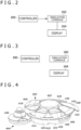
- FIG. 2 depicts that a controller 200 according to the principles of this document can be used for inputting control signals to a computer simulation console 202 in order to control display on a display 204 of a computer simulation executed on the console 202.
- the display 204 may be a television, an HMD (Head Mounted Display), or another display.
- FIG. 3 is a diagram depicting that the controller 200 according to the present principles inputs a control signal to a computer simulation server 300 that can be implemented by the server 52 in FIG. 2 , for example, and a computer simulation is executed on the server 300, and is streamed to the display 204.
- the simulation may be directly streamed to the display 204 by the server 300, or may be streamed via the simulation console 202 depicted in FIG. 2 .
- controller 200 depicted in FIG. 2 and FIG. 3 is explained with reference to FIG. 4 to FIG. 10 .
- Individual constituent elements of the controller 200 mentioned later may be formed of injection-molded plastics, inkjet-printed plastics including ones that can be manufactured by a manufacturer or an end user, composite materials, metals, plastics which are combinations of them, or the like.
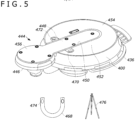
- a base portion 400 having a circular peripheral portion supports, at its top portion, a plurality of control buttons including a central control (CC) button 402.
- the CC button 402 can operate to send signals to a computerized apparatus such as the server 300 in FIG. 3 or the simulation console 202 in FIG. 2 when the apparatus is communicating with the controller through a wire and/or wirelessly.
- the CC button 402 in the non-limiting example depicted in the figure may have a circular, and gently projection top surface portion.
- the shape of the CC button 402 may be another shape.
- the CC button 402 has two functions as a normal control button, and an armrest or a palm rest. Note that in a case where the CC button 402 is used as an armrest or a palm rest, the CC button 402 may have a lock mechanism for stopping upward/downward movement.
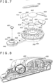
- a circular light-emitting section 403 (see FIG. 7 ) is arranged around the central button, and is devised such that the light-emitting section can be seen from any direction.
- One or more light emitting diodes (LEDs) or other light sources may be arranged under the transparent or semi-transparent portion 403, and light to be propagated through the portion 403 may be provided.
- a plurality of peripheral control (PC) buttons 404 surround the circular light-emitting section 403, and accordingly surround the CC button 402 as depicted in the figure.
- the PC buttons 404 completely surround the CC button 402 leaving only small spaces between the adjacent PC buttons 404.
- the PC buttons 404 may have mutually different shapes, sizes, colors, and textures. Some of the PC buttons 404 may have identical colors and textures, when desired.
- Each PC button can operate to transmit signals to a computerized apparatus when the computerized apparatus is communicating with the apparatus.
- one or more of the PC buttons 404 may have outer edge portions overhanging the base portion 400 (extending radially outward beyond the peripheral portion) in order to make it easier to replace the buttons with one finger or an elbow. Accordingly, end portions of the tops of the PC buttons may have shapes protruding from an end portion of the controller base portion 400.
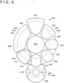
- a first PC button 406 in a top view includes, when seen from above, a curved inner circumferential portion 408 closest to the CC button 402, and side surfaces 410 that spread outward, and are curved slightly or straight toward an outer circumferential portion 412.
- the outer circumferential portion 412 is larger (longer) than the inner circumferential portion 408.
- the first PC button 406 has a flat top surface portion or a gently projection top surface portion, and may incline from the middle of the top surface portion in dimensions in both the radial direction (the dimension from the middle of the controller toward the outer edge of the controller) and the orientation direction.
- the second and third PC buttons 414 and 416 have upwardly-inclined outside regions 418 and 420, respectively.
- the inner circumferences and the outer circumferences of the second and third PC buttons 414 and 416 have substantially the same lengths.
- Side surfaces 422 of the second and third PC buttons 414 and 416 may be straight, and form race-track-like circumferential edges of the respective PC buttons together with the inner circumferences and the outer circumferences.
- the side surfaces 422 may be gently projection, and form egg-shaped outer circumferences of the respective PC buttons together with the inner circumferences and the outer circumferences.
- the second and third PC buttons 414 and 416 have the upwardly-inclined outside regions 418 and 420, respectively, and these essentially represent discontinuity of the inclinations at ends of downwardly-inclined inside regions.
- a fourth PC button 424 is positioned next to the third PC button 416, and may have the same configuration as the second and third buttons 414 and 416 in terms of the same top surface portion shape, and upwardly-inclined outside region 426.
- a fifth PC button 428 is positioned next to the fourth PC button 424, and may have a contour that is flat or gently and continuously downwardly-inclined from a projection inner circumferential surface 430 of the fifth PC button 428 closest to the CC button to a projection outer circumferential surface 432.
- a sixth PC button 434 is positioned next to the fifth PC button 428, and may be configured with an identical shape as the fifth PC button 428, but may have a size larger than the fifth PC button 428.
- a seventh PC button 436 may be positioned between the sixth PC button 434 and the first PC button 406 as depicted in the figure, and may be larger than other PC buttons.
- the seventh PC button 436 has a recess inner circumferential surface 438 in contrast to other PC buttons that may have projection inner circumferential surfaces, and the seventh PC button 436 may have straight side surfaces 440 that spread outward extending from the inner circumferential surface 438 to a projection outer circumferential surface 442.
- buttons 404 may be freely removably engaged with the base portion 400.
- each PC button 404 can removably engage with each pad 700 on the base portion 400.
- the removable engagement may be friction or snap-fits between the PC buttons 404 and the respective pads 700, or the engagement may be magnetic engagement as depicted in FIG. 9 and FIG. 10 .
- each of the buttons 402 and 404 may be coupled to a ferromagnetic plate 900 (steel, etc.) such that the button engages with a magnet 902 in each pad 700 magnetically. It is understood that the magnets are positioned on the buttons, and the ferromagnetic plates are positioned on the pads of the base portion, in some cases.
- button covers can be moved to different basic controls on the base portion 400.
- functions of the controls themselves also can be defined by a user.
- buttons 402 and 404 may have a unique color different from other buttons.
- some buttons, the buttons 402 and 404 may have a first color, and one or more other buttons may have colors different from the first color.
- all the second to fourth buttons 414, 416, and 424 may have the same color, and the color may be different from the colors of the other buttons.
- One or more buttons may have braille patterns formed thereon projecting on top portions of the buttons by embossing or another method in order to help visually impaired people identify the buttons.
- buttons 402 and 404 to be touched by a user may have a unique texture different from other buttons.
- some buttons, the buttons 402 and 404 may have a first texture, and one or more other buttons may have textures different from the first texture.
- all the second to fourth buttons 414, 416, and 424 may have the same texture, and the texture may be different from the textures of the other buttons.
- the first texture may be a smooth texture
- the second texture may be a coarse texture, a lined texture, a dimpled texture, or another tactilely distinguishable texture.
- buttons shapes other than those described above also can be used.
- a plurality of buttons different from those described above also can be used. This recognition is part of the invention principles of this document, and does not constitute part of the technologies in the past.
- the control portion 446 may be a joystick-type input devise.
- the "north" of the control portion 446 may be defined at the factory, or may be defined by a user. For example, the "north" may be defined such that a user's need is met most by using a user interface that permits the user to define which radial direction of the ASU 444 should be defined as the "north.”
- An additional control key 447 may be provided next to the control portion 446 in the ASU 444 as depicted in the figure for control for generating additional control signals for game play.
- the ASU 444 includes a flat-plate-like platform including a slide 448.
- the slide 448 faces a parallel side surface 450 of the base portion 400, and slidably engages with a receiving portion 452 of the base portion 400 (e.g. slidably engages with a flat-plate-like base-portion plate 454).
- the receiving portion 452 is on the bottom surface of the base portion 400, and the control buttons 402 and 404 are at the top portion of the base portion.
- the flat platform may include, at one end of the slide 448, a disc-like support portion 456 to which the control portion 446 is attached rotatably.
- both the support portion 456 and the control portion 446 are circular, and have substantially the same diameter.
- the support portion 456 and the slide 448 may be formed of an integrated material such as a plastic.
- a separate structure combining an anti-slip rubber part and a plastic part can also be adopted.
- the control portion 446 can be controlled to generate signals to a computerized apparatus.
- the control portion 446 can include a point-and-click apparatus which is, in the example depicted in the figure, a button 458 and a button cover 460 to be pressed down to generate signals.
- the button 458 is attached on a rotatable ball 462 in a round socket 464 that protrudes upward at the center of the control portion 446.
- the button cover 460 has a relatively large size, and may have a strap hole for receiving a fastening strap or a carrying strap formed at its top portion.
- all connectors 466 (see FIG. 4 ) not limited to a USB connector may be arranged on a side opposite to the analog stick unit in order to avoid interference of a cable in control of the analog stick by a user. Since a USB cable is the thickest in cables that are expected to be connected to the equipment and may influence the posture at the time of use, the USB connector may be arranged on a side 180 degrees opposite to the analog stick.
- a flexible buckle attachment 468 (see FIG. 5 ) formed of a soft material such as silicon, rubber, or an elastic member can be attached to the rear surface of the base portion 400. Since, due to its flexibility, the buckle attachment deforms along an attached portion such as a user's foot or arm, or an arm of a wheelchair, stable attachment is possible.
- two screw holes 470 may be formed through the bottom surface or another surface of the base portion 400.
- Each connector 472 may pass through a hole 474 of the attachment 468, engage with a hole 470 of the base portion 400, and hold the base portion and the attachment together.
- Another attachment like a tripod 476 also can be engaged with the base portion 400 similarly.
- FIG. 11 depicts an alternative button layout in which eight peripheral buttons 1100 surround a round center button 1102.
- the peripheral buttons 1100 may have identical shapes and sizes, and, in the example depicted in the figure, may have the shape of the first PC button 406 depicted in FIG. 4 .
- buttons may be arranged left-right symmetrically along a circumferential edge portion of the base portion.
- FIG. 12 depicts an alternative button layout in which peripheral buttons 1200 surround a round center button 1202.
- Some or all of the peripheral buttons 1200 may have identical shapes such as circular shapes and identical sizes.
- four of the peripheral buttons 1200 are round, one of the round peripheral buttons is smaller than the other three peripheral buttons, and one (denoted with 1204) of the peripheral buttons is oval, and curved in the azimuth direction as depicted in the figure.
- Two (denoted with 1206) of the peripheral buttons may be small, flat, and straight buttons.
- FIG. 13 is a view depicting the controller 200 according to the principles of this document engaged with an attachment 1302.
- the attachment 1302 has flexibility and is a leg band or a strap that can fix the controller 200 to a leg or another portion of a user 1304.
- attachment can be performed effectively by using fixing members and screw holes at the base portion of the controller as mentioned above such that the controller 200, when attached to a thigh of the user, faces only one or two directions.
- two controllers are provided, one may be configured for optimal control by one hand of a user, and the other may be configured for optimal control by the other hand of the user.
- FIG. 14 is a perspective view of a controller 2000
- FIG. 15 is a plan view of the controller 2000.
- the controller 2000 depicted in FIG. 14 and FIG. 15 also can be used for inputting control signals to the console 202 or the server 300 similarly to the controller 200 mentioned above.
- Individual constituent elements of the controller 2000 mentioned later also may be formed of resin such as plastic, metal, a composite material of them, or the like.
- the X1 direction and the X2 direction along the X axis (the direction in which a body 2100 and a stick unit 2200 mentioned later are arrayed) depicted in FIG. 14 and the like are treated as the right direction and the left direction, respectively.
- the Y1 direction and the Y2 direction along the Y axis perpendicular to the X axis are treated as the forward direction and the backward direction, respectively.
- the Z1 direction and the Z2 direction along the Z axis (the direction of extension of a control stick 2220 mentioned later) perpendicular to the X axis and the Y axis depicted in FIG. 3 and the like are treated as the upward direction and the downward direction, respectively.
- these directions and arrangement positions are specified for explaining the shapes and relative positional relations of elements (parts, members, and portions) of the controller 2000, and are not for limiting the posture of the controller 2000.
- the controller 2000 has the body 2100 (base portion) which is the body of the controller 2000, and on which a plurality of control buttons are arranged, and a stick unit 2200 (analog stick unit) connected to the body 2100.
- the stick unit 2200 is arranged next to the body 2100.
- the body 2100 and the stick unit 2200 may be arranged on a predetermined horizontal surface such as a floor, a desk, or a thigh of a user.
- the stick unit 2200 has a slide portion 2210 that extends in the leftward/rightward direction (the direction perpendicular to the upward/downward direction), and is connected to the body 2100.
- the stick unit 2200 has a dome-like shape that bulges upward as a whole, and has the control stick 2220 at a top portion positioned at its central portion.
- the body 2100 has, at its bottom portion, a housing recess portion (not depicted) that houses the slide portion 2210, and the slide portion 2210 can move in its direction of extension relative to the housing recess portion. Thereby, the stick unit 2200 can move in the direction of extension of the slide portion 2210 relative to the body 2100.
- the stick unit 2200 includes a circuit board (not depicted) for detecting motions of the control stick 2220, and the body 2100 includes a first circuit board 2190 (see FIG. 23 ) and a plurality of second circuit boards 2380 (see FIG. 22B and FIG. 23 ) for detecting press-control of a plurality of control buttons attached to the body 2100.
- the first circuit board 2190 and the plurality of second circuit boards 2380 are electrically connected by wires which are not depicted.
- the body 2100 of the controller 2000 has thereon a first control button (central control button) 2110 which serves as a control portion to be controlled by a user, and a plurality of second control buttons 2120 (peripheral control buttons) (type-A to type-E second control buttons 2120A to 2120E mentioned later) that serve as control portions to be controlled by the user.
- the body 2100 is circular in a plan view, and the first control button 2110 and the plurality of second control buttons 2120 are attached onto the body 2100.
- the first control button 2110 also is circular in a plan view.
- the first control button 2110 is provided at a central portion of the body 2100. As depicted in FIG.
- the first control button 2110 has a top surface portion larger than the plurality of second control buttons 2120, and a central portion of the top surface portion is formed in a dome-like shape that bulges upward gently. With such a size and a shape of the first control button 2110, it is easier for a user to place her/his hand on the first control button 2110.
- the first control button 2110 can contribute as a button for placing a hand of a user.
- the plurality of second control buttons 2120 are arranged along the outer circumferential edge C2 of the first control button 2110.
- the plurality of second control buttons 2120 are arrayed in an arc-like shape along the outer circumferential edge C2 of the first control button 2110 in state where the plurality of second control buttons 2120 are attached to the body 2100.
- Each second control button 2120 has an arc-like outer circumferential edge 2121 and inner circumferential edge 2122.
- the outer circumferential edges 2121 of the second control buttons 2120 are arranged outside the body 2100 beyond an outer circumferential edge C1 of the body 2100 in a state where the second control buttons 2120 are attached to the body 2100.
- the inner circumferential edges 2122 of the second control buttons 2120 are arranged on the inner side of the outer circumferential edge C1 of the body 2100 in a state where the second control buttons 2120 are attached to the body 2100.
- the plurality of second control buttons 2120 are formed in such tapered shapes that the lengths of the outer circumferential edges 2121 of the plurality of second control buttons 2120 are greater than the lengths of the inner circumferential edges 2122, and the widths of the plurality of second control buttons 2120 in the circumferential direction of the body 2100 gradually decrease from the outer circumferential edges 2121 toward the inner circumferential edges 2122.
- the side edges of the second control buttons 2120 extend toward the middle of the body 2100 along the radial direction of the body 2100. With such shapes of the plurality of second control buttons 2120, clearances between pairs of adjacent second control buttons 2120 can be made uniform in a state where the plurality of second control buttons 2120 are attached to the body 2100.
- each outer circumferential edge 2121 of the plurality of second control buttons 2120 is arranged outside the outer circumferential edge C1 of the body 2100, and forms an arc-like outer edge along the outer circumferential edge C1.
- Top surface portions of the plurality of second control buttons 2120 have openings H1 that are formed therethrough, and mark members 2400 (see FIG. 26A and FIG. 26B ) mentioned later are attached to the openings H1.
- the opening H1 is formed at a position closer to the outer circumferential edge 2121 of the second control button 2120 than to a central portion of the second control button 2120.
- the openings H1 are formed at the central positions of the second control buttons in the widthwise direction (the circumferential direction of the body 2100). Portions of the openings H1 are formed through outer circumferential portions 2131 of the second control buttons 2120.
- the inner circumferential edges 2122 of the type-A to type-D second control buttons 2120A to 2120D in the plurality of second control buttons 2120 are recess in arc-like shapes along the outer circumferential edge C2 of the first control button 2110.
- the inner circumferential edges 2122 of the type-A to type-D second control buttons 2120A to 2120D are arranged outside the outer circumferential edge C2 of the first control button 2110, and form an arc-like inner edge along the outer circumferential edge C2.
- the plurality of second control buttons 2120A have the outer circumferential portions 2131 including the outer circumferential edges 2121.
- the outer circumferential portions 2131 extend outward beyond the outer circumferential edge C1 of the body 2100 in a state where the second control buttons 2120 are attached to the body 2100.
- the top surface portion which is a control surface of the second control button 2120A can be formed large. For example, in a case where control buttons are small and their surfaces are small as on existing input devices, it is difficult for users to control the control buttons, in some cases.
- the top surface portion of the second control button 2120A by forming the top surface portion of the second control button 2120A large, it becomes easier to press-control the button, and control of the controller 2000 including the second control button 2120A can be made comfortable for users who have difficulty in feeling comfortable controlling existing input devices.
- bottom surface portions e.g. a bottom surface portion 2124A in FIG. 17A mentioned later
- a user can hook the bottom-surface-portion sides of the outer circumferential portions 2131 of the second control buttons 2120 with a hand, part of her/his body, a tool or the like, and move up the second control buttons 2120 from the body 2100.
- the plurality of second control buttons 2120 can be removed from the body 2100 by moving up the plurality of second control buttons 2120 as mentioned later.
- an inner circumferential edge 2122E of the type-E second control button 2120E extends toward the inside of the body 2100 beyond the outer circumferential edge C2 of the first control button 2110.
- the type-E second control button 2120E has, at a top surface portion 2123E (second top-surface portion) of the type-E second control button 2120E, an overhanging portion 2132E that covers a portion of the top surface portion (first top surface portion) of the first control button 2110.
- the type-A to type-D second control buttons 2120A to 2120D do not overlap the first control button 2110, and, at the overhanging portion 2132E, the type-E second control button 2120E overlaps the first control button 2110.
- the top surface portion 2123E of the type-E second control button 2120E has a large size extending in a direction toward the central portion of the body 2100.
- the distance from the type-E second control button 2120E to a second control button 2120 arranged on the opposite side with the first control button 2110 interposed therebetween decreases, and it becomes easier for a user to control the second control button 2120E, and control the second control button 2120 positioned on the opposite side, in a state where she/he is placing a hand on the first control button 2110.
- the arrangement position of the top surface portion 2123E of the type-E second control button 2120 e.g. the size of the overhanging portion 2132E
- the top surface portion of the first control button 2110 can be set as appropriate according to the ease of use for a user.
- buttons of the plurality of second control buttons 2120 attached to the body 2100 are type-E second control buttons 2120E.
- Overhanging portions 2132E overlapping the first control button 2110 in a plan view are not drawn for the type-A to type-D second control buttons 2120A to 2120D. Because of this, it is possible to ensure that there is an exposed region of the top surface portion of the first control button 2110 inside the plurality of second control buttons 2120.
- FIG. 16 is an exploded perspective view depicting a state where the plurality of second control buttons 2120 and the control stick 2200 are disassembled from the controller 2000.
- any of the plurality of second control buttons 2120 can be removed from the body 2100.
- the control stick 2220 also can be removed from the stick unit 2200.
- a control stick having a hole provided at an end portion thereof can be attached to the stick unit 2200.
- the body 2100 has a plurality of button receiving portions 2301 (pads) outside the first control button 2110. All the plurality of button receiving portions 2301 have identical shapes, and the plurality of second control buttons 2120 can be attached to the plurality of button receiving portions 2301, respectively.
- the plurality of button receiving portions 2301 surround the first control button 2110 in a plan view. All the plurality of button receiving portions 2301 are arranged between the outer circumferential edge C1 of the body 2100 and the outer circumferential edge C2 of the first control button 2110.
- the top surface portion of the body 2100 and the plurality of button receiving portions 2301 are inclined outward from the central portion of the body 2100 along the top surface portion (see FIG. 23 ) of the dome-like first control button 2110.
- the plurality of button receiving portions 2301 may be arranged evenly in the circumferential direction along the outer circumferential edge C1 of the first control button 2110 in a plan view.
- each of the type-A to type-E second control buttons 2120A to 2120E has a shape corresponding to a button receiving portion 2301 at its bottom portion.
- a user of the controller 2000 can select and attach a desired second control button 2120 from the multiple types of the type-A to type-E second control buttons 2120A to 2120E to a portion of the body 2100 where a button receiving portion 2301 is provided.
- the user can change the arrangement of the second control buttons 2120A to 2120E on the body 2100.
- the number of button receiving portions 2301 provided to the body 2100 is not limited to this.
- the maximum number of second control buttons 2120 that a user of the controller 2000 can attach to the body 2100 is the number of the button receiving portions 2301 provided to the body 2100.
- the identification information is not limited to Arabic numerals, but may be Roman numerals, or may be another type of character or symbol.
- the identification information may be formed as braille patterns or by embossing so as to allow a user to identify the identification information by touching it.
- the button receiving portions 2301 are provided with switches as mentioned later.
- an application e.g. a game application
- the switches of button receiving portions 2301 corresponding to functions of the application can be set, and assignment of switches corresponding to the functions can be changed.
- a user can change assignment of a predetermined function of the application assigned to the switch of a button receiving portion 2301 arranged at a position corresponding to the identification information "1" in FIG.
- FIG. 17A is a side view of the type-A second control button 2120A
- FIG. 17B is a perspective view depicting the lower side of the type-A second control button 2120A
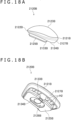
- FIG. 18A is a side view of the type-B second control button 2120B
- FIG. 18B is a perspective view depicting the lower side of the type-B second control button 2120B
- FIG. 19A is a side view of the type-C second control button 2120C
- FIG. 19B is a perspective view depicting the lower side of the type-C second control button 2120C
- FIG. 20 is a perspective view depicting the lower side of the type-D second control button 2120D.
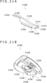
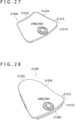
- FIG. 21A is a side view of the type-E second control button 2120E
- FIG. 21B is a perspective view depicting the lower side of the type-E second control button 2120E
- FIG. 21C is an exploded perspective view of the type-E second control button 2120E, and depicts the lower side of the type-E second control button 2120E.
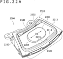
- FIG. 22A is a perspective view of a switch unit 2300 that is arranged around the first control button 2110 on the body 2100, and is provided with a button receiving portion 2301.
- FIG. 22B is an exploded perspective view depicting constituent elements of the switch unit 2300.
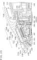
- FIG. 23 is a cross-sectional view taken along a line A-A in FIG. 15
- FIG. 24 is a cross-sectional view taken along a line B-B in FIG. 15 .
- FIG. 23 and FIG. 24 depict states where the type-A second control button 2120A is attached to the button receiving portion 2301.
- FIG. 25 is a cross-sectional view taken along a line C-C in FIG. 15 , and depicts a state where the type-E second control button 2120E is attached to the button receiving portion 2301.
- a top surface portion 2123A of the type-A second control button 2120A includes an outer circumferential edge 2121A and an inner circumferential edge 2122A of the second control button 2120A, and faces upward and a diagonal direction relative to the radial direction of the body 2100 (a direction from the inner circumferential edge 2122A toward the outer circumferential edge 2121A).
- the top surface portion 2123A of the type-A second control button 2120A is slightly curved in the upward/downward direction.
- the bottom surface portion 2124A of the type-A second control button 2120A includes the outer circumferential edge 2121A and the inner circumferential edge 2122A similarly to the top surface portion 2023A.
- the bottom surface portion 2124A of the type-A second control button 2120A faces downward and a diagonal direction relative to the radial direction of the body 2100 (a direction from the outer circumferential edge 2121A toward the inner circumferential edge 2122A).
- the thickness of the outer circumferential edge 2121A is greater than the thickness of the inner circumferential edge 2122A.
- the type-A second control button 2120A has an inclined surface 2127A on the outer circumferential edge 2121A.
- the inclined surface 2127A is the bottom surface of the outer circumferential portion 2131 of the second control button 2120A, and is inclined downward and inward.
- the type-A second control button 2120A has a fitting projection portion 2125A at the bottom surface portion 2124A.
- the fitting projection portion 2125A has a shape corresponding to the plurality of button receiving portions 2301 (see FIG. 16 ) provided at the top surface portion 2101 of the body 2100.
- the fitting projection portion 2125A can be attached to any of the plurality of button receiving portions 2301.
- the fitting projection portion 2125A protrudes downward from the bottom surface portion 2124A.
- the plurality of button receiving portions 2301 are recess downward from the top surface portion 2101 of the body 2100, and have fitting recess portions 2302 (see FIG. 22A ) that receive the fitting projection portion 2125A of the second control button 2120A.
- a relation between the recess and projection of the fitting projection portion 2125A and the button receiving portions 2301 may be opposite.
- the fitting projection portion 2125A of the second control button 2120A has, at its central portion, a first fitting portion 2126A (see FIG. 17B ), and a button receiving portion 2301 has, at its central portion (a central portion of the fitting recess portion 2302), a second fitting portion 2303 (see FIG. 22A ).
- the second fitting portion 2303 of the button receiving portion 2301 fits inside the first fitting portion 2126A of the second control button 2125A.
- first fitting portions 2126B to 2126E to which the second fitting portions 2303 of the button receiving portions 2301 fit are formed also at central portions of fitting projection portions 2125B to 2125E of the type-B to type-E second control buttons 2120B to 2120E mentioned later.
- first fitting portion 2126A is a recess portion which is recess in a direction away from the button receiving portion 2301
- second fitting portion 2303 is a projection portion protruding toward the second control button 2120A in FIG. 17B and FIG. 22A
- the relation between the recess and projection of the first fitting portion 2126A and the second fitting portion 2303 may be opposite.
- first fitting portion 2126A may be a projection portion protruding toward the button receiving portion 2301
- second fitting portion 2303 may be a recess portion which is recess in a direction away from the second control button 2120A
- first fitting portion 2126A and the second fitting portion 2303 have oblong shapes having corner portions that are rounded in a plan view
- the shapes of the first fitting portion 2126A and the second fitting portion 2303 are not limited to these.
- a top surface portion 2123B and a bottom surface portion 2124B of the type-B second control button 2120B include an outer circumferential edge 2121B and an inner circumferential edge 2122B.
- the type-B second control button 2120B has an inclined surface 2127B on the outer circumferential edge 2121B.
- the inclined surface 2127B is the bottom surface of the outer circumferential portion 2131 of the second control button 2120B, and is inclined downward and inward.
- the top surface portion 2123B of the type-B second control button 2120B bulges upward at its central portion unlike the top surface portion 2123A of the type-A second control button 2120A.
- the top surface portion 2123B of the type-B second control button 2120B has a bulging shape, it is easier for some users to control the type-B second control button 2120B as compared with the type-A second control button 2120A, in some cases.
- the user controls the second control button 2120B by sliding the hand along the top surface portion of the dome-like first control button 2110, in some cases. Since the hand of the user interferes with the top surface portion 2123B of the second control button 2120B in that process, press-control of the type-B second control button 2120B becomes easier as compared to control of the type-A second control button 2120A in some cases.
- the fitting projection portion 2125B similar to the fitting projection portion 2125A of the type-A second control button 2120A is formed also at the bottom surface portion 2124B of the type-B second control button 2120B.
- the type-B second control button 2120B also can be attached, at the fitting projection portion 2125B, to any of the plurality of button receiving portions 2301.
- a plurality of holes H2 are formed through the bottom surface portion 2124B of the type-B second control button 2120B, and it is attempted thereby to reduce the weight of the type-B second control button 2120B.
- a top surface portion 2123C and a bottom surface portion 2124C of the type-C second control button 2120C include an outer circumferential edge 2121C and an inner circumferential edge 2122C.
- the type-C second control button 2120C has an inclined surface 2127C on the outer circumferential edge 2121C.
- the inclined surface 2127C is the bottom surface of the outer circumferential portion 2131 of the second control button 2120C, and is inclined downward and inward.
- the top surface portion 2123C of the type-C second control button 2120C faces upward and a diagonal direction relative to the radial direction of the body 2100 (a direction from the outer circumferential edge 2121C toward the inner circumferential edge 2122C), unlike the top surface portion 2123A of the type-A second control button 2120A.
- the top surface portion 2123C of the type-C second control button 2120C is slightly curved in the upward/downward direction.
- the bottom surface portion 2124C of the type-C second control button 2120A faces downward and a diagonal direction relative to a direction from the outer circumferential edge 2121C toward the inner circumferential edge 2122C, similarly to the bottom surface portion 2124A of the type-A second control button 2120A.
- the thickness of the type-C second control button 2120A in the upward/downward direction increases gradually from the inner circumferential edge 2122 toward the outer circumferential edge 2121.
- the position of the outer circumferential edge 2121C of the type-C second control button is the highest.
- the hand of the user interferes with the outer circumferential portion 2121C of the second control button 2120C.
- press-control of the type-C second control button 2120C is easier as compared to control of other second control buttons 2120 (e.g. the type-A second control button 2120A), in some cases.
- a fitting projection portion 2125C similar to the fitting projection portion 2125A of the type-A second control button 2120A is formed also at the bottom surface portion 2124C of the type-C second control button 2120C.
- the type-C second control button 2120C also can be attached, at the fitting projection portion 2125B, to any of the plurality of button receiving portions 2301.
- a plurality of holes H3 are formed through the bottom surface portion 2124C of the type-C second control button 2120C. Thereby, it is attempted to reduce the weight of the type-C second control button 2120C similarly to the type-B second control button 2120B.
- the type-D second control button 2120D is explained. As depicted in FIG. 14 and FIG. 20 , similarly to the type-A second control button 2120A, the type-D second control button 2120D has a top surface portion that faces upward and a diagonal direction relative to the radial direction of the body 2100 (a direction from an inner circumferential edge 2122D toward an outer circumferential edge 2121D), and is slightly curved in the upward/downward direction.
- the type-D second control button 2120D has an inclined surface 2127D on the outer circumferential edge 2121D.
- the inclined surface 2127D is the bottom surface of the outer circumferential portion 2131 of the second control button 2120D, and is inclined downward and inward.
- the type-D second control button 2120D is different from the type-A second control button 2120A in that the type-D second control button 2120D is wider than the type-A second control button 2120A in the circumferential direction of the body 2100 to which the plurality of second control buttons 2120 are attached.
- the type-D second control button 2120D becomes easier to press than the type-A second control button 2120A is, in some cases. In addition, it becomes easier to perform control of pressing adjacent buttons simultaneously, in some cases.
- the widths of the outer circumferential edges 2121A to 2121C in the circumferential direction are the same or approximately the same, and the width of the outer circumferential edge 2121D is or approximately is twice as large as the width of the outer circumferential edge 2121A.
- the widths of the inner circumferential edges 2122A to 2122C in the circumferential direction are the same or approximately the same, and the width of the inner circumferential edge 2122D is or approximately is twice as large as the width of the inner circumferential edge 2122A.
- two fitting projection portions 2125D similar to the fitting projection portion 2125A of the type-A second control button 2120A are formed also at the bottom surface portion 2124D of the type-D second control button 2120D.
- the type-D second control button 2120D is different from the type-A second control button 2120A also in that the number of the fitting projection portions 2125D is two.
- the two fitting projection portions 2125D are separate from each other in the circumferential direction of the body 2100 at the bottom surface portion 2124D of the type-D second control button 2120D.
- the type-D second control button 2120D is attached to the body 2100 by attaching the two fitting projection portions 2125D to two adjacent button receiving portions 2301 (see FIG. 16 ). By pressing the type-D second control button 2120D, a user can press one or both of switch elements 2381 (see FIG. 22B ) provided to the two adjacent button receiving portions 2301.
- the type-E second control button 2120E is explained. As depicted in FIG. 21A , similarly to the type-A second control button 2120A, the type-E second control button 2120E has the top surface portion 2123E that faces upward and a diagonal direction relative to the radial direction of the body 2100 (a direction from the inner circumferential edge 2122E toward an outer circumferential edge 2121E), and is slightly curved in the upward/downward direction. As depicted in FIG. 15 , the inner circumferential edge 2122E included in the top surface portion 2123E of the type-E second control button 2120E protrudes toward the central portion of the body 2100 more significantly than the inner circumferential edges 2122 of the other second control buttons 2120 do.
- the overhanging portion 2132E including the inner circumferential edge 2122E is formed at the top surface portion 2123E of the type-E second control button 2120E.
- the overhanging portion 2132E of the second control button 2120E covers a portion of the top surface portion of the first control button 2110.
- a fitting projection portion 2125E is formed also at a bottom surface portion 2124E of the type-E second control button 2120E.
- the fitting projection portions 2125A and 2125E of the second control buttons 2120A and 2120E have, on the sides of the inner circumferential edges 2122A and 2122E, engagement portions 2151 (second engagement portions) that engage with button receiving portions 2301.
- engagement portions 2151 that engage with button receiving portions 2301 are formed also at the fitting projection portions 2125B to 2125C of the type-B to type-D second control buttons 2120B to 2120C.
- the fitting projection portion 2125E of the type-E second control button 2120E has, also on the side of the outer circumferential edge 2121E, an engagement portion 2128E (first engagement portion) that engages with the button receiving portion 2301.
- the outer circumferential edge 2121E of the type-E second control button 2120E is provided with a movable portion 2129E that protrudes outward from the second control button 2120E, and can be pressed in the direction toward the inner circumferential edge 2122E.
- the engagement portion 2128E moves in the direction toward the inner circumferential edge 2122E according to press-control of the movable portion 2129E.
- the engagement portion 2128E and the movable portion 2129E are provided only to the type-E second control button 2120E.
- engagement portions to be caught by button receiving portions 2301 are not formed on the outer-circumferential-edge-2121 sides of the fitting projection portions 2125A to 2125D.
- the type-A to type-D second control buttons 2120A to 2120D are not provided with movable portions that can be pressed in the directions toward the inner circumferential edges 2122.
- the type-E second control button 2120E has an upper member 2140E on which the outer circumferential edge 2121E, the inner circumferential edge 2122E, the top surface portion 2123E (see FIG. 21A ), and the bottom surface portion 2124E of the type-E second control button 2120E are formed, and a lower member 2150E on which the fitting projection portion 2125E is formed.
- the type-E second control button 2120E is formed by combining the upper member 2140E and the lower member 2150E in the upward/downward direction.
- each of the type-A to type-D second control buttons 2120A to 2120D also may be formed by combining an upper member (e.g. an upper member 2140A depicted in FIG. 23 ), and a lower member (e.g. a lower member 2150A depicted in FIG. 23 ).
- a side surface 2141E closer to the inner circumferential edge 2122E of the upper member 2140E of the type-E second control button 2120E is recess in an arc-like shape along the outer circumferential edge C2 of the first control button 2110.
- the type-E second control button 2120E has an engagement member 2160E on which the engagement portion 2128E and the movable portion 2129E are formed.
- the engagement member 2160E is arranged between the upper member 2140E and the lower member 2150E.
- a housing recess portion 2142E which is recess upward relative to the bottom surface portion 2124E is formed on the upper member 2140E, and the engagement member 2160E is housed inside the housing recess portion 2142E.
- the type-A to type-D second control buttons 2120A to 2120D do not have members equivalent to the engagement member 2160E.
- the engagement member 2160E has a base portion 2161E on which the engagement portion 2128E and the movable portion 2129E are formed, a fixation portion 2162E that is separate from the base portion 2161E in the direction toward the inner circumferential edge 2122E, a spring portion 2163E that extends curvedly from the base portion 2161E, and is continuous to the fixation portion 2162E, and a stopper portion 2164E extending from the base portion 2161E in the direction toward the inner circumferential edge 2122E.
- the engagement portion 2128E is a claw portion extending downward from the base portion 2161E, and having a lower end protruding in the direction toward the movable portion 2129E.
- the fixation portion 2162E of the engagement member 2160E is fixed to the housing recess portion 2142E of the upper member 2140E. Thereby, the fixation portion 2162E is fixed at a position relative to the upper member 2140E and the lower member 2150E.
- the fixation portion 2162E is fixed at a position relative to the upper member 2140E and the lower member 2150E.
- the base portion 2161E and the engagement portion 2128E formed on the base portion 2161E move in a direction to approach the fixation portion 2162E due to elastic warping of the spring portion 2163E.
- the stopper portion 2164E restricts excessive pressing of the movable portion 2129E.
- the base portion 2161E and the engagement portion 2128E move in a direction away from the fixation portion 2162E, and returns to the initial position since the shape of the spring portion 2163E returns to the initial state.
- the movable portion 2129E and the engagement portion 2128E can move relative to a member 2131E and the lower member 2150E.
- buttons 2120A to 2120E can be attached on the body 2100.
- the body 2100 is provided with the plurality of button receiving portions 2301.
- Each button receiving portion 2301 is provided to a switch unit 2300 depicted in FIG. 22A and FIG. 22B .
- the plurality of button receiving portions 2301 and the plurality of switch units 2300 surround the first control button 2110.
- each switch unit 2300 has a base member 2310, a cover member 2320 that covers a portion of the base member 2310, a first support member 2330 that supports the base member 2310 from below, a shaft member 2340, a flat-plate-like magnet 2350, a magnetic material 2360 that covers the lower side of the magnet 2350, a second support member 2370 that supports the magnet 2350 and the magnetic material 2360 from below, and a second circuit board 2380 having a top surface portion on which a switch element 2381 is implemented.
- the cover member 2320 is formed in a frame-like shape and has an opening H4 at its central portion. A button receiving portion 2301 is exposed through the opening H4 of the cover member 2320.
- An engagement portion 2321 to be caught by the first support member 2330 is formed at the lower end of the cover member 2320.
- the base member 2310 and the shaft member 2340 are arranged between the cover member 2320 and the first support member 2330.
- the base member 2310 there is a recess portion on a side (lower side) opposite to the second fitting portion 2303 which is a projection top surface portion, and the magnet 2350 and the magnetic material 2360 are housed inside the recess portion.
- a wall portion 2313 surrounding the second fitting portion 2303 is formed at the top surface portion of the base member 2310.
- a projection portion 2316 protruding to the outer-circumferential-edge-C1 side of the body 2100 is formed outside the wall portion 2313.
- the projection portion 2316 of the base member 2310 is sandwiched between the cover member 2320 and the first support member 2330 in the upward/downward direction. Thereby, it is possible to prevent the base member 2310 from being detached on the outer-circumferential-edge-C1 side of the body 2100.
- the shaft member 2340 is provided to the base member 2310.
- the shaft member 2340 is attached to the base member 2310 and can rotate about an axis Ax1 relative to the base member 2310.
- the shaft member 2340 has a shaft portion 2341 extending along the axis Ax1, and an engagement portion 2342 positioned above the axis Ax1.
- the engagement portion 2342 is a claw portion extending upward from the shaft portion 2341, and having an upper end portion protruding in the direction toward the outer circumferential edge C1 of the body 2100.
- the engagement portion 2342 extends along the axis Ax1. As depicted in FIG.
- the engagement portion 2342 surrounds the fitting recess portion 2302, and the second fitting portion 2303 provided to the fitting recess portion 2302.
- the engagement portion 2342 may be a recess portion to be caught by the engagement portion 2151 of the second control button 2120.
- the second circuit board 2380 of the switch unit 2300 depicted in FIG. 22B is fixed to the first support member 2330 by a fixing member 2390 such as a screw.
- An opening H5 is formed through a central portion of the first support member 2330, and the switch element 2381 is exposed through the opening H5.
- the second support member 2370, the magnetic material 2360, the magnet 2350, the base member 2310, and the cover member 2320 are arranged above the switch element 2381 in this order from below.
- the second support member 2370 moves downward via the base member 2310 and the magnet 2350.
- the switch element 2381 senses that the second control button 2120 is pressed by the user.
- the type-A second control button 2120A is formed by combining, in the upward/downward direction, the upper member 2140A on which the outer circumferential edge 2121A, the top surface portion 2123A, and the like are formed, and the lower member 2150A on which the fitting projection portion 2125A is formed.
- the top surface portion 2123A of the type-A second control button 2120A is arranged above an extended line L1 along the top surface portion of the first control button 2110.
- the top surface portions 2123B to 2123E of the type-B to type-E second control buttons 2120B to 2120E also are arranged above the extended line along the top surface portion of the first control button 2110.
- the controller 2000 has a first magnetic structure and a second magnetic structure.
- the first magnetic structure includes at least two magnetic poles that are separated in the circumferential direction of the body 2100 (first direction).
- the second magnetic structure includes a magnetic material or a magnet facing the at least two magnetic poles of the first magnetic structure.
- magnetic poles mean end surfaces such as end portions of a magnet or end portions of a magnetic material where magnetic fluxes exit and enter.
- the first magnetic structure is provided to one of the base member 2310 included in a button receiving portion 2301 and a second control button 2120, and the second magnetic structure is provided to the other one of the base member 2310 and the second control button 2120.
- the second control button 2120 is attracted to the button receiving portion 2301 by magnetic force.
- the posture of the second control button 2120 can be corrected by the magnetic force.
- a user only has to arrange the second control button 2120 at an approximate position when attaching the second control button 2120 to the button receiving portion 2301, and attachment work of the second control button 2120 can be performed easily. For example, it becomes possible for a user to attach the second control button 2120 to the button receiving portion 2301 by causing the second control button 2120 to slide along the top surface portion of the dome-like first control button 2110, and moving the second control button 2120.
- the base member 2310 has the one magnet 2350
- the second control button 2120 has one magnetic material 2152.
- the magnet 2350 has a magnetic pole (e.g. N pole) N1 on the upper side, and has a magnetic pole (a magnetic pole opposite to the magnetic pole N1, for example S pole) S1 on the lower side.
- the magnetic pole N1 and the magnetic pole S1 of the magnet 2350 are separated in the upward/downward direction (the press-down direction of the second control button 2120, and a third direction crossing the first direction and a second direction mentioned later).
- the magnetic material 2152 is a sheet metal, is fixed to the lower member 2150A, and is exposed downward through the first fitting portion 2126A ( FIG. 17B ) which is a recess portion or the like.
- the type-B to type-E second control buttons 2120B to 2120E also have magnetic materials 2152 fixed to the lower members.
- the magnetic material 2152 faces the magnet 2350 provided on the lower side of the button receiving portion 2301, and is attracted to the button receiving portion 2301 by magnetic force of the magnet 2350.
- the base member 2310 may have a magnetic material
- the second control button 2120 may have a magnet.
- the second control button 2120 may have a magnet instead of having the magnetic material 2152.
- the first magnetic structure includes the U-shaped magnetic material 2360.
- the magnet 2350 is arranged in a recess portion of the U-shaped magnetic material 2360.
- the magnetic material 2360 functions as a generally-called magnetization yoke that enhances the force of the magnet 2350 to the attract magnetic material 2152.
- magnetic force of magnetic poles e.g. S poles
- S2 and S3 opposite to a magnetic pole (e.g. N pole) N1 on the upper side of the magnet 2350 is generated by the magnet 2350.
- N pole e.g. N pole
- a relation between the N pole and the S pole of the magnet 2350 and the magnetic material 2360 may be opposite.
- the three magnetic poles S2, N1, and S3 including the magnetic pole N1 of the magnet 2350 are arrayed in the button receiving portion 2301 in this order along the circumferential direction of the body 2100 (a direction represented by an arrow D3 in FIG. 22A and FIG. 24 ).
- the length of the button receiving portion 2301 in the circumferential direction of the body 2100 is greater than the length of the button receiving portion 2301 in the radial direction of the body 2100.
- the magnetic poles S2, N1, and S3 included in the first magnetic structure are arrayed along the longitudinal direction of the button receiving portion 2301.
- the posture of the second control button 2120 relative to the button receiving portion 2301 can be corrected by magnetic force. Thereby, the work to attach the second control button 2120 to the button receiving portion 2301 becomes easier.
- the number of magnets 2350 arranged in the button receiving portion 2301 can be reduced.
- the first magnetic structure may have a plurality of magnets.
- the plurality of magnets are separated in the circumferential direction of the body 2100 (first direction).
- magnetic poles of two adjacent magnets in the plurality of magnets are preferably opposite magnetic poles.
- the magnetic pole on the upper side of one magnet is the N pole
- the magnetic pole on the upper side of a magnet adjacent thereto is preferably the S pole.
- the first magnetic structure may have a plurality of U-shaped magnetic materials.
- magnets in the plurality of magnets may be arranged respective recess portions of the plurality of U-shaped magnetic materials.
- the button receiving portion 2301 of the body 2100 includes the base member 2310, and the shaft member 2340 attached to the base member 2310, and the shaft member 2340 extends along the axis Ax1, and has the shaft portion 2341 including the axis Ax1, and the engagement portion 2342 extending upward from the shaft portion 2341.
- the engagement portion 2342 of the shaft member 2340 is arranged between the first control button 2110 and the second control button 2120A, and is in contact with the second control button 2120A.
- the fitting projection portion 2125A of the second control button 2120A has the engagement portion 2151 at a position on the inner-circumferential-edge-2122 side.
- the engagement portion 2151 of the second control button 2120A is in contact with the engagement portion 2342 of the shaft member 2340, and is engaged with the engagement portion 2342.
- the engagement portion 2151 which is a claw portion, is caught by the engagement portion 2342, which is a claw portion as well.
- One of the engagement portion 2151 and the engagement portion 2342 may be a claw portion, and the other may be a recess portion to be caught by the claw.
- engagement portions to engage with engagement portions 2342 of shaft members 2340 are formed also at the fitting projection portions 2125B to 2125D of the type-B to type-D second control buttons 2120B to 2120D.
- the engagement portion 2151 of the second control button 2120A is positioned in a direction (the second direction, a direction crossing the first direction in which the at least two magnetic poles are separated) toward the central portion of the body 2100 relative to the at least two magnetic poles included in the first magnetic structure (e.g. the three magnetic poles formed by the magnet 2350 and the U-shaped magnetic material 2360).
- the second control button 2120A can be pressed down in the third direction crossing the first direction and the second direction.
- the engagement portion 2151 of the second control button 2120A is separated in the second direction (a direction crossing the first direction in which the at least two magnetic poles are separated, and the third direction which is the press-down direction of the second control button 2120A) relative to the magnetic poles of the first magnetic structure, it is possible to prevent the second control button from being detached from the body 2100 when a side opposite to the side where the engagement portion 2151 is provided to the second control button 2120A is pressed down.
- the second control button 2120A extends beyond the outer circumferential edge of the button receiving portion 2301 in a direction (a direction toward the outer circumferential edge C1 of the body 2100) opposite to the direction in which the engagement portion 2151 is positioned relative to the at least two magnetic poles included in the first magnetic structure.
- the second control button 2120A covers the entire button receiving portion 2301.
- the second control button 2120A has a first portion A1 and a second portion A2.
- the first portion A1 is positioned on a side where the engagement portion 2151 is provided, relative to the at least two magnetic poles of the first magnetic mechanism.
- the second portion A2 is a portion on a side opposite to the first portion A1, relative to the at least two magnetic poles of the first magnetic mechanism.
- the width of the second portion A2 in the radial direction of the body 2100 (second direction) is greater than the width of the first portion A1.
- the second portion A2 is larger than the first portion A1. Because of this, it is easier for a user to press the second portion A2 than the first portion A1.
- a clearance D1 is formed between the outer circumferential portion C1 of the body 2100 and the second control button 2120A. Because of this, in a case where a user presses down a position (e.g. the second portion A2) closer to the outer circumferential edge 2121A of the second control button 2120A, a portion (e.g. the first portion A1) closer to the inner circumferential edge 2122A of the second control button 2120A is urged upward. Here, at the portion closer to the inner circumferential edge 2122A of the second control button 2120A, the engagement portion 2151 is caught by the engagement portion 2342 of the button receiving portion 2301.
- the widths, in the radial direction of the body 2100, of second portions which are on sides opposite to first portions on the sides where the engagement portions 2151 are provided are greater than the widths of the first portions.
- the engagement portion 2342 of the shaft member 2340 is urged to a position depicted in FIG. 23 (hereinafter, referred to as a lock position) by an elastic member (not depicted) such as a spring.
- an elastic member such as a spring.
- the engagement portion 2342 is arranged at the lock position, and is engaged with the engagement portion 2151 of the second control button 2120A.
- the engagement portion 2342 of the shaft member 2340 is pressed by the second control button 2120A, and the entire shaft member 2340 rotates about the axis Ax1.
- the engagement portion 2342 of the shaft member 2340 moves from the lock position, which is the initial position depicted in FIG. 23 , to an unlock position (a position closer to the first control button 2110 than the lock position is).
- an unlock position a position closer to the first control button 2110 than the lock position is.
- the inclined surface 2127A extending downward and in the direction toward the central portion of the body 2100 from the outer edge of the outer circumferential edge 2121A of the type-A second control button 2120A is formed at the outer circumferential edge 2121A.
- the button receiving portion 2301 including the base member 2310 and the shaft member 2340 is urged upward by the switch of the switch element 2381.
- An outer edge portion of the button receiving portion 2301 abuts on the frame-like cover member 2320 where the opening H4 (see FIG. 22B ) is formed.
- the projection portion 2316 (see FIG.
- the base member 2310 is arranged on one side (an end portion closer to the edge portion C1 of the body 2100) of the outer edge portion of the button receiving portion 2301, and a projection portion 2343 protruding in a direction toward the central portion of the body 2100 (a direction crossing the upward/downward direction and the axis Ax1) from the shaft portion 2341 of the shaft member 2340 is arranged on the other side (an end portion closer to the central portion of the body 2100) of the outer edge portion.
- the projection portion 2316 of the base member 2310 and the projection portion 2343 of the shaft member 2340 abut on the cover member 2320 fixed to the body 2100.
- the button receiving portion 2301 can move downward with a side opposite to the pressed side as a fulcrum. Thereby, it becomes possible to control the switch of the switch element 2381 by pressing either of both the one side and the other side of the outer edge portion of the button receiving portion 2301.
- the type-E second control button 2120E is formed by combining the upper member 2140E and the lower member 2150E in the upward/downward direction, and the engagement member 2160E is arranged between the upper member 2140E and the lower member 2150E.
- the type-E second control button 2120E also has the magnetic material 2152 such as a sheet metal on the lower member 2150E. Thereby, the magnetic material 2152 is attracted to the button receiving portion 2301 by magnetic force of the magnet 2350 provided to the button receiving portion 2301, and it is possible to make it easier to attach the type-E second control button 2120E to the button receiving portion 2301.
- the posture of the type-E second control button 2120E can be corrected when the type-E second control button 2120E is attached to the button receiving portion 2301.
- the overhanging portion 2132E including the inner circumferential edge 2122E of the type-E second control button 2120E covers a portion including the outer circumferential edge C2 of the top surface portion of the first control button 2110. It is ensured that a clearance D2 is formed in the upward/downward direction between the overhanging portion 2132E and the top surface portion of the first control button 2110.
- the clearance D2 is larger than the movable range of the second control button 2120E (i.e. the movable range of the button receiving portion 2301). Thereby, the overhanging portion 2132E is prevented from interfering with the first control button 2110 when the type-E second control button 2120E is pressed down.
- the type-E second control button 2120E includes the outer circumferential portion 2131E extending outward beyond the outer circumferential edge C1 of the body 2100.
- the type-A to type-D second control buttons 2120A to 2120D also include the outer circumferential portions 2131 (e.g. the outer circumferential portion 2313A of the type-A second control button 2120A depicted in FIG. 23 ) extending outward beyond the outer circumferential edge C1.
- the width of the overhanging portion 2132E is narrower than the width of the outer circumferential portion 2131E.
- the layout of a plurality of control buttons including the type-E second control button 2120E on the body 2100 becomes easier.
- the fitting projection portion 2125E of the type-E second control button 2120E similarly to the type-A second control button 2120A, has the engagement portion 2151 (second engagement portion) at a position closer to the inner circumferential edge 2122E of the fitting projection portion 2125E (a position closer to the overhanging portion 2132E).
- the engagement portion 2151 is engaged with the engagement portion 2342 of the shaft member 2340.
- the type-E second control button 2120E has the engagement portion 2128E (first engagement portion) at a position closer to the outer circumferential edge 2121E of the type-E second control button 2120E.
- the engagement portion 2128E is provided at a position closer to a side opposite to the overhanging portion 2132E.
- the base member 2310 included in the button receiving portion 2301 has an engagement portion 2315.
- the engagement portion 2315 of the button receiving portion 2301 is formed under the wall portion 2313 (see FIG. 22B ). In a state where the second control button 2120E is attached to the button receiving portion 2301, the engagement portion 2128E of the second control button 2120E is caught by the engagement portion 2315 of the base member 2310.
- the engagement portion 2128E is caught by the button receiving portion 2301 at a position closer to the outer circumferential portion 2131E. Because of this, it is possible to effectively prevent the type-E second control button 2120E from being detached from the button receiving portion 2301 even in a case where a user presses downward the overhanging portion 2132E protruding significantly from the first control button 2110, and the outer circumferential portion 2131E on the opposite side is urged upward.
- the outer circumferential portion 2131E of the second control button 2120E is provided with the movable portion 2129E.
- the engagement portion 2128E of the second control button 2120E moves from a lock position, which is the initial position depicted in FIG. 25 , to an unlock position (a position closer to the inner circumferential edge 2122 than the lock position is).
- the user can disengage the engagement portion 2128E of the second control button 2120E and the engagement portion 2315 of the base member 2310 by pressing the movable portion 2129E.
- an inclined surface 2135E extending downward and in the direction toward the central portion of the body 2100 from the outer edge of the outer surface of the movable portion 2129E provided to the outer circumferential edge 2121A of the type-E second control button 2120A is formed on the outer surface.
- the second control button 2120E moves upward and in a diagonal direction toward the middle portion of the body 2100. Due to the movement of the second control button 2120E toward the middle portion of the body 2100, the second control button 2120E can press the engagement portion 2342 of the shaft member 2340, and it becomes possible to remove the second control button 2120E from the button receiving portion 2301.
- the type-A second control button 2120A is not provided with an engagement portion to engage with the engagement portion 2315 of the base member 2310.
- a guided slope 2133A to be guided by the wall portion 2313 (see FIG. 22A and FIG. 22B ) of the base member 2310 is formed on the outer circumferential surface of a fitting projection portion 2125.
- the guided slope 2133A is inclined from an outer edge (an outer edge closer to the outer circumferential edge 2121A) of the fitting projection portion 2125A downward and in a direction toward the inner circumferential edge 2122A.
- a guide slope 2314 extending downward and in a direction toward the second fitting portion 2303 is formed inside the wall portion 2313 surrounding the second fitting portion 2303 at the top surface portion of the base member 2310. Since the guided slope 2133A formed at the fitting projection portion 2125A of the second control button 2120A abuts on the guide slope 2314, and slides along the guide slope 2314, the fitting projection portion 2125A can be guided to the inside of the wall portion 2313. Thereby, it is possible to make it easier to attach the type-A second control button 2120A to the button receiving portion 2301.
- guided slopes 2133B to 2133E are formed also at the fitting projection portions 2125B to 2125E of the type-B to type-E second control buttons 2120B to 2120E. Thereby, it is possible to make it easier to attach the type-B to type-E second control buttons 2120A also to the button receiving portions 2301.
- the first fitting portion 2126A is formed at the central portion of the fitting projection portion 2125A.
- a wall surface 2134A is formed at the first fitting portion 2126A.
- the wall surface 2134A of the first fitting portion 2126A is a surface perpendicular to the bottom surface of the fitting projection portion 2125A.
- the wall surface 2134A of the first fitting portion 2126A may be a surface closer to a plane perpendicular to the bottom surface of the fitting projection portion 2125A than the guided slope 2133A is.
- the second fitting portion 2303 (second fitting portion) protruding upward is formed at the central portion of the button receiving portion 2301.
- a wall surface 2304 is formed also at the second fitting portion 2303.
- the wall surface 2304 of the second fitting portion 2303 is a surface perpendicular to the bottom surface of the button receiving portion 2301 (the bottom surface of the fitting recess portion 2302).
- the wall surface 2304 of the second fitting portion 2303 may be a surface closer to a plane perpendicular to the bottom surface of the button receiving portion 2301 than the guide slope 2314 is.
- the wall surface 2134A of the first fitting portion 2126A abuts on the wall surface 2304 of the second fitting portion 2303. Thereby, it is possible to prevent the second control button 2120A from moving along the bottom surface of the button receiving portion 2301 (the bottom surface of the fitting recess portion 2302).
- wall surfaces 2134B to 2134E are formed also at the recess portions 2126B to 2126E of the fitting projection portions 2125B to 2125E of the type-B to type-E second control buttons 2120B to 2120E. Thereby, it is possible to prevent also the type-B to type-E second control buttons 2120B to 2120E from moving along the bottom surfaces of the button receiving portions 2301.
- FIG. 26A is a perspective view of a mark member 2400 attached to a second control button 2120.
- FIG. 26B is a side view of the mark member 2400.
- the mark member 2400 may be manufactured by using, as a material, a resin, a rubber material, or the like.
- the openings H1 are formed through the top surface portions of the plurality of second control buttons 2120 (e.g. the top surface portion 2123A of the type-A second button 2120A).
- the mark member 2400 can be attached to and removed from the opening H1 of a second control button 2120.
- the mark member 2400 has a top portion 2401 representing a mark which is characters, numerals, symbols, or a string which is a combination of these.
- the mark member 2400 has a fitting projection portion 2403 that protrudes downward from the top portion 2401, and engages with the opening H1 of the second control button 2120.
- the top portion 2401 has a circular shape in the example depicted in FIG. 26A
- the shape of the top portion 2401 may be a rectangular shape such as a square shape, or may be another shape.
- a symbol "circle" is provided as identification information on the top portion 2401.
- the mark member 2400 can be attached to the inside of the opening H1 of the second control button 2120, and can be removed from the opening H1.
- the fitting projection portion 2403 of the mark member 2400 has a first extending portion 2403a and a second extending portion 2403b that extend downward with the same length, and have lower ends which are formed as flanges, and the clearance D2 in the widthwise direction of the mark member 2400 is formed between the first extending portion 2403a and the second extending portion 2403b. Due to warping of the first extending portion 2403a and the second extending portion 2403b in directions toward the clearance D2, the overall width of the fitting projection portion 2403 narrows. Thereby, a user can put in the fitting projection portion 2403 inside the opening H1 formed through the top surface portion of the second control button 2120, and can pull out the fitting projection portion 2403 from the opening H1.
- FIG. 27 is a perspective view depicting the type-A second control button 2120A having a mark member 2400 is attached thereto.
- FIG. 28 is a perspective view depicting the type-E second control button 2120E having a mark member 2400 attached thereto.
- the opening H1 is formed at a position closer to an edge portion of the top surface portion of the second control button 2120 than to the central portion of the top surface portion. Because of this, as depicted in FIG. 27 and FIG. 28 , a mark member 2400 can be attached to and detached from a position closer to the edge portion of the top surface portion of the second control button 2120 than to the central portion of the top surface portion. With this configuration, it becomes easier to press the central portion of the top surface portion of the second control button 2120.
- the second control button 2120 has an outer circumferential portion 2121 extending outward beyond the outer circumferential edge C1 of the body 2100. As depicted in FIG. 27 and FIG. 28 , at least a portion of the top portion 2401 of a mark member 2400 overlaps a portion of the outer circumferential portion 2121 of a second control button 2120.
- a user can sense that she/he is touching a portion near the outer circumferential edge 2121E of a second control button, she/he is touching the central portion of the second control button 2120 in the widthwise direction, and so on, by touching the mark member 2400 during control of the second control button 2120. Thereby, it becomes easier for the user to check that a finger or the like is placed at a certain home position.
- the top portion 2401 of a mark member 2400 is circular, and a portion of the outer circumferential edge of the top portion 2401 overlaps a portion of the outer circumferential edge 2121 of a second control button 2120.
- the top portion 2401 of the mark member 2400 may have a portion extending outward from the second control button 2120 beyond the outer circumferential edge 2121 of the second control button 2120.
- the outer edge of the top portion 2401 of the mark member 2400 may have a portion overlapping the inner circumferential edge 2122 of the second control button 2120. With this configuration also, it is possible to make it easier to remove the mark member 2400.
- the top portion 2401 of a mark member 2400 has a bottom surface portion 2402 facing the top surface portion of a second control button 2120 in a state where the mark member 2400 is attached to the second control button 2120.
- the top surface portion 2123A of the type-A second button 2120A depicted in FIG. 27 is slightly curved in the upward/downward direction.
- the top surface portion 2123E of the type-E second button 2120E depicted in FIG. 28 also is slightly curved in the upward/downward direction.
- the bottom surface portion 2402 of the mark member 2400 is flat in the upward/downward direction.
- the mark member 2400 depicted in FIG. 28 is different from the mark member 2400 depicted in FIG. 27 in which the symbol "circle” is provided at the top portion 2401, in that a symbol “square” is provided at the top portion 2401 of the mark member 2400 depicted in FIG. 28 .
- a user can attach mark members 2400 provided with desired identification information to the plurality of second control buttons 2120.
- the user can attach, to the second control buttons 2120, mark members 2400 provided with marks corresponding to functions set in an application (e.g. a game application) executed by an information processing apparatus such as a console or a server.
- an application e.g. a game application
- the user changes the arrangement of the plurality of second control buttons 2120, and changes assignment of the switches of button receiving portions 2301 corresponding to functions in an application, in some cases.
- the user changes the arrangement of the plurality of second control buttons 2120, and changes assignment of the switches of button receiving portions 2301 corresponding to functions in an application, in some cases.
- by changing mark members 2400 attached to the second control buttons 2120 it is possible to prevent differences from being generated between functions set in an application and functions represented by the marks of the mark members 2400.
Landscapes
- Engineering & Computer Science (AREA)
- Multimedia (AREA)
- Human Computer Interaction (AREA)
- General Engineering & Computer Science (AREA)
- Theoretical Computer Science (AREA)
- Physics & Mathematics (AREA)
- General Physics & Mathematics (AREA)
- Automation & Control Theory (AREA)
- Position Input By Displaying (AREA)
- User Interface Of Digital Computer (AREA)
- Input From Keyboards Or The Like (AREA)
Abstract
Description
- The present disclosure relates to an input device.
- PTL 1 described below discloses an input device used for control of a game console. Input devices used for applications such as games are used by users to input control signals to the applications.
-
- There are also some users who have difficulty in feeling comfortable controlling existing input devices.
- An object of the present disclosure is to provide a new input device that can make control comfortable for users who have difficulty in feeling comfortable controlling existing input devices.
- An input device according to the present disclosure includes a body, a first control button having a top surface portion for placing a hand and attached to the body, and a plurality of second control buttons arranged along an outer edge of the first control button and attached to the body. Outer circumferential portions of the plurality of second control buttons extend outward beyond an outer circumferential edge of the body. This can make control of the input device comfortable for users who have difficulty in feeling comfortable controlling existing input devices.
-
- [
FIG. 1 ]
FIG. 1 is a block diagram of a system example including an embodiment according to the present principles. - [
FIG. 2 ]
FIG. 2 is a diagram depicting a first exemplary environment in which the present principles can be used. - [
FIG. 3 ]
FIG. 3 is a diagram depicting a second exemplary environment in which the present principles can be used. - [
FIG. 4 ]
FIG. 4 is a top-surface-portion perspective view of a controller in a state where an analog stick unit is at the proximate position. - [
FIG. 5 ]
FIG. 5 is a bottom-surface perspective view of the controller in a state where the analog stick unit is at the proximate position, and depicts attachment examples in a state where attachments are disassembled from a base portion. - [
FIG. 6 ]
FIG. 6 is a top-surface-portion view of the controller in a state where the analog stick unit is at the proximate position. - [
FIG. 7 ]
FIG. 7 is an exploded top-surface-portion perspective view of the controller in a state where the analog stick unit is extended. - [
FIG. 8 ]
FIG. 8 is a sectional perspective view of the controller. - [
FIG. 9 ]
FIG. 9 is a view depicting a control button mechanically coupled to a pad in a base portion, and depicting details ofFIG. 8 . - [
FIG. 10 ]
FIG. 10 is a detail view ofFIG. 8 depicting a state where the control button is detached from the pad in the base portion. - [
FIG. 11 ]
FIG. 11 is a view depicting a button arrangement example. - [
FIG. 12 ]
FIG. 12 is a view depicting another alternative button layout example. - [
FIG. 13 ]
FIG. 13 is a view depicting an attachment in a case where the attachment is configured as a leg strap to connect the base portion and a user. - [
FIG. 14 ]
FIG. 14 is a perspective view of a controller according to another embodiment (second embodiment). - [
FIG. 15 ]
FIG. 15 is a plan view of the controller. - [
FIG. 16 ]
FIG. 16 is an exploded perspective view depicting a state where a plurality of second control buttons and a control stick are disassembled from the controller. - [
FIG. 17A ]
FIG. 17A is a side view of a type-A second control button. - [
FIG. 17B ]
FIG. 17B is a perspective view depicting a lower side of the type-A second control button. - [
FIG. 18A ]
FIG. 18A is a side view of a type-B second control button. - [
FIG. 18B ]
FIG. 18B is a perspective view depicting a lower side of the type-B second control button. - [
FIG. 19A ]
FIG. 19A is a side view of a type-C second control button. - [
FIG. 19B ]
FIG. 19B is a perspective view depicting a lower side of the type-C second control button. - [
FIG. 20 ]
FIG. 20 is a perspective view depicting a lower side of a type-D second control button. - [
FIG. 21A ]
FIG. 21A is a side view of a type-E second control button. - [
FIG. 21B ]
FIG. 21B is a perspective view depicting a lower side of the type-E second control button. - [
FIG. 21C ]
FIG. 21C is an exploded perspective view of the type-E second control button. - [
FIG. 22A ]
FIG. 22A is a perspective view of a switch unit. - [
FIG. 22B ]
FIG. 22B is an exploded perspective view depicting constituent elements of the switch unit. - [
FIG. 23 ]
FIG. 23 is a cross-sectional view taken along a line A-A inFIG. 15 . - [
FIG. 24 ]
FIG. 24 is a cross-sectional view taken along a line B-B inFIG. 15 . - [
FIG. 25 ]
FIG. 25 is a cross-sectional view taken along a line C-C inFIG. 15 . - [
FIG. 26A ]
FIG. 26A is a perspective view of an identification member. - [
FIG. 26B ]
FIG. 26B is a side view of the identification member. - [
FIG. 27 ]
FIG. 27 is a perspective view depicting the type-A second control button in a state where the identification member is attached thereto. - [
FIG. 28 ]
FIG. 28 is a perspective view depicting the type-E second control button in a state where the identification member is attached thereto. - The present disclosure typically relates to a computer eco-system including an aspect of consumer electronics (CE) device networks not limited to computer game networks. The system in the present specification can include server and client components that are connected via a network such that data is exchanged between the client and server components. The client components can include one or more pieces of computing equipment such as game consoles such as Sony PlayStation (registered trademark), game consoles of Microsoft (registered trademark), Nintendo (registered trademark), or the like; virtual reality (VR) headsets, augmented reality (AR) headsets, portable televisions (smart televisions, Internet-enabled televisions, etc.), or portable computers (mobile equipment such as laptop personal computers or tablet terminals, additional equipment mentioned later such as smartphones). These client terminals may operate in various operating environments. For example, within the client computers, for example, Linux (registered trademark) or Unix (registered trademark) operating systems or operating systems manufactured by Microsoft (registered trademark), Apple (registered trademark), or Google (registered trademark) can be adopted. These operating environments can be used for executing one or more browsing programs such as browsers provided by Microsoft (registered trademark), Google (registered trademark), or Mozilla (registered trademark) that make it possible to access Web sites hosted by Internet servers mentioned later. In addition, an operating environment according to the present principles can be used for executing one or more computer game programs.
- Servers and/or gateways can include one or more processors (those that are configured to allow the servers to receive and transmit data on networks such as the Internet). In addition, clients and servers can also be connected by a local intranet or a virtual private network. Servers and controllers can be embodied by game consoles such as Sony PlayStation (registered trademark), personal computers, or the like.
- Information exchange is performed between clients and servers via networks, in some cases. Because of this, servers and clients can include network infrastructures for reliability and security such as firewalls, load balancers, transitory storage devises, or proxies. One or more servers can form an apparatus that implements a method of providing safe communities like online social websites to network members.
- Processors include single-chip or multi-chip processors that can execute logic by various types of line such as address lines, data lines, or control lines, registers, and shift registers.
- Constituent elements included in an embodiment can be used in any appropriate combination also in other embodiments. For example, any of various constituent elements described in the present specification and/or drawn in figures can be combined with another embodiment, replaced, or excluded.
- As can be seen by referring to
FIG. 1 specifically, anillustrative system 10 is depicted. Thesystem 10 can include one or more of illustrative apparatuses that are mentioned above, and explained further below according to the principles of the present invention. A first illustrative apparatus included in thesystem 10 is a consumer electronics (CE) device such as an audio video device (AVD) 12 not limited to an Internet-enabled television with a television tuner (equivalently, a set top box that controls a television). Alternatively, theAVD 12 may be a computerized Internet-enabled device such as a smartphone, a tablet computer, a laptop computer, a head mounted display (HMD), a wearable computerized apparatus, a music player, a headphone, or a device that can be transplanted onto skin. Despite this, it will be understood that theAVD 12 is configured to be compliant with the principles of this document (e.g. communicate with another CE devise in order to be compliant with the principles of this document, execute logic described in this document, and execute any other functions and/or operations described in this document). - Accordingly, in order to realize such principles, the
AVD 12 can be established with some or all of constituent elements depicted inFIG. 1 . For example, theAVD 12 can include one or more displays 14. Thedisplays 14 may be implemented by high-definition or ultra-high-definition flat screens with definition equal to or higher than "4K," and may support touch control for receiving user input signals via touch control on the displays. TheAVD 12 can include one ormore speakers 16 for outputting sound, and at least one additional input devise 18. The input devise 18 is a sound receiver, a microphone, or the like for inputting audible commands to theAVD 12 for controlling theAVD 12. Theillustrative AVD 12 can also include one or more network interfaces 20. Under the control of one ormore processors 24, the network interfaces 20 perform communication via at least onenetwork 22 such as the Internet, a wide area network (WAN), or a local area network (LAN). Accordingly, although this is not the sole example, theinterface 20 may be a Wi-Fi transceiver which is an example of a wireless computer network interface, and, for example, may be a mesh network transceiver. It will be understood that theprocessors 24 controls theAVD 12, e.g. controls thedisplays 14 to present images thereon, and receives inputs from thedisplays 14, in order to be compliant with the principles of this document including other elements of theAVD 12 described in the present specification. Furthermore, it should be noted that the network interfaces 20 may be other appropriate interfaces such as a wired or wireless modem or router, a wireless telephone transceiver, or a Wi-Fi transceiver mentioned above. - In addition to what was mentioned before, the
AVD 12 can also include one or more input/output ports 26 such as a high-definition multi-media interface (HDMI (registered trademark)) port or a universal serial bus (USB) port for physical connection with other CE devises, and/or a headphone port for connecting a headphone to theAVD 12, and presenting sound from theAVD 12 to a user via the headphone. For example, the input/output ports 26 may be connected to an audio video content cable or satellite source 26a by wired or wirelessly. Accordingly, the source 26a may be a separate or integrated set top box or a satellite receiver. Alternatively, the source 26a may be a game console or a disc player on which content is stored. The source 26a in a case where it is implemented as a game console can include some or all of constituent elements mentioned later in relation to a CE devise 48. - The
AVD 12 may further include one ormore computer memories 28 such as a non-transitory signal disc-based or solid state storage. TheAVD 12 may be included in the chassis of the AVD as a standalone device, or may be embodied as a personal video recording device (PVR) or a video disc player inside or outside the chassis of the AVD for reproducing AV programs or as a removable memory medium or a server mentioned later. In addition, in several embodiments, theAVD 12 can receive geographical positional information from a satellite or a mobile phone base station, and provide the information to theprocessors 24, and/or theAVD 12 can include a mobile phone receiver, a GPS receiver, and/or a position or position receiver such as analtimeter 30 that are arranged in relation to theprocessors 24, and configured to decide altitudes, but this is not the sole example. In addition, thecomponents 30 can also decide the three-dimensional position and orientation of theAVD 12 by an inertial measurement unit (IMU) typically including a combination of an accelerometer, a gyroscope, and a magnetometer, or can also be implemented by an event-based sensor. - In several embodiments, the
AVD 12 can include one ormore cameras 32. Thecameras 32 are a digital camera such as an infrared camera or a web camera, an event-based sensor, and/or a camera that can be integrated into theAVD 12, and controlled by theprocessors 24, and collects photographs/images, and/or videos according to the principles of this document. In addition, theAVD 12 may include each of aBluetooth transceiver 34 and anotherNFC element 36 for communication with another apparatus that uses the Bluetooth (registered trademark) and/or near field communication (NFC) technologies. Examples of the NFC element include a radio frequency identification (RFID) element. - Furthermore, the
AVD 12 can include one or moreauxiliary sensors 38 that provide inputs to the processors 24 (e.g. a motion sensor such as an accelerometer, a gyroscope, a cyclometer, or a magnetic sensor, an infrared (IR) sensor, an optical sensor, a speed and/or cadence sensor, an event-based sensor, a gesture sensor (e.g. for sensing gesture commands)). TheAVD 12 may include an over-the-air (OTA)television broadcast port 40 for receiving OTA television broadcasts to provide inputs to theprocessors 24. It should be noted that, in addition to what was described above, theAVD 12 can include also an infrared (IR) transmitter, an IR receiver, and/or anIR transceiver 42 such as an IR data association (IRDA) device. A battery (not depicted) may be provided for supplying electric power to theAVD 12, and similarly may be a mobile environment power generating apparatus that can convert kinetic energy into electric power for charging a battery and/or supplying electric power to theAVD 12. In addition, a graphics processing unit (GPU) 44 and a field programmable gate array (FPGA) 46 may be included. One or moretactile sense generators 47 may be provided for generating tactile signals that can be sensed by a human holding or touching a device. - As can be seen by referring to
FIG. 1 , in addition to theAVD 12, thesystem 10 may include one or more other types of CE devise. For example, a first CE devise 48 may be a computer game console that can be used to send sounds and videos of a computer game to theAVD 12 via a command directly sent to theAVD 12 and/or via a server mentioned later, and a second CE devise 50 may include components similar to those of the first CE devise 48. In the example depicted in the figure, the second CE devise 50 may be configured as a computer game controller to be controlled by a player, or may be configured as an HMD to be worn by a player. It is understood that, whereas only the two CE devises are depicted in this example, fewer devices or more devices can be used. An apparatus in the present specification can implement some or all of constituent elements depicted about theAVD 12. Any constituent element depicted in the following figures may incorporate some or all of the constituent elements depicted about theAVD 12. - At least one
server 52 mentioned before includes at least oneserver processor 54, at least one tangible computer-readable storage medium 56 such as a disc-based or solid state storage, and at least onenetwork interface 58 that enables communication with another apparatus inFIG. 1 via thenetwork 22 under the control of theserver processor 54, and can make easier communication between the server and a client apparatus according to the principles of this document actually. It should be noted that thenetwork interface 58 may be, for example, a wired or wireless modem or router, a Wi-Fi transceiver, or another appropriate interface like a wireless telephone transceiver, for example. - Accordingly, in several embodiments, the
server 52 may be an Internet server or an entire server "firm," and can include and execute "cloud" functions such that devices of thesystem 10 can access a "cloud" environment via theserver 52 in an illustrative embodiment for a network game application, for example. Alternatively, theserver 52 may be realized by one or more game consoles or another computer in the same room as another apparatus depicted inFIG. 1 or near the room. - Constituent elements depicted in the following figures include some or all of constituent elements depicted in
FIG. 1 , in some cases. -
FIG. 2 depicts that acontroller 200 according to the principles of this document can be used for inputting control signals to acomputer simulation console 202 in order to control display on adisplay 204 of a computer simulation executed on theconsole 202. For example, thedisplay 204 may be a television, an HMD (Head Mounted Display), or another display. -
FIG. 3 is a diagram depicting that thecontroller 200 according to the present principles inputs a control signal to acomputer simulation server 300 that can be implemented by theserver 52 inFIG. 2 , for example, and a computer simulation is executed on theserver 300, and is streamed to thedisplay 204. The simulation may be directly streamed to thedisplay 204 by theserver 300, or may be streamed via thesimulation console 202 depicted inFIG. 2 . - Next, a detailed example of the
controller 200 depicted inFIG. 2 and FIG. 3 is explained with reference toFIG. 4 to FIG. 10 . Individual constituent elements of thecontroller 200 mentioned later may be formed of injection-molded plastics, inkjet-printed plastics including ones that can be manufactured by a manufacturer or an end user, composite materials, metals, plastics which are combinations of them, or the like. - In the example depicted in the figure, a
base portion 400 having a circular peripheral portion supports, at its top portion, a plurality of control buttons including a central control (CC)button 402. TheCC button 402 can operate to send signals to a computerized apparatus such as theserver 300 inFIG. 3 or thesimulation console 202 inFIG. 2 when the apparatus is communicating with the controller through a wire and/or wirelessly. TheCC button 402 in the non-limiting example depicted in the figure may have a circular, and gently projection top surface portion. The shape of theCC button 402 may be another shape. - In the illustrative embodiment, the
CC button 402 has two functions as a normal control button, and an armrest or a palm rest. Note that in a case where theCC button 402 is used as an armrest or a palm rest, theCC button 402 may have a lock mechanism for stopping upward/downward movement. - A circular light-emitting section 403 (see
FIG. 7 ) is arranged around the central button, and is devised such that the light-emitting section can be seen from any direction. One or more light emitting diodes (LEDs) or other light sources may be arranged under the transparent orsemi-transparent portion 403, and light to be propagated through theportion 403 may be provided. - A plurality of peripheral control (PC)
buttons 404 surround the circular light-emittingsection 403, and accordingly surround theCC button 402 as depicted in the figure. In the non-limiting example depicted in the figure, thePC buttons 404 completely surround theCC button 402 leaving only small spaces between theadjacent PC buttons 404. ThePC buttons 404 may have mutually different shapes, sizes, colors, and textures. Some of thePC buttons 404 may have identical colors and textures, when desired. Each PC button can operate to transmit signals to a computerized apparatus when the computerized apparatus is communicating with the apparatus. - As depicted in
FIG. 4 andFIG. 6 , one or more of thePC buttons 404 may have outer edge portions overhanging the base portion 400 (extending radially outward beyond the peripheral portion) in order to make it easier to replace the buttons with one finger or an elbow. Accordingly, end portions of the tops of the PC buttons may have shapes protruding from an end portion of thecontroller base portion 400. - In the non-limiting example depicted in the figure, a
first PC button 406 in a top view includes, when seen from above, a curved innercircumferential portion 408 closest to theCC button 402, andside surfaces 410 that spread outward, and are curved slightly or straight toward an outercircumferential portion 412. The outercircumferential portion 412 is larger (longer) than the innercircumferential portion 408. Thefirst PC button 406 has a flat top surface portion or a gently projection top surface portion, and may incline from the middle of the top surface portion in dimensions in both the radial direction (the dimension from the middle of the controller toward the outer edge of the controller) and the orientation direction. - In the non-limiting example depicted in the figure, there is a
second PC button 414 adjacent to thefirst PC button 406, and there is athird PC button 416 that is adjacent to thesecond PC button 414, and may have identical configuration and size as thesecond PC button 414. Unlike thefirst PC button 404, the second andthird PC buttons regions third PC buttons third PC buttons - It will be understood that the second and
third PC buttons regions - In the non-limiting example depicted in the figure, a
fourth PC button 424 is positioned next to thethird PC button 416, and may have the same configuration as the second andthird buttons outside region 426. - In the non-limiting example depicted in the figure, a
fifth PC button 428 is positioned next to thefourth PC button 424, and may have a contour that is flat or gently and continuously downwardly-inclined from a projection innercircumferential surface 430 of thefifth PC button 428 closest to the CC button to a projection outercircumferential surface 432. - In the non-limiting example depicted in the figure, a
sixth PC button 434 is positioned next to thefifth PC button 428, and may be configured with an identical shape as thefifth PC button 428, but may have a size larger than thefifth PC button 428. - In the non-limiting example depicted in the figure, a
seventh PC button 436 may be positioned between thesixth PC button 434 and thefirst PC button 406 as depicted in the figure, and may be larger than other PC buttons. As depicted inFIG. 6 , theseventh PC button 436 has a recess innercircumferential surface 438 in contrast to other PC buttons that may have projection inner circumferential surfaces, and theseventh PC button 436 may have straight side surfaces 440 that spread outward extending from the innercircumferential surface 438 to a projection outercircumferential surface 442. - One or more of the
PC buttons 404, all thePC button 404 in the example depicted in the figure, may be freely removably engaged with thebase portion 400. In a particular non-limiting example like the one depicted inFIG. 7 , eachPC button 404 can removably engage with eachpad 700 on thebase portion 400. The removable engagement may be friction or snap-fits between thePC buttons 404 and therespective pads 700, or the engagement may be magnetic engagement as depicted inFIG. 9 and FIG. 10 . Specifically, as depicted inFIG. 9 and FIG. 10 , each of thebuttons magnet 902 in eachpad 700 magnetically. It is understood that the magnets are positioned on the buttons, and the ferromagnetic plates are positioned on the pads of the base portion, in some cases. - Accordingly, button covers can be moved to different basic controls on the
base portion 400. In addition, functions of the controls themselves also can be defined by a user. - Each of the
buttons buttons fourth buttons - A top surface portion of each of the
buttons buttons fourth buttons
a dimpled texture, or another tactilely distinguishable texture. - Button shapes other than those described above also can be used. A plurality of buttons different from those described above also can be used. This recognition is part of the invention principles of this document, and does not constitute part of the technologies in the past.
-
FIGS. 4 to 7 are referred to again. In addition to a plurality of thecontrol buttons base portion 400, and can operate to send signals to a computerized apparatus when the computerized apparatus is communicating with the apparatus, an analog stick unit (ASU) 444 is included. TheASU 444 is engaged with thebase portion 400 such that acontrol portion 446 of theASU 444 can move between a proximate position (FIGS. 4 to 6 ) at which thecontrol portion 446 is arranged next to and in close proximity to thebase portion 400, and an extension position (FIG. 7 ) at which thecontrol portion 446 is apart from thebase portion 400. Furthermore, as explained in another location in the present specification, thecontrol portion 446 can rotate relative to thebase portion 400. In both the proximity configuration and the extension configuration, and in various angle directions, thecontrol portion 446 can be controlled in order to input control signals to a computerized apparatus. - The
control portion 446 may be a joystick-type input devise. The "north" of thecontrol portion 446 may be defined at the factory, or may be defined by a user. For example, the "north" may be defined such that a user's need is met most by using a user interface that permits the user to define which radial direction of theASU 444 should be defined as the "north." - An
additional control key 447 may be provided next to thecontrol portion 446 in theASU 444 as depicted in the figure for control for generating additional control signals for game play. - As depicted in
FIG. 5 , theASU 444 includes a flat-plate-like platform including aslide 448. Theslide 448 faces aparallel side surface 450 of thebase portion 400, and slidably engages with a receivingportion 452 of the base portion 400 (e.g. slidably engages with a flat-plate-like base-portion plate 454). It will be understood that the receivingportion 452 is on the bottom surface of thebase portion 400, and thecontrol buttons - In addition, the flat platform may include, at one end of the
slide 448, a disc-like support portion 456 to which thecontrol portion 446 is attached rotatably. In the example depicted in the figure, both thesupport portion 456 and thecontrol portion 446 are circular, and have substantially the same diameter. Thesupport portion 456 and theslide 448 may be formed of an integrated material such as a plastic. In addition, a separate structure combining an anti-slip rubber part and a plastic part can also be adopted. - The
control portion 446 can be controlled to generate signals to a computerized apparatus. In a non-limiting example, as best depicted inFIG. 7 , thecontrol portion 446 can include a point-and-click apparatus which is, in the example depicted in the figure, abutton 458 and abutton cover 460 to be pressed down to generate signals. As depicted in the figure, thebutton 458 is attached on arotatable ball 462 in around socket 464 that protrudes upward at the center of thecontrol portion 446. - The
button cover 460 has a relatively large size, and may have a strap hole for receiving a fastening strap or a carrying strap formed at its top portion. - Regarding electrical connectors associated with the
ASU 444, all connectors 466 (seeFIG. 4 ) not limited to a USB connector may be arranged on a side opposite to the analog stick unit in order to avoid interference of a cable in control of the analog stick by a user. Since a USB cable is the thickest in cables that are expected to be connected to the equipment and may influence the posture at the time of use, the USB connector may be arranged on a side 180 degrees opposite to the analog stick. - In addition, since a digital audio connector and an analog audio connector have the same visual appearances, they are arranged on both sides of the USB connector so as to make them distinguishable, in some cases. In several embodiments, a flexible buckle attachment 468 (see
FIG. 5 ) formed of a soft material such as silicon, rubber, or an elastic member can be attached to the rear surface of thebase portion 400. Since, due to its flexibility, the buckle attachment deforms along an attached portion such as a user's foot or arm, or an arm of a wheelchair, stable attachment is possible. - In the example depicted in the figure, as depicted in
FIG. 5 , twoscrew holes 470 may be formed through the bottom surface or another surface of thebase portion 400. Eachconnector 472 may pass through ahole 474 of theattachment 468, engage with ahole 470 of thebase portion 400, and hold the base portion and the attachment together. Another attachment like atripod 476 also can be engaged with thebase portion 400 similarly. -
FIG. 11 depicts an alternative button layout in which eightperipheral buttons 1100 surround around center button 1102. Theperipheral buttons 1100 may have identical shapes and sizes, and, in the example depicted in the figure, may have the shape of thefirst PC button 406 depicted inFIG. 4 . Note that in the present embodiment and other embodiments, buttons may be arranged left-right symmetrically along a circumferential edge portion of the base portion. -
FIG. 12 depicts an alternative button layout in whichperipheral buttons 1200 surround around center button 1202. Some or all of theperipheral buttons 1200 may have identical shapes such as circular shapes and identical sizes. In the example depicted in the figure, four of theperipheral buttons 1200 are round, one of the round peripheral buttons is smaller than the other three peripheral buttons, and one (denoted with 1204) of the peripheral buttons is oval, and curved in the azimuth direction as depicted in the figure. Two (denoted with 1206) of the peripheral buttons may be small, flat, and straight buttons. -
FIG. 13 is a view depicting thecontroller 200 according to the principles of this document engaged with anattachment 1302. Theattachment 1302 has flexibility and is a leg band or a strap that can fix thecontroller 200 to a leg or another portion of auser 1304. For example, attachment can be performed effectively by using fixing members and screw holes at the base portion of the controller as mentioned above such that thecontroller 200, when attached to a thigh of the user, faces only one or two directions. - In an embodiment, two controllers are provided, one may be configured for optimal control by one hand of a user, and the other may be configured for optimal control by the other hand of the user.
- Next, other detailed examples of a controller which is the input device according to the principles of this document are explained with reference to
FIG. 14 to FIG. 28 .FIG. 14 is a perspective view of acontroller 2000, andFIG. 15 is a plan view of thecontroller 2000. Thecontroller 2000 depicted inFIG. 14 andFIG. 15 also can be used for inputting control signals to theconsole 202 or theserver 300 similarly to thecontroller 200 mentioned above. Individual constituent elements of thecontroller 2000 mentioned later also may be formed of resin such as plastic, metal, a composite material of them, or the like. - In the following explanation, the X1 direction and the X2 direction along the X axis (the direction in which a
body 2100 and astick unit 2200 mentioned later are arrayed) depicted inFIG. 14 and the like are treated as the right direction and the left direction, respectively. In addition, the Y1 direction and the Y2 direction along the Y axis perpendicular to the X axis are treated as the forward direction and the backward direction, respectively. In addition, the Z1 direction and the Z2 direction along the Z axis (the direction of extension of acontrol stick 2220 mentioned later) perpendicular to the X axis and the Y axis depicted inFIG. 3 and the like are treated as the upward direction and the downward direction, respectively. Note that these directions and arrangement positions are specified for explaining the shapes and relative positional relations of elements (parts, members, and portions) of thecontroller 2000, and are not for limiting the posture of thecontroller 2000. - As depicted in
FIG. 14 , thecontroller 2000 has the body 2100 (base portion) which is the body of thecontroller 2000, and on which a plurality of control buttons are arranged, and a stick unit 2200 (analog stick unit) connected to thebody 2100. In a direction (in the example depicted inFIG. 14 , the leftward/rightward direction) perpendicular to the upward/downward direction, thestick unit 2200 is arranged next to thebody 2100. For example, thebody 2100 and thestick unit 2200 may be arranged on a predetermined horizontal surface such as a floor, a desk, or a thigh of a user. Thestick unit 2200 has aslide portion 2210 that extends in the leftward/rightward direction (the direction perpendicular to the upward/downward direction), and is connected to thebody 2100. Thestick unit 2200 has a dome-like shape that bulges upward as a whole, and has thecontrol stick 2220 at a top portion positioned at its central portion. - The
body 2100 has, at its bottom portion, a housing recess portion (not depicted) that houses theslide portion 2210, and theslide portion 2210 can move in its direction of extension relative to the housing recess portion. Thereby, thestick unit 2200 can move in the direction of extension of theslide portion 2210 relative to thebody 2100. Thestick unit 2200 includes a circuit board (not depicted) for detecting motions of thecontrol stick 2220, and thebody 2100 includes a first circuit board 2190 (seeFIG. 23 ) and a plurality of second circuit boards 2380 (seeFIG. 22B andFIG. 23 ) for detecting press-control of a plurality of control buttons attached to thebody 2100. Thefirst circuit board 2190 and the plurality ofsecond circuit boards 2380 are electrically connected by wires which are not depicted. - As depicted in
FIG. 14 andFIG. 15 , thebody 2100 of thecontroller 2000 has thereon a first control button (central control button) 2110 which serves as a control portion to be controlled by a user, and a plurality of second control buttons 2120 (peripheral control buttons) (type-A to type-Esecond control buttons 2120A to 2120E mentioned later) that serve as control portions to be controlled by the user. Thebody 2100 is circular in a plan view, and thefirst control button 2110 and the plurality ofsecond control buttons 2120 are attached onto thebody 2100. Thefirst control button 2110 also is circular in a plan view. Thefirst control button 2110 is provided at a central portion of thebody 2100. As depicted inFIG. 15 , a portion of the outer surface (top surface portion 2101) of thebody 2100 is exposed outside an outer circumferential edge C2 of thefirst control button 2110. Thefirst control button 2110 has a top surface portion larger than the plurality ofsecond control buttons 2120, and a central portion of the top surface portion is formed in a dome-like shape that bulges upward gently. With such a size and a shape of thefirst control button 2110, it is easier for a user to place her/his hand on thefirst control button 2110. Thefirst control button 2110 can contribute as a button for placing a hand of a user. - As depicted in
FIG. 15 , in a plan view, the plurality ofsecond control buttons 2120 are arranged along the outer circumferential edge C2 of thefirst control button 2110. In a plan view, the plurality ofsecond control buttons 2120 are arrayed in an arc-like shape along the outer circumferential edge C2 of thefirst control button 2110 in state where the plurality ofsecond control buttons 2120 are attached to thebody 2100. Eachsecond control button 2120 has an arc-like outercircumferential edge 2121 and innercircumferential edge 2122. The outercircumferential edges 2121 of thesecond control buttons 2120 are arranged outside thebody 2100 beyond an outer circumferential edge C1 of thebody 2100 in a state where thesecond control buttons 2120 are attached to thebody 2100. The innercircumferential edges 2122 of thesecond control buttons 2120 are arranged on the inner side of the outer circumferential edge C1 of thebody 2100 in a state where thesecond control buttons 2120 are attached to thebody 2100. The plurality ofsecond control buttons 2120 are formed in such tapered shapes that the lengths of the outercircumferential edges 2121 of the plurality ofsecond control buttons 2120 are greater than the lengths of the innercircumferential edges 2122, and the widths of the plurality ofsecond control buttons 2120 in the circumferential direction of thebody 2100 gradually decrease from the outercircumferential edges 2121 toward the inner circumferential edges 2122. The side edges of the second control buttons 2120 (the side edges continuous with the end portions of the outercircumferential edges 2121 and the end portions of the inner circumferential edges 2122) extend toward the middle of thebody 2100 along the radial direction of thebody 2100. With such shapes of the plurality ofsecond control buttons 2120, clearances between pairs of adjacentsecond control buttons 2120 can be made uniform in a state where the plurality ofsecond control buttons 2120 are attached to thebody 2100. - As depicted in
FIG. 15 , each outercircumferential edge 2121 of the plurality ofsecond control buttons 2120 is arranged outside the outer circumferential edge C1 of thebody 2100, and forms an arc-like outer edge along the outer circumferential edge C1. Top surface portions of the plurality ofsecond control buttons 2120 have openings H1 that are formed therethrough, and mark members 2400 (seeFIG. 26A and FIG. 26B ) mentioned later are attached to the openings H1. At eachsecond control button 2120, the opening H1 is formed at a position closer to the outercircumferential edge 2121 of thesecond control button 2120 than to a central portion of thesecond control button 2120. The openings H1 are formed at the central positions of the second control buttons in the widthwise direction (the circumferential direction of the body 2100). Portions of the openings H1 are formed through outercircumferential portions 2131 of thesecond control buttons 2120. - As depicted in
FIG. 15 , the innercircumferential edges 2122 of the type-A to type-Dsecond control buttons 2120A to 2120D in the plurality ofsecond control buttons 2120 are recess in arc-like shapes along the outer circumferential edge C2 of thefirst control button 2110. The innercircumferential edges 2122 of the type-A to type-Dsecond control buttons 2120A to 2120D are arranged outside the outer circumferential edge C2 of thefirst control button 2110, and form an arc-like inner edge along the outer circumferential edge C2. - As depicted in
FIG. 15 , the plurality ofsecond control buttons 2120A have the outercircumferential portions 2131 including the outercircumferential edges 2121. The outercircumferential portions 2131 extend outward beyond the outer circumferential edge C1 of thebody 2100 in a state where thesecond control buttons 2120 are attached to thebody 2100. With such shapes of thesecond control buttons 2120, the top surface portion which is a control surface of thesecond control button 2120A can be formed large. For example, in a case where control buttons are small and their surfaces are small as on existing input devices, it is difficult for users to control the control buttons, in some cases. In this regard, by forming the top surface portion of thesecond control button 2120A large, it becomes easier to press-control the button, and control of thecontroller 2000 including thesecond control button 2120A can be made comfortable for users who have difficulty in feeling comfortable controlling existing input devices. In addition, since bottom surface portions (e.g. abottom surface portion 2124A inFIG. 17A mentioned later) of the outercircumferential portions 2131 of thesecond control buttons 2120 are exposed, a user can hook the bottom-surface-portion sides of the outercircumferential portions 2131 of thesecond control buttons 2120 with a hand, part of her/his body, a tool or the like, and move up thesecond control buttons 2120 from thebody 2100. The plurality ofsecond control buttons 2120 can be removed from thebody 2100 by moving up the plurality ofsecond control buttons 2120 as mentioned later. - As depicted in
FIG. 15 , an innercircumferential edge 2122E of the type-Esecond control button 2120E extends toward the inside of thebody 2100 beyond the outer circumferential edge C2 of thefirst control button 2110. As depicted inFIG. 25 , the type-Esecond control button 2120E has, at atop surface portion 2123E (second top-surface portion) of the type-Esecond control button 2120E, an overhangingportion 2132E that covers a portion of the top surface portion (first top surface portion) of thefirst control button 2110. In a plan view, the type-A to type-Dsecond control buttons 2120A to 2120D do not overlap thefirst control button 2110, and, at the overhangingportion 2132E, the type-Esecond control button 2120E overlaps thefirst control button 2110. With this configuration, thetop surface portion 2123E of the type-Esecond control button 2120E has a large size extending in a direction toward the central portion of thebody 2100. Thereby, the distance from the type-Esecond control button 2120E to asecond control button 2120 arranged on the opposite side with thefirst control button 2110 interposed therebetween decreases, and it becomes easier for a user to control thesecond control button 2120E, and control thesecond control button 2120 positioned on the opposite side, in a state where she/he is placing a hand on thefirst control button 2110. The arrangement position of thetop surface portion 2123E of the type-E second control button 2120 (e.g. the size of the overhangingportion 2132E) relative to the top surface portion of thefirst control button 2110 can be set as appropriate according to the ease of use for a user. - In the example depicted in
FIG. 15 , some buttons of the plurality ofsecond control buttons 2120 attached to thebody 2100 are type-Esecond control buttons 2120E. Overhangingportions 2132E overlapping thefirst control button 2110 in a plan view are not drawn for the type-A to type-Dsecond control buttons 2120A to 2120D. Because of this, it is possible to ensure that there is an exposed region of the top surface portion of thefirst control button 2110 inside the plurality ofsecond control buttons 2120. -
FIG. 16 is an exploded perspective view depicting a state where the plurality ofsecond control buttons 2120 and thecontrol stick 2200 are disassembled from thecontroller 2000. As depicted inFIG. 16 , any of the plurality ofsecond control buttons 2120 can be removed from thebody 2100. In addition, thecontrol stick 2220 also can be removed from thestick unit 2200. For example, a control stick having a hole provided at an end portion thereof can be attached to thestick unit 2200. By inserting a strap through the hole of the control stick, and allowing a user to wear the strap or a wearable accessary (e.g. a band) to which the strap is attached, control of the control stick may become easy and comfortable for a user who feel difficulty in controlling existing control sticks. - As depicted in
FIG. 16 , thebody 2100 has a plurality of button receiving portions 2301 (pads) outside thefirst control button 2110. All the plurality ofbutton receiving portions 2301 have identical shapes, and the plurality ofsecond control buttons 2120 can be attached to the plurality ofbutton receiving portions 2301, respectively. The plurality ofbutton receiving portions 2301 surround thefirst control button 2110 in a plan view. All the plurality ofbutton receiving portions 2301 are arranged between the outer circumferential edge C1 of thebody 2100 and the outer circumferential edge C2 of thefirst control button 2110. The top surface portion of thebody 2100 and the plurality ofbutton receiving portions 2301 are inclined outward from the central portion of thebody 2100 along the top surface portion (seeFIG. 23 ) of the dome-likefirst control button 2110. The plurality ofbutton receiving portions 2301 may be arranged evenly in the circumferential direction along the outer circumferential edge C1 of thefirst control button 2110 in a plan view. - As mentioned later, each of the type-A to type-E
second control buttons 2120A to 2120E has a shape corresponding to abutton receiving portion 2301 at its bottom portion. A user of thecontroller 2000 can select and attach a desiredsecond control button 2120 from the multiple types of the type-A to type-Esecond control buttons 2120A to 2120E to a portion of thebody 2100 where abutton receiving portion 2301 is provided. For example, as depicted inFIG. 14 andFIG. 15 , the user can change the arrangement of thesecond control buttons 2120A to 2120E on thebody 2100. Note that whereas there are eightbutton receiving portions 2301 in the example depicted inFIG. 16 , the number ofbutton receiving portions 2301 provided to thebody 2100 is not limited to this. The maximum number ofsecond control buttons 2120 that a user of thecontroller 2000 can attach to thebody 2100 is the number of thebutton receiving portions 2301 provided to thebody 2100. - As depicted in
FIG. 16 , at thefirst control button 2110, a plurality of identificationinformation display portions 2111 expressing identification information such as numerals are formed on an outer circumferential portion including the outer circumferential edge C2 of thefirst control button 2110. The identificationinformation display portions 2111 are formed at positions corresponding to thebutton receiving portions 2301. The identificationinformation display portions 2111 are formed at positions corresponding to thebutton receiving portion 2301 in the circumferential direction of thebody 2100. Because of this, a user can grasp identification information assigned to thebutton receiving portions 2301 by checking the identification information of the identificationinformation display portions 2111. Whereas mutually different numerals "1" to "8" are depicted as the identification information in the example depicted inFIG. 16 , the identification information is not limited to Arabic numerals, but may be Roman numerals, or may be another type of character or symbol. In addition, the identification information may be formed as braille patterns or by embossing so as to allow a user to identify the identification information by touching it. - The
button receiving portions 2301 are provided with switches as mentioned later. In an application (e.g. a game application) executed by an information processing apparatus such as a console or a server that thecontroller 2000 communicates with, the switches ofbutton receiving portions 2301 corresponding to functions of the application can be set, and assignment of switches corresponding to the functions can be changed. For example, a user can change assignment of a predetermined function of the application assigned to the switch of abutton receiving portion 2301 arranged at a position corresponding to the identification information "1" inFIG. 16 (the same in the circumferential direction of the body 2100), and assign the predetermined function to the switch of abutton receiving portion 2301 arranged at a position that is adjacent to the position corresponding to the identification information "1," and corresponds to the identification information "2." - The type-A to type-E
second control buttons 2120A to 2120E have mutually different shapes. For example, a user can identify which of the type A to the type E asecond control button 2120 that she/he touched is, visually and from the feel of a hand on the basis of the differences among the shapes of the type-A to type-Esecond control buttons 2120A to 2120E. Hereinbelow, each of the type-A to type-Esecond control buttons 2120A to 2120E and the structure of abutton receiving portion 2301 to receive each of thesecond control buttons 2120A to 2120E are explained on the basis of the figures. -
FIG. 17A is a side view of the type-Asecond control button 2120A, andFIG. 17B is a perspective view depicting the lower side of the type-Asecond control button 2120A.FIG. 18A is a side view of the type-Bsecond control button 2120B, andFIG. 18B is a perspective view depicting the lower side of the type-Bsecond control button 2120B.FIG. 19A is a side view of the type-Csecond control button 2120C, andFIG. 19B is a perspective view depicting the lower side of the type-Csecond control button 2120C.FIG. 20 is a perspective view depicting the lower side of the type-Dsecond control button 2120D.FIG. 21A is a side view of the type-Esecond control button 2120E, andFIG. 21B is a perspective view depicting the lower side of the type-Esecond control button 2120E.FIG. 21C is an exploded perspective view of the type-Esecond control button 2120E, and depicts the lower side of the type-Esecond control button 2120E. - In addition,
FIG. 22A is a perspective view of aswitch unit 2300 that is arranged around thefirst control button 2110 on thebody 2100, and is provided with abutton receiving portion 2301.FIG. 22B is an exploded perspective view depicting constituent elements of theswitch unit 2300.FIG. 23 is a cross-sectional view taken along a line A-A inFIG. 15 , andFIG. 24 is a cross-sectional view taken along a line B-B inFIG. 15 .FIG. 23 andFIG. 24 depict states where the type-Asecond control button 2120A is attached to thebutton receiving portion 2301.FIG. 25 is a cross-sectional view taken along a line C-C inFIG. 15 , and depicts a state where the type-Esecond control button 2120E is attached to thebutton receiving portion 2301. - First, the type-A
second control button 2120A is explained. As depicted inFIG. 17A , atop surface portion 2123A of the type-Asecond control button 2120A includes an outercircumferential edge 2121A and an innercircumferential edge 2122A of thesecond control button 2120A, and faces upward and a diagonal direction relative to the radial direction of the body 2100 (a direction from the innercircumferential edge 2122A toward the outercircumferential edge 2121A). Thetop surface portion 2123A of the type-Asecond control button 2120A is slightly curved in the upward/downward direction. In addition, thebottom surface portion 2124A of the type-Asecond control button 2120A includes the outercircumferential edge 2121A and the innercircumferential edge 2122A similarly to the top surface portion 2023A. Thebottom surface portion 2124A of the type-Asecond control button 2120A faces downward and a diagonal direction relative to the radial direction of the body 2100 (a direction from the outercircumferential edge 2121A toward the innercircumferential edge 2122A). At the type-Asecond control button 2120A, the thickness of the outercircumferential edge 2121A is greater than the thickness of the innercircumferential edge 2122A. In addition, the type-Asecond control button 2120A has aninclined surface 2127A on the outercircumferential edge 2121A. Theinclined surface 2127A is the bottom surface of theouter circumferential portion 2131 of thesecond control button 2120A, and is inclined downward and inward. - As depicted in
FIG. 17B , the type-Asecond control button 2120A has afitting projection portion 2125A at thebottom surface portion 2124A. Thefitting projection portion 2125A has a shape corresponding to the plurality of button receiving portions 2301 (seeFIG. 16 ) provided at thetop surface portion 2101 of thebody 2100. Thefitting projection portion 2125A can be attached to any of the plurality ofbutton receiving portions 2301. At thesecond control button 2120A, thefitting projection portion 2125A protrudes downward from thebottom surface portion 2124A. The plurality ofbutton receiving portions 2301 are recess downward from thetop surface portion 2101 of thebody 2100, and have fitting recess portions 2302 (seeFIG. 22A ) that receive thefitting projection portion 2125A of thesecond control button 2120A. A relation between the recess and projection of thefitting projection portion 2125A and thebutton receiving portions 2301 may be opposite. - In the present embodiment, the
fitting projection portion 2125A of thesecond control button 2120A has, at its central portion, a firstfitting portion 2126A (seeFIG. 17B ), and abutton receiving portion 2301 has, at its central portion (a central portion of the fitting recess portion 2302), a second fitting portion 2303 (seeFIG. 22A ). In a state where thesecond control button 2125A is attached to abutton receiving portion 2301, the secondfitting portion 2303 of thebutton receiving portion 2301 fits inside the firstfitting portion 2126A of thesecond control button 2125A. In addition, firstfitting portions 2126B to 2126E to which the secondfitting portions 2303 of thebutton receiving portions 2301 fit are formed also at central portions offitting projection portions 2125B to 2125E of the type-B to type-Esecond control buttons 2120B to 2120E mentioned later. Note that whereas the firstfitting portion 2126A is a recess portion which is recess in a direction away from thebutton receiving portion 2301, and the secondfitting portion 2303 is a projection portion protruding toward thesecond control button 2120A inFIG. 17B andFIG. 22A , the relation between the recess and projection of the firstfitting portion 2126A and the secondfitting portion 2303 may be opposite. For example, the firstfitting portion 2126A may be a projection portion protruding toward thebutton receiving portion 2301, and the secondfitting portion 2303 may be a recess portion which is recess in a direction away from thesecond control button 2120A. In addition, whereas the firstfitting portion 2126A and the secondfitting portion 2303 have oblong shapes having corner portions that are rounded in a plan view, the shapes of the firstfitting portion 2126A and the secondfitting portion 2303 are not limited to these. - Next, the type-B
second control button 2120B is explained. As depicted inFIG. 18A and FIG. 18B , atop surface portion 2123B and abottom surface portion 2124B of the type-Bsecond control button 2120B include an outercircumferential edge 2121B and an innercircumferential edge 2122B. The type-Bsecond control button 2120B has aninclined surface 2127B on the outercircumferential edge 2121B. Theinclined surface 2127B is the bottom surface of theouter circumferential portion 2131 of thesecond control button 2120B, and is inclined downward and inward. Thetop surface portion 2123B of the type-Bsecond control button 2120B bulges upward at its central portion unlike thetop surface portion 2123A of the type-Asecond control button 2120A. Since thetop surface portion 2123B of the type-Bsecond control button 2120B has a bulging shape, it is easier for some users to control the type-Bsecond control button 2120B as compared with the type-Asecond control button 2120A, in some cases. For example, in a state where a user places her/his hand on the top surface portion of thefirst control button 2110, the user controls thesecond control button 2120B by sliding the hand along the top surface portion of the dome-likefirst control button 2110, in some cases. Since the hand of the user interferes with thetop surface portion 2123B of thesecond control button 2120B in that process, press-control of the type-Bsecond control button 2120B becomes easier as compared to control of the type-Asecond control button 2120A in some cases. - As depicted in
FIG. 18B , thefitting projection portion 2125B similar to thefitting projection portion 2125A of the type-Asecond control button 2120A is formed also at thebottom surface portion 2124B of the type-Bsecond control button 2120B. Thereby, the type-Bsecond control button 2120B also can be attached, at thefitting projection portion 2125B, to any of the plurality ofbutton receiving portions 2301. In addition, a plurality of holes H2 are formed through thebottom surface portion 2124B of the type-Bsecond control button 2120B, and it is attempted thereby to reduce the weight of the type-Bsecond control button 2120B. - Next, the type-C
second control button 2120C is explained. As depicted inFIG. 19A and FIG. 19B , atop surface portion 2123C and abottom surface portion 2124C of the type-Csecond control button 2120C include an outercircumferential edge 2121C and an innercircumferential edge 2122C. The type-Csecond control button 2120C has aninclined surface 2127C on the outercircumferential edge 2121C. Theinclined surface 2127C is the bottom surface of theouter circumferential portion 2131 of thesecond control button 2120C, and is inclined downward and inward. Thetop surface portion 2123C of the type-Csecond control button 2120C faces upward and a diagonal direction relative to the radial direction of the body 2100 (a direction from the outercircumferential edge 2121C toward the innercircumferential edge 2122C), unlike thetop surface portion 2123A of the type-Asecond control button 2120A. Thetop surface portion 2123C of the type-Csecond control button 2120C is slightly curved in the upward/downward direction. In addition, thebottom surface portion 2124C of the type-Csecond control button 2120A faces downward and a diagonal direction relative to a direction from the outercircumferential edge 2121C toward the innercircumferential edge 2122C, similarly to thebottom surface portion 2124A of the type-Asecond control button 2120A. As depicted in FIG. 19C, the thickness of the type-Csecond control button 2120A in the upward/downward direction increases gradually from the innercircumferential edge 2122 toward the outercircumferential edge 2121. - As depicted in
FIG. 14 andFIG. 19A , in a state where a plurality of the type-A to type-Esecond control buttons 2120A to 2120E are attached to thebody 2100, the position of the outercircumferential edge 2121C of the type-C second control button is the highest. With this configuration, it is easier for some users to control the type-Csecond control button 2120B compared with othersecond control buttons 2120, in some cases. For example, in a process in which a user slides her/his hand along the top surface portion of the dome-likefirst control button 2110 to control thesecond control button 2120C, the hand of the user interferes with the outercircumferential portion 2121C of thesecond control button 2120C. Thereby, press-control of the type-Csecond control button 2120C is easier as compared to control of other second control buttons 2120 (e.g. the type-Asecond control button 2120A), in some cases. - As depicted in
FIG. 19B , afitting projection portion 2125C similar to thefitting projection portion 2125A of the type-Asecond control button 2120A is formed also at thebottom surface portion 2124C of the type-Csecond control button 2120C. Thereby, the type-Csecond control button 2120C also can be attached, at thefitting projection portion 2125B, to any of the plurality ofbutton receiving portions 2301. In addition, a plurality of holes H3 are formed through thebottom surface portion 2124C of the type-Csecond control button 2120C. Thereby, it is attempted to reduce the weight of the type-Csecond control button 2120C similarly to the type-Bsecond control button 2120B. - Next, the type-D
second control button 2120D is explained. As depicted inFIG. 14 andFIG. 20 , similarly to the type-Asecond control button 2120A, the type-Dsecond control button 2120D has a top surface portion that faces upward and a diagonal direction relative to the radial direction of the body 2100 (a direction from an innercircumferential edge 2122D toward an outercircumferential edge 2121D), and is slightly curved in the upward/downward direction. The type-Dsecond control button 2120D has aninclined surface 2127D on the outercircumferential edge 2121D. Theinclined surface 2127D is the bottom surface of theouter circumferential portion 2131 of thesecond control button 2120D, and is inclined downward and inward. The type-Dsecond control button 2120D is different from the type-Asecond control button 2120A in that the type-Dsecond control button 2120D is wider than the type-Asecond control button 2120A in the circumferential direction of thebody 2100 to which the plurality ofsecond control buttons 2120 are attached. By making the type-Dsecond control button 2120D wide, the type-Dsecond control button 2120D becomes easier to press than the type-Asecond control button 2120A is, in some cases. In addition, it becomes easier to perform control of pressing adjacent buttons simultaneously, in some cases. At the type-A to type-Dsecond control buttons 2120, the widths of the outercircumferential edges 2121A to 2121C in the circumferential direction are the same or approximately the same, and the width of the outercircumferential edge 2121D is or approximately is twice as large as the width of the outercircumferential edge 2121A. Similarly to this, at the type-A to type-Dsecond control buttons 2120, the widths of the innercircumferential edges 2122A to 2122C in the circumferential direction are the same or approximately the same, and the width of the innercircumferential edge 2122D is or approximately is twice as large as the width of the innercircumferential edge 2122A. - As depicted in
FIG. 20 , twofitting projection portions 2125D similar to thefitting projection portion 2125A of the type-Asecond control button 2120A are formed also at thebottom surface portion 2124D of the type-Dsecond control button 2120D. The type-Dsecond control button 2120D is different from the type-Asecond control button 2120A also in that the number of thefitting projection portions 2125D is two. The twofitting projection portions 2125D are separate from each other in the circumferential direction of thebody 2100 at thebottom surface portion 2124D of the type-Dsecond control button 2120D. The type-Dsecond control button 2120D is attached to thebody 2100 by attaching the twofitting projection portions 2125D to two adjacent button receiving portions 2301 (seeFIG. 16 ). By pressing the type-Dsecond control button 2120D, a user can press one or both of switch elements 2381 (seeFIG. 22B ) provided to the two adjacentbutton receiving portions 2301. - Last, the type-E
second control button 2120E is explained. As depicted inFIG. 21A , similarly to the type-Asecond control button 2120A, the type-Esecond control button 2120E has thetop surface portion 2123E that faces upward and a diagonal direction relative to the radial direction of the body 2100 (a direction from the innercircumferential edge 2122E toward an outercircumferential edge 2121E), and is slightly curved in the upward/downward direction. As depicted inFIG. 15 , the innercircumferential edge 2122E included in thetop surface portion 2123E of the type-Esecond control button 2120E protrudes toward the central portion of thebody 2100 more significantly than the innercircumferential edges 2122 of the othersecond control buttons 2120 do. - As depicted in
FIG. 21A and FIG. 21B , the overhangingportion 2132E including the innercircumferential edge 2122E is formed at thetop surface portion 2123E of the type-Esecond control button 2120E. As depicted inFIG. 25 , in a state where thesecond control button 2120E is attached to thebody 2100, the overhangingportion 2132E of thesecond control button 2120E covers a portion of the top surface portion of thefirst control button 2110. - As depicted in
FIG. 21B , afitting projection portion 2125E is formed also at abottom surface portion 2124E of the type-Esecond control button 2120E. As depicted inFIG. 23 andFIG. 25 , thefitting projection portions second control buttons circumferential edges button receiving portions 2301. Similarly to this,engagement portions 2151 that engage withbutton receiving portions 2301 are formed also at thefitting projection portions 2125B to 2125C of the type-B to type-Dsecond control buttons 2120B to 2120C. - As depicted in
FIG. 25 , thefitting projection portion 2125E of the type-Esecond control button 2120E has, also on the side of the outercircumferential edge 2121E, anengagement portion 2128E (first engagement portion) that engages with thebutton receiving portion 2301. In addition, the outercircumferential edge 2121E of the type-Esecond control button 2120E is provided with amovable portion 2129E that protrudes outward from thesecond control button 2120E, and can be pressed in the direction toward the innercircumferential edge 2122E. Theengagement portion 2128E moves in the direction toward the innercircumferential edge 2122E according to press-control of themovable portion 2129E. Theengagement portion 2128E and themovable portion 2129E are provided only to the type-Esecond control button 2120E. At the type-A to type-Dsecond control buttons 2120A to 2120D, engagement portions to be caught bybutton receiving portions 2301 are not formed on the outer-circumferential-edge-2121 sides of thefitting projection portions 2125A to 2125D. In addition, the type-A to type-Dsecond control buttons 2120A to 2120D are not provided with movable portions that can be pressed in the directions toward the inner circumferential edges 2122. - As depicted in
FIG. 21C , the type-Esecond control button 2120E has anupper member 2140E on which the outercircumferential edge 2121E, the innercircumferential edge 2122E, thetop surface portion 2123E (seeFIG. 21A ), and thebottom surface portion 2124E of the type-Esecond control button 2120E are formed, and alower member 2150E on which thefitting projection portion 2125E is formed. The type-Esecond control button 2120E is formed by combining theupper member 2140E and thelower member 2150E in the upward/downward direction. Similarly to this, each of the type-A to type-Dsecond control buttons 2120A to 2120D also may be formed by combining an upper member (e.g. anupper member 2140A depicted inFIG. 23 ), and a lower member (e.g. alower member 2150A depicted inFIG. 23 ). - As depicted in
FIG. 21C , similarly to the innercircumferential edges 2122 of the type-A to type-Dsecond control buttons 2120A to 2120D, aside surface 2141E closer to the innercircumferential edge 2122E of theupper member 2140E of the type-Esecond control button 2120E is recess in an arc-like shape along the outer circumferential edge C2 of thefirst control button 2110. With this configuration, it is possible to prevent thebottom surface portion 2124E of the type-Esecond control button 2120E from interfering with thefirst control button 2110 when the type-Esecond control button 2120E is attached to abutton receiving portion 2301 of thebody 2100 or is pressed down toward thebody 2100. - As depicted in
FIG. 21C , the type-Esecond control button 2120E has anengagement member 2160E on which theengagement portion 2128E and themovable portion 2129E are formed. Theengagement member 2160E is arranged between theupper member 2140E and thelower member 2150E. Ahousing recess portion 2142E which is recess upward relative to thebottom surface portion 2124E is formed on theupper member 2140E, and theengagement member 2160E is housed inside thehousing recess portion 2142E. In the present embodiment, the type-A to type-Dsecond control buttons 2120A to 2120D do not have members equivalent to theengagement member 2160E. - As depicted in
FIG. 21C , theengagement member 2160E has abase portion 2161E on which theengagement portion 2128E and themovable portion 2129E are formed, afixation portion 2162E that is separate from thebase portion 2161E in the direction toward the innercircumferential edge 2122E, aspring portion 2163E that extends curvedly from thebase portion 2161E, and is continuous to thefixation portion 2162E, and astopper portion 2164E extending from thebase portion 2161E in the direction toward the innercircumferential edge 2122E. Theengagement portion 2128E is a claw portion extending downward from thebase portion 2161E, and having a lower end protruding in the direction toward themovable portion 2129E. - The
fixation portion 2162E of theengagement member 2160E is fixed to thehousing recess portion 2142E of theupper member 2140E. Thereby, thefixation portion 2162E is fixed at a position relative to theupper member 2140E and thelower member 2150E. When a user presses themovable portion 2129E in the direction toward the innercircumferential edge 2122E, thebase portion 2161E and theengagement portion 2128E formed on thebase portion 2161E move in a direction to approach thefixation portion 2162E due to elastic warping of thespring portion 2163E. Here, by abutting on thefixation portion 2162E, thestopper portion 2164E restricts excessive pressing of themovable portion 2129E. When the user releases themovable portion 2129E in this state, thebase portion 2161E and theengagement portion 2128E move in a direction away from thefixation portion 2162E, and returns to the initial position since the shape of thespring portion 2163E returns to the initial state. By allowing themovable portion 2129E and theengagement portion 2128E to move relative to thefixation portion 2162E in this manner, themovable portion 2129E and theengagement portion 2128E can move relative to amember 2131E and thelower member 2150E. - The structure of the
button receiving portions 2301 to which the type-A to type-Esecond control buttons 2120A to 2120E can be attached on thebody 2100 is explained. As depicted inFIG. 16 , thebody 2100 is provided with the plurality ofbutton receiving portions 2301. Eachbutton receiving portion 2301 is provided to aswitch unit 2300 depicted inFIG. 22A andFIG. 22B . On thebody 2100, the plurality ofbutton receiving portions 2301 and the plurality ofswitch units 2300 surround thefirst control button 2110. - As depicted in
FIG. 22A andFIG. 22B , eachswitch unit 2300 has abase member 2310, acover member 2320 that covers a portion of thebase member 2310, afirst support member 2330 that supports thebase member 2310 from below, ashaft member 2340, a flat-plate-like magnet 2350, amagnetic material 2360 that covers the lower side of themagnet 2350, asecond support member 2370 that supports themagnet 2350 and themagnetic material 2360 from below, and asecond circuit board 2380 having a top surface portion on which aswitch element 2381 is implemented. Thecover member 2320 is formed in a frame-like shape and has an opening H4 at its central portion. Abutton receiving portion 2301 is exposed through the opening H4 of thecover member 2320. Anengagement portion 2321 to be caught by thefirst support member 2330 is formed at the lower end of thecover member 2320. By fixing thecover member 2320 to thefirst support member 2330, detachment of theshaft member 2340, themagnet 2350, themagnetic material 2360, and thesecond support member 2370 that are arranged between thecover member 2320 and thefirst support member 2330 from thefirst support member 2330 is prevented. - As depicted in
FIG. 22B andFIG. 23 , in theswitch unit 2300, thebase member 2310 and theshaft member 2340 are arranged between thecover member 2320 and thefirst support member 2330. In thebase member 2310, there is a recess portion on a side (lower side) opposite to the secondfitting portion 2303 which is a projection top surface portion, and themagnet 2350 and themagnetic material 2360 are housed inside the recess portion. In addition, awall portion 2313 surrounding the secondfitting portion 2303 is formed at the top surface portion of thebase member 2310. In thebase member 2310, aprojection portion 2316 protruding to the outer-circumferential-edge-C1 side of thebody 2100 is formed outside thewall portion 2313. Theprojection portion 2316 of thebase member 2310 is sandwiched between thecover member 2320 and thefirst support member 2330 in the upward/downward direction. Thereby, it is possible to prevent thebase member 2310 from being detached on the outer-circumferential-edge-C1 side of thebody 2100. - As depicted in
FIG. 22B andFIG. 23 , in theswitch unit 2300, theshaft member 2340 is provided to thebase member 2310. Theshaft member 2340 is attached to thebase member 2310 and can rotate about an axis Ax1 relative to thebase member 2310. Theshaft member 2340 has ashaft portion 2341 extending along the axis Ax1, and anengagement portion 2342 positioned above the axis Ax1. Theengagement portion 2342 is a claw portion extending upward from theshaft portion 2341, and having an upper end portion protruding in the direction toward the outer circumferential edge C1 of thebody 2100. Theengagement portion 2342 extends along the axis Ax1. As depicted inFIG. 22A , together with thewall portion 2313 of thebase member 2310, theengagement portion 2342 surrounds thefitting recess portion 2302, and the secondfitting portion 2303 provided to thefitting recess portion 2302. Theengagement portion 2342 may be a recess portion to be caught by theengagement portion 2151 of thesecond control button 2120. - The
second circuit board 2380 of theswitch unit 2300 depicted inFIG. 22B is fixed to thefirst support member 2330 by a fixingmember 2390 such as a screw. An opening H5 is formed through a central portion of thefirst support member 2330, and theswitch element 2381 is exposed through the opening H5. In addition, thesecond support member 2370, themagnetic material 2360, themagnet 2350, thebase member 2310, and thecover member 2320 are arranged above theswitch element 2381 in this order from below. When thesecond control button 2120 is pressed downward by a user, thesecond support member 2370 moves downward via thebase member 2310 and themagnet 2350. By sensing approach of thesecond support member 2370 or pressing of the switch by thesecond support member 2370, theswitch element 2381 senses that thesecond control button 2120 is pressed by the user. - As depicted in
FIG. 23 , the type-Asecond control button 2120A is formed by combining, in the upward/downward direction, theupper member 2140A on which the outercircumferential edge 2121A, thetop surface portion 2123A, and the like are formed, and thelower member 2150A on which thefitting projection portion 2125A is formed. - As depicted in
FIG. 23 , thetop surface portion 2123A of the type-Asecond control button 2120A is arranged above an extended line L1 along the top surface portion of thefirst control button 2110. Similarly to this, thetop surface portions 2123B to 2123E of the type-B to type-Esecond control buttons 2120B to 2120E also are arranged above the extended line along the top surface portion of thefirst control button 2110. Thereby, a gap is created between the top surface portion of thefirst control button 2110 and thetop surface portions 2123A to 2123E of thesecond control buttons 2120A to 2120E. For example, when a user slides her/his hand from the top surface portion of thefirst control button 2110 to move the hand to any of the plurality ofsecond control buttons 2120, she/he can easily check the boundary between thefirst control button 2110 and thesecond control button 2120 when her/his hand hits the gap, and also can perceive that her/his hand is touching thesecond control button 2120 by perceiving that the hand went over the gap by the feel of her/his hand. That is, it becomes easier to recognize switching of control-target buttons in button control at portions larger than fingertips, and thereby control of thecontroller 2000 including thesecond control buttons 2120 can be made comfortable for users who have difficulty in feeling comfortable controlling existing input devices. - The
controller 2000 has a first magnetic structure and a second magnetic structure. The first magnetic structure includes at least two magnetic poles that are separated in the circumferential direction of the body 2100 (first direction). The second magnetic structure includes a magnetic material or a magnet facing the at least two magnetic poles of the first magnetic structure. In the present embodiment, "magnetic poles" mean end surfaces such as end portions of a magnet or end portions of a magnetic material where magnetic fluxes exit and enter. The first magnetic structure is provided to one of thebase member 2310 included in abutton receiving portion 2301 and asecond control button 2120, and the second magnetic structure is provided to the other one of thebase member 2310 and thesecond control button 2120. - By providing the first and second magnetic structures to the
base member 2310 and thesecond control button 2120, thesecond control button 2120 is attracted to thebutton receiving portion 2301 by magnetic force. Here, since the at least two magnetic poles are separated in the circumferential direction of thebody 2100 in the first magnetic structure, the posture of thesecond control button 2120 can be corrected by the magnetic force. A user only has to arrange thesecond control button 2120 at an approximate position when attaching thesecond control button 2120 to thebutton receiving portion 2301, and attachment work of thesecond control button 2120 can be performed easily. For example, it becomes possible for a user to attach thesecond control button 2120 to thebutton receiving portion 2301 by causing thesecond control button 2120 to slide along the top surface portion of the dome-likefirst control button 2110, and moving thesecond control button 2120. - In the present embodiment, as depicted in
FIG. 23 , thebase member 2310 has the onemagnet 2350, and thesecond control button 2120 has onemagnetic material 2152. As depicted inFIG. 24 , themagnet 2350 has a magnetic pole (e.g. N pole) N1 on the upper side, and has a magnetic pole (a magnetic pole opposite to the magnetic pole N1, for example S pole) S1 on the lower side. The magnetic pole N1 and the magnetic pole S1 of themagnet 2350 are separated in the upward/downward direction (the press-down direction of thesecond control button 2120, and a third direction crossing the first direction and a second direction mentioned later). - For example, the
magnetic material 2152 is a sheet metal, is fixed to thelower member 2150A, and is exposed downward through the firstfitting portion 2126A (FIG. 17B ) which is a recess portion or the like. The type-B to type-Esecond control buttons 2120B to 2120E also havemagnetic materials 2152 fixed to the lower members. In a state where thesecond control button 2120A is attached to thebutton receiving portion 2301, themagnetic material 2152 faces themagnet 2350 provided on the lower side of thebutton receiving portion 2301, and is attracted to thebutton receiving portion 2301 by magnetic force of themagnet 2350. This is not the sole example. Thebase member 2310 may have a magnetic material, and thesecond control button 2120 may have a magnet. In addition, thesecond control button 2120 may have a magnet instead of having themagnetic material 2152. - The first magnetic structure includes the U-shaped
magnetic material 2360. As depicted inFIG. 22B andFIG. 24 , themagnet 2350 is arranged in a recess portion of the U-shapedmagnetic material 2360. Themagnetic material 2360 functions as a generally-called magnetization yoke that enhances the force of themagnet 2350 to the attractmagnetic material 2152. As depicted inFIG. 24 , at an upper end portion of themagnetic material 2360, magnetic force of magnetic poles (e.g. S poles) S2 and S3 opposite to a magnetic pole (e.g. N pole) N1 on the upper side of themagnet 2350 is generated by themagnet 2350. Note that a relation between the N pole and the S pole of themagnet 2350 and themagnetic material 2360 may be opposite. - As depicted in
FIG. 24 , the three magnetic poles S2, N1, and S3 including the magnetic pole N1 of themagnet 2350 are arrayed in thebutton receiving portion 2301 in this order along the circumferential direction of the body 2100 (a direction represented by an arrow D3 inFIG. 22A andFIG. 24 ). As depicted inFIG. 16 andFIG. 22A , the length of thebutton receiving portion 2301 in the circumferential direction of thebody 2100 is greater than the length of thebutton receiving portion 2301 in the radial direction of thebody 2100. The magnetic poles S2, N1, and S3 included in the first magnetic structure are arrayed along the longitudinal direction of thebutton receiving portion 2301. - With this arrangement of the magnetic pole S2, N1, and S3 included in the first magnetic structure in the
button receiving portion 2301, the posture of thesecond control button 2120 relative to thebutton receiving portion 2301 can be corrected by magnetic force. Thereby, the work to attach thesecond control button 2120 to thebutton receiving portion 2301 becomes easier. In addition, as compared to a case where a plurality of magnets are arrayed next to each other in the circumferential direction of thebutton receiving portion 2301, the number ofmagnets 2350 arranged in thebutton receiving portion 2301 can be reduced. - The first magnetic structure may have a plurality of magnets. In this case, preferably, at the
button receiving portion 2301, the plurality of magnets are separated in the circumferential direction of the body 2100 (first direction). In addition, magnetic poles of two adjacent magnets in the plurality of magnets are preferably opposite magnetic poles. For example, in a case where the magnetic pole on the upper side of one magnet is the N pole, the magnetic pole on the upper side of a magnet adjacent thereto is preferably the S pole. In a case where the first magnetic structure has a plurality of magnets, the first magnetic structure may have a plurality of U-shaped magnetic materials. In this case, magnets in the plurality of magnets may be arranged respective recess portions of the plurality of U-shaped magnetic materials. - As depicted in
FIG. 23 , thebutton receiving portion 2301 of thebody 2100 includes thebase member 2310, and theshaft member 2340 attached to thebase member 2310, and theshaft member 2340 extends along the axis Ax1, and has theshaft portion 2341 including the axis Ax1, and theengagement portion 2342 extending upward from theshaft portion 2341. In a state where thesecond control button 2120A is attached to thebutton receiving portion 2301, theengagement portion 2342 of theshaft member 2340 is arranged between thefirst control button 2110 and thesecond control button 2120A, and is in contact with thesecond control button 2120A. - The
fitting projection portion 2125A of thesecond control button 2120A has theengagement portion 2151 at a position on the inner-circumferential-edge-2122 side. In a state where thesecond control button 2120A is attached to thebutton receiving portion 2301, theengagement portion 2151 of thesecond control button 2120A is in contact with theengagement portion 2342 of theshaft member 2340, and is engaged with theengagement portion 2342. Theengagement portion 2151, which is a claw portion, is caught by theengagement portion 2342, which is a claw portion as well. One of theengagement portion 2151 and theengagement portion 2342 may be a claw portion, and the other may be a recess portion to be caught by the claw. Due to the mutual engagement between theengagement portion 2151 and theengagement portion 2342, displacement of thesecond control button 2120A in a direction away from thebutton receiving portion 2301 is hindered. In addition, engagement portions to engage withengagement portions 2342 ofshaft members 2340 are formed also at thefitting projection portions 2125B to 2125D of the type-B to type-Dsecond control buttons 2120B to 2120D. - As depicted in
FIG. 23 , theengagement portion 2151 of thesecond control button 2120A is positioned in a direction (the second direction, a direction crossing the first direction in which the at least two magnetic poles are separated) toward the central portion of thebody 2100 relative to the at least two magnetic poles included in the first magnetic structure (e.g. the three magnetic poles formed by themagnet 2350 and the U-shaped magnetic material 2360). Thesecond control button 2120A can be pressed down in the third direction crossing the first direction and the second direction. Since theengagement portion 2151 of thesecond control button 2120A is separated in the second direction (a direction crossing the first direction in which the at least two magnetic poles are separated, and the third direction which is the press-down direction of thesecond control button 2120A) relative to the magnetic poles of the first magnetic structure, it is possible to prevent the second control button from being detached from thebody 2100 when a side opposite to the side where theengagement portion 2151 is provided to thesecond control button 2120A is pressed down. - The
second control button 2120A extends beyond the outer circumferential edge of thebutton receiving portion 2301 in a direction (a direction toward the outer circumferential edge C1 of the body 2100) opposite to the direction in which theengagement portion 2151 is positioned relative to the at least two magnetic poles included in the first magnetic structure. In a plan view depicted inFIG. 16 , thesecond control button 2120A covers the entirebutton receiving portion 2301. As depicted inFIG. 23 , thesecond control button 2120A has a first portion A1 and a second portion A2. The first portion A1 is positioned on a side where theengagement portion 2151 is provided, relative to the at least two magnetic poles of the first magnetic mechanism. The second portion A2 is a portion on a side opposite to the first portion A1, relative to the at least two magnetic poles of the first magnetic mechanism. The width of the second portion A2 in the radial direction of the body 2100 (second direction) is greater than the width of the first portion A1. In a plan view, the second portion A2 is larger than the first portion A1. Because of this, it is easier for a user to press the second portion A2 than the first portion A1. - As depicted in
FIG. 23 , a clearance D1 is formed between the outer circumferential portion C1 of thebody 2100 and thesecond control button 2120A. Because of this, in a case where a user presses down a position (e.g. the second portion A2) closer to the outercircumferential edge 2121A of thesecond control button 2120A, a portion (e.g. the first portion A1) closer to the innercircumferential edge 2122A of thesecond control button 2120A is urged upward. Here, at the portion closer to the innercircumferential edge 2122A of thesecond control button 2120A, theengagement portion 2151 is caught by theengagement portion 2342 of thebutton receiving portion 2301. Thereby, it is possible to effectively prevent thesecond control button 2120A from being detached from thebutton receiving portion 2301. In addition, as for the type-B to type-Dsecond control buttons 2120B to 2120D also, the widths, in the radial direction of thebody 2100, of second portions which are on sides opposite to first portions on the sides where theengagement portions 2151 are provided are greater than the widths of the first portions. Thereby, it is possible to effectively prevent also the type-B to type-Dsecond control buttons 2120B to 2120D from being detached from thebutton receiving portions 2301. - The
engagement portion 2342 of theshaft member 2340 is urged to a position depicted inFIG. 23 (hereinafter, referred to as a lock position) by an elastic member (not depicted) such as a spring. When thesecond control button 2120A has been attached to thebutton receiving portion 2301, theengagement portion 2342 is arranged at the lock position, and is engaged with theengagement portion 2151 of thesecond control button 2120A. When a user moves up the outercircumferential edge 2121A of thesecond control button 2120A upward in this state, theengagement portion 2342 of theshaft member 2340 is pressed by thesecond control button 2120A, and theentire shaft member 2340 rotates about the axis Ax1. As a result, theengagement portion 2342 of theshaft member 2340 moves from the lock position, which is the initial position depicted inFIG. 23 , to an unlock position (a position closer to thefirst control button 2110 than the lock position is). Thereby, it becomes possible to remove thesecond control button 2120A from thebutton receiving portion 2301. By moving up the outercircumferential edge 2121A of thesecond control button 2120A upward, the user can remove thesecond control button 2120A from thebutton receiving portion 2301 easily. The type-B to type-Dsecond control buttons 2120B to 2120D also can be removed easily from thebutton receiving portions 2301 by moving up their outercircumferential edges 2121. - As depicted in
FIG. 23 , theinclined surface 2127A extending downward and in the direction toward the central portion of thebody 2100 from the outer edge of the outercircumferential edge 2121A of the type-Asecond control button 2120A is formed at the outercircumferential edge 2121A. By pressing theinclined surface 2127A when a user moves up the outercircumferential edge 2121A of thesecond control button 2120A upward, thesecond control button 2120A moves upward and in the direction toward the central portion of thebody 2100. When thesecond control button 2120A moves in the direction toward the central portion of thebody 2100, theengagement portion 2342 of theshaft member 2340 is pressed by thesecond control button 2120A, and moves to the unlock position, and it becomes possible to remove thesecond control button 2120A from thebutton receiving portion 2301. That is, by forming theinclined surface 2127A on the outercircumferential edge 2121A of thesecond control button 2120A, it becomes easier to remove thesecond control button 2120A. In addition,inclined surfaces 2127B to 2127D extending downward and in directions toward the central portion of thebody 2100 are formed also on the outercircumferential edges 2121B to 2121D of the type-B to type-Dsecond control buttons 2120B to 2120D. Thereby, it becomes easier also to remove the type-B to type-Dsecond control buttons 2120B to 2120D. - As depicted in
FIG. 23 , thebutton receiving portion 2301 including thebase member 2310 and theshaft member 2340 is urged upward by the switch of theswitch element 2381. An outer edge portion of thebutton receiving portion 2301 abuts on the frame-like cover member 2320 where the opening H4 (seeFIG. 22B ) is formed. The projection portion 2316 (seeFIG. 22B ) of thebase member 2310 is arranged on one side (an end portion closer to the edge portion C1 of the body 2100) of the outer edge portion of thebutton receiving portion 2301, and aprojection portion 2343 protruding in a direction toward the central portion of the body 2100 (a direction crossing the upward/downward direction and the axis Ax1) from theshaft portion 2341 of theshaft member 2340 is arranged on the other side (an end portion closer to the central portion of the body 2100) of the outer edge portion. Theprojection portion 2316 of thebase member 2310 and theprojection portion 2343 of theshaft member 2340 abut on thecover member 2320 fixed to thebody 2100. In a case where the one side or the other side of the outer edge portion of thebutton receiving portion 2301 is pressed, thebutton receiving portion 2301 can move downward with a side opposite to the pressed side as a fulcrum. Thereby, it becomes possible to control the switch of theswitch element 2381 by pressing either of both the one side and the other side of the outer edge portion of thebutton receiving portion 2301. - As depicted in
FIG. 25 , the type-Esecond control button 2120E is formed by combining theupper member 2140E and thelower member 2150E in the upward/downward direction, and theengagement member 2160E is arranged between theupper member 2140E and thelower member 2150E. As depicted inFIG. 25 , the type-Esecond control button 2120E also has themagnetic material 2152 such as a sheet metal on thelower member 2150E. Thereby, themagnetic material 2152 is attracted to thebutton receiving portion 2301 by magnetic force of themagnet 2350 provided to thebutton receiving portion 2301, and it is possible to make it easier to attach the type-Esecond control button 2120E to thebutton receiving portion 2301. In addition, since a plurality of magnetic poles are arranged at thebutton receiving portion 2301 along the circumferential direction of thebody 2100, the posture of the type-Esecond control button 2120E can be corrected when the type-Esecond control button 2120E is attached to thebutton receiving portion 2301. - As depicted in
FIG. 25 , the overhangingportion 2132E including the innercircumferential edge 2122E of the type-Esecond control button 2120E covers a portion including the outer circumferential edge C2 of the top surface portion of thefirst control button 2110. It is ensured that a clearance D2 is formed in the upward/downward direction between the overhangingportion 2132E and the top surface portion of thefirst control button 2110. The clearance D2 is larger than the movable range of thesecond control button 2120E (i.e. the movable range of the button receiving portion 2301). Thereby, the overhangingportion 2132E is prevented from interfering with thefirst control button 2110 when the type-Esecond control button 2120E is pressed down. - As depicted in
FIG. 25 , the type-Esecond control button 2120E includes the outercircumferential portion 2131E extending outward beyond the outer circumferential edge C1 of thebody 2100. As depicted inFIG. 15 , the type-A to type-Dsecond control buttons 2120A to 2120D also include the outer circumferential portions 2131 (e.g. the outer circumferential portion 2313A of the type-Asecond control button 2120A depicted inFIG. 23 ) extending outward beyond the outer circumferential edge C1. - As depicted in
FIG. 15 , at the type-Esecond control button 2120E, the width of the overhangingportion 2132E is narrower than the width of the outercircumferential portion 2131E. With this configuration, the layout of a plurality of control buttons including the type-Esecond control button 2120E on thebody 2100 becomes easier. As depicted inFIG. 25 , similarly to the type-Asecond control button 2120A, thefitting projection portion 2125E of the type-Esecond control button 2120E has the engagement portion 2151 (second engagement portion) at a position closer to the innercircumferential edge 2122E of thefitting projection portion 2125E (a position closer to the overhangingportion 2132E). In a state where thesecond control button 2120E is attached to thebutton receiving portion 2301, theengagement portion 2151 is engaged with theengagement portion 2342 of theshaft member 2340. Thereby, for example, it is possible to effectively prevent the type-Esecond control button 2120E from being detached from thebutton receiving portion 2301 even in a case where a user presses a portion closer to the outercircumferential portion 2131E of thesecond control button 2120E downward, and the overhangingportion 2132E on the opposite side is urged upward. - In addition, the type-E
second control button 2120E has theengagement portion 2128E (first engagement portion) at a position closer to the outercircumferential edge 2121E of the type-Esecond control button 2120E. At thesecond control button 2120E, theengagement portion 2128E is provided at a position closer to a side opposite to the overhangingportion 2132E. Thebase member 2310 included in thebutton receiving portion 2301 has anengagement portion 2315. Theengagement portion 2315 of thebutton receiving portion 2301 is formed under the wall portion 2313 (seeFIG. 22B ). In a state where thesecond control button 2120E is attached to thebutton receiving portion 2301, theengagement portion 2128E of thesecond control button 2120E is caught by theengagement portion 2315 of thebase member 2310. Thereby, it is possible to prevent the type-Esecond control button 2120E from being detached from thebutton receiving portion 2301. Particularly, at the type-Esecond control button 2120E, theengagement portion 2128E is caught by thebutton receiving portion 2301 at a position closer to the outercircumferential portion 2131E. Because of this, it is possible to effectively prevent the type-Esecond control button 2120E from being detached from thebutton receiving portion 2301 even in a case where a user presses downward the overhangingportion 2132E protruding significantly from thefirst control button 2110, and the outercircumferential portion 2131E on the opposite side is urged upward. - As depicted in
FIG. 25 , the outercircumferential portion 2131E of thesecond control button 2120E is provided with themovable portion 2129E. When a user presses themovable portion 2129E in a direction toward the innercircumferential edge 2122, theengagement portion 2128E of thesecond control button 2120E moves from a lock position, which is the initial position depicted inFIG. 25 , to an unlock position (a position closer to the innercircumferential edge 2122 than the lock position is). The user can disengage theengagement portion 2128E of thesecond control button 2120E and theengagement portion 2315 of thebase member 2310 by pressing themovable portion 2129E. When a user moves up the outercircumferential edge 2121E of thesecond control button 2120E upward in this state, theengagement portion 2342 of theshaft member 2340 is pressed by thesecond control button 2120E, and moves to the unlock position, and it becomes possible to remove thesecond control button 2120E from thebutton receiving portion 2301. - As depicted in
FIG. 25 , aninclined surface 2135E extending downward and in the direction toward the central portion of thebody 2100 from the outer edge of the outer surface of themovable portion 2129E provided to the outercircumferential edge 2121A of the type-Esecond control button 2120A is formed on the outer surface. When a user presses theinclined surface 2135E, thesecond control button 2120E moves upward and in a diagonal direction toward the middle portion of thebody 2100. Due to the movement of thesecond control button 2120E toward the middle portion of thebody 2100, thesecond control button 2120E can press theengagement portion 2342 of theshaft member 2340, and it becomes possible to remove thesecond control button 2120E from thebutton receiving portion 2301. That is, by forming theinclined surface 2135E on themovable portion 2129E of thesecond control button 2120E, it becomes possible to disengage the twoengagement portions second control button 2120E by a series of operation of pressing themovable portion 2129E, and it becomes easier to remove thesecond control button 2120E. - As depicted in
FIG. 23 , the type-Asecond control button 2120A is not provided with an engagement portion to engage with theengagement portion 2315 of thebase member 2310. At thesecond control button 2120A, a guidedslope 2133A to be guided by the wall portion 2313 (seeFIG. 22A andFIG. 22B ) of thebase member 2310 is formed on the outer circumferential surface of a fitting projection portion 2125. The guidedslope 2133A is inclined from an outer edge (an outer edge closer to the outercircumferential edge 2121A) of thefitting projection portion 2125A downward and in a direction toward the innercircumferential edge 2122A. - As depicted in
FIG. 22A , aguide slope 2314 extending downward and in a direction toward the secondfitting portion 2303 is formed inside thewall portion 2313 surrounding the secondfitting portion 2303 at the top surface portion of thebase member 2310. Since the guidedslope 2133A formed at thefitting projection portion 2125A of thesecond control button 2120A abuts on theguide slope 2314, and slides along theguide slope 2314, thefitting projection portion 2125A can be guided to the inside of thewall portion 2313. Thereby, it is possible to make it easier to attach the type-Asecond control button 2120A to thebutton receiving portion 2301. In addition, guidedslopes 2133B to 2133E are formed also at thefitting projection portions 2125B to 2125E of the type-B to type-Esecond control buttons 2120B to 2120E. Thereby, it is possible to make it easier to attach the type-B to type-Esecond control buttons 2120A also to thebutton receiving portions 2301. - As depicted in
FIG. 17B , the firstfitting portion 2126A is formed at the central portion of thefitting projection portion 2125A. Awall surface 2134A is formed at the firstfitting portion 2126A. Thewall surface 2134A of the firstfitting portion 2126A is a surface perpendicular to the bottom surface of thefitting projection portion 2125A. Thewall surface 2134A of the firstfitting portion 2126A may be a surface closer to a plane perpendicular to the bottom surface of thefitting projection portion 2125A than the guidedslope 2133A is. As depicted inFIG. 22A , the second fitting portion 2303 (second fitting portion) protruding upward is formed at the central portion of thebutton receiving portion 2301. Awall surface 2304 is formed also at the secondfitting portion 2303. Thewall surface 2304 of the secondfitting portion 2303 is a surface perpendicular to the bottom surface of the button receiving portion 2301 (the bottom surface of the fitting recess portion 2302). Thewall surface 2304 of the secondfitting portion 2303 may be a surface closer to a plane perpendicular to the bottom surface of thebutton receiving portion 2301 than theguide slope 2314 is. - When the
second control button 2120A has been attached to thebutton receiving portion 2301, thewall surface 2134A of the firstfitting portion 2126A abuts on thewall surface 2304 of the secondfitting portion 2303. Thereby, it is possible to prevent thesecond control button 2120A from moving along the bottom surface of the button receiving portion 2301 (the bottom surface of the fitting recess portion 2302). In addition,wall surfaces 2134B to 2134E are formed also at therecess portions 2126B to 2126E of thefitting projection portions 2125B to 2125E of the type-B to type-Esecond control buttons 2120B to 2120E. Thereby, it is possible to prevent also the type-B to type-Esecond control buttons 2120B to 2120E from moving along the bottom surfaces of thebutton receiving portions 2301. -
FIG. 26A is a perspective view of amark member 2400 attached to asecond control button 2120.FIG. 26B is a side view of themark member 2400. Themark member 2400 may be manufactured by using, as a material, a resin, a rubber material, or the like. As depicted inFIG. 14 , the openings H1 are formed through the top surface portions of the plurality of second control buttons 2120 (e.g. thetop surface portion 2123A of the type-Asecond button 2120A). Themark member 2400 can be attached to and removed from the opening H1 of asecond control button 2120. - As depicted in
FIG. 26A , themark member 2400 has atop portion 2401 representing a mark which is characters, numerals, symbols, or a string which is a combination of these. In addition, as depicted inFIG. 26B , themark member 2400 has afitting projection portion 2403 that protrudes downward from thetop portion 2401, and engages with the opening H1 of thesecond control button 2120. Whereas thetop portion 2401 has a circular shape in the example depicted inFIG. 26A , the shape of thetop portion 2401 may be a rectangular shape such as a square shape, or may be another shape. In the example depicted inFIG. 26A , a symbol "circle" is provided as identification information on thetop portion 2401. The identification information is not limited to symbols but may be numerals (Arabic numerals or Roman numerals), or may be other types of character. Identification information which is of a different type from that of the identificationinformation display portion 2111 formed on thefirst control button 2110 may be provided to thetop portion 2401 of themark member 2400. In addition, the identification information provided to thetop portion 2401 may be formed as braille patterns or by embossing so as to allow a user to identify the identification information by touching it. - The
mark member 2400 can be attached to the inside of the opening H1 of thesecond control button 2120, and can be removed from the opening H1. Thefitting projection portion 2403 of themark member 2400 has a first extendingportion 2403a and a second extendingportion 2403b that extend downward with the same length, and have lower ends which are formed as flanges, and the clearance D2 in the widthwise direction of themark member 2400 is formed between the first extendingportion 2403a and the second extendingportion 2403b. Due to warping of the first extendingportion 2403a and the second extendingportion 2403b in directions toward the clearance D2, the overall width of thefitting projection portion 2403 narrows. Thereby, a user can put in thefitting projection portion 2403 inside the opening H1 formed through the top surface portion of thesecond control button 2120, and can pull out thefitting projection portion 2403 from the opening H1. -
FIG. 27 is a perspective view depicting the type-Asecond control button 2120A having amark member 2400 is attached thereto.FIG. 28 is a perspective view depicting the type-Esecond control button 2120E having amark member 2400 attached thereto. As depicted inFIG. 15 , at eachsecond control button 2120, the opening H1 is formed at a position closer to an edge portion of the top surface portion of thesecond control button 2120 than to the central portion of the top surface portion. Because of this, as depicted inFIG. 27 and FIG. 28 , amark member 2400 can be attached to and detached from a position closer to the edge portion of the top surface portion of thesecond control button 2120 than to the central portion of the top surface portion. With this configuration, it becomes easier to press the central portion of the top surface portion of thesecond control button 2120. - The
second control button 2120 has anouter circumferential portion 2121 extending outward beyond the outer circumferential edge C1 of thebody 2100. As depicted inFIG. 27 and FIG. 28 , at least a portion of thetop portion 2401 of amark member 2400 overlaps a portion of theouter circumferential portion 2121 of asecond control button 2120. A user can sense that she/he is touching a portion near the outercircumferential edge 2121E of a second control button, she/he is touching the central portion of thesecond control button 2120 in the widthwise direction, and so on, by touching themark member 2400 during control of thesecond control button 2120. Thereby, it becomes easier for the user to check that a finger or the like is placed at a certain home position. - In addition, as depicted in
FIG. 27 and FIG. 28 , thetop portion 2401 of amark member 2400 is circular, and a portion of the outer circumferential edge of thetop portion 2401 overlaps a portion of the outercircumferential edge 2121 of asecond control button 2120. With this configuration, it is possible to make it easier for a user to put in a fingertip (a claw tip) or the like between thetop portion 2401 of themark member 2400 and thesecond control button 2120, and remove themark member 2400 from thesecond control button 2120. Thetop portion 2401 of themark member 2400 may have a portion extending outward from thesecond control button 2120 beyond the outercircumferential edge 2121 of thesecond control button 2120. In addition, the outer edge of thetop portion 2401 of themark member 2400 may have a portion overlapping the innercircumferential edge 2122 of thesecond control button 2120. With this configuration also, it is possible to make it easier to remove themark member 2400. - As depicted in
FIG. 27 and FIG. 28 , thetop portion 2401 of amark member 2400 has abottom surface portion 2402 facing the top surface portion of asecond control button 2120 in a state where themark member 2400 is attached to thesecond control button 2120. Thetop surface portion 2123A of the type-Asecond button 2120A depicted inFIG. 27 is slightly curved in the upward/downward direction. In addition, thetop surface portion 2123E of the type-E second button 2120E depicted inFIG. 28 also is slightly curved in the upward/downward direction. In contrast to these, thebottom surface portion 2402 of themark member 2400 is flat in the upward/downward direction. Thereby, a slight clearance is created between the top surface portion of asecond control button 2120 and thebottom surface portion 2402 of themark member 2400. A user can put in a fingertip or the like to the clearance. Thereby, it is possible to make it easier to remove themark member 2400 from thesecond control button 2120. - The
mark member 2400 depicted inFIG. 28 is different from themark member 2400 depicted inFIG. 27 in which the symbol "circle" is provided at thetop portion 2401, in that a symbol "square" is provided at thetop portion 2401 of themark member 2400 depicted inFIG. 28 . A user can attachmark members 2400 provided with desired identification information to the plurality ofsecond control buttons 2120. The user can attach, to thesecond control buttons 2120,mark members 2400 provided with marks corresponding to functions set in an application (e.g. a game application) executed by an information processing apparatus such as a console or a server. By checking themark members 2400 attached to thesecond control buttons 2120, the user can recognize the functions of thesecond control buttons 2120 in the application. In addition, the user changes the arrangement of the plurality ofsecond control buttons 2120, and changes assignment of the switches ofbutton receiving portions 2301 corresponding to functions in an application, in some cases. In such a case also, by changingmark members 2400 attached to thesecond control buttons 2120, it is possible to prevent differences from being generated between functions set in an application and functions represented by the marks of themark members 2400. -
- (1-1) As mentioned above, an input device explained in the present embodiment includes a body, a first control button having a top surface portion for placing a hand and attached to the body, and a plurality of second control buttons arranged along an outer edge of the first control button and attached to the body. The plurality of second control buttons have outer circumferential portions extending outward beyond an outer circumferential edge of the body. This can make control of the input device comfortable for users who have difficulty in feeling comfortable controlling existing input devices.
- (1-2) An input device explained in the present embodiment includes a body, a first control button attached to the body for placing a hand, and a plurality of second control buttons arranged along an outer edge of the first control button and attached to the body. A top surface portion of each of the plurality of second control buttons is arranged above an extended line along a top surface portion of the first control button. This can make control of the input device comfortable for users who have difficulty in feeling comfortable controlling existing input devices.
- (1-3) In the input device according to (1-1) or (1-2) described above, the plurality of second control buttons may be able to be attached to and removed from the body. For example, a user can choose a desired second control button from multiple types of the second control buttons, and attach it to the body. In addition, since the outer circumferential portions of the second control buttons extend outward from the body beyond the outer edge of the body, the user can hook the outer circumferential portion of a second control button with her/his fingertip, the back of her/his hand, or the like, and remove the second control button.
- (1-4) In the input device according to (1-3) described above, the body may have an engagement portion engaged with each of the plurality of second control buttons. In a state where the second control button is attached to the body, the engagement portion may be arranged between the first control button and the second control button, and be in contact with the second control button. The engagement portion may be able to move between a lock position where the engagement portion is engaged with the second control button, and an unlock position positioned closer to the first control button than to the lock position. A user can remove a second control button from the body easily by moving up the outer circumferential edge of the second control button.
- (1-5) In the input device according to (1-4) described above, the body may have a shaft member that can rotate about an axis crossing an upward/downward direction and a direction toward a central portion of the body. The engagement portion may be formed on the shaft member.
- (1-6) In the input device according to (1-4) or (1-5) described above, the plurality of second control buttons may have inclined surfaces extending below outer circumferential portions of the second control buttons and in a direction toward a central portion of the body. When a user presses the inclined surface of a second control button, this moves the second control button in the direction toward the central portion of the body, presses the engagement portion toward the second control button, and moves the engagement portion to the unlock position. Thereby, it becomes possible to remove the second control button from a button receiving portion.
- (2-1) An input device explained in the present embodiment includes a body having a switch and a button receiving portion for pressing the switch, a control button attached to the button receiving portion by magnetic force, a first magnetic structure provided to one of the button receiving portion and the control button, and including at least two magnetic poles separated in a first direction, and a second magnetic structure provided to the other one of the button receiving portion and the control button, and including a magnetic material or a magnet facing the at least two magnetic poles. The control button is positioned in a second direction crossing the first direction relative to the at least two magnetic poles, and has a first engagement portion engaged with the button receiving portion. This makes it possible to attract a second control button to the button receiving portion by magnetic force, and also correct the posture of the second control button, and the work to attach the second control button to the button receiving portion becomes easier. In addition, it is possible to prevent the second control button from being detached from the body when the second control button is pressed down on a side opposite to a side where the engagement portion is provided.
- (2-2) In the input device according to (2-1) described above, the control button may be able to be pressed down in a third direction crossing the first direction and the second direction.
- (2-3) In the input device according to (2-2) described above, the first magnetic mechanism may include a magnet. The third direction may be a direction in which the magnetic poles of the magnet included in the first magnetic mechanism are separated.
- (2-4) In the input device according to any one of (2-1) to (2-3) described above, the control button may extend beyond an outer circumferential edge of the button receiving portion in a direction opposite to a direction in which the first engagement portion is positioned relative to the at least two magnetic poles. It is possible to prevent the second control button from being detached from the button receiving portion even in a case where a user presses down a portion of the second control button extending beyond the outer circumferential edge of the button receiving portion since the engagement portion is engaged with the button receiving portion at a position on the opposite side.
- (2-5) In the input device according to (2-1) or (2-4) described above, the control button may have a first portion which is on a side where the first engagement portion is provided relative to the at least two magnetic poles, and a second portion which is a portion on a side opposite to the first portion relative to the at least two magnetic poles. A width of the second portion in the second direction may be greater than a width of the first portion. Since the second control button is engaged with the button receiving portion at the first portion provided with the engagement portion, it is possible to prevent the first portion from being separated from the button receiving portion, and it is possible to prevent the second control button from being detached from the button receiving portion, when a user pressed the second portion.
- (2-6) The first magnetic structure in any one of (2-1) to (2-5) described above may further include at least one U-shaped magnetic material. The at least one magnet may be arranged at a recess portion of the at least one U-shaped magnetic material. This can enhance the force of the magnet to attract the magnetic material. In addition, the number of magnets to be arranged at the button receiving portion can be reduced.
- (2-7) In the input device according to any one of (2-1) to (2-6) described above, the control button may have a fitting projection portion including the first magnetic structure or the second magnetic structure. The button receiving portion may have a fitting recess portion that receives the fitting projection portion. A guided slope may be formed on an outer circumferential surface of the fitting projection portion. This makes it possible to guide the fitting projection portion of the second control button to the fitting recess portion of the button receiving portion, and it is possible to make it easier to attach the second control button to the button receiving portion.
- (2-8) In the input device according to any one of (2-1) to (2-7) described above, the control button may have, at the fitting projection portion, a first fitting portion which is a projection portion protruding toward the button receiving portion or a recess portion which is recess in a direction away from the button receiving portion. The button receiving portion may have a second fitting portion to which the first fitting portion fits, and which is a projection portion protruding toward the control button or a recess portion which is recess in the direction away from the control button. An outer circumferential surface of the first fitting portion may have a perpendicular surface or a surface which is closer to a perpendicular plane than the guided slope is. This can prevent the second control button from moving along the bottom surface of the button receiving portion when the second control button is being attached.
- (2-9) In the input device according to any one of (2-1) to (2-8) described above, the body may have a cover member including an opening through which the button receiving portion is exposed upward. The button receiving portion may be, at a central portion thereof, urged upward by the switch. An outer edge portion of the button receiving portion may abut on the cover member. This makes it becomes possible to control the switch by pressing either of both one end portion of the button receiving portion and the other end portion of the button receiving portion.
- (2-10) A control button explained in the present embodiment is a control button attached to a body by magnetic force, the control button having a first magnetic structure having at least two magnetic poles that are separated in a first direction or a second magnetic structure including a magnetic material or a magnet that faces the at least two magnetic poles, and a first engagement portion that is positioned in a second direction crossing the first direction relative to the at least two magnetic poles, and engages with the body. This makes the second control button attracted to the body by the magnetic force, and accordingly the work to attach the second control button to the body becomes easier.
- (3-1) An input device explained in the present embodiment includes a body, a first control button attached to the body, and a second control button attached to the body at a position different from the first control button. The first control button has a first top surface portion which serves as a control portion to be controlled by a user. The second control button has a second top-surface portion that serves as a control portion to be controlled by the user, and has, at a portion of the second top-surface portion, an overhanging portion that covers a portion of the first top surface portion. This can make control of the input device comfortable for users who have difficulty in feeling comfortable controlling existing input devices.
- (3-2) In the input device according to (3-1) described above, the second control button may be a press button. A clearance which is larger than a press amount of the second control button may be provided between a bottom surface of the overhanging portion and the first top surface portion. This can prevent the second control button from interfering with the first control button when the second control button is pressed down.
- (3-3) The input device according to (3-1) or (3-2) described above may have a plurality of buttons arranged along an outer edge of the first control button and attached to the body. Some buttons of the plurality of buttons may be the second control button. This can ensure that there is an exposed region of the top surface of the first control button inside a plurality of the second control buttons.
- (3-4) In the input device according to (3-1) to (3-3) described above, the body may have a button receiving portion to which the second button is attached. The second control button may have an outer circumferential portion extending outward beyond an outer circumferential edge of the body. A width of the overhanging portion may be narrower than a width of the outer circumferential portion. With this configuration, the layout of the control buttons on the body becomes easier.
- (3-5) In the input device according to (3-3) described above, the plurality of buttons may be able to be attached to and removed from the body. For example, a user can change the arrangement of a plurality of buttons including the second control button on the body.
- (3-6) In the input device according to any one of (3-1) to (3-5) described above, the body may have a switch, and a button receiving portion for pressing the switch. The second control button may have a first engagement portion that engages with the button receiving portion. At the second control button, the first engagement portion may be provided at a position closer to a side opposite to the overhanging portion. This can prevent a portion of the second control button closer to the side opposite to the overhanging portion of the second control button from being detached from the button receiving portion when a user pressed down the overhanging portion.
- (3-7) In the input device according to (3-6) described above, the second control button may have an outer circumferential portion extending outward beyond an outer circumferential edge of the body. The second control button may have a second engagement portion that engages with the button receiving portion at a position on the second control button closer to the overhanging portion. This can prevent a portion of the second control button closer to the overhanging portion from being detached from the button receiving portion when a user pressed down a portion of the second control button closer to the outer circumferential portion.
- (3-8) In the input device according to (3-6) or (3-7) described above, the second control button may have, at the outer circumferential portion, a movable portion for disengaging the first engagement portion. It becomes possible for a user to disengage the engagement portion from the button receiving portion, and remove the second control button by moving the movable portion.
- (3-9) In the input device according to any one of (3-1) to (3-8) described above, the first control button may be provided at a central portion of the body. The overhanging portion may overhang toward the central portion of the body. The second control button may have an outer circumferential portion extending outward beyond an outer circumferential edge of the body. This can make the second control button larger in a plan view, and make it easier for a user to press the second control button.
- (3-10) A second control button explained in the present embodiment is a control button attached to a body, and having a top surface portion for pressing by a hand, and has, at a portion of the top surface portion, an overhanging portion that is attached to the body, is formed on another control button, and covers a portion of the top surface portion for placing a hand. This can make control of an input device comfortable for users who have difficulty in feeling comfortable controlling existing input devices.
- (4-1) An input device explained in the present embodiment includes a body, a plurality of control buttons attached to the body, and having top surface portions that can be press-controlled downward, and mark members that have top portions expressing marks for a user to recognize functions assigned to the plurality of control buttons, and can be attached to and removed from the plurality of control buttons. Each of the plurality of control buttons has an opening formed through the top surface portion. The mark members have fitting projection portions that protrude downward from the top portions, and fit to the openings. This allows a user to grasp functions assigned to the second control buttons by checking the marks expressed by the mark members. In addition, it becomes possible for a user to grasp a correct function assigned to a second control button by replacing the mark member of the second control button even in a case where the function of the second control button is changed in an application.
- (4-2) An input device explained in the present embodiment includes a body, a plurality of control buttons attached to the body, and having top surface portions that can be press-controlled downward, and mark members that have top portions expressing marks for a user to recognize functions assigned to the plurality of control buttons, and can be attached to and removed from the plurality of control buttons. The mark members can be attached to and detached from positions closer to edge portions of the top surface portions than to central portions of the top surface portions. This allows a user to grasp functions assigned to the second control buttons by checking the marks expressed by the mark members. In addition, since the mark members are attached to the positions closer to the edge portions of the top surface portions of the second control buttons than to the central portions of the top surface portions, it becomes easier for a user to press down the central portions of the top surface portions of the second control buttons.
- (4-3) In the input device according to (4-1) or (4-2) described above, the plurality of control buttons may be able to be attached to and removed from the body. It becomes possible for a user to grasp a correct function assigned to a second control button by replacing the mark member of the second control button even in a case where the user changed the arrangement of the second control buttons on the body.
- (4-4) In the input device according to any one of (4-1) to (4-3) described above, portions of outer circumferential edge of the top portions may overlap portions of outer circumferential edges of the control buttons. This can make it easier to put in a fingertip or the like between the top portions of the mark members and the second control buttons, and to remove the mark members from the second control buttons.
- (4-5) In the input device according to any one of (4-1) to (4-4) described above, the top portions may have bottom surface portions facing the top surface portions in a state where the mark members are attached to the control buttons. The top surface portions may be curved in an upward/downward direction. The bottom surface portions may be flat in the upward/downward direction. This can form clearances between the top portions of the mark members and the second control buttons, and can make it easier to remove the second control buttons from the mark members.
- (4-6) In the input device according to any one of (4-1) to (4-5) described above, the plurality of control buttons may have outer circumferential portions extending outward beyond an outer circumferential edge of the body. At least portions of the top portions may overlap portions of the outer circumferential portions. This allows a user to sense that she/he is touching a portion near the outer circumferential portion of a second control button by touching the mark member during control of the second control button.
- Although particular embodiments are depicted, and explained in detail in the present specification, it will be understood that subject matters encompassed by the present invention are limited only by claims.
Claims (6)
- An input device comprising:a body;a first control button having a top surface portion for placing a hand and attached to the body; anda plurality of second control buttons arranged along an outer edge of the first control button and attached to the body, whereinthe plurality of second control buttons have outer circumferential portions extending outward beyond an outer circumferential edge of the body.
- An input device comprising:a body;a first control button attached to the body for placing a hand; anda plurality of second control buttons arranged along an outer edge of the first control button and attached to the body, whereina top surface portion of each of the plurality of second control buttons is arranged above an extended line along a top surface portion of the first control button.
- The input device according to claim 1 or 2, wherein the plurality of second control buttons are attached to and removed from the body.
- The input device according to claim 3, whereinthe body has an engagement portion engaged with each of the plurality of second control buttons,in a state where the second control button is attached to the body, the engagement portion is arranged between the first control button and the second control button, and is in contact with the second control button, andthe engagement portion moves between a lock position where the engagement portion is engaged with the second control button, and an unlock position positioned closer to the first control button than to the lock position.
- The input device according to claim 4, whereinthe body has a shaft member that rotates about an axis crossing an upward/downward direction and a direction toward a central portion of the body, andthe engagement portion is formed on the shaft member.
- The input device according to claim 4, wherein the plurality of second control buttons have inclined surfaces extending below outer circumferential portions of the second control buttons and in a direction toward a central portion of the body.
Applications Claiming Priority (2)
| Application Number | Priority Date | Filing Date | Title |
|---|---|---|---|
| US17/522,539 US12109486B2 (en) | 2021-11-09 | 2021-11-09 | Computer simulation controller |
| PCT/JP2022/039392 WO2023085053A1 (en) | 2021-11-09 | 2022-10-21 | Input device |
Publications (2)
| Publication Number | Publication Date |
|---|---|
| EP4432054A1 true EP4432054A1 (en) | 2024-09-18 |
| EP4432054A4 EP4432054A4 (en) | 2025-11-12 |
Family
ID=86228625
Family Applications (2)
| Application Number | Title | Priority Date | Filing Date |
|---|---|---|---|
| EP22892553.3A Pending EP4432054A4 (en) | 2021-11-09 | 2022-10-21 | Input device |
| EP22893759.5A Pending EP4430459A4 (en) | 2021-11-09 | 2022-10-29 | COMPUTER SIMULATION CONTROL |
Family Applications After (1)
| Application Number | Title | Priority Date | Filing Date |
|---|---|---|---|
| EP22893759.5A Pending EP4430459A4 (en) | 2021-11-09 | 2022-10-29 | COMPUTER SIMULATION CONTROL |
Country Status (7)
| Country | Link |
|---|---|
| US (3) | US12109486B2 (en) |
| EP (2) | EP4432054A4 (en) |
| JP (3) | JP7738670B2 (en) |
| KR (1) | KR20240093993A (en) |
| CN (2) | CN118140199A (en) |
| AU (1) | AU2022388137B2 (en) |
| WO (2) | WO2023085053A1 (en) |
Families Citing this family (7)
| Publication number | Priority date | Publication date | Assignee | Title |
|---|---|---|---|---|
| JP1754184S (en) * | 2022-12-16 | 2023-09-29 | Control buttons for electronic device controllers | |
| JP1751702S (en) * | 2022-12-16 | 2023-08-28 | Operation stick for electronic device controllers | |
| JP1751700S (en) * | 2022-12-16 | 2023-08-28 | Controller for electronic equipment | |
| JP1754183S (en) * | 2022-12-16 | 2023-09-29 | Control buttons for electronic device controllers | |
| JP1754181S (en) * | 2022-12-16 | 2023-09-29 | Control buttons for electronic device controllers | |
| JPWO2025041683A1 (en) | 2023-08-23 | 2025-02-27 | ||
| USD1089154S1 (en) * | 2024-08-13 | 2025-08-19 | Hefei Tuwa Technology Co., Ltd. | Controller for content editing |
Family Cites Families (59)
| Publication number | Priority date | Publication date | Assignee | Title |
|---|---|---|---|---|
| US4509383A (en) | 1982-12-01 | 1985-04-09 | Championship Electronics (Usa) Inc. | Joystick controller |
| US4491325A (en) | 1983-01-26 | 1985-01-01 | Thomas Bersheim | Game control apparatus |
| JPS6017819A (en) * | 1983-07-11 | 1985-01-29 | ブラザー工業株式会社 | Keyboard |
| US4560844A (en) * | 1983-07-11 | 1985-12-24 | Brother Kogyo Kabushiki Kaisha | Key-holding structure of a keyboard with curved operating surface of keys |
| US4518164A (en) | 1983-11-10 | 1985-05-21 | Hayford Jr Robert L | Video game control console |
| US5045842A (en) * | 1989-10-23 | 1991-09-03 | Galvin James J | Computer input device |
| US5894302A (en) * | 1995-08-28 | 1999-04-13 | Contour Design, Inc. | Ergonomic housing for a computer mouse |
| US7113171B2 (en) * | 1997-06-10 | 2006-09-26 | Mark Vayda | Universal input device |
| JP3594429B2 (en) * | 1996-12-25 | 2004-12-02 | 沖電気工業株式会社 | Key switch and keyboard device using the same |
| US5874906A (en) * | 1997-09-22 | 1999-02-23 | Wilnel, Inc. | Data entry system |
| US5982356A (en) | 1997-10-15 | 1999-11-09 | Akiyama; Robert | Ergonomic computer cursor control apparatus and mount |
| US20040090423A1 (en) | 1998-02-27 | 2004-05-13 | Logitech Europe S.A. | Remote controlled video display GUI using 2-directional pointing |
| JP3310625B2 (en) * | 1999-03-18 | 2002-08-05 | 株式会社ソニー・コンピュータエンタテインメント | Portable electronic device, operation panel of the device, and method of operating the device |
| US8487872B2 (en) | 2000-11-14 | 2013-07-16 | Blue Orb, Inc. | Apparatus and method for generating data signals |
| US7335105B2 (en) | 2001-08-20 | 2008-02-26 | Ssd Company Limited | Soccer game apparatus |
| US7699755B2 (en) | 2002-12-04 | 2010-04-20 | Ialabs-Ca, Llc | Isometric exercise system and method of facilitating user exercise during video game play |
| US20040180719A1 (en) | 2002-12-04 | 2004-09-16 | Philip Feldman | Game controller support structure and isometric exercise system and method of facilitating user exercise during game interaction |
| EP1524592A3 (en) * | 2003-10-17 | 2011-06-29 | VTech Electronics Limited | Multi-function user input device adaptable for use by both left and right handed users |
| USD508052S1 (en) | 2003-10-17 | 2005-08-02 | Vtech Electronics Ltd. | Joy stick with rotational element |
| CA2460893C (en) * | 2003-10-17 | 2006-05-23 | Vtech Electronics Ltd. | Multi-function user input device adaptable for use by both left handed and right handed users |
| US7510477B2 (en) | 2003-12-11 | 2009-03-31 | Argentar Eric J | Control apparatus for use with a computer or video game system |
| US20050174337A1 (en) | 2004-02-11 | 2005-08-11 | Nielsen Paul S. | Electronic handheld drawing and gaming system using television monitor |
| US7407439B1 (en) | 2004-12-29 | 2008-08-05 | Ochoa Justin J | Apparatus and system for reconfigurable two-hand game controllers |
| US7432461B2 (en) | 2005-05-18 | 2008-10-07 | Vtech Electronics | Repositionable user input device |
| US20070060392A1 (en) * | 2005-08-11 | 2007-03-15 | Sullivan Paul J | Game controller |
| JP4805633B2 (en) * | 2005-08-22 | 2011-11-02 | 任天堂株式会社 | Game operation device |
| US8493325B2 (en) | 2005-10-21 | 2013-07-23 | Stephine Mak Pui See | Reconfigurable user input device for both left and right handed users |
| US20070178966A1 (en) | 2005-11-03 | 2007-08-02 | Kip Pohlman | Video game controller with expansion panel |
| US20090096411A1 (en) | 2006-01-16 | 2009-04-16 | Anssi Vanska | Charging Stand |
| WO2008139552A1 (en) * | 2007-05-01 | 2008-11-20 | Sony Computer Entertainment Inc. | Controller and operation subject apparatus |
| US20090054146A1 (en) | 2007-08-23 | 2009-02-26 | Michael Epstein | Configurable single handed video game controller |
| US8156323B1 (en) | 2008-12-29 | 2012-04-10 | Bank Of America Corporation | Secured online financial transaction voice chat |
| JP5550433B2 (en) | 2010-04-22 | 2014-07-16 | 任天堂株式会社 | Operating device and information processing system |
| JP2012029845A (en) * | 2010-07-30 | 2012-02-16 | Panasonic Corp | Controller and biological information system using the same |
| EP2696950A2 (en) | 2011-04-12 | 2014-02-19 | Pena, Luis | Game controller adapted for use by mobility impaired persons |
| WO2013157053A1 (en) | 2012-04-20 | 2013-10-24 | 任天堂株式会社 | Game system and game controller |
| CN105188864B (en) | 2012-09-26 | 2016-11-16 | 雷蛇(亚太)私人有限公司 | Game console |
| ES2733064T3 (en) | 2012-10-15 | 2019-11-27 | Sony Interactive Entertainment Inc | Control device |
| EP3424570B1 (en) | 2013-05-22 | 2021-07-28 | Ironburg Inventions Limited | Controller for a games console |
| JP6990962B2 (en) | 2014-06-09 | 2022-01-12 | 雅人 桑原 | Information processing equipment |
| EP3277393B1 (en) * | 2015-03-30 | 2021-12-15 | Moveaim AB | Game controller |
| US9842577B2 (en) | 2015-05-19 | 2017-12-12 | Harmonix Music Systems, Inc. | Improvised guitar simulation |
| US9764230B2 (en) | 2015-06-09 | 2017-09-19 | Microsoft Technology Licensing, Llc | Game controller with user-replaceable thumbstick top |
| US10137364B2 (en) * | 2015-06-09 | 2018-11-27 | Microsoft Technology Licensing, Llc | Game controller with removable magnetic button |
| US10630773B2 (en) | 2015-11-12 | 2020-04-21 | Nvidia Corporation | System and method for network coupled cloud gaming |
| EP3419729A4 (en) | 2016-02-25 | 2019-10-09 | Box Dark Industries Pty. Ltd. | ARTICULATED GAME CONTROL DEVICE |
| WO2018029450A1 (en) | 2016-08-11 | 2018-02-15 | Ironburg Inventions Limited | Input apparatus for a computer |
| US10454295B2 (en) | 2016-09-12 | 2019-10-22 | Microsoft Technology Licensing, Llc | Dual-orientation stand |
| US10328351B2 (en) | 2017-05-04 | 2019-06-25 | Praveen James | Videogame controller adapter |
| CN107648849A (en) | 2017-10-12 | 2018-02-02 | 灵百科技(北京)有限责任公司 | A kind of game paddle |
| US10137366B1 (en) | 2017-12-01 | 2018-11-27 | Dan Quesnel | Dual joystick controller |
| JP6587711B1 (en) * | 2018-04-24 | 2019-10-09 | レノボ・シンガポール・プライベート・リミテッド | Keycaps, keyboards and electronic devices |
| IL259059A (en) | 2018-04-30 | 2018-06-28 | Arcana Instr Ltd | A musical instrument with a joystick with variable tension and variable travel distance and a method of use thereof |
| TWM568168U (en) | 2018-05-10 | 2018-10-11 | 正崴精密工業股份有限公司 | Additional controller of game controller |
| TWM567655U (en) | 2018-06-01 | 2018-10-01 | 正崴精密工業股份有限公司 | Motor module and controller with the motor module |
| TWM569644U (en) | 2018-07-30 | 2018-11-11 | 正崴精密工業股份有限公司 | Game controller |
| JP6666504B1 (en) | 2019-06-20 | 2020-03-13 | 任天堂株式会社 | Device, system, game system, and device set |
| US10940385B2 (en) * | 2019-07-30 | 2021-03-09 | Sony Interactive Entertainment Inc. | Controller add-on device with customizable presets |
| US11179629B1 (en) | 2020-07-13 | 2021-11-23 | Timothy Frank Bernasch | Steering wheel control device with integral legs |
-
2021
- 2021-11-09 US US17/522,539 patent/US12109486B2/en active Active
-
2022
- 2022-10-21 EP EP22892553.3A patent/EP4432054A4/en active Pending
- 2022-10-21 KR KR1020247018046A patent/KR20240093993A/en active Pending
- 2022-10-21 JP JP2023559536A patent/JP7738670B2/en active Active
- 2022-10-21 WO PCT/JP2022/039392 patent/WO2023085053A1/en not_active Ceased
- 2022-10-21 CN CN202280071161.2A patent/CN118140199A/en active Pending
- 2022-10-21 US US18/708,326 patent/US20250010179A1/en active Pending
- 2022-10-21 AU AU2022388137A patent/AU2022388137B2/en active Active
- 2022-10-29 CN CN202280074116.2A patent/CN118215528A/en active Pending
- 2022-10-29 WO PCT/US2022/078946 patent/WO2023086739A1/en not_active Ceased
- 2022-10-29 EP EP22893759.5A patent/EP4430459A4/en active Pending
- 2022-10-29 JP JP2024527366A patent/JP7791324B2/en active Active
-
2024
- 2024-10-04 US US18/907,024 patent/US20250269270A1/en active Pending
-
2025
- 2025-12-11 JP JP2025245073A patent/JP2026041983A/en active Pending
Also Published As
| Publication number | Publication date |
|---|---|
| EP4432054A4 (en) | 2025-11-12 |
| AU2022388137B2 (en) | 2026-04-23 |
| EP4430459A1 (en) | 2024-09-18 |
| US20250010179A1 (en) | 2025-01-09 |
| US12109486B2 (en) | 2024-10-08 |
| KR20240093993A (en) | 2024-06-24 |
| US20230147235A1 (en) | 2023-05-11 |
| AU2022388137A1 (en) | 2024-06-13 |
| JP2026041983A (en) | 2026-03-10 |
| US20250269270A1 (en) | 2025-08-28 |
| JP7738670B2 (en) | 2025-09-12 |
| EP4430459A4 (en) | 2025-10-29 |
| WO2023086739A1 (en) | 2023-05-19 |
| JP7791324B2 (en) | 2025-12-23 |
| JPWO2023085053A1 (en) | 2023-05-19 |
| CN118140199A (en) | 2024-06-04 |
| WO2023085053A1 (en) | 2023-05-19 |
| CN118215528A (en) | 2024-06-18 |
| JP2024544517A (en) | 2024-12-03 |
Similar Documents
| Publication | Publication Date | Title |
|---|---|---|
| AU2022388137B2 (en) | Input device | |
| JP7427762B2 (en) | game controller | |
| US20240066391A1 (en) | Controller button labeling | |
| US10269089B2 (en) | Multi-user virtual reality processing | |
| US8994659B2 (en) | Methods for shape detection correlated with position detection and systems for processing the same | |
| CN107533369B (en) | Magnetic tracking of glove fingertips with peripheral devices | |
| US11826636B2 (en) | Depth sensing module and mobile device including the same | |
| US9529447B2 (en) | Removable input module | |
| US20160246369A1 (en) | Magnetic tracking of glove fingertips | |
| US9870118B2 (en) | Non-transitory storage medium encoded with computer readable information processing program, information processing apparatus, method of controlling information processing apparatus, and information processing system, capable of controlling virtual camera while grasping overall condition of virtual camera arranged in virtual space | |
| CN109416825A (en) | Reality-to-Virtual Reality Portal for Dual Presence of Devices | |
| US20230149805A1 (en) | Depth sensing module and mobile device including the same | |
| US11169607B1 (en) | Haptic-feedback apparatuses that utilize linear motion for creating haptic cues | |
| JP2024546016A (en) | Computer Simulation Controller with Attachment | |
| JP7743627B2 (en) | Computer simulation controller with analog stick device | |
| US20200166990A1 (en) | Device and methodology for the interaction through gestures and movements of human limbs and fingers | |
| CN115808989A (en) | Touch module and electronic equipment system | |
| CN119563150A (en) | Computer system with handheld controller |
Legal Events
| Date | Code | Title | Description |
|---|---|---|---|
| STAA | Information on the status of an ep patent application or granted ep patent |
Free format text: STATUS: THE INTERNATIONAL PUBLICATION HAS BEEN MADE |
|
| PUAI | Public reference made under article 153(3) epc to a published international application that has entered the european phase |
Free format text: ORIGINAL CODE: 0009012 |
|
| STAA | Information on the status of an ep patent application or granted ep patent |
Free format text: STATUS: REQUEST FOR EXAMINATION WAS MADE |
|
| 17P | Request for examination filed |
Effective date: 20240515 |
|
| AK | Designated contracting states |
Kind code of ref document: A1 Designated state(s): AL AT BE BG CH CY CZ DE DK EE ES FI FR GB GR HR HU IE IS IT LI LT LU LV MC ME MK MT NL NO PL PT RO RS SE SI SK SM TR |
|
| DAV | Request for validation of the european patent (deleted) | ||
| DAX | Request for extension of the european patent (deleted) | ||
| REG | Reference to a national code |
Ref country code: DE Ref legal event code: R079 Free format text: PREVIOUS MAIN CLASS: G06F0003020000 Ipc: A63F0013240000 |
|
| A4 | Supplementary search report drawn up and despatched |
Effective date: 20251010 |
|
| RIC1 | Information provided on ipc code assigned before grant |
Ipc: A63F 13/24 20140101AFI20251006BHEP Ipc: G06F 3/02 20060101ALI20251006BHEP Ipc: G06F 3/023 20060101ALI20251006BHEP Ipc: G06F 3/033 20130101ALI20251006BHEP Ipc: G05G 1/02 20060101ALI20251006BHEP Ipc: H01H 13/70 20060101ALI20251006BHEP |