EP4432040A1 - Method for run time flight stability control of an aircraft and aircraft controlled using same - Google Patents
Method for run time flight stability control of an aircraft and aircraft controlled using same Download PDFInfo
- Publication number
- EP4432040A1 EP4432040A1 EP23161882.8A EP23161882A EP4432040A1 EP 4432040 A1 EP4432040 A1 EP 4432040A1 EP 23161882 A EP23161882 A EP 23161882A EP 4432040 A1 EP4432040 A1 EP 4432040A1
- Authority
- EP
- European Patent Office
- Prior art keywords
- aircraft
- control
- control commands
- channel
- flight
- Prior art date
- Legal status (The legal status is an assumption and is not a legal conclusion. Google has not performed a legal analysis and makes no representation as to the accuracy of the status listed.)
- Granted
Links
Images

Classifications
-
- G—PHYSICS
- G05—CONTROLLING; REGULATING
- G05D—SYSTEMS FOR CONTROLLING OR REGULATING NON-ELECTRIC VARIABLES
- G05D1/00—Control of position, course, altitude or attitude of land, water, air or space vehicles, e.g. using automatic pilots
- G05D1/40—Control within particular dimensions
- G05D1/49—Control of attitude, i.e. control of roll, pitch or yaw
-
- G—PHYSICS
- G05—CONTROLLING; REGULATING
- G05D—SYSTEMS FOR CONTROLLING OR REGULATING NON-ELECTRIC VARIABLES
- G05D1/00—Control of position, course, altitude or attitude of land, water, air or space vehicles, e.g. using automatic pilots
- G05D1/80—Arrangements for reacting to or preventing system or operator failure
- G05D1/86—Monitoring the performance of the system, e.g. alarm or diagnosis modules
-
- B—PERFORMING OPERATIONS; TRANSPORTING
- B64—AIRCRAFT; AVIATION; COSMONAUTICS
- B64C—AEROPLANES; HELICOPTERS
- B64C13/00—Control systems or transmitting systems for actuating flying-control surfaces, lift-increasing flaps, air brakes, or spoilers
- B64C13/02—Initiating means
- B64C13/16—Initiating means actuated automatically, e.g. responsive to gust detectors
- B64C13/18—Initiating means actuated automatically, e.g. responsive to gust detectors using automatic pilot
-
- G—PHYSICS
- G05—CONTROLLING; REGULATING
- G05D—SYSTEMS FOR CONTROLLING OR REGULATING NON-ELECTRIC VARIABLES
- G05D1/00—Control of position, course, altitude or attitude of land, water, air or space vehicles, e.g. using automatic pilots
- G05D1/40—Control within particular dimensions
- G05D1/46—Control of position or course in three dimensions [3D]
-
- G—PHYSICS
- G05—CONTROLLING; REGULATING
- G05D—SYSTEMS FOR CONTROLLING OR REGULATING NON-ELECTRIC VARIABLES
- G05D1/00—Control of position, course, altitude or attitude of land, water, air or space vehicles, e.g. using automatic pilots
- G05D1/40—Control within particular dimensions
- G05D1/49—Control of attitude, i.e. control of roll, pitch or yaw
- G05D1/495—Control of attitude, i.e. control of roll, pitch or yaw to ensure stability
-
- G—PHYSICS
- G05—CONTROLLING; REGULATING
- G05D—SYSTEMS FOR CONTROLLING OR REGULATING NON-ELECTRIC VARIABLES
- G05D1/00—Control of position, course, altitude or attitude of land, water, air or space vehicles, e.g. using automatic pilots
- G05D1/80—Arrangements for reacting to or preventing system or operator failure
- G05D1/87—Arrangements for reacting to or preventing system or operator failure using redundant control arrangements
-
- G—PHYSICS
- G05—CONTROLLING; REGULATING
- G05D—SYSTEMS FOR CONTROLLING OR REGULATING NON-ELECTRIC VARIABLES
- G05D2101/00—Details of software or hardware architectures used for the control of position
- G05D2101/10—Details of software or hardware architectures used for the control of position using artificial intelligence [AI] techniques
-
- G—PHYSICS
- G05—CONTROLLING; REGULATING
- G05D—SYSTEMS FOR CONTROLLING OR REGULATING NON-ELECTRIC VARIABLES
- G05D2105/00—Specific applications of the controlled vehicles
- G05D2105/20—Specific applications of the controlled vehicles for transportation
- G05D2105/22—Specific applications of the controlled vehicles for transportation of humans
-
- G—PHYSICS
- G05—CONTROLLING; REGULATING
- G05D—SYSTEMS FOR CONTROLLING OR REGULATING NON-ELECTRIC VARIABLES
- G05D2109/00—Types of controlled vehicles
- G05D2109/20—Aircraft, e.g. drones
-
- G—PHYSICS
- G05—CONTROLLING; REGULATING
- G05D—SYSTEMS FOR CONTROLLING OR REGULATING NON-ELECTRIC VARIABLES
- G05D2109/00—Types of controlled vehicles
- G05D2109/20—Aircraft, e.g. drones
- G05D2109/25—Rotorcrafts
- G05D2109/254—Flying platforms, e.g. multicopters
Definitions
- the invention relates to a method for flight control of an aircraft during flight, preferably an electrically propelled aircraft with vertical take-off and landing capability, which aircraft comprises a plurality of N , N ⁇ N actuators for operating the aircraft's movable flight surfaces and/or propulsion units via pilot inputs w, according to claim 1.
- the invention also relates to an aircraft, in particular a manned aircraft, preferably an electrically propelled aircraft with vertical take-off and landing capability, which aircraft comprises a plurality of N , N ⁇ N actuators for operating the aircraft's movable flight surfaces and/or propulsion units via pilot inputs w and at least one pilot input device for providing said pilot inputs w, according to claim 8.
- the (direct) Lyapunov method is employed offline during an aircraft design stage to verify a given control law design and/or support a selection of control law parameters.
- a COM/MON design is often used, wherein a COM channel generates said control commands which are then analysed by an independent MON channel, which MON channel is typically devised as a functional copy of the COM channel.
- COM/MON COM/MON architecture
- the COM channel performs the actual control task, while the MON channel monitors the validity of the actions of the COM channel and, if necessary, passivates the COM channel via a switch located at the output of the COM channel.
- a dissimilar backup controller takes over, which is shown in appended Figure 1 .
- a typical application of this approach is, e.g., flight control in commercial aviation.
- the MON channel is an exact functional copy of the COM channel (see the above-referenced prior art). Thus, if there is a random fault in execution or a systematic implementation error on either the COM channel or the MON channel, this is identified by a mismatch between an output of the COM channel and an output of the MON channel. In this context, a dissimilar software implementation and dissimilar hardware/part numbers (particularly for any processors and memory modules) need to be deployed for COM channel and MON channel to ensure an absence of common or shared errors.
- design errors on the functional or logical level e.g., software design
- MON channel is an exact functional copy of the COM channel
- additional design error monitors can be implemented.
- a dissimilar logic is usually implemented to check the correctness of the system outputs for given system inputs at each point in time.
- flight control laws presents a particular challenge in this context:
- system outputs to be checked usually depend on a large number of system inputs, and the relationship between inputs and outputs is typically complex and often nonlinear. Verifying the correctness of outputs with dissimilar logic is therefore non-trivial.
- a main goal of flight control laws is to stabilize the flight motion, i.e., the motion of the aircraft during flight.
- An intuitive idea for a design error monitor is thus to monitor the flight motion in order to detect a reduction in stability and/or controller performance.
- One problem with this approach resides in the fact that not only design errors/faults in the control law but also external disturbances (e.g., gusts) as well as errors/faults in other aircraft systems or components (e.g., the aircraft's actuators or sensors) can lead to reduced aircraft stability or reduced flight controller performance.
- a poorly designed design error monitor might falsely detect an allegedly erroneous COM behavior, which could lead to channel isolation in case of challenging scenarios such as significant external disturbance and/or errors/faults outside the control channel.
- the resulting hand-over to the dissimilar backup controller in such a situation presents a significant risk as (a) the transition typically causes a transient and (b) the backup control logic is typically somewhat simpler and less performant.
- design error monitors presents a significant challenge in the development of flight control laws.
- external disturbances e.g., gusts
- other aircraft systems or components e.g., actuators or sensors
- a method for flight control of an aircraft during flight preferably an electrically propelled aircraft with vertical take-off and landing capability, which aircraft comprises a plurality of N , N ⁇ N actuators for operating the aircraft's movable flight surfaces and/or propulsion units via pilot inputs w, comprises:
- said control commands u which are typically generated by a COM channel, are independently monitored, i.e., by means of an entity that is different in design from said COM channel, in particular a MON channel, by estimating and/or measuring a current physical state x of the aircraft and comparing said physical state x with said control commands u.
- an aircraft in particular a manned aircraft, preferably an electrically propelled aircraft with vertical take-off and landing capability, which aircraft comprises a plurality of N , N ⁇ N actuators for operating the aircraft's movable flight surfaces and/or propulsion units via pilot inputs w and at least one pilot input device for providing said pilot inputs w, the aircraft further comprising:
- said at least one independent monitoring channel serves to receive and to monitor said output u of said at least one or each primary control channel (the COM channel).
- a manned aircraft is considered as a particular embodiment, which aircraft is controlled by means of a flight control system.
- the pilot provides the pilot input w to the flight control system, which pilot input is preferably augmented by the flight control system for enhanced robustness to detect design and implementation errors.
- the flight control system preferably has multiple independent channels.
- One or more COM channel(s) generate(s) control commands u ⁇ R N for the aircraft's N actuators, N ⁇ N , e.g., actuators for operating aerodynamic control surfaces (especially for fixed wing aircraft) and/or electric propulsion units for eVTOL (electrically propulsed aircraft with vertical take-off and landing capability).
- control commands are the result of a calculation following a control law implemented on the COM channel, where u is calculated based on the pilot inputs and additional sensor measurements.
- the output u of each COM channel is monitored by an independent MON channel and isolated, if necessary (for instance if there is a discrepancy between the respective channel outputs).
- an independent backup channel preferably takes over and provides the control commands.
- Said control commands u are typically presented in the form of a vector with N components, i.e., one component for each actuator. In the present specification, both singular and plural forms are thus used as synonyms to designate said control commands u.
- state x e.g., without limitation, attitude angles, angular rates, position, and translational velocity
- input u control commands for operating at least one of aerodynamic primary control surfaces electric propulsion units and trim surfaces/tabs
- unknown disturbances d e.g., atmospheric disturbances, system degradation such as - without limitation - actuator loss, mass distribution
- the (direct) Lyapunov method can be used to discuss various types of stability for the solutions of differential equations describing dynamical systems.
- the most important type is that concerning the stability of solutions in the vicinity of a point of equilibrium. This problem may be addressed by means of the theory of Aleksandr Lyapunov, cf. https://en.wikipedia.org/wiki/Lyapunov_stability, hence the name, which introduces so-called (quadratic) Lyapunov functions.
- a safety-critical control problem such as flight control of a manned aircraft
- the integrity of the controller output i.e., the control commands u
- a COM/MON system architecture is used in which the MON channel monitors the validity of the commands u generated by the COM channel and isolates the output if necessary.
- the MON channel is preferably designed as follows:
- the MON channel uses x (i.e., said estimated and/or measured aircraft state) and u (as output from the COM channel) as input.
- integrity of the control law in the COM channel can be independently checked without knowing the disturbances d.
- This criterion demands exponential behaviour and is thus stricter than the criterion presented before.
- the system can be numerically unstable, which shall be avoided. Furthermore, the state x has proven to be convergent, which is the required result.
- the comparison is thus paused for ⁇ x ⁇ ⁇ ⁇ and said respective control commands u,u ⁇ R N are provided to said actuators.
- said monitoring channel is therefore configured to pause the comparison for ⁇ x ⁇ ⁇ ⁇ and to allow provision of said control commands u, u ⁇ R N to said actuators.
- the monitoring resumes in case that a disturbance d # 0 and/or pilot input w ⁇ 0 leads to an excitement of the aircraft such that ⁇ x ⁇ > ⁇ .
- said monitoring channel is configured to resume the monitoring.
- an aircraft 1 which comprises a plurality of actuators (not shown) for operating movable flight surfaces and/or propulsion units (not shown), is controlled during flight with respect to said actuators, i.e., said flight surfaces and propulsion units, by means of a flight control system 2, which flight control system 2 is actually, i.e., physically, comprised within aircraft 1.
- Flight control system 2 presents a COM/MON architecture comprising a primary control or COM channel (“COM") 2.1 and an independent monitoring or MON channel (“MON”) 2.2.
- This is shown in Figure 1 by annotation (“Isolate COM (y/n)").
- flight control system 2 further comprises a dissimilar backup controller (“BACKUP”) 2.4 that takes over aircraft control and provides backup control commands u dissimilar to aircraft 1, i.e., said actuators.
- BACKUP dissimilar backup controller
- All of said channels or controllers 2.1, 2.2, 2.4 are devised as programmable computing devices including the required hardware (processors, memory units, etc.) and software/firmware, as known to any skilled person, although this is not shown in any detail for reason of clarity.
- aircraft pilot provides pilot input w to all three channels 2.1, 2.2 and 2.4 through a pilot input device (not shown), which channels implement a (flight) control law K ( x ), wherein x denotes a physical state of aircraft 1, which state can be either directly measured (via sensors, not shown) or estimated (e.g., from sensor measurements).
- backup controller 2.4 is only used if all existing COM channels have been passivated previously, as explained above.
- the MON channel 2.2 is an exact functional copy of the COM channel 2.1.
- this is identified by a mismatch between an output of the COM channel 2.1 (i.e., control command u ) and an output of the MON channel 2.2 (i.e., control command u MON ), cf. annotation "Compare u and u MON " in Figure 1 .
- a dissimilar software implementation and dissimilar hardware/part numbers is used for COM channel 2.1 and MON channel 2.2, respectively, to ensure an absence of common or shared errors.
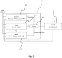
- Figure 2 shows the solution according to the present invention.
- Identical reference numerals or annotations denote the same elements as in Figure 1 .
- MON channel 2.2 is devised differently than in the prior art: Instead of simply comparing u (from COM channel 2.1) with alternative control commands u MON (from MON channel 2.2, cf. Figure 1 ), MON channel 2.2 implements and continuously verifies the relation/criterion: x ⁇ ⁇ P ⁇ f x , ⁇ K x , 0 ⁇ 0 ⁇ x ⁇ > ⁇ , based on Lyapunov's method as explained further up.
- control command u is applied to the aircraft 1, i.e., its actuators.
- control command u from COM channel 2.1 is applied to the aircraft 1, i.e., its actuators.
- the COM channel 2.1 is isolated/passivated via switch 2.3 and backup controller 2.4 takes over, as described before.
- x denotes a physical state of aircraft 1, which state can be either directly measured (via sensors, not shown) or estimated (e.g., from sensor measurements).
- control command u from COM channel 2.1 is applied to the aircraft 1, i.e., its actuators.
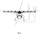
- FIG. 3 illustrates an aircraft 1 according to the present invention in some more detail.
- Aircraft 1 is devised in the form of an eVTOL multicopter, i.e., an aircraft with a plurality of actuators in the form of motor controllers for operating a plurality of electrically driven propulsion units 3a, only one of which motor controllers is denoted by reference numeral 3 for reason of clarity, which aircraft 1 has vertical take-off and landing capability and can be manned.
- the motor controllers 3, which are operatively connected with respective rotors and electric motors comprised in said propulsion units 3a, are controlled by providing them with corresponding control commands u by means of flight control system 2, as explained earlier. In this way, a flight behaviour of the entire aircraft 1 (in terms of attitude, altitude, velocity, etc.) can be controlled.
- Aircraft 1 may have further actuators (not shown), e.g., in connection with movable surfaces (flaps, wings, etc.) or a payload winch, that also influence flight behaviour of the entire aircraft 1 (in terms of attitude, altitude, velocity, etc.) and can be controlled by means of flight control system 2 and appropriate control commands u.
- actuators e.g., in connection with movable surfaces (flaps, wings, etc.) or a payload winch, that also influence flight behaviour of the entire aircraft 1 (in terms of attitude, altitude, velocity, etc.) and can be controlled by means of flight control system 2 and appropriate control commands u.
- Aircraft 1 further has a number of sensors for providing sensor data (measurement data) in connection with said physical state of aircraft 1, only one of which is denoted by reference numeral 4.
- Said sensors can comprise, e.g., temperature sensors, magnetometers, gyro sensors, accelerometers, atmospheric pressure sensors, etc., without limitation.
- Said sensors 4 provide corresponding data to flight control system 2, which data can be used to directly measure and/or estimate a current physical state x or part of such a state of aircraft 1. Said data is therefore said to be in relation with a physical state x or part of such a state of aircraft 1 and is denoted s in Figure 3 .
- the actual state x of aircraft 1 is established by flight control system 2, preferably by using data s from a variety of different sensors 4.
- Reference numeral 5 denotes the pilot input device that was mentioned earlier, which can take the form of a control stick, a touch screen, a pushbutton, a lever, a speech input device, etc., or any combination or number of the aforementioned elements.
- Said pilot input device 5 is used to provide said pilot input denoted w in Figures 1 through 3 to flight control system 2.
- pilot input device 5 has been described in terms of a device that can be operated by a human pilot, the invention is not limited in this respect. Pilot input could also be received from a robot, an auto-pilot and/or via remote control.
- Flight control system 2 is devised as explained earlier with reference to Figure 2 . It thus comprises at least one COM channel, at least one MON channel and at least one backup channel or backup controller.
- the MON channel is preferably devised to apply a Lyapunov method online, i.e., during flight of aircraft 1, in order to monitor functioning of said COM channel in terms of (aircraft) stability and integrity.
Landscapes
- Engineering & Computer Science (AREA)
- Aviation & Aerospace Engineering (AREA)
- Automation & Control Theory (AREA)
- Radar, Positioning & Navigation (AREA)
- Remote Sensing (AREA)
- Physics & Mathematics (AREA)
- General Physics & Mathematics (AREA)
- Feedback Control In General (AREA)
Abstract
The method comprises:
computing, for each actuator, a control command u, established according to at least one predetermined control law K for control of the flight surface or the propulsion unit operated by a given actuator and based on said pilot inputs w as well as on sensor measurements in relation to a physical state x of the aircraft (1) and providing respective control commands u to said actuators;
independently monitoring said control commands u by estimating and/or measuring a current physical state x of the aircraft (1) and comparing said physical state x with said control commands u, which comprises checking whether or not said control commands u stabilize the aircraft (1) in a stable state x in the absence of both disturbances d, i.e., d = 0, and pilot inputs, i.e., w = 0 according to at least one predefined criterion;
if said monitoring indicates a lack of stability, preventing transmission of said control commands u to said actuators and independently computing, for each actuator, a backup dissimilar control command established according to at least one predetermined backup control law for control of the flight surface or the propulsion unit operated by a given actuator and providing respective backup control commands to said actuators.
Description
- The invention relates to a method for flight control of an aircraft during flight, preferably an electrically propelled aircraft with vertical take-off and landing capability, which aircraft comprises a plurality of

claim 1. - The invention also relates to an aircraft, in particular a manned aircraft, preferably an electrically propelled aircraft with vertical take-off and landing capability, which aircraft comprises a plurality of

- Typically, the (direct) Lyapunov method is employed offline during an aircraft design stage to verify a given control law design and/or support a selection of control law parameters.
- In order to ensure the integrity and correctness of flight control commands in an aircraft during flight, i.e., online, a COM/MON design is often used, wherein a COM channel generates said control commands which are then analysed by an independent MON channel, which MON channel is typically devised as a functional copy of the COM channel.
- Examples for this approach can be found in
US 2011/0276199 A1 ,US 2018/0290730 A1 ,US 9,168,995 B2 CN 10193922 A . - As already stated above, a common approach to ensure that a control system in a safety-critical context, particularly in an aircraft, is fault-free at runtime is the COM/MON architecture. The COM channel performs the actual control task, while the MON channel monitors the validity of the actions of the COM channel and, if necessary, passivates the COM channel via a switch located at the output of the COM channel. To ensure continued operation in this case, a dissimilar backup controller takes over, which is shown in appended
Figure 1 . A typical application of this approach is, e.g., flight control in commercial aviation. - In general, the MON channel is an exact functional copy of the COM channel (see the above-referenced prior art). Thus, if there is a random fault in execution or a systematic implementation error on either the COM channel or the MON channel, this is identified by a mismatch between an output of the COM channel and an output of the MON channel. In this context, a dissimilar software implementation and dissimilar hardware/part numbers (particularly for any processors and memory modules) need to be deployed for COM channel and MON channel to ensure an absence of common or shared errors.
- The approach described above is suitable to detect and mitigate implementation errors and random hardware faults. However, design errors on the functional or logical level, e.g., software design, are usually not noticed when the MON channel is an exact functional copy of the COM channel, since in this case a design error can affect both channels. To prevent this problem, additional design error monitors can be implemented. In this case, a dissimilar logic is usually implemented to check the correctness of the system outputs for given system inputs at each point in time.
- The design of flight control laws presents a particular challenge in this context: For flight control laws, the system outputs to be checked usually depend on a large number of system inputs, and the relationship between inputs and outputs is typically complex and often nonlinear. Verifying the correctness of outputs with dissimilar logic is therefore non-trivial.
- A main goal of flight control laws is to stabilize the flight motion, i.e., the motion of the aircraft during flight. An intuitive idea for a design error monitor is thus to monitor the flight motion in order to detect a reduction in stability and/or controller performance. One problem with this approach resides in the fact that not only design errors/faults in the control law but also external disturbances (e.g., gusts) as well as errors/faults in other aircraft systems or components (e.g., the aircraft's actuators or sensors) can lead to reduced aircraft stability or reduced flight controller performance.
- A poorly designed design error monitor might falsely detect an allegedly erroneous COM behavior, which could lead to channel isolation in case of challenging scenarios such as significant external disturbance and/or errors/faults outside the control channel. The resulting hand-over to the dissimilar backup controller in such a situation presents a significant risk as (a) the transition typically causes a transient and (b) the backup control logic is typically somewhat simpler and less performant.
- To this end and due to a lack of systemic methods to derive design error monitors for control laws, the definition of design error monitors presents a significant challenge in the development of flight control laws.
- It is the object of the present invention to provide a method and an aircraft of the above-defined type that can achieve robust detection of both design and implementation errors in the flight controls logics even in the presence of external disturbances (e.g., gusts) as well as in the presence of errors/faults in other aircraft systems or components (e.g., actuators or sensors) during flight, i.e., online.
- This object is achieved by means of a method as defined by appended
claim 1 and by an aircraft as defined in appended claim 8. - Advantageous further developments are defined in the respective dependent claims.
- According to a first aspect of the invention, a method for flight control of an aircraft during flight, preferably an electrically propelled aircraft with vertical take-off and landing capability, which aircraft comprises a plurality of

- computing, for each actuator, a control command established according to at least one predetermined control law for control of the flight surface or the propulsion unit controlled/operated by a given actuator and based on said pilot inputs w as well as on sensor measurements in relation to a physical state x of the aircraft and providing respective control commands u,u ∈ RN to said actuators;
- independently monitoring said control commands u by estimating and/or measuring a current physical state x of the aircraft and comparing said physical state x with said control commands u, which comprises checking whether or not said control commands u stabilize the aircraft in a stable state x for time t → ∞ in the absence of both disturbances d, i.e., d = 0, and pilot inputs, i.e., w = 0 according to at least one predefined criterion;
- if said monitoring indicates a lack of stability, preventing transmission of said control commands u to said actuators and independently computing, for each actuator, a backup control command established according to at least one predetermined backup control law for control of the flight surface or the propulsion unit controlled/operated by a given actuator and providing respective backup control commands to said actuators.
- In other words, said control commands u, which are typically generated by a COM channel, are independently monitored, i.e., by means of an entity that is different in design from said COM channel, in particular a MON channel, by estimating and/or measuring a current physical state x of the aircraft and comparing said physical state x with said control commands u. This comparison includes checking, repeatedly during flight (i.e., online), whether or not said control commands u tend to stabilize the aircraft in a stable state x for time t, t → ∞, in the absence of both disturbances d, i.e., d = 0, and pilot inputs w, i.e., w = 0, according to said at least one predefined criterion.
- According to a second aspect of the invention, an aircraft, in particular a manned aircraft, preferably an electrically propelled aircraft with vertical take-off and landing capability, which aircraft comprises a plurality of

- a flight control system for controlling a flight of the aircraft by means of said actuators;
- at least one sensor for measuring a current physical state x of the aircraft and for providing corresponding measurement data to said flight control system;
- said pilot input device in operative connection with the flight control system;
- the flight control system being devised for augmenting a pilot input w for enhanced robustness to detect design and implementation errors;
- the flight control system preferably having multiple independent channels including at least one or more primary control channel(s) generating control commands u, u ∈ RN for the N actuators, which control commands u are the result of a control law implemented on a given primary control channel, which primary control channel is configured to calculate said control commands u based on said pilot inputs w and said measurement data;
- wherein at least one independent monitoring channel is provided and configured to receive and to monitor an output u of said at least one or each primary control channel, wherein said monitoring channel is configured to estimate and/or determine said current physical state x of the aircraft from said measurement data and is further configured to check whether or not said received control commands u stabilize the aircraft in a stable state for time t → ∞ in the absence of both disturbances d, i.e., d = 0, and pilot inputs, i.e., w = 0 according to at least one predefined criterion;
- which monitoring channel is further devised to isolate said primary control channel from the actuators, e.g., by operating a dedicated switch, based on said at least one predefined criterion;
- wherein preferably, if all primary control channels are isolated, a further independent backup control channel of the flight control system is devised to take over generation of control commands u, u ∈ RN for the N actuators.
- In other words, said at least one independent monitoring channel (the MON channel) serves to receive and to monitor said output u of said at least one or each primary control channel (the COM channel). Said monitoring channel is further configured to estimate and/or determine said current physical state x of the aircraft from said measurement data (sensor data). Based on said estimated and/or measured state, the MON channel is then able to check (online, i.e., during flight) whether or not said received control commands u tend to stabilize the aircraft in a stable state for time t, t → ∞, and in the absence of both disturbances d, i.e., d = 0, and pilot inputs w, i.e., w = 0, according to said at least one predefined criterion.
- In the context of the present invention, a manned aircraft is considered as a particular embodiment, which aircraft is controlled by means of a flight control system. The pilot provides the pilot input w to the flight control system, which pilot input is preferably augmented by the flight control system for enhanced robustness to detect design and implementation errors. To meet the high safety requirements in terms of integrity and availability, the flight control system preferably has multiple independent channels. One or more COM channel(s) generate(s) control commands u ∈ RN for the aircraft's N actuators,

- Said control commands u are typically presented in the form of a vector with N components, i.e., one component for each actuator. In the present specification, both singular and plural forms are thus used as synonyms to designate said control commands u.
- Therefore, the above-defined feature of "computing, for each actuator, a control command u, u ∈ RN " shall be understood in such a way that said computed command vector comprises a command (or corresponding component) for each one of said plurality of actuators.
- Let

- The flight control problem, as implemented by means of an embodiment of the method according to the invention, can then be stated as follows: provide a control command vector u such that the undisturbed system (i.e., d = 0) converges asymptotically to a stationary equilibrium condition x 0 in absence of pilot inputs (i.e., w = 0), i.e., t → ∞ : x → x 0 for d = w = 0, where 0 = f(x 0, u 0, 0) exists with u 0 denoting a trim control, i.e., control commands for said trim surfaces/tabs.
- In the following, x 0 = 0 is assumed. If this is not the case, the system can be simply transformed by setting

- A known approach to solve the flight control problem, which approach can also be used in an embodiment of the present invention, reads

- The (direct) Lyapunov method can be used to discuss various types of stability for the solutions of differential equations describing dynamical systems. The most important type is that concerning the stability of solutions in the vicinity of a point of equilibrium. This problem may be addressed by means of the theory of Aleksandr Lyapunov, cf. https://en.wikipedia.org/wiki/Lyapunov_stability, hence the name, which introduces so-called (quadratic) Lyapunov functions.
- Let V = x T · P · x denote a quadratic Lyapunov function with P = P T > 0, i.e., the relation: V > 0: ∥x∥ > 0 holds. An undisturbed control loop is asymptotically stable in the absence of pilot inputs with respect to the equilibrium condition x 0 (i.e., t → ∞ : x → x 0 for d = w = 0) if the following relation is true:

- A condition for exponential stability, which specifies the rate of convergence and is thus a more stringent condition than asymptotic stability (assuming ∥x(t)∥ ≤ β · e-λt for d = w = 0 with decay rate λ ≥ 0), reads

- For λ = 0 this equals asymptotic stability as a special case.
- The concept of using a scalar function V(x) to assess the stability of a dynamic system ẋ = g(x) with repsect to an equilibrium condition x 0 with 0 = g(x 0) is known as the above-mentioned (direct) method of Lyapunov, cf., e.g., Khalil, H.K. (1996). Nonlinear systems. Prentice Hall Upper Saddle River, NJ, Theorem 3.1 .
- In the context of the invention, a safety-critical control problem, such as flight control of a manned aircraft, is considered where the integrity of the controller output, i.e., the control commands u, must be ensured. Therefore, a COM/MON system architecture is used in which the MON channel monitors the validity of the commands u generated by the COM channel and isolates the output if necessary.
- The MON channel is preferably designed as follows:
- It has an independent design with respect to the COM channel. This preferably means that there are no shared logics, particularly the COM channel's control law K(x) shall not be used explicitly. This enables to not only to identify implementation errors and random hardware faults, but also design errors in the control law, which is typically the most complex algorithm or logic of the COM channel.
- No explicit use of the disturbance d, since it is typically unknown.
- Note that convergence of x -> 0 is not a suitable MON channel criterion, since an unknown non-zero perturbation (i.e., d ≠ 0) would negate this approach.
- In a preferred embodiment of the invention, the following solution is proposed: the MON channel uses x (i.e., said estimated and/or measured aircraft state) and u (as output from the COM channel) as input. The MON channel then checks whether or not the control command u issued by the COM channel would asymptotically stabilize the unperturbed system (d = 0) if pilot inputs are not present (w = 0).
- For instance, this is the case if the
relation 
holds, which follows from u = w - K(x) = -K(x) for w = 0. The parameter ε > 0 can be advantageously used as a criterion to pause the monitoring if the state x is (too) close to theequilibrium condition 0, in which case the comparison is numerically not robust. For ∥x∥ ≤ ε the comparison is thus preferably paused. - On the other hand, this is equivalent to stating that the state vector x has converged, and thus the COM control law has fulfilled its purpose. In case a
disturbance d # 0 or a pilot input w ≠ 0 leads to an excitement such that ∥x∥ > ε, the monitoring preferably resumes. - In a similar way, in another embodiment of the invention the more stringent condition for exponential stability can be checked by the MON channel, which then uses the
relation 
- Thus, with the proposed systematic approach according to the invention, integrity of the control law in the COM channel can be independently checked without knowing the disturbances d. A predefined criterion is used to check whether the control command u provided by the COM channel stabilizes the unperturbed system in the absence of pilot inputs (i.e., w = 0) ẋ = f(x, -K(x),0) for the given state x. This follows from ẋ = f(x, u, d), where u = w - K(x) = -K(x), and works independently of any unknown external disturbances d.
- The following embodiments have proven particularly advantageous:
In a preferred embodiment of the method according to the invention said at least one predefined criterion is met if
wherein
wherein V = x T · P · x denotes a quadratic Lyapunov function with P = P T > 0, so that the relation: V > 0: ∥x∥ > 0 holds and ε denotes a numerical parameter > 0. - This ensures stable asymptotic behaviour of aircraft control, i.e., the aircraft tends to acquire a stable state, as explained above.
- A corresponding embodiment of the aircraft according to the invention said monitoring channel is configured to verify the
relation 
wherein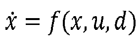
wherein V = x T · P · x denotes a quadratic Lyapunov function with P = P T > 0, so that the relation: V > 0: ∥x∥ > 0 holds, and ε denotes a numerical parameter > 0. - In another preferred embodiment of the method according to the invention said at least one predefined criterion is met if

wherein
- wherein V = x T · P · x denotes a quadratic Lyapunov function with P = P T > 0, so that the relation: V > 0: ∥x∥ > 0 holds and ε denotes a numerical parameter > 0;
- wherein it is assumed that ∥x(t)∥ ≤ β · e-λt for d = w = 0 with a decay rate λ ≥ 0 and /3 = const.
- This criterion demands exponential behaviour and is thus stricter than the criterion presented before.
- In a corresponding embodiment of the aircraft according to the invention said monitoring channel is configured to verify the
relation 
wherein
- wherein V = x T · P · x denotes a quadratic Lyapunov function with P = P T > 0, so that the relation: V > 0: ∥x∥ > 0 holds, and ε denotes a numerical parameter > 0;
- wherein it is assumed that ∥x(t)∥ ≤ β · e-λt for d = w = 0 with a decay rate λ ≥ 0 and /3 = const.
- In yet another preferred embodiment of the method according to the invention said parameter ε is used as a criterion to pause the monitoring if the state x is close to an equilibrium condition x = 0, i.e., for ∥x∥ ≤ ε.
- In this region, the system can be numerically unstable, which shall be avoided. Furthermore, the state x has proven to be convergent, which is the required result.
- In a corresponding embodiment of the aircraft according to the invention said monitoring channel is configured to use said parameter ε as a criterion for to pause its monitoring if the state x is close to an equilibrium condition x = 0, i.e., for ∥x∥ ≤ ε.
- In a highly preferred embodiment of the method according to the invention the comparison is thus paused for ∥x∥ ≤ ε and said respective control commands u,u ∈ RN are provided to said actuators.
- In a corresponding embodiment of the aircraft according to the invention said monitoring channel is therefore configured to pause the comparison for ∥x∥ ≤ ε and to allow provision of said control commands u, u ∈ RN to said actuators.
- In another highly preferred embodiment of the method according to the invention the monitoring resumes in case that a
disturbance d # 0 and/or pilot input w ≠ 0 leads to an excitement of the aircraft such that ∥x∥ > ε. - In this case, the systematic approach according to the invention is advantageously employed to provide increased robustness to detect design and implementation errors in the flight control logic.
- In a corresponding embodiment of the aircraft according to the invention in case that a
disturbance d # 0 and/or pilot input w ≠ 0 leads to an excitement of the aircraft such that ∥x∥ > ε, said monitoring channel is configured to resume the monitoring. - In still another highly preferred embodiment of the method according to the invention said control commands are calculated based on a relation

- This further helps to enhance robustness to detect design and implementation errors in the flight control logics.
- In a corresponding embodiment of the aircraft according to the invention said primary control channel is configured to implement a relation

- Further advantages and characteristics of the present invention will become apparent from the following description of preferred embodiments with reference to the attached drawings.
-
Figure 1 shows an aircraft having a flight control system as known from the prior art for comparison; -
Figure 2 shows an aircraft according to the present invention having an improved flight control system; and -
Figure 3 shows further features of an aircraft according to the present invention. - As shown in
Figure 1 , which represents the prior art, anaircraft 1, which comprises a plurality of actuators (not shown) for operating movable flight surfaces and/or propulsion units (not shown), is controlled during flight with respect to said actuators, i.e., said flight surfaces and propulsion units, by means of aflight control system 2, whichflight control system 2 is actually, i.e., physically, comprised withinaircraft 1. -
Flight control system 2 presents a COM/MON architecture comprising a primary control or COM channel ("COM") 2.1 and an independent monitoring or MON channel ("MON") 2.2. The COM channel 2.1 performs the actual control task and provides corresponding control commands u = w - K(x) to the actuators, while the MON channel 2.2 monitors the validity of the actions of the COM channel, i.e., the validity of the control commands generated by the COM channel 2.1 and, if necessary, passivates (or isolates) the COM channel via a switch 2.3 located at the output of the COM channel 2.1, so that the COM channel cannot provide control commands to the aircraft (or actuators). This is shown inFigure 1 by annotation ("Isolate COM (y/n)"). To ensure continued operation in this case,flight control system 2 further comprises a dissimilar backup controller ("BACKUP") 2.4 that takes over aircraft control and provides backup control commands u dissimilar toaircraft 1, i.e., said actuators. - All of said channels or controllers 2.1, 2.2, 2.4 are devised as programmable computing devices including the required hardware (processors, memory units, etc.) and software/firmware, as known to any skilled person, although this is not shown in any detail for reason of clarity.
- As already explained, aircraft pilot provides pilot input w to all three channels 2.1, 2.2 and 2.4 through a pilot input device (not shown), which channels implement a (flight) control law K(x), wherein x denotes a physical state of
aircraft 1, which state can be either directly measured (via sensors, not shown) or estimated (e.g., from sensor measurements). Typically, said control law is used by COM channel 2.1 to augment the pilot input w according to the equation
- For the MON channel 2.2 and the backup controller 2.4 this equation reads uMON = w - K(x) and u dissimilar = Kdissimilar (x,w), respectively. In this way, a more generic control law structure is considered for backup. If Kdissimilar = w - K(x) is chosen, the primary control structure is retained as a special case for backup, too.
- The aircraft's physical state x changes with time according to the equation

- There can be more than one COM channel 2.1, and backup controller 2.4 is only used if all existing COM channels have been passivated previously, as explained above.
- In general, the MON channel 2.2 is an exact functional copy of the COM channel 2.1. Thus, if there is a random fault in execution or a systematic implementation error on either the COM channel 2.1 or the MON channel 2.2, this is identified by a mismatch between an output of the COM channel 2.1 (i.e., control command u) and an output of the MON channel 2.2 (i.e., control command uMON ), cf. annotation "Compare u and uMON " in
Figure 1 . In this context, a dissimilar software implementation and dissimilar hardware/part numbers (particularly for any processors and memory modules) is used for COM channel 2.1 and MON channel 2.2, respectively, to ensure an absence of common or shared errors. -
Figure 2 , in contrast, shows the solution according to the present invention. In the following, only the differences with respect to the prior art will be discussed. Identical reference numerals or annotations denote the same elements as inFigure 1 . - As can be gathered from
Figure 2 , the MON channel 2.2 is devised differently than in the prior art:
Instead of simply comparing u (from COM channel 2.1) with alternative control commands uMON (from MON channel 2.2, cf.Figure 1 ), MON channel 2.2 implements and continuously verifies the relation/criterion:
- If said relation is true, i.e., if said criterion is met, then the aircraft's state is assumed to be asymptotically stable (for t → ∞), which assumption holds even in case of non-negligible disturbance (d ≠ 0) and/or pilot input (w ≠ 0). In this case, control command u is applied to the
aircraft 1, i.e., its actuators. - Instead of the above criterion, another relation/criterion (not shown in
Figure 2 ) can be used, which is stricter in terms of required stability:
- If said other criterion is met, i.e., if the corresponding relation is true, then the aircraft's state is assumed to be exponentially stable (for t → ∞), which assumption holds even in case of non-negligible disturbance (d ≠ 0) and or pilot input (w ≠ 0). In this case, too, control command u from COM channel 2.1 is applied to the
aircraft 1, i.e., its actuators. - If the implemented criterion is not met, then the COM channel 2.1 is isolated/passivated via switch 2.3 and backup controller 2.4 takes over, as described before.
- As before, x denotes a physical state of
aircraft 1, which state can be either directly measured (via sensors, not shown) or estimated (e.g., from sensor measurements). The output of "aircraft block" 1 is x, which actually results from an integration of x = f(x,u,d), i.e.,
block 1, as known to the skilled person. - In the special case of the aircraft state x being too close to an equilibrium condition x = 0, i.e., for ∥x∥ ≤ ε, the flight control system can be numerically unstable, which shall be avoided. Furthermore, the state x has proven to be convergent towards said equilibrium condition, which is the required result.
- Therefore, in such a situation the monitoring (MON) channel 2.2 is configured to pause its monitoring based on said parameter ε if the aircraft state x is close to an equilibrium condition x = 0, i.e., for ∥x∥ ≤ ε. In this case, too, control command u from COM channel 2.1 is applied to the
aircraft 1, i.e., its actuators. - If ∥x∥ becomes greater than ε, e.g., in case of a disturbance, then the monitoring action of MON channel 2.2 is resumed.
-
Figure 3 illustrates anaircraft 1 according to the present invention in some more detail. -
Aircraft 1 is devised in the form of an eVTOL multicopter, i.e., an aircraft with a plurality of actuators in the form of motor controllers for operating a plurality of electrically driven propulsion units 3a, only one of which motor controllers is denoted by reference numeral 3 for reason of clarity, whichaircraft 1 has vertical take-off and landing capability and can be manned. The motor controllers 3, which are operatively connected with respective rotors and electric motors comprised in said propulsion units 3a, are controlled by providing them with corresponding control commands u by means offlight control system 2, as explained earlier. In this way, a flight behaviour of the entire aircraft 1 (in terms of attitude, altitude, velocity, etc.) can be controlled. -
Aircraft 1 may have further actuators (not shown), e.g., in connection with movable surfaces (flaps, wings, etc.) or a payload winch, that also influence flight behaviour of the entire aircraft 1 (in terms of attitude, altitude, velocity, etc.) and can be controlled by means offlight control system 2 and appropriate control commands u. -
Aircraft 1 further has a number of sensors for providing sensor data (measurement data) in connection with said physical state ofaircraft 1, only one of which is denoted byreference numeral 4. Said sensors can comprise, e.g., temperature sensors, magnetometers, gyro sensors, accelerometers, atmospheric pressure sensors, etc., without limitation. Saidsensors 4 provide corresponding data toflight control system 2, which data can be used to directly measure and/or estimate a current physical state x or part of such a state ofaircraft 1. Said data is therefore said to be in relation with a physical state x or part of such a state ofaircraft 1 and is denoted s inFigure 3 . The actual state x ofaircraft 1 is established byflight control system 2, preferably by using data s from a variety ofdifferent sensors 4. -
Reference numeral 5 denotes the pilot input device that was mentioned earlier, which can take the form of a control stick, a touch screen, a pushbutton, a lever, a speech input device, etc., or any combination or number of the aforementioned elements. Saidpilot input device 5 is used to provide said pilot input denoted w inFigures 1 through 3 toflight control system 2. - Although
pilot input device 5 has been described in terms of a device that can be operated by a human pilot, the invention is not limited in this respect. Pilot input could also be received from a robot, an auto-pilot and/or via remote control. -
Flight control system 2 is devised as explained earlier with reference toFigure 2 . It thus comprises at least one COM channel, at least one MON channel and at least one backup channel or backup controller. The MON channel is preferably devised to apply a Lyapunov method online, i.e., during flight ofaircraft 1, in order to monitor functioning of said COM channel in terms of (aircraft) stability and integrity. - Although the invention has been described with reference to an aircraft and its behaviour during flight as an exemplary embodiment, the skilled person will appreciate that the concept underlying the present invention can be easily extended to any system or plant the overall behaviour of which is governed or controlled by a plurality of actuators, which actuators are themselves controlled by means of a control system that comprises at least one primary control channel and at least one monitoring channel, which monitoring channel is devised to monitor/verify operation of said primary control channel in accordance with the present invention.
Claims (14)
- A method for flight control of an aircraft (1) during flight, preferably an electrically propelled aircraft (1) with vertical take-off and landing capability, which aircraft (1) comprises a plurality of
 computing, for each actuator (3), a control command u, u ∈ RN established according to at least one predetermined control law K for control of the flight surface or the propulsion unit (3a) operated by a given actuator (3) and based on said pilot inputs w as well as on sensor measurements in relation to a physical state x of the aircraft (1) and providing respective control commands u to said actuators (3);independently monitoring said control commands u by estimating and/or measuring a current physical state x of the aircraft (1) and comparing said physical state x with said control commands u, which comprises checking whether or not said control commands u stabilize the aircraft (1) in a stable state x for time t → ∞ in the absence of both disturbances d, i.e., d = 0, and pilot inputs, i.e., w = 0 according to at least one predefined criterion;if said monitoring indicates a lack of stability, preventing transmission of said control commands u to said actuators (3) and independently computing, for each actuator (3), a backup control command udissimilar established according to at least one predetermined backup control law Kdissimilar for control of the flight surface or the propulsion unit (3a) operated by a given actuator (3) and providing respective backup control commands udissimilar to said actuators (3).
 - The method of claim 1, wherein said at least one predefined criterion is met if

wherein
wherein V = x T · P · x denotes a quadratic Lyapunov function with P = P T > 0, so that the relation: V > 0: ∥x∥ > 0 holds and ε denotes a numerical parameter > 0. - The method of claim 1, wherein said at least one predefined criterion is met if

wherein wherein V = x T · P · x denotes a quadratic Lyapunov function with P = P T > 0, so that the relation: V > 0: ∥x∥ > 0 holds and ε denotes a numerical parameter > 0;wherein it is assumed that ∥x(t)∥ ≤ β · e-λt for d = w = 0 with a decay rate λ > 0 and β = const.
 - The method of claim 2 or 3, wherein said parameter ε is used as a criterion to pause the monitoring if the state x is close to an equilibrium condition x = 0, i.e., for ∥x∥ ≤ ε.
- The method of any one of claims 2 through 4, wherein for ∥x∥ ≤ ε the comparison is paused and said respective control commands u, u ∈ RN are provided to said actuators (3).
- The method of claim 5, wherein in case that a disturbance d # 0 and/or pilot input w ≠ 0 leads to an excitement of the aircraft (1) such that ∥x∥ > ε, the monitoring resumes.
- The method of any one of claims 1 through 6, wherein said control commands u are calculated based on a relation

- An aircraft (1), in particular a manned aircraft, preferably an electrically propelled aircraft (1) with vertical take-off and landing capability, which aircraft (1) comprises a plurality of
 a flight control system (2) for controlling a flight of the aircraft (1) by means of said actuators (3);at least one sensor (4) for measuring a current physical state x of the aircraft (1) and for providing corresponding measurement data s to said flight control system (2);said pilot input device (5) in operative connection with the flight control system (2);the flight control system (2) being devised for augmenting a pilot input w for enhanced robustness to detect design and implementation errors;the flight control system (2) preferably having multiple independent channels (2.1, 2.2, 2.4) including at least one or more primary control channel(s) (2.1) generating control commands u, u ∈ RN for the N actuators (3), which control commands u are the result of a control law K = K(x) implemented on a given primary control channel (2.1), which primary control channel (2.1) is configured to calculate said control commands u based on said pilot inputs w and said measurement data s;wherein at least one independent monitoring channel (2.2) is provided and configured to receive and to monitor an output u of said at least one or each primary control channel (2.1), wherein said monitoring channel (2.2) is configured to estimate and/or determine said current physical state x of the aircraft (1) from said measurement data s and is further configured to check whether or not said received control commands u stabilize the aircraft (1) in a stable state for time t → ∞ in the absence of both disturbances d, i.e., d = 0, and pilot inputs, i.e., w = 0 according to at least one predefined criterion;which monitoring channel (2.2) is further devised to isolate said primary control channel (2.1) from the actuators (3) based on said at least one predefined criterion;wherein preferably, if all primary control channels (2.1) are isolated, a further independent backup control channel (2.4) of the flight control system (2) is devised to take over generation of control commands u,u ∈ RN for the N actuators (3).
 - The aircraft (1) of claim 8, wherein said monitoring channel (2.2) is configured to verify the relation

wherein
wherein V = x T · P · x denotes a quadratic Lyapunov function with P = P T > 0, so that the relation V > 0: ∥x∥ > 0 holds, and ε denotes a numerical parameter > 0. - The aircraft (1) of claim 8, wherein said monitoring channel (2.2) is configured to verify the relation

wherein wherein V = x T · P · x denotes a quadratic Lyapunov function with P = P T > 0, so that the relation: V > 0: ∥x∥ > 0 holds, and ε denotes a numerical parameter > 0;wherein it is assumed that ∥x(t)∥ ≤ β · e-λt for d = w = 0 with a decay rate λ > 0 and β = const.
 - The aircraft (1) of claim 9 or 10, wherein said monitoring channel (2.2) is configured to use said parameter ε as a criterion for to pause its monitoring if the state x is close to an equilibrium condition x = 0, i.e., for ∥x∥ ≤ ε.
- The aircraft (1) of any one of claims 9 through 11, wherein said monitoring channel (2.2) is configured to pause the comparison for ∥x∥ ≤ ε and to allow provision of said control commands u, u ∈ RN to said actuators (3).
- The aircraft (1) of claim 12, wherein in case that a disturbance d # 0 and/or pilot input w ≠ 0 leads to an excitement of the aircraft (1) such that ∥x∥ > ε, said monitoring channel (2;2) is configured to resume the monitoring.
- The aircraft (1) of any one of claims 8 through 13, wherein said primary control channel (2.1) is configured to implement a relation

Priority Applications (3)
| Application Number | Priority Date | Filing Date | Title |
|---|---|---|---|
| EP23161882.8A EP4432040B1 (en) | 2023-03-14 | 2023-03-14 | Method for run time flight stability control of an aircraft and aircraft controlled using same |
| US18/421,286 US12468312B2 (en) | 2023-03-14 | 2024-01-24 | Aircraft and method for flight control of an aircraft during flight |
| CN202410295178.7A CN118655907A (en) | 2023-03-14 | 2024-03-14 | Aircraft and method for flight control of an aircraft during flight |
Applications Claiming Priority (1)
| Application Number | Priority Date | Filing Date | Title |
|---|---|---|---|
| EP23161882.8A EP4432040B1 (en) | 2023-03-14 | 2023-03-14 | Method for run time flight stability control of an aircraft and aircraft controlled using same |
Publications (2)
| Publication Number | Publication Date |
|---|---|
| EP4432040A1 true EP4432040A1 (en) | 2024-09-18 |
| EP4432040B1 EP4432040B1 (en) | 2026-02-25 |
Family
ID=85641157
Family Applications (1)
| Application Number | Title | Priority Date | Filing Date |
|---|---|---|---|
| EP23161882.8A Active EP4432040B1 (en) | 2023-03-14 | 2023-03-14 | Method for run time flight stability control of an aircraft and aircraft controlled using same |
Country Status (3)
| Country | Link |
|---|---|
| US (1) | US12468312B2 (en) |
| EP (1) | EP4432040B1 (en) |
| CN (1) | CN118655907A (en) |
Cited By (1)
| Publication number | Priority date | Publication date | Assignee | Title |
|---|---|---|---|---|
| CN120386395A (en) * | 2025-04-23 | 2025-07-29 | 哈尔滨工业大学 | A method for selecting the aircraft's spin angular velocity based on dynamic stability criteria |
Families Citing this family (3)
| Publication number | Priority date | Publication date | Assignee | Title |
|---|---|---|---|---|
| US12498719B2 (en) * | 2023-10-31 | 2025-12-16 | National Formosa University | On-board redundant controller and standby aviation sensors in-flight reconfigurable autonomous flight system |
| US12330772B1 (en) | 2024-08-23 | 2025-06-17 | Archer Aviation Inc. | Fault-tolerant multi-processor systems and methods for an aircraft |
| CN119828768A (en) * | 2024-12-31 | 2025-04-15 | 中国飞机强度研究所 | Aircraft system state estimation method based on adaptive interval observer |
Citations (4)
| Publication number | Priority date | Publication date | Assignee | Title |
|---|---|---|---|---|
| US20110276199A1 (en) | 2010-05-10 | 2011-11-10 | Airbus Operations (S.A.S.) | Flight control system and aircraft comprising it |
| US9168995B2 (en) | 2012-10-05 | 2015-10-27 | Airbus Operations (Sas) | Flight control system using simplex computers and aircraft comprising same |
| US20180290730A1 (en) | 2017-04-07 | 2018-10-11 | Airbus Operations Sas | Aircraft flight control system |
| WO2021224185A1 (en) * | 2020-05-05 | 2021-11-11 | Thales | Method for controlling a robot-aircraft and corresponding control system |
Family Cites Families (3)
| Publication number | Priority date | Publication date | Assignee | Title |
|---|---|---|---|---|
| FR2927308B1 (en) | 2008-02-08 | 2010-10-22 | Airbus France | DISTRIBUTED FLIGHT CONTROL SYSTEM. |
| EP3548977A1 (en) * | 2016-11-30 | 2019-10-09 | Bombardier Inc. | Aircraft control system with residual error containment |
| DE102020107172A1 (en) * | 2020-03-16 | 2021-09-16 | Volocopter Gmbh | A method for controlling an aircraft, a control device for an aircraft and an aircraft with such a control device |
-
2023
- 2023-03-14 EP EP23161882.8A patent/EP4432040B1/en active Active
-
2024
- 2024-01-24 US US18/421,286 patent/US12468312B2/en active Active
- 2024-03-14 CN CN202410295178.7A patent/CN118655907A/en active Pending
Patent Citations (4)
| Publication number | Priority date | Publication date | Assignee | Title |
|---|---|---|---|---|
| US20110276199A1 (en) | 2010-05-10 | 2011-11-10 | Airbus Operations (S.A.S.) | Flight control system and aircraft comprising it |
| US9168995B2 (en) | 2012-10-05 | 2015-10-27 | Airbus Operations (Sas) | Flight control system using simplex computers and aircraft comprising same |
| US20180290730A1 (en) | 2017-04-07 | 2018-10-11 | Airbus Operations Sas | Aircraft flight control system |
| WO2021224185A1 (en) * | 2020-05-05 | 2021-11-11 | Thales | Method for controlling a robot-aircraft and corresponding control system |
Non-Patent Citations (1)
| Title |
|---|
| LUI SHA: "Using simplicity to control complexity", IEEE SOFTWARE, vol. 18, no. 4, 30 August 2001 (2001-08-30), USA, pages 20 - 28, XP055776948, ISSN: 0740-7459, DOI: 10.1109/MS.2001.936213 * |
Cited By (1)
| Publication number | Priority date | Publication date | Assignee | Title |
|---|---|---|---|---|
| CN120386395A (en) * | 2025-04-23 | 2025-07-29 | 哈尔滨工业大学 | A method for selecting the aircraft's spin angular velocity based on dynamic stability criteria |
Also Published As
| Publication number | Publication date |
|---|---|
| EP4432040B1 (en) | 2026-02-25 |
| US20240310850A1 (en) | 2024-09-19 |
| US12468312B2 (en) | 2025-11-11 |
| CN118655907A (en) | 2024-09-17 |
Similar Documents
| Publication | Publication Date | Title |
|---|---|---|
| EP4432040B1 (en) | Method for run time flight stability control of an aircraft and aircraft controlled using same | |
| US6389335B1 (en) | Fault tolerant automatic control system utilizing analytic redundancy | |
| EP0830647B1 (en) | Fault tolerant automatic control system utilizing analytic redundancy | |
| CN113247302B (en) | Methods and systems for monitoring the condition of VTOL aircraft | |
| US8185255B2 (en) | Robust control effector allocation | |
| US8849603B2 (en) | Systems and methods for control system verification and health assessment | |
| US8755956B2 (en) | Method and device for detecting the jamming of an aircraft control surface | |
| US9463868B2 (en) | Systems and methods for aircraft control surface hardover and disconnect protection | |
| CN113401337B (en) | Aircraft and control method and control device thereof | |
| Lombaerts et al. | Piloted simulator evaluation results of new fault-tolerant flight control algorithm | |
| Lu et al. | Active fault-tolerant control system using incremental backstepping approach | |
| Fradkov et al. | Adaptive passification-based fault-tolerant flight control | |
| Ignatyev et al. | Two-layer on-line parameter estimation for adaptive incremental backstepping flight control for a transport aircraft in uncertain conditions | |
| Stepanyan et al. | Stability and performance metrics for adaptive flight control | |
| Sørensen et al. | UAV fault-tolerant control by combined L 1 adaptive backstepping and fault-dependent control allocation | |
| Zolghadrit et al. | Turning theory to practice in model-based FDI: Successful application to new generation airbus aircraft | |
| Lungu et al. | Estimation of aircraft state during landing by means of multiple observers | |
| Riaz et al. | Fault Signal Detection of Linear Actuators based on Intelligent Remnant Filter | |
| Nguyen et al. | Stability, convergence, and verification and validation challenges of neural net adaptive flight control | |
| Tran et al. | Developing an approach for identifying and fixing faults of angular velocity sensors on aerial vehicles | |
| Sachs et al. | Monitoring of oscillatory failure cases for the reduction of structural loads in an aeroelastic aircraft | |
| Yue et al. | for Flight Parameters in Civil Aircraft FBW | |
| Gupta et al. | Performance monitoring and assessment of neuro-adaptive controllers for aerospace applications using a Bayesian approach | |
| Fu et al. | Fault detection for aircraft control surfaces using approximate input reconstruction | |
| CN111176252B (en) | Fault diagnosis method for concurrent actuator of hypersonic reentry overdrive system |
Legal Events
| Date | Code | Title | Description |
|---|---|---|---|
| PUAI | Public reference made under article 153(3) epc to a published international application that has entered the european phase |
Free format text: ORIGINAL CODE: 0009012 |
|
| STAA | Information on the status of an ep patent application or granted ep patent |
Free format text: STATUS: THE APPLICATION HAS BEEN PUBLISHED |
|
| AK | Designated contracting states |
Kind code of ref document: A1 Designated state(s): AL AT BE BG CH CY CZ DE DK EE ES FI FR GB GR HR HU IE IS IT LI LT LU LV MC ME MK MT NL NO PL PT RO RS SE SI SK SM TR |
|
| STAA | Information on the status of an ep patent application or granted ep patent |
Free format text: STATUS: REQUEST FOR EXAMINATION WAS MADE |
|
| 17P | Request for examination filed |
Effective date: 20250228 |
|
| 19U | Interruption of proceedings before grant |
Effective date: 20250301 |
|
| 19W | Proceedings resumed before grant after interruption of proceedings |
Effective date: 20250801 |
|
| REG | Reference to a national code |
Ref legal event code: R079 Ipc: G05D0001495000 Ref country code: DE Ref legal event code: R079 Ref document number: 602023012404 Country of ref document: DE Free format text: PREVIOUS MAIN CLASS: G05D0001080000 Ipc: G05D0001495000 |
|
| RAP3 | Party data changed (applicant data changed or rights of an application transferred) |
Owner name: VOLOCOPTER TECHNOLOGIES GMBH |
|
| RIC1 | Information provided on ipc code assigned before grant |
Ipc: G05D 1/495 20240101AFI20250902BHEP Ipc: G05D 1/86 20240101ALI20250902BHEP Ipc: G05D 105/22 20240101ALI20250902BHEP Ipc: G05D 109/25 20240101ALI20250902BHEP |
|
| GRAP | Despatch of communication of intention to grant a patent |
Free format text: ORIGINAL CODE: EPIDOSNIGR1 |
|
| STAA | Information on the status of an ep patent application or granted ep patent |
Free format text: STATUS: GRANT OF PATENT IS INTENDED |
|
| INTG | Intention to grant announced |
Effective date: 20251013 |
|
| GRAS | Grant fee paid |
Free format text: ORIGINAL CODE: EPIDOSNIGR3 |
|
| GRAA | (expected) grant |
Free format text: ORIGINAL CODE: 0009210 |
|
| STAA | Information on the status of an ep patent application or granted ep patent |
Free format text: STATUS: THE PATENT HAS BEEN GRANTED |
|
| AK | Designated contracting states |
Kind code of ref document: B1 Designated state(s): AL AT BE BG CH CY CZ DE DK EE ES FI FR GB GR HR HU IE IS IT LI LT LU LV MC ME MK MT NL NO PL PT RO RS SE SI SK SM TR |
|
| REG | Reference to a national code |
Ref country code: CH Ref legal event code: F10 Free format text: ST27 STATUS EVENT CODE: U-0-0-F10-F00 (AS PROVIDED BY THE NATIONAL OFFICE) Effective date: 20260225 Ref country code: GB Ref legal event code: FG4D |
|
| REG | Reference to a national code |
Ref country code: DE Ref legal event code: R096 Ref document number: 602023012404 Country of ref document: DE |
|
| REG | Reference to a national code |
Ref country code: IE Ref legal event code: FG4D |
|
| REG | Reference to a national code |
Ref country code: DE Ref legal event code: R082 Ref document number: 602023012404 Country of ref document: DE Representative=s name: BAUER, MARCUS, M.SC., DE |
|
| PGFP | Annual fee paid to national office [announced via postgrant information from national office to epo] |
Ref country code: AT Payment date: 20260301 Year of fee payment: 4 |
|
| P01 | Opt-out of the competence of the unified patent court (upc) registered |
Free format text: CASE NUMBER: UPC_APP_0009020_4432040/2026 Effective date: 20260306 |