EP4432038A1 - Method for surveilling an area of interest using drones - Google Patents
Method for surveilling an area of interest using drones Download PDFInfo
- Publication number
- EP4432038A1 EP4432038A1 EP23305358.6A EP23305358A EP4432038A1 EP 4432038 A1 EP4432038 A1 EP 4432038A1 EP 23305358 A EP23305358 A EP 23305358A EP 4432038 A1 EP4432038 A1 EP 4432038A1
- Authority
- EP
- European Patent Office
- Prior art keywords
- area
- interest
- drones
- sub
- cluster
- Prior art date
- Legal status (The legal status is an assumption and is not a legal conclusion. Google has not performed a legal analysis and makes no representation as to the accuracy of the status listed.)
- Granted
Links
Images


Classifications
-
- G—PHYSICS
- G06—COMPUTING OR CALCULATING; COUNTING
- G06V—IMAGE OR VIDEO RECOGNITION OR UNDERSTANDING
- G06V20/00—Scenes; Scene-specific elements
- G06V20/50—Context or environment of the image
- G06V20/52—Surveillance or monitoring of activities, e.g. for recognising suspicious objects
-
- G—PHYSICS
- G08—SIGNALLING
- G08G—TRAFFIC CONTROL SYSTEMS
- G08G5/00—Traffic control systems for aircraft
- G08G5/20—Arrangements for acquiring, generating, sharing or displaying traffic information
- G08G5/25—Transmission of traffic-related information between aircraft
-
- G—PHYSICS
- G05—CONTROLLING; REGULATING
- G05D—SYSTEMS FOR CONTROLLING OR REGULATING NON-ELECTRIC VARIABLES
- G05D1/00—Control of position, course, altitude or attitude of land, water, air or space vehicles, e.g. using automatic pilots
- G05D1/20—Control system inputs
- G05D1/24—Arrangements for determining position or orientation
- G05D1/247—Arrangements for determining position or orientation using signals provided by artificial sources external to the vehicle, e.g. navigation beacons
- G05D1/248—Arrangements for determining position or orientation using signals provided by artificial sources external to the vehicle, e.g. navigation beacons generated by satellites, e.g. GPS
-
- G—PHYSICS
- G05—CONTROLLING; REGULATING
- G05D—SYSTEMS FOR CONTROLLING OR REGULATING NON-ELECTRIC VARIABLES
- G05D1/00—Control of position, course, altitude or attitude of land, water, air or space vehicles, e.g. using automatic pilots
- G05D1/40—Control within particular dimensions
- G05D1/43—Control of position or course in two dimensions [2D]
-
- G—PHYSICS
- G05—CONTROLLING; REGULATING
- G05D—SYSTEMS FOR CONTROLLING OR REGULATING NON-ELECTRIC VARIABLES
- G05D1/00—Control of position, course, altitude or attitude of land, water, air or space vehicles, e.g. using automatic pilots
- G05D1/60—Intended control result
- G05D1/648—Performing a task within a working area or space, e.g. cleaning
- G05D1/6482—Performing a task within a working area or space, e.g. cleaning by dividing the whole area or space in sectors to be processed separately
-
- G—PHYSICS
- G05—CONTROLLING; REGULATING
- G05D—SYSTEMS FOR CONTROLLING OR REGULATING NON-ELECTRIC VARIABLES
- G05D1/00—Control of position, course, altitude or attitude of land, water, air or space vehicles, e.g. using automatic pilots
- G05D1/60—Intended control result
- G05D1/69—Coordinated control of the position or course of two or more vehicles
- G05D1/698—Control allocation
- G05D1/6987—Control allocation by centralised control off-board any of the vehicles
-
- G—PHYSICS
- G06—COMPUTING OR CALCULATING; COUNTING
- G06T—IMAGE DATA PROCESSING OR GENERATION, IN GENERAL
- G06T7/00—Image analysis
- G06T7/10—Segmentation; Edge detection
- G06T7/11—Region-based segmentation
-
- G—PHYSICS
- G06—COMPUTING OR CALCULATING; COUNTING
- G06V—IMAGE OR VIDEO RECOGNITION OR UNDERSTANDING
- G06V10/00—Arrangements for image or video recognition or understanding
- G06V10/20—Image preprocessing
- G06V10/25—Determination of region of interest [ROI] or a volume of interest [VOI]
-
- G—PHYSICS
- G06—COMPUTING OR CALCULATING; COUNTING
- G06V—IMAGE OR VIDEO RECOGNITION OR UNDERSTANDING
- G06V10/00—Arrangements for image or video recognition or understanding
- G06V10/70—Arrangements for image or video recognition or understanding using pattern recognition or machine learning
- G06V10/762—Arrangements for image or video recognition or understanding using pattern recognition or machine learning using clustering, e.g. of similar faces in social networks
-
- G—PHYSICS
- G06—COMPUTING OR CALCULATING; COUNTING
- G06V—IMAGE OR VIDEO RECOGNITION OR UNDERSTANDING
- G06V20/00—Scenes; Scene-specific elements
- G06V20/10—Terrestrial scenes
- G06V20/17—Terrestrial scenes taken from planes or by drones
-
- G—PHYSICS
- G08—SIGNALLING
- G08G—TRAFFIC CONTROL SYSTEMS
- G08G5/00—Traffic control systems for aircraft
- G08G5/20—Arrangements for acquiring, generating, sharing or displaying traffic information
- G08G5/21—Arrangements for acquiring, generating, sharing or displaying traffic information located onboard the aircraft
-
- G—PHYSICS
- G08—SIGNALLING
- G08G—TRAFFIC CONTROL SYSTEMS
- G08G5/00—Traffic control systems for aircraft
- G08G5/20—Arrangements for acquiring, generating, sharing or displaying traffic information
- G08G5/26—Transmission of traffic-related information between aircraft and ground stations
-
- G—PHYSICS
- G08—SIGNALLING
- G08G—TRAFFIC CONTROL SYSTEMS
- G08G5/00—Traffic control systems for aircraft
- G08G5/50—Navigation or guidance aids
- G08G5/53—Navigation or guidance aids for cruising
-
- G—PHYSICS
- G08—SIGNALLING
- G08G—TRAFFIC CONTROL SYSTEMS
- G08G5/00—Traffic control systems for aircraft
- G08G5/50—Navigation or guidance aids
- G08G5/55—Navigation or guidance aids for a single aircraft
-
- G—PHYSICS
- G08—SIGNALLING
- G08G—TRAFFIC CONTROL SYSTEMS
- G08G5/00—Traffic control systems for aircraft
- G08G5/70—Arrangements for monitoring traffic-related situations or conditions
- G08G5/72—Arrangements for monitoring traffic-related situations or conditions for monitoring traffic
- G08G5/723—Arrangements for monitoring traffic-related situations or conditions for monitoring traffic from the aircraft
-
- G—PHYSICS
- G05—CONTROLLING; REGULATING
- G05D—SYSTEMS FOR CONTROLLING OR REGULATING NON-ELECTRIC VARIABLES
- G05D2105/00—Specific applications of the controlled vehicles
- G05D2105/80—Specific applications of the controlled vehicles for information gathering, e.g. for academic research
- G05D2105/85—Specific applications of the controlled vehicles for information gathering, e.g. for academic research for patrolling or reconnaissance for police, security or military applications
-
- G—PHYSICS
- G05—CONTROLLING; REGULATING
- G05D—SYSTEMS FOR CONTROLLING OR REGULATING NON-ELECTRIC VARIABLES
- G05D2109/00—Types of controlled vehicles
- G05D2109/20—Aircraft, e.g. drones
- G05D2109/25—Rotorcrafts
- G05D2109/254—Flying platforms, e.g. multicopters
-
- G—PHYSICS
- G08—SIGNALLING
- G08G—TRAFFIC CONTROL SYSTEMS
- G08G5/00—Traffic control systems for aircraft
- G08G5/50—Navigation or guidance aids
- G08G5/57—Navigation or guidance aids for unmanned aircraft
-
- G—PHYSICS
- G08—SIGNALLING
- G08G—TRAFFIC CONTROL SYSTEMS
- G08G5/00—Traffic control systems for aircraft
- G08G5/50—Navigation or guidance aids
- G08G5/59—Navigation or guidance aids in accordance with predefined flight zones, e.g. to avoid prohibited zones
Definitions
- the present invention relates to a surveillance method for surveilling an area of interest using a set of drones.
- the invention further relates to computer program and to a surveillance system for implementing said surveillance method.
- the invention applies to the field of remote surveillance, and more specifically to geo-fencing.
- surveillance It is known to resort to a set (also referred to as "swarm") of autonomous drones to perform surveillance of an area of interest. Such surveillance may be needed in domains like disaster management, agriculture, or even oil and gas, or any other domain where there is a need to chart and explore known or unknown territory. Such surveillance may also be needed to perform geofencing, which involves detecting and tracking predetermined assets or targets in the area of interest.
- drone it is meant, in the context of the present invention, an unmanned vehicle. Such vehicle may be adapted to move on land, in the air, on water and/or underwater.
- drones provide several advantages over satellites and planes. For instance, a drone is generally much cheaper than a plane or a satellite. Moreover, contrary to satellites, upgrades can quickly be performed on a drone to provide it with sensors that are suitable for a given surveillance campaign. Another advantage lies in the fact that the repeat cycle of a drone (i.e., the duration between two successive instants at which the drone revisits a same location) can be made as low as desired, contrary to a satellite. Furthermore, a drone is generally less visible than a plane.
- a given drone may be compromised. This may result from weather conditions, geography topology, hardware malfunction or system failure. Besides, a given drone may need to redock on its base station for recharging or refueling.
- a purpose of the present invention is to overcome at least one of these drawbacks.
- Another purpose of the invention is to provide a surveillance method involving the use of a set of drones, wherein all the area of interest remains under surveillance, even if operation of part of the drones of the swarm is compromised, and without intervention of an operator.
- the present invention is a surveillance method of the aforementioned type, the surveillance method comprising monitoring a number of operational drones among the set of drones, and, if a change in the number of operational drones is detected, performing:
- the claimed method allows to adapt, in real time, and without the intervention of an operator, the number of sub-areas to the number of drones that are currently actually operational, that is to say the drones that are currently able to perform the desired surveillance task.
- Such real-time adaptation results in a surveillance method that is self-healing, i.e. that automatically compensates for the unpredictable unavailability of one or several drones.
- the surveillance method further includes one or more of the following features, taken individually or according to any technically possible combination:
- a computer program comprising instructions, which when executed by a computer, cause the computer to carry out the steps of the surveillance method as defined above.
- the computer program may be in any programming language such as C, C++, JAVA, Python, etc.
- the computer program may be in machine language.
- the computer program may be stored, in a non-transient memory, such as a USB stick, a flash memory, a hard-disc, a programmable electronic chip, etc.
- a non-transient memory such as a USB stick, a flash memory, a hard-disc, a programmable electronic chip, etc.
- the computer program may be stored in a computerized device such as a smartphone, a tablet, a computer, a server, a drone, etc.
- the computer program may schedule for routine update and refactor to ensure the performance quality.
- a surveillance system including a control unit and a set of drones for performing surveillance of an area of interest, the control unit being configured to monitor a number of operational drones among the set of drones, the control unit being further configured, if a change in the number of operational drones is detected, to:
- the control unit may be a personal device such as a smartphone, a tablet, a Smartwatch, a computer, any wearable electronic device, etc.
- the control unit may execute one or several applications to carry out the method according to the invention.
- the control unit may be loaded with, and configured to execute, the computer program according to the invention.
- the control unit may be installed on a local server at a ground station to communicate with drones.
- the control unit may be deployed in a cloud server and be connected to the drones and to a local ground station.
- the system data log may be recorded for future reference and system maintenance.
- the surveillance system further includes one or more of the following features, taken individually or according to any technically possible combination:
- a surveillance system 2 according to the invention is shown on figures 1 and 2 .
- the surveillance system 2 is configured to perform surveillance of an area of interest. More precisely, the limits of the area of interest have known geographic coordinates.
- the surveillance system 2 includes a swarm 4 of drones and a control unit 6 in communication with each other.
- the swarm of drones 4 includes at least one drone 8.
- Each drone 8 is an unmanned drone configured to autonomously perform surveillance of a sub-area of the area of interest to which said drone is affected.
- each drone 8 includes a surveillance module 10 and a communication module 12.
- the surveillance module 10 is configured to detect and track targets in the respective sub-area.
- the surveillance module 10 includes an acquisition stage, a processing stage and a location stage (not shown).
- the acquisition stage may be configured to acquire images of the respective sub-area.
- the processing stage may be configured to process the acquired images to detect the targets in said sub-area.
- the surveillance module 10 may be configured to acquire, for each target, a radio signal emitted by said target.
- said radio signal is a GPS (for "Global Positioning System”) signal, an RFID (for "Radio Frequency Identification”) signal, a Wi-Fi (for "Wireless Fidelity”) signal and/or a cellular data signal.
- the processing stage is configured to process each acquired radio signal to detect the targets in the sub-area.
- the location stage is configured to track each detected target in the area of interest. Preferably, the location stage is also configured to compute a position of each tracked target.
- the location stage is configured to compute a position of the corresponding drone 8.
- the communication module 12 is configured to communicate with the control unit 6.
- the corresponding communication module 12 is configured to inform the control unit 6 regarding the current position of the said drone 8.
- the communication module 12 may also be configured to inform the control unit 6 that the corresponding drone 8 is operational.
- the communication module 12 may be further configured to inform the control unit 6 regarding a current autonomy (e.g. , a state of charge or a fuel reserve) of the corresponding drone 8. Alternatively, or in addition, the communication module 12 may be also be configured to notify the control unit 6 that the corresponding drone 8 is returning to a corresponding docking station, for instance for recharging or refueling.
- a current autonomy e.g. , a state of charge or a fuel reserve
- the communication module 12 may be also be configured to notify the control unit 6 that the corresponding drone 8 is returning to a corresponding docking station, for instance for recharging or refueling.
- the communication module 12 is also be configured to send a unique identifier of the respective drone 8 to the control unit 6. This feature is advantageous, as it allows to authenticate each drone 8, thereby preventing invasion from an unknown source.
- the communication module 12 of each drone is configured to communicate with the communication module 12 of at least one of the other drones 8 of the swarm 4.
- This feature allows to improve efficiency and enable collaborative decision making. For instance, if a given drone detects a suspicious event, it can alert other drones in the swarm to validate and investigate a corresponding part of the area of interest closely, while freeing up other drones to cover other parts of the area of interest.
- the communication module 12 is configured so that the communication with the control unit 6 is encrypted.
- the communication module 12 is configured to communicate with the control unit 6 using wireless D2G ("device-to-gateway") communication.
- D2G device-to-gateway
- the control unit 6 is a hardware-based unit, such as a processor, an electronic chip, a calculator, a smartphone, a computer, a server ( e.g ., an on-premises server) and the like.
- the processing unit 6 is a software-based unit, such as an application, a computer program (e.g ., a computer program running in the cloud), a virtual machine and the like.
- the control unit 6 is configured to receive, from a user, the coordinates of the area of interest where surveillance should be performed.
- the control unit 6 is configured to provide instructions to each drone 8 of the swarm of drones 4 for performing surveillance.
- control unit 6 is configured to implement a surveillance method 20 ( figure 3 ) in order to determine, in real time, and for each drone 8 of the swarm of drones 4, a corresponding sub-area for surveillance, and to affect each drone 8 to the corresponding sub-area.
- the processing method 20 comprises a monitoring step 22, a segmentation step 24 and an affectation step 26.
- the control unit 6 is configured to, during the monitoring step 22, monitor a number N of operational drones 8 of the set of drones 4.
- control unit 6 is configured to monitor, preferably continuously, the number of operational drones 8 based on the data received from each drone 8 through the corresponding communication module 12.
- control unit 6 is configured to perform the segmentation step 24 and the affectation step 26 if it detects a change in the number of drones 8 that are currently operational.
- control unit 6 is configured to, during the segmentation step 24, segment the area of interest into N sub-areas, N being the current number of operational drones 8.
- the sub-areas cover the whole area of interest without overlapping.
- This feature is advantageous, as having two or more drones perform surveillance on a same zone would be detrimental to efficiency. Moreover, this feature ensures that surveillance covers the entire area of interest.
- control unit 6 is configured to, during the segmentation step 24, arrange a set of virtual points in a georeferenced representation of the area of interest.
- FIG. 4A An example of such arrangement is shown on figure 4A .
- an exemplary georeferenced representation 30 of an area of interest is delimited by a border 32.
- each dot 34 represents one of the aforementioned virtual points.
- control unit 6 is configured to randomly arrange the virtual points in said georeferenced representation of the area of interest. This feature is advantageous, as it eventually results in sub-areas having similar surfaces without requiring an excessive computational cost.
- control unit 6 is preferably configured to cluster the virtual points into N clusters, based on a position of each virtual point.
- control unit 6 is configured so that the N clusters each include the same number of virtual points. This feature is advantageous, as it also results in sub-areas having similar surfaces, without an excessive computational cost.
- control unit 6 is configured to perform a k-means clustering to cluster the virtual points.
- the hyperparameter of the k-means clustering algorithm is the current number N of operational drones 8. This feature is advantageous, as such algorithm is simple and easy to implement. Such algorithm is also fast and efficient in terms of computational cost, which allows to rapidly adapt to a change in the number of operational drones 8.
- control unit 6 is configured to determine, for each cluster, the boundaries of a respective sub-area.
- each cluster is associated with a respective point of interest.
- a position of each point of interest depends on a position of each virtual point of the associated cluster.
- the respective point of interest is a centroid of the virtual points of said cluster.
- centroid of each of the three clusters of virtual points is represented using a white star 36.
- control unit 6 is preferably configured to determine, for each cluster, the boundaries of the respective sub-area based on the position of the corresponding point of interest.
- control unit 6 is configured to generate, for each cluster, the corresponding sub-area by computing a Voronoi diagram of the area of interest.
- each point of interest forms a seed of the Voronoi diagram
- the boundaries of each Voronoi cell form the boundaries of a respective sub-area.
- Voronoi diagram is advantageous as it results in sub-areas that cover the entire area of interest.
- Voronoi diagram also performs spatial analysis to ensure that the sub-areas are similar in size in order to balance the workload for each drone.
- each of the three sub-areas 38 is delimited by a corresponding border 40 (also called "boundary").
- the control unit 6 is also configured to affect, during the affectation step 26, each drone 8 that is currently operational to a respective sub-area for surveilling said sub-area.
- the control unit 6 may include additional features.
- control unit 6 is configured to decrypt and encrypt inbound and outbound data messages to ensure that data transmission between the control unit 6 and each drone 8 is secure.
- the authentication module may also be configured to authenticate the identity of each drone 8 to avoid invasion from an unknown source.
- the control unit 6 may also be configured to perform a pathing planning a space search algorithm to control the drone swarm 4 flying behaviors to perform specific goals like target searching. For instance, in the case where a single target is looked for, when the target is detected or found by one of the drones, the nearest drone will be alerted and will fly to the inspected sub-area for validation. Once the target is confirmed, the whole swarm will be requested to perform space search algorithm to fly back to a corresponding base station. Thus, the pathing planning and space search algorithm is included to optimize the flying path.
- the control unit 6 may also be configured to compute, for each drone 8, a corresponding path (e.g ., a flying path) to perform surveillance of the respective sub-area. This feature allows to improve the flying distance by reducing the number of waypoints.
- a corresponding path e.g ., a flying path
- the control unit 6 may also be configured to implement a collision detection and avoidance algorithm to control the drones flying in a swarm without colliding and crashing with each other. Indeed, due to the limited computation power and battery life of drone, computational task is designed to be performed at the control unit 6. Meanwhile, each drone 8 operates as an edge device for data collection and data communication. This implementation reduces the drone computational requirement and prolongs drone's battery life.
- control unit 6 is embedded in a drone of the swarm of drones, acting as a master drone.
- Having the sub-areas cover the whole area of interest without overlapping is advantageous, as having two or more drones perform surveillance on a same zone would be detrimental to efficiency. Moreover, this feature ensures that surveillance covers the entire area of interest.
- Randomly arranging the virtual points in the georeferenced representation of the area of interest is advantageous, as this feature eventually results in sub-areas having similar surfaces without requiring an excessive computational cost.
- N clusters include the same number of virtual points is advantageous, as this feature also results in sub-areas having similar surfaces, without an excessive computational cost.
- Performing a k-means clustering algorithm to cluster the virtual points is advantageous, as such algorithm is simple and easy to implement.
- Such algorithm is also fast and efficient in terms of computational cost, which allows to rapidly adapt to a change in the number of operational drones 8.
- Voronoi diagram to generate the sub-area is also advantageous, as it results in sub-areas that cover the entire area of interest. Besides, Voronoi diagram also performs spatial analysis to ensure that the sub-areas are similar in size in order to balance the workload for each drone.
- control unit 6 monitors, preferably continuously, the number N of operational drones 8 of the set of drones 4.
- control unit 6 If the control unit 6 detects a change in the number of drones 8 that are currently operational, then, the control unit 6 performs the segmentation step 24.
- control unit 6 segments the area of interest into N sub-areas, N being the current number of operational drones 8.
- the control unit 6 randomly arranges a set of virtual points in a georeferenced representation of the area of interest. Then, the control unit 6 clusters the virtual points into N clusters, based on a position of each virtual point, preferably using a k-means clustering algorithm. Then, for each cluster, the control unit 6 determines the boundaries of a respective sub-area, preferably by computing a Voronoi diagram of the area of interest, with the centroid of each cluster forming a seed of the Voronoi diagram, and the boundaries of each Voronoi cell forming the boundaries of a respective sub-area.
- control unit 6 affects each drone 8 that is currently operational to a respective determined sub-area for surveilling said sub-area.
Landscapes
- Engineering & Computer Science (AREA)
- Physics & Mathematics (AREA)
- General Physics & Mathematics (AREA)
- Aviation & Aerospace Engineering (AREA)
- Theoretical Computer Science (AREA)
- Remote Sensing (AREA)
- Multimedia (AREA)
- Automation & Control Theory (AREA)
- Radar, Positioning & Navigation (AREA)
- Computer Vision & Pattern Recognition (AREA)
- Medical Informatics (AREA)
- Computing Systems (AREA)
- Health & Medical Sciences (AREA)
- Software Systems (AREA)
- Databases & Information Systems (AREA)
- Artificial Intelligence (AREA)
- General Health & Medical Sciences (AREA)
- Evolutionary Computation (AREA)
- Control Of Position, Course, Altitude, Or Attitude Of Moving Bodies (AREA)
- Alarm Systems (AREA)
Abstract
monitoring a number of operational drones among the set of drones,
if a change in the number of operational drones is detected, performing:
- a segmentation step for segmenting the area of interest into N subareas, N being the current number of operational drones; and
- an affectation step for affecting each operational drone to a respective sub-area for surveilling said sub-area.
Description
- The present invention relates to a surveillance method for surveilling an area of interest using a set of drones.
- The invention further relates to computer program and to a surveillance system for implementing said surveillance method.
- The invention applies to the field of remote surveillance, and more specifically to geo-fencing.
- It is known to resort to a set (also referred to as "swarm") of autonomous drones to perform surveillance of an area of interest. Such surveillance may be needed in domains like disaster management, agriculture, or even oil and gas, or any other domain where there is a need to chart and explore known or unknown territory. Such surveillance may also be needed to perform geofencing, which involves detecting and tracking predetermined assets or targets in the area of interest.
- By "drone", it is meant, in the context of the present invention, an unmanned vehicle. Such vehicle may be adapted to move on land, in the air, on water and/or underwater.
- As an example, in the case of top-down surveillance, drones provide several advantages over satellites and planes. For instance, a drone is generally much cheaper than a plane or a satellite. Moreover, contrary to satellites, upgrades can quickly be performed on a drone to provide it with sensors that are suitable for a given surveillance campaign. Another advantage lies in the fact that the repeat cycle of a drone (i.e., the duration between two successive instants at which the drone revisits a same location) can be made as low as desired, contrary to a satellite. Furthermore, a drone is generally less visible than a plane.
- Moreover, resorting to a swarm of drones allows to cover an area that is much larger than what could be covered by a single drone, which generally has a limited autonomy.
- However, known surveillance methods implementing swarms of drones are not entirely satisfactory.
- Indeed, in known methods, it is generally required that an operator divide the area of interest in sub-areas that have substantially the same surface, and that he assigns each drone to a respective sub-area for surveillance.
- Yet, during a mission, operation of a given drone may be compromised. This may result from weather conditions, geography topology, hardware malfunction or system failure. Besides, a given drone may need to redock on its base station for recharging or refueling.
- Consequently, the sub-area assigned to said drone remains without surveillance.
- Therefore, a purpose of the present invention is to overcome at least one of these drawbacks.
- Another purpose of the invention is to provide a surveillance method involving the use of a set of drones, wherein all the area of interest remains under surveillance, even if operation of part of the drones of the swarm is compromised, and without intervention of an operator.
- To this end, the present invention is a surveillance method of the aforementioned type, the surveillance method comprising monitoring a number of operational drones among the set of drones, and, if a change in the number of operational drones is detected, performing:
- a segmentation step for segmenting the area of interest into N sub-areas, N being the current number of operational drones; and
- an affectation step for affecting each operational drone to a respective sub-area for surveilling said sub-area.
- Indeed, the claimed method allows to adapt, in real time, and without the intervention of an operator, the number of sub-areas to the number of drones that are currently actually operational, that is to say the drones that are currently able to perform the desired surveillance task.
- Such real-time adaptation results in a surveillance method that is self-healing, i.e. that automatically compensates for the unpredictable unavailability of one or several drones.
- Advantageously, the surveillance method further includes one or more of the following features, taken individually or according to any technically possible combination:
- the sub-areas cover the whole area of interest without overlapping;
- the segmentation step includes:
- arranging a set of virtual points in a georeferenced representation of the area of interest;
- clustering the virtual points into N clusters based on a position of each virtual point, each cluster being associated with a respective point of interest, a position of each point of interest depending on a position of each virtual point of the associated cluster; and
- for each cluster, determining boundaries of a corresponding sub-area based on a position of the corresponding point of interest;
- during the segmentation step, the virtual points are arranged randomly in the georeferenced representation of the area of interest;
- the N clusters each include the same number of virtual points;
- clustering the virtual points into N clusters includes performing a k-means clustering;
- for each cluster, the respective point of interest is a centroid of the virtual points of said cluster;
- for each cluster, generating the corresponding sub-area includes computing a Voronoi diagram of the area of interest, each point of interest forming a seed of the Voronoi diagram, and the boundaries of each Voronoi cell forming the boundaries of a respective sub-area.
- According to another aspect of the same invention, it is proposed a computer program comprising instructions, which when executed by a computer, cause the computer to carry out the steps of the surveillance method as defined above.
- The computer program may be in any programming language such as C, C++, JAVA, Python, etc.
- The computer program may be in machine language.
- The computer program may be stored, in a non-transient memory, such as a USB stick, a flash memory, a hard-disc, a programmable electronic chip, etc.
- The computer program may be stored in a computerized device such as a smartphone, a tablet, a computer, a server, a drone, etc.
- The computer program may schedule for routine update and refactor to ensure the performance quality.
- According to another aspect of the same invention, it is proposed a surveillance system including a control unit and a set of drones for performing surveillance of an area of interest, the control unit being configured to monitor a number of operational drones among the set of drones, the control unit being further configured, if a change in the number of operational drones is detected, to:
- segment the area of interest into N sub-areas, N being the current number of operational drones; and
- affect each operational drone to a respective sub-area for surveilling said sub-area.
- The control unit may be a personal device such as a smartphone, a tablet, a Smartwatch, a computer, any wearable electronic device, etc.
- The control unit may execute one or several applications to carry out the method according to the invention.
- The control unit may be loaded with, and configured to execute, the computer program according to the invention.
- The control unit may be installed on a local server at a ground station to communicate with drones.
- The control unit may be deployed in a cloud server and be connected to the drones and to a local ground station.
- The system data log may be recorded for future reference and system maintenance.
- Advantageously, the surveillance system further includes one or more of the following features, taken individually or according to any technically possible combination:
- in order to segment the area of interest into N sub-areas, the control unit is configured to:
- arrange a set of virtual points in a georeferenced representation of the area of interest;
- cluster the virtual points into N clusters based on a position of each virtual point, each cluster being associated with a respective point of interest, a position of each point of interest depending on a position of each virtual point of the associated cluster; and
- for each cluster, determine boundaries of a corresponding sub-area based on a position of the corresponding point of interest,
- the control unit is configured to randomly arrange the virtual points in the georeferenced representation of the area of interest;
- the N clusters each include the same number of virtual points;
- the processing unit is configured to perform a k-means clustering to cluster the virtual points into N clusters;
- in order to generate the sub-area corresponding to each cluster, the processing unit is configured to compute a Voronoi diagram of the area of interest, each point of interest forming a seed of the Voronoi diagram, and the boundaries of each Voronoi cell forming the boundaries of a respective sub-area.
- Other advantages and features will become apparent on examination of the detailed description of an embodiment which is in no way limitative, and the attached figures, where:
-
figure 1 is a schematic representation of a surveillance system according to the invention; -
figure 2 is a schematic representation of a drone of the surveillance system offigure 1 ; -
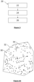
figure 3 is a flowchart of the surveillance method performed by the surveillance system offigure 1 ; and -
figures 4A to 4D are maps representing an area of interest at successive steps of the surveillance method offigure 3 . - It is well understood that the embodiments that will be described below are in no way limitative. In particular, it is possible to imagine variants of the invention comprising only a selection of the characteristics described hereinafter, in isolation from the other characteristics described, if this selection of characteristics is sufficient to confer a technical advantage or to differentiate the invention with respect to the state of the prior art. Such a selection comprises at least one, preferably functional, characteristic without structural details, or with only a part of the structural details if this part alone is sufficient to confer a technical advantage or to differentiate the invention with respect to the prior art.
- In the figures, elements common to several figures retain the same reference.
- A
surveillance system 2 according to the invention is shown onfigures 1 and 2 . - The
surveillance system 2 is configured to perform surveillance of an area of interest. More precisely, the limits of the area of interest have known geographic coordinates. - The
surveillance system 2 includes a swarm 4 of drones and acontrol unit 6 in communication with each other. - The swarm of drones 4 includes at least one
drone 8. - Each
drone 8 is an unmanned drone configured to autonomously perform surveillance of a sub-area of the area of interest to which said drone is affected. - Affectation of each
drone 8 to a corresponding sub-area will be described below. - As shown on
figure 2 , eachdrone 8 includes asurveillance module 10 and acommunication module 12. - More precisely, for each
drone 8, thesurveillance module 10 is configured to detect and track targets in the respective sub-area. For instance, thesurveillance module 10 includes an acquisition stage, a processing stage and a location stage (not shown). - The acquisition stage may be configured to acquire images of the respective sub-area. Furthermore, the processing stage may be configured to process the acquired images to detect the targets in said sub-area.
- Alternatively, or in addition, the
surveillance module 10 may be configured to acquire, for each target, a radio signal emitted by said target. For instance, said radio signal is a GPS (for "Global Positioning System") signal, an RFID (for "Radio Frequency Identification") signal, a Wi-Fi (for "Wireless Fidelity") signal and/or a cellular data signal. In this case, the processing stage is configured to process each acquired radio signal to detect the targets in the sub-area. - The location stage is configured to track each detected target in the area of interest. Preferably, the location stage is also configured to compute a position of each tracked target.
- Furthermore, the location stage is configured to compute a position of the
corresponding drone 8. - For each
drone 8, thecommunication module 12 is configured to communicate with thecontrol unit 6. - More precisely, for each
drone 8, thecorresponding communication module 12 is configured to inform thecontrol unit 6 regarding the current position of the saiddrone 8. - The
communication module 12 may also be configured to inform thecontrol unit 6 that thecorresponding drone 8 is operational. - The
communication module 12 may be further configured to inform thecontrol unit 6 regarding a current autonomy (e.g., a state of charge or a fuel reserve) of thecorresponding drone 8. Alternatively, or in addition, thecommunication module 12 may be also be configured to notify thecontrol unit 6 that thecorresponding drone 8 is returning to a corresponding docking station, for instance for recharging or refueling. - Advantageously, the
communication module 12 is also be configured to send a unique identifier of therespective drone 8 to thecontrol unit 6. This feature is advantageous, as it allows to authenticate eachdrone 8, thereby preventing invasion from an unknown source. - Preferably, the
communication module 12 of each drone is configured to communicate with thecommunication module 12 of at least one of theother drones 8 of the swarm 4. This feature allows to improve efficiency and enable collaborative decision making. For instance, if a given drone detects a suspicious event, it can alert other drones in the swarm to validate and investigate a corresponding part of the area of interest closely, while freeing up other drones to cover other parts of the area of interest. - Advantageously, for security purposes, the
communication module 12 is configured so that the communication with thecontrol unit 6 is encrypted. - Advantageously, the
communication module 12 is configured to communicate with thecontrol unit 6 using wireless D2G ("device-to-gateway") communication. This feature is advantageous, as it allows for reduced transmission failure, delay fading, and message errors. - The
control unit 6 is a hardware-based unit, such as a processor, an electronic chip, a calculator, a smartphone, a computer, a server (e.g., an on-premises server) and the like. Alternatively, or in addition, theprocessing unit 6 is a software-based unit, such as an application, a computer program (e.g., a computer program running in the cloud), a virtual machine and the like. - The
control unit 6 is configured to receive, from a user, the coordinates of the area of interest where surveillance should be performed. - The
control unit 6 is configured to provide instructions to eachdrone 8 of the swarm of drones 4 for performing surveillance. - More precisely, the
control unit 6 is configured to implement a surveillance method 20 (figure 3 ) in order to determine, in real time, and for eachdrone 8 of the swarm of drones 4, a corresponding sub-area for surveillance, and to affect eachdrone 8 to the corresponding sub-area. - As shown on
figure 3 , theprocessing method 20 comprises amonitoring step 22, asegmentation step 24 and anaffectation step 26. - The
control unit 6 is configured to, during themonitoring step 22, monitor a number N ofoperational drones 8 of the set of drones 4. - More specifically, the
control unit 6 is configured to monitor, preferably continuously, the number ofoperational drones 8 based on the data received from eachdrone 8 through thecorresponding communication module 12. - Moreover, the
control unit 6 is configured to perform thesegmentation step 24 and theaffectation step 26 if it detects a change in the number ofdrones 8 that are currently operational. - Furthermore, the
control unit 6 is configured to, during thesegmentation step 24, segment the area of interest into N sub-areas, N being the current number ofoperational drones 8. - Advantageously, the sub-areas cover the whole area of interest without overlapping. This feature is advantageous, as having two or more drones perform surveillance on a same zone would be detrimental to efficiency. Moreover, this feature ensures that surveillance covers the entire area of interest.
- Preferably, to perform such segmentation, the
control unit 6 is configured to, during thesegmentation step 24, arrange a set of virtual points in a georeferenced representation of the area of interest. - An example of such arrangement is shown on
figure 4A . In this figure, an exemplarygeoreferenced representation 30 of an area of interest is delimited by aborder 32. Furthermore, each dot 34 represents one of the aforementioned virtual points. - Advantageously, the
control unit 6 is configured to randomly arrange the virtual points in said georeferenced representation of the area of interest. This feature is advantageous, as it eventually results in sub-areas having similar surfaces without requiring an excessive computational cost. - Moreover, the
control unit 6 is preferably configured to cluster the virtual points into N clusters, based on a position of each virtual point. - In the example of figures 3A-3D, it has been assumed that the current number of
operational drones 8 is equal to 3, resulting in three clusters of virtual points. As can be seen onfigure 4B , the virtual points belonging to the first cluster are represented using a dark circle, the virtual points belonging to the second cluster are represented using a white circle, and the virtual points belonging to the third cluster are represented using a dark triangle. - Advantageously, the
control unit 6 is configured so that the N clusters each include the same number of virtual points. This feature is advantageous, as it also results in sub-areas having similar surfaces, without an excessive computational cost. - Even more advantageously, the
control unit 6 is configured to perform a k-means clustering to cluster the virtual points. In this case, the hyperparameter of the k-means clustering algorithm is the current number N ofoperational drones 8. This feature is advantageous, as such algorithm is simple and easy to implement. Such algorithm is also fast and efficient in terms of computational cost, which allows to rapidly adapt to a change in the number ofoperational drones 8. - Preferably, the
control unit 6 is configured to determine, for each cluster, the boundaries of a respective sub-area. - More precisely, each cluster is associated with a respective point of interest. In this case, a position of each point of interest depends on a position of each virtual point of the associated cluster.
- Preferably, for each cluster, the respective point of interest is a centroid of the virtual points of said cluster.
- For instance, in
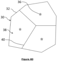
figure 4C , the centroid of each of the three clusters of virtual points is represented using awhite star 36. - Moreover, the
control unit 6 is preferably configured to determine, for each cluster, the boundaries of the respective sub-area based on the position of the corresponding point of interest. - Advantageously, the
control unit 6 is configured to generate, for each cluster, the corresponding sub-area by computing a Voronoi diagram of the area of interest. In this case, each point of interest forms a seed of the Voronoi diagram, and the boundaries of each Voronoi cell form the boundaries of a respective sub-area. Using a Voronoi diagram is advantageous as it results in sub-areas that cover the entire area of interest. Besides, Voronoi diagram also performs spatial analysis to ensure that the sub-areas are similar in size in order to balance the workload for each drone. - In the example of figures 3A-3D, and as can be seen on
figure 4D , each of the three sub-areas 38 is delimited by a corresponding border 40 (also called "boundary"). - The
control unit 6 is also configured to affect, during theaffectation step 26, eachdrone 8 that is currently operational to a respective sub-area for surveilling said sub-area. - The
control unit 6 may include additional features. - For instance, the
control unit 6 is configured to decrypt and encrypt inbound and outbound data messages to ensure that data transmission between thecontrol unit 6 and eachdrone 8 is secure. - The authentication module may also be configured to authenticate the identity of each
drone 8 to avoid invasion from an unknown source. - The
control unit 6 may also be configured to perform a pathing planning a space search algorithm to control the drone swarm 4 flying behaviors to perform specific goals like target searching. For instance, in the case where a single target is looked for, when the target is detected or found by one of the drones, the nearest drone will be alerted and will fly to the inspected sub-area for validation. Once the target is confirmed, the whole swarm will be requested to perform space search algorithm to fly back to a corresponding base station. Thus, the pathing planning and space search algorithm is included to optimize the flying path. - The
control unit 6 may also be configured to compute, for eachdrone 8, a corresponding path (e.g., a flying path) to perform surveillance of the respective sub-area. This feature allows to improve the flying distance by reducing the number of waypoints. - The
control unit 6 may also be configured to implement a collision detection and avoidance algorithm to control the drones flying in a swarm without colliding and crashing with each other. Indeed, due to the limited computation power and battery life of drone, computational task is designed to be performed at thecontrol unit 6. Meanwhile, eachdrone 8 operates as an edge device for data collection and data communication. This implementation reduces the drone computational requirement and prolongs drone's battery life. - Alternatively, the
control unit 6 is embedded in a drone of the swarm of drones, acting as a master drone. - Having the sub-areas cover the whole area of interest without overlapping is advantageous, as having two or more drones perform surveillance on a same zone would be detrimental to efficiency. Moreover, this feature ensures that surveillance covers the entire area of interest.
- Randomly arranging the virtual points in the georeferenced representation of the area of interest is advantageous, as this feature eventually results in sub-areas having similar surfaces without requiring an excessive computational cost.
- Having the N clusters include the same number of virtual points is advantageous, as this feature also results in sub-areas having similar surfaces, without an excessive computational cost.
- Performing a k-means clustering algorithm to cluster the virtual points is advantageous, as such algorithm is simple and easy to implement. Such algorithm is also fast and efficient in terms of computational cost, which allows to rapidly adapt to a change in the number of
operational drones 8. - Using a Voronoi diagram to generate the sub-area is also advantageous, as it results in sub-areas that cover the entire area of interest. Besides, Voronoi diagram also performs spatial analysis to ensure that the sub-areas are similar in size in order to balance the workload for each drone.
- Operation of the
surveillance system 2 will now be described with reference tofigure 2 . - During the
monitoring step 22, thecontrol unit 6 monitors, preferably continuously, the number N ofoperational drones 8 of the set of drones 4. - If the
control unit 6 detects a change in the number ofdrones 8 that are currently operational, then, thecontrol unit 6 performs thesegmentation step 24. - More precisely, during the
segmentation step 24, thecontrol unit 6 segments the area of interest into N sub-areas, N being the current number ofoperational drones 8. - For instance, to perform such segmentation, the
control unit 6 randomly arranges a set of virtual points in a georeferenced representation of the area of interest. Then, thecontrol unit 6 clusters the virtual points into N clusters, based on a position of each virtual point, preferably using a k-means clustering algorithm. Then, for each cluster, thecontrol unit 6 determines the boundaries of a respective sub-area, preferably by computing a Voronoi diagram of the area of interest, with the centroid of each cluster forming a seed of the Voronoi diagram, and the boundaries of each Voronoi cell forming the boundaries of a respective sub-area. - Then, during the
affectation step 26, thecontrol unit 6 affects eachdrone 8 that is currently operational to a respective determined sub-area for surveilling said sub-area. - Of course, the invention is not limited to the examples detailed above.
Claims (15)
- A computer-implemented surveillance method for surveying an area of interest using a set of drones, the surveillance method comprising monitoring a number of operational drones among the set of drones, and, if a change in the number of operational drones is detected, performing:- a segmentation step for segmenting the area of interest into N sub-areas, N being the current number of operational drones; and- an affectation step for affecting each operational drone to a respective sub-area for surveilling said sub-area.
- The method according to claim 1, wherein the sub-areas cover the whole area of interest without overlapping.
- The method according to claim 1 or 2, wherein the segmentation step includes:- arranging a set of virtual points in a georeferenced representation of the area of interest;- clustering the virtual points into N clusters based on a position of each virtual point, each cluster being associated with a respective point of interest, a position of each point of interest depending on a position of each virtual point of the associated cluster; and- for each cluster, determining boundaries of a corresponding sub-area based on a position of the corresponding point of interest.
- The method according to claim 3, wherein, during the segmentation step, the virtual points are arranged randomly in the georeferenced representation of the area of interest.
- The method according to claim 3 or 4, wherein the N clusters each include the same number of virtual points.
- The method according to any one of claims 3 to 5, wherein clustering the virtual points into N clusters includes performing a k-means clustering.
- The method according to any one of claims 3 to 6, wherein, for each cluster, the respective point of interest is a centroid of the virtual points of said cluster.
- The method according to any one of claims 3 to 7, wherein, for each cluster, generating the corresponding sub-area includes computing a Voronoi diagram of the area of interest, each point of interest forming a seed of the Voronoi diagram, and the boundaries of each Voronoi cell forming the boundaries of a respective sub-area.
- Computer program comprising instructions, which when executed by a computer, cause the computer to carry out the steps of the method according to any one of claims 1 to 8.
- A surveillance system (2) including a control unit (6) and a set (4) of drones (8) for performing surveillance of an area of interest, the control unit (6) being configured to monitor a number of operational drones (8) among the set of drones (4), the control unit (6) being further configured, if a change in the number of operational drones (8) is detected, to:- segment the area of interest into N sub-areas (38), N being the current number of operational drones (8); and- affect each operational drone (8) to a respective sub-area for surveilling said sub-area.
- The surveillance system (2) according to claim 10, wherein, in order to segment the area of interest into N sub-areas (38), the control unit (6) is configured to:- arrange a set of virtual points (34) in a georeferenced representation (30) of the area of interest;- cluster the virtual points (34) into N clusters based on a position of each virtual point (34), each cluster being associated with a respective point of interest (36), a position of each point of interest (36) depending on a position of each virtual point (34) of the associated cluster; and- for each cluster, determine boundaries (40) of a corresponding sub-area (38) based on a position of the corresponding point of interest (36),and, preferably, for each cluster, the respective point of interest (36) being a centroid of the virtual points (34) of said cluster.
- The surveillance system (2) according to claim 11, wherein the control unit (6) is configured to randomly arrange the virtual points (34) in the georeferenced representation (30) of the area of interest.
- The surveillance system (2) according to claim 11 or 12, wherein the N clusters each include the same number of virtual points.
- The surveillance system (2) according to any one of claims 11 to 13, wherein the processing unit (6) is configured to perform a k-means clustering to cluster the virtual points into N clusters.
- The surveillance system (2) according to any one of claims 11 to 14, wherein, in order to generate the sub-area corresponding to each cluster, the processing unit (6) is configured to compute a Voronoi diagram of the area of interest, each point of interest (36) forming a seed of the Voronoi diagram, and the boundaries of each Voronoi cell forming the boundaries (40) of a respective sub-area.
Priority Applications (2)
| Application Number | Priority Date | Filing Date | Title |
|---|---|---|---|
| EP23305358.6A EP4432038B1 (en) | 2023-03-16 | 2023-03-16 | Method for surveilling an area of interest using drones |
| US18/605,189 US20240312215A1 (en) | 2023-03-16 | 2024-03-14 | Method for surveilling an area of interest using drones |
Applications Claiming Priority (1)
| Application Number | Priority Date | Filing Date | Title |
|---|---|---|---|
| EP23305358.6A EP4432038B1 (en) | 2023-03-16 | 2023-03-16 | Method for surveilling an area of interest using drones |
Publications (2)
| Publication Number | Publication Date |
|---|---|
| EP4432038A1 true EP4432038A1 (en) | 2024-09-18 |
| EP4432038B1 EP4432038B1 (en) | 2025-11-26 |
Family
ID=86731931
Family Applications (1)
| Application Number | Title | Priority Date | Filing Date |
|---|---|---|---|
| EP23305358.6A Active EP4432038B1 (en) | 2023-03-16 | 2023-03-16 | Method for surveilling an area of interest using drones |
Country Status (2)
| Country | Link |
|---|---|
| US (1) | US20240312215A1 (en) |
| EP (1) | EP4432038B1 (en) |
Cited By (1)
| Publication number | Priority date | Publication date | Assignee | Title |
|---|---|---|---|---|
| CN120631055A (en) * | 2025-08-12 | 2025-09-12 | 中国人民解放军国防科技大学 | A vision-enhanced multi-UAV embodied search system |
Families Citing this family (1)
| Publication number | Priority date | Publication date | Assignee | Title |
|---|---|---|---|---|
| CN117892954B (en) * | 2024-01-12 | 2024-08-16 | 山东大学 | Adaptive role selection method and system for multi-robot collaborative search tasks |
Citations (1)
| Publication number | Priority date | Publication date | Assignee | Title |
|---|---|---|---|---|
| EP2688016A1 (en) * | 2012-07-18 | 2014-01-22 | The Boeing Company | Mission re-planning for coordinated multivehicle |
Family Cites Families (3)
| Publication number | Priority date | Publication date | Assignee | Title |
|---|---|---|---|---|
| PL3293115T3 (en) * | 2016-09-07 | 2020-04-30 | Siemens Aktiengesellschaft | Method for controlling of unmanned aerial vehicles |
| US20190011920A1 (en) * | 2017-07-07 | 2019-01-10 | Sharper Shape Oy | Method and system for generating flight plan of unmanned aerial vehicle for aerial inspection |
| WO2021087750A1 (en) * | 2019-11-05 | 2021-05-14 | 深圳市大疆创新科技有限公司 | Route planning method and device for unmanned aerial vehicle |
-
2023
- 2023-03-16 EP EP23305358.6A patent/EP4432038B1/en active Active
-
2024
- 2024-03-14 US US18/605,189 patent/US20240312215A1/en active Pending
Patent Citations (1)
| Publication number | Priority date | Publication date | Assignee | Title |
|---|---|---|---|---|
| EP2688016A1 (en) * | 2012-07-18 | 2014-01-22 | The Boeing Company | Mission re-planning for coordinated multivehicle |
Non-Patent Citations (1)
| Title |
|---|
| BOURAS ABDELWAHHAB ET AL: "Areas Division and Multiple UAV Coverage Path Planning For Gas Distribution Map", 2022 19TH INTERNATIONAL MULTI-CONFERENCE ON SYSTEMS, SIGNALS & DEVICES (SSD), IEEE, 6 May 2022 (2022-05-06), pages 1554 - 1560, XP034235271, DOI: 10.1109/SSD54932.2022.9955697 * |
Cited By (1)
| Publication number | Priority date | Publication date | Assignee | Title |
|---|---|---|---|---|
| CN120631055A (en) * | 2025-08-12 | 2025-09-12 | 中国人民解放军国防科技大学 | A vision-enhanced multi-UAV embodied search system |
Also Published As
| Publication number | Publication date |
|---|---|
| US20240312215A1 (en) | 2024-09-19 |
| EP4432038B1 (en) | 2025-11-26 |
Similar Documents
| Publication | Publication Date | Title |
|---|---|---|
| US20240312215A1 (en) | Method for surveilling an area of interest using drones | |
| Dang et al. | Deep-ensemble-learning-based GPS spoofing detection for cellular-connected UAVs | |
| US10466700B1 (en) | Detecting of navigation data spoofing based on signal strength variance | |
| US11050481B2 (en) | Systems and methods for creating wireless aerial traffic corridors | |
| US9524648B1 (en) | Countermeasures for threats to an uncrewed autonomous vehicle | |
| US9847033B1 (en) | Communication of navigation data spoofing between unmanned vehicles | |
| US9849978B1 (en) | Detecting of navigation data spoofing based on sensor data | |
| US10325169B2 (en) | Spatio-temporal awareness engine for priority tree based region selection across multiple input cameras and multimodal sensor empowered awareness engine for target recovery and object path prediction | |
| US20210025975A1 (en) | Systems, methods, apparatuses, and devices for radar-based identifying, tracking, and managing of unmanned aerial vehicles | |
| KR101695547B1 (en) | Method and apparatus for detecting unmanned aerial vehicles using leakage signal of global positioning system | |
| US10007265B1 (en) | Hostile takeover avoidance of unmanned vehicles | |
| CN111181627A (en) | Target detection system | |
| CN112947580A (en) | Fusion processing method, device, system, equipment and medium for unmanned aerial vehicle positioning | |
| US20250232467A1 (en) | Computer vision classifier defined path planning for unmanned aerial vehicles | |
| Grushchak et al. | Decentralized multi-drone coordination for wildlife video acquisition | |
| KR20240007151A (en) | Processing of information relating to one or more monitored areas | |
| US20260046830A1 (en) | Determining a location of a connected edge device in real-time using cellular ran, core and edge information | |
| Posch et al. | UAV based search for a radio tagged animal using particle filters | |
| CN116419162A (en) | Non-networked UAV tracking and monitoring method and system based on new generation core network | |
| US12536917B2 (en) | Tracking a moving entity | |
| CN118550319A (en) | A UAV tracking method based on multi-fusion data | |
| JP2024039358A (en) | Abnormality analysis method, abnormality analysis device, and abnormality analysis program | |
| US20230043836A1 (en) | Information processing apparatus, information processing method, and program | |
| CN113867416A (en) | Processing method, system and device for unmanned aerial vehicle detection | |
| US9994289B2 (en) | Automated commercial fishing location determination |
Legal Events
| Date | Code | Title | Description |
|---|---|---|---|
| PUAI | Public reference made under article 153(3) epc to a published international application that has entered the european phase |
Free format text: ORIGINAL CODE: 0009012 |
|
| STAA | Information on the status of an ep patent application or granted ep patent |
Free format text: STATUS: THE APPLICATION HAS BEEN PUBLISHED |
|
| AK | Designated contracting states |
Kind code of ref document: A1 Designated state(s): AL AT BE BG CH CY CZ DE DK EE ES FI FR GB GR HR HU IE IS IT LI LT LU LV MC ME MK MT NL NO PL PT RO RS SE SI SK SM TR |
|
| STAA | Information on the status of an ep patent application or granted ep patent |
Free format text: STATUS: REQUEST FOR EXAMINATION WAS MADE |
|
| 17P | Request for examination filed |
Effective date: 20250303 |
|
| STAA | Information on the status of an ep patent application or granted ep patent |
Free format text: STATUS: EXAMINATION IS IN PROGRESS |
|
| 17Q | First examination report despatched |
Effective date: 20250424 |
|
| P01 | Opt-out of the competence of the unified patent court (upc) registered |
Free format text: CASE NUMBER: APP_22859/2025 Effective date: 20250514 |
|
| REG | Reference to a national code |
Ref country code: DE Ref legal event code: R079 Free format text: PREVIOUS MAIN CLASS: G05D0001020000 Ipc: G05D0001248000 Ref document number: 602023009005 Country of ref document: DE |
|
| GRAP | Despatch of communication of intention to grant a patent |
Free format text: ORIGINAL CODE: EPIDOSNIGR1 |
|
| STAA | Information on the status of an ep patent application or granted ep patent |
Free format text: STATUS: GRANT OF PATENT IS INTENDED |
|
| INTG | Intention to grant announced |
Effective date: 20250701 |
|
| RIC1 | Information provided on ipc code assigned before grant |
Ipc: G05D 1/248 20240101AFI20250620BHEP Ipc: G05D 1/43 20240101ALI20250620BHEP Ipc: G05D 105/85 20240101ALI20250620BHEP Ipc: G05D 109/25 20240101ALI20250620BHEP Ipc: G08G 5/21 20250101ALI20250620BHEP Ipc: G08G 5/25 20250101ALI20250620BHEP Ipc: G08G 5/26 20250101ALI20250620BHEP Ipc: G08G 5/53 20250101ALI20250620BHEP Ipc: G08G 5/55 20250101ALI20250620BHEP Ipc: G08G 5/72 20250101ALI20250620BHEP Ipc: G05D 1/648 20240101ALI20250620BHEP Ipc: G05D 1/698 20240101ALI20250620BHEP |
|
| GRAS | Grant fee paid |
Free format text: ORIGINAL CODE: EPIDOSNIGR3 |
|
| GRAA | (expected) grant |
Free format text: ORIGINAL CODE: 0009210 |
|
| STAA | Information on the status of an ep patent application or granted ep patent |
Free format text: STATUS: THE PATENT HAS BEEN GRANTED |
|
| AK | Designated contracting states |
Kind code of ref document: B1 Designated state(s): AL AT BE BG CH CY CZ DE DK EE ES FI FR GB GR HR HU IE IS IT LI LT LU LV MC ME MK MT NL NO PL PT RO RS SE SI SK SM TR |
|
| REG | Reference to a national code |
Ref country code: CH Ref legal event code: F10 Free format text: ST27 STATUS EVENT CODE: U-0-0-F10-F00 (AS PROVIDED BY THE NATIONAL OFFICE) Effective date: 20251126 Ref country code: GB Ref legal event code: FG4D |
|
| REG | Reference to a national code |
Ref country code: IE Ref legal event code: FG4D |
|
| REG | Reference to a national code |
Ref country code: DE Ref legal event code: R096 Ref document number: 602023009005 Country of ref document: DE |
|
| REG | Reference to a national code |
Ref country code: NL Ref legal event code: MP Effective date: 20251126 |
|
| PG25 | Lapsed in a contracting state [announced via postgrant information from national office to epo] |
Ref country code: ES Free format text: LAPSE BECAUSE OF FAILURE TO SUBMIT A TRANSLATION OF THE DESCRIPTION OR TO PAY THE FEE WITHIN THE PRESCRIBED TIME-LIMIT Effective date: 20251126 |
|
| REG | Reference to a national code |
Ref country code: LT Ref legal event code: MG9D |
|
| PG25 | Lapsed in a contracting state [announced via postgrant information from national office to epo] |
Ref country code: NO Free format text: LAPSE BECAUSE OF FAILURE TO SUBMIT A TRANSLATION OF THE DESCRIPTION OR TO PAY THE FEE WITHIN THE PRESCRIBED TIME-LIMIT Effective date: 20260226 |
|
| PGFP | Annual fee paid to national office [announced via postgrant information from national office to epo] |
Ref country code: DE Payment date: 20260320 Year of fee payment: 4 |
|
| PG25 | Lapsed in a contracting state [announced via postgrant information from national office to epo] |
Ref country code: AT Free format text: LAPSE BECAUSE OF FAILURE TO SUBMIT A TRANSLATION OF THE DESCRIPTION OR TO PAY THE FEE WITHIN THE PRESCRIBED TIME-LIMIT Effective date: 20251126 Ref country code: HR Free format text: LAPSE BECAUSE OF FAILURE TO SUBMIT A TRANSLATION OF THE DESCRIPTION OR TO PAY THE FEE WITHIN THE PRESCRIBED TIME-LIMIT Effective date: 20251126 Ref country code: FI Free format text: LAPSE BECAUSE OF FAILURE TO SUBMIT A TRANSLATION OF THE DESCRIPTION OR TO PAY THE FEE WITHIN THE PRESCRIBED TIME-LIMIT Effective date: 20251126 |
|
| PGFP | Annual fee paid to national office [announced via postgrant information from national office to epo] |
Ref country code: AT Payment date: 20260301 Year of fee payment: 4 |
|
| REG | Reference to a national code |
Ref country code: AT Ref legal event code: MK05 Ref document number: 1861674 Country of ref document: AT Kind code of ref document: T Effective date: 20251126 |
|
| PG25 | Lapsed in a contracting state [announced via postgrant information from national office to epo] |
Ref country code: NL Free format text: LAPSE BECAUSE OF FAILURE TO SUBMIT A TRANSLATION OF THE DESCRIPTION OR TO PAY THE FEE WITHIN THE PRESCRIBED TIME-LIMIT Effective date: 20251126 |
|
| PG25 | Lapsed in a contracting state [announced via postgrant information from national office to epo] |
Ref country code: RS Free format text: LAPSE BECAUSE OF FAILURE TO SUBMIT A TRANSLATION OF THE DESCRIPTION OR TO PAY THE FEE WITHIN THE PRESCRIBED TIME-LIMIT Effective date: 20260226 |
|
| PG25 | Lapsed in a contracting state [announced via postgrant information from national office to epo] |
Ref country code: IS Free format text: LAPSE BECAUSE OF FAILURE TO SUBMIT A TRANSLATION OF THE DESCRIPTION OR TO PAY THE FEE WITHIN THE PRESCRIBED TIME-LIMIT Effective date: 20260326 |
|
| PGFP | Annual fee paid to national office [announced via postgrant information from national office to epo] |
Ref country code: FR Payment date: 20260324 Year of fee payment: 4 |
|
| PG25 | Lapsed in a contracting state [announced via postgrant information from national office to epo] |
Ref country code: PT Free format text: LAPSE BECAUSE OF FAILURE TO SUBMIT A TRANSLATION OF THE DESCRIPTION OR TO PAY THE FEE WITHIN THE PRESCRIBED TIME-LIMIT Effective date: 20260326 |
|
| PG25 | Lapsed in a contracting state [announced via postgrant information from national office to epo] |
Ref country code: PL Free format text: LAPSE BECAUSE OF FAILURE TO SUBMIT A TRANSLATION OF THE DESCRIPTION OR TO PAY THE FEE WITHIN THE PRESCRIBED TIME-LIMIT Effective date: 20251126 |
|
| PG25 | Lapsed in a contracting state [announced via postgrant information from national office to epo] |
Ref country code: LV Free format text: LAPSE BECAUSE OF FAILURE TO SUBMIT A TRANSLATION OF THE DESCRIPTION OR TO PAY THE FEE WITHIN THE PRESCRIBED TIME-LIMIT Effective date: 20251126 |
|
| PG25 | Lapsed in a contracting state [announced via postgrant information from national office to epo] |
Ref country code: BG Free format text: LAPSE BECAUSE OF FAILURE TO SUBMIT A TRANSLATION OF THE DESCRIPTION OR TO PAY THE FEE WITHIN THE PRESCRIBED TIME-LIMIT Effective date: 20251126 |