EP4432015A1 - Fixing device and image forming apparatus - Google Patents
Fixing device and image forming apparatus Download PDFInfo
- Publication number
- EP4432015A1 EP4432015A1 EP24162881.7A EP24162881A EP4432015A1 EP 4432015 A1 EP4432015 A1 EP 4432015A1 EP 24162881 A EP24162881 A EP 24162881A EP 4432015 A1 EP4432015 A1 EP 4432015A1
- Authority
- EP
- European Patent Office
- Prior art keywords
- fixing
- fixing device
- side plates
- plate
- heater
- Prior art date
- Legal status (The legal status is an assumption and is not a legal conclusion. Google has not performed a legal analysis and makes no representation as to the accuracy of the status listed.)
- Pending
Links
- 238000000926 separation method Methods 0.000 claims abstract description 156
- 238000003780 insertion Methods 0.000 claims description 48
- 230000037431 insertion Effects 0.000 claims description 48
- 238000009434 installation Methods 0.000 claims description 48
- 229910052751 metal Inorganic materials 0.000 claims description 5
- 239000002184 metal Substances 0.000 claims description 5
- 238000010438 heat treatment Methods 0.000 description 76
- 238000012546 transfer Methods 0.000 description 54
- 239000010410 layer Substances 0.000 description 43
- OKTJSMMVPCPJKN-UHFFFAOYSA-N Carbon Chemical compound [C] OKTJSMMVPCPJKN-UHFFFAOYSA-N 0.000 description 29
- 229910002804 graphite Inorganic materials 0.000 description 15
- 239000010439 graphite Substances 0.000 description 15
- 229910021389 graphene Inorganic materials 0.000 description 13
- 238000010586 diagram Methods 0.000 description 12
- 230000015572 biosynthetic process Effects 0.000 description 9
- 125000004432 carbon atom Chemical group C* 0.000 description 9
- 230000020169 heat generation Effects 0.000 description 9
- 238000009413 insulation Methods 0.000 description 9
- 238000000034 method Methods 0.000 description 8
- XEEYBQQBJWHFJM-UHFFFAOYSA-N Iron Chemical group [Fe] XEEYBQQBJWHFJM-UHFFFAOYSA-N 0.000 description 7
- 239000004642 Polyimide Substances 0.000 description 7
- 229920001721 polyimide Polymers 0.000 description 7
- 230000005540 biological transmission Effects 0.000 description 6
- 230000000052 comparative effect Effects 0.000 description 6
- 239000000470 constituent Substances 0.000 description 6
- 238000007639 printing Methods 0.000 description 6
- 239000013078 crystal Substances 0.000 description 5
- 230000007423 decrease Effects 0.000 description 5
- 229920000106 Liquid crystal polymer Polymers 0.000 description 4
- 239000004977 Liquid-crystal polymers (LCPs) Substances 0.000 description 4
- 238000004140 cleaning Methods 0.000 description 4
- 230000000694 effects Effects 0.000 description 4
- 238000011144 upstream manufacturing Methods 0.000 description 4
- PXHVJJICTQNCMI-UHFFFAOYSA-N Nickel Chemical compound [Ni] PXHVJJICTQNCMI-UHFFFAOYSA-N 0.000 description 3
- 239000004696 Poly ether ether ketone Substances 0.000 description 3
- -1 and prepreg Substances 0.000 description 3
- 239000011521 glass Substances 0.000 description 3
- 229910052742 iron Inorganic materials 0.000 description 3
- 239000000463 material Substances 0.000 description 3
- 229920002530 polyetherether ketone Polymers 0.000 description 3
- 229920001343 polytetrafluoroethylene Polymers 0.000 description 3
- 239000004810 polytetrafluoroethylene Substances 0.000 description 3
- 230000008569 process Effects 0.000 description 3
- 239000002356 single layer Substances 0.000 description 3
- 229910001220 stainless steel Inorganic materials 0.000 description 3
- 239000010935 stainless steel Substances 0.000 description 3
- XMWRBQBLMFGWIX-UHFFFAOYSA-N C60 fullerene Chemical group C12=C3C(C4=C56)=C7C8=C5C5=C9C%10=C6C6=C4C1=C1C4=C6C6=C%10C%10=C9C9=C%11C5=C8C5=C8C7=C3C3=C7C2=C1C1=C2C4=C6C4=C%10C6=C9C9=C%11C5=C5C8=C3C3=C7C1=C1C2=C4C6=C2C9=C5C3=C12 XMWRBQBLMFGWIX-UHFFFAOYSA-N 0.000 description 2
- RYGMFSIKBFXOCR-UHFFFAOYSA-N Copper Chemical compound [Cu] RYGMFSIKBFXOCR-UHFFFAOYSA-N 0.000 description 2
- 230000002411 adverse Effects 0.000 description 2
- 229910052782 aluminium Inorganic materials 0.000 description 2
- XAGFODPZIPBFFR-UHFFFAOYSA-N aluminium Chemical compound [Al] XAGFODPZIPBFFR-UHFFFAOYSA-N 0.000 description 2
- 239000000919 ceramic Substances 0.000 description 2
- 238000005229 chemical vapour deposition Methods 0.000 description 2
- 239000004020 conductor Substances 0.000 description 2
- 229920006015 heat resistant resin Polymers 0.000 description 2
- 239000003779 heat-resistant material Substances 0.000 description 2
- 239000007769 metal material Substances 0.000 description 2
- 238000013021 overheating Methods 0.000 description 2
- 230000002093 peripheral effect Effects 0.000 description 2
- 239000000843 powder Substances 0.000 description 2
- 230000009467 reduction Effects 0.000 description 2
- 230000004044 response Effects 0.000 description 2
- 239000007787 solid Substances 0.000 description 2
- 241000024287 Areas Species 0.000 description 1
- BQCADISMDOOEFD-UHFFFAOYSA-N Silver Chemical compound [Ag] BQCADISMDOOEFD-UHFFFAOYSA-N 0.000 description 1
- 229910000831 Steel Inorganic materials 0.000 description 1
- 238000007792 addition Methods 0.000 description 1
- PNEYBMLMFCGWSK-UHFFFAOYSA-N aluminium oxide Inorganic materials [O-2].[O-2].[O-2].[Al+3].[Al+3] PNEYBMLMFCGWSK-UHFFFAOYSA-N 0.000 description 1
- 229910052799 carbon Inorganic materials 0.000 description 1
- 239000011248 coating agent Substances 0.000 description 1
- 238000000576 coating method Methods 0.000 description 1
- 239000003086 colorant Substances 0.000 description 1
- 150000001875 compounds Chemical class 0.000 description 1
- 238000010276 construction Methods 0.000 description 1
- 229920001577 copolymer Polymers 0.000 description 1
- 229910052802 copper Inorganic materials 0.000 description 1
- 239000010949 copper Substances 0.000 description 1
- 239000011889 copper foil Substances 0.000 description 1
- PMHQVHHXPFUNSP-UHFFFAOYSA-M copper(1+);methylsulfanylmethane;bromide Chemical compound Br[Cu].CSC PMHQVHHXPFUNSP-UHFFFAOYSA-M 0.000 description 1
- 230000007547 defect Effects 0.000 description 1
- 238000012217 deletion Methods 0.000 description 1
- 230000037430 deletion Effects 0.000 description 1
- 238000001514 detection method Methods 0.000 description 1
- 238000006073 displacement reaction Methods 0.000 description 1
- 238000009826 distribution Methods 0.000 description 1
- 229920001971 elastomer Polymers 0.000 description 1
- 238000005265 energy consumption Methods 0.000 description 1
- 238000010304 firing Methods 0.000 description 1
- 229910003472 fullerene Inorganic materials 0.000 description 1
- 239000012535 impurity Substances 0.000 description 1
- 239000011810 insulating material Substances 0.000 description 1
- 239000012212 insulator Substances 0.000 description 1
- 239000010445 mica Substances 0.000 description 1
- 229910052618 mica group Inorganic materials 0.000 description 1
- 238000012986 modification Methods 0.000 description 1
- 230000004048 modification Effects 0.000 description 1
- 230000003472 neutralizing effect Effects 0.000 description 1
- 229910052759 nickel Inorganic materials 0.000 description 1
- SWELZOZIOHGSPA-UHFFFAOYSA-N palladium silver Chemical compound [Pd].[Ag] SWELZOZIOHGSPA-UHFFFAOYSA-N 0.000 description 1
- 230000000704 physical effect Effects 0.000 description 1
- 239000002985 plastic film Substances 0.000 description 1
- 229920006255 plastic film Polymers 0.000 description 1
- 125000003367 polycyclic group Chemical group 0.000 description 1
- 238000003825 pressing Methods 0.000 description 1
- 230000002787 reinforcement Effects 0.000 description 1
- 229920005989 resin Polymers 0.000 description 1
- 239000011347 resin Substances 0.000 description 1
- 238000007650 screen-printing Methods 0.000 description 1
- 229920002379 silicone rubber Polymers 0.000 description 1
- 239000004945 silicone rubber Substances 0.000 description 1
- 229910052709 silver Inorganic materials 0.000 description 1
- 239000004332 silver Substances 0.000 description 1
- 238000005549 size reduction Methods 0.000 description 1
- 230000006641 stabilisation Effects 0.000 description 1
- 238000011105 stabilization Methods 0.000 description 1
- 230000000087 stabilizing effect Effects 0.000 description 1
- 239000010959 steel Substances 0.000 description 1
- 239000000126 substance Substances 0.000 description 1
- 239000002344 surface layer Substances 0.000 description 1
- 239000013585 weight reducing agent Substances 0.000 description 1
Images
Classifications
-
- G—PHYSICS
- G03—PHOTOGRAPHY; CINEMATOGRAPHY; ANALOGOUS TECHNIQUES USING WAVES OTHER THAN OPTICAL WAVES; ELECTROGRAPHY; HOLOGRAPHY
- G03G—ELECTROGRAPHY; ELECTROPHOTOGRAPHY; MAGNETOGRAPHY
- G03G15/00—Apparatus for electrographic processes using a charge pattern
- G03G15/20—Apparatus for electrographic processes using a charge pattern for fixing, e.g. by using heat
- G03G15/2003—Apparatus for electrographic processes using a charge pattern for fixing, e.g. by using heat using heat
- G03G15/2014—Apparatus for electrographic processes using a charge pattern for fixing, e.g. by using heat using heat using contact heat
- G03G15/2017—Structural details of the fixing unit in general, e.g. cooling means, heat shielding means
- G03G15/2028—Structural details of the fixing unit in general, e.g. cooling means, heat shielding means with means for handling the copy material in the fixing nip, e.g. introduction guides, stripping means
-
- G—PHYSICS
- G03—PHOTOGRAPHY; CINEMATOGRAPHY; ANALOGOUS TECHNIQUES USING WAVES OTHER THAN OPTICAL WAVES; ELECTROGRAPHY; HOLOGRAPHY
- G03G—ELECTROGRAPHY; ELECTROPHOTOGRAPHY; MAGNETOGRAPHY
- G03G15/00—Apparatus for electrographic processes using a charge pattern
- G03G15/20—Apparatus for electrographic processes using a charge pattern for fixing, e.g. by using heat
- G03G15/2003—Apparatus for electrographic processes using a charge pattern for fixing, e.g. by using heat using heat
- G03G15/2014—Apparatus for electrographic processes using a charge pattern for fixing, e.g. by using heat using heat using contact heat
- G03G15/2053—Structural details of heat elements, e.g. structure of roller or belt, eddy current, induction heating
-
- G—PHYSICS
- G03—PHOTOGRAPHY; CINEMATOGRAPHY; ANALOGOUS TECHNIQUES USING WAVES OTHER THAN OPTICAL WAVES; ELECTROGRAPHY; HOLOGRAPHY
- G03G—ELECTROGRAPHY; ELECTROPHOTOGRAPHY; MAGNETOGRAPHY
- G03G21/00—Arrangements not provided for by groups G03G13/00 - G03G19/00, e.g. cleaning, elimination of residual charge
- G03G21/16—Mechanical means for facilitating the maintenance of the apparatus, e.g. modular arrangements
- G03G21/1604—Arrangement or disposition of the entire apparatus
- G03G21/1619—Frame structures
-
- G—PHYSICS
- G03—PHOTOGRAPHY; CINEMATOGRAPHY; ANALOGOUS TECHNIQUES USING WAVES OTHER THAN OPTICAL WAVES; ELECTROGRAPHY; HOLOGRAPHY
- G03G—ELECTROGRAPHY; ELECTROPHOTOGRAPHY; MAGNETOGRAPHY
- G03G21/00—Arrangements not provided for by groups G03G13/00 - G03G19/00, e.g. cleaning, elimination of residual charge
- G03G21/16—Mechanical means for facilitating the maintenance of the apparatus, e.g. modular arrangements
- G03G21/1642—Mechanical means for facilitating the maintenance of the apparatus, e.g. modular arrangements for connecting the different parts of the apparatus
- G03G21/1647—Mechanical connection means
-
- G—PHYSICS
- G03—PHOTOGRAPHY; CINEMATOGRAPHY; ANALOGOUS TECHNIQUES USING WAVES OTHER THAN OPTICAL WAVES; ELECTROGRAPHY; HOLOGRAPHY
- G03G—ELECTROGRAPHY; ELECTROPHOTOGRAPHY; MAGNETOGRAPHY
- G03G21/00—Arrangements not provided for by groups G03G13/00 - G03G19/00, e.g. cleaning, elimination of residual charge
- G03G21/16—Mechanical means for facilitating the maintenance of the apparatus, e.g. modular arrangements
- G03G21/1661—Mechanical means for facilitating the maintenance of the apparatus, e.g. modular arrangements means for handling parts of the apparatus in the apparatus
- G03G21/1685—Mechanical means for facilitating the maintenance of the apparatus, e.g. modular arrangements means for handling parts of the apparatus in the apparatus for the fixing unit
Definitions
- Embodiments of the present disclosure generally relate to a fixing device and an image forming apparatus incorporating the fixing device.
- images are formed by image forming processes such as electrophotographic recording, electrostatic recording, and magnetic recording, and unfixed toner images are formed on recording media (e.g., sheets) by an image transfer method or a direct method.
- a fixing device for fixing an unfixed toner image one is known that includes a heating means and heats and pressurizes a toner image formed on a recording medium in a nip between a fixing member and a pressure roller to perform a fixing process.
- a thin belt member (fixing belt) having a low heat capacity is used as a fixing member from the viewpoint of energy saving, and for example.
- a configuration is known in which a nip is formed between a heating body disposed inside the loop of the fixing belt and a pressure roller with the fixing belt interposed therebetween.
- a fixing device In a fixing device, the stability of a housing frame and the positional accuracy of constituent members are required. However, in a fixing device including a heating means, the positioning accuracy between constituent members may decrease due to, for example, differences in thermal expansion coefficients of the constituent members.
- Japanese Unexamined Patent Application Publication No. 2020-52345 discloses a configuration that includes a first positioning portion for positioning a heating member and a holding member in a longitudinal direction of the heating member, a second positioning portion for positioning the holding member and an apparatus frame in the longitudinal direction of the heating member, and a third positioning portion for positioning the apparatus frame and an image forming apparatus body in the longitudinal direction of the heating member.
- the first positioning portion and the second positioning portion or the first positioning portion and the third positioning portion are disposed on the same side with respect to a central portion of a heat generation portion in the longitudinal direction of the heating member.
- the fixing device includes, as its housing frame, a first frame including a pair of side wall portions and a front wall portion and a second frame including a rear wall portion, there are problems such as an increase in the size of the apparatus, an increase in the weight of the apparatus, and an increase in the cost of components.
- an object of the present invention is to provide a fixing device in which a housing frame can be stabilized without increasing device weight and cost.
- a fixing device to be attached to an image forming apparatus includes a housing frame, a rotatable endless fixing belt, a heater to heat the fixing belt, a heater holder to hold the heater, a stay disposed inside the fixing belt to support the heater holder, a pressure roller to form a nip between the fixing belt and the pressure roller, a guide plate to guide a recording medium to the nip, and a separation plate to separate the recording medium that has passed through the nip from the fixing belt.
- the housing frame includes a support plate disposed on a same side as the pressure roller with respect to the nip in a direction intersecting a longitudinal direction of the support plate and a pair of side plates disposed on both ends of the support plate in the longitudinal direction.
- the pair of side plates are attached to at least one of the separation plate, the guide plate, and the stay, on a same side as the fixing belt with respect to the nip in the direction intersecting the longitudinal direction.
- a fixing device can be provided that allows a housing frame to be stabilized without increasing device weight and cost.
- FIG. 1 is a schematic cross-sectional view of an image forming apparatus 100 according to an embodiment of the present disclosure.
- image forming apparatus includes a printer, a copier, a facsimile machine, or a multifunction peripheral having at least two of printing, copying, scanning, and facsimile functions.
- image formation includes the formation of images with meanings such as characters and figures and the formation of images with no meanings such as patterns.
- the image forming apparatus 100 illustrated in FIG. 1 includes four image forming units 1Y, 1M, 1C, and 1Bk detachably attached to an apparatus body thereof.
- the image forming units 1Y, 1M, 1C, and 1Bk have substantially the same configuration except for containing different color developers, i.e., yellow (Y), magenta (M), cyan (C), and black (Bk) toners, respectively.
- the colors of the developers correspond to color separation components of full-color images.
- Each of the image forming units 1Y, 1M, 1C, and 1Bk includes a drum-shaped photoconductor 2 as an image bearer, a charging device 3, a developing device 4, and a cleaning device 5.
- the charging device 3 charges the surface of the photoconductor 2.
- the developing device 4 supplies toner as the developer to the surface of the photoconductor 2 to form a toner image.
- the cleaning device 5 cleans the surface of the photoconductor 2.
- the image forming apparatus 100 includes an exposure device 6, a sheet feeding device 7, a transfer device 8, a fixing device 9 as a heating device, and a sheet ejection device 10.
- the exposure device 6 exposes the surface of the photoconductor 2 to form an electrostatic latent image on the surface of the photoconductor 2.
- the sheet feeding device 7 supplies a recording medium (hereinafter also referred to as a "sheet") P to the sheet conveyance path 14.
- the transfer device 8 transfers toner images formed on the photoconductors 2 onto the sheet P.
- the fixing device 9 fixes the toner images transferred onto the sheet P to the surface of the sheet P.
- the sheet ejection device 10 ejects the sheet P outside the image forming apparatus 100.
- the image forming units 1Y, 1M, 1C, and 1Bk, the photoconductors 2, the charging devices 3, the exposure device 6, and the transfer device 8 constitute at least part of an image forming device that forms an image on a sheet.
- the image forming apparatus 100 also includes a fixing-device installation frame 105 on which the fixing device 9 is removably disposed.
- the fixing-device installation frame 105 has a structure for positioning the fixing device 9 mounted thereon. A configuration of the positioning will be described later.
- the transfer device 8 includes an intermediate transfer belt 11 having an endless form and serving as an intermediate transferor, four primary transfer rollers 12 serving as primary transferors, and a secondary transfer roller 13 serving as a secondary transferor.
- the intermediate transfer belt 11 is stretched around a plurality of rollers.
- Each of the four primary transfer rollers 12 transfers the toner image on each of the photoconductors 2 onto the intermediate transfer belt 11.
- the secondary transfer roller 13 transfers the toner image transferred onto the intermediate transfer belt 11 onto the sheet P.
- the four primary transfer rollers 12 are in contact with the respective photoconductors 2 via the intermediate transfer belt 11.
- the intermediate transfer belt 11 contacts each of the photoconductors 2, forming a primary transfer nip region between the intermediate transfer belt 11 and each of the photoconductors 2.
- the secondary transfer roller 13 contacts, via the intermediate transfer belt 11, one of the plurality of rollers around which the intermediate transfer belt 11 is stretched.
- a secondary transfer nip is formed between the secondary transfer roller 13 and the intermediate transfer belt 11.
- a timing roller pair 15 is disposed in a sheet conveyance path 14 at a position between the sheet feeding device 7 and the secondary transfer nip defined by the secondary transfer roller 13.
- a driver drives and rotates the photoconductor 2 clockwise in FIG. 1 in each of the image forming units 1Y, 1M, 1C, and 1Bk.
- the charger 3 charges the surface of the photoconductor 2 uniformly at a high electric potential.
- the exposure device 6 exposes the surface of each photoconductor 2 based on image data of the document read by the document reading device or print data instructed to be printed from the terminal. As a result, the potential of the exposed portion on the surface of each photoconductor 2 decreases, and an electrostatic latent image is formed on the surface of each photoconductor 2.
- the developing device 4 supplies toner to the electrostatic latent image formed on the photoconductor 2, forming a toner image thereon.
- the toner image formed on each of the photoconductors 2 reaches the primary transfer nip defined by each of the primary transfer rollers 12 in accordance with rotation of each of the photoconductors 2.
- the toner images are sequentially transferred and superimposed onto the intermediate transfer belt 11 that is driven to rotate counterclockwise in FIG. 1 to form a full color toner image.
- the full color toner image formed on the intermediate transfer belt 11 is conveyed to the secondary transfer nip defined by the secondary transfer roller 13 in accordance with rotation of the intermediate transfer belt 11.
- the full color toner image is transferred onto the sheet P conveyed to the secondary transfer nip.
- the sheet P is supplied from the sheet feeding device 7.
- the timing roller pair 15 temporarily halts the sheet P supplied from the sheet feeding device 7.
- the timing roller pair 15 conveys the sheet P to the secondary transfer nip at a time when the full color toner image formed on the intermediate transfer belt 11 reaches the secondary transfer nip. Accordingly, the full color toner image is transferred onto and borne on the sheet P. After the toner image is transferred from each of the photoconductors 2 onto the intermediate transfer belt 11, each of cleaning devices 5 removes residual toner on each of the photoconductors 2.
- the sheet P is conveyed to the fixing device 9 to fix the full color toner image onto the sheet P. Thereafter, the sheet ejection device 10 ejects the sheet P onto the outside of the image forming apparatus 100, thus finishing a series of printing processes.
- a recording medium on which an image is to be formed are not limited to the sheet P (a plain sheet of paper) and include thick paper, postcards, envelopes, plain paper, thin paper, coated paper, art paper, tracing paper, overhead projector (OHP) transparencies, plastic film, and prepreg, copper foil.
- sheet P a plain sheet of paper
- OHP overhead projector
- a fixing device 9 that is attachable to an image forming apparatus 100 includes: a housing frame; a rotatable endless fixing belt 20 which is an example of a fixing member; a heater 22 to heat the fixing belt 20; a heater holder 23 to hold the heater 22; a stay 24 disposed inside the fixing belt 20 to support the heater holder 23; a pressure roller 21 to form a nip N between the pressure roller 21 and the fixing belt 20; a guide plate 26 to guide a recording medium (e.g., a sheet P) to the nip N; and a separation plate 25 to separate the recording medium having passed through the nip N from the fixing belt 20.
- a recording medium e.g., a sheet P
- the fixing device 9 includes a heating device 19 inside the loope of the fixing belt 20.
- the heating device 19 includes the heater 22, the heater holder 23, and the stay 24.
- the heater 22 is a planar or laminated heater and is an example of a heater or a heating member.
- the heater holder 23 is an example of a holder that holds or supports the heater 22.
- the stay 24 is an example of a reinforcement that reinforces the heater holder 23 throughout the entire width of the heater holder 23 in a longitudinal direction thereof.
- a direction orthogonal to the plane on which FIG. 2 is drawn corresponds to a longitudinal direction of each of the fixing belt 20, the pressure roller 21, the heater 22, the heater holder 23, the stay 24, the separation plate 25, and the guide plate 26, and may be hereinafter simply referred to as the longitudinal direction.
- the longitudinal direction is also a width direction of a sheet P being conveyed, a belt width direction of the fixing belt 20, and an axial direction of the pressure roller 21.
- the fixing belt 20 includes, for example, a tubular base made of polyimide (PI) and having an outer diameter of 25 mm and a thickness of from 40 micrometers ( ⁇ m) to 120 ⁇ m.
- the fixing belt 20 further includes a release layer serving as an outermost surface layer.
- the release layer is made of fluororesin, such as tetrafluoroethylene-perfluoroalkylvinylether copolymer (PFA) and polytetrafluoroethylene (PTFE), and has a thickness of from 5 ⁇ m to 50 ⁇ m to enhance the durability of the fixing belt 20 and facilitate separation of a sheet P and a foreign substance from the fixing belt 20.
- an elastic layer that is made of, for example, rubber and has a thickness of from 50 ⁇ m to 500 ⁇ m may be interposed between the base and the release layer.
- the base of the fixing belt 20 may be made of heat resistant resin such as polyetheretherketone (PEEK) or metal such as nickel (Ni) and SUS stainless steel, instead of polyimide.
- PEEK polyetheretherketone
- Ni nickel
- SUS stainless steel instead of polyimide.
- the inner circumferential face of the fixing belt 20 may be coated with PI or PTFE as a slide layer.
- the pressure roller 21 having, for example, an outer diameter of 25 mm, includes a solid iron core 21a, an elastic layer 21b formed on the surface of the core 21a, and a release layer 21c formed on the outside of the elastic layer 21b.
- the elastic layer 21b is made of silicone rubber and has a thickness of, for example, 3.5 mm.
- the release layer 21c is formed by a fluororesin layer having, for example, a thickness of approximately 40 ⁇ m on the surface of the elastic layer 21b to enhance the releasability.
- the pressure roller 21 is biased toward the fixing belt 20 by a biasing member and pressed against the heater 22 via the fixing belt 20.
- the nip N is formed between the fixing belt 20 and the pressure roller 21.
- the heater 22 extends in a longitudinal direction thereof throughout the entire width of the fixing belt 20 in the width direction of the fixing belt 20.
- the heater 22 is disposed to contact the inner circumferential surface of the fixing belt 20.
- the heater 22 may not contact the fixing belt 20 or may be disposed opposite the fixing belt 20 indirectly via, for example, a low friction sheet.
- the heater 22 that directly contacts the fixing belt 20 enhances the conduction of heat from the heater 22 to the fixing belt 20.
- the heater 22 may contact the outer circumferential surface of the fixing belt 20.
- the heater 22 contacts the inner circumferential surface of the fixing belt 20 if the outer circumferential surface of the fixing belt 20 is brought into contact with the heater 22 and damaged, the fixing belt 20 may degrade the quality of fixing the toner image on the sheet P. For this reason, preferably, the heater 22 contacts the inner circumferential surface of the fixing belt 20.
- the heater holder 23 and the stay 24 are disposed inside a loop formed by the fixing belt 20.
- the stay 24 includes a channel made of metal. Both lateral ends of the stay 24 in a longitudinal direction thereof are supported by side walls of the fixing device 9.
- the stay 24 supports a stay-side face of the heater holder 23 that faces the stay 24 and is opposite a heater-side face of the heater holder 23 that faces the heater 22. Accordingly, the stay 24 retains the heater 22 and the heater holder 23 so that the heater 22 and the heater holder 23 are not substantially bent by the pressure from the pressure roller 21, thus forming the fixing nip N between the fixing belt 20 and the pressure roller 21.
- the heater holder 23 is preferably made of a heat resistant material.
- the heater holder 23 is made of heat resistant resin having a relatively low thermal conductivity, such as liquid crystal polymer (LCP) and PEEK, the conduction of heat from the heater 22 to the heater holder 23 can be reduced, thus facilitating heating of the fixing belt 20.
- LCP liquid crystal polymer
- PEEK liquid crystal polymer
- the driver drives and rotates the pressure roller 21, and the fixing belt 20 starts rotation in accordance with rotation of the pressure roller 21. Additionally, as power is supplied to the heater 22, the heater 22 heats the fixing belt 20. In a state in which the temperature of the fixing belt 20 reaches a predetermined target temperature (e.g., a fixing temperature), the sheet P bearing the unfixed toner image is guided by the guide plate 26 and conveyed to the nip N between the fixing belt 20 and the pressure roller 21 as illustrated in FIG. 2 . Thus, the unfixed toner image is fixed on the sheet P under heat and pressure. The sheet P on which the toner image has been fixed is separated from the fixing belt 20 and the pressure roller 21 by a separation plate 25.
- a predetermined target temperature e.g., a fixing temperature
- FIGS. 3 and 4 A heating device included in the fixing device according to the present embodiment is illustrated in FIGS. 3 and 4 .
- FIG. 3 is a perspective view of the heating device 19.
- FIG. 4 is an exploded perspective view of the heating device 19.
- the heater holder 23 includes an accommodating recess 23a disposed on the belt-side face of the heater holder 23 that faces the fixing belt 20 and the nip N.
- the accommodating recess 23a is rectangular and accommodates the heater 22.
- a connector described below sandwiches the heater 22 and the heater holder 23 in a state in which the accommodating recess 23a accommodates the heater 22, thus holding the heater 22.
- Each of the pair of flanges 32 includes a belt support 32b, a belt restrictor 32c, and a supporting recess 32d.
- the belt support 32b is C-shaped and inserted into the loop formed by the fixing belt 20, thus contacting the inner circumferential surface of the fixing belt 20 to support the fixing belt 20.
- the belt restrictor 32c has a flange shape and contacts an end face of the fixing belt 20 to restrict motion (e.g., slide) of the fixing belt 20 in the width direction of the fixing belt 20.
- the supporting recess 32d is inserted with a lateral end of each of the heater holder 23 and the stay 24 in the longitudinal direction thereof, thus supporting the heater holder 23 and the stay 24.
- the flange 32 has guide grooves 32a extending in the direction in which the fixing belt 20 moves toward or away from the pressure roller 21.
- the guide grooves 32a are engaged with a pair of side plates 28 constituting part of the housing frame of the fixing device 9.
- the fixing belt 20 has a configuration in which the side plates 28 relatively move in the guide grooves 32a such that the fixing belt 20 is movable in a direction toward and away from the pressure roller 21.
- Fitting portions 24a that protrude toward the heater holder 23 are disposed at each end of the stay 24 in the longitudinal direction.
- the fitting portions 24a fit into stay-fitted portions 28b that are fitted portions of each side plate 28.
- the fitting portion 24a and the guide groove 32a are disposed on the same straight line along the direction of entry of the side plate 28 indicated by a dashed arrow in FIG. 4 .
- Fitting of the fitting portions 24a of the stay 24 with the stay-fitted portions 28b of each side plate 28 positions the relative positions and defines the separation distance (distance in the longitudinal direction) between the pair of side plates 28.
- the side plates 28 are thus supported by the stay 24, which stabilizes the housing frame of the fixing device 9.
- the width of the recess of each fitting portion 24a of the stay 24 may be any width as long as the recess can engage with the corresponding stay-fitted portion 28b of the side plate 28, and is selectable as appropriate according to the thinness of the side plate 28.
- the stay 24 is preferably made of an iron-based metal material such as stainless steel or electrogalvanized steel sheet (SECC).
- SECC electrogalvanized steel sheet
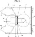
- FIG. 5 is a side view of the fixing device according to the present embodiment.
- FIG. 6A is a perspective view of the fixing device according to the present embodiment.
- FIGS. 6B and 6C are schematic views of the housing frame of the fixing device 9.
- FIG. 6B illustrates a configuration of the fixing device 9 of the present embodiment.
- FIG. 6C illustrates a configuration of a comparative example of a fixing device.
- the housing frame of the fixing device includes a support plate 29 and the pair of side plates 28.
- the support plate 29 is disposed facing the pressure roller 21.
- the pair of side plates 28 are disposed on both ends of the support plate 29 in the longitudinal direction.
- Each side plate 28 has a bearing 28c that supports a rotation shaft of the pressure roller 21.
- the pressure roller 21 is rotatably supported by the side plates 28 with both ends of the rotation shaft fitted in the bearings 28c of the side plates 28.
- the side plate 28 has a substantially C-shape with an opening for supporting the pressure roller 21, and the substantially C-shape have protruding ends 28a, each of which gradually becomes narrower toward the tip thereof.
- the two protruding ends 28a are disposed across an opening of the substantially C-shape and on each one of the pair of right and left side plates 28, and the housing frame as a whole has four protruding ends 28a.
- a drive transmission gear 31 as an example of a driving force transmitter is disposed at one axial end of the rotation shaft of the pressure roller 21.
- the drive transmission gear 31 is disposed to be exposed outward relative to the side plate 28 in a state in which the pressure roller 21 is supported by the side plate 28.
- the flanges 32 support the fixing belt 20 in a state in which the fixing belt 20 is not basically applied with tension in a circumferential direction of the fixing belt 20 while the fixing belt 20 does not rotate, that is, by a free belt method.
- each flange 32 and the support plate 29 a pair of springs as an example of biasing members is disposed. As the springs 33 bias the flanges 32 toward the pressure roller 21, the fixing belt 20 is pressed against the pressure roller 21 to form the nip N between the fixing belt 20 and the pressure roller 21.
- the pair of side plates 28 are attached to at least one of the separation plate 25, the guide plate 26, and the stay 24 on the fixing belt 20.
- Two or more members selected from the group consisting of the separation plate 25, the guide plate 26, and the stay 24 are preferably used to hold the pair of side plates 28.
- the combination of the two members is preferably a combination of the separation plate 25 and the guide plate 26.
- a comparative example of a fixing device includes a fixing stay 40 as a member constituting part of a housing frame.
- the fixing stay 40 positions and fixes a pair of side plates 28 together with a support plate 29 to stabilize the housing frame.
- the side plates 28 can be positioned and fixed by at least one of the separation plate 25, the guide plate 26, and the stay 24, which are existing constituent members. Accordingly, the fixing stay 40, which is a large-size member constituting one longitudinal side of the housing frame can be omitted, thus allowing the housing frame to be stabilized while achieving weight saving of the fixing device 9 and reduction of component costs. Stabilizing the housing frame can also prevent constituent members disposed inside from falling or dropping.
- each longitudinal end of the separation plate 25 and each side plate 28 has an engaging part and the other has an engaged part.
- the engaging part engages with the engaged part to determine the relative positions, and the separation distance of the pair of side plates 28 is defined.
- the manner of the engagement include fitting and fastening.
- the side plates 28 are attached to the separation plate 25 disposed above the fixing belt 20, and thus the upper separation distance between the pair of side plates 28 is defined.
- the separation distance between the pair of side plates 28 on the same side as the pressure roller 21 with respect to the nip N is defined by the support plate 29. Accordingly, when the separation distance between the pair of side plates 28 on the same side as the fixing belt 20 with respect to the nip N is defined by the separation plate 25, the housing frame of the fixing device 9 is maintained in a stable state.
- each longitudinal end of the guide plate 26 and each side plate 28 has an engaging part and the other has an engaged part.
- the engaging part engages with the engaged part to determine the relative positions, and the separation distance of the pair of side plates 28 is defined.
- the manner of the engagement include fitting and fastening.
- the side plate 28 is attached to the guide plate 26 disposed below the fixing belt 20, and thus the lower separation distance of the pair of side plates 28 is defined.
- the separation distance between the pair of side plates 28 on the same side as the pressure roller 21 with respect to the nip N is defined by the support plate 29. Accordingly, when the separation distance between the pair of side plates 28 on the same side as the fixing belt 20 with respect to the nip N is defined by the guide plate 26, the housing frame of the fixing device 9 is maintained in a stable state.
- each longitudinal end of the stay 24 and each side plate 28 has a fitting part and the other has a fitted part.
- the fitting part engages with the fitted part to determine the relative positions, and the separation distance of the pair of side plates 28 is defined.
- the separation distance between the pair of side plates 28 on the same side as the pressure roller 21 with respect to the nip N is defined by the support plate 29. Accordingly, when the separation distance between the pair of side plates 28 on the same side as the fixing belt 20 with respect to the nip N is defined by the stay 24, the housing frame of the fixing device 9 is maintained in a stable state.
- the separation plate 25, the guide plate 26, and the stay 24 that hold the side plates 28 are preferably metal members.
- the combinations of engaging portions and engaged portions include, for example, both a combination in which the separation distance between the pair of side plates 28 is defined by the separation plate 25 and a combination in which the separation distance between the separation plate 25 and the fixing belt 20 is defined by positioning of the side plates 28 and the separation plate 25 relative to each other.
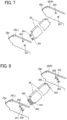
- FIGS. 7 to 11 are diagrams illustrating examples in which the separation plate 25 holds the side plates 28.
- FIGS. 7 to 11 illustrate the examples of holding the side plates 28 by the separation plate 25, the guide plate 26 can also have a similar configuration.
- the pair of side plates 28 are a left side plate 28L and a right side plate 28R.
- both longitudinal ends of the separation plate 25 have bent surfaces facing the side plates 28.
- the bent surfaces have screw holes 301 as engaging portions.
- screw holes 201 as engaged sections are disposed at predetermined positions in the side plates 28.
- Screw members are inserted through the screw holes 301 of the separation plate 25 and the screw holes 201 of the side plates 28 from the outside to fasten the separation plate 25 and the side plates 28 together.
- the separation distance between the pair of side plates 28 is defined by the length of the separation plate 25.
- the separation plate 25 is positioned relative to the side plates 28, the separation distance from the fixing belt 20 is defined.
- screw holes are disposed at one engagement point in FIG. 7 , the number of screw holes is not limited to two.
- both longitudinal ends of the separation plate 25 have bent surfaces facing the side plates 28.
- the bent surfaces have screw holes 301 as engaging portions and two bosses (convex portions) 302.
- screw holes 201 as fitted portions and fitting holes 202 into which the bosses 302 fit are disposed at predetermined positions of the side plates 28.
- the bosses 302 of the separation plate 25 and the fitting holes 202 of the side plates 28 are fitted with each other, and screw members are inserted from outside into the screw holes 301 of the separation plate 25 and the screw holes 201 of the side plates 28 to fasten the separation plate 25 and the side plates 28 together.
- the separation plate 25 and the side plates 28 are fastened and fixed to each other, and the separation distance between the pair of side plates 28 is defined by the length of the separation plate 25.
- the separation plate 25 and the side plates 28 are positioned relative to each other, and the separation distance between the separation plate 25 and the fixing belt 20 is defined.
- FIG. 8 one screw hole, two bosses, and two fitting holes are disposed at one engagement position, but the number of each of screw hole, boss, and fitting hole is not limited to the example of FIG. 8 .
- both longitudinal ends of the separation plate 25 have bent surfaces facing the side plates 28.
- the bent surfaces have screw holes 301 as engaging portions.
- each longitudinal end of the separation plate 25 has a protruding structure 303 as an example of an engaging portion that extends horizontally without being bent.
- screw holes 201 as an example of fitted portions and fitting holes 203 into which the protruding structures 303 fit are disposed at predetermined positions of the side plates 28.
- the protruding structures 303 of the separation plate 25 and the fitting holes 203 of the side plates 28 are fitted with each other, and screw members are inserted from outside into the screw holes 301 of the separation plate 25 and the screw holes 201 of the side plates 28 to fasten the separation plate 25 and the side plates 28 together.
- the separation plate 25 and the side plates 28 are fastened and fixed to each other, and the separation distance between the pair of side plates 28 is defined by the length of the separation plate 25.
- the separation plate 25 and the side plates 28 are positioned relative to each other, and the separation distance between the separation plate 25 and the fixing belt 20 is defined.
- one screw hole, one protruding structure, and one fitting hole are disposed at one engagement position, but the number of each of screw hole, protruding structure, and fitting hole is not limited to the example of FIG. 9 .
- both longitudinal ends of the separation plate 25 have protruding structures 303 as engaging portions extending horizontally and engagement recesses 304.
- fitting holes 203 into which the protruding structures 303 fit and engagement recesses 204 that engage with the engagement recesses 304 are disposed at predetermined positions of the side plates 28.
- the protruding structures 303 of the separation plate 25 and the fitting holes 203 of the side plates 28 are fitted with each other, and the engagement recesses 304 of the separation plate 25 and the engagement recesses 204 of the side plates 28 are engaged with each other.
- the separation distance between the pair of side plates 28 is defined by the length of the separation plate 25.
- the separation plate 25 and the side plates 28 are positioned relative to each other, and the separation distance between the separation plate 25 and the fixing belt 20 is defined.
- the shape of the engagement recesses and the shapes of the protruding structures and the fitting holes are not limited thereto.
- both longitudinal ends of the separation plate 25 have protruding structures 303 as engaging portions extending horizontally and engagement recesses 305 in a bent side face.
- fitting holes 203 into which the protruding structures 303 fit and engagement recesses 205 that engage with the engagement recesses 305 are disposed at predetermined positions of the side plates 28.
- the protruding structures 303 of the separation plate 25 and the fitting holes 203 of the side plates 28 are fitted with each other, and the engagement recesses 305 of the separation plate 25 and the engagement recesses 205 of the side plates 28 are engaged with each other.
- the separation distance between the pair of side plates 28 is defined by the length of the separation plate 25.
- the separation plate 25 and the side plates 28 are positioned relative to each other, and the separation distance between the separation plate 25 and the fixing belt 20 is defined.
- the shape of the engagement recesses and the shapes of the protruding structures and the fitting holes are not limited thereto.
- installation frame a fixing-device installation frame (hereinafter may be referred to simply as "installation frame") 105 of the image forming apparatus 100 and is positioned and fixed to the fixing-device installation frame 105.
- FIG. 12 is a perspective view of the fixing device 9 and the fixing-device installation frame 105 according to the present embodiment.
- FIG. 13A is a perspective view of the fixing device 9 according to the present embodiment attached to the fixing-device installation frame 105.
- FIGS. 13B and 13C are schematic diagrams of a housing frame of the fixing device 9 and the installation frame 105 of the image forming apparatus 100.
- FIG. 13B illustrates a configuration of the present embodiment
- FIG. 13C illustrates a configuration of a comparative example.
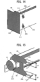
- FIG. 14 is a partial perspective view of the fixing device 9 attached to the fixing-device installation frame 105 of FIG. 13A , viewed from the opposite side.
- the support plate 29 of the fixing device 9 has through holes 29a through which a fixing means for positioning and fixing the fixing device 9 to the image forming apparatus 100 (installation frame 105) is inserted.
- the installation frame 105 of the image forming apparatus 100 has slit-shaped insertion holes 111 and fixing portions 112. Protruding ends 28a of the side plates 28 are inserted into the slit-shaped insertion holes 111.
- the fixing portions 112 have the fixing means to engage with or fit into the through holes 29a of the support plate 29.
- the insertion holes 111 are disposed in an installation frame wall 110.
- Each fixing portion 112 projects from an end portion of a side wall 120 of the installation frame 105 and disposed opposite the installation frame wall 110.
- the manner in which the fixing device 9 is positioned and fixed relative to the installation frame 105 is determined by the arrangement positions, shape, and dimension of the protruding ends 28a and the arrangement positions, shape, and dimension of the insertion holes 111.
- the four protruding ends 28a of the side plates 28 of the fixing device 9 are inserted into the corresponding four insertion holes 111.
- the pair of side plates 28 are also held by the installation frame wall 110 of the installation frame 105 on the same side as the fixing belt 20 with respect to the nip N in the direction intersecting the longitudinal direction of the support plate 29. Further, since the housing frame of the fixing device 9 is held in the up-down direction, the posture of the fixing device 9 is stable in the up-down and right-left directions.
- one of the two through holes 29a on both longitudinal ends of the support plate 29 is fastened to the fixing portion 112 by a screw 115, and the other is fitted with an embossed portion 114 disposed on the fixing portion 112.
- the fixing device 9 is positioned and fixed relative to the installation frame 105 in the front-rear direction.
- the fixing device 9 is positioned in the up-down and right-left directions by insertion of the protruding ends 28a into the insertion holes 111.
- a comparative example of a fixing device includes a fixing stay 40 as a member constituting a housing frame.
- the fixing stay 40 positions and fixes a pair of side plates 28 together with a support plate 39, and stabilizes a housing.
- the side plates 28 are positioned and fixed by at least one of the separation plate 25, the guide plate 26, and the stay 24.
- the side plates 28 are also held by the installation frame wall 110, so that the housing frame can obtain sufficient stability even if the fixing stay 40 is omitted.
- the housing frame Since the housing frame is stable, the drive transmission from the image forming apparatus 100 and the sheet conveyance are also stable. Thus, a high-precision image is obtained.
- FIG. 15 is a perspective view the side plate 28, illustrating dimensions of the side plate 28.
- T represents a plate thickness of the protruding ends 28a of the side plate 28.
- the length of the upper protruding end 28a of the substantially C-shape of the side plate 28 is denoted by h1
- the length of the lower protruding end 28a of the substantially C-shape of the side plate 28 is denoted by h2.
- FIG. 16 is a front view of the installation frame wall 110, illustrating the dimensions of the insertion holes 111.
- the lengths of openings of two upper insertion holes 111 are indicated by H1, and the lengths of openings of two lower insertion holes 111 are indicated by H2.
- the insertion hole 111 has a slit shape in which a central part is wide.
- W represents the width of the narrowest part of the insertion hole 111.
- the width of an upper-right insertion hole 111 in FIG. 16 is represented by W1
- the width of a lower-right insertion hole 111 is represented by W2
- the width of an upper-left insertion hole 111 is represented by W3
- the width of a lower-left insertion hole 111 is represented by W4.
- the two upper insertion holes 111 are disposed at target positions for positioning and fixing the protruding ends 28a, and the length H1 of the two upper insertion holes 111 is set to be substantially equal to the length h1 of the upper protruding ends 28a.
- the length H2 of the two lower insertion holes 111 is set to be greater than the length h2 of the lower protruding ends 28a.
- the upper protruding ends 28a and the upper insertion holes 111 in the step are fitted with each other, and positioned and fixed at correct positions.
- the two lower insertion holes 111 have openings longer than the inserted lower protruding ends 28a, the lower protruding ends 28a are not fixed in the up-down direction. Thus, an error due to dimensional variation and an attachment error can be absorbed.
- each of the side plates 28 is attached to and positioned by the separation plate 25 disposed above the fixing device 9.
- the separation distance between the pair of side plates 28 is accurately defined only on the upper side.
- the two lower insertion holes 111 and the pair of side plates 28 are set to define a target separation distance, and each of the widths W2 and W4 of the two lower insertion holes 111 is set to be substantially equal to the plate thickness T of the protruding end 28a. Further, each of the widths W1 and W3 of the two upper insertion holes 111 is set to be wider than the plate thickness T of the protruding end 28a.
- the lower separation distance of the side plates 28 whose protruding ends 28a are inserted in the insertion holes 111 is also accurately defined.
- the upper separation distance between the side plates 28 is accurately defined by the separation plate 25, thus obviating the need of being held by the installation frame 105 for adjustment.
- the widths W1 and W3 of the two upper insertion holes 111 be set to be wider than the plate thickness T of the upper protruding ends 28a to be inserted and that there be play therebetween.
- each of the side plates 28 is attached to and positioned by the guide plate 26 disposed below the fixing device 9.
- the separation distance between the pair of side plates 28 is accurately defined only on the lower side.
- the two upper insertion holes 111 and the pair of side plates 28 are set to define a target separation distance, and each of the widths W1 and W3 of the two upper insertion holes 111 is set to be substantially equal to the plate thickness T of the protruding end 28a.
- Each of the widths W2 and W4 of the two lower insertion holes 111 is set to be wider than the plate thickness T of the protruding end 28a.
- the upper separation distance of the side plates 28 whose protruding ends 28a are inserted in the insertion holes 111 is also accurately defined. An effect due to interference of the installation frame 105 can also be avoided.
- FIG. 17 is a partial perspective view of the fixing device 9 and the installation frame 105, and also illustrates an enlarged view of the insertion hole 111.
- the insertion hole 111 has a wide portion 111b that is a central portion expanded from a region 111a of a slit in which a protruding end 28a of the side plate 28 is disposed.
- the protruding end 28a When the fixing device 9 is attached to the installation frame 105, the protruding end 28a may be inserted with displacement relative to an intended position of the insertion hole 111. Even in such a case, the wide portion 111b provided as a play (clearance) allows the installation frame wall 110 to be attached without causing an adverse effect.
- the protruding end 28a has a shape of being gradually narrower toward the tip of the protruding end 28a.
- the wide portion 111b has a shape of being inclined toward the region 111a. Accordingly, even when the protruding end 28a is inserted in a shifted position (wide portion 111b), the protruding end 28a is smoothly guided to the target position (region 111a).
- Such a configuration enhances the workability in attachment and removal of the fixing device 9 as a unit, and facilitates assembly.
- the through holes 29a of the support plate 29 and the fixing portions 112 of the installation frame 105 will be described with reference to FIGS. 18A, 18B, 19A, and 19B .
- the installation frame 105 is provided with a pair of fixing portions 112 for fixing the support plate 29.
- Each fixing portion 112 projects from an end portion of a side wall 120 of the installation frame 105 and are disposed opposite the installation frame wall 110, and includes screw holes 113 and embossed portions 114 to fit into embossment through holes 292 among the through holes 29a of the support plate 29.
- FIG. 18B is a front view of the installation frame 105 attached with the fixing device 9.
- the embossed portions 114 are fitted into the embossment through holes 292 of the support plate 29 to position the fixing device 9.
- the screw holes 113 and the screw holes 291 of the support plate 29 are fastened together with screws 115, thus fixing the fixing device 9.
- the fixing device 9 is also positioned by insertion and fitting of the protruding ends 28a of the side plate 28 to the insertion holes 111 of the installation frame wall 110.
- FIGS. 19A and 19B a configuration may be adopted in which only screw holes 113 are disposed in the fixing portions 112 and similarly only screw holes 291 are disposed in the support plate 29 such that the screw holes 113 and the screw holes 291 are fastened together with screws 115.
- the apparatus size and functions can be further optimized.
- the fixing device of the present embodiment and the image forming apparatus including the fixing device size reduction, weight reduction, and cost reduction of the apparatus, as well as stabilization and accurate positioning of the housing frame, can be achieved.
- the above-described configuration is also applicable to a fixing device and an image forming apparatus according to different embodiments.
- the fixing device 9 illustrated in FIG. 20 includes, as a heat source, a planar or plate-shaped heater 22 in which resistive heating elements 56 are disposed on a base 55.
- the base 55 is made of ceramic such as alumina and aluminum nitride, or heat-resistant and insulating material such as glass, mica, and polyimide. Further, the base 55 may be a metal material such as stainless steel, iron, and aluminum, on which an insulation layer is formed.
- the resistive heating element 56 is formed by coating a paste, in which, for example, silver palladium (AgPd) and glass powder are mixed, on the surface of the base 55 by screen printing or any other method, and then firing the base 55.
- the resistive heating element 56 is covered with an insulation layer 57.
- the insulation layer 57 is made of a material such as heat-resistant glass, ceramic, or polyimide.
- the heater 22 has a shape of a rectangular plate and is disposed such that the longitudinal direction thereof be parallel to the longitudinal direction of the fixing belt 20.
- the plurality of resistive heating elements 56 are disposed at intervals in the longitudinal direction of the base 55 (heater 22).
- a plurality of electrodes 58 and a plurality of power feeding lines 59 are disposed on the surface of the base 55 on which the resistive heating elements 56 are disposed.
- the resistive heating elements 56 are connected in parallel to the electrodes 58 disposed at both ends of the base 55 in the longitudinal direction via the power feeding lines 59.
- the resistive heating elements 56 and the power feed lines 59 are covered with the insulation layer 57.
- the electrodes 58 are not covered with the insulation layer 57 and are exposed such that connectors as power feeding terminals are connectable to the electrodes 58.
- the heater 22 is held by the heater holder 23 and is disposed in contact with an inner circumferential surface of the fixing belt 20. Accordingly, when the heater 22 generates heat, the fixing belt 20 is heated from inside.
- the fixing belt 20 and the pressure roller 21 of FIG. 20 have basically the same configurations as those of the fixing belt and the pressure roller according to the above-described embodiment.
- the heater holder 23 is integrated with guides 66.
- the guides 66 are disposed upstream and downstream from the nip N in a rotation direction of the fixing belt 20. When the fixing belt 20 rotates, the guides 66 contact the inner circumferential surface of the fixing belt 20 to guide the fixing belt 20 from the inside of the fixing belt 20.
- a temperature sensor 67 as an example of a temperature detector is disposed to detect the temperature of the heater 22.
- the temperature sensor 67 is pressed by a spring 70.
- the temperature sensor 67 illustrated in FIG. 20 is a contact-type temperature sensor that contacts a surface of the heater 22 opposite the nip N to detect the temperature of the heater 22.
- a contactless-type temperature sensor may be disposed in non-contact with the heater 22 to detect the ambient temperature in the vicinity of the heater 22.
- the fixing device 9 when power is supplied to the heater 22 from a power source disposed in a body of an image forming apparatus, resistive heating elements 56 generate heat. Thus, the fixing belt 20 is heated. The amount of heat generated by the heater 22 is controlled on the basis of the temperature of the heater 22 detected by the temperature sensor 67. Thus, the temperature of the fixing belt 20 is maintained at a predetermined temperature (fixing temperature). In this state, as illustrated in FIG. 20 , a sheet P bearing unfixed toner enters a space (nip N) between the fixing belt 20 and the pressure roller 21, so that the unfixed toner on the sheet P is pressed and heated, and a toner image is fixed on the sheet P.
- fixing temperature fixing temperature
- the temperature sensor 67 may be located at the center M of the nip N in the sheet conveyance direction as illustrated in FIG. 20 , or may be located upstream from the center M of the nip N in the sheet conveyance direction as in the example illustrated in FIG. 22 . In other words, the temperature sensor 67 may be disposed on the inlet side of the nip N.
- the inlet side of the nip N is a region where the heat of the fixing belt 20 is particularly prone to be lost by the sheet P entering the nip N. For this reason, detecting the temperature of the inlet side with the temperature sensor 67 can ensure the fixing performance of an image and to effectively reduce the occurrence of fixing offset in which a toner image cannot be sufficiently heated.
- a pressure roller 69 is disposed opposite the pressure roller 21 with respect to the fixing belt 20.
- the pressure roller 69 is a counter rotator that rotates at the position facing the fixing belt 20 that is an example of a rotator.
- the fixing belt 20 is sandwiched by the pressure roller 69 and the heater 22 and is heated by the heater 22.
- a nip formation pad 68 as an example of a nip former is disposed inside the loop formed by the fixing belt 20 and disposed opposite the pressure roller 21.
- the nip formation pad 68 is attached to the stay 24.
- the nip formation pad 68 sandwiches the fixing belt 20 together with the pressure roller 21 to form a fixing nip N.
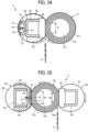
- the above-described pressure roller 69 is omitted, and the heater 22 is formed in an arc shape to match the curvature of the fixing belt 20 in order to ensure a circumferential contact length between the fixing belt 20 and the heater 22.
- Other parts of the fixing device 9 illustrated in FIG. 24 are the same as the fixing device 9 illustrated in FIG. 23 .
- the fixing device 9 illustrated in FIG. 25 includes a heating assembly 92, a fixing roller 93 as an example of a fixing member, and a pressure assembly 94 as an example of a counter member.
- the heating assembly 92 includes the heaters 22, the heater holders 23, the stay 24, and the heating belt 99 as an example of a rotator, as described in the above-described embodiment.
- the fixing roller 93 is a counter rotator that rotates and faces the heating belt 99, which is an example of a rotator.
- the fixing roller 93 includes a core 93a, an elastic layer 93b, and a release layer 93c.
- the core 93a is a solid core made of iron.
- the elastic layer 93b covers the surface of the core 93a.
- the release layer 93c covers an outer circumferential face of the elastic layer 93b.
- the pressure assembly 94 is disposed opposite the heating assembly 92 with respect to the fixing roller 93.
- the pressure assembly 94 includes a nip formation pad 95, a stay 96, and a pressure belt 97.
- the pressure belt 97 is rotatably disposed to surround the nip formation pad 95 and the stay 96.
- a sheet P is heated and pressed while passing through a fixing nip N2 between the pressure belt 97 and the fixing roller 93, so that an image is fixed on the sheet P.
- An image forming apparatus is not limited to a color image forming apparatus as illustrated in FIG. 1 and may be, for example, a monochrome image forming apparatus, or may be a copier, a printer, a facsimile machine, or a multifunction peripheral including at least two functions of the copier, printer, and facsimile machine.
- An image forming apparatus may be, for example, an image forming apparatus having a configuration as illustrated in FIG. 26 .
- An image forming apparatus 100 illustrated in FIG. 26 includes an image forming device 80 including a photoconductor drum, a sheet conveyor including a timing roller pair 81, a sheet feeder 82, a fixing device 9, a sheet ejection device 84, and a reading device 85.
- the sheet feeder 82 includes a plurality of sheet feeding trays, and the sheet feeding trays store sheets of different sizes.
- the reading device 85 reads an image of an original document Q.
- the reading device 85 generates image data from the read image.
- the sheet feeder 82 stores the plurality of sheets P and feeds the sheet P to a conveyance path.
- the timing roller pair 81 conveys the sheet P on the conveyance path to the image forming device 80.
- the image forming device 80 forms a toner image on the sheet P.
- the image forming device 80 includes the photoconductor drum, a charging roller, an exposure device, a developing device, a supply device, a transfer roller, a cleaning device, and a charge neutralizing device.
- the toner image is, for example, an image of the original document Q.
- the fixing device 9 heats and presses a toner image to fix the toner image on the sheet P.
- Conveyance rollers convey the sheet P, on which the toner image has been fixed, to the sheet ejection device 84.
- the sheet ejection device 84 ejects the sheet P to the outside of the image forming apparatus 100.
- the fixing device 9 includes a fixing belt 20, a pressure roller 21, a heater 22, a heater holder 23, a stay 24, and a temperature sensor 67.
- a fixing nip N is formed between the fixing belt 20 and the pressure roller 21.
- the nip width of the fixing nip N is 10 mm, and the linear velocity of the fixing device 9 is 240 mm/s.
- the fixing belt 20 includes a polyimide base and a release layer and does not include an elastic layer.
- the release layer is formed with a heat-resistant film material made of, for example, fluororesin.
- the outer diameter of the fixing belt 20 is about 24 mm.
- the pressure roller 21 includes a core 21a, an elastic layer 21b, and a release layer 21c.
- the pressure roller 21 has an outer diameter of 24 mm to 30 mm, and the elastic layer 21b has a thickness of 3 mm to 4 mm.
- the heater 22 includes a base, a thermal insulation layer, a conductor layer including resistive heating elements, and an insulation layer, and is formed to have a thickness of 1 mm as a whole.
- a width Y of the heater 22 in a direction intersecting an arrangement direction of the resistive heating elements is 13 mm.
- the conductor layer of the heater 22 includes a plurality of resistive heating elements 56, power feeding lines 59, and electrodes 58A, 58B, and 58C.
- separation areas B are formed between neighboring resistive heating elements of the plurality of resistive heating elements 56 arranged in the arrangement direction.
- the enlarged view of FIG. 28 illustrates two separation areas B, but separation areas B are formed between neighboring ones of all the plurality of resistive heating elements 56.
- the resistive heating elements 56 are grouped to three heat generation portions 35A, 35B, and 35C. When the electrodes 58A and 58B are energized, the heat generation portions 35A and 35C generate heat.
- the heat generation portion 35B When the electrodes 58A and 58C are energized, the heat generation portion 35B generates heat. When the fixing device 9 fixes a toner image onto a small-size sheet, the heat generation portion 35B generates heat. When the fixing device 9 fixes a toner image onto a large-size sheet, the whole heat generation portions 35Am 35B, and 35C generate heat.
- the heater holder 23 has a recessed portion 23b that accommodates and holds the heater 22.
- the recessed portion 23b is formed on a side of the heater holder 23 facing the heater 22.
- the recessed portion 23b has a face (bottom face) 23b1 and four walls (side faces) 23b2 and 23b3.
- the face 23b1 has a rectangle (oblong) shape of substantially the same size as the heater 22.
- the four walls 23b2 and 23b3 are disposed to intersect the face 23b1 along four sides forming the outline of the face 23b1.
- one wall 23b2 may be omitted from the pair of walls 23b2 disposed in a direction intersecting a longitudinal direction X of the heater 22 (a direction in which the resistive heating elements 56 are arranged), and the recessed portion 23b may be formed to be open at one end in the longitudinal direction of the heater 22.
- the connector 86 includes a housing made of resin such as liquid crystal polymer (LCP) and a plurality of contact terminals disposed inside the housing.
- LCP liquid crystal polymer
- the connector 86 is attached to the heater 22 and the heater holder 23 such that a front side of the heater 22 and the heater holder 23 and a back side of the heater 22 and the heater holder 23 are sandwiched by the connector 60.
- the contact terminals contact and press against the electrodes of the heater 22, and the heat generation portions are electrically coupled to the power supply, which is disposed in the image forming apparatus, via the connector 86.
- the above-described configuration enables the power supply to supply power to the heat generation portions.
- Flanges 32 are inserted into both longitudinal ends of the stay 24 to hold both ends of the fixing belt 20 from inside of the fixing belt 20.
- one of the flanges 32 is inserted into corresponding one of the longitudinal ends of the stay 24 in a direction indicated by an arrow in FIG. 30 .
- the flanges 32 are fixed to a housing of the fixing device 9.
- a configuration of the fixing for example, the configuration illustrated in FIG. 4 can be applied.
- the connector 86 is attached to the heater 22 and the heater holder 23 in the direction intersecting the arrangement direction (e.g., a direction indicated by an arrow from the connector 86 in FIG. 30 ).
- the connector 86 and the heater holder 23 may have a projection and a recess to attach the connector 86 to the heater holder 23.
- the projection disposed on one of the connector 86 and the heater holder 23 is engaged with the recess disposed on the other of the connector 86 and the heater holder 23 and relatively moves in the recess to attach the connector 86 to the heater holder 23.
- the connector 86 is attached to one end of the heater 22 and one end of the heater holder 23 in the arrangement direction, which are opposite the one end of the heater 22 and the one end of the heater holder 23 closer to a drive motor for the pressure roller 21.
- FIG. 31A is a diagram illustrating positions of temperature sensors 67 and thermostats 88 serving as an example of current cut-off members.
- the temperature sensors 67 are disposed facing an inner circumferential surface of the fixing belt 20 at a position closer to the center C and a position closer to one end in the longitudinal direction of the fixing belt 20.
- One of the temperature sensors 67 is disposed at a position corresponding to one of the above-described separation areas B (see FIG. 28 ) between the resistive heating elements of the heater 22.
- the thermostats 88 as an example of current cut-off members are disposed facing the inner circumferential surface of the fixing belt 20 at a position closer to the center C and a position closer to the other end in the longitudinal direction of the fixing belt 20.
- Each thermostat 88 detects the temperature of the inner circumferential surface of the fixing belt 20 or the ambient temperature in the vicinity of the inner circumferential surface of the fixing belt 20.
- the thermostat 88 cuts off the current flowing to the heater 22 in response to detection of the temperature that exceeds a preset threshold value.
- guide grooves 32a are disposed in the flanges 32 that hold both ends of the fixing belt 20 in the longitudinal direction.
- the guide groove 32a extends in a direction in which the fixing belt 20 moves toward or away from the pressure roller 21.
- the guide grooves 32a are engaged with a housing frame (side plates 28) of the fixing device 9, and the housing frame of the fixing device 9 relatively moves within the guide grooves 32a.
- the fixing belt 20 is movable in the direction toward or away from the pressure roller 21.
- Some embodiments of the present disclosure are also applicable to a fixing device having the following configuration.
- FIG. 32 is a schematic view of a fixing device 9 according to an embodiment of the present disclosure.
- the fixing device 9 includes a fixing belt 20 as a rotating body or a fixing member, a pressure roller 21 as an opposing rotating body or a pressure member, a heater 22 as a heat source, a heater holder 23 as a heat-source holder, a stay 24 as a flange, a temperature sensor (thermistor) 67 as a temperature detector, and a first high-thermal conduction member 89.
- the temperature sensor 67 detects the temperature of the first high-thermal conduction member 89.
- the stay 24 has two upright portions 240 extending in the thickness direction of the heater 22 and each having a contact face 241 that contacts the heater holder 23 to hold the heater holder 23, the first high-thermal conduction member 89, and the heater 22.
- the contact face 241 is located outside an area where resistive heating elements 56 of the heater 22 are arranged, in a direction (vertical direction in FIG. 32 ) intersecting the arrangement direction of the resistive heating elements 56.
- the heater holder 23 is provided with guides 66 that guide the fixing belt 20.
- the guides 66 are disposed upstream and downstream from the heater 22 in a rotation direction (belt rotation direction) of the fixing belt 21. Upstream ones of the guides 66 are disposed at intervals in the longitudinal direction of the heater 22. Downstream ones of the guides 66 are also disposed at intervals in the longitudinal direction of the heater 22.
- Each guide 66 is formed in a substantially fan shape, and has an arc-shaped or convexly curved belt-facing surface extending in a circumferential direction of the fixing belt 20 so as to face the inner circumferential surface of the fixing belt 20.
- a plurality of resistive heating elements 56 are arranged at intervals in the longitudinal direction of the heater 22.
- the temperature of the heater 22 in the separation area B corresponding to the interval between adjacent two of the resistive heating elements 56 is likely to be lower than the temperature of the heater 22 in a portion entirely occupied by any one of the resistive heating elements 56. For this reason, the temperature of the fixing belt 20 corresponding to the separation area B is also lower, which may cause an uneven temperature distribution of the fixing belt 20 in the longitudinal direction.
- the fixing device 9 includes the first high-thermal conduction member 89 described above. A detailed description is given below of the first high-thermal conduction member 89.
- the first high-thermal conduction member 89 is disposed between the heater 22 and the stay 24 in the right-left direction in the drawing and is sandwiched between the heater 22 and the heater holder 23.
- One side of the first high-thermal conduction member 89 is brought into contact with the back surface of the base 55 of the heater 22, and the other side (that is, the side opposite to the one side) of the first high-thermal conduction member 89 is brought into contact with the heater holder 23.
- the first high-thermal conduction member 89 is a plate-shaped member having a uniform thickness, and is set to, for example, 0.3 mm thick, 222 mm long in the longitudinal direction, and 10 mm wide in the direction intersecting the longitudinal direction.
- the first high-thermal conduction member 89 is made of a single plate but may be made of a plurality of members.
- the guides 66 illustrated in FIG. 32 are omitted.
- the first high-thermal conduction member 89 is fitted into the recessed portion 23b of the heater holder 23, and the heater 22 is mounted on the first high-thermal conduction member 89.
- the first high-thermal conduction member 89 is sandwiched and held between the heater holder 23 and the heater 22.
- the length of the first high-thermal conduction member 89 in the longitudinal direction is substantially the same as the length of the heater 22 in the longitudinal direction.
- the recessed portion 23b has opposite sidewalls (longitudinal-direction restricting portions) 23b1 arranged in a direction intersecting the longitudinal direction to restrict the first high-thermal conduction member 89 and the heater 22 from moving in the longitudinal direction.
- the recessed portion 23b also has opposite sidewalls (arrangement-intersecting-direction restricting portions) 23b2 arranged in the longitudinal direction to restrict the first high-thermal conduction member 89 and the heater 22 from moving in the longitudinal intersection direction.
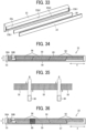
- the range in which the first high-thermal conduction member 89 is disposed in the longitudinal direction indicated by the arrow X is not limited to the range illustrated in FIG. 33 .
- the first high-thermal conduction member 89 may be disposed only in the longitudinal range where the resistive heating elements 56 are disposed (see the hatched portion in FIG. 34 ).
- first high-thermal conduction members 89 may be disposed only in all areas corresponding to the intervals (separation areas) B in the longitudinal direction (the direction indicated by arrow X).
- the resistive heating elements 56 and the first high-thermal conduction members 89 are shifted in the vertical direction of FIG. 35 but are disposed at substantially the same position in the direction intersecting the longitudinal direction indicated by an arrow Y
- the first high-thermal conduction member 89 may be disposed over a part of the resistive heating element 56 in the direction intersecting the longitudinal direction (the direction indicated by the arrow Y), or as in the example illustrated in FIG. 36 , may be disposed to cover all the resistive heating element 56 in the direction intersecting the longitudinal direction (the direction indicated by the arrow Y
- first high-thermal conduction members 89 in addition to first high-thermal conduction members 89 located at positions corresponding to the separation areas B in the longitudinal direction, one or more first high-thermal conduction members 89 may be disposed such that one first high-thermal conduction member 89 straddles adjacent two resistive heating elements 56 with the separation area B interposed therebetween.
- the phrase "one first high-thermal conduction member 89 straddles adjacent two resistive heating elements 56" means that one first high-thermal conduction member 89 at least partially overlap each of the two resistive heating elements 56 on both sides in the longitudinal direction.
- the first high-thermal conduction members 89 may be disposed at positions corresponding to all of the separation areas B of the heater 22, or as in the example illustrated in FIG.
- the first high-thermal conduction members 89 may be disposed at positions corresponding to the separation areas B" means that at least a part of the first high-thermal conduction member 89 may overlap the separation area B in the longitudinal direction.
- the first high-thermal conduction member 89 is sandwiched between the heater 22 and the heater holder 23 and is brought into close contact with the heater 22 and the heater holder 23. Bringing the first high-thermal conduction member 89 into contact with the heater 22 enhances the heat conduction efficiency in the longitudinal direction of the heater 22.
- the first high-thermal conduction members 89 are disposed at the positions corresponding to the separation areas B in the longitudinal direction. Thus, the heat conduction efficiency of the separation areas B can be enhanced, the amount of heat transmitted to the separation areas B can be increased, and the temperature of the separation areas B can be raised.
- the first high-thermal conduction members 89 can reduce the temperature unevenness of the heater 22 in the longitudinal direction and the temperature unevenness of the fixing belt 20 in the longitudinal direction.
- the above-described structure can prevent uneven fixing and uneven gloss in the image fixed on the sheet. Since the heater 22 does not need to generate additional heat to obtain a sufficient fixing performance in the part of the heater 23 facing the separation areas B, energy consumption of the fixing device can be saved.
- the first high-thermal conduction member 89 disposed over the entire area in which the resistive heating elements 56 are arranged in the longitudinal direction enhances the heat transfer efficiency of the heater 22 over the entire area of a main heating region of the heater 22 (that is, an area facing an image formation area of the sheet passing through the fixing device) and reduces the temperature unevenness of the heater 22 and the temperature unevenness of the fixing belt 20 in the longitudinal direction.
- the combination of the first high-thermal conduction member 89 and the resistive heating element 56 having a positive temperature coefficient (PTC) characteristic effectively prevents the overheating of the non-sheet passing region (that is the region of the fixing belt that is not in contact with a small-size sheet) of the fixing belt 20 when small-size sheets pass through the fixing device 9.
- the PTC characteristic is a characteristic in which the resistance value increases as the temperature increases, for example, a heater output decreases under a constant voltage.
- the resistive heating element 56 having the PTC characteristic effectively reduces the amount of heat generated by the resistive heating element 56 in the non-sheet passing region, and the first high-thermal conduction member 89 effectively transfers heat from the non-sheet passing region in which the temperature rises to a sheet passing region that is a region of the fixing belt contacting the sheet. As a result, the overheating of the non-sheet passing region is effectively prevented.
- the first high-thermal conduction member 89 may be disposed opposite an area around the separation area B because the small heat generation amount in the separation area B decreases the temperature of the heater 22 in the area around the separation area B.
- the first high-thermal conduction member 89 facing an enlarged separation area C that includes the separation area B and an area around the separation area B as illustrated in FIG. 37 improves the heat transfer efficiency of the separation area B and the area around the separation area B in the longitudinal direction and effectively reduces the temperature unevenness in the longitudinal direction of the heaters 22.
- the temperature unevenness in the longitudinal direction of the heater 22 (fixing belt 20) can be more reliably reduced.
- a fixing device 9 illustrated in FIG. 38 includes a second high-thermal conduction member 90 between a heater holder 23 and a first high-thermal conduction member 89.
- the second high-thermal conduction member 90 is disposed at a position different from the position of the first high-thermal conduction member 89 in the left-to-right direction in FIG. 38 that is a direction in which the heater holder 23, the stay 24, and the first high-thermal conduction member 89 are layered.
- the second high-thermal conduction member 90 is disposed to overlap the first high-thermal conduction member 89.
- a temperature sensor (thermistor) 67 is provided in the present embodiment as in the embodiment illustrated in FIG. 32 described above, FIG. 38 illustrates a cross section where the temperature sensor 67 is not disposed.
- the second high-thermal conduction member 90 is made of a material having thermal conductivity higher than the thermal conductivity of the base 55, for example, graphene or graphite.
- the second high-thermal conduction member 90 is made of a graphite sheet having a thickness of 1 mm.
- the second high-thermal conduction member 90 may be a plate made of aluminum, copper, silver, or the like.
- a plurality of second high-thermal conduction members 90 are disposed in the recessed portion 23b of the heater holder 23, and the second high-thermal conduction members 90 are spaced apart from each other in the longitudinal direction.
- the recessed portion 23b of the heater holder 23 includes dents deeper than the other areas such that the second high-thermal conduction members 90 are disposed in the dents. Clearances are formed between the heater holder 23 and both sides of the second high-thermal conduction member 90 in the longitudinal direction. The clearance prevents heat transfer from the second high-thermal conduction member 90 to the heater holder 23, and the heater 22 efficiently heats the fixing belt 20.
- the guides 66 illustrated in FIG. 32 are omitted.
- the second high-thermal conduction member 90 (see the hatched portion) is disposed at a position corresponding to the separation area B in the longitudinal direction (the direction indicated by arrow X) and at a position at which the second high-thermal conduction member 90 at least partially overlaps each resistive heating element of an adjacent pair of the resistive heating elements 56.
- each of the second high-thermal conduction members 90 in the present embodiment faces the entire separation area B.
- FIG. 40 illustrates the case where the first high-thermal conduction member 89 is disposed over the entirety in the longitudinal direction of the region where all the resistive heating elements 56 are disposed, the arrangement range of the first high-thermal conduction member 89 is not limited thereto.
- the fixing device includes the second high-thermal conduction member 90 disposed at a position corresponding to the separation area B in the longitudinal direction and the position at which at least a part of each of the neighboring resistive heating elements 56 faces the second high-thermal conduction member 90, in addition to the first high-thermal conduction member 89.
- the above-described structure further enhances the heat transfer efficiency in the separation areas B in the longitudinal direction and more efficiently reduces the temperature unevenness of the heater 22 in the longitudinal direction.
- the first high-thermal conduction member 89 and the second high-thermal conduction member 90 are disposed only over the entirety thereof at positions corresponding to the separation areass B.
- the above-described structure enhances the heat transfer efficiency of the part of the heater 23 corresponding to the separation area B to be higher than the heat transfer efficiency of the other part of the heater 23.
- the resistive heating element 56, the first high-thermal conduction member 89, and the second high-thermal conduction member 90 are shifted in the vertical direction of FIG. 40 but are disposed at substantially the same position in the direction intersecting the longitudinal direction indicated by the arrow Y
- the positions of the resistive heating element 56, the first high-thermal conduction member 89, and the second high-thermal conduction member 90 are not limited to the example of FIG. 41 .
- the first high-thermal conduction member 89 and the second high-thermal conduction member 90 may be disposed opposite a part of the resistive heating element 56 in the direction intersecting the longitudinal direction or may be disposed so as to cover the entire resistive heating element 56 in the direction intersecting the longitudinal direction.
- Both the first high-thermal conduction member 89 and the second high-thermal conduction member 90 may be made of a graphene sheet.
- the first high-thermal conduction member 89 and the second high-thermal conduction member 90 made of the graphene sheet have high thermal conductivity in a predetermined direction along the plane of the graphene, that is, not in the thickness direction but in the longitudinal direction. Accordingly, the above-described structure can effectively reduce the temperature unevenness of the fixing belt 20 in the longitudinal direction and the temperature unevenness of the heater 22 in the longitudinal direction.
- Graphene is a flaky powder. Graphene has a planar hexagonal lattice structure of carbon atoms, as illustrated in FIG. 44 .
- the graphene sheet is usually a single layer.
- the graphene sheet may contain impurities in a single layer of carbon or may have a fullerene structure.
- the fullerene structures are typically recognized as compounds including an even number of carbon atoms, which form a cage-like fused ring polycyclic system with five and six membered rings, including, for example, C 60 , C 70 , and C 80 fullerenes or other closed cage structures having three-coordinate carbon atoms.
- Graphene sheets are artificially made by, for example, a chemical vapor deposition (CVD) method.
- CVD chemical vapor deposition
- the graphene sheet is commercially available.
- the size and thickness of the graphene sheet or the number of layers of the graphite sheet described later are measured by, for example, a transmission electron microscope (TEM).
- TEM transmission electron microscope
- Graphite obtained by multilayering graphene has a large thermal conduction anisotropy.
- the graphite has a crystal structure formed by layering a number of layers each having a condensed six-membered ring layer plane of carbon atoms extending in a planar shape.
- adjacent carbon atoms in the layer are coupled by a covalent bond
- carbon atoms between layers are coupled by a van der Waals bond.
- the covalent bond has a greater bonding force than a van der Waals bond. Therefore, there is a large anisotropy between the bond between carbon atoms in a layer and the bond between carbon atoms in different layers.
- the first high-thermal conduction member 89 and the second high-thermal conduction member 90 that are made of graphite each have the heat transfer efficiency in the longitudinal direction greater than the heat transfer efficiency in the thickness direction of the first high-thermal conduction member 89 and the second high-thermal conduction member 90 (that is, the stacking direction of these members), reducing the heat transferred to the heater holder 23. Accordingly, the above-described structure can efficiently decrease the temperature unevenness of the heater 22 in the longitudinal direction and can minimize the heat transferred to the heater holder 23.
- the first high-thermal conduction member 89 and the second high-thermal conduction member 90 that are made of graphite are not oxidized at about 700 degrees or lower, the first high-thermal conduction member 89 and the second high-thermal conduction member 90 each have an excellent heat resistance.
- the physical properties and dimensions of the graphite sheet may be appropriately changed according to the function required for the first high-thermal conduction member 89 or the second high-thermal conduction member 90.
- the anisotropy of the thermal conduction can be increased by using high-purity graphite or single-crystal graphite or increasing the thickness of the graphite sheet.
- Using a thin graphite sheet can reduce the thermal capacity of the fixing device so that the fixing device can perform high-speed printing.
- a width of the first high-thermal conduction member 89 or a width of the second high-thermal conduction member 90 in the direction intersecting the longitudinal direction may be increased in response to a large width of the nip N or a large width of the heater 22.
- the number of layers of the graphite sheet is preferably 11 or more.
- the graphite sheet may partially include a single layer portion and a multilayer portion.
- the configuration of the second high-thermal conduction member 90 is not limited to the configuration illustrated in FIG. 40 .
- a second high-thermal conduction member 90A may be disposed to protrude outward beyond both sides of the base 55 in the direction (the direction indicated by arrow Y) intersecting the longitudinal direction.
- a second high-thermal conduction member 90B faces a range in which the resistive heating elements 56 are disposed in the direction intersecting the longitudinal direction.
- a second high-thermal conduction member 90C faces a part of the separation area B and a part of each of neighboring resistive heating elements 56.
- the fixing device has a clearance between the first high-thermal conduction member 89 and the heater holder 23 in the thickness direction that is the lateral direction in FIG. 43 . That is, a clearance 23c as an example of a heat insulating layer is disposed in a partial area of the recessed portion 23b (see FIG. 39 ) in the heater holder 23 in which the heater 22, the first high-thermal conduction member 89, and the second high-thermal conduction member 90 are disposed.
- the clearance 23c is disposed in a partial area in the longitudinal direction other than a portion in which the second high-thermal conduction member 90 (not illustrated in FIG. 43 ) is disposed.
- the clearance 23c has a depth deeper than the depth of the recessed portion 23b of the heater holder 23.
- the second high-thermal conduction member 90 is in contact with the heater holder 23, as in the embodiment illustrated in FIG. 38 described above.
- the clearance 23c in the present embodiment is disposed over the entire area in which the resistive heating elements 56 are disposed in the direction (vertical direction in FIG. 43 ) intersecting the longitudinal direction.
- the above-described configuration efficiently prevents heat transfer from the first high-thermal conduction member 89 to the heater holder 23, and the heater 22 efficiently heats the fixing belt 20.
- the fixing device 9 may include a thermal insulation layer made of heat insulator having a lower thermal conductivity than the thermal conductivity of the heater holder 23 instead of a space like the clearance 23c serving as the thermal insulation layer.
- the second high-thermal conduction member 90 is a member different from the first high-thermal conduction member 89, but the present embodiment is not limited to this.
- the first high-thermal conduction member 89 may have a thicker portion than the other portion so that the thicker portion faces the separation area B and functions as the second high-thermal conduction member 90.
- a fixing device is attachable to an image forming apparatus and includes: a housing frame; a rotatable endless fixing belt; a heater to heat the fixing belt; a heater holder to hold the heater; a stay disposed inside the fixing belt to support the heater holder; a pressure roller to form a nip between the fixing belt and the pressure roller; a guide plate to guide a recording medium to the nip; and a separation plate to separate the recording medium that has passed through the nip from the fixing belt.
- the housing frame includes a support plate and a pair of side plates. The support plate is disposed on the same side as the pressure roller with respect to the nip in a direction intersecting a longitudinal direction of the support plate.
- the pair of side plates are disposed on both ends of the support plate in the longitudinal direction of the support plate.
- the pair of side plates are attached to at least one of the separation plate, the guide plate, and the stay, on the same side as the fixing belt with respect to the nip in the direction intersecting the longitudinal direction of the support plate.
- one of each longitudinal end of the separation plate and each side plate of the pair of side plates has an engaging portion and the other of each longitudinal end of the separation plate and each side plate of the pair of side plates has an engaged portion.
- the engaging and the engaged portion are engaged to determine relative positions between the separation plate and the pair of side plates and define a separation distance between the pair of side plates.
- one of each longitudinal end of the guide plate and each side plate of the pair of side plates has an engaging portion and the other of each longitudinal end of the guide plate and each side plate of the pair of side plates has an engaged portion.
- the engaging portion and the engaged portion are engaged to determine relative positions between the guide plate and the pair of side plates and define a separation distance between the pair of side plates.
- one of each longitudinal end of the stay and each side plate of the pair of side plates has a fitting portion and the other of each longitudinal end of the stay and each side plate of the pair of side plates has a fitted portion.
- the fitting portion and the fitted portion are fitted to determine relative positions between the stay and the pair of side plates and define a separation distance between the pair of side plates.
- the fixing device includes a plurality of combinations of the engaging portion and the engaged portion.
- the separation plate, the guide plate, and the stay are made of metal.
- each side plate of the pair of side plates has a substantially C-shape with an opening to support the pressure roller, and the substantially C-shape has protruding ends each of which is narrower toward a tip of each of the protruding ends.
- the support plate has a through hole through which a fixing means for positioning and fixing the support plate to the image forming apparatus is to be inserted.
- the fixing device when the fixing device is installed in the image forming apparatus, the protruding ends of each side plate are inserted into insertion holes of a fixing-device installation frame of the image forming apparatus, and the fixing means is inserted into the through hole of the support plate.
- An image forming apparatus includes the fixing device according to any one of the first to ninth aspects.
- the image forming apparatus further includes a fixing-device installation frame on which the fixing device is installed.
- the fixing-device installation frame includes slit-shaped insertion holes to be fitted with the pair of side plates of the fixing device and a fixing portion to fix the support plate of the fixing device.
- each of the slit-shaped insertion holes has a central wide portion not to contact the pair of side plates.
Landscapes
- Physics & Mathematics (AREA)
- General Physics & Mathematics (AREA)
- Fixing For Electrophotography (AREA)
Abstract
A fixing device (9) to be attached to an image forming apparatus (100) includes a housing frame, a rotatable endless fixing belt (20), a heater (22), a heater holder (23), a stay (24), a pressure roller (21) to form a nip between the fixing belt and the pressure roller, a guide plate (26), and a separation plate (25). The housing frame includes a support plate (29) on a same side as the pressure roller with respect to the nip in a direction intersecting a longitudinal direction of the support plate and a pair of side plates (28) on both ends of the support plate in the longitudinal direction. The pair of side plates are attached to at least one of the separation plate, the guide plate, and the stay, on a same side as the fixing belt with respect to the nip in the direction intersecting the longitudinal direction.
Description
- Embodiments of the present disclosure generally relate to a fixing device and an image forming apparatus incorporating the fixing device.
- In image forming apparatuses such as copiers, printers, and facsimiles, images are formed by image forming processes such as electrophotographic recording, electrostatic recording, and magnetic recording, and unfixed toner images are formed on recording media (e.g., sheets) by an image transfer method or a direct method. As a fixing device for fixing an unfixed toner image, one is known that includes a heating means and heats and pressurizes a toner image formed on a recording medium in a nip between a fixing member and a pressure roller to perform a fixing process.
- In a fixing device used in an electrophotographic image forming apparatus, a thin belt member (fixing belt) having a low heat capacity is used as a fixing member from the viewpoint of energy saving, and for example. For example, a configuration is known in which a nip is formed between a heating body disposed inside the loop of the fixing belt and a pressure roller with the fixing belt interposed therebetween.
- In a fixing device, the stability of a housing frame and the positional accuracy of constituent members are required. However, in a fixing device including a heating means, the positioning accuracy between constituent members may decrease due to, for example, differences in thermal expansion coefficients of the constituent members.
- On the other hand,
discloses a configuration that includes a first positioning portion for positioning a heating member and a holding member in a longitudinal direction of the heating member, a second positioning portion for positioning the holding member and an apparatus frame in the longitudinal direction of the heating member, and a third positioning portion for positioning the apparatus frame and an image forming apparatus body in the longitudinal direction of the heating member. The first positioning portion and the second positioning portion or the first positioning portion and the third positioning portion are disposed on the same side with respect to a central portion of a heat generation portion in the longitudinal direction of the heating member.Japanese Unexamined Patent Application Publication No. 2020-52345 - According to the configuration of
, in a fixing device including a heating device, it is possible to enhance the accuracy in relative positions of a heating member, a holding member, and a housing frame.Japanese Unexamined Patent Application Publication No. 2020-52345 - However, since the fixing device includes, as its housing frame, a first frame including a pair of side wall portions and a front wall portion and a second frame including a rear wall portion, there are problems such as an increase in the size of the apparatus, an increase in the weight of the apparatus, and an increase in the cost of components.
- On the other hand, it is necessary to stabilize the housing frame in order to stably hold the constituent members disposed in the apparatus.
- In light of the above-described problem, an object of the present invention is to provide a fixing device in which a housing frame can be stabilized without increasing device weight and cost.
- In order to solve the problems described above, according to an embodiment of the present disclosure, a fixing device to be attached to an image forming apparatus includes a housing frame, a rotatable endless fixing belt, a heater to heat the fixing belt, a heater holder to hold the heater, a stay disposed inside the fixing belt to support the heater holder, a pressure roller to form a nip between the fixing belt and the pressure roller, a guide plate to guide a recording medium to the nip, and a separation plate to separate the recording medium that has passed through the nip from the fixing belt. The housing frame includes a support plate disposed on a same side as the pressure roller with respect to the nip in a direction intersecting a longitudinal direction of the support plate and a pair of side plates disposed on both ends of the support plate in the longitudinal direction. The pair of side plates are attached to at least one of the separation plate, the guide plate, and the stay, on a same side as the fixing belt with respect to the nip in the direction intersecting the longitudinal direction.
- According to the present invention, a fixing device can be provided that allows a housing frame to be stabilized without increasing device weight and cost.
- A more complete appreciation of embodiments of the present disclosure and many of the attendant advantages and features thereof can be readily obtained and understood from the following detailed description with reference to the accompanying drawings, wherein:
-
FIG. 1 is a schematic cross-sectional view of an image forming apparatus according to an embodiment of the present disclosure; -
FIG. 2 is a schematic view of a fixing device incorporated in the image forming apparatus ofFIG. 1 ; -
FIG. 3 is a perspective view of a heating device incorporated in the fixing device depicted inFIG. 2 ; -
FIG. 4 is an exploded perspective view of the heating device depicted inFIG. 3 ; -
FIG. 5 is a side view of the fixing device ofFIG. 2 ; -
FIG. 6A is a perspective view of the fixing device ofFIG. 2 ; -
FIG. 6B is a schematic plan view of the fixing device ofFIG. 6A ; -
FIG. 6C is a schematic plan view of a comparative example of a fixing device; -
FIG. 7 is a perspective view of an example of a configuration of positioning and fixing a side plate with a separation plate; -
FIG. 8 is a perspective view of an example of a configuration of positioning and fixing a side plate with a separation plate; -
FIG. 9 is a perspective view of an example of a configuration of positioning and fixing a side plate with a separation plate; -
FIG. 10 is a perspective view of an example of a configuration of positioning and fixing a side plate with a separation plate; -
FIG. 11 is a perspective view of an example of a configuration of positioning and fixing a side plate with a separation plate; -
FIG. 12 is a perspective view of the fixing device and a fixing-device installation frame of the image forming apparatus ofFIG. 1 ; -
FIG. 13A is a perspective view of the fixing device attached to the image forming apparatus illustrated inFIG. 12 ; -
FIG. 13B is a schematic plan view of the fixing device attached to the image forming apparatus illustrated inFIG. 13A ; -
FIG. 13C is a schematic plan view of a comparative example of a fixing device attached to an image forming apparatus; -
FIG. 14 is a partial perspective view of the fixing device attached to the image forming apparatus illustrated inFIG. 13A ; -
FIG. 15 is a perspective view of a fixing device and a side plate, illustrating dimensions of the side plate; -
FIG. 16 is a diagram illustrating dimensions of insertion holes in an installation frame wall; -
FIG. 17 is a partial perspective view of protruding ends of the side plate ofFIG. 15 and insertion holes of the installation frame wall; -
FIG. 18A is a diagram illustrating the installation frame wall ofFIG. 16 ; -
FIG. 18B is a diagram illustrating the fixing device ofFIG. 2 fixed to the installation frame wall; -
FIG. 19A is a diagram illustrating an installation frame wall; -
FIG. 19B is a diagram illustrating the fixing device ofFIG. 2 fixed to the installation frame wall; -
FIG. 20 is a schematic view of a fixing device having a configuration different from the configuration of the fixing device ofFIG. 2 ; -
FIG. 21 is a plan view of a heater illustrated inFIG. 20 ; -
FIG. 22 is a schematic cross-sectional side view of a fixing device having a configuration different from the configuration of the fixing device ofFIG. 2 ; -
FIG. 23 is a schematic cross-sectional side view of a fixing device having a configuration different from the configuration of the fixing device ofFIG. 2 ; -
FIG. 24 is a schematic cross-sectional side view of a fixing device having a configuration different from the configuration of the fixing device ofFIG. 2 ; -
FIG. 25 is a schematic cross-sectional side view of a fixing device having a configuration different from the configuration of the fixing device ofFIG. 2 ; -
FIG. 26 is a schematic cross-sectional side view of an image forming apparatus having a configuration different from the configuration of the image forming apparatus ofFIG. 1 ; -
FIG. 27 is a cross-sectional view of a fixing device illustrated inFIG. 26 ; -
FIG. 28 is a plan view of a heater illustrated inFIG. 27 ; -
FIG. 29 is a partial perspective view of a heater holder and the heater illustrated inFIG. 27 ; -
FIG. 30 is a perspective view of a connector to be attached to the heater illustrated inFIG. 27 ; -
FIG. 31A is a diagram illustrating positions of temperature sensors and thermostats included in the fixing device illustrated inFIG. 27 ; -
FIG. 31B is a diagram illustrating a groove of a flange illustrated inFIG. 30 ; -
FIG. 32 is a schematic cross-sectional side view of a fixing device having a configuration different from the configuration of the fixing device ofFIG. 2 ; -
FIG. 33 is a perspective view of a heater, a first high-thermal conduction member, and a heater holder that are illustrated inFIG. 32 ; -
FIG. 34 is a plan view of the heater with an arrangement of the first high-thermal conduction member; -
FIG. 35 is a plan view of the heater with another example of the arrangement of the first high-thermal conduction member; -
FIG. 36 is a plan view of the heater with still another example of the arrangement of the first high-thermal conduction member; -
FIG. 37 is a plan view of the heater with an enlarged separation area; -
FIG. 38 is a cross-sectional view of a fixing device having a configuration different from the configuration of the fixing device ofFIG. 2 ; -
FIG. 39 is a perspective view of a heater, a first high-thermal conduction member, a second high-thermal conduction member, and a heater holder that are illustrated inFIG. 38 ; -
FIG. 40 is a plan view of the heater with an arrangement of the first high-thermal conduction member and the second high-thermal conduction member; -
FIG. 41 is a plan view of the heater with another example of the arrangement of the first high-thermal conduction member and the second high-thermal conduction member; -
FIG. 42 is a plan view of the heater with still another example of the arrangement of the second high-thermal conduction member; -
FIG. 43 is a cross-sectional view of a fixing device having a configuration different from the configuration of the fixing device ofFIG. 2 ; -
FIG. 44 is a schematic diagram illustrating a two-dimensional atomic crystal structure of graphene; and -
FIG. 45 is a schematic diagram illustrating a three-dimensional atomic crystal structure of graphite. - The accompanying drawings are intended to depict embodiments of the present disclosure and should not be interpreted to limit the scope thereof. The accompanying drawings are not to be considered as drawn to scale unless explicitly noted. Also, identical or similar reference numerals designate identical or similar components throughout the several views.
- In describing embodiments illustrated in the drawings, specific terminology is employed for the sake of clarity. However, the disclosure of this specification is not intended to be limited to the specific terminology so selected and it is to be understood that each specific element includes all technical equivalents that have a similar function, operate in a similar manner, and achieve a similar result.
- Referring now to the drawings, embodiments of the present disclosure are described below. As used herein, the singular forms "a," "an," and "the" are intended to include the plural forms as well, unless the context clearly indicates otherwise.
- Below, with reference to the drawings, a fixing device and an image forming apparatus according to embodiments of the present disclosure will be described. Note that the present invention is not to be considered limited to the following embodiments but can be changed within the range that can be conceived of by those skilled in the art, such as other embodiments, additions, modifications, deletions, and the scope of the present invention encompasses any aspect, as long as the aspect achieves the operation and advantageous effect of the present invention.
- Note that elements (for example, mechanical parts and components) having the same or like functions and shapes are denoted by the same or like reference codes throughout the specification and repeated descriptions thereof may be omitted.
-
FIG. 1 is a schematic cross-sectional view of animage forming apparatus 100 according to an embodiment of the present disclosure. - In the following description, the term "image forming apparatus" includes a printer, a copier, a facsimile machine, or a multifunction peripheral having at least two of printing, copying, scanning, and facsimile functions. The term "image formation" includes the formation of images with meanings such as characters and figures and the formation of images with no meanings such as patterns.
- Initially, with reference to
FIG. 1 , a description is given of an overall configuration and operation of theimage forming apparatus 100 according to the present embodiment. - The
image forming apparatus 100 illustrated inFIG. 1 includes four 1Y, 1M, 1C, and 1Bk detachably attached to an apparatus body thereof. Theimage forming units 1Y, 1M, 1C, and 1Bk have substantially the same configuration except for containing different color developers, i.e., yellow (Y), magenta (M), cyan (C), and black (Bk) toners, respectively. The colors of the developers correspond to color separation components of full-color images. Each of theimage forming units 1Y, 1M, 1C, and 1Bk includes a drum-shaped photoconductor 2 as an image bearer, aimage forming units charging device 3, a developingdevice 4, and acleaning device 5. The chargingdevice 3 charges the surface of the photoconductor 2. The developingdevice 4 supplies toner as the developer to the surface of the photoconductor 2 to form a toner image. Thecleaning device 5 cleans the surface of the photoconductor 2. - The
image forming apparatus 100 includes an exposure device 6, asheet feeding device 7, atransfer device 8, a fixingdevice 9 as a heating device, and asheet ejection device 10. - The exposure device 6 exposes the surface of the photoconductor 2 to form an electrostatic latent image on the surface of the photoconductor 2. The
sheet feeding device 7 supplies a recording medium (hereinafter also referred to as a "sheet") P to thesheet conveyance path 14. Thetransfer device 8 transfers toner images formed on the photoconductors 2 onto the sheet P. The fixingdevice 9 fixes the toner images transferred onto the sheet P to the surface of the sheet P. Thesheet ejection device 10 ejects the sheet P outside theimage forming apparatus 100. The 1Y, 1M, 1C, and 1Bk, the photoconductors 2, theimage forming units charging devices 3, the exposure device 6, and thetransfer device 8 constitute at least part of an image forming device that forms an image on a sheet. - The
image forming apparatus 100 also includes a fixing-device installation frame 105 on which thefixing device 9 is removably disposed. - The fixing-
device installation frame 105 has a structure for positioning thefixing device 9 mounted thereon. A configuration of the positioning will be described later. - The
transfer device 8 includes anintermediate transfer belt 11 having an endless form and serving as an intermediate transferor, fourprimary transfer rollers 12 serving as primary transferors, and asecondary transfer roller 13 serving as a secondary transferor. Theintermediate transfer belt 11 is stretched around a plurality of rollers. Each of the fourprimary transfer rollers 12 transfers the toner image on each of the photoconductors 2 onto theintermediate transfer belt 11. Thesecondary transfer roller 13 transfers the toner image transferred onto theintermediate transfer belt 11 onto the sheet P. The fourprimary transfer rollers 12 are in contact with the respective photoconductors 2 via theintermediate transfer belt 11. Thus, theintermediate transfer belt 11 contacts each of the photoconductors 2, forming a primary transfer nip region between theintermediate transfer belt 11 and each of the photoconductors 2. Thesecondary transfer roller 13 contacts, via theintermediate transfer belt 11, one of the plurality of rollers around which theintermediate transfer belt 11 is stretched. Thus, a secondary transfer nip is formed between thesecondary transfer roller 13 and theintermediate transfer belt 11. - A
timing roller pair 15 is disposed in asheet conveyance path 14 at a position between thesheet feeding device 7 and the secondary transfer nip defined by thesecondary transfer roller 13. - Referring to
FIG. 1 , a description is given of a printing operation performed by theimage forming apparatus 100 described above. - When the
image forming apparatus 100 receives an instruction to start printing, a driver drives and rotates the photoconductor 2 clockwise inFIG. 1 in each of the 1Y, 1M, 1C, and 1Bk. Theimage forming units charger 3 charges the surface of the photoconductor 2 uniformly at a high electric potential. The exposure device 6 exposes the surface of each photoconductor 2 based on image data of the document read by the document reading device or print data instructed to be printed from the terminal. As a result, the potential of the exposed portion on the surface of each photoconductor 2 decreases, and an electrostatic latent image is formed on the surface of each photoconductor 2. The developingdevice 4 supplies toner to the electrostatic latent image formed on the photoconductor 2, forming a toner image thereon. - The toner image formed on each of the photoconductors 2 reaches the primary transfer nip defined by each of the
primary transfer rollers 12 in accordance with rotation of each of the photoconductors 2. The toner images are sequentially transferred and superimposed onto theintermediate transfer belt 11 that is driven to rotate counterclockwise inFIG. 1 to form a full color toner image. Thereafter, the full color toner image formed on theintermediate transfer belt 11 is conveyed to the secondary transfer nip defined by thesecondary transfer roller 13 in accordance with rotation of theintermediate transfer belt 11. The full color toner image is transferred onto the sheet P conveyed to the secondary transfer nip. The sheet P is supplied from thesheet feeding device 7. Thetiming roller pair 15 temporarily halts the sheet P supplied from thesheet feeding device 7. Thereafter, thetiming roller pair 15 conveys the sheet P to the secondary transfer nip at a time when the full color toner image formed on theintermediate transfer belt 11 reaches the secondary transfer nip. Accordingly, the full color toner image is transferred onto and borne on the sheet P. After the toner image is transferred from each of the photoconductors 2 onto theintermediate transfer belt 11, each ofcleaning devices 5 removes residual toner on each of the photoconductors 2. - After the full color toner image is transferred onto the sheet P, the sheet P is conveyed to the
fixing device 9 to fix the full color toner image onto the sheet P. Thereafter, thesheet ejection device 10 ejects the sheet P onto the outside of theimage forming apparatus 100, thus finishing a series of printing processes. - The examples of a recording medium on which an image is to be formed are not limited to the sheet P (a plain sheet of paper) and include thick paper, postcards, envelopes, plain paper, thin paper, coated paper, art paper, tracing paper, overhead projector (OHP) transparencies, plastic film, and prepreg, copper foil.
- Subsequently, an example of a configuration of a fixing device according to an embodiment of the present disclosure will be described.
- As illustrated in
FIG. 2 , a fixingdevice 9 according to the present embodiment that is attachable to animage forming apparatus 100 includes: a housing frame; a rotatable endless fixingbelt 20 which is an example of a fixing member; aheater 22 to heat the fixingbelt 20; aheater holder 23 to hold theheater 22; astay 24 disposed inside the fixingbelt 20 to support theheater holder 23; apressure roller 21 to form a nip N between thepressure roller 21 and the fixingbelt 20; aguide plate 26 to guide a recording medium (e.g., a sheet P) to the nip N; and aseparation plate 25 to separate the recording medium having passed through the nip N from the fixingbelt 20. - As illustrated in
FIG. 2 , the fixingdevice 9 includes aheating device 19 inside the loope of the fixingbelt 20. Theheating device 19 includes theheater 22, theheater holder 23, and thestay 24. Theheater 22 is a planar or laminated heater and is an example of a heater or a heating member. Theheater holder 23 is an example of a holder that holds or supports theheater 22. Thestay 24 is an example of a reinforcement that reinforces theheater holder 23 throughout the entire width of theheater holder 23 in a longitudinal direction thereof. - A direction orthogonal to the plane on which
FIG. 2 is drawn corresponds to a longitudinal direction of each of the fixingbelt 20, thepressure roller 21, theheater 22, theheater holder 23, thestay 24, theseparation plate 25, and theguide plate 26, and may be hereinafter simply referred to as the longitudinal direction. Note that the longitudinal direction is also a width direction of a sheet P being conveyed, a belt width direction of the fixingbelt 20, and an axial direction of thepressure roller 21. - The fixing
belt 20 includes, for example, a tubular base made of polyimide (PI) and having an outer diameter of 25 mm and a thickness of from 40 micrometers (µm) to 120 µm. The fixingbelt 20 further includes a release layer serving as an outermost surface layer. The release layer is made of fluororesin, such as tetrafluoroethylene-perfluoroalkylvinylether copolymer (PFA) and polytetrafluoroethylene (PTFE), and has a thickness of from 5 µm to 50 µm to enhance the durability of the fixingbelt 20 and facilitate separation of a sheet P and a foreign substance from the fixingbelt 20. Optionally, an elastic layer that is made of, for example, rubber and has a thickness of from 50 µm to 500 µm may be interposed between the base and the release layer. The base of the fixingbelt 20 may be made of heat resistant resin such as polyetheretherketone (PEEK) or metal such as nickel (Ni) and SUS stainless steel, instead of polyimide. The inner circumferential face of the fixingbelt 20 may be coated with PI or PTFE as a slide layer. - The
pressure roller 21 having, for example, an outer diameter of 25 mm, includes asolid iron core 21a, anelastic layer 21b formed on the surface of thecore 21a, and arelease layer 21c formed on the outside of theelastic layer 21b. Theelastic layer 21b is made of silicone rubber and has a thickness of, for example, 3.5 mm. Preferably, therelease layer 21c is formed by a fluororesin layer having, for example, a thickness of approximately 40 µm on the surface of theelastic layer 21b to enhance the releasability. - The
pressure roller 21 is biased toward the fixingbelt 20 by a biasing member and pressed against theheater 22 via the fixingbelt 20. Thus, the nip N is formed between the fixingbelt 20 and thepressure roller 21. As a driver drives and rotates thepressure roller 21 in a direction indicated by an arrow inFIG. 2 , the fixingbelt 20 is rotated along with the rotation of thepressure roller 21. - The
heater 22 extends in a longitudinal direction thereof throughout the entire width of the fixingbelt 20 in the width direction of the fixingbelt 20. Theheater 22 is disposed to contact the inner circumferential surface of the fixingbelt 20. Theheater 22 may not contact the fixingbelt 20 or may be disposed opposite the fixingbelt 20 indirectly via, for example, a low friction sheet. However, theheater 22 that directly contacts the fixingbelt 20 enhances the conduction of heat from theheater 22 to the fixingbelt 20. Theheater 22 may contact the outer circumferential surface of the fixingbelt 20. However, if the outer circumferential surface of the fixingbelt 20 is brought into contact with theheater 22 and damaged, the fixingbelt 20 may degrade the quality of fixing the toner image on the sheet P. For this reason, preferably, theheater 22 contacts the inner circumferential surface of the fixingbelt 20. - A detailed description is now given of a construction of the
heater holder 23 and thestay 24. Theheater holder 23 and thestay 24 are disposed inside a loop formed by the fixingbelt 20. Thestay 24 includes a channel made of metal. Both lateral ends of thestay 24 in a longitudinal direction thereof are supported by side walls of the fixingdevice 9. Thestay 24 supports a stay-side face of theheater holder 23 that faces thestay 24 and is opposite a heater-side face of theheater holder 23 that faces theheater 22. Accordingly, thestay 24 retains theheater 22 and theheater holder 23 so that theheater 22 and theheater holder 23 are not substantially bent by the pressure from thepressure roller 21, thus forming the fixing nip N between the fixingbelt 20 and thepressure roller 21. - Since the
heater holder 23 is heated to high temperature by heat from theheater 22, theheater holder 23 is preferably made of a heat resistant material. For example, if theheater holder 23 is made of heat resistant resin having a relatively low thermal conductivity, such as liquid crystal polymer (LCP) and PEEK, the conduction of heat from theheater 22 to theheater holder 23 can be reduced, thus facilitating heating of the fixingbelt 20. - When printing starts, the driver drives and rotates the
pressure roller 21, and the fixingbelt 20 starts rotation in accordance with rotation of thepressure roller 21.
Additionally, as power is supplied to theheater 22, theheater 22 heats the fixingbelt 20. In a state in which the temperature of the fixingbelt 20 reaches a predetermined target temperature (e.g., a fixing temperature), the sheet P bearing the unfixed toner image is guided by theguide plate 26 and conveyed to the nip N between the fixingbelt 20 and thepressure roller 21 as illustrated inFIG. 2 . Thus, the unfixed toner image is fixed on the sheet P under heat and pressure. The sheet P on which the toner image has been fixed is separated from the fixingbelt 20 and thepressure roller 21 by aseparation plate 25. - A heating device included in the fixing device according to the present embodiment is illustrated in
FIGS. 3 and 4 . -
FIG. 3 is a perspective view of theheating device 19.FIG. 4 is an exploded perspective view of theheating device 19. - As illustrated in
FIG. 3 , theheater holder 23 includes anaccommodating recess 23a disposed on the belt-side face of theheater holder 23 that faces the fixingbelt 20 and the nip N. Theaccommodating recess 23a is rectangular and accommodates theheater 22. A connector described below sandwiches theheater 22 and theheater holder 23 in a state in which theaccommodating recess 23a accommodates theheater 22, thus holding theheater 22. - Each of the pair of
flanges 32 includes abelt support 32b, abelt restrictor 32c, and a supportingrecess 32d. Thebelt support 32b is C-shaped and inserted into the loop formed by the fixingbelt 20, thus contacting the inner circumferential surface of the fixingbelt 20 to support the fixingbelt 20. Thebelt restrictor 32c has a flange shape and contacts an end face of the fixingbelt 20 to restrict motion (e.g., slide) of the fixingbelt 20 in the width direction of the fixingbelt 20. The supportingrecess 32d is inserted with a lateral end of each of theheater holder 23 and thestay 24 in the longitudinal direction thereof, thus supporting theheater holder 23 and thestay 24. - Furthermore, the
flange 32 hasguide grooves 32a extending in the direction in which the fixingbelt 20 moves toward or away from thepressure roller 21. - The
guide grooves 32a are engaged with a pair ofside plates 28 constituting part of the housing frame of the fixingdevice 9. - When the
side plates 28 enter along theguide grooves 32a, theheating device 19 is assembled to the housing frame of the fixingdevice 9. The fixingbelt 20 has a configuration in which theside plates 28 relatively move in theguide grooves 32a such that the fixingbelt 20 is movable in a direction toward and away from thepressure roller 21. - Fitting
portions 24a that protrude toward theheater holder 23 are disposed at each end of thestay 24 in the longitudinal direction. Thefitting portions 24a fit into stay-fittedportions 28b that are fitted portions of eachside plate 28. - The
fitting portion 24a and theguide groove 32a are disposed on the same straight line along the direction of entry of theside plate 28 indicated by a dashed arrow inFIG. 4 . - Fitting of the
fitting portions 24a of thestay 24 with the stay-fittedportions 28b of eachside plate 28 positions the relative positions and defines the separation distance (distance in the longitudinal direction) between the pair ofside plates 28. - The
side plates 28 are thus supported by thestay 24, which stabilizes the housing frame of the fixingdevice 9. - The width of the recess of each
fitting portion 24a of thestay 24 may be any width as long as the recess can engage with the corresponding stay-fittedportion 28b of theside plate 28, and is selectable as appropriate according to the thinness of theside plate 28. - To ensure the stiffness of the
stay 24, thestay 24 is preferably made of an iron-based metal material such as stainless steel or electrogalvanized steel sheet (SECC). -
FIG. 5 is a side view of the fixing device according to the present embodiment.FIG. 6A is a perspective view of the fixing device according to the present embodiment. -
FIGS. 6B and 6C are schematic views of the housing frame of the fixingdevice 9.FIG. 6B illustrates a configuration of the fixingdevice 9 of the present embodiment.FIG. 6C illustrates a configuration of a comparative example of a fixing device. - The housing frame of the fixing device according to the present embodiment includes a
support plate 29 and the pair ofside plates 28. Thesupport plate 29 is disposed facing thepressure roller 21. The pair ofside plates 28 are disposed on both ends of thesupport plate 29 in the longitudinal direction. When support-platefitting protrusions 28d of theside plates 28 fit intofitting holes 29b of thesupport plate 29, theside plates 28 and thesupport plate 29 are assembled together. - Each
side plate 28 has abearing 28c that supports a rotation shaft of thepressure roller 21. Thepressure roller 21 is rotatably supported by theside plates 28 with both ends of the rotation shaft fitted in thebearings 28c of theside plates 28. - The
side plate 28 has a substantially C-shape with an opening for supporting thepressure roller 21, and the substantially C-shape have protruding ends 28a, each of which gradually becomes narrower toward the tip thereof. - The two protruding ends 28a are disposed across an opening of the substantially C-shape and on each one of the pair of right and left
side plates 28, and the housing frame as a whole has four protruding ends 28a. - A
drive transmission gear 31 as an example of a driving force transmitter is disposed at one axial end of the rotation shaft of thepressure roller 21. Thedrive transmission gear 31 is disposed to be exposed outward relative to theside plate 28 in a state in which thepressure roller 21 is supported by theside plate 28. Thus, when the fixingdevice 9 is mounted in the image forming apparatus 100 (installed in the fixing-device installation frame 105), thedrive transmission gear 31 is engaged with a gear of theimage forming apparatus 100 to enable transmission of the drive force from a drive source. - The
flanges 32 support the fixingbelt 20 in a state in which the fixingbelt 20 is not basically applied with tension in a circumferential direction of the fixingbelt 20 while the fixingbelt 20 does not rotate, that is, by a free belt method. - Between each
flange 32 and thesupport plate 29, a pair of springs as an example of biasing members is disposed. As the springs 33 bias theflanges 32 toward thepressure roller 21, the fixingbelt 20 is pressed against thepressure roller 21 to form the nip N between the fixingbelt 20 and thepressure roller 21. - The pair of
side plates 28 are attached to at least one of theseparation plate 25, theguide plate 26, and thestay 24 on the fixingbelt 20. - Two or more members selected from the group consisting of the
separation plate 25, theguide plate 26, and thestay 24 are preferably used to hold the pair ofside plates 28. The combination of the two members is preferably a combination of theseparation plate 25 and theguide plate 26. - As illustrated in
FIG. 6C , a comparative example of a fixing device includes a fixingstay 40 as a member constituting part of a housing frame. The fixing stay 40 positions and fixes a pair ofside plates 28 together with asupport plate 29 to stabilize the housing frame. - On the other hand, in the
fixing device 9 according to the present embodiment illustrated inFIG. 6B , theside plates 28 can be positioned and fixed by at least one of theseparation plate 25, theguide plate 26, and thestay 24, which are existing constituent members. Accordingly, the fixingstay 40, which is a large-size member constituting one longitudinal side of the housing frame can be omitted, thus allowing the housing frame to be stabilized while achieving weight saving of the fixingdevice 9 and reduction of component costs. Stabilizing the housing frame can also prevent constituent members disposed inside from falling or dropping. - The manner in which the
side plates 28 are attached to theseparation plate 25 is as follows. - One of each longitudinal end of the
separation plate 25 and eachside plate 28 has an engaging part and the other has an engaged part. The engaging part engages with the engaged part to determine the relative positions, and the separation distance of the pair ofside plates 28 is defined. - The manner of the engagement include fitting and fastening.
- The
side plates 28 are attached to theseparation plate 25 disposed above the fixingbelt 20, and thus the upper separation distance between the pair ofside plates 28 is defined. - Furthermore, the separation distance between the pair of
side plates 28 on the same side as thepressure roller 21 with respect to the nip N is defined by thesupport plate 29. Accordingly, when the separation distance between the pair ofside plates 28 on the same side as the fixingbelt 20 with respect to the nip N is defined by theseparation plate 25, the housing frame of the fixingdevice 9 is maintained in a stable state. - The manner in which the
side plates 28 are attached to theguide plate 26 is as follows. - One of each longitudinal end of the
guide plate 26 and eachside plate 28 has an engaging part and the other has an engaged part. The engaging part engages with the engaged part to determine the relative positions, and the separation distance of the pair ofside plates 28 is defined. - The manner of the engagement include fitting and fastening.
- The
side plate 28 is attached to theguide plate 26 disposed below the fixingbelt 20, and thus the lower separation distance of the pair ofside plates 28 is defined. - Furthermore, the separation distance between the pair of
side plates 28 on the same side as thepressure roller 21 with respect to the nip N is defined by thesupport plate 29. Accordingly, when the separation distance between the pair ofside plates 28 on the same side as the fixingbelt 20 with respect to the nip N is defined by theguide plate 26, the housing frame of the fixingdevice 9 is maintained in a stable state. - The manner in which the
stay 24 holds theside plates 28 is as follows. - One of each longitudinal end of the
stay 24 and eachside plate 28 has a fitting part and the other has a fitted part. The fitting part engages with the fitted part to determine the relative positions, and the separation distance of the pair ofside plates 28 is defined. - For example, as illustrated in
FIGS. 3 and 4 , a manner can be given in which thefitting portions 24a at both longitudinal ends of thestay 24 fit into the stay-fittedportions 28b that are fitted portions of theside plates 28. - Furthermore, the separation distance between the pair of
side plates 28 on the same side as thepressure roller 21 with respect to the nip N is defined by thesupport plate 29. Accordingly, when the separation distance between the pair ofside plates 28 on the same side as the fixingbelt 20 with respect to the nip N is defined by thestay 24, the housing frame of the fixingdevice 9 is maintained in a stable state. - From the viewpoints of dimensional stability, strength, and thermal expansion, the
separation plate 25, theguide plate 26, and thestay 24 that hold theside plates 28 are preferably metal members. - It is also preferable to have a plurality of combinations of engaging portions and engaged portions in the engagement of the
separation plate 25 and theside plates 28 and the engagement of theguide plate 26 and theside plates 28. - It is also preferable to have a plurality of different combinations of engaging portions and engaged portions.
- It is preferable that the combinations of engaging portions and engaged portions include, for example, both a combination in which the separation distance between the pair of
side plates 28 is defined by theseparation plate 25 and a combination in which the separation distance between theseparation plate 25 and the fixingbelt 20 is defined by positioning of theside plates 28 and theseparation plate 25 relative to each other. - Similarly, it is preferable to include both a combination in which the separation distance between the pair of
side plates 28 is defined by theguide plate 26 and a combination in which the separation distance between theguide plate 26 and the fixingbelt 20 is defined. -
FIGS. 7 to 11 are diagrams illustrating examples in which theseparation plate 25 holds theside plates 28. - Although
FIGS. 7 to 11 illustrate the examples of holding theside plates 28 by theseparation plate 25, theguide plate 26 can also have a similar configuration. - In
FIGS. 7 to 11 , the pair ofside plates 28 are a left side plate 28L and a right side plate 28R. - A description is given below of a first embodiment.
- As illustrated in
FIG. 7 , both longitudinal ends of theseparation plate 25 have bent surfaces facing theside plates 28. The bent surfaces havescrew holes 301 as engaging portions. On the other hand, screw holes 201 as engaged sections are disposed at predetermined positions in theside plates 28. - Screw members are inserted through the screw holes 301 of the
separation plate 25 and the screw holes 201 of theside plates 28 from the outside to fasten theseparation plate 25 and theside plates 28 together. - Thus, the separation distance between the pair of
side plates 28 is defined by the length of theseparation plate 25. - Further, since the
separation plate 25 is positioned relative to theside plates 28, the separation distance from the fixingbelt 20 is defined. - Although two screw holes are disposed at one engagement point in
FIG. 7 , the number of screw holes is not limited to two. - A description is given below of a second embodiment.
- As illustrated in
FIG. 8 , both longitudinal ends of theseparation plate 25 have bent surfaces facing theside plates 28. The bent surfaces havescrew holes 301 as engaging portions and two bosses (convex portions) 302. On the other hand, screw holes 201 as fitted portions andfitting holes 202 into which thebosses 302 fit are disposed at predetermined positions of theside plates 28. - The
bosses 302 of theseparation plate 25 and thefitting holes 202 of theside plates 28 are fitted with each other, and screw members are inserted from outside into the screw holes 301 of theseparation plate 25 and the screw holes 201 of theside plates 28 to fasten theseparation plate 25 and theside plates 28 together. - In the present embodiment, the
separation plate 25 and theside plates 28 are fastened and fixed to each other, and the separation distance between the pair ofside plates 28 is defined by the length of theseparation plate 25. - Further, through fitting of the
bosses 302 and thefitting holes 202, theseparation plate 25 and theside plates 28 are positioned relative to each other, and the separation distance between theseparation plate 25 and the fixingbelt 20 is defined. - In
FIG. 8 , one screw hole, two bosses, and two fitting holes are disposed at one engagement position, but the number of each of screw hole, boss, and fitting hole is not limited to the example ofFIG. 8 . - A description is given below of a third embodiment.
- As illustrated in
FIG. 9 , both longitudinal ends of theseparation plate 25 have bent surfaces facing theside plates 28. The bent surfaces havescrew holes 301 as engaging portions. Further, each longitudinal end of theseparation plate 25 has a protrudingstructure 303 as an example of an engaging portion that extends horizontally without being bent. On the other hand, screw holes 201 as an example of fitted portions andfitting holes 203 into which the protrudingstructures 303 fit are disposed at predetermined positions of theside plates 28. - The protruding
structures 303 of theseparation plate 25 and thefitting holes 203 of theside plates 28 are fitted with each other, and screw members are inserted from outside into the screw holes 301 of theseparation plate 25 and the screw holes 201 of theside plates 28 to fasten theseparation plate 25 and theside plates 28 together. - In the present embodiment, the
separation plate 25 and theside plates 28 are fastened and fixed to each other, and the separation distance between the pair ofside plates 28 is defined by the length of theseparation plate 25. - Further, through fitting of the protruding
structures 303 and thefitting holes 203, theseparation plate 25 and theside plates 28 are positioned relative to each other, and the separation distance between theseparation plate 25 and the fixingbelt 20 is defined. - In
FIG. 9 , one screw hole, one protruding structure, and one fitting hole are disposed at one engagement position, but the number of each of screw hole, protruding structure, and fitting hole is not limited to the example ofFIG. 9 . - A description is given below of a fourth embodiment.
- As illustrated in
FIG. 10 , both longitudinal ends of theseparation plate 25 have protrudingstructures 303 as engaging portions extending horizontally and engagement recesses 304. On the other hand, as engaged portions,fitting holes 203 into which the protrudingstructures 303 fit andengagement recesses 204 that engage with the engagement recesses 304 are disposed at predetermined positions of theside plates 28. - The protruding
structures 303 of theseparation plate 25 and thefitting holes 203 of theside plates 28 are fitted with each other, and the engagement recesses 304 of theseparation plate 25 and the engagement recesses 204 of theside plates 28 are engaged with each other. - In the present embodiment, through the engagement between the engagement recesses 304 and the engagement recesses 204, the separation distance between the pair of
side plates 28 is defined by the length of theseparation plate 25. - Further, through fitting of the protruding
structures 303 and thefitting holes 203, theseparation plate 25 and theside plates 28 are positioned relative to each other, and the separation distance between theseparation plate 25 and the fixingbelt 20 is defined. - The shape of the engagement recesses and the shapes of the protruding structures and the fitting holes are not limited thereto.
- A description is given below of a fifth embodiment.
- As illustrated in
FIG. 11 , both longitudinal ends of theseparation plate 25 have protrudingstructures 303 as engaging portions extending horizontally andengagement recesses 305 in a bent side face. On the other hand, as engaged portions,fitting holes 203 into which the protrudingstructures 303 fit andengagement recesses 205 that engage with the engagement recesses 305 are disposed at predetermined positions of theside plates 28. - The protruding
structures 303 of theseparation plate 25 and thefitting holes 203 of theside plates 28 are fitted with each other, and the engagement recesses 305 of theseparation plate 25 and the engagement recesses 205 of theside plates 28 are engaged with each other. - In the present embodiment, through the engagement between the engagement recesses 305 and the engagement recesses 205, the separation distance between the pair of
side plates 28 is defined by the length of theseparation plate 25. - Further, through fitting of the protruding
structures 303 and thefitting holes 203, theseparation plate 25 and theside plates 28 are positioned relative to each other, and the separation distance between theseparation plate 25 and the fixingbelt 20 is defined. - The shape of the engagement recesses and the shapes of the protruding structures and the fitting holes are not limited thereto.
- A description is given below of a configuration in which the
fixing device 9 according to the present embodiment is installed to a fixing-device installation frame (hereinafter may be referred to simply as "installation frame") 105 of theimage forming apparatus 100 and is positioned and fixed to the fixing-device installation frame 105. -
FIG. 12 is a perspective view of the fixingdevice 9 and the fixing-device installation frame 105 according to the present embodiment.FIG. 13A is a perspective view of the fixingdevice 9 according to the present embodiment attached to the fixing-device installation frame 105.FIGS. 13B and 13C are schematic diagrams of a housing frame of the fixingdevice 9 and theinstallation frame 105 of theimage forming apparatus 100.FIG. 13B illustrates a configuration of the present embodiment, andFIG. 13C illustrates a configuration of a comparative example. -
FIG. 14 is a partial perspective view of the fixingdevice 9 attached to the fixing-device installation frame 105 ofFIG. 13A , viewed from the opposite side. - The
support plate 29 of the fixingdevice 9 has throughholes 29a through which a fixing means for positioning and fixing the fixingdevice 9 to the image forming apparatus 100 (installation frame 105) is inserted. - The
installation frame 105 of theimage forming apparatus 100 has slit-shaped insertion holes 111 and fixingportions 112. Protruding ends 28a of theside plates 28 are inserted into the slit-shaped insertion holes 111. The fixingportions 112 have the fixing means to engage with or fit into the throughholes 29a of thesupport plate 29. - The insertion holes 111 are disposed in an
installation frame wall 110. - Each fixing
portion 112 projects from an end portion of aside wall 120 of theinstallation frame 105 and disposed opposite theinstallation frame wall 110. - As illustrated in
FIG. 12 , when the fixingdevice 9 is attached to theinstallation frame 105, the four protruding ends 28a of theside plates 28 are inserted into the corresponding insertion holes 111 in a direction indicated by arrows with dashed lines inFIG. 12 . - The manner in which the
fixing device 9 is positioned and fixed relative to theinstallation frame 105 is determined by the arrangement positions, shape, and dimension of the protruding ends 28a and the arrangement positions, shape, and dimension of the insertion holes 111. - As illustrated in
FIGS. 13A, 13B , and14 , the four protruding ends 28a of theside plates 28 of the fixingdevice 9 are inserted into the corresponding four insertion holes 111. - The pair of
side plates 28 are also held by theinstallation frame wall 110 of theinstallation frame 105 on the same side as the fixingbelt 20 with respect to the nip N in the direction intersecting the longitudinal direction of thesupport plate 29. Further, since the housing frame of the fixingdevice 9 is held in the up-down direction, the posture of the fixingdevice 9 is stable in the up-down and right-left directions. - In addition, in the example illustrated in
FIGS. 13A and 13B , one of the two throughholes 29a on both longitudinal ends of thesupport plate 29 is fastened to the fixingportion 112 by ascrew 115, and the other is fitted with an embossedportion 114 disposed on the fixingportion 112. As such, the fixingdevice 9 is positioned and fixed relative to theinstallation frame 105 in the front-rear direction. As described above, the fixingdevice 9 is positioned in the up-down and right-left directions by insertion of the protruding ends 28a into the insertion holes 111. - As illustrated in
FIG. 13C , a comparative example of a fixing device includes a fixingstay 40 as a member constituting a housing frame. The fixing stay 40 positions and fixes a pair ofside plates 28 together with a support plate 39, and stabilizes a housing. - On the other hand, in the
fixing device 9 according to the present embodiment illustrated inFIG. 13B , theside plates 28 are positioned and fixed by at least one of theseparation plate 25, theguide plate 26, and thestay 24. Theside plates 28 are also held by theinstallation frame wall 110, so that the housing frame can obtain sufficient stability even if the fixingstay 40 is omitted. - Since the housing frame is stable, the drive transmission from the
image forming apparatus 100 and the sheet conveyance are also stable. Thus, a high-precision image is obtained. - The protruding ends 28a of the
side plates 28 and the insertion holes 111 of theinstallation frame wall 110 will be described with reference toFIGS. 15 to 17 . -
FIG. 15 is a perspective view theside plate 28, illustrating dimensions of theside plate 28. - In
FIG. 15 , T represents a plate thickness of the protruding ends 28a of theside plate 28. The length of the upperprotruding end 28a of the substantially C-shape of theside plate 28 is denoted by h1, and the length of the lower protrudingend 28a of the substantially C-shape of theside plate 28 is denoted by h2. -
FIG. 16 is a front view of theinstallation frame wall 110, illustrating the dimensions of the insertion holes 111. - The lengths of openings of two upper insertion holes 111 are indicated by H1, and the lengths of openings of two
lower insertion holes 111 are indicated by H2. - The
insertion hole 111 has a slit shape in which a central part is wide. InFIG. 16 , W represents the width of the narrowest part of theinsertion hole 111. Among the fourinsertion holes 111, the width of an upper-right insertion hole 111 inFIG. 16 is represented by W1, the width of a lower-right insertion hole 111 is represented by W2, the width of an upper-leftinsertion hole 111 is represented by W3, and the width of a lower-leftinsertion hole 111 is represented by W4. - An example of setting of the lengths h1 and h2 of the protruding ends 28a and the lengths H1 and H2 of the insertion holes 111 will be described.
- The two upper insertion holes 111 are disposed at target positions for positioning and fixing the protruding ends 28a, and the length H1 of the two upper insertion holes 111 is set to be substantially equal to the length h1 of the upper protruding ends 28a.
- On the other hand, the length H2 of the two lower insertion holes 111 is set to be greater than the length h2 of the lower protruding ends 28a.
- With the above-described settings, when the protruding ends 28a are inserted, the upper protruding ends 28a and the upper insertion holes 111 in the step are fitted with each other, and positioned and fixed at correct positions.
- On the other hand, since the two
lower insertion holes 111 have openings longer than the inserted lower protruding ends 28a, the lower protruding ends 28a are not fixed in the up-down direction. Thus, an error due to dimensional variation and an attachment error can be absorbed. - An example of settings for the plate thickness T of the
protruding end 28a and the widths W1, W2, W3, and W4 of the insertion holes 111 will be described. - First, as a configuration of a housing frame of the fixing
device 9, a description is given of a case where theside plates 28 are positioned only by theseparation plate 25. - In the configuration described above, only the upper side of each of the
side plates 28 is attached to and positioned by theseparation plate 25 disposed above the fixingdevice 9. The separation distance between the pair ofside plates 28 is accurately defined only on the upper side. - In this case, the two
lower insertion holes 111 and the pair ofside plates 28 are set to define a target separation distance, and each of the widths W2 and W4 of the two lower insertion holes 111 is set to be substantially equal to the plate thickness T of theprotruding end 28a. Further, each of the widths W1 and W3 of the two upper insertion holes 111 is set to be wider than the plate thickness T of theprotruding end 28a. - With such a setting, the lower separation distance of the
side plates 28 whose protruding ends 28a are inserted in the insertion holes 111 is also accurately defined. - The upper separation distance between the
side plates 28 is accurately defined by theseparation plate 25, thus obviating the need of being held by theinstallation frame 105 for adjustment. To avoid adverse effects such as occurrence of distortion due to interference from theinstallation frame 105, it is preferable that the widths W1 and W3 of the two upper insertion holes 111 be set to be wider than the plate thickness T of the upper protruding ends 28a to be inserted and that there be play therebetween. - As a configuration of the housing frame of the fixing
device 9, a description is given below of a case where theside plates 28 are positioned only by theguide plate 26. - In the configuration, only the lower side of each of the
side plates 28 is attached to and positioned by theguide plate 26 disposed below the fixingdevice 9. The separation distance between the pair ofside plates 28 is accurately defined only on the lower side. - In this case, the two upper insertion holes 111 and the pair of
side plates 28 are set to define a target separation distance, and each of the widths W1 and W3 of the two upper insertion holes 111 is set to be substantially equal to the plate thickness T of theprotruding end 28a. Each of the widths W2 and W4 of the two lower insertion holes 111 is set to be wider than the plate thickness T of theprotruding end 28a. - With such a setting, the upper separation distance of the
side plates 28 whose protruding ends 28a are inserted in the insertion holes 111 is also accurately defined. An effect due to interference of theinstallation frame 105 can also be avoided. -
FIG. 17 is a partial perspective view of the fixingdevice 9 and theinstallation frame 105, and also illustrates an enlarged view of theinsertion hole 111. - As illustrated in
FIG. 17 , theinsertion hole 111 has awide portion 111b that is a central portion expanded from aregion 111a of a slit in which aprotruding end 28a of theside plate 28 is disposed. - When the fixing
device 9 is attached to theinstallation frame 105, theprotruding end 28a may be inserted with displacement relative to an intended position of theinsertion hole 111. Even in such a case, thewide portion 111b provided as a play (clearance) allows theinstallation frame wall 110 to be attached without causing an adverse effect. Theprotruding end 28a has a shape of being gradually narrower toward the tip of theprotruding end 28a. Thewide portion 111b has a shape of being inclined toward theregion 111a. Accordingly, even when theprotruding end 28a is inserted in a shifted position (wide portion 111b), theprotruding end 28a is smoothly guided to the target position (region 111a). - Such a configuration enhances the workability in attachment and removal of the fixing
device 9 as a unit, and facilitates assembly. - The through
holes 29a of thesupport plate 29 and the fixingportions 112 of theinstallation frame 105 will be described with reference toFIGS. 18A, 18B, 19A, and 19B . - As illustrated in
FIG. 18A , theinstallation frame 105 is provided with a pair of fixingportions 112 for fixing thesupport plate 29. Each fixingportion 112 projects from an end portion of aside wall 120 of theinstallation frame 105 and are disposed opposite theinstallation frame wall 110, and includes screw holes 113 and embossedportions 114 to fit into embossment throughholes 292 among the throughholes 29a of thesupport plate 29. -
FIG. 18B is a front view of theinstallation frame 105 attached with the fixingdevice 9. Theembossed portions 114 are fitted into the embossment throughholes 292 of thesupport plate 29 to position the fixingdevice 9. The screw holes 113 and the screw holes 291 of thesupport plate 29 are fastened together withscrews 115, thus fixing the fixingdevice 9. - On the other hand, as described with reference to
FIGS. 15 and16 , the fixingdevice 9 is also positioned by insertion and fitting of the protruding ends 28a of theside plate 28 to the insertion holes 111 of theinstallation frame wall 110. - Therefore, as illustrated in
FIGS. 19A and 19B , a configuration may be adopted in which only screwholes 113 are disposed in the fixingportions 112 and similarly only screwholes 291 are disposed in thesupport plate 29 such that the screw holes 113 and the screw holes 291 are fastened together withscrews 115. - With a configuration in which fastening is performed only with the
screws 115, a space for providing theembossed portions 114 and the embossment throughholes 292 for positioning can be omitted. Accordingly, the width of thesupport plate 29 indicated by arrows S inFIG. 19B can be shortened, and the width of the fixingdevice 9 itself can also be reduced. Thus, the size of the apparatus can be reduced. - In addition, when the
support plate 29 is used together with theside plate 28 as members contributing to enhancement in attachment accuracy and stability of the housing frame, the apparatus size and functions can be further optimized. - According to the fixing device of the present embodiment and the image forming apparatus including the fixing device, size reduction, weight reduction, and cost reduction of the apparatus, as well as stabilization and accurate positioning of the housing frame, can be achieved. In addition, it is possible to prevent the occurrence of, for example, scratches and damage due to dropping or falling of members disposed between the pair of
side plates 28 of the fixingdevice 9. In addition, it is possible to prevent an image defect from occurring due to such a failure. - The above-described configuration is also applicable to a fixing device and an image forming apparatus according to different embodiments.
- Hereinafter, examples of a fixing device and an image forming apparatus will be further described. In addition, an example of the
heater 22 and theheater holder 23 included in theheating device 19 of the fixingdevice 9 will also be described. - The fixing
device 9 illustrated inFIG. 20 includes, as a heat source, a planar or plate-shapedheater 22 in whichresistive heating elements 56 are disposed on abase 55. Thebase 55 is made of ceramic such as alumina and aluminum nitride, or heat-resistant and insulating material such as glass, mica, and polyimide. Further, thebase 55 may be a metal material such as stainless steel, iron, and aluminum, on which an insulation layer is formed. Theresistive heating element 56 is formed by coating a paste, in which, for example, silver palladium (AgPd) and glass powder are mixed, on the surface of the base 55 by screen printing or any other method, and then firing thebase 55. Theresistive heating element 56 is covered with aninsulation layer 57. Theinsulation layer 57 is made of a material such as heat-resistant glass, ceramic, or polyimide. - As illustrated in
FIG. 21 , theheater 22 has a shape of a rectangular plate and is disposed such that the longitudinal direction thereof be parallel to the longitudinal direction of the fixingbelt 20. The plurality ofresistive heating elements 56 are disposed at intervals in the longitudinal direction of the base 55 (heater 22). In addition, a plurality ofelectrodes 58 and a plurality of power feeding lines 59 are disposed on the surface of the base 55 on which theresistive heating elements 56 are disposed. Theresistive heating elements 56 are connected in parallel to theelectrodes 58 disposed at both ends of the base 55 in the longitudinal direction via the power feeding lines 59. Further, theresistive heating elements 56 and the power feed lines 59 are covered with theinsulation layer 57. On the other hand, theelectrodes 58 are not covered with theinsulation layer 57 and are exposed such that connectors as power feeding terminals are connectable to theelectrodes 58. - As illustrated in
FIG. 20 , theheater 22 is held by theheater holder 23 and is disposed in contact with an inner circumferential surface of the fixingbelt 20. Accordingly, when theheater 22 generates heat, the fixingbelt 20 is heated from inside. - The fixing
belt 20 and thepressure roller 21 ofFIG. 20 have basically the same configurations as those of the fixing belt and the pressure roller according to the above-described embodiment. - The
heater holder 23 is integrated with guides 66. Theguides 66 are disposed upstream and downstream from the nip N in a rotation direction of the fixingbelt 20. When the fixingbelt 20 rotates, theguides 66 contact the inner circumferential surface of the fixingbelt 20 to guide the fixingbelt 20 from the inside of the fixingbelt 20. - Further, inside the fixing
belt 20, atemperature sensor 67 as an example of a temperature detector is disposed to detect the temperature of theheater 22. Thetemperature sensor 67 is pressed by aspring 70. - The
temperature sensor 67 illustrated inFIG. 20 is a contact-type temperature sensor that contacts a surface of theheater 22 opposite the nip N to detect the temperature of theheater 22. However, a contactless-type temperature sensor may be disposed in non-contact with theheater 22 to detect the ambient temperature in the vicinity of theheater 22. - In the
fixing device 9, when power is supplied to theheater 22 from a power source disposed in a body of an image forming apparatus,resistive heating elements 56 generate heat. Thus, the fixingbelt 20 is heated. The amount of heat generated by theheater 22 is controlled on the basis of the temperature of theheater 22 detected by thetemperature sensor 67. Thus, the temperature of the fixingbelt 20 is maintained at a predetermined temperature (fixing temperature). In this state, as illustrated inFIG. 20 , a sheet P bearing unfixed toner enters a space (nip N) between the fixingbelt 20 and thepressure roller 21, so that the unfixed toner on the sheet P is pressed and heated, and a toner image is fixed on the sheet P. - The
temperature sensor 67 may be located at the center M of the nip N in the sheet conveyance direction as illustrated inFIG. 20 , or may be located upstream from the center M of the nip N in the sheet conveyance direction as in the example illustrated inFIG. 22 . In other words, thetemperature sensor 67 may be disposed on the inlet side of the nip N. The inlet side of the nip N is a region where the heat of the fixingbelt 20 is particularly prone to be lost by the sheet P entering the nip N. For this reason, detecting the temperature of the inlet side with thetemperature sensor 67 can ensure the fixing performance of an image and to effectively reduce the occurrence of fixing offset in which a toner image cannot be sufficiently heated. - In the
fixing device 9 illustrated inFIG. 23 , apressure roller 69 is disposed opposite thepressure roller 21 with respect to the fixingbelt 20. Thepressure roller 69 is a counter rotator that rotates at the position facing the fixingbelt 20 that is an example of a rotator. The fixingbelt 20 is sandwiched by thepressure roller 69 and theheater 22 and is heated by theheater 22. On the other hand, anip formation pad 68 as an example of a nip former is disposed inside the loop formed by the fixingbelt 20 and disposed opposite thepressure roller 21. Thenip formation pad 68 is attached to thestay 24. Thenip formation pad 68 sandwiches the fixingbelt 20 together with thepressure roller 21 to form a fixing nip N. - In the
fixing device 9 illustrated inFIG. 24 , the above-describedpressure roller 69 is omitted, and theheater 22 is formed in an arc shape to match the curvature of the fixingbelt 20 in order to ensure a circumferential contact length between the fixingbelt 20 and theheater 22. Other parts of the fixingdevice 9 illustrated inFIG. 24 are the same as the fixingdevice 9 illustrated inFIG. 23 . - The fixing
device 9 illustrated inFIG. 25 includes aheating assembly 92, a fixingroller 93 as an example of a fixing member, and apressure assembly 94 as an example of a counter member. Theheating assembly 92 includes theheaters 22, theheater holders 23, thestay 24, and theheating belt 99 as an example of a rotator, as described in the above-described embodiment. The fixingroller 93 is a counter rotator that rotates and faces theheating belt 99, which is an example of a rotator. The fixingroller 93 includes acore 93a, anelastic layer 93b, and arelease layer 93c. Thecore 93a is a solid core made of iron. Theelastic layer 93b covers the surface of thecore 93a. Therelease layer 93c covers an outer circumferential face of theelastic layer 93b. Thepressure assembly 94 is disposed opposite theheating assembly 92 with respect to the fixingroller 93. Thepressure assembly 94 includes anip formation pad 95, astay 96, and apressure belt 97. Thepressure belt 97 is rotatably disposed to surround thenip formation pad 95 and thestay 96. A sheet P is heated and pressed while passing through a fixing nip N2 between thepressure belt 97 and the fixingroller 93, so that an image is fixed on the sheet P. - An image forming apparatus according to an embodiment of the present disclosure is not limited to a color image forming apparatus as illustrated in
FIG. 1 and may be, for example, a monochrome image forming apparatus, or may be a copier, a printer, a facsimile machine, or a multifunction peripheral including at least two functions of the copier, printer, and facsimile machine. - An image forming apparatus according to an embodiment of the present disclosure may be, for example, an image forming apparatus having a configuration as illustrated in
FIG. 26 . - An
image forming apparatus 100 illustrated inFIG. 26 includes animage forming device 80 including a photoconductor drum, a sheet conveyor including atiming roller pair 81, asheet feeder 82, a fixingdevice 9, asheet ejection device 84, and areading device 85. Thesheet feeder 82 includes a plurality of sheet feeding trays, and the sheet feeding trays store sheets of different sizes. - The
reading device 85 reads an image of an original document Q. Thereading device 85 generates image data from the read image. Thesheet feeder 82 stores the plurality of sheets P and feeds the sheet P to a conveyance path. Thetiming roller pair 81 conveys the sheet P on the conveyance path to theimage forming device 80. - The
image forming device 80 forms a toner image on the sheet P. For example, theimage forming device 80 includes the photoconductor drum, a charging roller, an exposure device, a developing device, a supply device, a transfer roller, a cleaning device, and a charge neutralizing device. The toner image is, for example, an image of the original document Q. The fixingdevice 9 heats and presses a toner image to fix the toner image on the sheet P. Conveyance rollers convey the sheet P, on which the toner image has been fixed, to thesheet ejection device 84. Thesheet ejection device 84 ejects the sheet P to the outside of theimage forming apparatus 100. - A description is given below of the fixing
device 9 according to an embodiment of the present disclosure. Descriptions of the configurations common to the fixing devices of the above-described embodiments may be omitted as appropriate. - As illustrated in
FIG. 27 , the fixingdevice 9 includes a fixingbelt 20, apressure roller 21, aheater 22, aheater holder 23, astay 24, and atemperature sensor 67. - A fixing nip N is formed between the fixing
belt 20 and thepressure roller 21. The nip width of the fixing nip N is 10 mm, and the linear velocity of the fixingdevice 9 is 240 mm/s. - The fixing
belt 20 includes a polyimide base and a release layer and does not include an elastic layer. The release layer is formed with a heat-resistant film material made of, for example, fluororesin. The outer diameter of the fixingbelt 20 is about 24 mm. - The
pressure roller 21 includes acore 21a, anelastic layer 21b, and arelease layer 21c. Thepressure roller 21 has an outer diameter of 24 mm to 30 mm, and theelastic layer 21b has a thickness of 3 mm to 4 mm. - The
heater 22 includes a base, a thermal insulation layer, a conductor layer including resistive heating elements, and an insulation layer, and is formed to have a thickness of 1 mm as a whole. A width Y of theheater 22 in a direction intersecting an arrangement direction of the resistive heating elements is 13 mm. - As illustrated in
FIG. 28 , the conductor layer of theheater 22 includes a plurality ofresistive heating elements 56, power feeding lines 59, and 58A, 58B, and 58C. As illustrated in the enlarged view ofelectrodes FIG. 28 , separation areas B are formed between neighboring resistive heating elements of the plurality ofresistive heating elements 56 arranged in the arrangement direction. The enlarged view ofFIG. 28 illustrates two separation areas B, but separation areas B are formed between neighboring ones of all the plurality ofresistive heating elements 56. Theresistive heating elements 56 are grouped to three 35A, 35B, and 35C. When theheat generation portions 58A and 58B are energized, theelectrodes 35A and 35C generate heat. When theheat generation portions 58A and 58C are energized, theelectrodes heat generation portion 35B generates heat. When the fixingdevice 9 fixes a toner image onto a small-size sheet, theheat generation portion 35B generates heat. When the fixingdevice 9 fixes a toner image onto a large-size sheet, the whole heat 35B, and 35C generate heat.generation portions 35Am - As illustrated in
FIG. 29 , theheater holder 23 has a recessedportion 23b that accommodates and holds theheater 22. The recessedportion 23b is formed on a side of theheater holder 23 facing theheater 22. Further, the recessedportion 23b has a face (bottom face) 23b1 and four walls (side faces) 23b2 and 23b3. The face 23b1 has a rectangle (oblong) shape of substantially the same size as theheater 22. The four walls 23b2 and 23b3 are disposed to intersect the face 23b1 along four sides forming the outline of the face 23b1. In another configuration, one wall 23b2 may be omitted from the pair of walls 23b2 disposed in a direction intersecting a longitudinal direction X of the heater 22 (a direction in which theresistive heating elements 56 are arranged), and the recessedportion 23b may be formed to be open at one end in the longitudinal direction of theheater 22. - Further, as illustrated in
FIG. 30 , theheater 22 and theheater holder 23 are held by aconnector 86. Theconnector 86 includes a housing made of resin such as liquid crystal polymer (LCP) and a plurality of contact terminals disposed inside the housing. - The
connector 86 is attached to theheater 22 and theheater holder 23 such that a front side of theheater 22 and theheater holder 23 and a back side of theheater 22 and theheater holder 23 are sandwiched by the connector 60. In this state, the contact terminals contact and press against the electrodes of theheater 22, and the heat generation portions are electrically coupled to the power supply, which is disposed in the image forming apparatus, via theconnector 86. The above-described configuration enables the power supply to supply power to the heat generation portions. -
Flanges 32 are inserted into both longitudinal ends of thestay 24 to hold both ends of the fixingbelt 20 from inside of the fixingbelt 20. For example, one of theflanges 32 is inserted into corresponding one of the longitudinal ends of thestay 24 in a direction indicated by an arrow inFIG. 30 . - The
flanges 32 are fixed to a housing of the fixingdevice 9. As a configuration of the fixing, for example, the configuration illustrated inFIG. 4 can be applied. - The
connector 86 is attached to theheater 22 and theheater holder 23 in the direction intersecting the arrangement direction (e.g., a direction indicated by an arrow from theconnector 86 inFIG. 30 ). Theconnector 86 and theheater holder 23 may have a projection and a recess to attach theconnector 86 to theheater holder 23. The projection disposed on one of theconnector 86 and theheater holder 23 is engaged with the recess disposed on the other of theconnector 86 and theheater holder 23 and relatively moves in the recess to attach theconnector 86 to theheater holder 23. Theconnector 86 is attached to one end of theheater 22 and one end of theheater holder 23 in the arrangement direction, which are opposite the one end of theheater 22 and the one end of theheater holder 23 closer to a drive motor for thepressure roller 21. -
FIG. 31A is a diagram illustrating positions oftemperature sensors 67 andthermostats 88 serving as an example of current cut-off members. - As illustrated in
FIG. 31A , thetemperature sensors 67 are disposed facing an inner circumferential surface of the fixingbelt 20 at a position closer to the center C and a position closer to one end in the longitudinal direction of the fixingbelt 20. One of thetemperature sensors 67 is disposed at a position corresponding to one of the above-described separation areas B (seeFIG. 28 ) between the resistive heating elements of theheater 22. - The
thermostats 88 as an example of current cut-off members are disposed facing the inner circumferential surface of the fixingbelt 20 at a position closer to the center C and a position closer to the other end in the longitudinal direction of the fixingbelt 20. Eachthermostat 88 detects the temperature of the inner circumferential surface of the fixingbelt 20 or the ambient temperature in the vicinity of the inner circumferential surface of the fixingbelt 20. Thethermostat 88 cuts off the current flowing to theheater 22 in response to detection of the temperature that exceeds a preset threshold value. - As illustrated in
FIGS. 31A and 31B , guidegrooves 32a are disposed in theflanges 32 that hold both ends of the fixingbelt 20 in the longitudinal direction. Theguide groove 32a extends in a direction in which the fixingbelt 20 moves toward or away from thepressure roller 21. Theguide grooves 32a are engaged with a housing frame (side plates 28) of the fixingdevice 9, and the housing frame of the fixingdevice 9 relatively moves within theguide grooves 32a. Thus, the fixingbelt 20 is movable in the direction toward or away from thepressure roller 21. - Some embodiments of the present disclosure are also applicable to a fixing device having the following configuration.
-
FIG. 32 is a schematic view of afixing device 9 according to an embodiment of the present disclosure. - As illustrated in
FIG. 32 , the fixingdevice 9 according to the present embodiment includes a fixingbelt 20 as a rotating body or a fixing member, apressure roller 21 as an opposing rotating body or a pressure member, aheater 22 as a heat source, aheater holder 23 as a heat-source holder, astay 24 as a flange, a temperature sensor (thermistor) 67 as a temperature detector, and a first high-thermal conduction member 89. Thetemperature sensor 67 detects the temperature of the first high-thermal conduction member 89. - The
stay 24 has twoupright portions 240 extending in the thickness direction of theheater 22 and each having acontact face 241 that contacts theheater holder 23 to hold theheater holder 23, the first high-thermal conduction member 89, and theheater 22. Thecontact face 241 is located outside an area whereresistive heating elements 56 of theheater 22 are arranged, in a direction (vertical direction inFIG. 32 ) intersecting the arrangement direction of theresistive heating elements 56. The above-described structure prevents heat transfer from theheater 22 to thestay 24 and enables theheater 22 to efficiently heat the fixingbelt 20. - The
heater holder 23 is provided withguides 66 that guide the fixingbelt 20. Theguides 66 are disposed upstream and downstream from theheater 22 in a rotation direction (belt rotation direction) of the fixingbelt 21. Upstream ones of theguides 66 are disposed at intervals in the longitudinal direction of theheater 22. Downstream ones of theguides 66 are also disposed at intervals in the longitudinal direction of theheater 22. Eachguide 66 is formed in a substantially fan shape, and has an arc-shaped or convexly curved belt-facing surface extending in a circumferential direction of the fixingbelt 20 so as to face the inner circumferential surface of the fixingbelt 20. - In the same manner as the heater illustrated in
FIG. 28 , a plurality ofresistive heating elements 56 are arranged at intervals in the longitudinal direction of theheater 22. In the configuration in which the multipleresistive heating elements 56 are arranged at intervals, the temperature of theheater 22 in the separation area B corresponding to the interval between adjacent two of theresistive heating elements 56 is likely to be lower than the temperature of theheater 22 in a portion entirely occupied by any one of theresistive heating elements 56. For this reason, the temperature of the fixingbelt 20 corresponding to the separation area B is also lower, which may cause an uneven temperature distribution of the fixingbelt 20 in the longitudinal direction. - To prevent the above-described temperature drop in the separation area B and reduce the temperature unevenness in the longitudinal direction of the fixing
belt 20, the fixingdevice 9 according to the present embodiment includes the first high-thermal conduction member 89 described above. A detailed description is given below of the first high-thermal conduction member 89. - As illustrated in
FIG. 33 , the first high-thermal conduction member 89 is disposed between theheater 22 and thestay 24 in the right-left direction in the drawing and is sandwiched between theheater 22 and theheater holder 23. One side of the first high-thermal conduction member 89 is brought into contact with the back surface of thebase 55 of theheater 22, and the other side (that is, the side opposite to the one side) of the first high-thermal conduction member 89 is brought into contact with theheater holder 23. - The first high-
thermal conduction member 89 is a plate-shaped member having a uniform thickness, and is set to, for example, 0.3 mm thick, 222 mm long in the longitudinal direction, and 10 mm wide in the direction intersecting the longitudinal direction. In the present embodiment, the first high-thermal conduction member 89 is made of a single plate but may be made of a plurality of members. InFIG. 33 , theguides 66 illustrated inFIG. 32 are omitted. - The first high-
thermal conduction member 89 is fitted into the recessedportion 23b of theheater holder 23, and theheater 22 is mounted on the first high-thermal conduction member 89. Thus, the first high-thermal conduction member 89 is sandwiched and held between theheater holder 23 and theheater 22. In the present embodiment, the length of the first high-thermal conduction member 89 in the longitudinal direction is substantially the same as the length of theheater 22 in the longitudinal direction. The recessedportion 23b has opposite sidewalls (longitudinal-direction restricting portions) 23b1 arranged in a direction intersecting the longitudinal direction to restrict the first high-thermal conduction member 89 and theheater 22 from moving in the longitudinal direction. As described above, the positional shift of the first high-thermal conduction member 89 in the longitudinal direction in thefixing device 9 is restricted. Thus, the heat conduction efficiency can be enhanced over an intended range in the longitudinal direction. The recessedportion 23b also has opposite sidewalls (arrangement-intersecting-direction restricting portions) 23b2 arranged in the longitudinal direction to restrict the first high-thermal conduction member 89 and theheater 22 from moving in the longitudinal intersection direction. - The range in which the first high-
thermal conduction member 89 is disposed in the longitudinal direction indicated by the arrow X is not limited to the range illustrated inFIG. 33 . For example, as illustrated inFIG. 34 , the first high-thermal conduction member 89 may be disposed only in the longitudinal range where theresistive heating elements 56 are disposed (see the hatched portion inFIG. 34 ). - Furthermore, as in the example illustrated in
FIG. 35 , first high-thermal conduction members 89 may be disposed only in all areas corresponding to the intervals (separation areas) B in the longitudinal direction (the direction indicated by arrow X). InFIG. 35 , for the sake of convenience, theresistive heating elements 56 and the first high-thermal conduction members 89 are shifted in the vertical direction ofFIG. 35 but are disposed at substantially the same position in the direction intersecting the longitudinal direction indicated by an arrow Y In addition, the first high-thermal conduction member 89 may be disposed over a part of theresistive heating element 56 in the direction intersecting the longitudinal direction (the direction indicated by the arrow Y), or as in the example illustrated inFIG. 36 , may be disposed to cover all theresistive heating element 56 in the direction intersecting the longitudinal direction (the direction indicated by the arrow Y - Further, as illustrated in
FIG. 36 , in addition to first high-thermal conduction members 89 located at positions corresponding to the separation areas B in the longitudinal direction, one or more first high-thermal conduction members 89 may be disposed such that one first high-thermal conduction member 89 straddles adjacent tworesistive heating elements 56 with the separation area B interposed therebetween. The phrase "one first high-thermal conduction member 89 straddles adjacent tworesistive heating elements 56" means that one first high-thermal conduction member 89 at least partially overlap each of the tworesistive heating elements 56 on both sides in the longitudinal direction. Furthermore, the first high-thermal conduction members 89 may be disposed at positions corresponding to all of the separation areas B of theheater 22, or as in the example illustrated inFIG. 36 , may be disposed only at positions corresponding to some of the separation areas B (in this case, one position). The phrase "the first high-thermal conduction members 89 may be disposed at positions corresponding to the separation areas B" means that at least a part of the first high-thermal conduction member 89 may overlap the separation area B in the longitudinal direction. - Due to the pressing force of the
pressure roller 21, the first high-thermal conduction member 89 is sandwiched between theheater 22 and theheater holder 23 and is brought into close contact with theheater 22 and theheater holder 23. Bringing the first high-thermal conduction member 89 into contact with theheater 22 enhances the heat conduction efficiency in the longitudinal direction of theheater 22. The first high-thermal conduction members 89 are disposed at the positions corresponding to the separation areas B in the longitudinal direction. Thus, the heat conduction efficiency of the separation areas B can be enhanced, the amount of heat transmitted to the separation areas B can be increased, and the temperature of the separation areas B can be raised. Thus, the first high-thermal conduction members 89 can reduce the temperature unevenness of theheater 22 in the longitudinal direction and the temperature unevenness of the fixingbelt 20 in the longitudinal direction. As a result, the above-described structure can prevent uneven fixing and uneven gloss in the image fixed on the sheet. Since theheater 22 does not need to generate additional heat to obtain a sufficient fixing performance in the part of theheater 23 facing the separation areas B, energy consumption of the fixing device can be saved. The first high-thermal conduction member 89 disposed over the entire area in which theresistive heating elements 56 are arranged in the longitudinal direction enhances the heat transfer efficiency of theheater 22 over the entire area of a main heating region of the heater 22 (that is, an area facing an image formation area of the sheet passing through the fixing device) and reduces the temperature unevenness of theheater 22 and the temperature unevenness of the fixingbelt 20 in the longitudinal direction. - In addition, the combination of the first high-
thermal conduction member 89 and theresistive heating element 56 having a positive temperature coefficient (PTC) characteristic effectively prevents the overheating of the non-sheet passing region (that is the region of the fixing belt that is not in contact with a small-size sheet) of the fixingbelt 20 when small-size sheets pass through the fixingdevice 9. The PTC characteristic is a characteristic in which the resistance value increases as the temperature increases, for example, a heater output decreases under a constant voltage. Theresistive heating element 56 having the PTC characteristic effectively reduces the amount of heat generated by theresistive heating element 56 in the non-sheet passing region, and the first high-thermal conduction member 89 effectively transfers heat from the non-sheet passing region in which the temperature rises to a sheet passing region that is a region of the fixing belt contacting the sheet. As a result, the overheating of the non-sheet passing region is effectively prevented. - The first high-
thermal conduction member 89 may be disposed opposite an area around the separation area B because the small heat generation amount in the separation area B decreases the temperature of theheater 22 in the area around the separation area B. For example, the first high-thermal conduction member 89 facing an enlarged separation area C that includes the separation area B and an area around the separation area B as illustrated inFIG. 37 improves the heat transfer efficiency of the separation area B and the area around the separation area B in the longitudinal direction and effectively reduces the temperature unevenness in the longitudinal direction of theheaters 22. In addition, in a case where the first high-thermal conduction member 89 is disposed over the entirety in the longitudinal direction of the region where all theresistive heating elements 56 are disposed, the temperature unevenness in the longitudinal direction of the heater 22 (fixing belt 20) can be more reliably reduced. - A description is given below of a fixing device according to an embodiment of the present disclosure.
- A fixing
device 9 illustrated inFIG. 38 includes a second high-thermal conduction member 90 between aheater holder 23 and a first high-thermal conduction member 89. The second high-thermal conduction member 90 is disposed at a position different from the position of the first high-thermal conduction member 89 in the left-to-right direction inFIG. 38 that is a direction in which theheater holder 23, thestay 24, and the first high-thermal conduction member 89 are layered. Specifically, the second high-thermal conduction member 90 is disposed to overlap the first high-thermal conduction member 89. Furthermore, although a temperature sensor (thermistor) 67 is provided in the present embodiment as in the embodiment illustrated inFIG. 32 described above,FIG. 38 illustrates a cross section where thetemperature sensor 67 is not disposed. - The second high-
thermal conduction member 90 is made of a material having thermal conductivity higher than the thermal conductivity of thebase 55, for example, graphene or graphite. In the present embodiment, the second high-thermal conduction member 90 is made of a graphite sheet having a thickness of 1 mm. Alternatively, the second high-thermal conduction member 90 may be a plate made of aluminum, copper, silver, or the like. - As illustrated in
FIG. 39 , a plurality of second high-thermal conduction members 90 are disposed in the recessedportion 23b of theheater holder 23, and the second high-thermal conduction members 90 are spaced apart from each other in the longitudinal direction. The recessedportion 23b of theheater holder 23 includes dents deeper than the other areas such that the second high-thermal conduction members 90 are disposed in the dents. Clearances are formed between theheater holder 23 and both sides of the second high-thermal conduction member 90 in the longitudinal direction. The clearance prevents heat transfer from the second high-thermal conduction member 90 to theheater holder 23, and theheater 22 efficiently heats the fixingbelt 20. InFIG. 39 , theguides 66 illustrated inFIG. 32 are omitted. - As illustrated in
FIG. 40 , the second high-thermal conduction member 90 (see the hatched portion) is disposed at a position corresponding to the separation area B in the longitudinal direction (the direction indicated by arrow X) and at a position at which the second high-thermal conduction member 90 at least partially overlaps each resistive heating element of an adjacent pair of theresistive heating elements 56. In particular, each of the second high-thermal conduction members 90 in the present embodiment faces the entire separation area B. - Although
FIG. 40 (and FIG. 41 described later) illustrates the case where the first high-thermal conduction member 89 is disposed over the entirety in the longitudinal direction of the region where all theresistive heating elements 56 are disposed, the arrangement range of the first high-thermal conduction member 89 is not limited thereto. - The fixing device according to the present embodiment includes the second high-
thermal conduction member 90 disposed at a position corresponding to the separation area B in the longitudinal direction and the position at which at least a part of each of the neighboringresistive heating elements 56 faces the second high-thermal conduction member 90, in addition to the first high-thermal conduction member 89. The above-described structure further enhances the heat transfer efficiency in the separation areas B in the longitudinal direction and more efficiently reduces the temperature unevenness of theheater 22 in the longitudinal direction. Most preferably, as illustrated inFIG. 41 , the first high-thermal conduction member 89 and the second high-thermal conduction member 90 are disposed only over the entirety thereof at positions corresponding to the separation areass B. The above-described structure enhances the heat transfer efficiency of the part of theheater 23 corresponding to the separation area B to be higher than the heat transfer efficiency of the other part of theheater 23. - In
FIG. 41 , for the sake of convenience, theresistive heating element 56, the first high-thermal conduction member 89, and the second high-thermal conduction member 90 are shifted in the vertical direction ofFIG. 40 but are disposed at substantially the same position in the direction intersecting the longitudinal direction indicated by the arrow Y However, the positions of theresistive heating element 56, the first high-thermal conduction member 89, and the second high-thermal conduction member 90 are not limited to the example ofFIG. 41 . The first high-thermal conduction member 89 and the second high-thermal conduction member 90 may be disposed opposite a part of theresistive heating element 56 in the direction intersecting the longitudinal direction or may be disposed so as to cover the entireresistive heating element 56 in the direction intersecting the longitudinal direction. - Both the first high-
thermal conduction member 89 and the second high-thermal conduction member 90 may be made of a graphene sheet. The first high-thermal conduction member 89 and the second high-thermal conduction member 90 made of the graphene sheet have high thermal conductivity in a predetermined direction along the plane of the graphene, that is, not in the thickness direction but in the longitudinal direction. Accordingly, the above-described structure can effectively reduce the temperature unevenness of the fixingbelt 20 in the longitudinal direction and the temperature unevenness of theheater 22 in the longitudinal direction. - Graphene is a flaky powder. Graphene has a planar hexagonal lattice structure of carbon atoms, as illustrated in
FIG. 44 . The graphene sheet is usually a single layer. The graphene sheet may contain impurities in a single layer of carbon or may have a fullerene structure. The fullerene structures are typically recognized as compounds including an even number of carbon atoms, which form a cage-like fused ring polycyclic system with five and six membered rings, including, for example, C60, C70, and C80 fullerenes or other closed cage structures having three-coordinate carbon atoms. - Graphene sheets are artificially made by, for example, a chemical vapor deposition (CVD) method.
- The graphene sheet is commercially available. The size and thickness of the graphene sheet or the number of layers of the graphite sheet described later are measured by, for example, a transmission electron microscope (TEM).
- Graphite obtained by multilayering graphene has a large thermal conduction anisotropy. As illustrated in
FIG. 45 , the graphite has a crystal structure formed by layering a number of layers each having a condensed six-membered ring layer plane of carbon atoms extending in a planar shape. Among carbon atoms in this crystal structure, adjacent carbon atoms in the layer are coupled by a covalent bond, and carbon atoms between layers are coupled by a van der Waals bond. The covalent bond has a greater bonding force than a van der Waals bond. Therefore, there is a large anisotropy between the bond between carbon atoms in a layer and the bond between carbon atoms in different layers. That is, the first high-thermal conduction member 89 and the second high-thermal conduction member 90 that are made of graphite each have the heat transfer efficiency in the longitudinal direction greater than the heat transfer efficiency in the thickness direction of the first high-thermal conduction member 89 and the second high-thermal conduction member 90 (that is, the stacking direction of these members), reducing the heat transferred to theheater holder 23. Accordingly, the above-described structure can efficiently decrease the temperature unevenness of theheater 22 in the longitudinal direction and can minimize the heat transferred to theheater holder 23. Since the first high-thermal conduction member 89 and the second high-thermal conduction member 90 that are made of graphite are not oxidized at about 700 degrees or lower, the first high-thermal conduction member 89 and the second high-thermal conduction member 90 each have an excellent heat resistance. - The physical properties and dimensions of the graphite sheet may be appropriately changed according to the function required for the first high-
thermal conduction member 89 or the second high-thermal conduction member 90. For example, the anisotropy of the thermal conduction can be increased by using high-purity graphite or single-crystal graphite or increasing the thickness of the graphite sheet. Using a thin graphite sheet can reduce the thermal capacity of the fixing device so that the fixing device can perform high-speed printing. A width of the first high-thermal conduction member 89 or a width of the second high-thermal conduction member 90 in the direction intersecting the longitudinal direction may be increased in response to a large width of the nip N or a large width of theheater 22. - From the viewpoint of increasing mechanical strength, the number of layers of the graphite sheet is preferably 11 or more. The graphite sheet may partially include a single layer portion and a multilayer portion.
- As long as the second high-
thermal conduction member 90 faces a part of each of neighboringresistive heating elements 56 and at least a part of the separation area B (and the enlarged separation area C) between the neighboringresistive heating elements 56, the configuration of the second high-thermal conduction member 90 is not limited to the configuration illustrated inFIG. 40 . For example, as in the example illustrated inFIG. 42 , a second high-thermal conduction member 90Amay be disposed to protrude outward beyond both sides of the base 55 in the direction (the direction indicated by arrow Y) intersecting the longitudinal direction. A second high-thermal conduction member 90B faces a range in which theresistive heating elements 56 are disposed in the direction intersecting the longitudinal direction. A second high-thermal conduction member 90C faces a part of the separation area B and a part of each of neighboringresistive heating elements 56. - The fixing device according to an embodiment illustrated in
FIG. 43 has a clearance between the first high-thermal conduction member 89 and theheater holder 23 in the thickness direction that is the lateral direction inFIG. 43 . That is, aclearance 23c as an example of a heat insulating layer is disposed in a partial area of the recessedportion 23b (seeFIG. 39 ) in theheater holder 23 in which theheater 22, the first high-thermal conduction member 89, and the second high-thermal conduction member 90 are disposed. - The
clearance 23c is disposed in a partial area in the longitudinal direction other than a portion in which the second high-thermal conduction member 90 (not illustrated inFIG. 43 ) is disposed. Theclearance 23c has a depth deeper than the depth of the recessedportion 23b of theheater holder 23. Thus, the area of contact between theheater holder 23 and the first high-thermal conduction member 89 can be kept to a minimum, so that the heat transfer from the first high-thermal conduction member 89 to theheater holder 23 is reduced, thus allowing the fixingbelt 20 to be effectively heated by theheater 22. - In the cross section where the second high-
thermal conduction member 90 is disposed in the longitudinal direction, the second high-thermal conduction member 90 is in contact with theheater holder 23, as in the embodiment illustrated inFIG. 38 described above. - The
clearance 23c in the present embodiment is disposed over the entire area in which theresistive heating elements 56 are disposed in the direction (vertical direction inFIG. 43 ) intersecting the longitudinal direction. The above-described configuration efficiently prevents heat transfer from the first high-thermal conduction member 89 to theheater holder 23, and theheater 22 efficiently heats the fixingbelt 20. The fixingdevice 9 may include a thermal insulation layer made of heat insulator having a lower thermal conductivity than the thermal conductivity of theheater holder 23 instead of a space like theclearance 23c serving as the thermal insulation layer. - In the present embodiment, the second high-
thermal conduction member 90 is a member different from the first high-thermal conduction member 89, but the present embodiment is not limited to this. For example, the first high-thermal conduction member 89 may have a thicker portion than the other portion so that the thicker portion faces the separation area B and functions as the second high-thermal conduction member 90. - Aspects of the present disclosure are, for example, as follows.
- A fixing device is attachable to an image forming apparatus and includes: a housing frame; a rotatable endless fixing belt; a heater to heat the fixing belt; a heater holder to hold the heater; a stay disposed inside the fixing belt to support the heater holder; a pressure roller to form a nip between the fixing belt and the pressure roller; a guide plate to guide a recording medium to the nip; and a separation plate to separate the recording medium that has passed through the nip from the fixing belt. The housing frame includes a support plate and a pair of side plates. The support plate is disposed on the same side as the pressure roller with respect to the nip in a direction intersecting a longitudinal direction of the support plate. The pair of side plates are disposed on both ends of the support plate in the longitudinal direction of the support plate. The pair of side plates are attached to at least one of the separation plate, the guide plate, and the stay, on the same side as the fixing belt with respect to the nip in the direction intersecting the longitudinal direction of the support plate.
- In the fixing device according to the first aspect, one of each longitudinal end of the separation plate and each side plate of the pair of side plates has an engaging portion and the other of each longitudinal end of the separation plate and each side plate of the pair of side plates has an engaged portion. The engaging and the engaged portion are engaged to determine relative positions between the separation plate and the pair of side plates and define a separation distance between the pair of side plates.
- In the fixing device according to the first aspect, one of each longitudinal end of the guide plate and each side plate of the pair of side plates has an engaging portion and the other of each longitudinal end of the guide plate and each side plate of the pair of side plates has an engaged portion. The engaging portion and the engaged portion are engaged to determine relative positions between the guide plate and the pair of side plates and define a separation distance between the pair of side plates.
- In the fixing device according to the first aspect, one of each longitudinal end of the stay and each side plate of the pair of side plates has a fitting portion and the other of each longitudinal end of the stay and each side plate of the pair of side plates has a fitted portion. The fitting portion and the fitted portion are fitted to determine relative positions between the stay and the pair of side plates and define a separation distance between the pair of side plates.
- The fixing device according to any one of the first to third aspects includes a plurality of combinations of the engaging portion and the engaged portion.
- In the fixing device according to any one of the first to fifth aspects, the separation plate, the guide plate, and the stay are made of metal.
- In the fixing device according to any one of the first to sixth aspects, each side plate of the pair of side plates has a substantially C-shape with an opening to support the pressure roller, and the substantially C-shape has protruding ends each of which is narrower toward a tip of each of the protruding ends.
- In the fixing device according to any one of the first to seventh aspects, the support plate has a through hole through which a fixing means for positioning and fixing the support plate to the image forming apparatus is to be inserted.
- In the fixing device according to any one of the first to eighth aspects, when the fixing device is installed in the image forming apparatus, the protruding ends of each side plate are inserted into insertion holes of a fixing-device installation frame of the image forming apparatus, and the fixing means is inserted into the through hole of the support plate.
- An image forming apparatus includes the fixing device according to any one of the first to ninth aspects.
- The image forming apparatus according to the tenth aspect further includes a fixing-device installation frame on which the fixing device is installed. The fixing-device installation frame includes slit-shaped insertion holes to be fitted with the pair of side plates of the fixing device and a fixing portion to fix the support plate of the fixing device.
- In the image forming apparatus according to the eleventh aspect, each of the slit-shaped insertion holes has a central wide portion not to contact the pair of side plates.
Claims (13)
- A fixing device (9) to be attached to an image forming apparatus (100), the fixing device comprising:a housing frame;a rotatable endless fixing belt (20);a heater (22) to heat the fixing belt;a heater holder (23) to hold the heater;a stay (24) disposed inside the fixing belt to support the heater holder;a pressure roller (21) to form a nip between the fixing belt and the pressure roller;a guide plate (26) to guide a recording medium to the nip; anda separation plate (25) to separate the recording medium that has passed through the nip from the fixing belt,the housing frame including:a support plate (29) disposed on a same side as the pressure roller with respect to the nip in a direction intersecting a longitudinal direction of the support plate;a pair of side plates (28) disposed on both ends of the support plate in the longitudinal direction,the pair of side plates attached to at least one of the separation plate, the guide plate, and the stay, on a same side as the fixing belt with respect to the nip in the direction intersecting the longitudinal direction.
- The fixing device according to claim 1,wherein one of each longitudinal end of the separation plate (25) and each side plate of the pair of side plates (28) has an engaging portion and the other of each longitudinal end of the separation plate and each side plate of the pair of side plates has an engaged portion, andthe engaging portion and the engaged portion are engaged to determine relative positions between the separation plate and the pair of side plates and define a separation distance between the pair of side plates.
- The fixing device according to claim 1,wherein one of each longitudinal end of the guide plate (26) and each side plate of the pair of side plates (28) has an engaging portion and the other of each longitudinal end of the guide plate and each side plate of the pair of side plates has an engaged portion, andthe engaging portion and the engaged portion are engaged to determine relative positions between the guide plate and the pair of side plates and define a separation distance between the pair of side plates.
- The fixing device according to claim 1,wherein one of each longitudinal end of the stay (24) and each side plate of the pair of side plates (28) has a fitting portion and the other of each longitudinal end of the stay and each side plate of the pair of side plates has a fitted portion, andthe fitting portion and the fitted portion are fitted to determine relative positions between the stay and the pair of side plates and define a separation distance between the pair of side plates.
- The fixing device according to claim 2 or 3, further comprising a plurality of combinations of engaging portions and engaged portions including the engaging portion and the engaged portion.
- The fixing device according to any one of claims 1 to 5,
wherein the separation plate, the guide plate, and the stay are made of metal. - The fixing device according to any one of claims 1 to 6,wherein each side plate of the pair of side plates (28) has a substantially C-shape with an opening to support the pressure roller, andthe substantially C-shape has protruding ends each of which is narrower toward a tip thereof.
- The fixing device according to any one of claims 1 to 7,
wherein the support plate (29) has a through hole (29a) through which a fixing means for positioning and fixing the support plate to the image forming apparatus is to be inserted. - The fixing device according to claim 7,
wherein when the fixing device is installed in the image forming apparatus, the protruding ends of each side plate are inserted into insertion holes of a fixing-device installation frame (105) of the image forming apparatus. - The fixing device according to any one of claims 1 to 9,
wherein no support plate is disposed on the same side as the fixing belt with respect to the nip in the direction intersecting the longitudinal direction of the support plate, when the fixing device is detached from the image forming apparatus. - An image forming apparatus (100), comprising the fixing device according to any one of claims 1 to 10.
- The image forming apparatus according to claim 11, further comprising a fixing-device installation frame (105) on which the fixing device is installed,
wherein the fixing-device installation frame includes:insertion slits (111) to be fitted with the pair of side plates of the fixing device; anda fixing portion (112) to fix the support plate of the fixing device. - The image forming apparatus according to claim 12,
wherein each of the insertion slits has a central wide portion not to contact the pair of side plates.
Applications Claiming Priority (1)
| Application Number | Priority Date | Filing Date | Title |
|---|---|---|---|
| JP2023039785A JP2024130192A (en) | 2023-03-14 | 2023-03-14 | Fixing device and image forming apparatus |
Publications (1)
| Publication Number | Publication Date |
|---|---|
| EP4432015A1 true EP4432015A1 (en) | 2024-09-18 |
Family
ID=90364986
Family Applications (1)
| Application Number | Title | Priority Date | Filing Date |
|---|---|---|---|
| EP24162881.7A Pending EP4432015A1 (en) | 2023-03-14 | 2024-03-12 | Fixing device and image forming apparatus |
Country Status (2)
| Country | Link |
|---|---|
| EP (1) | EP4432015A1 (en) |
| JP (1) | JP2024130192A (en) |
Citations (10)
| Publication number | Priority date | Publication date | Assignee | Title |
|---|---|---|---|---|
| US20140029989A1 (en) * | 2012-07-30 | 2014-01-30 | Kyocera Document Solutions Inc. | Fixing device and image forming apparatus |
| US20140318931A1 (en) * | 2013-04-30 | 2014-10-30 | Canon Kabushiki Kaisha | Endless belt and image heating apparatus including the endless belt |
| US20150139709A1 (en) * | 2013-11-18 | 2015-05-21 | Canon Kabushiki Kaisha | Image fixing apparatus |
| US20150168897A1 (en) * | 2012-02-09 | 2015-06-18 | Tadashi Ogawa | Fixing device capable of minimizing damage of endless rotary body and image forming apparatus incorporating same |
| US9329543B2 (en) * | 2014-02-28 | 2016-05-03 | Kyocera Document Solutions Inc. | Fixing device comprising supporting member having supporting face configured to come into contact with inner circumference face of fixing belt and image forming apparatus including the same |
| US10031468B2 (en) * | 2015-09-08 | 2018-07-24 | Canon Kabushiki Kaisha | Structure and structure detachably mountable to image forming apparatus |
| JP2019139086A (en) * | 2018-02-13 | 2019-08-22 | キヤノン株式会社 | Fixing device |
| JP2020052345A (en) | 2018-09-28 | 2020-04-02 | 株式会社リコー | Heating device, belt heating device, fixing device, and image forming device |
| US20220253009A1 (en) * | 2021-02-09 | 2022-08-11 | Canon Kabushiki Kaisha | Fixing apparatus |
| US11429043B2 (en) * | 2020-02-28 | 2022-08-30 | Ricoh Company, Ltd. | Image forming apparatus having variabale heat generation states |
-
2023
- 2023-03-14 JP JP2023039785A patent/JP2024130192A/en active Pending
-
2024
- 2024-03-12 EP EP24162881.7A patent/EP4432015A1/en active Pending
Patent Citations (10)
| Publication number | Priority date | Publication date | Assignee | Title |
|---|---|---|---|---|
| US20150168897A1 (en) * | 2012-02-09 | 2015-06-18 | Tadashi Ogawa | Fixing device capable of minimizing damage of endless rotary body and image forming apparatus incorporating same |
| US20140029989A1 (en) * | 2012-07-30 | 2014-01-30 | Kyocera Document Solutions Inc. | Fixing device and image forming apparatus |
| US20140318931A1 (en) * | 2013-04-30 | 2014-10-30 | Canon Kabushiki Kaisha | Endless belt and image heating apparatus including the endless belt |
| US20150139709A1 (en) * | 2013-11-18 | 2015-05-21 | Canon Kabushiki Kaisha | Image fixing apparatus |
| US9329543B2 (en) * | 2014-02-28 | 2016-05-03 | Kyocera Document Solutions Inc. | Fixing device comprising supporting member having supporting face configured to come into contact with inner circumference face of fixing belt and image forming apparatus including the same |
| US10031468B2 (en) * | 2015-09-08 | 2018-07-24 | Canon Kabushiki Kaisha | Structure and structure detachably mountable to image forming apparatus |
| JP2019139086A (en) * | 2018-02-13 | 2019-08-22 | キヤノン株式会社 | Fixing device |
| JP2020052345A (en) | 2018-09-28 | 2020-04-02 | 株式会社リコー | Heating device, belt heating device, fixing device, and image forming device |
| US11429043B2 (en) * | 2020-02-28 | 2022-08-30 | Ricoh Company, Ltd. | Image forming apparatus having variabale heat generation states |
| US20220253009A1 (en) * | 2021-02-09 | 2022-08-11 | Canon Kabushiki Kaisha | Fixing apparatus |
Also Published As
| Publication number | Publication date |
|---|---|
| JP2024130192A (en) | 2024-09-30 |
Similar Documents
| Publication | Publication Date | Title |
|---|---|---|
| US12541163B2 (en) | Heating device, fixing device, and image forming apparatus | |
| US12461473B2 (en) | Heating device, fixing device, and image forming apparatus | |
| EP4276541B1 (en) | Heating device, fixing device, and image forming apparatus | |
| US12025935B2 (en) | Heating device, fixing device, and image forming apparatus | |
| US12529984B2 (en) | Heating device, fixing device, and image forming apparatus | |
| US12181815B2 (en) | Fixing device including separator with contact portion and image forming apparatus | |
| US12601995B2 (en) | Frame device including separate support frames and image forming apparatus | |
| US12092978B2 (en) | Fixing device and image forming apparatus incorporating the same | |
| US20240248427A1 (en) | Heating device, fixing device, and image forming apparatus | |
| EP4432015A1 (en) | Fixing device and image forming apparatus | |
| US20240310776A1 (en) | Fixing device and image forming apparatus | |
| US12038705B2 (en) | Nip forming device and image forming apparatus | |
| JP2023172602A (en) | Heating device, fixing device and image forming device | |
| US12498659B2 (en) | Heating device, frame device, and image forming apparatus | |
| JP7836492B2 (en) | Heating device, fixing device, and image forming apparatus | |
| US20250291287A1 (en) | Heating device, fixing device, and image forming apparatus | |
| CN117055315A (en) | Heating device, fixing device and image forming device | |
| JP2025056667A (en) | Heating device, fixing device and image forming apparatus | |
| JP2025088684A (en) | Heating device and image forming apparatus | |
| JP2025180600A (en) | Heating device, fixing device and image forming apparatus |
Legal Events
| Date | Code | Title | Description |
|---|---|---|---|
| PUAI | Public reference made under article 153(3) epc to a published international application that has entered the european phase |
Free format text: ORIGINAL CODE: 0009012 |
|
| STAA | Information on the status of an ep patent application or granted ep patent |
Free format text: STATUS: REQUEST FOR EXAMINATION WAS MADE |
|
| 17P | Request for examination filed |
Effective date: 20240312 |
|
| AK | Designated contracting states |
Kind code of ref document: A1 Designated state(s): AL AT BE BG CH CY CZ DE DK EE ES FI FR GB GR HR HU IE IS IT LI LT LU LV MC ME MK MT NL NO PL PT RO RS SE SI SK SM TR |