EP4431954A1 - Method for performing emc immunity measurements and vehicle emc immunity measurement system - Google Patents
Method for performing emc immunity measurements and vehicle emc immunity measurement system Download PDFInfo
- Publication number
- EP4431954A1 EP4431954A1 EP23162074.1A EP23162074A EP4431954A1 EP 4431954 A1 EP4431954 A1 EP 4431954A1 EP 23162074 A EP23162074 A EP 23162074A EP 4431954 A1 EP4431954 A1 EP 4431954A1
- Authority
- EP
- European Patent Office
- Prior art keywords
- vehicle
- emc
- control system
- driving control
- external
- Prior art date
- Legal status (The legal status is an assumption and is not a legal conclusion. Google has not performed a legal analysis and makes no representation as to the accuracy of the status listed.)
- Pending
Links
- 238000005259 measurement Methods 0.000 title claims abstract description 116
- 238000000034 method Methods 0.000 title claims abstract description 41
- 230000036039 immunity Effects 0.000 title claims abstract description 26
- 238000012360 testing method Methods 0.000 claims abstract description 141
- 238000004891 communication Methods 0.000 claims abstract description 112
- 230000005670 electromagnetic radiation Effects 0.000 claims abstract description 80
- 230000001360 synchronised effect Effects 0.000 claims abstract description 78
- 230000005855 radiation Effects 0.000 claims abstract description 23
- 102100034112 Alkyldihydroxyacetonephosphate synthase, peroxisomal Human genes 0.000 claims abstract 40
- 101000799143 Homo sapiens Alkyldihydroxyacetonephosphate synthase, peroxisomal Proteins 0.000 claims abstract 40
- 238000000848 angular dependent Auger electron spectroscopy Methods 0.000 claims abstract 40
- 230000004913 activation Effects 0.000 claims description 29
- 230000003213 activating effect Effects 0.000 claims description 8
- 239000000835 fiber Substances 0.000 claims description 8
- 230000015654 memory Effects 0.000 description 10
- 238000012956 testing procedure Methods 0.000 description 7
- 238000013208 measuring procedure Methods 0.000 description 6
- 230000006870 function Effects 0.000 description 5
- 238000010521 absorption reaction Methods 0.000 description 3
- 238000001514 detection method Methods 0.000 description 2
- 230000000694 effects Effects 0.000 description 2
- 230000003287 optical effect Effects 0.000 description 2
- 101001093748 Homo sapiens Phosphatidylinositol N-acetylglucosaminyltransferase subunit P Proteins 0.000 description 1
- 238000004590 computer program Methods 0.000 description 1
- 230000001419 dependent effect Effects 0.000 description 1
- 238000013461 design Methods 0.000 description 1
- 238000011161 development Methods 0.000 description 1
- 230000018109 developmental process Effects 0.000 description 1
- 238000005516 engineering process Methods 0.000 description 1
- 238000009434 installation Methods 0.000 description 1
- 230000003993 interaction Effects 0.000 description 1
- 239000000463 material Substances 0.000 description 1
- 238000012986 modification Methods 0.000 description 1
- 230000004048 modification Effects 0.000 description 1
- 238000012544 monitoring process Methods 0.000 description 1
- 230000008569 process Effects 0.000 description 1
- 238000012545 processing Methods 0.000 description 1
- 238000004088 simulation Methods 0.000 description 1
- 238000010561 standard procedure Methods 0.000 description 1
Images



Classifications
-
- G—PHYSICS
- G01—MEASURING; TESTING
- G01R—MEASURING ELECTRIC VARIABLES; MEASURING MAGNETIC VARIABLES
- G01R31/00—Arrangements for testing electric properties; Arrangements for locating electric faults; Arrangements for electrical testing characterised by what is being tested not provided for elsewhere
- G01R31/001—Measuring interference from external sources to, or emission from, the device under test, e.g. EMC, EMI, EMP or ESD testing
Definitions
- the present disclosure relates to a method for performing electromagnetic compatibility (EMC) measurements of a complete vehicle by a vehicle EMC measurement system.
- the disclosure further relates to a vehicle EMC measurement system, a non-transitory computer-readable medium, and a cloud computing system.
- Electromagnetic compatibility (EMC) measurements and testing operations are aiming at ensuring safe operation of vehicles in the electromagnetic environment to which they may be exposed, or alternatively aiming at understanding the electromagnetic radiation emitted from the vehicles.
- EMC measurements are commonly conducted in a stationary and screened EMC test chamber.
- vehicle systems such as systems for autonomous driving vehicles or semi-autonomous driving vehicles
- EMC electro-magnetic microcontroller
- vehicle systems may emit electromagnetic radiation to the surroundings, and there is a need to measure the emitted electromagnetic radiation.
- an autonomous driving vehicle or a semi-autonomous driving vehicle cannot freely move as it does in the outdoor environment.
- the autonomous driving system or the semi-autonomous driving system of the vehicle may need to be modified to accommodate the limitations such that the EMC measurements of the vehicle would be conducted as if the vehicle normally was driven in the outdoor environment.
- the vehicle is using ADAS sensors when operated.
- the ADAS sensors cannot detect the surrounding environment in the same way as in real traffic situations, since the vehicle in fact is stationary in the EMC test chamber.
- the ADAS sensors thus have to be manipulated in order for the vehicle to receive relevant ADAS sensor output signals.
- large image screens, GPS transmitters, and radar targets are used for proving input to the ADAS sensors.
- Such arrangements are however costly and complex. Further, the input to the ADAS sensors provided by the image screens, GPS transmitters, and radar targets are often not fully corresponding to real traffic situations.
- ADAS systems may detect that the vehicle is stationary and the vehicle may be set into a mode called dyno test mode, which is a mode dedicated for the manufacturers to be able to do certifying tests.
- the dyno test mode turns off ADAS functionality in order to enable drive simulations in a stationary facility like a vehicle dynamometer, and the dyno test mode makes it impossible to test ADAS functionality without detailed software control over the vehicle drive system, which is difficult to achieve. Further, complete vehicle tests are needed since differences between test setup and vehicle installation differs and may lead to differences to the EMC measurements made.
- An object of the present disclosure is to provide a method for performing electromagnetic compatibility (EMC) measurements of a complete vehicle by a vehicle EMC measurement system, a vehicle EMC measurement system, a non-transitory computer-readable medium, and a cloud computing system, where the previously mentioned problems are avoided.
- EMC electromagnetic compatibility
- This object is at least partly achieved by the features of the independent claims.
- the dependent claims contain further developments of the method for performing electromagnetic compatibility (EMC) measurements of a complete vehicle by a vehicle EMC measurement system, and the vehicle EMC measurement system.
- the disclosure concerns a method for performing EMC measurements of a complete vehicle by a vehicle EMC measurement system.
- the vehicle comprises ADAS sensors and a vehicle driving control system configured for controlling operation of the vehicle.
- the ADAS sensors are connected to and in communication with the vehicle driving control system via communication cables and configured for sending ADAS sensor output signals to the vehicle driving control system.
- the vehicle EMC measurement system comprises an EMC test chamber, an electromagnetic radiation transmitting/receiving unit, an external output unit, and an EMC measuring unit.
- the method comprises the steps: providing the complete vehicle and positioning the vehicle in the EMC test chamber; disconnecting the communication cables from the ADAS sensors, preventing communication between the ADAS sensors and the vehicle driving control system; connecting the communication cables to the external output unit, enabling communication between the external output unit and the vehicle driving control system; activating the vehicle driving control system for operating the vehicle in the EMC test chamber, and transmitting synchronized external ADAS sensor output signals from the external output unit to the vehicle driving control system via the communication cables; transmitting electromagnetic radiation in the EMC test chamber by means of the electromagnetic radiation transmitting/receiving unit, and conducting EMC immunity measurements of the vehicle by means of the EMC measuring unit upon activation of the vehicle driving control system for operating the vehicle when the synchronized external ADAS sensor output signals are transmitted to the vehicle driving control system from the external output unit, or receiving electromagnetic radiation from the vehicle in the EMC test chamber by means of the electromagnetic radiation transmitting/receiving unit, and conducting EMC radiation measurements of the vehicle by means of the EMC measuring unit upon activation of the vehicle driving
- the method may be enabled in two different modes for a high flexibility, where either EMC immunity or EMC radiation is measured.
- EMC immunity EMC radiation
- the vehicle EMC measurement system comprises an EMC test chamber.
- the vehicle can be operated in the same way as when driven in the outdoor environment during the EMC measurements.
- ADAS sensor output signals transmitted to the vehicle driving control system from the external output unit the vehicle is using ADAS sensor information when operated for accurate EMC measurements. This enables maintained ADAS functionality for reliable EMC measurements.
- the EMC measurement procedures can be made without costly and complex arrangements including large image screens, GPS transmitters, and radar targets.
- the synchronized external ADAS sensor output signals transmitted from the external output unit are corresponding to ADAS sensor output signals transmitted from the ADAS sensors to the vehicle driving control system upon operating the vehicle in real traffic situations.
- the vehicle can be operated in the same way as in real traffic situations for accurate EMC measurements.
- the vehicle driving control system is thus receiving the same type of signals in the EMC test chamber, as when operating the vehicle in real traffic situations.
- the synchronized external ADAS sensor output signals are recorded synchronized ADAS sensor output signals from real traffic situations, and/or the synchronized external ADAS sensor output signals are simulated synchronized ADAS sensor output signals corresponding to real traffic situations.
- the synchronized external ADAS sensor output signals can be configured as recorded synchronized ADAS sensor output signals from real traffic situations. A vehicle may thus be operated in real traffic situations and the ADAS sensor output signals are recorded by a recording unit and thereafter used as the synchronized external ADAS sensor output signals during the EMC measurement operation.
- the synchronized external ADAS sensor output signals are configured as simulated synchronized ADAS sensor output signals corresponding to real traffic situations.
- the synchronized external ADAS sensor output signals may be configured as a combination of recorded and simulated synchronized ADAS sensor output signals corresponding to real traffic situations.
- the method further comprises the steps: operating the vehicle in an autonomous driving mode or operating the vehicle in a semi-autonomous driving mode, upon activation of the vehicle driving control system. With these operational modes, the vehicle is using the ADAS sensor signals for reliable EMC measurements.
- the external output unit is arranged in a position outside the EMC test chamber.
- External communication cables connected to the external output unit are extending from the external output unit to the vehicle.
- the method further comprises the step: connecting the external output unit to the communication cables of the vehicle via the external communication cables for enabling communication between the external output unit and the vehicle driving control system.
- the position of the external output unit outside the EMC test chamber is allowing test operators to control the EMC measurements efficiently without disturbing the measurements in the EMC test chamber.
- the external communication cables are arranged as fibre optic links.
- the fibre optic links are efficiently transmitting the external ADAS sensor output signals from the external output unit.
- the EMC test chamber is configured as an electromagnetic reverberation chamber or an electromagnetic anechoing chamber.
- the EMC test chamber may have any suitable configuration, and the EMC test chamber is suitably arranged as an electromagnetic reverberation chamber or an electromagnetic anechoing chamber.
- the measurement and test equipment used in the EMC test chamber is adapted to the type of EMC test chamber used.
- An electromagnetic anechoic chamber is a room designed to stop reflections of electromagnetic waves, and are commonly isolated from energy entering from the surroundings.
- An electromagnetic reverberation chamber is an environment for EMC measurements arranged as a screened room with a minimum of absorption of electromagnetic energy.
- the disclosure further concerns a vehicle EMC measurement system comprising an EMC test chamber, an electromagnetic radiation transmitting/receiving unit, an external output unit, and an EMC measuring unit.
- the vehicle EMC measurement system is arranged for measuring EMC of a complete vehicle positioned in the EMC test chamber.
- the vehicle comprises ADAS sensors and a vehicle driving control system configured for controlling operation of the vehicle.
- the ADAS sensors are connected to and in communication with the vehicle driving control system via communication cables and configured for sending ADAS sensor output signals to the vehicle driving control system.
- the external output unit is configured for being connected to the vehicle driving control system via the communication cables, enabling communication between the external output unit and the vehicle driving control system, when the communication cables are disconnected from the ADAS sensors, preventing communication between the ADAS sensors and the vehicle driving control system.
- the external output unit is configured for transmitting synchronized external ADAS sensor output signals to the vehicle driving control system via the communication cables upon activation of the vehicle driving control system for operating the vehicle in the EMC test chamber.
- the electromagnetic radiation transmitting/receiving unit is configured for transmitting electromagnetic radiation in the EMC test chamber, and the EMC measuring unit is configured for conducting EMC immunity measurements of the vehicle upon activation of the vehicle driving control system for operating the vehicle when the synchronized external ADAS sensor output signals are transmitted to the vehicle driving control system from the external output unit; or the electromagnetic radiation transmitting/receiving unit is configured for receiving electromagnetic radiation from the vehicle in the EMC test chamber, and the EMC measuring unit is configured for conducting EMC radiation measurements of the vehicle upon activation of the vehicle driving control system for operating the vehicle when the synchronized external ADAS sensor output signals are transmitted to the vehicle driving control system from the external output unit.
- the system may be operated in two different modes for a high flexibility, where either EMC immunity or EMC radiation is measured.
- EMC immunity EMC radiation
- the vehicle EMC measurement system comprises an EMC test chamber.
- the vehicle can be operated in the same way as when driven in the outdoor environment during the EMC measurements.
- ADAS sensor output signals transmitted to the vehicle driving control system from the external output unit the vehicle is using ADAS sensor information when operated for accurate EMC measurements, which enables maintained ADAS functionality for reliable EMC measurements.
- the EMC measurement procedures can be made without costly and complex arrangements including large image screens, GPS transmitters, and radar targets.
- the synchronized external ADAS sensor output signals transmitted from the external output unit are corresponding to ADAS sensor output signals transmitted from the ADAS sensors to the vehicle driving control system upon operating the vehicle in real traffic situations.
- the vehicle can be operated in the same way as in real traffic situations for accurate EMC measurements.
- the vehicle driving control system is thus receiving the same type of signals in the EMC test chamber, as when operating the vehicle in real traffic situations.
- the synchronized external ADAS sensor output signals are recorded synchronized ADAS sensor output signals from real traffic situations, and/or the synchronized external ADAS sensor output signals are simulated synchronized ADAS sensor output signals corresponding to real traffic situations.
- the synchronized external ADAS sensor output signals can be configured as recorded synchronized ADAS sensor output signals from real traffic situations. A vehicle may thus be operated in real traffic situations and the ADAS sensor output signals are recorded by a recording unit and thereafter used as the synchronized external ADAS sensor output signals during the EMC measurement operation.
- the synchronized external ADAS sensor output signals are configured as simulated synchronized ADAS sensor output signals corresponding to real traffic situations.
- the synchronized external ADAS sensor output signals may be configured as a combination of recorded and simulated synchronized ADAS sensor output signals corresponding to real traffic situations.
- the vehicle is operated in an autonomous driving mode or in a semi-autonomous driving mode, upon activation of the vehicle driving control system. With these operational modes, the vehicle is using the ADAS sensor signals for reliable EMC measurements.
- the external output unit is arranged in a position outside the EMC test chamber.
- External communication cables connected to the external output unit are extending from the external output unit to the vehicle.
- the external output unit is connected to the communication cables of the vehicle via the external communication cables, enabling communication between the external output unit and the vehicle driving control system.
- the position of the external output unit outside the EMC test chamber is allowing test operators to control the EMC measurements efficiently without disturbing the measurements in the EMC test chamber.
- the external communication cables are arranged as fibre optic links.
- the fibre optic links are efficiently transmitting the external ADAS sensor output signals from the external output unit.
- the EMC test chamber is configured as an electromagnetic reverberation chamber or an electromagnetic anechoing chamber.
- the EMC test chamber may have any suitable configuration, and the EMC test chamber is suitably arranged as an electromagnetic reverberation chamber or an electromagnetic anechoing chamber.
- the measurement and test equipment used in the EMC test chamber is adapted to the type of EMC test chamber used.
- An electromagnetic anechoic chamber is a room designed to stop reflections of electromagnetic waves, and are commonly isolated from energy entering from the surroundings.
- An electromagnetic reverberation chamber is an environment for EMC measurements arranged as a screened room with a minimum of absorption of electromagnetic energy.
- the electromagnetic radiation transmitting/receiving unit comprises one or more antennas arranged in the EMC test chamber, wherein the one or more antennas are configured for transmitting and/or receiving electromagnetic radiation in the EMC test chamber.
- the disclosure further concerns a non-transitory computer-readable medium comprising instructions which, when executed by a computer, cause the computer to carry out the method.
- the disclosure further concerns a cloud computing system configured to carry out the method.
- steps, services and functions explained herein may be implemented using individual hardware circuitry, using software functioning in conjunction with a programmed microprocessor or general purpose computer, using one or more Application Specific Integrated Circuits (ASICs) and/or using one or more Digital Signal Processors (DSPs). It will also be appreciated that when the present disclosure is described in terms of a method, it may also be embodied in one or more processors and one or more memories coupled to the one or more processors, wherein the one or more memories store one or more programs that perform the steps, services and functions disclosed herein when executed by the one or more processors.
- ASICs Application Specific Integrated Circuits
- DSPs Digital Signal Processors
- FIG. 1 schematically shows an electromagnetic compatibility (EMC) measurement system S EMC .
- the EMC measurement system S EMC is used for performing EMC measurement and testing operations of a complete vehicle V.
- the vehicle EMC measurement system S EMC comprises an EMC test chamber C, an electromagnetic radiation transmitting/receiving unit U TR , an external output unit U OE , and an EMC measuring unit U EMC .
- the complete vehicle V is as understood from the figure arranged in the EMC test chamber C.
- EMC measurements and testing operations are aiming at ensuring safe operation of vehicles in the electromagnetic environment to which they may be exposed, or alternatively aiming at understanding the electromagnetic radiation emitted from the vehicles.
- EMC measurements are commonly conducted in a stationary and screened EMC test chamber.
- EMC electrostatic multi-mediastinum
- the performance of different vehicle systems may be impacted by strong electromagnetic inference, and the EMC of the vehicle therefore needs to be measured.
- EMC is the ability of electrical equipment and systems to function acceptably in their electromagnetic environment, and there is a need for measuring the functionality of individual vehicle components as well as the complete vehicle to secure reliable operation of the vehicle in operating conditions of the vehicle.
- the vehicle needs to go through EMC measurement procedures. It is in the EMC measuring procedures measured and tested how software and hardware in the vehicle are impacted in an EMC testing environment.
- the EMC testing environment is established in the EMC test chamber C.
- the EMC testing procedure is used for determining if actions related to limiting unintentional generation, propagation and reception of electromagnetic energy that may cause unwanted effects, such as electromagnetic interference, or even damage in operational equipment is needed.
- the goal of the EMC testing procedure is to determine the correct operation of different equipment in a common electromagnetic environment.
- Vehicles operating in an autonomous driving mode or a semi-autonomous driving mode can relieve a driver of the vehicle from certain driving-related responsibilities.
- the vehicle is using autonomous drive functions, and sensors arranged on the vehicle allow the vehicle to travel with less human interaction.
- Autonomous driving vehicles and semi-autonomous driving vehicles use autonomous driving systems to drive the vehicle, and the autonomous driving system can include software and hardware.
- ADAS advanced driver-assistance system
- ADAS is using groups of automated technology and electronic equipment that assist drivers in driving the vehicle, and as an example, the system uses ADAS sensors to detect the surrounding environment. By the ADAS sensors, the system may detect nearby obstacles or driver errors and responds accordingly.
- ADAS can enable various levels of autonomous driving, depending on the type of systems installed in the vehicle.
- ADAS sensors may have different configurations, such as optical image sensors, sonar sensors, radar sensors, LIDAR sensors and GPS/GNSS sensors.
- Optical image sensors may be arranged as camera or video sensors.
- Sonar is referring to sound navigation and ranging, and sonar sensors may be arranged as ultrasonic sensors.
- Radar is referring to radio detection and ranging, and radar sensors are using specific radio frequencies to detect objects.
- LIDAR is referring to light detection and ranging, and LIDAR sensors use lasers as energy source.
- GNSS is a global navigation satellite system used for vehicle navigation. GPS stands for global positioning system and is a GNSS that uses satellites for navigating purposes. It should be understood that ADAS sensors could have other configurations than the ones described above, for example ADAS sensors arranged for communication between vehicles and/or communication between vehicles and surrounding infrastructure, such as V2X (DSRC) and/or C-V2X (4G/5G).
- the vehicle EMC measurement system S EMC is used, where the electromagnetic inference of a desired level can be artificially established or detected.
- the EMC test chamber C may have any suitable configuration, and the EMC test chamber C is commonly arranged as an electromagnetic reverberation chamber or an electromagnetic anechoing chamber.
- the measurement and test equipment used in the EMC test chamber C is adapted to the type of EMC test chamber C used.
- the EMC test chamber C is configured as an electromagnetic anechoing chamber for illustrative purposes.
- An electromagnetic anechoic chamber is a room designed to stop reflections of electromagnetic waves, and are commonly isolated from energy entering from the surroundings.
- An electromagnetic reverberation chamber is an environment for EMC measurements arranged as a screened room with a minimum of absorption of electromagnetic energy.
- the vehicle EMC measurement system S EMC is arranged for measuring EMC of a complete vehicle V positioned in the EMC test chamber C.
- complete vehicle is meant a vehicle equipped with relevant components and systems, such as a vehicle approved for being operated in normal traffic conditions.
- the complete vehicle V is thus an assembled vehicle, and not individual vehicle components or vehicle systems. In this context when it is referred to a vehicle, the expression vehicle should be interpreted as a complete vehicle.
- the vehicle EMC measurement system S EMC may be operated in different modes, depending on the measurements conducted.
- EMC immunity mode M I EMC immunity measurements of the vehicle V are conducted in order to determine safe operation of the vehicle V in the electromagnetic environment to which the vehicle V may be exposed.
- EMC radiation mode M R EMC radiation measurements are conducted in order to determine the electromagnetic radiation emitted from the vehicle V.
- the electromagnetic radiation transmitting/receiving unit U TR is arranged inside the EMC test chamber C, as shown in figure 1 .
- the electromagnetic radiation transmitting/receiving unit U TR is used for transmitting electromagnetic radiation into the EMC test chamber C when the vehicle EMC measurement system S EMC is operated in the EMC immunity mode M I .
- the electromagnetic radiation transmitting/receiving unit U TR suitably comprises one or more antennas 7 arranged in the EMC test chamber C.
- the one or more antennas 7 are used for transmitting the electromagnetic radiation in the EMC test chamber C.
- the electromagnetic radiation transmitting/receiving unit U TR is arranged inside the EMC test chamber C, as shown in figure 1 .
- the electromagnetic radiation transmitting/receiving unit U TR is used for receiving electromagnetic radiation emitted by the vehicle V into the EMC test chamber C when the vehicle EMC measurement system S EMC is operated in the EMC radiation mode M R .
- the electromagnetic radiation transmitting/receiving unit U TR suitably comprises one or more antennas 7 arranged in the EMC test chamber C.
- the one or more antennas 7 are used for receiving electromagnetic radiation in the EMC test chamber C emitted by the vehicle V. It should be understood that the one or more antennas 7 used for receiving electromagnetic radiation in the EMC test chamber C emitted by the vehicle V may be different from the one or more antennas 7 used for transmitting the electromagnetic radiation in the EMC test chamber C in the ECM immunity measurements.
- the external output unit Uo ⁇ is arranged in a position outside the EMC test chamber C, as shown in figure 1 .
- the external output unit U OE is suitably arranged as a computer system that is used for providing signals to the vehicle V during the EMC measurement operation.
- External communication cables 3 are connected to the external output unit U OE , and as understood from the figure, the external communication cables 3 are extending from the external output unit U OE to the vehicle V.
- the external communication cables 3 are suitable arranged as a cable bundle arranged for being attached to different ADAS sensor connectors of the vehicle V.
- the external communication cables 3 are arranged as fibre optic links.
- the EMC measuring unit U EMC may be configured in different ways depending on the measurements made, and depending on the operating mode of the vehicle EMC measurement system SEMC.
- the EMC measuring unit U EMC suitably is arranged as one or more sensors for determining if different vehicle systems are impacted by strong electromagnetic inference.
- the EMC measuring unit U EMC is configured as a camera sensor arranged in the vehicle V, as schematically illustrated in figure 1 , and the camera sensor is used for determining if the vehicle systems are functioning when the electromagnetic radiation transmitting/receiving unit U TR is transmitting electromagnetic radiation into the EMC test chamber C.
- the camera sensor may be externally monitored or observed by test persons outside the EMC test chamber C, and by monitoring or observing different vehicle systems, it may be determined if the vehicle systems are operating as they should.
- the wipers and the position lights of the vehicle V are operated and during the operations, different vehicle systems, such as dashboard indicators, vehicle screens and other equipment, are observed by test persons via the camera sensor.
- the EMC measuring unit U EMC is configured as one or more sensors arranged in the vehicle for determining the functionality of different vehicle systems, such as sensors connected to different vehicle systems or equipment.
- the EMC measuring unit U EMC suitably is arranged as a measuring unit operating together with the electromagnetic radiation transmitting/receiving unit U TR for detecting the level of electromagnetic radiation emitted from the vehicle V during the EMC measuring operation.
- the EMC measuring unit U EMC is connected to the one or more antennas 7 arranged in the EMC test chamber C.
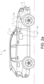
- the vehicle V comprises ADAS sensors 1 and a vehicle driving control system S DC configured for controlling operation of the vehicle V, as shown in figures 2a-b .
- the ADAS sensors 1 are connected to and in communication with the vehicle driving control system S DC via communication cables 2 and configured for sending ADAS sensor output signals Sos to the vehicle driving control system S DC .
- the ADAS sensors 1 are sending relevant information to the vehicle V by the ADAS sensor output signals S OS .
- the ADAS sensor output signals S OS are thus representing information about the surrounding environment, which information is used by the vehicle driving control system S DC when operating the vehicle V.
- Vehicles commonly have a plurality of ADAS sensors used for detecting the surrounding environment.
- the vehicle V comprises two ADAS sensors for illustrative purposes. It should however be understood that the vehicle V may be equipped with, any suitable number of ADAS sensors 1.
- the vehicle driving control system S DC may have different configurations depending on the type of vehicle V.
- the vehicle V is operated in an autonomous driving mode M AU by the vehicle driving control system S DC when activated.
- the vehicle V is operated in a semi-autonomous driving mode M SA with support from the vehicle driving control system S DC when activated.
- the EMC test chamber C further comprises a vehicle dynamometer system 4 in connection to front wheels and rear wheels of the vehicle V.
- the vehicle dynamometer system 4 comprises rollers 5 onto which the vehicle V is positioned.
- the rollers 5 are emulating vehicle inertia and vehicle road load that the vehicle experiences on a real road.
- the vehicle V can be operated in the EMC test chamber C in a way similar to operation in real traffic situations, such as in the autonomous driving mode M AU by the vehicle driving control system S DC or in the semi-autonomous driving mode M SA with support from the vehicle driving control system S DC .
- EMC measurements of the vehicle can be conducted as if the vehicle normally was driven in the outdoor environment, as will be further described below.
- the vehicle dynamometer system 4 may have any suitable configuration, and such systems are well known in the art and are further not described herein.
- the vehicle V may be controlled from outside the EMC test chamber C for operating the vehicle V in the autonomous driving mode M AU by the vehicle driving control system S DC or in the semi-autonomous driving mode M SA with support from the vehicle driving control system S DC .
- the vehicle V may be connected to a non-illustrated control unit or similar device for supporting the operation of the vehicle in the EMC test chamber C in the autonomous driving mode M AU and in the semi-autonomous driving mode M SA .
- the vehicle V may further be equipped with suitable control arrangements for supporting the operation of the vehicle in the EMC test chamber C in the autonomous driving mode M AU or in the semi-autonomous driving mode M SA , enabling operation without test persons seated in the vehicle V.
- the external output unit Uo ⁇ instead of the ADAS sensors 1 arranged on the vehicle V is used for providing ADAS sensor output signals to the vehicle driving control system S DC .
- the ADAS sensors 1 are connected to and in communication with the vehicle driving control system S DC via communication cables 2, as shown in figure 2a .
- the ADAS sensors 1 need to be disconnected from the vehicle driving control system S DC for enabling the external output unit U OE to send synchronized external ADAS sensor output signals S OSE to the vehicle driving control system S DC .
- the communication cables 2 are suitable arranged as a cable bundle arranged for connecting the vehicle driving control system S DC to different ADAS sensors 1 and possibly other components of the vehicle V.
- the communication cables 2 are suitably arranged as fibre optic links.
- the external output unit U OE is configured for being connected to the vehicle driving control system S DC via the communication cables 2.
- the external output unit U OE is connected to the communication cables 2 of the vehicle V via the external communication cables 3, enabling communication between the external output unit U OE and the vehicle driving control system S DC .
- the external communication cables 3 are extending from the external output unit U OE to the vehicle V.
- the communication cables 2 extending from the vehicle driving control system S DC to the ADAS sensors 1 need to be disconnected from the ADAS sensors 1.
- FIGS 2a and 3a the connection between the vehicle driving control system S DC and one of the ADAS sensors 1 via the communication cables 2 are schematically illustrated.
- the communication cables 2 are connected to the ADAS sensors via connectors 6.
- the connectors 6 comprises first connector parts 6a attached to the communication cables 2 and second connector parts 6b attached to the ADAS sensors 1.
- the communication cables 2 are disconnected from the ADAS sensors 1.
- the communication cables 2 are disconnected from the ADAS sensors 1 communication between the ADAS sensors 1 and the vehicle driving control system S DC is prevented, as shown in figure 3b .
- the external communication cables 3 comprises third connector parts 6c configured as corresponding second connector parts 6b, and the third connector parts 6c are configured for being connected to corresponding first connector parts 6a.
- the third connector parts 6c By connecting the third connector parts 6c to corresponding first connector parts 6a communication between the external output unit Uo ⁇ and the vehicle driving control system S DC via the external communication cables 3 and the communication cables 2 is enabled, as shown in figures 2b and 3c .
- the communication cables 2 have been disconnected from the ADAS sensors 1, and instead have been connected to the external output unit Uo ⁇ , communication between the ADAS sensors 1 and the vehicle driving control system S DC is prevented and instead communication between the external output unit Uo ⁇ and the vehicle driving control system S DC is enabled.
- the external output unit U OE is configured for transmitting the synchronized external ADAS sensor output signals S OSE to the vehicle driving control system S DC via the external communication cables 3 and the communication cables 2 upon activation of the vehicle driving control system S DC for operating the vehicle V in the EMC test chamber C during the EMC measuring operation.
- the vehicle V is driven in the EMC test chamber C on the vehicle dynamometer system 4, in a way similar to operation in real traffic situations.
- the synchronized external ADAS sensor output signals Sos ⁇ transmitted to the vehicle driving control system S DC from the external output unit Uo ⁇ are used for imitating the output from the disconnected ADAS sensors 1.
- the synchronized external ADAS sensor output signals S OSE transmitted from the external output unit U OE are thus corresponding to ADAS sensor output signals S OS transmitted from the ADAS sensors 1 to the vehicle driving control system S DC upon operating the vehicle V in real traffic situations.
- synchronized external ADAS sensor output signals Sos ⁇ is meant a set of signals sent from the external output unit U OE to the vehicle driving control system S DC corresponding to combined ADAS sensor output signals Sos from one or more ADAS sensors 1 transmitted to the vehicle driving control system S DC during operation of the vehicle V in real traffic situations.
- the synchronized external ADAS sensor output signals S OSE are suitably configured as recorded synchronized ADAS sensor output signals S OS from real traffic situations.
- a vehicle may thus be operated in real traffic situations and the ADAS sensor output signals Sos are recorded by a recording unit and thereafter used as the synchronized external ADAS sensor output signals Sos ⁇ during the EMC measurement operation.
- the synchronized external ADAS sensor output signals S OSE are configured as simulated synchronized ADAS sensor output signals S OS corresponding to real traffic situations, or configured as a combination of recorded and simulated synchronized ADAS sensor output signals S OS corresponding to real traffic situations.
- the electromagnetic radiation transmitting/receiving unit U TR is used for transmitting electromagnetic radiation into the EMC test chamber C during the vehicle EMC measurement operation.
- the EMC measuring unit U EMC is conducting EMC immunity measurements of the vehicle V upon activation of the vehicle driving control system S DC for operating the vehicle V when the synchronized external ADAS sensor output signals S OSE are transmitted to the vehicle driving control system S DC from the external output unit Uo ⁇ .
- the vehicle V is positioned in the EMC test chamber C with the wheels onto the rollers 5 of the vehicle dynamometer system 4, as understood from figure 1 .
- the communication cables 2 connecting the ADAS sensors 1 to the vehicle driving control system S DC are disconnected from the ADAS sensors 1 for preventing communication between the ADAS sensors 1 and the vehicle driving control system S DC . Thereafter, the communication cables 2 are connected to the external output unit U OE , enabling communication between the external output unit U OE and the vehicle driving control system S DC , as described above in connection to figures 3a-c .
- the vehicle driving control system S DC When the external output unit U OE and the vehicle driving control system S DC are connected to each other via the external communication cables 3 and the communication cables 2, the vehicle driving control system S DC is activated for operating the vehicle V in the EMC test chamber C. Upon activation of the vehicle driving control system S DC , the synchronized external ADAS sensor output signals Sos ⁇ are transmitted from the external output unit Uo ⁇ to the vehicle driving control system S DC via the external communication cables 3 and the communication cables 2. When transmitting the synchronized external ADAS sensor output signals S OSE , the vehicle driving control system S DC is receiving information signals corresponding to ADAS sensor output signals S OS transmitted from the ADAS sensors 1 to the vehicle driving control system S DC upon operating the vehicle V in real traffic situations.
- Electromagnetic radiation is transmitted in the EMC test chamber C by means of the electromagnetic radiation transmitting/receiving unit U TR , and the one or more antennas 7 arranged in the EMC test chamber are sending out the electromagnetic radiation.
- EMC immunity measurements of the vehicle V are conducted by means of the EMC measuring unit U EMC upon activation of the vehicle driving control system S DC for operating the vehicle V when the synchronized external ADAS sensor output signals S OSE are transmitted to the vehicle driving control system S DC from the external output unit U OE .
- the vehicle V is suitably operated in an autonomous driving mode M AU or in a semi-autonomous driving mode M SA , upon activation of the vehicle driving control system S DC .
- the EMC test chamber C is suitably configured as an electromagnetic reverberation chamber or an electromagnetic anechoing chamber.
- the electromagnetic radiation transmitting/receiving unit U TR is used for receiving electromagnetic radiation emitted by the vehicle V into the EMC test chamber C during the vehicle EMC measurement operation.
- the EMC measuring unit U EMC is conducting EMC radiation measurements of the vehicle V upon activation of the vehicle driving control system S DC for operating the vehicle V when the synchronized external ADAS sensor output signals S OSE are transmitted to the vehicle driving control system S DC from the external output unit U OE .
- the vehicle V is positioned in the EMC test chamber C with the wheels onto the rollers 5 of the vehicle dynamometer system 4, as understood from figure 1 .
- the communication cables 2 connecting the ADAS sensors 1 to the vehicle driving control system S DC are disconnected from the ADAS sensors 1 for preventing communication between the ADAS sensors 1 and the vehicle driving control system S DC . Thereafter, the communication cables 2 are connected to the external output unit U OE , enabling communication between the external output unit U OE and the vehicle driving control system S DC , as described above in connection to figures 3a-c .
- the vehicle driving control system S DC When the external output unit U OE and the vehicle driving control system S DC are connected to each other via the external communication cables 3 and the communication cables 2, the vehicle driving control system S DC is activated for operating the vehicle V in the EMC test chamber C.
- the synchronized external ADAS sensor output signals S OSE are transmitted from the external output unit U OE to the vehicle driving control system S DC via the external communication cables 3 and the communication cables 2.
- the vehicle driving control system S DC is receiving information signals corresponding to ADAS sensor output signals Sos transmitted from the ADAS sensors 1 to the vehicle driving control system S DC upon operating the vehicle V in real traffic situations.
- Electromagnetic radiation from the vehicle V in the EMC test chamber C is received by means of the electromagnetic radiation transmitting/receiving unit U TR , and the one or more antennas 7 arranged in the EMC test chamber are receiving the electromagnetic radiation emitted by the vehicle V.
- EMC radiation measurements of the vehicle V are conducted by means of the EMC measuring unit U EMC upon activation of the vehicle driving control system S DC for operating the vehicle V when the synchronized external ADAS sensor output signals Sos ⁇ are transmitted to the vehicle driving control system S DC from the external output unit Uo ⁇ .
- the vehicle V is suitably operated in an autonomous driving mode M AU or in a semi-autonomous driving mode M SA , upon activation of the vehicle driving control system S DC .
- the EMC test chamber C is suitably configured as an electromagnetic reverberation chamber or an electromagnetic anechoing chamber.
- a non-transitory computer-readable storage medium storing one or more programs configured to be executed by one or more processors of the vehicle EMC measurement system S EMC , the one or more programs comprising instructions for performing the method according to any one of the above-discussed embodiments.
- a cloud computing system can be configured to perform any of the method aspects presented herein.
- the cloud computing system may comprise distributed cloud computing resources that jointly perform the method aspects presented herein under control of one or more computer program products.
- the processor may be connected to one or more communication interfaces and/or sensor interfaces for receiving and/transmitting data with external entities such as e.g. sensors arranged on the vehicle surface, an off-site server, or a cloud-based server.
- the processor or processors associated with the vehicle EMC measurement system S EMC may be or include any number of hardware components for conducting data or signal processing or for executing computer code stored in memory.
- the system may have an associated memory, and the memory may be one or more devices for storing data and/or computer code for completing or facilitating the various methods described in the present description.
- the memory may include volatile memory or non-volatile memory.
- the memory may include database components, object code components, script components, or any other type of information structure for supporting the various activities of the present description.
- any distributed or local memory device may be utilized with the systems and methods of this description.
- the memory is communicably connected to the processor (e.g., via a circuit or any other wired, wireless, or network connection) and includes computer code for executing one or more processes described herein.
Landscapes
- Physics & Mathematics (AREA)
- Electromagnetism (AREA)
- General Physics & Mathematics (AREA)
- Traffic Control Systems (AREA)
Abstract
The disclosure concerns a method and EMC measurement system for performing EMC measurements of a complete vehicle. The vehicle comprises ADAS sensors connected to and in communication with a vehicle driving control system configured for controlling operation of the vehicle. The ADAS sensors are configured for sending ADAS sensor output signals to the vehicle driving control system. The vehicle EMC measurement system comprises an EMC test chamber, an electromagnetic radiation transmitting/receiving unit, an external output unit, and an EMC measuring unit. Communication cables from the ADAS sensors are disconnected, preventing communication between the ADAS sensors and the vehicle driving control system, and the communication cables are connected to the external output unit, enabling communication between the external output unit and the vehicle driving control system. The vehicle driving control system is activated for operating the vehicle in the EMC test chamber, and synchronized external ADAS sensor output signals are transmitted from the external output unit to the vehicle driving control system via the communication cables. Electromagnetic radiation is transmitted in the EMC test chamber by means of the electromagnetic radiation transmitting/receiving unit for conducting EMC immunity measurements, or electromagnetic radiation from the vehicle in the EMC test chamber is received by means of the electromagnetic radiation transmitting/receiving unit for conducting EMC radiation measurements.
Description
- The present disclosure relates to a method for performing electromagnetic compatibility (EMC) measurements of a complete vehicle by a vehicle EMC measurement system. The disclosure further relates to a vehicle EMC measurement system, a non-transitory computer-readable medium, and a cloud computing system.
- Electromagnetic compatibility (EMC) measurements and testing operations are aiming at ensuring safe operation of vehicles in the electromagnetic environment to which they may be exposed, or alternatively aiming at understanding the electromagnetic radiation emitted from the vehicles. In order to have controlled and repeatable testing conditions, EMC measurements are commonly conducted in a stationary and screened EMC test chamber.
- The performance of different vehicle systems, such as systems for autonomous driving vehicles or semi-autonomous driving vehicles, may be impacted by strong electromagnetic inference, and the EMC of the vehicle therefore needs to be measured. Further, vehicle systems may emit electromagnetic radiation to the surroundings, and there is a need to measure the emitted electromagnetic radiation.
- It is often difficult to find a suitable outdoor environment to perform the EMC measuring and testing procedures of an autonomous driving vehicle or a semi-autonomous driving vehicle, because the electromagnetic inference in the outdoor environment typically is not strong enough to have a meaningful impact on the software and hardware of the vehicle. Therefore, for the EMC measuring and testing procedures, an indoor EMC testing environment is frequently used, where the electromagnetic inference of a desired level can be artificially established.
- There are however, limitations associated with the indoor EMC testing environment. As an example, an autonomous driving vehicle or a semi-autonomous driving vehicle cannot freely move as it does in the outdoor environment. As a result, the autonomous driving system or the semi-autonomous driving system of the vehicle may need to be modified to accommodate the limitations such that the EMC measurements of the vehicle would be conducted as if the vehicle normally was driven in the outdoor environment.
- The vehicle is using ADAS sensors when operated. When the vehicle is operated in the EMC test chamber during the EMC measurements, the ADAS sensors cannot detect the surrounding environment in the same way as in real traffic situations, since the vehicle in fact is stationary in the EMC test chamber. The ADAS sensors thus have to be manipulated in order for the vehicle to receive relevant ADAS sensor output signals. In some EMC measurement procedures, large image screens, GPS transmitters, and radar targets are used for proving input to the ADAS sensors. Such arrangements are however costly and complex. Further, the input to the ADAS sensors provided by the image screens, GPS transmitters, and radar targets are often not fully corresponding to real traffic situations.
- ADAS systems may detect that the vehicle is stationary and the vehicle may be set into a mode called dyno test mode, which is a mode dedicated for the manufacturers to be able to do certifying tests. The dyno test mode turns off ADAS functionality in order to enable drive simulations in a stationary facility like a vehicle dynamometer, and the dyno test mode makes it impossible to test ADAS functionality without detailed software control over the vehicle drive system, which is difficult to achieve. Further, complete vehicle tests are needed since differences between test setup and vehicle installation differs and may lead to differences to the EMC measurements made.
- There is thus a need for improved EMC measuring and testing procedures for vehicles.
- An object of the present disclosure is to provide a method for performing electromagnetic compatibility (EMC) measurements of a complete vehicle by a vehicle EMC measurement system, a vehicle EMC measurement system, a non-transitory computer-readable medium, and a cloud computing system, where the previously mentioned problems are avoided. This object is at least partly achieved by the features of the independent claims. The dependent claims contain further developments of the method for performing electromagnetic compatibility (EMC) measurements of a complete vehicle by a vehicle EMC measurement system, and the vehicle EMC measurement system.
- The disclosure concerns a method for performing EMC measurements of a complete vehicle by a vehicle EMC measurement system. The vehicle comprises ADAS sensors and a vehicle driving control system configured for controlling operation of the vehicle. The ADAS sensors are connected to and in communication with the vehicle driving control system via communication cables and configured for sending ADAS sensor output signals to the vehicle driving control system. The vehicle EMC measurement system comprises an EMC test chamber, an electromagnetic radiation transmitting/receiving unit, an external output unit, and an EMC measuring unit. The method comprises the steps: providing the complete vehicle and positioning the vehicle in the EMC test chamber; disconnecting the communication cables from the ADAS sensors, preventing communication between the ADAS sensors and the vehicle driving control system; connecting the communication cables to the external output unit, enabling communication between the external output unit and the vehicle driving control system; activating the vehicle driving control system for operating the vehicle in the EMC test chamber, and transmitting synchronized external ADAS sensor output signals from the external output unit to the vehicle driving control system via the communication cables; transmitting electromagnetic radiation in the EMC test chamber by means of the electromagnetic radiation transmitting/receiving unit, and conducting EMC immunity measurements of the vehicle by means of the EMC measuring unit upon activation of the vehicle driving control system for operating the vehicle when the synchronized external ADAS sensor output signals are transmitted to the vehicle driving control system from the external output unit, or receiving electromagnetic radiation from the vehicle in the EMC test chamber by means of the electromagnetic radiation transmitting/receiving unit, and conducting EMC radiation measurements of the vehicle by means of the EMC measuring unit upon activation of the vehicle driving control system for operating the vehicle when the synchronized external ADAS sensor output signals are transmitted to the vehicle driving control system from the external output unit.
- Advantages with these features are that reliable and efficient EMC measurements for a complete vehicle are enabled with the method. The method may be enabled in two different modes for a high flexibility, where either EMC immunity or EMC radiation is measured. By the method, safe operation of vehicles in the electromagnetic environment to which they may be exposed is ensured, and the electromagnetic radiation emitted from the vehicles can be detected. In order to have controlled and repeatable testing conditions, the vehicle EMC measurement system comprises an EMC test chamber. With the method, the vehicle can be operated in the same way as when driven in the outdoor environment during the EMC measurements. Through the ADAS sensor output signals transmitted to the vehicle driving control system from the external output unit, the vehicle is using ADAS sensor information when operated for accurate EMC measurements. This enables maintained ADAS functionality for reliable EMC measurements. The EMC measurement procedures can be made without costly and complex arrangements including large image screens, GPS transmitters, and radar targets.
- In one embodiment, the synchronized external ADAS sensor output signals transmitted from the external output unit are corresponding to ADAS sensor output signals transmitted from the ADAS sensors to the vehicle driving control system upon operating the vehicle in real traffic situations. In this way, the vehicle can be operated in the same way as in real traffic situations for accurate EMC measurements. The vehicle driving control system is thus receiving the same type of signals in the EMC test chamber, as when operating the vehicle in real traffic situations.
- In one embodiment, the synchronized external ADAS sensor output signals are recorded synchronized ADAS sensor output signals from real traffic situations, and/or the synchronized external ADAS sensor output signals are simulated synchronized ADAS sensor output signals corresponding to real traffic situations. The synchronized external ADAS sensor output signals can be configured as recorded synchronized ADAS sensor output signals from real traffic situations. A vehicle may thus be operated in real traffic situations and the ADAS sensor output signals are recorded by a recording unit and thereafter used as the synchronized external ADAS sensor output signals during the EMC measurement operation. Alternatively, the synchronized external ADAS sensor output signals are configured as simulated synchronized ADAS sensor output signals corresponding to real traffic situations. Further, the synchronized external ADAS sensor output signals may be configured as a combination of recorded and simulated synchronized ADAS sensor output signals corresponding to real traffic situations.
- In one embodiment, the method further comprises the steps: operating the vehicle in an autonomous driving mode or operating the vehicle in a semi-autonomous driving mode, upon activation of the vehicle driving control system. With these operational modes, the vehicle is using the ADAS sensor signals for reliable EMC measurements.
- In one embodiment, the external output unit is arranged in a position outside the EMC test chamber. External communication cables connected to the external output unit are extending from the external output unit to the vehicle. The method further comprises the step: connecting the external output unit to the communication cables of the vehicle via the external communication cables for enabling communication between the external output unit and the vehicle driving control system. The position of the external output unit outside the EMC test chamber is allowing test operators to control the EMC measurements efficiently without disturbing the measurements in the EMC test chamber.
- In one embodiment, the external communication cables are arranged as fibre optic links. The fibre optic links are efficiently transmitting the external ADAS sensor output signals from the external output unit.
- In one embodiment, the EMC test chamber is configured as an electromagnetic reverberation chamber or an electromagnetic anechoing chamber. The EMC test chamber may have any suitable configuration, and the EMC test chamber is suitably arranged as an electromagnetic reverberation chamber or an electromagnetic anechoing chamber. The measurement and test equipment used in the EMC test chamber is adapted to the type of EMC test chamber used. An electromagnetic anechoic chamber is a room designed to stop reflections of electromagnetic waves, and are commonly isolated from energy entering from the surroundings. An electromagnetic reverberation chamber is an environment for EMC measurements arranged as a screened room with a minimum of absorption of electromagnetic energy.
- In one embodiment, the steps of: activating the vehicle driving control system, and transmitting synchronized external ADAS sensor output signals from the external output unit to the vehicle driving control system via the communication cables; and transmitting electromagnetic radiation in the EMC test chamber by means of the electromagnetic radiation transmitting/receiving unit, and conducting EMC immunity measurements of the vehicle by means of the EMC measuring unit upon activation of the vehicle driving control system for operating the vehicle when the synchronized external ADAS sensor output signals are transmitted to the vehicle driving control system from the external output unit; are computer implemented. In an alternative embodiment, the steps of: activating the vehicle driving control system, and transmitting synchronized external ADAS sensor output signals from the external output unit to the vehicle driving control system via the communication cables; and receiving electromagnetic radiation from the vehicle in the EMC test chamber by means of the electromagnetic radiation transmitting/receiving unit, and conducting EMC radiation measurements of the vehicle by means of the EMC measuring unit upon activation of the vehicle driving control system for operating the vehicle when the synchronized external ADAS sensor output signals are transmitted to the vehicle driving control system from the external output unit; are computer implemented.
- The disclosure further concerns a vehicle EMC measurement system comprising an EMC test chamber, an electromagnetic radiation transmitting/receiving unit, an external output unit, and an EMC measuring unit. The vehicle EMC measurement system is arranged for measuring EMC of a complete vehicle positioned in the EMC test chamber. The vehicle comprises ADAS sensors and a vehicle driving control system configured for controlling operation of the vehicle. The ADAS sensors are connected to and in communication with the vehicle driving control system via communication cables and configured for sending ADAS sensor output signals to the vehicle driving control system. The external output unit is configured for being connected to the vehicle driving control system via the communication cables, enabling communication between the external output unit and the vehicle driving control system, when the communication cables are disconnected from the ADAS sensors, preventing communication between the ADAS sensors and the vehicle driving control system. The external output unit is configured for transmitting synchronized external ADAS sensor output signals to the vehicle driving control system via the communication cables upon activation of the vehicle driving control system for operating the vehicle in the EMC test chamber. The electromagnetic radiation transmitting/receiving unit is configured for transmitting electromagnetic radiation in the EMC test chamber, and the EMC measuring unit is configured for conducting EMC immunity measurements of the vehicle upon activation of the vehicle driving control system for operating the vehicle when the synchronized external ADAS sensor output signals are transmitted to the vehicle driving control system from the external output unit; or the electromagnetic radiation transmitting/receiving unit is configured for receiving electromagnetic radiation from the vehicle in the EMC test chamber, and the EMC measuring unit is configured for conducting EMC radiation measurements of the vehicle upon activation of the vehicle driving control system for operating the vehicle when the synchronized external ADAS sensor output signals are transmitted to the vehicle driving control system from the external output unit.
- Advantages with these features are that reliable and efficient EMC measurements for a complete vehicle are enabled with the system. The system may be operated in two different modes for a high flexibility, where either EMC immunity or EMC radiation is measured. With the system, safe operation of vehicles in the electromagnetic environment to which they may be exposed is ensured, and the electromagnetic radiation emitted from the vehicles can be detected. In order to have controlled and repeatable testing conditions, the vehicle EMC measurement system comprises an EMC test chamber. With the system, the vehicle can be operated in the same way as when driven in the outdoor environment during the EMC measurements. Through the ADAS sensor output signals transmitted to the vehicle driving control system from the external output unit, the vehicle is using ADAS sensor information when operated for accurate EMC measurements, which enables maintained ADAS functionality for reliable EMC measurements. The EMC measurement procedures can be made without costly and complex arrangements including large image screens, GPS transmitters, and radar targets.
- In one embodiment, the synchronized external ADAS sensor output signals transmitted from the external output unit are corresponding to ADAS sensor output signals transmitted from the ADAS sensors to the vehicle driving control system upon operating the vehicle in real traffic situations. In this way, the vehicle can be operated in the same way as in real traffic situations for accurate EMC measurements. The vehicle driving control system is thus receiving the same type of signals in the EMC test chamber, as when operating the vehicle in real traffic situations.
- In one embodiment, the synchronized external ADAS sensor output signals are recorded synchronized ADAS sensor output signals from real traffic situations, and/or the synchronized external ADAS sensor output signals are simulated synchronized ADAS sensor output signals corresponding to real traffic situations. The synchronized external ADAS sensor output signals can be configured as recorded synchronized ADAS sensor output signals from real traffic situations. A vehicle may thus be operated in real traffic situations and the ADAS sensor output signals are recorded by a recording unit and thereafter used as the synchronized external ADAS sensor output signals during the EMC measurement operation. Alternatively, the synchronized external ADAS sensor output signals are configured as simulated synchronized ADAS sensor output signals corresponding to real traffic situations. Further, the synchronized external ADAS sensor output signals may be configured as a combination of recorded and simulated synchronized ADAS sensor output signals corresponding to real traffic situations.
- In one embodiment, the vehicle is operated in an autonomous driving mode or in a semi-autonomous driving mode, upon activation of the vehicle driving control system. With these operational modes, the vehicle is using the ADAS sensor signals for reliable EMC measurements.
- In one embodiment, the external output unit is arranged in a position outside the EMC test chamber. External communication cables connected to the external output unit are extending from the external output unit to the vehicle. The external output unit is connected to the communication cables of the vehicle via the external communication cables, enabling communication between the external output unit and the vehicle driving control system. The position of the external output unit outside the EMC test chamber is allowing test operators to control the EMC measurements efficiently without disturbing the measurements in the EMC test chamber.
- In one embodiment, the external communication cables are arranged as fibre optic links. The fibre optic links are efficiently transmitting the external ADAS sensor output signals from the external output unit.
- In one embodiment, the EMC test chamber is configured as an electromagnetic reverberation chamber or an electromagnetic anechoing chamber. The EMC test chamber may have any suitable configuration, and the EMC test chamber is suitably arranged as an electromagnetic reverberation chamber or an electromagnetic anechoing chamber. The measurement and test equipment used in the EMC test chamber is adapted to the type of EMC test chamber used. An electromagnetic anechoic chamber is a room designed to stop reflections of electromagnetic waves, and are commonly isolated from energy entering from the surroundings. An electromagnetic reverberation chamber is an environment for EMC measurements arranged as a screened room with a minimum of absorption of electromagnetic energy.
- In one embodiment, the electromagnetic radiation transmitting/receiving unit comprises one or more antennas arranged in the EMC test chamber, wherein the one or more antennas are configured for transmitting and/or receiving electromagnetic radiation in the EMC test chamber.
- The disclosure further concerns a non-transitory computer-readable medium comprising instructions which, when executed by a computer, cause the computer to carry out the method.
- The disclosure further concerns a cloud computing system configured to carry out the method.
- The disclosure will be described in detail in the following, with reference to the attached drawings, in which
- Fig. 1
- shows schematically, in a perspective view, a vehicle EMC measurement system with a complete vehicle positioned in an EMC test chamber, according to the disclosure,
- Fig. 2a-b
- show schematically, in side views, the complete vehicle with a vehicle driving control system connected to ADAS sensors, and the complete vehicle with the vehicle driving control system disconnected from the ADAS sensors and connected to an external output unit, according to the disclosure,
- Fig. 3a-c
- shows schematically, in operational views, the vehicle driving control system connected to the ADAS sensors, the vehicle driving control system disconnected from the ADAS sensors, and the vehicle driving control system connected to the external output unit.
- Various aspects of the disclosure will hereinafter be described in conjunction with the appended drawings to illustrate and not to limit the disclosure, wherein like designations denote like elements, and variations of the described aspects are not restricted to the specifically shown embodiments, but are applicable on other variations of the disclosure.
- Those skilled in the art will appreciate that steps, services and functions explained herein may be implemented using individual hardware circuitry, using software functioning in conjunction with a programmed microprocessor or general purpose computer, using one or more Application Specific Integrated Circuits (ASICs) and/or using one or more Digital Signal Processors (DSPs). It will also be appreciated that when the present disclosure is described in terms of a method, it may also be embodied in one or more processors and one or more memories coupled to the one or more processors, wherein the one or more memories store one or more programs that perform the steps, services and functions disclosed herein when executed by the one or more processors.
-
Figure 1 schematically shows an electromagnetic compatibility (EMC) measurement system SEMC. The EMC measurement system SEMC is used for performing EMC measurement and testing operations of a complete vehicle V. The vehicle EMC measurement system SEMC comprises an EMC test chamber C, an electromagnetic radiation transmitting/receiving unit UTR, an external output unit UOE, and an EMC measuring unit UEMC. The complete vehicle V is as understood from the figure arranged in the EMC test chamber C. - EMC measurements and testing operations are aiming at ensuring safe operation of vehicles in the electromagnetic environment to which they may be exposed, or alternatively aiming at understanding the electromagnetic radiation emitted from the vehicles. In order to have controlled and repeatable testing conditions, EMC measurements are commonly conducted in a stationary and screened EMC test chamber.
- The performance of different vehicle systems may be impacted by strong electromagnetic inference, and the EMC of the vehicle therefore needs to be measured. EMC is the ability of electrical equipment and systems to function acceptably in their electromagnetic environment, and there is a need for measuring the functionality of individual vehicle components as well as the complete vehicle to secure reliable operation of the vehicle in operating conditions of the vehicle. To comply with government regulations and legal requirements, and to ensure the safety of the vehicle, the vehicle needs to go through EMC measurement procedures. It is in the EMC measuring procedures measured and tested how software and hardware in the vehicle are impacted in an EMC testing environment. The EMC testing environment is established in the EMC test chamber C.
- The EMC testing procedure is used for determining if actions related to limiting unintentional generation, propagation and reception of electromagnetic energy that may cause unwanted effects, such as electromagnetic interference, or even damage in operational equipment is needed. The goal of the EMC testing procedure is to determine the correct operation of different equipment in a common electromagnetic environment.
- Vehicles operating in an autonomous driving mode or a semi-autonomous driving mode can relieve a driver of the vehicle from certain driving-related responsibilities. When operating in the autonomous driving mode or the semi-autonomous driving mode, the vehicle is using autonomous drive functions, and sensors arranged on the vehicle allow the vehicle to travel with less human interaction.
- Autonomous driving vehicles and semi-autonomous driving vehicles use autonomous driving systems to drive the vehicle, and the autonomous driving system can include software and hardware. Such a system related to the driving of the vehicles are commonly named advanced driver-assistance system (ADAS). ADAS is using groups of automated technology and electronic equipment that assist drivers in driving the vehicle, and as an example, the system uses ADAS sensors to detect the surrounding environment. By the ADAS sensors, the system may detect nearby obstacles or driver errors and responds accordingly. ADAS can enable various levels of autonomous driving, depending on the type of systems installed in the vehicle. ADAS sensors may have different configurations, such as optical image sensors, sonar sensors, radar sensors, LIDAR sensors and GPS/GNSS sensors. Optical image sensors may be arranged as camera or video sensors. Sonar is referring to sound navigation and ranging, and sonar sensors may be arranged as ultrasonic sensors. Radar is referring to radio detection and ranging, and radar sensors are using specific radio frequencies to detect objects. LIDAR is referring to light detection and ranging, and LIDAR sensors use lasers as energy source. GNSS is a global navigation satellite system used for vehicle navigation. GPS stands for global positioning system and is a GNSS that uses satellites for navigating purposes. It should be understood that ADAS sensors could have other configurations than the ones described above, for example ADAS sensors arranged for communication between vehicles and/or communication between vehicles and surrounding infrastructure, such as V2X (DSRC) and/or C-V2X (4G/5G).
- It is often difficult to find a suitable outdoor environment to perform the EMC measuring and testing procedures of an autonomous driving vehicle or a semi-autonomous driving vehicle, because the electromagnetic inference in the outdoor environment typically is not strong enough to have a meaningful impact on the software and hardware of the vehicle. Therefore, for the EMC measuring and testing procedures, the vehicle EMC measurement system SEMC is used, where the electromagnetic inference of a desired level can be artificially established or detected.
- The EMC test chamber C may have any suitable configuration, and the EMC test chamber C is commonly arranged as an electromagnetic reverberation chamber or an electromagnetic anechoing chamber. The measurement and test equipment used in the EMC test chamber C is adapted to the type of EMC test chamber C used. In
figure 1 , the EMC test chamber C is configured as an electromagnetic anechoing chamber for illustrative purposes. - An electromagnetic anechoic chamber is a room designed to stop reflections of electromagnetic waves, and are commonly isolated from energy entering from the surroundings. An electromagnetic reverberation chamber is an environment for EMC measurements arranged as a screened room with a minimum of absorption of electromagnetic energy. These general types of EMC test chambers are known in the art and will not be described more in detail. It should however be understood that the EMC test chamber C may have other suitable designs and configurations.
- The vehicle EMC measurement system SEMC is arranged for measuring EMC of a complete vehicle V positioned in the EMC test chamber C. With the expression complete vehicle is meant a vehicle equipped with relevant components and systems, such as a vehicle approved for being operated in normal traffic conditions. The complete vehicle V is thus an assembled vehicle, and not individual vehicle components or vehicle systems. In this context when it is referred to a vehicle, the expression vehicle should be interpreted as a complete vehicle.
- The vehicle EMC measurement system SEMC may be operated in different modes, depending on the measurements conducted. In an EMC immunity mode MI, EMC immunity measurements of the vehicle V are conducted in order to determine safe operation of the vehicle V in the electromagnetic environment to which the vehicle V may be exposed. In an EMC radiation mode MR, EMC radiation measurements are conducted in order to determine the electromagnetic radiation emitted from the vehicle V.
- In the EMC immunity mode MI, the electromagnetic radiation transmitting/receiving unit UTR is arranged inside the EMC test chamber C, as shown in
figure 1 . The electromagnetic radiation transmitting/receiving unit UTR is used for transmitting electromagnetic radiation into the EMC test chamber C when the vehicle EMC measurement system SEMC is operated in the EMC immunity mode MI. The electromagnetic radiation transmitting/receiving unit UTR suitably comprises one ormore antennas 7 arranged in the EMC test chamber C. The one ormore antennas 7 are used for transmitting the electromagnetic radiation in the EMC test chamber C. - In the EMC radiation mode MR, the electromagnetic radiation transmitting/receiving unit UTR is arranged inside the EMC test chamber C, as shown in
figure 1 . The electromagnetic radiation transmitting/receiving unit UTR is used for receiving electromagnetic radiation emitted by the vehicle V into the EMC test chamber C when the vehicle EMC measurement system SEMC is operated in the EMC radiation mode MR. The electromagnetic radiation transmitting/receiving unit UTR suitably comprises one ormore antennas 7 arranged in the EMC test chamber C. The one ormore antennas 7 are used for receiving electromagnetic radiation in the EMC test chamber C emitted by the vehicle V. It should be understood that the one ormore antennas 7 used for receiving electromagnetic radiation in the EMC test chamber C emitted by the vehicle V may be different from the one ormore antennas 7 used for transmitting the electromagnetic radiation in the EMC test chamber C in the ECM immunity measurements. - The external output unit Uoε is arranged in a position outside the EMC test chamber C, as shown in
figure 1 . The external output unit UOE is suitably arranged as a computer system that is used for providing signals to the vehicle V during the EMC measurement operation.External communication cables 3 are connected to the external output unit UOE, and as understood from the figure, theexternal communication cables 3 are extending from the external output unit UOE to the vehicle V. Theexternal communication cables 3 are suitable arranged as a cable bundle arranged for being attached to different ADAS sensor connectors of the vehicle V. Suitably, theexternal communication cables 3 are arranged as fibre optic links. - The EMC measuring unit UEMC may be configured in different ways depending on the measurements made, and depending on the operating mode of the vehicle EMC measurement system SEMC.
- In the EMC immunity mode MI, the EMC measuring unit UEMC suitably is arranged as one or more sensors for determining if different vehicle systems are impacted by strong electromagnetic inference. In one embodiment, the EMC measuring unit UEMC is configured as a camera sensor arranged in the vehicle V, as schematically illustrated in
figure 1 , and the camera sensor is used for determining if the vehicle systems are functioning when the electromagnetic radiation transmitting/receiving unit UTR is transmitting electromagnetic radiation into the EMC test chamber C. The camera sensor may be externally monitored or observed by test persons outside the EMC test chamber C, and by monitoring or observing different vehicle systems, it may be determined if the vehicle systems are operating as they should. In one standard procedure, the wipers and the position lights of the vehicle V are operated and during the operations, different vehicle systems, such as dashboard indicators, vehicle screens and other equipment, are observed by test persons via the camera sensor. In other embodiments, the EMC measuring unit UEMC is configured as one or more sensors arranged in the vehicle for determining the functionality of different vehicle systems, such as sensors connected to different vehicle systems or equipment. - In the EMC radiation mode MR, the EMC measuring unit UEMC suitably is arranged as a measuring unit operating together with the electromagnetic radiation transmitting/receiving unit UTR for detecting the level of electromagnetic radiation emitted from the vehicle V during the EMC measuring operation. In one embodiment, the EMC measuring unit UEMC is connected to the one or
more antennas 7 arranged in the EMC test chamber C. - The vehicle V comprises
ADAS sensors 1 and a vehicle driving control system SDC configured for controlling operation of the vehicle V, as shown infigures 2a-b . TheADAS sensors 1 are connected to and in communication with the vehicle driving control system SDC viacommunication cables 2 and configured for sending ADAS sensor output signals Sos to the vehicle driving control system SDC. During normal operation of the vehicle V, such as when operating the vehicle V in real traffic situations, theADAS sensors 1 are sending relevant information to the vehicle V by the ADAS sensor output signals SOS. The ADAS sensor output signals SOS are thus representing information about the surrounding environment, which information is used by the vehicle driving control system SDC when operating the vehicle V. Vehicles commonly have a plurality of ADAS sensors used for detecting the surrounding environment. In the embodiment shown in the figures, the vehicle V comprises two ADAS sensors for illustrative purposes. It should however be understood that the vehicle V may be equipped with, any suitable number ofADAS sensors 1. - The vehicle driving control system SDC may have different configurations depending on the type of vehicle V. In one embodiment, the vehicle V is operated in an autonomous driving mode MAU by the vehicle driving control system SDC when activated. In one embodiment, the vehicle V is operated in a semi-autonomous driving mode MSA with support from the vehicle driving control system SDC when activated.
- There are limitations associated with the indoor EMC testing environment, since the vehicle V cannot freely move as it does in the outdoor environment. Therefore, the driving operation of the vehicle V needs to be efficiently controlled. As shown in
figure 1 , the EMC test chamber C further comprises a vehicle dynamometer system 4 in connection to front wheels and rear wheels of the vehicle V. The vehicle dynamometer system 4 comprisesrollers 5 onto which the vehicle V is positioned. Therollers 5 are emulating vehicle inertia and vehicle road load that the vehicle experiences on a real road. By using the vehicle dynamometer system 4, the vehicle V can be operated in the EMC test chamber C in a way similar to operation in real traffic situations, such as in the autonomous driving mode MAU by the vehicle driving control system SDC or in the semi-autonomous driving mode MSA with support from the vehicle driving control system SDC. As a result, EMC measurements of the vehicle can be conducted as if the vehicle normally was driven in the outdoor environment, as will be further described below. The vehicle dynamometer system 4 may have any suitable configuration, and such systems are well known in the art and are further not described herein. - In the EMC test chamber C, the vehicle V may be controlled from outside the EMC test chamber C for operating the vehicle V in the autonomous driving mode MAU by the vehicle driving control system SDC or in the semi-autonomous driving mode MSA with support from the vehicle driving control system SDC. Thus, the vehicle V may be connected to a non-illustrated control unit or similar device for supporting the operation of the vehicle in the EMC test chamber C in the autonomous driving mode MAU and in the semi-autonomous driving mode MSA. The vehicle V may further be equipped with suitable control arrangements for supporting the operation of the vehicle in the EMC test chamber C in the autonomous driving mode MAU or in the semi-autonomous driving mode MSA, enabling operation without test persons seated in the vehicle V.
- When the vehicle is operated in the EMC test chamber C, the
ADAS sensors 1 cannot detect the surrounding environment in the same way as in real traffic situations, since the vehicle V in fact is stationary in the EMC test chamber C. According the disclosure, the external output unit Uoε instead of theADAS sensors 1 arranged on the vehicle V is used for providing ADAS sensor output signals to the vehicle driving control system SDC. TheADAS sensors 1 are connected to and in communication with the vehicle driving control system SDC viacommunication cables 2, as shown infigure 2a . TheADAS sensors 1 need to be disconnected from the vehicle driving control system SDC for enabling the external output unit UOE to send synchronized external ADAS sensor output signals SOSE to the vehicle driving control system SDC. Thecommunication cables 2 are suitable arranged as a cable bundle arranged for connecting the vehicle driving control system SDC todifferent ADAS sensors 1 and possibly other components of the vehicle V. Thecommunication cables 2 are suitably arranged as fibre optic links. - The external output unit UOE is configured for being connected to the vehicle driving control system SDC via the
communication cables 2. The external output unit UOE is connected to thecommunication cables 2 of the vehicle V via theexternal communication cables 3, enabling communication between the external output unit UOE and the vehicle driving control system SDC. As described above, theexternal communication cables 3 are extending from the external output unit UOE to the vehicle V. - To connect the external output unit UOE to the vehicle V, the
communication cables 2 extending from the vehicle driving control system SDC to theADAS sensors 1 need to be disconnected from theADAS sensors 1. Infigures 2a and3a , the connection between the vehicle driving control system SDC and one of theADAS sensors 1 via thecommunication cables 2 are schematically illustrated. As shown in the figures, thecommunication cables 2 are connected to the ADAS sensors viaconnectors 6. Theconnectors 6 comprisesfirst connector parts 6a attached to thecommunication cables 2 andsecond connector parts 6b attached to theADAS sensors 1. - By disconnecting the
first connector parts 6a from thesecond connector parts 6b, thecommunication cables 2 are disconnected from theADAS sensors 1. When thecommunication cables 2 are disconnected from theADAS sensors 1 communication between theADAS sensors 1 and the vehicle driving control system SDC is prevented, as shown infigure 3b . - The
external communication cables 3 comprisesthird connector parts 6c configured as correspondingsecond connector parts 6b, and thethird connector parts 6c are configured for being connected to correspondingfirst connector parts 6a. By connecting thethird connector parts 6c to correspondingfirst connector parts 6a communication between the external output unit Uoε and the vehicle driving control system SDC via theexternal communication cables 3 and thecommunication cables 2 is enabled, as shown infigures 2b and3c . Thus, when thecommunication cables 2 have been disconnected from theADAS sensors 1, and instead have been connected to the external output unit Uoε, communication between theADAS sensors 1 and the vehicle driving control system SDC is prevented and instead communication between the external output unit Uoε and the vehicle driving control system SDC is enabled. - It should be understood that the connector parts could have different configurations for
different ADAS sensors 1. - The external output unit UOE is configured for transmitting the synchronized external ADAS sensor output signals SOSE to the vehicle driving control system SDC via the
external communication cables 3 and thecommunication cables 2 upon activation of the vehicle driving control system SDC for operating the vehicle V in the EMC test chamber C during the EMC measuring operation. When operating the vehicle V in the EMC test chamber C during the EMC measuring operation, the vehicle V is driven in the EMC test chamber C on the vehicle dynamometer system 4, in a way similar to operation in real traffic situations. Instead of detecting the surrounding environment by means of theADAS sensors 1, the synchronized external ADAS sensor output signals Sosε transmitted to the vehicle driving control system SDC from the external output unit Uoε are used for imitating the output from thedisconnected ADAS sensors 1. The synchronized external ADAS sensor output signals SOSE transmitted from the external output unit UOE are thus corresponding to ADAS sensor output signals SOS transmitted from theADAS sensors 1 to the vehicle driving control system SDC upon operating the vehicle V in real traffic situations. By the expression synchronized external ADAS sensor output signals Sosε is meant a set of signals sent from the external output unit UOE to the vehicle driving control system SDC corresponding to combined ADAS sensor output signals Sos from one ormore ADAS sensors 1 transmitted to the vehicle driving control system SDC during operation of the vehicle V in real traffic situations. - The synchronized external ADAS sensor output signals SOSE are suitably configured as recorded synchronized ADAS sensor output signals SOS from real traffic situations. A vehicle may thus be operated in real traffic situations and the ADAS sensor output signals Sos are recorded by a recording unit and thereafter used as the synchronized external ADAS sensor output signals Sosε during the EMC measurement operation. Alternatively, the synchronized external ADAS sensor output signals SOSE are configured as simulated synchronized ADAS sensor output signals SOS corresponding to real traffic situations, or configured as a combination of recorded and simulated synchronized ADAS sensor output signals SOS corresponding to real traffic situations. In the EMC immunity mode MI, the electromagnetic radiation transmitting/receiving unit UTR is used for transmitting electromagnetic radiation into the EMC test chamber C during the vehicle EMC measurement operation.
- Further, in the EMC immunity mode MI, the EMC measuring unit UEMC is conducting EMC immunity measurements of the vehicle V upon activation of the vehicle driving control system SDC for operating the vehicle V when the synchronized external ADAS sensor output signals SOSE are transmitted to the vehicle driving control system SDC from the external output unit Uoε.
- To perform immunity EMC measurements of the complete vehicle V by the vehicle EMC measurement system SEMC in the EMC immunity mode MI, the vehicle V is positioned in the EMC test chamber C with the wheels onto the
rollers 5 of the vehicle dynamometer system 4, as understood fromfigure 1 . Thecommunication cables 2 connecting theADAS sensors 1 to the vehicle driving control system SDC, are disconnected from theADAS sensors 1 for preventing communication between theADAS sensors 1 and the vehicle driving control system SDC. Thereafter, thecommunication cables 2 are connected to the external output unit UOE, enabling communication between the external output unit UOE and the vehicle driving control system SDC, as described above in connection tofigures 3a-c . When the external output unit UOE and the vehicle driving control system SDC are connected to each other via theexternal communication cables 3 and thecommunication cables 2, the vehicle driving control system SDC is activated for operating the vehicle V in the EMC test chamber C. Upon activation of the vehicle driving control system SDC, the synchronized external ADAS sensor output signals Sosε are transmitted from the external output unit Uoε to the vehicle driving control system SDC via theexternal communication cables 3 and thecommunication cables 2. When transmitting the synchronized external ADAS sensor output signals SOSE, the vehicle driving control system SDC is receiving information signals corresponding to ADAS sensor output signals SOS transmitted from theADAS sensors 1 to the vehicle driving control system SDC upon operating the vehicle V in real traffic situations. Electromagnetic radiation is transmitted in the EMC test chamber C by means of the electromagnetic radiation transmitting/receiving unit UTR, and the one ormore antennas 7 arranged in the EMC test chamber are sending out the electromagnetic radiation. When the electromagnetic radiation is transmitted in the EMC test chamber C by means of the electromagnetic radiation transmitting/receiving unit UTR, EMC immunity measurements of the vehicle V are conducted by means of the EMC measuring unit UEMC upon activation of the vehicle driving control system SDC for operating the vehicle V when the synchronized external ADAS sensor output signals SOSE are transmitted to the vehicle driving control system SDC from the external output unit UOE. The vehicle V is suitably operated in an autonomous driving mode MAU or in a semi-autonomous driving mode MSA, upon activation of the vehicle driving control system SDC. Further, the EMC test chamber C is suitably configured as an electromagnetic reverberation chamber or an electromagnetic anechoing chamber. - In the EMC immunity mode MI, the steps of: activating the vehicle driving control system SDC, and transmitting synchronized external ADAS sensor output signals SOSE from the external output unit Uoε to the vehicle driving control system SDC via the
communication cables 2; and transmitting electromagnetic radiation in the EMC test chamber C by means of the electromagnetic radiation transmitting/receiving unit UTR, and conducting EMC immunity measurements of the vehicle V by means of the EMC measuring unit UEMC upon activation of the vehicle driving control system SDC for operating the vehicle V when the synchronized external ADAS sensor output signals SOSE are transmitted to the vehicle driving control system SDC from the external output unit UOE; are suitably computer implemented. - In the EMC radiation mode MR, the electromagnetic radiation transmitting/receiving unit UTR is used for receiving electromagnetic radiation emitted by the vehicle V into the EMC test chamber C during the vehicle EMC measurement operation.
- Further, in the EMC radiation mode MR, the EMC measuring unit UEMC is conducting EMC radiation measurements of the vehicle V upon activation of the vehicle driving control system SDC for operating the vehicle V when the synchronized external ADAS sensor output signals SOSE are transmitted to the vehicle driving control system SDC from the external output unit UOE.
- To perform radiation EMC measurements of the complete vehicle V by the vehicle EMC measurement system SEMC in the EMC radiation mode MR, the vehicle V is positioned in the EMC test chamber C with the wheels onto the
rollers 5 of the vehicle dynamometer system 4, as understood fromfigure 1 . Thecommunication cables 2 connecting theADAS sensors 1 to the vehicle driving control system SDC are disconnected from theADAS sensors 1 for preventing communication between theADAS sensors 1 and the vehicle driving control system SDC. Thereafter, thecommunication cables 2 are connected to the external output unit UOE, enabling communication between the external output unit UOE and the vehicle driving control system SDC, as described above in connection tofigures 3a-c . When the external output unit UOE and the vehicle driving control system SDC are connected to each other via theexternal communication cables 3 and thecommunication cables 2, the vehicle driving control system SDC is activated for operating the vehicle V in the EMC test chamber C. Upon activation of the vehicle driving control system SDC, the synchronized external ADAS sensor output signals SOSE are transmitted from the external output unit UOE to the vehicle driving control system SDC via theexternal communication cables 3 and thecommunication cables 2. When transmitting the synchronized external ADAS sensor output signals SOSE, the vehicle driving control system SDC is receiving information signals corresponding to ADAS sensor output signals Sos transmitted from theADAS sensors 1 to the vehicle driving control system SDC upon operating the vehicle V in real traffic situations. Electromagnetic radiation from the vehicle V in the EMC test chamber C is received by means of the electromagnetic radiation transmitting/receiving unit UTR, and the one ormore antennas 7 arranged in the EMC test chamber are receiving the electromagnetic radiation emitted by the vehicle V. When the electromagnetic radiation emitted from the vehicle V is received in the EMC test chamber C by means of the electromagnetic radiation transmitting/receiving unit UTR, EMC radiation measurements of the vehicle V are conducted by means of the EMC measuring unit UEMC upon activation of the vehicle driving control system SDC for operating the vehicle V when the synchronized external ADAS sensor output signals Sosε are transmitted to the vehicle driving control system SDC from the external output unit Uoε. The vehicle V is suitably operated in an autonomous driving mode MAU or in a semi-autonomous driving mode MSA, upon activation of the vehicle driving control system SDC. Further, the EMC test chamber C is suitably configured as an electromagnetic reverberation chamber or an electromagnetic anechoing chamber. - In the EMC radiation mode MR, the steps of: activating the vehicle driving control system SDC, and transmitting synchronized external ADAS sensor output signals Sosε from the external output unit Uoε to the vehicle driving control system SDC via the
communication cables 2; and receiving electromagnetic radiation from the vehicle V in the EMC test chamber C by means of the electromagnetic radiation transmitting/receiving unit UTR, and conducting EMC radiation measurements of the vehicle V by means of the EMC measuring unit UEMC upon activation of the vehicle driving control system SDC for operating the vehicle V when the synchronized external ADAS sensor output signals Sosε are transmitted to the vehicle driving control system SDC from the external output unit Uoε; are suitably computer implemented. - The present disclosure has been presented above with reference to specific embodiments. However, other embodiments than the above described are possible and within the scope of the disclosure. Different method steps than those described above, performing the method by hardware or software, may be provided within the scope of the disclosure. Thus, according to an exemplary embodiment, there is provided a non-transitory computer-readable storage medium storing one or more programs configured to be executed by one or more processors of the vehicle EMC measurement system SEMC, the one or more programs comprising instructions for performing the method according to any one of the above-discussed embodiments. Alternatively, according to another exemplary embodiment a cloud computing system can be configured to perform any of the method aspects presented herein. The cloud computing system may comprise distributed cloud computing resources that jointly perform the method aspects presented herein under control of one or more computer program products. Moreover, the processor may be connected to one or more communication interfaces and/or sensor interfaces for receiving and/transmitting data with external entities such as e.g. sensors arranged on the vehicle surface, an off-site server, or a cloud-based server.
- The processor or processors associated with the vehicle EMC measurement system SEMC may be or include any number of hardware components for conducting data or signal processing or for executing computer code stored in memory. The system may have an associated memory, and the memory may be one or more devices for storing data and/or computer code for completing or facilitating the various methods described in the present description. The memory may include volatile memory or non-volatile memory. The memory may include database components, object code components, script components, or any other type of information structure for supporting the various activities of the present description. According to an exemplary embodiment, any distributed or local memory device may be utilized with the systems and methods of this description. According to an exemplary embodiment the memory is communicably connected to the processor (e.g., via a circuit or any other wired, wireless, or network connection) and includes computer code for executing one or more processes described herein.
- It will be appreciated that the above description is merely exemplary in nature and is not intended to limit the present disclosure, its application or uses. While specific examples have been described in the specification and illustrated in the drawings, it will be understood by those of ordinary skill in the art that various changes may be made and equivalents may be substituted for elements thereof without departing from the scope of the present disclosure as defined in the claims. Furthermore, modifications may be made to adapt a particular situation or material to the teachings of the present disclosure without departing from the essential scope thereof. Therefore, it is intended that the present disclosure not be limited to the particular examples illustrated by the drawings and described in the specification as the best mode presently contemplated for carrying out the teachings of the present disclosure, but that the scope of the present disclosure will include any embodiments falling within the foregoing description and the appended claims. Reference signs mentioned in the claims should not be seen as limiting the extent of the matter protected by the claims, and their sole function is to make claims easier to understand.
-
- 1:
- ADAS sensors
- 2:
- Communication cables
- 3:
- External communication cables
- 4:
- Vehicle dynamometer system
- 5:
- Rollers
- 6:
- Connector
- 6a:
- First connector parts
- 6b:
- Second connector parts
- 6c:
- Third connector parts
- 7:
- Antenna
- C:
- EMC test chamber
- MAU:
- Autonomous driving mode
- MI:
- EMC immunity mode
- MR:
- EMC radiation mode
- MSA:
- Semi-autonomous driving mode
- SDC:
- Vehicle driving control system
- SEMC:
- Vehicle EMC measurement system
- SOS:
- ADAS sensor output signals
- SOSE:
- External ADAS sensor output signals
- UEMC:
- EMC measuring unit
- UOE:
- External output unit
- UTR:
- Electromagnetic radiation transmitting/receiving unit
- V:
- Vehicle
Claims (18)
- A method for performing EMC measurements of a complete vehicle (V) by a vehicle EMC measurement system (SEMC),wherein the vehicle (V) comprises ADAS sensors (1) and a vehicle driving control system (SDC) configured for controlling operation of the vehicle (V), wherein the ADAS sensors (1) are connected to and in communication with the vehicle driving control system (SDC) via communication cables (2) and configured for sending ADAS sensor output signals (Sos) to the vehicle driving control system (SDC),wherein the vehicle EMC measurement system (SEMC) comprises an EMC test chamber (C), an electromagnetic radiation transmitting/receiving unit (UTR), an external output unit (Uoε), and an EMC measuring unit (UEMC), wherein the method comprises the steps:providing the complete vehicle (V) and positioning the vehicle (V) in the EMC test chamber (C);disconnecting the communication cables (2) from the ADAS sensors (1), preventing communication between the ADAS sensors (1) and the vehicle driving control system (SDC);connecting the communication cables (2) to the external output unit (Uoε), enabling communication between the external output unit (Uoε) and the vehicle driving control system (SDC);activating the vehicle driving control system (SDC) for operating the vehicle (V) in the EMC test chamber (C), and transmitting synchronized external ADAS sensor output signals (Sosε) from the external output unit (Uoε) to the vehicle driving control system (SDC) via the communication cables (2);transmitting electromagnetic radiation in the EMC test chamber (C) by means of the electromagnetic radiation transmitting/receiving unit (UTR), and conducting EMC immunity measurements of the vehicle (V) by means of the EMC measuring unit (UEMC) upon activation of the vehicle driving control system (SDC) for operating the vehicle (V) when the synchronized external ADAS sensor output signals (Sosε) are transmitted to the vehicle driving control system (SDC) from the external output unit (Uoε), orreceiving electromagnetic radiation from the vehicle (V) in the EMC test chamber (C) by means of the electromagnetic radiation transmitting/receiving unit (UTR), and conducting EMC radiation measurements of the vehicle (V) by means of the EMC measuring unit (UEMC) upon activation of the vehicle driving control system (SDC) for operating the vehicle (V) when the synchronized external ADAS sensor output signals (Sosε) are transmitted to the vehicle driving control system (SDC) from the external output unit (UOE).
- The method according to claim 1,
wherein the synchronized external ADAS sensor output signals (SOSE) transmitted from the external output unit (Uoε) are corresponding to ADAS sensor output signals (Sos) transmitted from the ADAS sensors (1) to the vehicle driving control system (SDC) upon operating the vehicle (V) in real traffic situations. - The method according to claim 1 or 2,
wherein the synchronized external ADAS sensor output signals (Sosε) are recorded synchronized ADAS sensor output signals (Sos) from real traffic situations, and/or wherein the synchronized external ADAS sensor output signals (Sosε) are simulated synchronized ADAS sensor output signals (Sos) corresponding to real traffic situations. - The method according to any preceding claim,
wherein the method further comprises the steps: operating the vehicle (V) in an autonomous driving mode (MAU) or operating the vehicle (V) in a semi-autonomous driving mode (MSA), upon activation of the vehicle driving control system (SDC). - The method according to any preceding claim,
wherein the external output unit (UOE) is arranged in a position outside the EMC test chamber (C), wherein external communication cables (3) connected to the external output unit (UOE) are extending from the external output unit (UOE) to the vehicle (V), wherein the method further comprises the step: connecting the external output unit (Uoε) to the communication cables (2) of the vehicle (V) via the external communication cables (3) for enabling communication between the external output unit (Uoε) and the vehicle driving control system (SDC). - The method according to any preceding claim,
wherein the external communication cables (3) are arranged as fibre optic links. - The method according to any preceding claim,
wherein the EMC test chamber (C) is configured as an electromagnetic reverberation chamber or an electromagnetic anechoing chamber. - The method according to any preceding claim,wherein the steps of: activating the vehicle driving control system (SDC), and transmitting synchronized external ADAS sensor output signals (Sosε) from the external output unit (Uoε) to the vehicle driving control system (SDC) via the communication cables (2); and transmitting electromagnetic radiation in the EMC test chamber (C) by means of the electromagnetic radiation transmitting/receiving unit (UTR), and conducting EMC immunity measurements of the vehicle (V) by means of the EMC measuring unit (UEMC) upon activation of the vehicle driving control system (SDC) for operating the vehicle (V) when the synchronized external ADAS sensor output signals (SOSE) are transmitted to the vehicle driving control system (SDC) from the external output unit (UOE); are computer implemented, orwherein the steps of: activating the vehicle driving control system (SDC), and transmitting synchronized external ADAS sensor output signals (SOSE) from the external output unit (Uoε) to the vehicle driving control system (SDC) via the communication cables (2); and receiving electromagnetic radiation from the vehicle (V) in the EMC test chamber (C) by means of the electromagnetic radiation transmitting/receiving unit (UTR), and conducting EMC radiation measurements of the vehicle (V) by means of the EMC measuring unit (UEMC) upon activation of the vehicle driving control system (SDC) for operating the vehicle (V) when the synchronized external ADAS sensor output signals (Sosε) are transmitted to the vehicle driving control system (SDC) from the external output unit (Uoε); are computer implemented.
- A vehicle EMC measurement system (SEMC) comprising an EMC test chamber (C), an electromagnetic radiation transmitting/receiving unit (UTR), an external output unit (Uoε), and an EMC measuring unit (UEMC),wherein the vehicle EMC measurement system (SEMC) is arranged for measuring EMC of a complete vehicle (V) positioned in the EMC test chamber (C),wherein the vehicle (V) comprises ADAS sensors (1) and a vehicle driving control system (SDC) configured for controlling operation of the vehicle (V), wherein the ADAS sensors (1) are connected to and in communication with the vehicle driving control system (SDC) via communication cables (2) and configured for sending ADAS sensor output signals (Sos) to the vehicle driving control system (SDC),wherein the external output unit (Uoε) is configured for being connected to the vehicle driving control system (SDC) via the communication cables (2), enabling communication between the external output unit (Uoε) and the vehicle driving control system (SDC), when the communication cables (2) are disconnected from the ADAS sensors (1), preventing communication between the ADAS sensors (1) and the vehicle driving control system (SDC),wherein the external output unit (Uoε) is configured for transmitting synchronized external ADAS sensor output signals (Sosε) to the vehicle driving control system (SDC) via the communication cables (2) upon activation of the vehicle driving control system (SDC) for operating the vehicle (V) in the EMC test chamber (C),wherein the electromagnetic radiation transmitting/receiving unit (UTR) is configured for transmitting electromagnetic radiation in the EMC test chamber (C), and the EMC measuring unit (UEMC) is configured for conducting EMC immunity measurements of the vehicle (V) upon activation of the vehicle driving control system (SDC) for operating the vehicle (V) when the synchronized external ADAS sensor output signals (SOSE) are transmitted to the vehicle driving control system (SDC) from the external output unit (UOE), orwherein the electromagnetic radiation transmitting/receiving unit (UTR) is configured for receiving electromagnetic radiation from the vehicle (V) in the EMC test chamber (C), and the EMC measuring unit (UEMC) is configured for conducting EMC radiation measurements of the vehicle (V) upon activation of the vehicle driving control system (SDC) for operating the vehicle (V) when the synchronized external ADAS sensor output signals (Sosε) are transmitted to the vehicle driving control system (SDC) from the external output unit (Uoε).
- The vehicle EMC measurement system (SEMC) according to claim 9,
wherein the synchronized external ADAS sensor output signals (Sosε) transmitted from the external output unit (Uoε) are corresponding to ADAS sensor output signals (SOS) transmitted from the ADAS sensors (1) to the vehicle driving control system (SDC) upon operating the vehicle (V) in real traffic situations. - The vehicle EMC measurement system (SEMC) according to claim 9 or 10,
wherein the synchronized external ADAS sensor output signals (SOSE) are recorded synchronized ADAS sensor output signals (SOS) from real traffic situations, and/or wherein the synchronized external ADAS sensor output signals (Sosε) are simulated synchronized ADAS sensor output signals (SOS) corresponding to real traffic situations. - The vehicle EMC measurement system (SEMC) according to any of claims 9 to 11,
wherein the vehicle (V) is operated in an autonomous driving mode (MAU) or in a semi-autonomous driving mode (MSA), upon activation of the vehicle driving control system (SDC). - The vehicle EMC measurement system (SEMC) according to any of claims 9 to 12,
wherein the external output unit (Uoε) is arranged in a position outside the EMC test chamber (C), wherein external communication cables (3) connected to the external output unit (UOE) are extending from the external output unit (UOE) to the vehicle (V), wherein the external output unit (Uoε) is connected to the communication cables (2) of the vehicle (V) via the external communication cables (3), enabling communication between the external output unit (Uoε) and the vehicle driving control system (SDC). - The vehicle EMC measurement system (SEMC) according to any of claims 9 to 13,
wherein the external communication cables (3) are arranged as fibre optic links. - The vehicle EMC measurement system (SEMC) according to any of claims 9 to 14,
wherein the EMC test chamber (C) is configured as an electromagnetic reverberation chamber or an electromagnetic anechoing chamber. - The vehicle EMC measurement system (SEMC) according to any of claims 9 to 15,
wherein the electromagnetic radiation transmitting/receiving unit (UTR) comprises one or more antennas (7) arranged in the EMC test chamber (C), wherein the one or more antennas (7) are configured for transmitting and/or receiving electromagnetic radiation in the EMC test chamber (C). - A non-transitory computer-readable medium comprising instructions which, when executed by a computer, cause the computer to carry out the method of claim 8.
- A cloud computing system configured to carry out the method of claim 8.
Priority Applications (2)
| Application Number | Priority Date | Filing Date | Title |
|---|---|---|---|
| EP23162074.1A EP4431954A1 (en) | 2023-03-15 | 2023-03-15 | Method for performing emc immunity measurements and vehicle emc immunity measurement system |
| PCT/CN2024/078510 WO2024188040A1 (en) | 2023-03-15 | 2024-02-26 | Method for performing emc immunity measurements and vehicle emc immunity measurement system |
Applications Claiming Priority (1)
| Application Number | Priority Date | Filing Date | Title |
|---|---|---|---|
| EP23162074.1A EP4431954A1 (en) | 2023-03-15 | 2023-03-15 | Method for performing emc immunity measurements and vehicle emc immunity measurement system |
Publications (1)
| Publication Number | Publication Date |
|---|---|
| EP4431954A1 true EP4431954A1 (en) | 2024-09-18 |
Family
ID=85703530
Family Applications (1)
| Application Number | Title | Priority Date | Filing Date |
|---|---|---|---|
| EP23162074.1A Pending EP4431954A1 (en) | 2023-03-15 | 2023-03-15 | Method for performing emc immunity measurements and vehicle emc immunity measurement system |
Country Status (2)
| Country | Link |
|---|---|
| EP (1) | EP4431954A1 (en) |
| WO (1) | WO2024188040A1 (en) |
Cited By (1)
| Publication number | Priority date | Publication date | Assignee | Title |
|---|---|---|---|---|
| CN119556031A (en) * | 2024-11-29 | 2025-03-04 | 岚图汽车科技有限公司 | Vehicle electromagnetic compatibility pedestrian simulation system verification method, device, equipment and storage medium |
Families Citing this family (1)
| Publication number | Priority date | Publication date | Assignee | Title |
|---|---|---|---|---|
| CN120405304B (en) * | 2025-07-04 | 2025-09-23 | 重庆赛力斯凤凰智创科技有限公司 | Anti-interference test method and device for electromagnetic compatibility radiation of vehicle, vehicle and medium |
Citations (3)
| Publication number | Priority date | Publication date | Assignee | Title |
|---|---|---|---|---|
| CN110907739A (en) * | 2019-12-12 | 2020-03-24 | 中国汽车工程研究院股份有限公司 | An electromagnetic immunity test system and method for intelligent networked vehicles |
| CN113009900A (en) * | 2021-02-06 | 2021-06-22 | 武汉光庭信息技术股份有限公司 | Hardware-in-loop simulation system of ADAS controller |
| CN216696565U (en) * | 2021-12-16 | 2022-06-07 | 广西睛智汽车技术有限公司 | ADAS signal simulation test device and system |
-
2023
- 2023-03-15 EP EP23162074.1A patent/EP4431954A1/en active Pending
-
2024
- 2024-02-26 WO PCT/CN2024/078510 patent/WO2024188040A1/en not_active Ceased
Patent Citations (3)
| Publication number | Priority date | Publication date | Assignee | Title |
|---|---|---|---|---|
| CN110907739A (en) * | 2019-12-12 | 2020-03-24 | 中国汽车工程研究院股份有限公司 | An electromagnetic immunity test system and method for intelligent networked vehicles |
| CN113009900A (en) * | 2021-02-06 | 2021-06-22 | 武汉光庭信息技术股份有限公司 | Hardware-in-loop simulation system of ADAS controller |
| CN216696565U (en) * | 2021-12-16 | 2022-06-07 | 广西睛智汽车技术有限公司 | ADAS signal simulation test device and system |
Non-Patent Citations (1)
| Title |
|---|
| D'ABREU GARTH ET AL: "Chamber Design for Automotive EMC and ADAS Testing", 2022 16TH EUROPEAN CONFERENCE ON ANTENNAS AND PROPAGATION (EUCAP), EUROPEAN ASSOCIATION FOR ANTENNAS AND PROPAGATION, 27 March 2022 (2022-03-27), pages 1 - 5, XP034122179 * |
Cited By (1)
| Publication number | Priority date | Publication date | Assignee | Title |
|---|---|---|---|---|
| CN119556031A (en) * | 2024-11-29 | 2025-03-04 | 岚图汽车科技有限公司 | Vehicle electromagnetic compatibility pedestrian simulation system verification method, device, equipment and storage medium |
Also Published As
| Publication number | Publication date |
|---|---|
| WO2024188040A1 (en) | 2024-09-19 |
Similar Documents
| Publication | Publication Date | Title |
|---|---|---|
| WO2024188040A1 (en) | Method for performing emc immunity measurements and vehicle emc immunity measurement system | |
| US7355179B1 (en) | Scene imaging system integrity monitor and method thereof | |
| CN101573632B (en) | Radio frequency navigation using frequency response matching | |
| KR102157993B1 (en) | Method and system for alignment radar of vehicle | |
| CN111856414A (en) | Simulation of Dynamic Echo Signals for Automotive Radar Sensor Configurations | |
| US8125850B2 (en) | Method for identifying gas leaks using a stationary seabed placed steered beamformed acoustic antenna with active narrow beam transmitter interrogation capability | |
| JP2007500855A (en) | Method and apparatus for calibrating antenna orientation in an interferometric radar altimeter | |
| US11029390B2 (en) | Method and system for performing a vehicle height-radar alignment check to align a radar device provided in a vehicle | |
| US20210124041A1 (en) | Method and device for ascertaining an installation angle between a roadway on which a vehicle travels and a detection direction of a measurement or radar sensor | |
| US20230072952A1 (en) | System and method for testing a driver assistance system of a motor vehicle | |
| GB2213339A (en) | Relative position determination | |
| CN103760554A (en) | Surrounding environment detection method and device | |
| JP2024045062A (en) | Method and system for testing radar sensor for active environment sensing system | |
| KR101464352B1 (en) | Tactical air navigation simulator | |
| US20230057336A1 (en) | Lidar target simulation system and method of testing a lidar device | |
| EP3770638A1 (en) | Automatic external rf gain calibration and continuous jamming measurement | |
| CN105352531A (en) | Method for detecting performance parameters of laser distance meter | |
| KR101201372B1 (en) | Apparatus and method for testing aircraft survivalility equipment | |
| WO2020133280A1 (en) | Mobile platform-based antenna testing method and apparatus and information processing device | |
| CN111183366A (en) | Simulation device for monitoring a motor vehicle | |
| CN119743220A (en) | Signal testing device, method, equipment and computer readable storage medium | |
| US11733383B2 (en) | Front obstacle alerting system | |
| CN116039972B (en) | Satellite control system, method, electronic equipment and storage medium | |
| KR101963889B1 (en) | Apparatus and method for performance measurements of flight control and system using the same | |
| JP3504141B2 (en) | Cinchation monitoring device |
Legal Events
| Date | Code | Title | Description |
|---|---|---|---|
| PUAI | Public reference made under article 153(3) epc to a published international application that has entered the european phase |
Free format text: ORIGINAL CODE: 0009012 |
|
| STAA | Information on the status of an ep patent application or granted ep patent |
Free format text: STATUS: REQUEST FOR EXAMINATION WAS MADE |
|
| 17P | Request for examination filed |
Effective date: 20230315 |
|
| AK | Designated contracting states |
Kind code of ref document: A1 Designated state(s): AL AT BE BG CH CY CZ DE DK EE ES FI FR GB GR HR HU IE IS IT LI LT LU LV MC ME MK MT NL NO PL PT RO RS SE SI SK SM TR |