EP4431926A1 - X-ray line scan for foreign object debris detection - Google Patents
X-ray line scan for foreign object debris detection Download PDFInfo
- Publication number
- EP4431926A1 EP4431926A1 EP24159612.1A EP24159612A EP4431926A1 EP 4431926 A1 EP4431926 A1 EP 4431926A1 EP 24159612 A EP24159612 A EP 24159612A EP 4431926 A1 EP4431926 A1 EP 4431926A1
- Authority
- EP
- European Patent Office
- Prior art keywords
- linear
- rays
- ray detector
- movable platform
- filter
- Prior art date
- Legal status (The legal status is an assumption and is not a legal conclusion. Google has not performed a legal analysis and makes no representation as to the accuracy of the status listed.)
- Pending
Links
- 238000001514 detection method Methods 0.000 title claims description 14
- 238000007689 inspection Methods 0.000 claims abstract description 52
- 238000000034 method Methods 0.000 claims description 31
- 230000000903 blocking effect Effects 0.000 claims description 5
- 239000000463 material Substances 0.000 abstract description 25
- 230000005540 biological transmission Effects 0.000 abstract description 12
- 230000001360 synchronised effect Effects 0.000 abstract description 8
- 230000036541 health Effects 0.000 abstract description 2
- 230000007547 defect Effects 0.000 description 17
- 238000002601 radiography Methods 0.000 description 6
- 239000004033 plastic Substances 0.000 description 5
- 229920003023 plastic Polymers 0.000 description 5
- 239000002131 composite material Substances 0.000 description 4
- 239000002184 metal Substances 0.000 description 4
- 229910052751 metal Inorganic materials 0.000 description 4
- 229910004829 CaWO4 Inorganic materials 0.000 description 2
- XUIMIQQOPSSXEZ-UHFFFAOYSA-N Silicon Chemical compound [Si] XUIMIQQOPSSXEZ-UHFFFAOYSA-N 0.000 description 2
- 230000004075 alteration Effects 0.000 description 2
- 230000000295 complement effect Effects 0.000 description 2
- 238000001816 cooling Methods 0.000 description 2
- 231100000206 health hazard Toxicity 0.000 description 2
- 239000007769 metal material Substances 0.000 description 2
- 150000002739 metals Chemical class 0.000 description 2
- 230000003287 optical effect Effects 0.000 description 2
- 230000008439 repair process Effects 0.000 description 2
- 239000004065 semiconductor Substances 0.000 description 2
- 229910052710 silicon Inorganic materials 0.000 description 2
- 239000010703 silicon Substances 0.000 description 2
- 239000004215 Carbon black (E152) Substances 0.000 description 1
- 229910002651 NO3 Inorganic materials 0.000 description 1
- NHNBFGGVMKEFGY-UHFFFAOYSA-N Nitrate Chemical compound [O-][N+]([O-])=O NHNBFGGVMKEFGY-UHFFFAOYSA-N 0.000 description 1
- 229910000831 Steel Inorganic materials 0.000 description 1
- 238000003491 array Methods 0.000 description 1
- 239000000919 ceramic Substances 0.000 description 1
- 230000007797 corrosion Effects 0.000 description 1
- 238000005260 corrosion Methods 0.000 description 1
- 230000032798 delamination Effects 0.000 description 1
- 230000000694 effects Effects 0.000 description 1
- 230000006870 function Effects 0.000 description 1
- 239000011521 glass Substances 0.000 description 1
- 229930195733 hydrocarbon Natural products 0.000 description 1
- 150000002430 hydrocarbons Chemical class 0.000 description 1
- 230000001939 inductive effect Effects 0.000 description 1
- 239000011133 lead Substances 0.000 description 1
- 238000012423 maintenance Methods 0.000 description 1
- 238000004519 manufacturing process Methods 0.000 description 1
- 238000013507 mapping Methods 0.000 description 1
- 238000005259 measurement Methods 0.000 description 1
- 238000012986 modification Methods 0.000 description 1
- 230000004048 modification Effects 0.000 description 1
- 230000008569 process Effects 0.000 description 1
- 239000002210 silicon-based material Substances 0.000 description 1
- 239000010959 steel Substances 0.000 description 1
- 238000012360 testing method Methods 0.000 description 1
- WFKWXMTUELFFGS-UHFFFAOYSA-N tungsten Chemical compound [W] WFKWXMTUELFFGS-UHFFFAOYSA-N 0.000 description 1
- 229910052721 tungsten Inorganic materials 0.000 description 1
- 239000010937 tungsten Substances 0.000 description 1
- XLYOFNOQVPJJNP-UHFFFAOYSA-N water Substances O XLYOFNOQVPJJNP-UHFFFAOYSA-N 0.000 description 1
Images




Classifications
-
- G—PHYSICS
- G01—MEASURING; TESTING
- G01N—INVESTIGATING OR ANALYSING MATERIALS BY DETERMINING THEIR CHEMICAL OR PHYSICAL PROPERTIES
- G01N23/00—Investigating or analysing materials by the use of wave or particle radiation, e.g. X-rays or neutrons, not covered by groups G01N3/00 – G01N17/00, G01N21/00 or G01N22/00
- G01N23/02—Investigating or analysing materials by the use of wave or particle radiation, e.g. X-rays or neutrons, not covered by groups G01N3/00 – G01N17/00, G01N21/00 or G01N22/00 by transmitting the radiation through the material
- G01N23/06—Investigating or analysing materials by the use of wave or particle radiation, e.g. X-rays or neutrons, not covered by groups G01N3/00 – G01N17/00, G01N21/00 or G01N22/00 by transmitting the radiation through the material and measuring the absorption
- G01N23/18—Investigating the presence of flaws defects or foreign matter
-
- G—PHYSICS
- G01—MEASURING; TESTING
- G01N—INVESTIGATING OR ANALYSING MATERIALS BY DETERMINING THEIR CHEMICAL OR PHYSICAL PROPERTIES
- G01N23/00—Investigating or analysing materials by the use of wave or particle radiation, e.g. X-rays or neutrons, not covered by groups G01N3/00 – G01N17/00, G01N21/00 or G01N22/00
- G01N23/02—Investigating or analysing materials by the use of wave or particle radiation, e.g. X-rays or neutrons, not covered by groups G01N3/00 – G01N17/00, G01N21/00 or G01N22/00 by transmitting the radiation through the material
- G01N23/04—Investigating or analysing materials by the use of wave or particle radiation, e.g. X-rays or neutrons, not covered by groups G01N3/00 – G01N17/00, G01N21/00 or G01N22/00 by transmitting the radiation through the material and forming images of the material
-
- G—PHYSICS
- G01—MEASURING; TESTING
- G01N—INVESTIGATING OR ANALYSING MATERIALS BY DETERMINING THEIR CHEMICAL OR PHYSICAL PROPERTIES
- G01N23/00—Investigating or analysing materials by the use of wave or particle radiation, e.g. X-rays or neutrons, not covered by groups G01N3/00 – G01N17/00, G01N21/00 or G01N22/00
- G01N23/02—Investigating or analysing materials by the use of wave or particle radiation, e.g. X-rays or neutrons, not covered by groups G01N3/00 – G01N17/00, G01N21/00 or G01N22/00 by transmitting the radiation through the material
- G01N23/06—Investigating or analysing materials by the use of wave or particle radiation, e.g. X-rays or neutrons, not covered by groups G01N3/00 – G01N17/00, G01N21/00 or G01N22/00 by transmitting the radiation through the material and measuring the absorption
- G01N23/083—Investigating or analysing materials by the use of wave or particle radiation, e.g. X-rays or neutrons, not covered by groups G01N3/00 – G01N17/00, G01N21/00 or G01N22/00 by transmitting the radiation through the material and measuring the absorption the radiation being X-rays
-
- G—PHYSICS
- G01—MEASURING; TESTING
- G01V—GEOPHYSICS; GRAVITATIONAL MEASUREMENTS; DETECTING MASSES OR OBJECTS; TAGS
- G01V5/00—Prospecting or detecting by the use of ionising radiation, e.g. of natural or induced radioactivity
- G01V5/20—Detecting prohibited goods, e.g. weapons, explosives, hazardous substances, contraband or smuggled objects
- G01V5/22—Active interrogation, i.e. by irradiating objects or goods using external radiation sources, e.g. using gamma rays or cosmic rays
-
- G—PHYSICS
- G01—MEASURING; TESTING
- G01N—INVESTIGATING OR ANALYSING MATERIALS BY DETERMINING THEIR CHEMICAL OR PHYSICAL PROPERTIES
- G01N2223/00—Investigating materials by wave or particle radiation
- G01N2223/20—Sources of radiation
-
- G—PHYSICS
- G01—MEASURING; TESTING
- G01N—INVESTIGATING OR ANALYSING MATERIALS BY DETERMINING THEIR CHEMICAL OR PHYSICAL PROPERTIES
- G01N2223/00—Investigating materials by wave or particle radiation
- G01N2223/30—Accessories, mechanical or electrical features
- G01N2223/33—Accessories, mechanical or electrical features scanning, i.e. relative motion for measurement of successive object-parts
-
- G—PHYSICS
- G01—MEASURING; TESTING
- G01N—INVESTIGATING OR ANALYSING MATERIALS BY DETERMINING THEIR CHEMICAL OR PHYSICAL PROPERTIES
- G01N2223/00—Investigating materials by wave or particle radiation
- G01N2223/30—Accessories, mechanical or electrical features
- G01N2223/33—Accessories, mechanical or electrical features scanning, i.e. relative motion for measurement of successive object-parts
- G01N2223/3303—Accessories, mechanical or electrical features scanning, i.e. relative motion for measurement of successive object-parts object fixed; source and detector move
-
- G—PHYSICS
- G01—MEASURING; TESTING
- G01N—INVESTIGATING OR ANALYSING MATERIALS BY DETERMINING THEIR CHEMICAL OR PHYSICAL PROPERTIES
- G01N2223/00—Investigating materials by wave or particle radiation
- G01N2223/40—Imaging
- G01N2223/423—Imaging multispectral imaging-multiple energy imaging
Definitions
- the present disclosure relates to systems and methods for nondestructive inspection (NDI) of structures and components. More particularly, the present disclosure relates to systems and methods for radiographic inspection of structures and components that detect foreign object debris.
- NDI nondestructive inspection
- Radiography is a commonly used nondestructive inspection (NDI) technique to detect defects in structures and components.
- Current digital radiography inspection systems are costly and time consuming.
- digital radiography is routinely used to inspect aircraft for defects such as cracks or corrosion.
- Current digital radiography inspection systems use a large x-ray source and digital detector arrays that require constant alignment of the beam of x-rays. For a large structure such as an aircraft, inspection of the wings and fuselage can last for two or more days and generate large amounts of data that must be assessed.
- FOD foreign object debris
- Examples include, but are not limited to, tools, metal shavings, plastic pieces, drill bits, gloves, and rags.
- FOD on a runway for example, can be run over and strike the aircraft and cause damage.
- tools, screws, or other objects, left on the runway can be run over by the aircraft or other vehicles and strike the wing or fuselage causing damage.
- improved x-ray systems and methods for nondestructive inspection are desired.
- a system for transmission radiographic inspection of a structure includes a first movable platform and a line source coupled to the first movable platform, wherein the line source emits a fan shaped beam of x-rays.
- the system for transmission radiographic inspection further includes a second movable platform, a first linear x-ray detector coupled to the second movable platform, wherein the first linear x-ray detector is positioned to detect the fan shaped beam of x-rays, and at least one position sensor and an encoder to synchronize movement of the first movable platform and second movable platform.
- the system includes a second linear x-ray detector positioned over the first linear x-ray detector, and a first filter positioned between the first linear x-ray detector and the second linear x-ray detector, wherein the first filter is configured to block x-rays below a first energy threshold level.
- the system also includes a third linear x-ray detector positioned over the second linear x-ray detector and a second filter positioned between the second linear x-ray detector and the third linear x-ray detector, wherein the second filter is configured to block x-rays below a second energy threshold level.
- the system further includes a first movable mount that positions the line source to emit the beam of x-rays towards the first, second, and third linear x-ray detectors, a second movable mount that positions the first, second, and third linear x-ray detectors to detect the beam of x-rays, whereby the at least one position sensor and the encoder are configured to synchronize movement of the line source and first, second, and third linear x-ray detectors along and/or around an axis.
- a method for inspecting a structure includes emitting a beam of x-rays from a line source towards a structure being inspected, wherein the beam of x-rays comprise a fan shape, detecting the beam of x-rays by at least one linear x-ray detector subsequent to the beam of x-rays passing through the structure being inspected, and moving, synchronously, the line source and the linear x-ray detector along the structure being inspected during the emitting the x-ray beam and detecting the x-rays, and displaying a real-time, two-dimensional image of a portion of the structure being inspected.
- the detecting is carried out by a multi-energy linear x-ray detector that includes multiple linear x-ray detectors stacked on top of each other and separated by one or more filters that block x-rays below a certain energy threshold subsequent to the beam of x-rays passing through the structure being inspected.
- the present disclosure is directed to systems and methods for radiographic inspection of structures and components.
- the system includes a line source that emits a fan shaped beam of x-rays and a linear x-ray detector that detects the fan shaped beam of x-rays.
- a fan shaped beam of x-rays refers to essentially a two-dimensional beam of x-rays that diverge as the beam radiates away from a line source of x-rays. Because the line source and linear x-ray detector isolate the x-rays to a two-dimensional fan shape, a reduced amount of x-rays can be used for inspection compared to conventional systems. As a result, the need to evacuate the inspection area to minimize health risks is avoided.
- the system further includes a first movable platform that positions the line source to emit the fan shaped beam of x-rays towards the linear x-ray detector.
- a second movable platform position the linear x-ray detector to detect the fan shaped beam of x-rays after transmission through the structure or component being inspected.
- inspection can be completed in a fraction of the time compared to conventional radiographic systems and methods.
- the system can further include a first filter that blocks x-rays below a first energy threshold, and a second filter that blocks x-rays below a second energy threshold.
- the filters provide the system the ability to inspect structures and components formed of multiple types of materials with different atomic numbers including metals, composites, and plastics, to detect FOD on or within the structure being inspected, as well as to detect defects or damage.
- FIG. 1 shows a radiographic inspection system 100 according to the present disclosure.
- Radiographic inspection system 100 includes an x-ray generation portion 110 and an x-ray detection portion 120.
- FIG. 1 further depicts a wing 180 of an aircraft 190 as an exemplary structure to be inspected. Although depicted as an aircraft, one of ordinary skill in the art will understand that use of radiography inspection system is not limited to aircraft and aircraft components.
- X-ray generation portion 110 of radiographic inspection system 100 provides a beam of x-rays directed towards wing 180. In various aspects, the beam of x-rays can be linear in shape and have a two-dimensional fan or triangular shape.
- X-ray detection portion 120 of radiographic inspection system 100 detects the beam of x-rays after transmission through wing 180.
- Nondestructive inspection of wing 180 can be accomplished by synchronously moving, also referred to herein as scanning, x-ray generation portion 110 and x-ray detection portion 120 along a length and/or width of wing 180 as x-rays generated by x-ray generation portion 110 are detected by x-ray detection portion 120 after transmission of the linear fan shaped x-rays through wing 180.
- FIG. 2A provides further details of x-ray generation portion and x-ray detection portion of a radiographic inspection system 200 according to the present disclosure.
- An x-ray generation portion 210 includes a line source 212 and a first movable platform 216.
- Line source 212 includes an x-ray tube and a linear aperture positioned to provide a linear, diverging beam of x-rays. Use of line source 212 minimizes the amount of x-rays that stray from the inspection area and reduces the health hazard to personnel in the vicinity of system 200.
- the x-ray tube can be glass or ceramic and have power ranging from about 100 to about 4000 watts and voltages ranging from about 30 to about 450 kV. Suitable x-ray tubes are manufactured by, for example, Phillips (Amsterdam, Netherlands), Varian (Palo Alto, CA), and General Electric (Boston, MA).
- Line source 212 can further include a cooling system, for example, circulating water or closed cycle cooling to control the temperature of the x-ray tube.
- the linear aperture can be positioned adjacent to the x-ray tube and serve to block x-rays. X-rays not blocked by the linear aperture form the linear, diverging (e.g., fan shaped) beam of x-rays that can be used for inspection.
- the linear aperture can be formed of any material that blocks x-rays, including but not limited to lead, steel, and tungsten.
- Line source 212 is coupled to first movable platform 216.
- First movable platform 216 positions line source 212 to emit the fan shaped beam of x-rays towards a structure to be inspected, depicted in FIG. 2A as a wing 280 of an aircraft.
- First movable platform 216 further allows movement of x-ray generation portion 210.
- FIG. 2A depicts first movable platform 216 with wheels that roll along the ground under wing 280, other movable platforms are envisioned including, but not limited to, a robotic arm, a conveyor belt, a track, a drone, an all wheel crawler, holonic wheels and suction cup wheels.
- X-ray detection portion 220 includes an x-ray detector 222 and a second movable platform 226.
- X-ray detector 222 can be, for example, a linear x-ray detector array having a one-dimensional x-ray detector with at least one row of x-ray sensitive detectors.
- the x-ray sensitive detectors can be, for example, a silicon (Si) or complementary metal-oxide-semiconductor (CMOS) based detector with scintillating materials on top. Scintillating materials can be, for example, CsI:Na, Gd 2 O 2 S, or CaWO 4 , to convert x-rays to visible light.
- X-ray detector 222 is coupled to second movable platform 226.
- Second movable platform 226 positions x-ray detector 222 to detect the fan shaped beam of x-rays after transmission through a structure to be inspected, depicted in FIG. 2A as a wing 280 of an aircraft.
- Second movable platform 226 further allows synchronous movement of x-ray detector 222 and line source 212.
- FIG. 2A depicts second movable platform 226 as a robotic arm positioned over wing 280, other movable platforms are envisioned that include, but are not limited to, a wheeled platform as depicted in FIG. 1 , a conveyor belt, a track, a drone, an all wheel crawler, holonic wheels and suction cup wheels FIG.
- FIG. 2A depicts radiographic inspection system 200 having synchronized movement of x-ray generation portion 210 with x-ray detection portion 220 along an axis, for example, a length or long dimension of wing 280.
- synchronized movement of x-ray generation portion 210 with x-ray detection portion 220 can be around an axis.
- FIG. 2B illustrates a cross section of, for example, a fuselage 290 of an aircraft.
- X-ray generation portion 210 is disposed within fuselage 290, for example at an axis of fuselage 290, while x-ray detection portion 220 is disposed outside of fuselage 290.
- First movable platform 216 positions line source 212 to emit the fan shaped beam of x-rays towards fuselage 290.
- First movable platform 216 allows rotation of of x-ray generation portion 210 so that the fan shaped beam of x-rays can inspect fuselage 290.
- Rotation of x-ray beam is illustrated in FIG. 2B by a first position 213 of the x-ray beam and a second position 214 of the x-ray beam and dotted curved line 215.
- Second movable platform 226 positions x-ray detector 222 to detect the fan shaped beam of x-rays after transmission through fuselage 290 and around an outside of fuselage 290 as illustrated by dotted curved line 291.
- x-ray generation portion 210 and x-ray detection portion 220 may also be moved along the axis to inspect other portions of the fuselage 290.
- a radiographic inspection system 300 further includes position sensors 330, 332 and an encoder 340 to synchronize movement of the first movable platform and second movable platform.
- the first movable platform and second movable platform can move at a speed of at least one linear foot per minute. This allows inspection to be completed in less time than conventional transmission radiographic systems.
- line source 312 provides a beam of x-rays having a linear shape resembling a fan and linear x-ray detector 322 includes a one-dimensional x-ray detector having at least one row of x-ray sensitive detectors.
- Position sensors 330 and 332 can be, but are not limited to, potentiometric, inductive, capacitive, magnetic, fiber-optic, optical and ultrasonic position sensors.
- Encoders can be, but are not limited to, magnetic, capacitive, and optical encoders, as well as, photogrammetry, local positioning, and GPS mapping.
- Radiographic inspection system 300 further includes a computer 350 and controller 360.
- Computer is operably coupled to position sensors 330 and 332 through encoder 340, first movable platform 316 and second movable platform 326.
- Computer 350 includes processors and a memory system including one or more non-transitory computer readable media storing instructions that, when executed, synchronizes movement of first movable platform 316 and second movable platform 326 along a structure being inspected, for example, wing 280.
- computer 350 through position sensors 330 and 332, and encoder 340, via processors and software, synchronizes movement of first movable platform 316 and second movable platform 326 along wing 280 so that linear x-ray detector 322 detects the linear shaped x-ray beam after transmission through wing 280.
- Computer 350 further provides instructions to line source 312 to generate the fan shaped beam of x-rays and receives data from linear x-ray detector 322.
- Radiographic inspection system 200 can further include a display 370 to show an image of all or a portion of wing 280 and any defects detected by the x-rays.
- the image shown on display 370 can be real-time image of a structure being inspected and can show the presence and location of FOD on or within the structure being inspected, as well as defects in the structure being inspected.
- Defects include, but are not limited to, damage resulting from foreign object debris striking the structure being inspected, a crack, delamination, and voids.
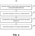
- FIG. 4 depicts an exemplary method for radiographic inspection according to the present disclosure.
- a radiographic inspection method 400 begins at 410 with a beam of x-rays being emitted by a line source.
- the line source can be mounted on a moveable platform and can emit a two-dimensional, fan-shaped beam of x-rays towards a structure to be inspected.
- the line source can be positioned on one side of a structure to be inspected, for example, underneath a wing of an aircraft as shown in FIGS. 1 and 2A or inside an aircraft fuselage as shown in FIG. 2B . While depicted in FIGS. 1 and 2A-2B as an aircraft, one of ordinary skill in the art will understand that the disclosed method is not limited to radiographic inspection of aircraft.
- the beam of x-rays is detected by a linear detector array.
- the linear detector array can be positioned on the opposite side of the structure to be inspected, for example, on the other side of the wing in FIGS. 1 and 2A or on the other side of the fuselage in FIG. 2B . In this manner, the beam ofx-rays can be detected by the linear detector array after the beam of x-rays passes through the structure being inspected.
- the line source and the linear detector array can be synchronously moved along or around an axis, essentially scanning the structure being inspected.
- the line source and the linear detector array can be synchronously moved along an axis representing a length of a wing of an airplane.
- the line source and the linear detector array can be synchronously moved around an axis extending down a length of a fuselage of an aircraft. Synchronous movement can be, for example, at a speed of one linear foot per minute or more.
- more than one scan may be needed to inspect an entirety of the structure being inspected which can be accomplished by moving one or both of the line source and the linear detector array.
- the image can be a real-time, two-dimensional image of a portion of the structure being inspected. From the image, the type and location of defects such as production defects or damage from use can be identified.
- use of a line source provides safety benefits by significantly reducing the amount of x-rays being emitted so evacuation of an area around the structure being inspected may no longer be required. This also allows other tasks such as maintenance or repairs to simultaneously be performed during inspection, saving down time. Furthermore, inspection time can be reduced from days to hours due to the synchronous movement of the line source and linear detector array.
- the linear x-ray detector can further be a multi-energy linear x-ray detector that includes multiple linear x-ray detectors stacked on top of each other and separated by one or more filters that each block x-rays below a certain energy threshold.
- This configuration allows each of the linear x-ray detectors in the multi-energy linear x-ray detector to detect x-rays having different energy ranges.
- FIG. 5 schematically depicts a side view of a portion of a multi-energy linear x-ray detector array 542 that includes a first linear x-ray detector 543, a second linear x-ray detector 544, and a third linear x-ray detector 545.
- First linear x-ray detector 543, second linear x-ray detector 544, and third linear x-ray detector 545 can be stacked atop each other and positioned to detect at least a portion of a fan shaped beam of x-rays 513 (represented by the dotted lines) generated by a line source 512.
- Each linear x-ray detector can be, for example, a one-dimensional x-ray detector having at least one row of x-ray sensitive detectors.
- the x-ray sensitive detectors can be, for example, a silicon (Si) or complementary metal-oxide-semiconductor (CMOS) based detector with scintillating materials on top. Scintillating materials can be, for example, CsI:Na, Gd 2 O 2 S, or CaWO 4 , to convert x-rays to visible light.
- CMOS complementary metal-oxide-semiconductor
- a first filter 554 resides between first linear x-ray detector 543 and second linear x-ray detector 544. First filter 554 blocks x-rays below a first energy threshold level from reaching second linear x-ray detector 544.
- a second filter 555 resides between second linear x-ray detector 544 and third linear x-ray detector 545. Second filter 555 blocks x-rays below a second energy threshold level from reaching third linear x-ray detector 545. The second energy threshold level is higher than the first energy threshold level, so that second x-ray detector 544 only detects x-rays having an energy above the second energy threshold level.
- Multi-energy linear x-ray detector array 542 can optionally include additional linear x-ray detectors and additional filters.
- FIG. 5 further depicts a fourth linear x-ray detector 546 positioned over third linear x-ray detector 545.
- a third filter 556 resides between third linear x-ray detector 545 and fourth linear x-ray detector 546.
- Third filter 556 blocks x-rays below a third energy threshold level from reaching fourth linear x-ray detector 546.
- the third energy threshold level is higher than the second energy threshold level, so that fourth x-ray detector 546 only detects x-rays having and energy above the third energy threshold level.
- Filters for example, first filter 554, second filter 555, and third filter 556, can be formed of any material that blocks x-rays.
- One of ordinary skill in the art understands that the lower the density of a material, the more transparent the material is to x-rays. Selection of materials for a filter will depend on the materials comprising the structure being inspected. However, the density of the material forming third filter 556 is higher than the density of the material forming second filter 555. And, the density of the material forming second filter 555 is higher than the density of the material forming first filter 554.
- materials for the first and second filter include, but are not limited to, hydrocarbon based materials, metal based materials, H2O based materials, Nitrate based materials, silicone based materials.
- line source 512 produces a fan shaped beam of x-rays 513 that pass through a structure being inspected.
- First linear x-ray detector 543 detects x-rays 513 having all energies, for example, from about 60 keV to about 220 keV.
- First filter 554 having a first energy level threshold of, for example, 80 keV passes only x-rays having energies above 80 keV to be detected by second linear x-ray detector 544.
- Second filter 555 having a second energy level threshold of, for example, 125 keV passes only x-rays having energies above 125 keV to be detected by third linear x-ray detector 545.
- first filter 554 and second filter 555 By selection of materials for first filter 554 and second filter 555, inspection of structures and components formed of multiple types of materials including metals, composites, and plastics can be accomplished to detect FOD based on atomic density, as well as defects or damage of the structure or component being inspected. Results of the inspection can be shown on a display, such as, display 370 depicted in FIG 3 .
- Display 370 can show all or a portion of the structure being inspected, for example, as a multi-color image where each color represents a range of atomic numbers. By overlaying images produced from data collected by each x-ray detector, the multi-color overlaid image can show defects in different materials having different atomic numbers.
Landscapes
- Physics & Mathematics (AREA)
- Health & Medical Sciences (AREA)
- General Physics & Mathematics (AREA)
- Life Sciences & Earth Sciences (AREA)
- Biochemistry (AREA)
- Analytical Chemistry (AREA)
- Chemical & Material Sciences (AREA)
- General Health & Medical Sciences (AREA)
- Immunology (AREA)
- Pathology (AREA)
- Toxicology (AREA)
- High Energy & Nuclear Physics (AREA)
- General Life Sciences & Earth Sciences (AREA)
- Geophysics (AREA)
- Analysing Materials By The Use Of Radiation (AREA)
Abstract
A system for radiographic inspection includes a line source that emits a fan shaped beam of x-rays and a linear x-ray detector that detects the fan shaped beam of x-rays. The system further includes a first movable platform that positions the line source to emit the fan shaped beam of x-rays towards the linear x-ray detector. A second movable platform positions the linear x-ray detector to detect the fan shaped beam of x-rays after transmission through the structure or component being inspected. Synchronized movement of the first movable platform and the second movable platform significantly reduces the time of inspection while the fan shaped beam of x-rays minimizes health risks. The system further includes a first filter that blocks x-rays below a first energy threshold, and a second filter that blocks x-rays below a second energy threshold. The filters provide the system the ability to inspect structures and components formed of multiple types of materials, for example, foreign object debris.
Description
- The present disclosure relates to systems and methods for nondestructive inspection (NDI) of structures and components. More particularly, the present disclosure relates to systems and methods for radiographic inspection of structures and components that detect foreign object debris.
- Radiography is a commonly used nondestructive inspection (NDI) technique to detect defects in structures and components. Current digital radiography inspection systems, however, are costly and time consuming. For example, digital radiography is routinely used to inspect aircraft for defects such as cracks or corrosion. Current digital radiography inspection systems use a large x-ray source and digital detector arrays that require constant alignment of the beam of x-rays. For a large structure such as an aircraft, inspection of the wings and fuselage can last for two or more days and generate large amounts of data that must be assessed. And, due to the large amount of x-rays generated and the health hazard that could be posed by exposure thereto, the entire area near the aircraft must be cleared of people during the two or more days required for inspection thereby precluding any contemporaneous activity such as repair or other types of inspection. Current digital radiography inspection systems used to inspect aircraft also cannot accurately detect foreign object debris (FOD) due to their inability to discriminate between the atomic number of materials. FOD includes objects left on or within an aircraft after completion of assembly. Examples include, but are not limited to, tools, metal shavings, plastic pieces, drill bits, gloves, and rags. For aircraft in use, FOD on a runway, for example, can be run over and strike the aircraft and cause damage. For example, tools, screws, or other objects, left on the runway can be run over by the aircraft or other vehicles and strike the wing or fuselage causing damage. As a result, improved x-ray systems and methods for nondestructive inspection are desired.
- According to the present disclosure, a system for transmission radiographic inspection of a structure is provided. The system for transmission radiographic inspection includes a first movable platform and a line source coupled to the first movable platform, wherein the line source emits a fan shaped beam of x-rays. The system for transmission radiographic inspection further includes a second movable platform, a first linear x-ray detector coupled to the second movable platform, wherein the first linear x-ray detector is positioned to detect the fan shaped beam of x-rays, and at least one position sensor and an encoder to synchronize movement of the first movable platform and second movable platform.
- According to a form of embodiment of the present disclosure, the system includes a second linear x-ray detector positioned over the first linear x-ray detector, and a first filter positioned between the first linear x-ray detector and the second linear x-ray detector, wherein the first filter is configured to block x-rays below a first energy threshold level. The system also includes a third linear x-ray detector positioned over the second linear x-ray detector and a second filter positioned between the second linear x-ray detector and the third linear x-ray detector, wherein the second filter is configured to block x-rays below a second energy threshold level. The system further includes a first movable mount that positions the line source to emit the beam of x-rays towards the first, second, and third linear x-ray detectors, a second movable mount that positions the first, second, and third linear x-ray detectors to detect the beam of x-rays, whereby the at least one position sensor and the encoder are configured to synchronize movement of the line source and first, second, and third linear x-ray detectors along and/or around an axis.
- According to the present disclosure a method for inspecting a structure is provided. The method includes emitting a beam of x-rays from a line source towards a structure being inspected, wherein the beam of x-rays comprise a fan shape, detecting the beam of x-rays by at least one linear x-ray detector subsequent to the beam of x-rays passing through the structure being inspected, and moving, synchronously, the line source and the linear x-ray detector along the structure being inspected during the emitting the x-ray beam and detecting the x-rays, and displaying a real-time, two-dimensional image of a portion of the structure being inspected.
- According to a way of carrying out the method according to the present disclosure, the detecting is carried out by a multi-energy linear x-ray detector that includes multiple linear x-ray detectors stacked on top of each other and separated by one or more filters that block x-rays below a certain energy threshold subsequent to the beam of x-rays passing through the structure being inspected.
- The accompanying drawings, which are incorporated in and constitute a part of this specification, illustrate aspects of the present teachings and together with the description, serve to explain the principles of the present teachings.
-
FIG. 1 schematically illustrates a system for radiographic inspection of a structure, according to an implementation. -
FIG. 2A schematically illustrates a system for radiographic inspection with synchronous movement of the x-ray line source and linear detector array along an axis, according to an implementation. -
FIG. 2B schematically illustrates a system for radiographic inspection with synchronous movement of the x-ray line source and linear detector array around an axis, according to an implementation. -
FIG. 3 schematically illustrates a system for radiographic inspection of a structure, according to an implementation. -
FIG. 4 schematically illustrates a method for radiographic inspection of a structure, according to an implementation. -
FIG. 5 schematically illustrates a multi-energy linear x-ray detector, according to an implementation. - Reference will now be made in detail to the present teachings, examples of which are illustrated in the accompanying drawings. In the drawings, like reference numerals have been used throughout to designate identical elements. In the following description, reference is made to the accompanying drawings that form a part thereof, and in which is shown, by way of non-limiting illustration, specific examples of practicing the present teachings. The following description is, therefore, merely exemplary.
- The present disclosure is directed to systems and methods for radiographic inspection of structures and components. The system includes a line source that emits a fan shaped beam of x-rays and a linear x-ray detector that detects the fan shaped beam of x-rays. As used herein, a fan shaped beam of x-rays refers to essentially a two-dimensional beam of x-rays that diverge as the beam radiates away from a line source of x-rays. Because the line source and linear x-ray detector isolate the x-rays to a two-dimensional fan shape, a reduced amount of x-rays can be used for inspection compared to conventional systems. As a result, the need to evacuate the inspection area to minimize health risks is avoided. The system further includes a first movable platform that positions the line source to emit the fan shaped beam of x-rays towards the linear x-ray detector. A second movable platform position the linear x-ray detector to detect the fan shaped beam of x-rays after transmission through the structure or component being inspected. By synchronizing movement of the first movable platform and second movable platform to scan the structure or component with the fan shaped beam of x-rays, inspection can be completed in a fraction of the time compared to conventional radiographic systems and methods. The system can further include a first filter that blocks x-rays below a first energy threshold, and a second filter that blocks x-rays below a second energy threshold. The filters provide the system the ability to inspect structures and components formed of multiple types of materials with different atomic numbers including metals, composites, and plastics, to detect FOD on or within the structure being inspected, as well as to detect defects or damage.
-
FIG. 1 shows aradiographic inspection system 100 according to the present disclosure.Radiographic inspection system 100 includes anx-ray generation portion 110 and anx-ray detection portion 120.FIG. 1 further depicts awing 180 of anaircraft 190 as an exemplary structure to be inspected. Although depicted as an aircraft, one of ordinary skill in the art will understand that use of radiography inspection system is not limited to aircraft and aircraft components.X-ray generation portion 110 ofradiographic inspection system 100 provides a beam of x-rays directed towardswing 180. In various aspects, the beam of x-rays can be linear in shape and have a two-dimensional fan or triangular shape.X-ray detection portion 120 ofradiographic inspection system 100 detects the beam of x-rays after transmission throughwing 180. Nondestructive inspection ofwing 180 can be accomplished by synchronously moving, also referred to herein as scanning,x-ray generation portion 110 andx-ray detection portion 120 along a length and/or width ofwing 180 as x-rays generated byx-ray generation portion 110 are detected byx-ray detection portion 120 after transmission of the linear fan shaped x-rays throughwing 180. -
FIG. 2A provides further details of x-ray generation portion and x-ray detection portion of aradiographic inspection system 200 according to the present disclosure. Anx-ray generation portion 210 includes aline source 212 and a firstmovable platform 216. -
Line source 212 includes an x-ray tube and a linear aperture positioned to provide a linear, diverging beam of x-rays. Use ofline source 212 minimizes the amount of x-rays that stray from the inspection area and reduces the health hazard to personnel in the vicinity ofsystem 200. The x-ray tube can be glass or ceramic and have power ranging from about 100 to about 4000 watts and voltages ranging from about 30 to about 450 kV. Suitable x-ray tubes are manufactured by, for example, Phillips (Amsterdam, Netherlands), Varian (Palo Alto, CA), and General Electric (Boston, MA).Line source 212 can further include a cooling system, for example, circulating water or closed cycle cooling to control the temperature of the x-ray tube. The linear aperture can be positioned adjacent to the x-ray tube and serve to block x-rays. X-rays not blocked by the linear aperture form the linear, diverging (e.g., fan shaped) beam of x-rays that can be used for inspection. The linear aperture can be formed of any material that blocks x-rays, including but not limited to lead, steel, and tungsten. -
Line source 212 is coupled to firstmovable platform 216. Firstmovable platform 216positions line source 212 to emit the fan shaped beam of x-rays towards a structure to be inspected, depicted inFIG. 2A as awing 280 of an aircraft. Firstmovable platform 216 further allows movement ofx-ray generation portion 210. AlthoughFIG. 2A depicts firstmovable platform 216 with wheels that roll along the ground underwing 280, other movable platforms are envisioned including, but not limited to, a robotic arm, a conveyor belt, a track, a drone, an all wheel crawler, holonic wheels and suction cup wheels. -
X-ray detection portion 220 includes anx-ray detector 222 and a secondmovable platform 226.X-ray detector 222 can be, for example, a linear x-ray detector array having a one-dimensional x-ray detector with at least one row of x-ray sensitive detectors. The x-ray sensitive detectors can be, for example, a silicon (Si) or complementary metal-oxide-semiconductor (CMOS) based detector with scintillating materials on top. Scintillating materials can be, for example, CsI:Na, Gd2O2S, or CaWO4, to convert x-rays to visible light. -
X-ray detector 222 is coupled to secondmovable platform 226. Secondmovable platform 226positions x-ray detector 222 to detect the fan shaped beam of x-rays after transmission through a structure to be inspected, depicted inFIG. 2A as awing 280 of an aircraft. Secondmovable platform 226 further allows synchronous movement ofx-ray detector 222 andline source 212. AlthoughFIG. 2A depicts secondmovable platform 226 as a robotic arm positioned overwing 280, other movable platforms are envisioned that include, but are not limited to, a wheeled platform as depicted inFIG. 1 , a conveyor belt, a track, a drone, an all wheel crawler, holonic wheels and suction cup wheelsFIG. 2A depictsradiographic inspection system 200 having synchronized movement ofx-ray generation portion 210 withx-ray detection portion 220 along an axis, for example, a length or long dimension ofwing 280. In further aspects, synchronized movement ofx-ray generation portion 210 withx-ray detection portion 220 can be around an axis.FIG. 2B illustrates a cross section of, for example, afuselage 290 of an aircraft.X-ray generation portion 210 is disposed withinfuselage 290, for example at an axis offuselage 290, whilex-ray detection portion 220 is disposed outside offuselage 290. Firstmovable platform 216positions line source 212 to emit the fan shaped beam of x-rays towardsfuselage 290. Firstmovable platform 216 allows rotation of ofx-ray generation portion 210 so that the fan shaped beam of x-rays can inspectfuselage 290. Rotation of x-ray beam is illustrated inFIG. 2B by afirst position 213 of the x-ray beam and asecond position 214 of the x-ray beam and dottedcurved line 215. Secondmovable platform 226positions x-ray detector 222 to detect the fan shaped beam of x-rays after transmission throughfuselage 290 and around an outside offuselage 290 as illustrated by dottedcurved line 291. Depending on a width of the fan shaped beam of x-rays,x-ray generation portion 210 andx-ray detection portion 220 may also be moved along the axis to inspect other portions of thefuselage 290. - Referring to
FIG. 3 , aradiographic inspection system 300 further includesposition sensors encoder 340 to synchronize movement of the first movable platform and second movable platform. According to the present disclosure, the first movable platform and second movable platform can move at a speed of at least one linear foot per minute. This allows inspection to be completed in less time than conventional transmission radiographic systems. As disclosed herein,line source 312 provides a beam of x-rays having a linear shape resembling a fan andlinear x-ray detector 322 includes a one-dimensional x-ray detector having at least one row of x-ray sensitive detectors. As a result, synchronizing movement of firstmovable platform 316 and secondmovable platform 326 allowslinear x-ray detector 322 to detect the linear shaped x-ray beam after transmission through wing 280 (shown inFIG. 2A ).Position sensors -
Radiographic inspection system 300 further includes acomputer 350 andcontroller 360. Computer is operably coupled to positionsensors encoder 340, firstmovable platform 316 and secondmovable platform 326.Computer 350 includes processors and a memory system including one or more non-transitory computer readable media storing instructions that, when executed, synchronizes movement of firstmovable platform 316 and secondmovable platform 326 along a structure being inspected, for example,wing 280. In particular,computer 350, throughposition sensors encoder 340, via processors and software, synchronizes movement of firstmovable platform 316 and secondmovable platform 326 alongwing 280 so thatlinear x-ray detector 322 detects the linear shaped x-ray beam after transmission throughwing 280.Computer 350 further provides instructions toline source 312 to generate the fan shaped beam of x-rays and receives data fromlinear x-ray detector 322.Radiographic inspection system 200 can further include a display 370 to show an image of all or a portion ofwing 280 and any defects detected by the x-rays. The image shown on display 370 can be real-time image of a structure being inspected and can show the presence and location of FOD on or within the structure being inspected, as well as defects in the structure being inspected. Defects include, but are not limited to, damage resulting from foreign object debris striking the structure being inspected, a crack, delamination, and voids. -
FIG. 4 depicts an exemplary method for radiographic inspection according to the present disclosure. Aradiographic inspection method 400 begins at 410 with a beam of x-rays being emitted by a line source. As disclosed herein, the line source can be mounted on a moveable platform and can emit a two-dimensional, fan-shaped beam of x-rays towards a structure to be inspected. The line source can be positioned on one side of a structure to be inspected, for example, underneath a wing of an aircraft as shown inFIGS. 1 and 2A or inside an aircraft fuselage as shown inFIG. 2B . While depicted inFIGS. 1 and2A-2B as an aircraft, one of ordinary skill in the art will understand that the disclosed method is not limited to radiographic inspection of aircraft. - At 420 of
radiographic inspection method 400, the beam of x-rays is detected by a linear detector array. The linear detector array can be positioned on the opposite side of the structure to be inspected, for example, on the other side of the wing inFIGS. 1 and 2A or on the other side of the fuselage inFIG. 2B . In this manner, the beam ofx-rays can be detected by the linear detector array after the beam of x-rays passes through the structure being inspected. - At 430 of
radiographic inspection method 400, the line source and the linear detector array can be synchronously moved along or around an axis, essentially scanning the structure being inspected. For example, the line source and the linear detector array can be synchronously moved along an axis representing a length of a wing of an airplane. In another example, the line source and the linear detector array can be synchronously moved around an axis extending down a length of a fuselage of an aircraft. Synchronous movement can be, for example, at a speed of one linear foot per minute or more. One of ordinary skill in the art will understand that more than one scan may be needed to inspect an entirety of the structure being inspected which can be accomplished by moving one or both of the line source and the linear detector array. - At 440 of
radiographic inspection method 400, displaying an image of a portion of the structure being inspected occurs. The image can be a real-time, two-dimensional image of a portion of the structure being inspected. From the image, the type and location of defects such as production defects or damage from use can be identified. As discussed herein, use of a line source provides safety benefits by significantly reducing the amount of x-rays being emitted so evacuation of an area around the structure being inspected may no longer be required. This also allows other tasks such as maintenance or repairs to simultaneously be performed during inspection, saving down time. Furthermore, inspection time can be reduced from days to hours due to the synchronous movement of the line source and linear detector array. - According to the present disclosure, the linear x-ray detector can further be a multi-energy linear x-ray detector that includes multiple linear x-ray detectors stacked on top of each other and separated by one or more filters that each block x-rays below a certain energy threshold. This configuration allows each of the linear x-ray detectors in the multi-energy linear x-ray detector to detect x-rays having different energy ranges.
FIG. 5 schematically depicts a side view of a portion of a multi-energy linearx-ray detector array 542 that includes a firstlinear x-ray detector 543, a secondlinear x-ray detector 544, and a thirdlinear x-ray detector 545. Firstlinear x-ray detector 543, secondlinear x-ray detector 544, and thirdlinear x-ray detector 545 can be stacked atop each other and positioned to detect at least a portion of a fan shaped beam of x-rays 513 (represented by the dotted lines) generated by aline source 512. Each linear x-ray detector can be, for example, a one-dimensional x-ray detector having at least one row of x-ray sensitive detectors. The x-ray sensitive detectors can be, for example, a silicon (Si) or complementary metal-oxide-semiconductor (CMOS) based detector with scintillating materials on top. Scintillating materials can be, for example, CsI:Na, Gd2O2S, or CaWO4, to convert x-rays to visible light. - A
first filter 554 resides between firstlinear x-ray detector 543 and secondlinear x-ray detector 544.First filter 554 blocks x-rays below a first energy threshold level from reaching secondlinear x-ray detector 544. Asecond filter 555 resides between secondlinear x-ray detector 544 and thirdlinear x-ray detector 545.Second filter 555 blocks x-rays below a second energy threshold level from reaching thirdlinear x-ray detector 545. The second energy threshold level is higher than the first energy threshold level, so thatsecond x-ray detector 544 only detects x-rays having an energy above the second energy threshold level. - Multi-energy linear
x-ray detector array 542 can optionally include additional linear x-ray detectors and additional filters. For example,FIG. 5 further depicts a fourthlinear x-ray detector 546 positioned over thirdlinear x-ray detector 545. Athird filter 556 resides between thirdlinear x-ray detector 545 and fourthlinear x-ray detector 546.Third filter 556 blocks x-rays below a third energy threshold level from reaching fourthlinear x-ray detector 546. The third energy threshold level is higher than the second energy threshold level, so thatfourth x-ray detector 546 only detects x-rays having and energy above the third energy threshold level. - Filters, for example,
first filter 554,second filter 555, andthird filter 556, can be formed of any material that blocks x-rays. One of ordinary skill in the art understands that the lower the density of a material, the more transparent the material is to x-rays. Selection of materials for a filter will depend on the materials comprising the structure being inspected. However, the density of the material formingthird filter 556 is higher than the density of the material formingsecond filter 555. And, the density of the material formingsecond filter 555 is higher than the density of the material formingfirst filter 554. Examples of materials for the first and second filter include, but are not limited to, hydrocarbon based materials, metal based materials, H2O based materials, Nitrate based materials, silicone based materials. - In operation,
line source 512 produces a fan shaped beam ofx-rays 513 that pass through a structure being inspected. Firstlinear x-ray detector 543 detectsx-rays 513 having all energies, for example, from about 60 keV to about 220 keV.First filter 554 having a first energy level threshold of, for example, 80 keV passes only x-rays having energies above 80 keV to be detected by secondlinear x-ray detector 544.Second filter 555 having a second energy level threshold of, for example, 125 keV passes only x-rays having energies above 125 keV to be detected by thirdlinear x-ray detector 545. By selection of materials forfirst filter 554 andsecond filter 555, inspection of structures and components formed of multiple types of materials including metals, composites, and plastics can be accomplished to detect FOD based on atomic density, as well as defects or damage of the structure or component being inspected. Results of the inspection can be shown on a display, such as, display 370 depicted inFIG 3 . Display 370 can show all or a portion of the structure being inspected, for example, as a multi-color image where each color represents a range of atomic numbers. By overlaying images produced from data collected by each x-ray detector, the multi-color overlaid image can show defects in different materials having different atomic numbers. - Notwithstanding that the numerical ranges and parameters setting forth the broad scope of the disclosure are approximations, the numerical values set forth in the specific examples are reported as precisely as possible. Any numerical value, however, inherently contains certain errors necessarily resulting from the standard deviation found in their respective testing measurements. Moreover, all ranges disclosed herein are to be understood to encompass any and all sub-ranges subsumed therein.
- While the present teachings have been illustrated with respect to one or more implementations, alterations and/or modifications can be made to the illustrated examples without departing from the contents of the appended claims. As used herein, the terms "a", "an", and "the" may refer to one or more elements or parts of elements. As used herein, the terms "first" and "second" may refer to two different elements or parts of elements. As used herein, the term "at least one of A and B" with respect to a listing of items such as, for example, A and B, means A alone, B alone, or A and B. Those skilled in the art will recognize that these and other variations are possible. Furthermore, to the extent that the terms "including," "includes," "having," "has," "with," or variants thereof are used in either the detailed description and the claims, such terms are intended to be inclusive in a manner similar to the term "comprising." Further, in the discussion and claims herein, the term "about" indicates that the value listed may be somewhat altered, as long as the alteration does not result in nonconformance of the process or structure to the intended purpose described herein. Finally, "exemplary" indicates the description is used as an example, rather than implying that it is an ideal.
- It will be appreciated that variants of the above-disclosed and other features and functions, or alternatives thereof, may be combined into many other different systems or applications. Further, the disclosure includes embodiments according to the following clauses.
-
Clause 1. A system for radiographic inspection comprising:- a first movable platform;
- a line source coupled to the first movable platform, wherein the line source emits a fan shaped beam of x-rays;
- a second movable platform;
- a linear x-ray detector coupled to the second movable platform, wherein the linear x-ray detector is positioned to detect the fan shaped beam of x-rays; and
- a position sensor and an encoder to synchronize movement of the first movable platform and second movable platform.
- Clause 2. The system of
clause 1, wherein the position sensor and the encoder synchronizes movement of the first movable platform and second movable platform along an axis. - Clause 3. The system of
clause 1, wherein the position sensor and the encoder synchronizes movement of the first movable platform and second movable platform around an axis. - Clause 4. The system of
clause 1, wherein the first movable platform comprises a robotic arm, a conveyor belt, or a track to synchronously move the line source and the linear x-ray detector. - Clause 5. The system of
clause 1, wherein the second movable platform comprises a robotic arm, a conveyor belt, or a track to synchronously move the line source with the linear x-ray detector over a surface of a structure under inspection. - Clause 6. The system of
clause 1, wherein the first movable platform and second movable platform move at a speed of at least one linear foot per minute. - Clause 7. The system of
clause 1, further comprising a display to show a real-time two-dimensional image of a structure being inspected, wherein the real-time, two-dimensional images are based on detection, by the linear x-ray detector, of x-rays transmitted through structure being inspected. - Clause 8. The system of clause 7, wherein the real-time, two-dimensional images show a presence and a location of a defect in the structure being inspected.
- Clause 9. The system of clause 7, wherein the real-time, two-dimensional images show foreign object debris on or within the structure being inspected.
- Clause 10. A system for radiographic inspection comprising:
- a line source that emits a beam of x-rays;
- a first linear x-ray detector;
- a second linear x-ray detector positioned over the first linear x-ray detector;
- a first filter positioned between the first linear x-ray detector and the second linear x-ray detector, wherein the first filter blocks x-rays below a first energy threshold level;
- a third linear x-ray detector positioned over the second linear x-ray detector;
- a second filter positioned between the second linear x-ray detector and the third linear x-ray detector, wherein the second filter blocks x-rays below a second energy threshold level;
- a first movable mount that positions the line source to emit the beam of x-rays towards the first, second, and third linear x-ray detectors;
- a second movable mount that positions the first, second, and third linear x-ray detectors to detect the beam of x-rays; and
- a position sensor and an encoder to synchronize movement of the line source and first, second, and third linear x-ray detectors along or around an axis.
- Clause 11. The system of clause 10, wherein the second energy threshold level is higher than the first energy threshold level.
- Clause 12. The system of clause 10, further comprising:
- a fourth linear x-ray detector positioned over the third linear x-ray detector; and
- a third filter positioned between the third linear x-ray detector and the fourth linear x-ray detector, wherein the third filter blocks x-rays below a third energy threshold level.
- Clause 13. The system of clause 12, wherein the third energy threshold level is higher than the second energy threshold level.
- Clause 14. The system of clause 10, wherein the first filter blocks x-rays below 60 keV.
- Clause 15. The system of clause 10, wherein the second filter blocks x-rays below 80 keV.
- Clause 16. The system of clause 10, further including a third filter that blocks x-rays below 125 keV.
- Clause 17. The system of clause 10, further comprising a display to show an image of a structure being inspected, wherein the image is based on detection, by the linear x-ray detector, of x-rays transmitted through the structure being inspected.
- Clause 18. The system of clause 17, wherein the image is a real-time, two-dimensional image of the structure being inspected.
- Clause 19. The system of clause 18, wherein the real-time, two-dimensional image shows a presence and a location of a defect in the structure being inspected.
- Clause 20. The system of clause 19, wherein the real-time, two-dimensional images show a defect in one or more of a metal material, a composite material, and a plastic material within the structure being inspected.
- Clause 21. A method for inspecting a structure comprising: emitting a beam of x-rays from a line source towards a structure being inspected, wherein the beam of x-rays comprise a fan shape; detecting the beam of x-rays by a linear x-ray detector subsequent to the beam of x-rays passing through the structure being inspected; moving, synchronously, the line source and the linear x-ray detector along the structure being inspected during the emitting the x-ray beam and detecting the x-rays; and displaying a real-time, two-dimensional image of a portion of the structure being inspected.
- Clause 22. The method of clause 21, wherein moving, synchronously, the line source and the linear x-ray detector along the structure comprises a speed of one linear foot per minute or more.
- Clause 23. The method of clause 21, wherein displaying a real-time, two-dimensional image of a portion of the structure being inspected comprises displaying a defect in a composite portion of the structure being inspected.
- Clause 24. The method of clause 21, wherein displaying a real-time, two-dimensional image of a portion of the structure being inspected comprises displaying a defect in a plastic portion of the structure being inspected.
- Clause 25. A method for inspecting a structure comprising: emitting a beam of x-rays from a line source towards a structure being inspected, wherein the beam of x-rays comprise a fan shape; detecting the beam of x-rays by a multi-energy linear x-ray detector that includes multiple linear x-ray detectors stacked on top of each other and separated by one or more filters that block x-rays below a certain energy threshold subsequent to the beam of x-rays passing through the structure being inspected; moving, synchronously, the line source and the linear x-ray detector along the structure being inspected during the emitting the x-ray beam and detecting the x-rays.
- Clause 26. The method of clause 25 further comprising displaying a real-time, two-dimensional image of at least a portion of the structure being inspected based on the detected x-rays.
- Clause 27. The method of clause 25 further comprising identifying a type and location of a defect in the structure being inspected.
- Clause 28. The method of clause 25, further comprises blocking x-rays below a first energy threshold using a first filter and blocking x-rays below a second energy threshold using a second filter, wherein the first energy threshold is lower than the second energy threshold.
- Clause 29. The method of clause 26, wherein the first energy threshold is 60 keV and the second energy threshold is 80 keV.
- Clause 30. The method of clause 25, further comprises blocking x-rays below a third energy threshold, wherein the third energy threshold is 125 keV.
- Clause 31. The method of clause 25, wherein displaying a real-time, two-dimensional image of a portion of the structure being inspected comprises displaying a defect in a metal portion of the structure being inspected.
Claims (15)
- A system (100,200) for radiographic inspection of a structure (280, 290) comprising:a first movable platform (216, 316);a line source (212, 312, 512) coupled to the first movable platform (216, 316), wherein the line source (212, 312, 512) emits a fan shaped beam of x-rays;a second movable platform (226, 326);a first linear x-ray detector coupled to the second movable platform (226, 326), wherein the first linear x-ray detector is positioned to detect the fan shaped beam of x-rays; andat least one position sensor and an encoder (340) to synchronize movement of the first movable platform (216, 316) and second movable platform (226, 326).
- The system (100, 200) of claim 1, wherein the at least one position sensor and the encoder (340) are configured to synchronize movement of the first movable platform (216, 316) and second movable platform (226, 326) along and/or around an axis.
- The system (100, 200) of any one of the preceding claims, wherein each one of the first movable platform (216, 316) and the second movable platform (226, 326) either comprises a robotic arm, or a conveyor belt, or a track, or a drone, or an all wheel crawler, or holonic wheels or suction cup wheels which is/are configured to synchronously move the line source (212, 312, 512) and the linear x-ray detector.
- The system (100, 200) of any one of the preceding claims, wherein the first movable platform (216, 316) and second movable platform (226, 326) are configured to move at a speed of at least 30 linear centimeters (one linear foot) per minute.
- The system (100, 200) of any one of the preceding claims, further comprising a display (370) which is configured to show a real-time two-dimensional image of the structure (280, 290) being inspected, wherein the real-time, two-dimensional images are based on detection, by the first linear x-ray detector, of x-rays transmitted through the structure (280, 290) being inspected.
- The system (100, 200) of any one of the preceding claims, further comprising:- a second linear x-ray detector positioned over the first linear x-ray detector;- a first filter (554) positioned between the first linear x-ray detector and the second linear x-ray detector, wherein the first filter (554) is configured to block x-rays below a first energy threshold level;- a third linear x-ray detector positioned over the second linear x-ray detector;- a second filter (555) positioned between the second linear x-ray detector and the third linear x-ray detector, wherein the second filter (555) is configured to block x-rays below a second energy threshold level;- a first movable mount that positions the line source (212, 312, 512) to emit the beam of x-rays towards the first, second, and third linear x-ray detectors;- a second movable mount that positions the first, second, and third linear x-ray detectors to detect the beam of x-rays;- whereby the at least one position sensor and the encoder (340) are configured to synchronize movement of the line source (212, 312, 512) and first, second, and third linear x-ray detectors along and/or around an axis.
- The system (100, 200) of claim 6, wherein the second energy threshold level is higher than the first energy threshold level.
- The system (100, 200) of any one of claims 6-7, further comprising:- a fourth linear x-ray detector positioned over the third linear x-ray detector; and- a third filter (556) positioned between the third linear x-ray detector and the fourth linear x-ray detector, wherein the third filter (556) is configured to block x-rays below a third energy threshold level.
- The system (100, 200) of claim 8, wherein the third energy threshold level is higher than the second energy threshold level.
- The system (100, 200) of any one of claims 6-9, wherein the first filter (554) is configured to block x-rays below 60 keV.
- The system (100, 200) of any one of claims 6-10, wherein the second filter (555) is configured to block x-rays below 80 keV.
- The system (100, 200) of any one of claims 6-11, further including a third filter (556) that is configured to block x-rays below 125 keV.
- A method (400) for inspecting a structure comprising:- emitting (410) a beam of x-rays from a line source towards a structure being inspected, wherein the beam of x-rays comprise a fan shape;- detecting (420) the beam of x-rays by at least one linear x-ray detector subsequent to the beam of x-rays passing through the structure being inspected;- moving (430), synchronously, the line source and the linear x-ray detector along the structure being inspected during the emitting the x-ray beam and detecting the x-rays; and- displaying (440) a real-time, two-dimensional image of a portion of the structure being inspected.
- The method of claim 13, wherein the detecting (420) is carried out by a multi-energy x-ray detector that includes multiple linear x-ray detectors staked on top of each other and separated by one or more filters that block x-rays below a certain energy threshold subsequent to the beam of x-rays passing through the structure being inspected.
- The method of claim 14, wherein blocking x-rays below a first energy threshold is carried out using a first filter and blocking e-rays below a second energy threshold is carried out using a second filter, wherein the first energy threshold is lower than the second energy threshold.
Applications Claiming Priority (1)
| Application Number | Priority Date | Filing Date | Title |
|---|---|---|---|
| US18/182,975 US20240310306A1 (en) | 2023-03-13 | 2023-03-13 | X-ray line scan for foreign object debris detection |
Publications (1)
| Publication Number | Publication Date |
|---|---|
| EP4431926A1 true EP4431926A1 (en) | 2024-09-18 |
Family
ID=90105250
Family Applications (1)
| Application Number | Title | Priority Date | Filing Date |
|---|---|---|---|
| EP24159612.1A Pending EP4431926A1 (en) | 2023-03-13 | 2024-02-26 | X-ray line scan for foreign object debris detection |
Country Status (2)
| Country | Link |
|---|---|
| US (1) | US20240310306A1 (en) |
| EP (1) | EP4431926A1 (en) |
Citations (6)
| Publication number | Priority date | Publication date | Assignee | Title |
|---|---|---|---|---|
| US20030043964A1 (en) * | 2001-08-31 | 2003-03-06 | Jetray Corporation | Inspection system and method |
| US20060198498A1 (en) * | 2005-03-07 | 2006-09-07 | General Electric Company | Radiographic inspection of airframes and other large objects |
| GB2519692A (en) * | 2012-07-26 | 2015-04-29 | Univ Tsinghua | Combined ray non-destructive testing method and system |
| EP3614131A1 (en) * | 2009-10-29 | 2020-02-26 | Rapiscan Systems, Inc. | Mobile aircraft inspection system |
| CN112098441A (en) * | 2020-08-26 | 2020-12-18 | 上海奕瑞光电子科技股份有限公司 | Three-level linear array detector for single-source multi-energy imaging system |
| US20230049542A1 (en) * | 2021-08-13 | 2023-02-16 | Mistras Group, Inc. | Automated circumferential pipe scanning system |
Family Cites Families (68)
| Publication number | Priority date | Publication date | Assignee | Title |
|---|---|---|---|---|
| US5033073A (en) * | 1987-11-24 | 1991-07-16 | Boeing Company | System for radiograhically inspecting a relatively stationary object and related method |
| US5864146A (en) * | 1996-11-13 | 1999-01-26 | University Of Massachusetts Medical Center | System for quantitative radiographic imaging |
| US5237598A (en) * | 1992-04-24 | 1993-08-17 | Albert Richard D | Multiple image scanning X-ray method and apparatus |
| US5740224A (en) * | 1994-09-27 | 1998-04-14 | University Of Delaware | Cone beam synthetic arrays in three-dimensional computerized tomography |
| FI97646C (en) * | 1994-10-19 | 1997-01-27 | Kvaerner Masa Yards Oy | Apparatus for testing welded sheet metal assemblies |
| US5583904A (en) * | 1995-04-11 | 1996-12-10 | Hewlett-Packard Co. | Continuous linear scan laminography system and method |
| US5638420A (en) * | 1996-07-03 | 1997-06-10 | Advanced Research And Applications Corporation | Straddle inspection system |
| US5984023A (en) * | 1996-07-26 | 1999-11-16 | Advanced Coring Technology | Downhole in-situ measurement of physical and or chemical properties including fluid saturations of cores while coring |
| US6380540B1 (en) * | 1997-01-29 | 2002-04-30 | Ge Medical Systems Israel, Ltd. | Radiation imaging using simultaneous emission and transmission |
| US6111929A (en) * | 1997-03-14 | 2000-08-29 | Xrf Corporation | Scanning X-ray fluorescence analyzer |
| US7010094B2 (en) * | 2000-02-10 | 2006-03-07 | American Science And Engineering, Inc. | X-ray inspection using spatially and spectrally tailored beams |
| US6373917B1 (en) * | 2000-08-30 | 2002-04-16 | Agilent Technologies, Inc. | Z-axis elimination in an X-ray laminography system using image magnification for Z plane adjustment |
| US6614872B2 (en) * | 2001-01-26 | 2003-09-02 | General Electric Company | Method and apparatus for localized digital radiographic inspection |
| US6507635B2 (en) * | 2001-03-30 | 2003-01-14 | General Electric Company | Method and apparatus for radiographic inspection of aircraft fuselages |
| US6618465B2 (en) * | 2001-11-12 | 2003-09-09 | General Electric Company | X-ray shielding system and shielded digital radiographic inspection system and method |
| US6662088B1 (en) * | 2002-06-28 | 2003-12-09 | General Electric Company | Methods and systems for inspecting aircraft fuselage frames |
| US7356115B2 (en) * | 2002-12-04 | 2008-04-08 | Varian Medical Systems Technology, Inc. | Radiation scanning units including a movable platform |
| US7103137B2 (en) * | 2002-07-24 | 2006-09-05 | Varian Medical Systems Technology, Inc. | Radiation scanning of objects for contraband |
| SE527139C2 (en) * | 2003-04-16 | 2005-12-27 | Xcounter Ab | Device and method for dual-energy and scan-based detection of ionized radiation with stacked line detectors and filters |
| US6937692B2 (en) * | 2003-06-06 | 2005-08-30 | Varian Medical Systems Technologies, Inc. | Vehicle mounted inspection systems and methods |
| JP5408873B2 (en) * | 2004-05-26 | 2014-02-05 | ベルス・メステヒニーク・ゲーエムベーハー | Calibration method of X-ray sensing device in coordinate measuring device |
| US7050535B2 (en) * | 2004-09-16 | 2006-05-23 | The Boeing Company | X-ray laminography inspection system and method |
| US7315609B2 (en) * | 2004-09-16 | 2008-01-01 | The Boeing Company | Real-time X-ray scanner and remote crawler apparatus and method |
| FR2879767B1 (en) * | 2004-12-17 | 2007-03-09 | Eastman Kodak Co | SYSTEM FOR INDUSTRIAL RADIOGRAPHY |
| EP1977222A4 (en) * | 2006-01-24 | 2011-12-07 | Univ North Carolina | SYSTEMS AND METHODS FOR DETECTING AN IMAGE OF AN OBJECT USING A POLYCHROMATIC DISTRIBUTED X-RAY BEAM |
| US7341376B2 (en) * | 2006-03-23 | 2008-03-11 | General Electric Company | Method for aligning radiographic inspection system |
| US7492862B2 (en) * | 2007-01-17 | 2009-02-17 | Ge Homeland Protection, Inc. | Computed tomography cargo inspection system and method |
| US7957505B1 (en) * | 2007-03-12 | 2011-06-07 | The United States Of America As Represented By The United States Department Of Energy | X-ray radiography for container inspection |
| US7706502B2 (en) * | 2007-05-31 | 2010-04-27 | Morpho Detection, Inc. | Cargo container inspection system and apparatus |
| US20080298546A1 (en) * | 2007-05-31 | 2008-12-04 | General Electric Company | Cargo container inspection method |
| US7590220B1 (en) * | 2008-03-10 | 2009-09-15 | General Electric Company | X-ray inspection and detection system and method |
| WO2009137791A1 (en) * | 2008-05-09 | 2009-11-12 | L-3 Communications Security And Detection Systems, Inc. | Stacked detectors |
| US7965816B2 (en) * | 2008-08-11 | 2011-06-21 | Control Screening, LLC. | Scanning X-ray inspection system using scintillation detection with simultaneous counting and integrating modes |
| US20110170661A1 (en) * | 2008-08-26 | 2011-07-14 | General Electric Company | Inspection system and method |
| US8340245B2 (en) * | 2009-06-05 | 2012-12-25 | Sentinel Scanning Corporation | Transportation container inspection system and method |
| GB2518309B (en) * | 2010-01-19 | 2015-08-19 | Rapiscan Systems Inc | Multi-view cargo scanner |
| WO2011137504A1 (en) * | 2010-05-05 | 2011-11-10 | Nauchno-Proizvodstvennoe Chastnoe Uniternoe Predpriyatie Adani | Cargo and vehicle inspection system |
| US8908831B2 (en) * | 2011-02-08 | 2014-12-09 | Rapiscan Systems, Inc. | Covert surveillance using multi-modality sensing |
| MY167334A (en) * | 2011-04-15 | 2018-08-16 | American Science & Eng Inc | Methods to perform backscatter inspection of complex targets in confined spaces |
| US8855809B2 (en) * | 2011-09-01 | 2014-10-07 | Spectramet, Llc | Material sorting technology |
| US9123450B2 (en) * | 2012-04-30 | 2015-09-01 | The Boeing Company | Single beam backscatter x-ray system |
| US9036781B1 (en) * | 2012-10-12 | 2015-05-19 | The Boeing Company | Amplified backscatter x-ray inspection system |
| CN103529480B (en) * | 2013-10-12 | 2017-02-01 | 清华大学 | System and method for examining aircraft |
| RO130582B1 (en) * | 2014-01-23 | 2021-12-30 | Mb Telecom Ltd. S.R.L. | System and method for complete and non-intrusive inspection of aircrafts |
| US9865066B2 (en) * | 2014-05-06 | 2018-01-09 | Astrophysics Inc. | Computed tomography system for cargo and transported containers |
| DK3394601T3 (en) * | 2015-12-23 | 2024-08-26 | Lm Wind Power As | METHODS FOR DETECTING FIBER DISPLACEMENT IN AN ELONGATED STRUCTURE AND RELATED APPARATUS |
| US10045747B2 (en) * | 2016-02-19 | 2018-08-14 | Karim S Karim | System and method for a X-ray detector |
| US10753884B2 (en) * | 2016-06-14 | 2020-08-25 | Rolls-Royce Corporation | Nondestructive inspection of composite materials |
| CN109691238B (en) * | 2016-07-14 | 2024-02-13 | 拉皮斯坎系统股份有限公司 | Systems and methods for improving penetration of radiology imaging scanners |
| US20190353802A1 (en) * | 2017-01-02 | 2019-11-21 | Koninklijke Philips N.V. | X-ray detector and x-ray imaging apparatus |
| WO2018215449A1 (en) * | 2017-05-23 | 2018-11-29 | Lm Wind Power International Technology Ii Aps | Dual scan method for detecting a fibre misalignment in an elongated structure |
| US10353083B2 (en) * | 2017-09-12 | 2019-07-16 | Palo Alto Research Center Incorporated | Monolithic digital x-ray detector stack with energy resolution |
| CN107677693B (en) * | 2017-09-26 | 2020-06-09 | 同方威视技术股份有限公司 | Scanning imaging system and imaging method for article security inspection |
| KR20190085740A (en) * | 2018-01-11 | 2019-07-19 | 삼성전자주식회사 | Apparatus for tomography imaging, method for controlling the same, and computer program product |
| EP3521862A1 (en) * | 2018-02-02 | 2019-08-07 | Koninklijke Philips N.V. | Multi-spectral x-ray detector |
| US11630083B2 (en) * | 2018-12-21 | 2023-04-18 | The Boeing Company | Location-based scanner repositioning using non-destructive inspection |
| US11235359B2 (en) * | 2019-02-11 | 2022-02-01 | The Boeing Company | Robotic laser and vacuum cleaning for environmental gains |
| WO2021072229A1 (en) * | 2019-10-11 | 2021-04-15 | Board Of Regents, The University Of Texas System | Variable zoom x-ray computed tomography method for composites |
| JP7361568B2 (en) * | 2019-10-28 | 2023-10-16 | キヤノンメディカルシステムズ株式会社 | X-ray imaging device and monochromatic X-ray generation method |
| EP4090913B1 (en) * | 2020-01-17 | 2025-12-10 | The University of British Columbia | Flexible capacitive micromachined ultrasonic transducer arrays |
| US11257653B2 (en) * | 2020-03-27 | 2022-02-22 | The Boeing Company | Integrated aperture shield for x-ray tubes |
| FR3119708B1 (en) * | 2021-02-11 | 2023-08-25 | Trixell | Digital detector with superimposed conversion stages |
| CN115097536B (en) * | 2021-07-07 | 2024-05-14 | 同方威视技术股份有限公司 | Inspection system and method |
| CN115097535B (en) * | 2021-07-07 | 2024-09-20 | 清华大学 | Inspection system and method |
| CN115113287B (en) * | 2021-07-07 | 2024-09-20 | 清华大学 | Inspection system and method |
| CN115113289B (en) * | 2021-07-07 | 2024-04-26 | 同方威视技术股份有限公司 | Inspection system and method |
| CN115963120B (en) * | 2021-10-08 | 2024-03-01 | 同方威视技术股份有限公司 | Detection apparatus for scanning detection of object to be detected |
| JP7322262B1 (en) * | 2022-08-30 | 2023-08-07 | ジーイー・プレシジョン・ヘルスケア・エルエルシー | Apparatus for inferring virtual monochromatic X-ray image, CT system, method for creating trained neural network, and storage medium |
-
2023
- 2023-03-13 US US18/182,975 patent/US20240310306A1/en active Pending
-
2024
- 2024-02-26 EP EP24159612.1A patent/EP4431926A1/en active Pending
Patent Citations (6)
| Publication number | Priority date | Publication date | Assignee | Title |
|---|---|---|---|---|
| US20030043964A1 (en) * | 2001-08-31 | 2003-03-06 | Jetray Corporation | Inspection system and method |
| US20060198498A1 (en) * | 2005-03-07 | 2006-09-07 | General Electric Company | Radiographic inspection of airframes and other large objects |
| EP3614131A1 (en) * | 2009-10-29 | 2020-02-26 | Rapiscan Systems, Inc. | Mobile aircraft inspection system |
| GB2519692A (en) * | 2012-07-26 | 2015-04-29 | Univ Tsinghua | Combined ray non-destructive testing method and system |
| CN112098441A (en) * | 2020-08-26 | 2020-12-18 | 上海奕瑞光电子科技股份有限公司 | Three-level linear array detector for single-source multi-energy imaging system |
| US20230049542A1 (en) * | 2021-08-13 | 2023-02-16 | Mistras Group, Inc. | Automated circumferential pipe scanning system |
Also Published As
| Publication number | Publication date |
|---|---|
| US20240310306A1 (en) | 2024-09-19 |
Similar Documents
| Publication | Publication Date | Title |
|---|---|---|
| US8094781B1 (en) | Portable X-ray back scattering imaging systems | |
| US6378387B1 (en) | Non-destructive inspection, testing and evaluation system for intact aircraft and components and method therefore | |
| JP4073229B2 (en) | Method and system for radiographic inspection of aircraft fuselage | |
| EP1837644A1 (en) | Method for aligning radiographic inspection system | |
| CN101074935B (en) | Detector array and its apparatus | |
| EP1130385B1 (en) | High speed digital radiographic inspection of aircraft fuselages | |
| KR20140031163A (en) | Novel systems and methods for non-destructive inspection of airplanes | |
| US20090060129A1 (en) | Device for inspecting contraband in aviation cargo container | |
| Pejryd et al. | Computed tomography as a tool for examining surface integrity in drilled holes in CFRP composites | |
| EP1701153B1 (en) | Radiographic inspection of airframes and other large objects | |
| US20100079974A1 (en) | Apparatus for the optical inspection of the thermal protection tiles of a space shuttle | |
| US20240310306A1 (en) | X-ray line scan for foreign object debris detection | |
| CN105445288A (en) | Novel combined movable inspection system | |
| CN106053499A (en) | X-ray examination system and method | |
| US20190195813A1 (en) | Methods and Means for the Measurement of Tubing, Casing, Perforation and Sand-Screen Imaging Using Backscattered X-ray Radiation in a Wellbore Environment | |
| EP1193491A2 (en) | Radiographic system and method for inspecting aircraft fuselages | |
| GB2519241B (en) | Security inspection robot | |
| CN205861580U (en) | Ray inspection system | |
| EP1939610A1 (en) | System and method for radiographic inspection without a-priori information of inspected object | |
| GB2532080A (en) | Security inspection device image processing | |
| WO2023223001A1 (en) | An x-ray imaging apparatus | |
| KR101920212B1 (en) | Device and method of computed tomography | |
| CN200947086Y (en) | Detector array and equipment | |
| DK202430374A1 (en) | Device and method for workpiece inspection | |
| Shields et al. | Aircraft inspection using neutron radioscopic techniques |
Legal Events
| Date | Code | Title | Description |
|---|---|---|---|
| PUAI | Public reference made under article 153(3) epc to a published international application that has entered the european phase |
Free format text: ORIGINAL CODE: 0009012 |
|
| STAA | Information on the status of an ep patent application or granted ep patent |
Free format text: STATUS: THE APPLICATION HAS BEEN PUBLISHED |
|
| AK | Designated contracting states |
Kind code of ref document: A1 Designated state(s): AL AT BE BG CH CY CZ DE DK EE ES FI FR GB GR HR HU IE IS IT LI LT LU LV MC ME MK MT NL NO PL PT RO RS SE SI SK SM TR |
|
| STAA | Information on the status of an ep patent application or granted ep patent |
Free format text: STATUS: REQUEST FOR EXAMINATION WAS MADE |
|
| 17P | Request for examination filed |
Effective date: 20250116 |