EP4431884A1 - Conveying apparatus - Google Patents
Conveying apparatus Download PDFInfo
- Publication number
- EP4431884A1 EP4431884A1 EP24160393.5A EP24160393A EP4431884A1 EP 4431884 A1 EP4431884 A1 EP 4431884A1 EP 24160393 A EP24160393 A EP 24160393A EP 4431884 A1 EP4431884 A1 EP 4431884A1
- Authority
- EP
- European Patent Office
- Prior art keywords
- conveyor
- driver
- article
- detector
- conveying apparatus
- Prior art date
- Legal status (The legal status is an assumption and is not a legal conclusion. Google has not performed a legal analysis and makes no representation as to the accuracy of the status listed.)
- Granted
Links
Images


Classifications
-
- G—PHYSICS
- G01—MEASURING; TESTING
- G01G—WEIGHING
- G01G19/00—Weighing apparatus or methods adapted for special purposes not provided for in the preceding groups
- G01G19/387—Weighing apparatus or methods adapted for special purposes not provided for in the preceding groups for combinatorial weighing, i.e. selecting a combination of articles whose total weight or number is closest to a desired value
- G01G19/393—Weighing apparatus or methods adapted for special purposes not provided for in the preceding groups for combinatorial weighing, i.e. selecting a combination of articles whose total weight or number is closest to a desired value using two or more weighing units
Definitions
- the present invention relates to a conveying apparatus.
- a combination weighing apparatus in which a radial feeder is controlled based on observation of the fall of an article, from the leading end of a trough of the radial feeder, with a photoelectric sensor.
- the photoelectric sensor is disposed above the trough because of its function.
- Patent Literature 1 JP 2020-094946 A
- the present invention has been made in consideration of the problems and an object of the present invention is to provide a conveying apparatus enabling observation of the fall of an article from a radial feeder, with maximum inhibition of deterioration in hygiene and contamination with foreign matter.
- a first aspect of the present invention is summarized as a conveying apparatus including: a distributor (10); a conveyor (20); a driver (30); and a detector (40), characterized in that the distributor (10) distributes articles from outside; the conveyor (20) receives an article from among the articles distributed by the distributor (10) and convey the article downstream; the driver (30) drives the conveyor (20); the detector (40) is disposed below a conveyance face of the distributor (10) or a conveyance face of the conveyor (20); and the detector (40) detects the article dropped from the conveyor (20), based on light emitted between the conveyor (20) and the driver (30).
- a conveying apparatus according to a first embodiment of the present invention will be described below with reference to Figs. 1 to 5 .
- a combination weighing apparatus 1 will be described as an exemplary conveying apparatus.
- the present invention is not limited to this and thus can be applied to any other conveying apparatuses.
- the present invention can be applied to a conveying apparatus that supplies articles to the combination weighing apparatus 1.
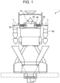
- the combination weighing apparatus 1 includes a distribution table 10, a radial feeder 20, a driver 30, a detector 40, a casing 50, a pool hopper 60, and a fixed member 70.
- the distribution table 10 serves as a distributor that receives articles from outside and distributes the articles downstream. As illustrated in Figs. 1 and 2 , the distribution table 10 is attached to the casing 50. Note that the casing 50 may house a motor that rotates the distribution table 10 or a vibrator that vibrates the distribution table 10.
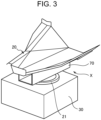
- the radial feeder 20 serves as a conveyor that receives an article from among the articles distributed by the distribution table 10 and conveys the article downstream.
- the radial feeder 20 may be of a type that conveys an article based on vibrations or may be of a type that conveys an article through a conveyor belt.
- the driver 30 drives the radial feeder 20.
- the driver 30 may be a vibrator that vibrates a vibration type of radial feeder 20 or may be a motor that drives a conveyor-belt type of radial feeder 20.
- the detector 40 is disposed below the conveyance face of the distribution table 10 or the conveyance face of the radial feeder 20.
- the detector 40 may be disposed inside the casing 50 disposed below the conveyance face of the distribution table 10.
- the detector 40 may be disposed below the conveyance face of the radial feeder 20 outside the casing 50.
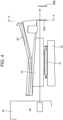
- the detector 40 detects an article that falls from the radial feeder 20 to the pool hopper 60.
- the detector 40 serves as a time-of-flight sensor that emits light, such as a laser beam or infrared light, and measures the time taken by the light to return back after being reflected by an article to detect the article.
- the detector 40 may be a photoelectric sensor including a light source that emits light and a photoreceiver that receives the light. In this case, the detector 40 detects the article, based on the light-receiving state of the photoreceiver.
- the detector 40 does not require disposing above an article being conveyed, so that deterioration in hygiene and contamination with foreign matter can be inhibited maximum.
- the combination weighing apparatus 1 enables observation of an article that falls from the radial feeder 20, different from a screw type of radial feeder, to the pool hopper 60.
- the fixed member 70 is disposed between the radial feeder 20 and the driver 30 and fastens the radial feeder 20 and the driver 30.
- the fixed member 70 is provided with a travel space 71 through which the light L described above travels.
- the fixed member 70 may be a hollow polygonal pillar-shaped member.
- the fixed member 70 is a hollow quadrangular pillar-shaped member.
- the height of the fixed member 70 may be changed depending on the characteristics of a photoelectric sensor serving as the detector 40.
- the radial feeder 20 is a radial feeder that conveys an article based on vibrations
- the travel space 71 of the pillar-shaped member is adjusted such that the light L is not blocked even when the pillar-shaped member vibrates due to such vibrations.
- the fixed member 70 is disposed below the radial feeder 20, the light L from the detector 40 can reach the end on the downstream side of the radial feeder 20.
- the fixed member 70 when viewed in the direction in which the light L is emitted, may be U-shaped with an upper opening.
- the pool hopper 60 has an inner wall 60A provided with a cutout 60X.
- the cutout 60X has a shape corresponding to the sectional shape of the fixed member 70 such that the light L having traveled through the travel space 71 of the fixed member 70 can reach an outer wall 60B that the pool hopper 60 has. Note that the outer wall 60B of the pool hopper 60 is provided with no cutout.
- the conveying apparatus 1 enables observation of the fall of an article from the radial feeder 20, with maximum inhibition of deterioration in hygiene and contamination with foreign matter.
- the present invention is not limited to the embodiments, and thus can be carried out in modified and altered aspects without departing from the gist and scope of the present invention in the claims.
- the distribution table 11 may repeat an arc motion and an up-and-down motion in a spiral manner within a certain angle range.
- the universal joint 40 has the spherical sliding bearing 41 as a bearing.
- a universal joint having two orthogonal shafts may be adopted.
- a bearing that bears a radial load may bear the second support shaft 53 such that the rod end 31 itself rotates freely around the vertical axis. Therefore, the present specification is exemplary and thus does not have any limitative meanings to the present invention.
Landscapes
- Physics & Mathematics (AREA)
- General Physics & Mathematics (AREA)
- Control Of Conveyors (AREA)
- Filling Or Emptying Of Bunkers, Hoppers, And Tanks (AREA)
- Discharge Of Articles From Conveyors (AREA)
Abstract
Description
- The present invention relates to a conveying apparatus.
- Conventionally, known has been a combination weighing apparatus in which a radial feeder is controlled based on observation of the fall of an article, from the leading end of a trough of the radial feeder, with a photoelectric sensor. In the combination weighing apparatus, the photoelectric sensor is disposed above the trough because of its function.
- Patent Literature 1:
JP 2020-094946 A - However, such a combination weighing apparatus including a photoelectric sensor disposed above a trough has the photoelectric sensor disposed above an article being conveyed. Thus, deterioration in hygiene or contamination with foreign matter is highly likely to occur. Furthermore, in particular, for perishables, such as raw chicken, to be weighed, as a problem, required is a structure for inhibiting contamination with foreign matter.
- Thus, the present invention has been made in consideration of the problems and an object of the present invention is to provide a conveying apparatus enabling observation of the fall of an article from a radial feeder, with maximum inhibition of deterioration in hygiene and contamination with foreign matter.
- A first aspect of the present invention is summarized as a conveying apparatus including: a distributor (10); a conveyor (20); a driver (30); and a detector (40), characterized in that the distributor (10) distributes articles from outside; the conveyor (20) receives an article from among the articles distributed by the distributor (10) and convey the article downstream; the driver (30) drives the conveyor (20); the detector (40) is disposed below a conveyance face of the distributor (10) or a conveyance face of the conveyor (20); and the detector (40) detects the article dropped from the conveyor (20), based on light emitted between the conveyor (20) and the driver (30).
- According to the present invention, it is possible to provide a conveying apparatus enabling observation of the fall of an article from a radial feeder, with maximum inhibition of deterioration in hygiene and contamination with foreign matter.
-
-
Fig. 1 is an explanatory view for an exemplary schematic entire configuration of a combination weighing apparatus (conveying apparatus) 1 according to an embodiment. -
Fig. 2 is a perspective view of part of the combination weighing apparatus (conveying apparatus) 1 according to the embodiment. -
Fig. 3 is a perspective view of an exemplary radial feeder (conveyor) 20 in the combination weighing apparatus (conveying apparatus) 1 according to the embodiment. -
Fig. 4 illustrates the radial feeder (conveyor) 20 inFig. 3 viewed in an X direction. -
Fig. 5 is a sectional view taken along line A-A ofFig. 4 . - Embodiments of the present invention will be described below based on the drawings. Note that the drawings are schematic and thus the parts are different in dimensions or ratio from the realities. In addition, parts between each drawing may be different in dimensions or ratio. Furthermore, in the present specification and the drawings, constituents substantially identical in function or configuration are denoted with the same reference signs and thus duplicate description thereof will be omitted. In addition, any constituents not directly related to the present invention are not illustrated.
- A conveying apparatus according to a first embodiment of the present invention will be described below with reference to
Figs. 1 to 5 . In the present embodiment, acombination weighing apparatus 1 will be described as an exemplary conveying apparatus. However, the present invention is not limited to this and thus can be applied to any other conveying apparatuses. For example, the present invention can be applied to a conveying apparatus that supplies articles to thecombination weighing apparatus 1. - As illustrated in
Fig. 1 , thecombination weighing apparatus 1 according to the present embodiment includes a distribution table 10, aradial feeder 20, adriver 30, adetector 40, acasing 50, apool hopper 60, and a fixedmember 70. - The distribution table 10 serves as a distributor that receives articles from outside and distributes the articles downstream. As illustrated in
Figs. 1 and2 , the distribution table 10 is attached to thecasing 50. Note that thecasing 50 may house a motor that rotates the distribution table 10 or a vibrator that vibrates the distribution table 10. - The
radial feeder 20 serves as a conveyor that receives an article from among the articles distributed by the distribution table 10 and conveys the article downstream. Theradial feeder 20 may be of a type that conveys an article based on vibrations or may be of a type that conveys an article through a conveyor belt. - The
driver 30 drives theradial feeder 20. For example, thedriver 30 may be a vibrator that vibrates a vibration type ofradial feeder 20 or may be a motor that drives a conveyor-belt type ofradial feeder 20. - The
detector 40 is disposed below the conveyance face of the distribution table 10 or the conveyance face of theradial feeder 20. For example, as illustrated inFigs. 1 and2 , thedetector 40 may be disposed inside thecasing 50 disposed below the conveyance face of the distribution table 10. Alternatively, thedetector 40 may be disposed below the conveyance face of theradial feeder 20 outside thecasing 50. - As illustrated in
Figs. 1 ,2 , and4 , based on light L emitted between theradial feeder 20 and thedriver 30, thedetector 40 detects an article that falls from theradial feeder 20 to thepool hopper 60. For example, thedetector 40 serves as a time-of-flight sensor that emits light, such as a laser beam or infrared light, and measures the time taken by the light to return back after being reflected by an article to detect the article. - The
detector 40 may be a photoelectric sensor including a light source that emits light and a photoreceiver that receives the light. In this case, thedetector 40 detects the article, based on the light-receiving state of the photoreceiver. - According to such a configuration, the
detector 40 does not require disposing above an article being conveyed, so that deterioration in hygiene and contamination with foreign matter can be inhibited maximum. According to such a configuration, thecombination weighing apparatus 1 enables observation of an article that falls from theradial feeder 20, different from a screw type of radial feeder, to the pool hopper 60. - As illustrated in
Figs. 3 to 5 , the fixedmember 70 is disposed between theradial feeder 20 and thedriver 30 and fastens theradial feeder 20 and thedriver 30. - As illustrated in
Fig. 5 , thefixed member 70 is provided with atravel space 71 through which the light L described above travels. For example, the fixedmember 70 may be a hollow polygonal pillar-shaped member. In the example ofFig. 5 , the fixedmember 70 is a hollow quadrangular pillar-shaped member. The height of the fixedmember 70 may be changed depending on the characteristics of a photoelectric sensor serving as thedetector 40. Furthermore, in a case where theradial feeder 20 is a radial feeder that conveys an article based on vibrations, thetravel space 71 of the pillar-shaped member is adjusted such that the light L is not blocked even when the pillar-shaped member vibrates due to such vibrations. - According to such a configuration, although the fixed
member 70 is disposed below theradial feeder 20, the light L from thedetector 40 can reach the end on the downstream side of theradial feeder 20. - Note that, as illustrated in
Fig. 5 , when viewed in the direction in which the light L is emitted, thefixed member 70 may be U-shaped with an upper opening. - As illustrated in
Fig. 5 , thepool hopper 60 has aninner wall 60A provided with acutout 60X. Thecutout 60X has a shape corresponding to the sectional shape of thefixed member 70 such that the light L having traveled through thetravel space 71 of thefixed member 70 can reach anouter wall 60B that thepool hopper 60 has. Note that theouter wall 60B of thepool hopper 60 is provided with no cutout. - The
conveying apparatus 1 according to the present embodiment enables observation of the fall of an article from theradial feeder 20, with maximum inhibition of deterioration in hygiene and contamination with foreign matter. - Some embodiments of the present invention have been described above. However, the present invention is not limited to the embodiments, and thus can be carried out in modified and altered aspects without departing from the gist and scope of the present invention in the claims. For example, instead of rotation of the distribution table 11, the distribution table 11 may repeat an arc motion and an up-and-down motion in a spiral manner within a certain angle range. The
universal joint 40 has the spherical sliding bearing 41 as a bearing. Instead of theuniversal joint 40, a universal joint having two orthogonal shafts may be adopted. Instead of the spherical sliding bearing 41 of the rod end 31, a bearing that bears a radial load may bear the second support shaft 53 such that the rod end 31 itself rotates freely around the vertical axis. Therefore, the present specification is exemplary and thus does not have any limitative meanings to the present invention. -
- 1
- Conveying apparatus (combination weighing apparatus)
- 10
- Distributor (distribution table)
- 20
- Conveyor (radial feeder)
- 30
- Driver
- 40
- Detector
- 50
- Casing
- 60
- Pool hopper
- 70
- Fixed member
- 71
- Travel space
Claims (4)
- A conveying apparatus comprising:a distributor (10);a conveyor (20);a driver (30); anda detector (40), characterized in thatthe distributor (10) distributes articles from outside;the conveyor (20) receives an article from among the articles distributed by the distributor (10) and convey the article downstream;the driver (30) drives the conveyor (20);the detector (40) is disposed below a conveyance face of the distributor (10) or a conveyance face of the conveyor (20); andthe detector (40) detects the article dropped from the conveyor (20), based on light emitted between the conveyor (20) and the driver (30).
- The conveying apparatus according to claim 1, characterized in that
the driver (30) includes a vibrator that vibrates the conveyor (20). - The conveying apparatus according to claim 1 or claim 2, further comprising a fixed member (70), characterized in thatthe fixed member (70) is disposed between the conveyor (20) and the driver (30);the fixed member (70) fastens the conveyor (20) and the driver (30); andthe fixed member (70) has a travel space (71) through which the light travels.
- The conveying apparatus according to claim 3, characterized in that
the fixed member (70) has an upper opening and is U-shaped in a case where the fixed member (70) is viewed in a direction in which the light is emitted.
Applications Claiming Priority (1)
| Application Number | Priority Date | Filing Date | Title |
|---|---|---|---|
| JP2023041386A JP2024131246A (en) | 2023-03-15 | 2023-03-15 | Conveyor |
Publications (2)
| Publication Number | Publication Date |
|---|---|
| EP4431884A1 true EP4431884A1 (en) | 2024-09-18 |
| EP4431884B1 EP4431884B1 (en) | 2026-01-21 |
Family
ID=90123439
Family Applications (1)
| Application Number | Title | Priority Date | Filing Date |
|---|---|---|---|
| EP24160393.5A Active EP4431884B1 (en) | 2023-03-15 | 2024-02-28 | Conveying apparatus |
Country Status (3)
| Country | Link |
|---|---|
| EP (1) | EP4431884B1 (en) |
| JP (1) | JP2024131246A (en) |
| DK (1) | DK4431884T3 (en) |
Citations (3)
| Publication number | Priority date | Publication date | Assignee | Title |
|---|---|---|---|---|
| US5270495A (en) * | 1992-02-28 | 1993-12-14 | Package Machinery Company | Combination weighing machine with feed control |
| JP2020094946A (en) | 2018-12-14 | 2020-06-18 | 大和製衡株式会社 | Combination weighing device |
| US10962403B2 (en) * | 2018-09-04 | 2021-03-30 | Ishida Co., Ltd. | Weighing device with an article supply conveyor that runs for different lengths of time depending on the detection of an article hanging from the end |
-
2023
- 2023-03-15 JP JP2023041386A patent/JP2024131246A/en active Pending
-
2024
- 2024-02-28 DK DK24160393.5T patent/DK4431884T3/en active
- 2024-02-28 EP EP24160393.5A patent/EP4431884B1/en active Active
Patent Citations (3)
| Publication number | Priority date | Publication date | Assignee | Title |
|---|---|---|---|---|
| US5270495A (en) * | 1992-02-28 | 1993-12-14 | Package Machinery Company | Combination weighing machine with feed control |
| US10962403B2 (en) * | 2018-09-04 | 2021-03-30 | Ishida Co., Ltd. | Weighing device with an article supply conveyor that runs for different lengths of time depending on the detection of an article hanging from the end |
| JP2020094946A (en) | 2018-12-14 | 2020-06-18 | 大和製衡株式会社 | Combination weighing device |
Also Published As
| Publication number | Publication date |
|---|---|
| JP2024131246A (en) | 2024-09-30 |
| DK4431884T3 (en) | 2026-03-02 |
| EP4431884B1 (en) | 2026-01-21 |
Similar Documents
| Publication | Publication Date | Title |
|---|---|---|
| US9073698B2 (en) | Transport section of a horizontal conveyor device with at least one adjustable guide element | |
| EP4431884B1 (en) | Conveying apparatus | |
| US20090090603A1 (en) | Automatic Belt Tracking System | |
| SE9704206D0 (en) | Device for handling empty beverage containers | |
| CN102015493A (en) | Device for conveying products | |
| US10230164B2 (en) | Antenna positioning mechanism | |
| US10533890B2 (en) | Combination weighing device including a hallow sensor cover and radiation compartments | |
| EP2772458A1 (en) | Rotary pipe-type linear feeder | |
| WO2020184632A1 (en) | Combination weighing device | |
| US6260425B1 (en) | Inspection machine for bottles or similar | |
| EP4359328B1 (en) | DEVICE FOR TURNING A SAMPLE CARRIER | |
| CN113414014A (en) | W-shaped single centrifugal centrifuge | |
| AU2020239758B2 (en) | A slip conveyor | |
| US20170211967A1 (en) | Combination weighing device | |
| JP2015189577A (en) | Supply device | |
| WO2021193080A1 (en) | Capsule mass measurement device | |
| US4462522A (en) | Vibratory conveyor | |
| DE59304653D1 (en) | Conveying device for dosing a bulk material | |
| KR102285279B1 (en) | Automatic Transfer Device for Conveyor Separation Section | |
| JP2018141680A (en) | Weighing device | |
| CN117664283B (en) | Automatic medicine weighing device for medicines with poor flowability | |
| GB2312522A (en) | Apparatus for weighing a flowable material | |
| Cokayne | The Way of the World: A Review of Current Practice in Automatic Parts Recognition, Feeding and Orientation | |
| EP4741317A1 (en) | Belt curve | |
| CN117177923B (en) | Conveyor and V-shaped conveyor mechanism including the conveyor |
Legal Events
| Date | Code | Title | Description |
|---|---|---|---|
| PUAI | Public reference made under article 153(3) epc to a published international application that has entered the european phase |
Free format text: ORIGINAL CODE: 0009012 |
|
| STAA | Information on the status of an ep patent application or granted ep patent |
Free format text: STATUS: REQUEST FOR EXAMINATION WAS MADE |
|
| 17P | Request for examination filed |
Effective date: 20240228 |
|
| AK | Designated contracting states |
Kind code of ref document: A1 Designated state(s): AL AT BE BG CH CY CZ DE DK EE ES FI FR GB GR HR HU IE IS IT LI LT LU LV MC ME MK MT NL NO PL PT RO RS SE SI SK SM TR |
|
| GRAP | Despatch of communication of intention to grant a patent |
Free format text: ORIGINAL CODE: EPIDOSNIGR1 |
|
| STAA | Information on the status of an ep patent application or granted ep patent |
Free format text: STATUS: GRANT OF PATENT IS INTENDED |
|
| RIC1 | Information provided on ipc code assigned before grant |
Ipc: G01G 19/393 20060101AFI20250730BHEP |
|
| INTG | Intention to grant announced |
Effective date: 20250808 |
|
| GRAS | Grant fee paid |
Free format text: ORIGINAL CODE: EPIDOSNIGR3 |
|
| GRAA | (expected) grant |
Free format text: ORIGINAL CODE: 0009210 |
|
| STAA | Information on the status of an ep patent application or granted ep patent |
Free format text: STATUS: THE PATENT HAS BEEN GRANTED |
|
| AK | Designated contracting states |
Kind code of ref document: B1 Designated state(s): AL AT BE BG CH CY CZ DE DK EE ES FI FR GB GR HR HU IE IS IT LI LT LU LV MC ME MK MT NL NO PL PT RO RS SE SI SK SM TR |
|
| REG | Reference to a national code |
Ref country code: CH Ref legal event code: F10 Free format text: ST27 STATUS EVENT CODE: U-0-0-F10-F00 (AS PROVIDED BY THE NATIONAL OFFICE) Effective date: 20260121 |
|
| REG | Reference to a national code |
Ref country code: DE Ref legal event code: R096 Ref document number: 602024002098 Country of ref document: DE |
|
| REG | Reference to a national code |
Ref country code: IE Ref legal event code: FG4D |
|
| REG | Reference to a national code |
Ref country code: DK Ref legal event code: T3 Effective date: 20260223 |
|
| REG | Reference to a national code |
Ref country code: NL Ref legal event code: MP Effective date: 20260121 |
|
| PG25 | Lapsed in a contracting state [announced via postgrant information from national office to epo] |
Ref country code: NL Free format text: LAPSE BECAUSE OF FAILURE TO SUBMIT A TRANSLATION OF THE DESCRIPTION OR TO PAY THE FEE WITHIN THE PRESCRIBED TIME-LIMIT Effective date: 20260121 |
|
| REG | Reference to a national code |
Ref country code: AT Ref legal event code: MK05 Ref document number: 1879063 Country of ref document: AT Kind code of ref document: T Effective date: 20260121 |
|
| PG25 | Lapsed in a contracting state [announced via postgrant information from national office to epo] |
Ref country code: RS Free format text: LAPSE BECAUSE OF FAILURE TO SUBMIT A TRANSLATION OF THE DESCRIPTION OR TO PAY THE FEE WITHIN THE PRESCRIBED TIME-LIMIT Effective date: 20260421 |
|
| PG25 | Lapsed in a contracting state [announced via postgrant information from national office to epo] |
Ref country code: ES Free format text: LAPSE BECAUSE OF FAILURE TO SUBMIT A TRANSLATION OF THE DESCRIPTION OR TO PAY THE FEE WITHIN THE PRESCRIBED TIME-LIMIT Effective date: 20260121 |
|
| PG25 | Lapsed in a contracting state [announced via postgrant information from national office to epo] |
Ref country code: PL Free format text: LAPSE BECAUSE OF FAILURE TO SUBMIT A TRANSLATION OF THE DESCRIPTION OR TO PAY THE FEE WITHIN THE PRESCRIBED TIME-LIMIT Effective date: 20260121 |
|
| PGFP | Annual fee paid to national office [announced via postgrant information from national office to epo] |
Ref country code: DK Payment date: 20260407 Year of fee payment: 3 |
|
| PG25 | Lapsed in a contracting state [announced via postgrant information from national office to epo] |
Ref country code: GR Free format text: LAPSE BECAUSE OF FAILURE TO SUBMIT A TRANSLATION OF THE DESCRIPTION OR TO PAY THE FEE WITHIN THE PRESCRIBED TIME-LIMIT Effective date: 20260422 |
|
| REG | Reference to a national code |
Ref country code: LT Ref legal event code: MG9D |
|
| PG25 | Lapsed in a contracting state [announced via postgrant information from national office to epo] |
Ref country code: LT Free format text: LAPSE BECAUSE OF FAILURE TO SUBMIT A TRANSLATION OF THE DESCRIPTION OR TO PAY THE FEE WITHIN THE PRESCRIBED TIME-LIMIT Effective date: 20260121 |
|
| PGFP | Annual fee paid to national office [announced via postgrant information from national office to epo] |
Ref country code: DE Payment date: 20260420 Year of fee payment: 3 |
|
| PG25 | Lapsed in a contracting state [announced via postgrant information from national office to epo] |
Ref country code: NO Free format text: LAPSE BECAUSE OF FAILURE TO SUBMIT A TRANSLATION OF THE DESCRIPTION OR TO PAY THE FEE WITHIN THE PRESCRIBED TIME-LIMIT Effective date: 20260421 |
|
| PG25 | Lapsed in a contracting state [announced via postgrant information from national office to epo] |
Ref country code: FI Free format text: LAPSE BECAUSE OF FAILURE TO SUBMIT A TRANSLATION OF THE DESCRIPTION OR TO PAY THE FEE WITHIN THE PRESCRIBED TIME-LIMIT Effective date: 20260121 Ref country code: SE Free format text: LAPSE BECAUSE OF FAILURE TO SUBMIT A TRANSLATION OF THE DESCRIPTION OR TO PAY THE FEE WITHIN THE PRESCRIBED TIME-LIMIT Effective date: 20260121 Ref country code: AT Free format text: LAPSE BECAUSE OF FAILURE TO SUBMIT A TRANSLATION OF THE DESCRIPTION OR TO PAY THE FEE WITHIN THE PRESCRIBED TIME-LIMIT Effective date: 20260121 |
|
| PG25 | Lapsed in a contracting state [announced via postgrant information from national office to epo] |
Ref country code: HR Free format text: LAPSE BECAUSE OF FAILURE TO SUBMIT A TRANSLATION OF THE DESCRIPTION OR TO PAY THE FEE WITHIN THE PRESCRIBED TIME-LIMIT Effective date: 20260121 |
|
| PG25 | Lapsed in a contracting state [announced via postgrant information from national office to epo] |
Ref country code: IS Free format text: LAPSE BECAUSE OF FAILURE TO SUBMIT A TRANSLATION OF THE DESCRIPTION OR TO PAY THE FEE WITHIN THE PRESCRIBED TIME-LIMIT Effective date: 20260521 Ref country code: PT Free format text: LAPSE BECAUSE OF FAILURE TO SUBMIT A TRANSLATION OF THE DESCRIPTION OR TO PAY THE FEE WITHIN THE PRESCRIBED TIME-LIMIT Effective date: 20260521 |
|
| PG25 | Lapsed in a contracting state [announced via postgrant information from national office to epo] |
Ref country code: LV Free format text: LAPSE BECAUSE OF FAILURE TO SUBMIT A TRANSLATION OF THE DESCRIPTION OR TO PAY THE FEE WITHIN THE PRESCRIBED TIME-LIMIT Effective date: 20260121 |
|
| PG25 | Lapsed in a contracting state [announced via postgrant information from national office to epo] |
Ref country code: BG Free format text: LAPSE BECAUSE OF FAILURE TO SUBMIT A TRANSLATION OF THE DESCRIPTION OR TO PAY THE FEE WITHIN THE PRESCRIBED TIME-LIMIT Effective date: 20260121 |