EP4431877A1 - Positionsmesseinrichtung mit permanentmagneten - Google Patents
Positionsmesseinrichtung mit permanentmagneten Download PDFInfo
- Publication number
- EP4431877A1 EP4431877A1 EP23162285.3A EP23162285A EP4431877A1 EP 4431877 A1 EP4431877 A1 EP 4431877A1 EP 23162285 A EP23162285 A EP 23162285A EP 4431877 A1 EP4431877 A1 EP 4431877A1
- Authority
- EP
- European Patent Office
- Prior art keywords
- permanent magnet
- sensor field
- measuring device
- graduation track
- position measuring
- Prior art date
- Legal status (The legal status is an assumption and is not a legal conclusion. Google has not performed a legal analysis and makes no representation as to the accuracy of the status listed.)
- Granted
Links
Images

Classifications
-
- G—PHYSICS
- G01—MEASURING; TESTING
- G01B—MEASURING LENGTH, THICKNESS OR SIMILAR LINEAR DIMENSIONS; MEASURING ANGLES; MEASURING AREAS; MEASURING IRREGULARITIES OF SURFACES OR CONTOURS
- G01B7/00—Measuring arrangements characterised by the use of electric or magnetic techniques
- G01B7/003—Measuring arrangements characterised by the use of electric or magnetic techniques for measuring position, not involving coordinate determination
-
- G—PHYSICS
- G01—MEASURING; TESTING
- G01B—MEASURING LENGTH, THICKNESS OR SIMILAR LINEAR DIMENSIONS; MEASURING ANGLES; MEASURING AREAS; MEASURING IRREGULARITIES OF SURFACES OR CONTOURS
- G01B7/00—Measuring arrangements characterised by the use of electric or magnetic techniques
- G01B7/02—Measuring arrangements characterised by the use of electric or magnetic techniques for measuring length, width or thickness
-
- G—PHYSICS
- G01—MEASURING; TESTING
- G01B—MEASURING LENGTH, THICKNESS OR SIMILAR LINEAR DIMENSIONS; MEASURING ANGLES; MEASURING AREAS; MEASURING IRREGULARITIES OF SURFACES OR CONTOURS
- G01B7/00—Measuring arrangements characterised by the use of electric or magnetic techniques
- G01B7/30—Measuring arrangements characterised by the use of electric or magnetic techniques for measuring angles or tapers; for testing the alignment of axes
-
- G—PHYSICS
- G01—MEASURING; TESTING
- G01D—MEASURING NOT SPECIALLY ADAPTED FOR A SPECIFIC VARIABLE; ARRANGEMENTS FOR MEASURING TWO OR MORE VARIABLES NOT COVERED IN A SINGLE OTHER SUBCLASS; TARIFF METERING APPARATUS; MEASURING OR TESTING NOT OTHERWISE PROVIDED FOR
- G01D5/00—Mechanical means for transferring the output of a sensing member; Means for converting the output of a sensing member to another variable where the form or nature of the sensing member does not constrain the means for converting; Transducers not specially adapted for a specific variable
- G01D5/12—Mechanical means for transferring the output of a sensing member; Means for converting the output of a sensing member to another variable where the form or nature of the sensing member does not constrain the means for converting; Transducers not specially adapted for a specific variable using electric or magnetic means
- G01D5/14—Mechanical means for transferring the output of a sensing member; Means for converting the output of a sensing member to another variable where the form or nature of the sensing member does not constrain the means for converting; Transducers not specially adapted for a specific variable using electric or magnetic means influencing the magnitude of a current or voltage
- G01D5/142—Mechanical means for transferring the output of a sensing member; Means for converting the output of a sensing member to another variable where the form or nature of the sensing member does not constrain the means for converting; Transducers not specially adapted for a specific variable using electric or magnetic means influencing the magnitude of a current or voltage using Hall-effect devices
- G01D5/145—Mechanical means for transferring the output of a sensing member; Means for converting the output of a sensing member to another variable where the form or nature of the sensing member does not constrain the means for converting; Transducers not specially adapted for a specific variable using electric or magnetic means influencing the magnitude of a current or voltage using Hall-effect devices influenced by the relative movement between the Hall device and magnetic fields
-
- G—PHYSICS
- G01—MEASURING; TESTING
- G01D—MEASURING NOT SPECIALLY ADAPTED FOR A SPECIFIC VARIABLE; ARRANGEMENTS FOR MEASURING TWO OR MORE VARIABLES NOT COVERED IN A SINGLE OTHER SUBCLASS; TARIFF METERING APPARATUS; MEASURING OR TESTING NOT OTHERWISE PROVIDED FOR
- G01D5/00—Mechanical means for transferring the output of a sensing member; Means for converting the output of a sensing member to another variable where the form or nature of the sensing member does not constrain the means for converting; Transducers not specially adapted for a specific variable
- G01D5/12—Mechanical means for transferring the output of a sensing member; Means for converting the output of a sensing member to another variable where the form or nature of the sensing member does not constrain the means for converting; Transducers not specially adapted for a specific variable using electric or magnetic means
- G01D5/244—Mechanical means for transferring the output of a sensing member; Means for converting the output of a sensing member to another variable where the form or nature of the sensing member does not constrain the means for converting; Transducers not specially adapted for a specific variable using electric or magnetic means influencing characteristics of pulses or pulse trains; generating pulses or pulse trains
- G01D5/24428—Error prevention
- G01D5/24433—Error prevention by mechanical means
- G01D5/24438—Special design of the sensing element or scale
-
- G—PHYSICS
- G01—MEASURING; TESTING
- G01D—MEASURING NOT SPECIALLY ADAPTED FOR A SPECIFIC VARIABLE; ARRANGEMENTS FOR MEASURING TWO OR MORE VARIABLES NOT COVERED IN A SINGLE OTHER SUBCLASS; TARIFF METERING APPARATUS; MEASURING OR TESTING NOT OTHERWISE PROVIDED FOR
- G01D5/00—Mechanical means for transferring the output of a sensing member; Means for converting the output of a sensing member to another variable where the form or nature of the sensing member does not constrain the means for converting; Transducers not specially adapted for a specific variable
- G01D5/12—Mechanical means for transferring the output of a sensing member; Means for converting the output of a sensing member to another variable where the form or nature of the sensing member does not constrain the means for converting; Transducers not specially adapted for a specific variable using electric or magnetic means
- G01D5/244—Mechanical means for transferring the output of a sensing member; Means for converting the output of a sensing member to another variable where the form or nature of the sensing member does not constrain the means for converting; Transducers not specially adapted for a specific variable using electric or magnetic means influencing characteristics of pulses or pulse trains; generating pulses or pulse trains
- G01D5/245—Mechanical means for transferring the output of a sensing member; Means for converting the output of a sensing member to another variable where the form or nature of the sensing member does not constrain the means for converting; Transducers not specially adapted for a specific variable using electric or magnetic means influencing characteristics of pulses or pulse trains; generating pulses or pulse trains using a variable number of pulses in a train
- G01D5/2454—Encoders incorporating incremental and absolute signals
- G01D5/2455—Encoders incorporating incremental and absolute signals with incremental and absolute tracks on the same encoder
Definitions
- the invention relates to a position measuring device for measuring a relative angular or linear position between a detection and scale element using permanent magnets according to claim 1.
- the invention is based on the object of creating a position measuring device which combines high measuring accuracy and economical production.
- the position measuring device comprises a detection element, for example a scanning head of an angle or length measuring device, and a scale element that can be moved relative to the detection element along a first direction (x), for example a magnetic graduation drum or measuring tape of an angle or length measuring device.
- the scale element has a first and a second graduation track, both of which are absolute, and a third incremental graduation track, wherein the three graduation tracks run or are arranged parallel to one another and spaced apart in a second direction (y).
- the detection element comprises at least a first sensor field that is arranged offset in a third direction (z) with respect to the first graduation track, so that a third air gap is formed between the first sensor field and the first graduation track.
- the detection element further comprises a second sensor field that is arranged offset in the third direction (z) with respect to the second graduation track.
- the third air gap is formed between the second sensor field and the second graduation track.
- the detection element also comprises a third sensor field, which is arranged offset in the third direction (z) relative to the third graduation track, so that the third air gap is also formed between the third sensor field and the third graduation track.
- the sensor fields are designed and arranged in such a way that at least the graduation track opposite the respective sensor field in the third direction (z) can be scanned.
- the detection element comprises a first permanent magnet, for example in the form of a cuboid bar magnet.
- the first permanent magnet is arranged opposite the first graduation track and for this purpose in the third direction (z) so that the first sensor field is arranged between the first permanent magnet and the first graduation track.
- a second air gap can be formed between the first sensor field and the first permanent magnet.
- a second permanent magnet for example in the form of a cuboid bar magnet, is arranged opposite the second graduation track and offset therefrom in the third direction (z).
- the second permanent magnet is also arranged offset in the third direction (z) so that the second sensor field lies between the second graduation track and the second permanent magnet.
- the second air gap can also be formed between the second sensor field and the second permanent magnet.
- a first air gap can be formed in the second direction (y) between the first and second permanent magnets.
- the sensor fields are therefore arranged offset in a third direction (z) to the respective graduation track to be scanned and are arranged opposite the respective graduation track to be scanned.
- the first and second graduation tracks are absolute, which means that the current absolute position value is always determined by the detection element as soon as the position measuring device is in operation.
- the third incremental graduation track is scanned by the detection element, whereby a comparatively fine incremental position is determined.
- the absolute position value is linked to the incremental position.
- the three graduation tracks run parallel to one another along the first direction (x) and are arranged at a distance from one another in a second direction (y).
- the position measuring device achieves a high measurement accuracy, in particular by minimizing measurement deviations such as interpolation or reversal errors.
- An air gap is the space or distance between two opposing surfaces that can carry a magnetic flux.
- the air gap can be air, any other solid or any other gas, gas mixture or combination. of these which interact almost non-ferromagnetically, e.g. an aluminum alloy.
- the first, second and third air gaps can also consist of different materials.
- the first air gap and the second air gap can consist of an aluminum alloy and the third air gap can consist of air.
- the sensor fields used in the position measuring device according to the invention can be designed as magnet-sensitive structures which are applied to one and the same flat substrate (for example a glass substrate). Alternatively, a separate flat substrate can be provided for each sensor field. These sensor fields can consist of several ferromagnetic metal strips, for example made of permalloy. The magnetic fields of the scale element influence the magnetization of the metal strips, which changes the electrical resistance (magnetoresistive effect). These position-dependent resistance values are output as position information after electronic processing of the sensor signals generated by the sensor fields in an evaluation electronics.
- the sensor fields experience a defined pre-magnetization, which counteracts the formation of magnetic domains in the metal strips.
- the coordinate system described here is a Cartesian coordinate system, i.e. the first direction (x) is orthogonal to the second direction (y) and the third direction (z) is in turn oriented orthogonally to the other two directions (x and y).
- the third graduation track can be arranged between the first graduation track and the second graduation track in relation to the second direction (y).
- the advantage here is that the two permanent magnets, which are arranged offset from the first and second graduation tracks in the third direction (z), have a Pre-magnetization can be applied to all sensor fields used in the detection element. An additional permanent magnet above the third graduation track or the third sensor field is not required.
- the scale element can be formed, for example, by a method in which a magnetic material is applied into or onto the surface of a carrier element, for example a metal carrier element with a rectangular cross-sectional shape.
- the graduation tracks can then be produced by local magnetization according to a predetermined exact pattern.
- the position measuring device is configured such that the magnetization direction of the two permanent magnets is identical, which can lead to the formation of a magnetic field with a homogeneous component in at least one plane of the first and second directions (x,y planes) above and/or below and/or between the two permanent magnets, for example with an offset of the permanent magnets in the second direction (y).
- the magnetization direction of the two permanent magnets can be designed such that the north pole of the first permanent magnet and the south pole of the second permanent magnet are opposite each other.
- the south pole of the first permanent magnet and the north pole of the second permanent magnet can also be opposite each other.
- a homogeneous region is understood to be at least a partial region of a magnetic field in which the field lines in at least one plane (for example the x,y plane) all run parallel and in the same direction (for example in the y direction).
- the third sensor field can be arranged such that it is still located in a homogeneous region of the magnetic field B between the first and second permanent magnets, but without lying in a plane (x,y plane) with the first and second sensor fields.
- the two permanent magnets can be arranged parallel to one another so that the pole alignment of the permanent magnets (direction of the connecting line between the north and south poles) each has a directional component perpendicular to the measuring direction (x-direction).
- the long edges of the two permanent magnets can run along the measuring direction (x-direction).
- the sensor fields can also be arranged parallel to one another in the measuring direction (x-direction) so that their long edges run along the measuring direction (x-direction).
- the secondary edges which define the height of the permanent magnets or sensor fields advantageously run parallel to the third direction (z).
- the secondary edges which define the width of the permanent magnets or sensor fields can run parallel to the second direction (y).
- the first permanent magnet can be arranged offset from the first graduation track in the third direction (z) such that the first sensor field lies between the first graduation track and the first permanent magnet in relation to the third direction (z).
- the second permanent magnet can be arranged offset from the second graduation track in the third direction (z) such that the second sensor field lies between the first graduation track and the second permanent magnet in relation to the third direction (z).
- one permanent magnet is arranged centrally above each sensor field.
- a second air gap can be formed between the first permanent magnet and the first sensor field in the third direction (z). Additionally or alternatively, a second air gap can be formed between the second permanent magnet and the second sensor field in the third direction (z).
- the first permanent magnet and the second permanent magnet can lie in one plane (x,y plane).
- the first sensor field and the second sensor field can also lie in a further plane (x,y plane), so that the second air gap in the third direction (z) is formed identically between the first sensor field and the first permanent magnet and between the second sensor field and the second permanent magnet.
- the first permanent magnet can be arranged on the back of the substrate above the first sensor field.
- the second permanent magnet can be arranged on the back of the substrate above the second sensor field.
- a detachable or fixed connection can be provided between a permanent magnet and the substrate, for example an adhesive connection.
- the back side of the substrate is understood to mean the part of the substrate surface which is opposite the surface in the third direction (z) which faces the graduation tracks.
- At least one of the two permanent magnets can be designed as a bar magnet.
- the longitudinal edges can define the length X PM and the secondary edges the width Y PM and the height Z PM .
- a permanent magnet is a magnet made of a semi-hard or hard magnetic material, for example an alloy of iron, cobalt, nickel or certain ferrites.
- the magnetic field of a permanent magnet is a static magnetic field.
- a permanent magnet has one or more north and south poles on its surface.
- the sensor fields can also be approximately described as cuboids, where the long edges define the length Xs and the side edges define the width Ys and the height Zs.
- the two permanent magnets can be dimensioned in length, width and height, and alternatively or additionally the first air gap can be dimensioned in the second direction (y) and alternatively or additionally the second air gap can be dimensioned in the third Direction (z) must be dimensioned such that at least in the region of the sensor fields the magnetic field forms homogeneous regions at least in one plane of the first and second direction (x,y plane). It is advantageous here that the homogeneous regions of the magnetic field can lead to a pre-magnetization of the sensor fields in the direction of the second direction, which counteracts the formation of magnetic domains in the metal strips of the sensor fields.
- the geometries of the individual permanent magnets, the choice of the energy product of the individual permanent magnets and the first and, additionally or alternatively, the second air gap can be used as control variables for influencing the local position of the homogeneous areas.
- the first permanent magnet can be dimensioned in particular in the first direction (x) and additionally or alternatively in the second direction (y) such that it protrudes beyond the dimensions of the first sensor field.
- the second permanent magnet can be dimensioned in particular in the first direction (x) and in the second direction (y) such that it protrudes beyond the dimensions of the second sensor field.
- the dimensions of a sensor field are those edges that define the length and width of the sensor field. Otherwise, it means the edge(s) of the orthogonal projection (in the third direction z) of the sensor field area onto the plane (x,y plane) in which the permanent magnet is located.
- the first permanent magnet can be dimensioned such that only its dimension in the second direction (y) is larger than the dimensions of the first sensor field in the second direction (y).
- the second permanent magnet can also or only be dimensioned such that only its dimension in the second direction (y) is larger than the dimensions of the second sensor field in the second direction (y).
- the two permanent magnets can be geometrically identical, i.e. the design, the cross-sectional shape and the edge length of the first permanent magnet and the second permanent magnet are the same.
- the two permanent magnets can have an identical energy product, i.e. the energy product of the first permanent magnet and the energy product of the second permanent magnet have the same amount.
- the energy product of a permanent magnet is the maximum product of magnetic flux density and magnetic field strength that can simultaneously exist in the material of a permanent magnet.
- the dimension of the first air gap in the second direction (y) is dimensioned such that it corresponds at least to the dimension of the third sensor field in the second direction (y).
- the scale element can have at least one further graduation track, which is designed incrementally.
- the further graduation track can also be arranged between the first and second graduation tracks, so that the first, second, third and the further graduation tracks are arranged parallel and spaced apart in a second direction (y).
- At least one further sensor field can also be arranged opposite the further graduation track in the third direction (z).
- the sensor fields in the detection element are designed in such a way that the graduation tracks can be scanned by them.
- the first permanent magnet is arranged offset from the first graduation track in the third direction (z) in such a way that the first sensor field lies between the first graduation track and the first permanent magnet.
- the second permanent magnet is arranged offset from the second graduation track in the third direction (z) in such a way that the second sensor field lies between the first graduation track and the second permanent magnet.
- the magnetic field between the first and second permanent magnets is designed in such a way that at least the third sensor field and the further sensor field lie in a region of the magnetic field with homogeneous field line components with respect to at least one plane of the first and second direction (x,y planes) and can be penetrated by the magnetic field formed.
- the first sensor field, the second sensor field, the third sensor field and the further sensor field can lie in one plane (x,y plane).
- the first and second sensor fields lie in a first plane (x,y plane) and the third and further sensor fields lie in a second plane (x,y plane).
- the first plane differs from the second plane with respect to its position in the third direction (z).
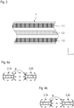
- FIG.1 a position measuring device according to the invention, designed as an angle measuring device, comprising a scale element 1 and a detection element 2.
- the two main components of the position measuring device are arranged at a distance from one another in a third direction z and are mechanically coupled, for example, to two machine elements which can move relative to one another in a rotational manner along a first direction x, wherein their relative or absolute position (angular position or linear position) is detected.
- the position measuring device comprises a scale element 1 with a first graduation track 1.1, a second graduation track 1.2 and a third graduation track 1.3.
- the position measuring device also comprises a detection element 2, which comprises at least a first sensor field 2.1, at least a second sensor field 2.2 and at least a third sensor field 2.3.
- the sensor fields 2.1, 2.2, 2.3 can be designed as magnet-sensitive structures which are applied to one and the same flat substrate 4 (for example a glass substrate).
- the detection element 2 comprises a first permanent magnet 2.10 and a second permanent magnet 2.20 as well as evaluation electronics (not shown).
- the three sensor fields 2.1, 2.2, 2.3 function according to the magnetoresistive principle, with a layer sensitive to magnetic fields facing the scale element 1.
- the three sensor fields 2.1, 2.2, 2.3 are arranged offset in the third direction z with respect to the graduation tracks 1.1, 1.2, 1.3, so that a third air gap L 3 is formed.
- the sensor fields 2.1, 2.2, 2.3 are advantageously arranged such that the third air gap L 3 is formed over the surface of the magnetically sensitive layer with an approximately constant dimension in the third direction z.
- the dimensions of the third air gap L 3 can vary between the individual sensor surfaces and the graduation tracks below.
- the first permanent magnet 2.10 is arranged offset from the first graduation track 1.1 in the third direction z, so that it is arranged opposite the back of the substrate 4 in the region of the first sensor field 2.1.
- a second air gap L 2 can be formed between the first sensor field 2.1 and the first permanent magnet 2.10.
- the second permanent magnet 2.20 is arranged offset from the second graduation track 1.2 in the third direction z, so that it is arranged opposite the back of the second sensor field 2.2.
- the second air gap L 2 can also be formed between the second sensor field 2.2 and the second permanent magnet 2.20.
- a first air gap L 1 is located in the second direction y between the first permanent magnet 2.10 and the second permanent magnet.
- the scale element 1 comprises three graduation tracks 1.1, 1.2, 1.3, according to a first embodiment of the invention, two of which are absolute and one incremental.
- the scale element 1 is advantageously designed such that the third graduation track 1.3 is arranged between the first graduation track 1.1 and the second graduation track.
- the first and second graduation tracks 1.1, 1.2 of the scale element 1 each have at least one absolute magnetic code graduation, which can be designed, for example, such that it has areas with a magnetic north pole and areas with a magnetic south pole at irregular intervals, which individually or combined form predefined position information, e.g. in the form of a Pseudorandom sequence.
- the third graduation track 1.3 of the scale element 1 has at least one relatively fine incremental magnetic code graduation, which can be formed, for example, by means of alternating north and south poles at regular intervals from one another.
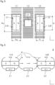
- the Figures 4a, 4b show the magnetization directions of the permanent magnets 2.10, 2.20 of the position measuring device according to the invention.
- the permanent magnets 2.10, 2.20 are arranged in such a way that the magnetization direction of the two permanent magnets is identical and the resulting magnetic field B is formed at least in partial areas with a homogeneous component with respect to at least one plane of the first and second direction (x,y planes) and in the second direction (y direction).
- Fig.5 shows the position measuring device according to the invention according to the first embodiment in plan view.
- the first permanent magnet 2.10 is arranged centrally in the first direction x and centrally in the second direction y with respect to the first sensor field 2.1 (shown in dashed lines) and the second permanent magnet 2.20 is analogously arranged centrally in the first direction x and centrally in the second direction y with respect to the second sensor field 2.2 (shown in dashed lines).
- the two permanent magnets 2.10, 2.20 are dimensioned such that they protrude over the sensor fields 2.1, 2.2, ie in particular the external dimensions of the permanent magnets 2.10, 2.20 in length X PM and width Y PM are larger than the length Xs and width Ys of the sensor fields below 2.1, 2.2.
- the two permanent magnets 2.10, 2.20 can be designed such that only one of the dimensions (length X PM , width Y PM ) is larger than the corresponding dimension of the sensor field arranged underneath (length Xs, width Ys). The remaining dimension can be either identical or smaller than is the case with the sensor field arranged underneath.
- the two permanent magnets 2.10, 2.20 as well as the sensor fields 2.1, 2.2, 2.3 arranged underneath are aligned such that their longitudinal edges (length X PM or Xs) run parallel along the first direction x and the secondary edges (height Z PM or Zs) run parallel to the third direction z.
- a magnetic field B with characteristic field line courses is formed between the first and second permanent magnets 2.10, 2.20, indicated by magnetic field vectors.
- the magnetic field forms approximately homogeneous areas in at least one plane of the first and second direction (x,y planes), characterized by magnetic field vectors with a course in the second direction y.
- the sensor fields 2.1, 2.2, 2.3 are advantageously arranged relative to the permanent magnets in such a way that they lie in the effective range of the magnetic field B.
- the first permanent magnet 2.10 is arranged in the third direction z offset from the first sensor field 2.1, so that it is located in a region of at least one plane of the first and second directions (x,y planes) of the magnetic field B with an approximately homogeneous field line course with a direction vector in the second direction y (y direction).
- the second permanent magnet 2.20 is arranged in the third direction z offset from the second sensor field 2.2, so that it is also located in a region of at least one plane of the first and second directions (x,y planes) of the magnetic field B with an approximately homogeneous field line course with a direction vector in the second direction y (y direction).
- the third sensor field 2.3 is arranged in such a way that it is in a plane with the first and second sensor fields 2.1, 2.2 and between them, so that it also lies in an area of at least one plane of the first and second directions x, y (x,y planes) of the magnetic field B with an approximately homogeneous field line course with a direction vector in the second direction y (y direction).
- the geometries of the individual permanent magnets 2.10, 2,20, the choice of the energy product of the individual permanent magnets 2.10, 2,20 and the first air gap L 1 and additionally or alternatively the second air gap L 2 can be used as control variables for influencing the local position of the homogeneous areas.
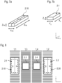
- the first permanent magnet 2.10 can be shaped as a bar magnet with a rectangular cross-section, wherein the longitudinal edges define the length X PM and the secondary edges the width Y PM and the height Z PM .
- the second permanent magnet 2.20 can be designed identically to the first permanent magnet 2.10, wherein the longitudinal edges also define the length X PM and the secondary edges the width Y PM and the height Z PM of the second permanent magnet 2.20.
- the sensor fields 1.1, 1.2, 1.3 can be used according to the Figure 7b can be approximately described as a cuboid, where the long edges define the length X S and the side edges define the width Y S and the height Z S.
- Fig.8 shows a second embodiment of the position measuring device according to the invention, which provides at least one further graduation track 1.4 between the first graduation track 1.1 and the second graduation track 1.2 and next to the third graduation track 1.3, which is designed incrementally and wherein at least one further sensor field 2.4 is arranged in the third direction z opposite the at least one further graduation track 1.4.
- the magnetic field B between the first and second permanent magnets 2.10, 2.20 is designed such that both the third sensor field 2.3 and the further sensor field 2.4 in a region of at least one plane of the first and second directions x, y (x,y planes) of the magnetic field B with a homogeneous field line course with a direction vector in the second direction y (y direction) and can be penetrated by the magnetic field B formed.
- the first sensor field 2.1, the second sensor field 2.2, the third sensor field 2.3 and the further sensor field 2.4 can lie in one plane (x,y plane).
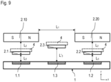
- the sensor fields 2.1, 2.2 can be arranged in the third direction z relative to one another, so that the first sensor field 2.1 is arranged between the first graduation track 1.1 and the first permanent magnet 2.10, and the second sensor field 2.2 is arranged between the second graduation track 1.2 and the second permanent magnet 2.20, wherein the first and second sensor fields 2.1, 2.2 lie in one plane (x,y plane).
- the sensor fields 2.1, 2.2, 2.3 are designed as magnet-sensitive structures, wherein a separate flat substrate 4 was used for each sensor field 2.1, 2.2, 2.3.
- the same substrate 4 can also be provided for the first and second sensor fields 2.1, 2.2, which then extends flat in one plane (x,y plane) (not shown).
- a third air gap L 3 is formed between the first graduation track 1.1 and the first sensor field 2.1 and additionally or alternatively between the second graduation track 1.2 and the second sensor field 2.2.
- the third sensor field 2.3 is arranged offset in the third direction z to the third graduation track 1.3, but is not in the same plane (x,y plane) as the first and second sensor fields 2.1, 2.2.
- the third air gap L' 3 is formed between the third graduation track 1.3 and the third sensor field 2.3.
- the third sensor field 2.3 is advantageously arranged such that it lies in a homogeneous region of at least one plane of the first and second directions x, y (x,y planes) of the magnetic field B between the first and second permanent magnets 2.10, 2.20 with a direction vector in the second direction y (y direction).
Landscapes
- Physics & Mathematics (AREA)
- General Physics & Mathematics (AREA)
- Measurement Of Length, Angles, Or The Like Using Electric Or Magnetic Means (AREA)
- Transmission And Conversion Of Sensor Element Output (AREA)
Abstract
Description
- Die Erfindung betrifft eine Positionsmesseinrichtung zur Messung einer relativen Winkel- oder Linearposition zwischen einem Detektions- und Skalenelement unter Verwendung von Permanentmagneten gemäß dem Anspruch 1.
- Aus der Patentschrift
EP 2 053 362 A2 ist eine Positionsmesseinrichtung umfassend eine absolute und zwei inkrementelle Teilungsspuren bekannt. Mittels magnetoresistiver Sensoren wird die Bestimmung einer Positionsinformation ermöglicht, insbesondere unter Einsatz dreier gestapelter Vormagnetisierungselemente mit differenzierenden Polarisationsrichtungen. Nachteilhaft an der Positionsmesseinrichtung im Stand der Technik sind die höheren Material- und Montagekosten durch den Einsatz von drei Vormagnetisierungselementen. - Der Erfindung liegt die Aufgabe zugrunde eine Positionsmesseinrichtung zu schaffen, welche eine hohe Messgenauigkeit und eine wirtschaftliche Herstellung vereint.
- Diese Aufgabe wird erfindungsgemäß durch die Merkmale des Anspruches 1 gelöst. Vorteilhafte Ausgestaltungen und Weiterbildungen sind in den jeweils abhängigen Ansprüchen angegeben.
- Die erfindungsgemäße Positionsmesseinrichtung umfasst ein Detektionselement, etwa einen Abtastkopf einer Winkel- oder Längenmesseinrichtung, und ein relativ zum Detektionselement entlang einer ersten Richtung (x) bewegbares Skalenelement, beispielsweise eine magnetische Teilungstrommel oder Maßband einer Winkel- oder Längenmesseinrichtung. Das Skalenelement weist eine erste und eine zweite Teilungsspur auf, welche beide absolut ausgebildet sind, sowie eine dritte inkrementelle Teilungsspur, wobei die drei Teilungsspuren zueinander parallel und in einer zweiten Richtung (y) beabstandet verlaufen bzw. angeordnet sind. Das Detektionselement umfasst wenigstens ein erstes Sensorfeld, das versetzt in einer dritten Richtung (z) gegenüber der ersten Teilungsspur angeordnet ist, sodass ein dritter Luftspalt zwischen dem ersten Sensorfeld und der ersten Teilungsspur ausgebildet ist. Das Detektionselement umfasst ferner ein zweites Sensorfeld, das versetzt in der dritten Richtung (z) gegenüber der zweiten Teilungsspur angeordnet ist. Zwischen dem zweiten Sensorfeld und der zweiten Teilungsspur ist der dritte Luftspalt ausgebildet. Das Detektionselement umfasst noch ein drittes Sensorfeld, das versetzt in der dritten Richtung (z) gegenüber der dritten Teilungsspur angeordnet ist, sodass ebenfalls der dritte Luftspalt zwischen dem dritten Sensorfeld und der dritten Teilungsspur ausgebildet ist. Die Sensorfelder sind so ausgestaltet und angeordnet, dass wenigstens die dem jeweiligen Sensorfeld in der dritten Richtung (z) gegenüber liegende Teilungsspur abtastbar ist. Zusätzlich umfasst das Detektionselement einen ersten Permanentmagnet, etwa in Form eines quaderförmigen Stabmagneten. Der erste Permanentmagnet ist dabei gegenüber der ersten Teilungsspur und hierzu derart in der dritten Richtung (z) versetzt angeordnet, dass zwischen dem ersten Permanentmagnet und der ersten Teilungsspur das erste Sensorfeld angeordnet ist. Ein zweiter Luftspalt kann dabei zwischen dem ersten Sensorfeld und dem ersten Permanentmagnet ausgebildet sein. Ein zweiter Permanentmagnet, etwa in Form eines quaderförmigen Stabmagneten, ist gegenüber der zweiten Teilungsspur und hierzu in der dritten Richtung (z) versetzt angeordnet. Dabei ist der zweite Permanentmanget ebenfalls so in der dritten Richtung (z) versetzt angeordnet, dass das zweite Sensorfeld zwischen der zweiten Teilungsspur und dem zweiten Permanentmagneten liegt. Auch zwischen dem zweiten Sensorfeld und dem zweiten Permanentmagnet kann der zweite Luftspalt ausgebildet sein. Zusätzlich kann ein erster Luftspalt in der zweiten Richtung (y) zwischen dem ersten und zweiten Permanentmagnet ausgebildet sein.
- Die Sensorfelder sind also in einer dritten Richtung (z) versetzt zur jeweilig abzutastenden Teilungsspur angeordnet und zur jeweilig abzutastenden Teilungsspur gegenüber liegend angeordnet.
- Die erste und die zweite Teilungsspur sind absolut ausgebildet, das heißt, dass durch das Detektionselement immer der aktuelle absolute Positionswert bestimmt wird, sobald die Positionsmesseinrichtung in Betrieb ist. Zudem wird durch das Detektionselement die dritte inkrementelle Teilungsspur abgetastet, wobei hierdurch eine vergleichsweise feine Inkrementalposition bestimmt wird. Zur Erhöhung der Auflösung beziehungsweise der Messgenauigkeit wird der absolute Positionswert mit der Inkrementalposition verknüpft. Die drei Teilungsspuren verlaufen zueinander parallel entlang der ersten Richtung (x) und sind in einer zweiten Richtung (y) beabstandet zueinander angeordnet.
- Auf diese Weise erreicht die erfindungsgemäße Positionsmesseinrichtung eine hohe Messgenauigkeit, insbesondere durch die Minimierung von Messabweichungen wie beispielsweise Interpolations- oder Umkehrfehlern.
- Unter einem Luftspalt ist der Raum bzw. Abstand zu verstehen, der zwischen zwei gegenüberliegenden Flächen eingenommen wird, welche einen magnetischen Fluss führen können. Der Luftspalt kann dabei neben Luft auch jeden anderen Feststoff bzw. jedes andere Gas, Gasgemisch oder Kombinationen hiervon aufweisen, welche annähernd nicht ferromagnetisch wechselwirken, z.B. auch eine Aluminiumlegierung. Der erste, zweite und dritte Luftspalt können hierbei auch aus unterschiedlichen Materialien bestehen. So können beispielsweise der erste Luftspalt und der zweite Luftspalt aus einer Aluminiumlegierung und der dritte Luftspalt aus Luft bestehen.
- Die in der erfindungsgemäßen Positionsmesseinrichtung eingesetzten Sensorfelder können als magnetsensitive Strukturen ausgebildet sein, welche auf ein und demselben flächigen Substrat (beispielsweise einem Glassubstrat) aufgebracht sind. Alternativ kann für jedes Sensorfeld ein eigenes flächiges Substrat vorgesehen sein. Diese Sensorfelder können aus mehreren ferromagnetischen Metallstreifen bestehen, beispielsweise aus Permalloy. Die Magnetfelder des Skalenelements beeinflussen die Magnetisierung der Metallstreifen, wodurch sich der elektrische Widerstand ändert (magnetoresistiver Effekt). Diese positionsabhängigen Widerstandswerte werden nach einer elektronischen Verarbeitung der durch die Sensorfelder generierten Sensorsignale in einer Auswerteelektronik als Positionsinformation ausgegeben.
- Durch das Magnetfeld B der beiden Permanentmagnete erfahren die Sensorfelder eine definierte Vormagnetisierung, welche der Ausbildung von magnetischen Domänen in den Metallstreifen entgegenwirkt.
- Bei dem hier beschriebenen Koordinatensystem handelt es sich um ein kartesisches Koordinatensystem, d. h. die erste Richtung (x) ist orthogonal zur zweiten Richtung (y) und die dritte Richtung (z) ist wiederum orthogonal zu den anderen beiden Richtungen (x und y) orientiert.
- Gemäß einer vorteilhaften Weiterbildung der Erfindung kann die dritte Teilungsspur bezogen auf die zweite Richtung (y) zwischen der ersten Teilungsspur und der zweiten Teilungsspur angeordnet sein. Vorteilhaft hierbei ist, dass die beiden Permanentmagnete, welche gegenüber der ersten und zweiten Teilungsspur in der dritten Richtung (z) versetzt angeordnet sind, eine Vormagnetisierung hinsichtlich aller im Detektionselement eingesetzten Sensorfelder ausüben können. Ein zusätzlicher Permanentmagnet über der dritten Teilungsspur bzw. dem dritten Sensorfeld wird nicht benötigt.
- Das Skalenelement kann beispielsweise durch ein Verfahren ausgebildet werden, bei dem ein magnetisches Material in oder auf die Oberfläche eines Trägerelements, beispielsweise ein metallenes Trägerelement mit einer rechteckigen Querschnittsform, ein- oder aufgebracht wird. Danach können die Teilungsspuren durch lokales Magnetisieren nach einem vorgegebenen exakten Muster erzeugt werden.
- Mit Vorteil ist die Positionsmesseinrichtung so konfiguriert, dass die Magnetisierungsrichtung der beiden Permanentmagnete identisch ist, was zur Ausbildung eines Magnetfelds mit homogener Komponente in wenigstens einer Ebene der ersten und zweiten Richtung (x,y-Ebenen) über und/oder unter und/oder zwischen den beiden Permanentmagneten führen kann, beispielsweise mit einem Versatz der Permanentmagnete in der zweiten Richtung (y).
- Die Magnetisierungsrichtung der beiden Permanentmagnete kann dabei so ausgestaltet sein, dass sich der Nordpol des ersten Permanentmagneten und der Südpol des zweiten Permanentmagneten gegenüber liegen. Alternativ können sich auch der Südpol des ersten Permanentmagneten und der Nordpol des zweiten Permanentmagneten gegenüber liegen.
- Unter einem homogenen Bereich ist wenigstens ein Teilbereich eines Magnetfelds zu verstehen, bei dem die Feldlinien in wenigstens einer Ebene (beispielsweise der x,y-Ebene) allesamt parallel und in dieselbe Richtung (beispielsweise in y-Richtung) verlaufen.
- Alternativ und gemäß einer dritten Ausführungsform kann das dritte Sensorfeld so angeordnet sein, dass dieses zwar noch in einem homogenen Bereich des Magnetfelds B zwischen dem ersten und zweiten Permanentmagneten liegt, jedoch ohne dabei in einer Ebene (x,y-Ebene) mit den ersten und zweiten Sensorfeldern zu liegen.
- Die beiden Permanentmagnete können zueinander parallel angeordnet sein, sodass die Polausrichtung der Permanentmagnete (Richtung der Verbindungslinie zwischen Nord- und Südpol) jeweils eine Richtungskomponente senkrecht zur Messrichtung (x-Richtung) aufweist, Insbesondere können die Längskanten der beiden Permanentmagnete entlang der Messrichtung (x-Richtung) verlaufen. Auch die Sensorfelder können zueinander parallel in Messrichtung (x-Richtung) angeordnet sein, sodass deren Längskanten entlang der Messrichtung (x-Richtung) verlaufen. Vorteilhafterweise verlaufen darüber hinaus die Nebenkanten, welche die Höhe der Permanentmagnete bzw. Sensorfelder definieren, parallel zur dritten Richtung (z). Die Nebenkanten, welche die Breite der Permanentmagnete bzw. Sensorfelder definieren, können parallel zur zweiten Richtung (y) verlaufen.
- In weiterer Ausgestaltung kann der erste Permanentmagnet derart zur ersten Teilungsspur in der dritten Richtung (z) versetzt angeordnet sein, dass das erste Sensorfeld bezogen auf die dritte Richtung (z) zwischen der ersten Teilungsspur und dem ersten Permanentmagnet liegt. Ergänzend oder alternativ kann der zweite Permanentmagnet derart zur zweiten Teilungsspur in der dritten Richtung (z) versetzt angeordnet sein, dass das zweite Sensorfeld bezogen auf die dritte Richtung (z) zwischen der ersten Teilungsspur und dem zweiten Permanentmagnet liegt. Mit Vorteil liegt dabei je ein Permanentmagnet mittig über je einem Sensorfeld.
- Gemäß einer weiteren Ausgestaltung kann zwischen dem ersten Permanentmagnet und dem ersten Sensorfeld in der dritten Richtung (z) ein zweiter Luftspalt ausgebildet sein. Ergänzend oder alternativ kann zwischen dem zweiten Permanentmagnet und dem zweiten Sensorfeld in der dritten Richtung (z) ein zweiter Luftspalt ausgebildet sein. Der erste Permanentmagnet und der zweite Permanentmagnet können dabei in einer Ebene (x,y-Ebene) liegen. Auch das erste Sensorfeld und das zweite Sensorfeld können in einer weiteren Ebene (x,y-Ebene) liegen, sodass der zweite Luftspalt in der dritten Richtung (z) identisch zwischen dem ersten Sensorfeld und dem ersten Permanentmagnet sowie zwischen dem zweiten Sensorfeld und dem zweiten Permanentmagnet ausgebildet ist.
- In einer weiteren Ausführung der Erfindung kann der erste Permanentmagnet auf der Rückseite des Substrats über dem ersten Sensorfeld angeordnet sein. Analog kann der zweite Permanentmagnet auf der Rückseite des Substrats über dem zweiten Sensorfeld angeordnet sein. Bei dieser Ausführungsform befindet sich somit kein zweiter Luftspalt zwischen dem Substrat des ersten Sensorfelds und dem ersten Permanentmagnet und ergänzend oder alternativ zwischen dem Substrat des zweiten Sensors und dem zweiten Permanentmagnet. Zwischen einem Permanentmagnet und dem Substrat kann dennoch eine lösbare oder feste Verbindung vorgesehen sein, beispielsweise eine Klebeverbindung.
- Unter der Rückseite des Substrats ist hierbei der Teil der Substratoberfläche zu verstehen, welcher der Fläche in der dritten Richtung (z) gegenüber liegt, die den Teilungsspuren zugewandt ist.
- In weiterer Ausgestaltung der Erfindung kann wenigstens einer der beiden Permanentmagnete als Stabmagnet ausgebildet sein. Im Falle eines Permanentmagneten mit rechteckigem Querschnitt können die Längskanten die Länge XPM definieren und die Nebenkanten die Breite YPM sowie die Höhe ZPM.
- Ein Permanentmagnet ist ein Magnet aus einem halbhart- oder hartmagnetischen Material, beispielsweise aus einer Legierung aus Eisen, Cobalt, Nickel oder bestimmten Ferriten. Das Magnetfeld eines Permanentmagneten ist ein statisches Magnetfeld. Ein Permanentmagnet besitzt an seiner Oberfläche einen oder mehrere Nord- und Südpole.
- Analog zu den Permanentmagneten können auch die Sensorfelder näherungsweise als Quader beschrieben werden, wobei die Längskanten die Länge Xs und die Nebenkanten die Breite Ys sowie die Höhe Zs definieren. Hierbei gilt Zs « Xs und Zs « Ys.
- In weiterer Ausgestaltung der Erfindung können die beiden Permanentmagnete derart in Länge, Breite und Höhe dimensioniert sein, und alternativ oder ergänzend der erste Luftspalt derart in der zweiten Richtung (y) dimensioniert sein und alternativ oder ergänzend der zweite Luftspalt derart in der dritten Richtung (z) dimensioniert sein, dass wenigstens im Bereich der Sensorfelder das Magnetfeld homogene Bereiche wenigstens in einer Ebene der ersten und zweiten Richtung (x,y-Ebene) ausbildet. Hierbei ist von Vorteil, dass die homogenen Bereiche des Magnetfelds zu einer Vormagnetisierung der Sensorfelder in Richtung der zweiten Richtung führen können, was der Ausbildung magnetischer Domänen in den Metallstreifen der Sensorfelder entgegenwirkt.
- Als Stellgrößen für die Beeinflussung der lokalen Lage der homogenen Bereiche können u.a. die Geometrien der einzelnen Permanentmagnete, die Wahl des Energieprodukts der einzelnen Permanentmagnete sowie der erste und ergänzend oder alternativ der zweite Luftspalt verwendet werden.
- In weiterer Ausgestaltung der Erfindung kann der erste Permanentmagnet insbesondere in der ersten Richtung (x) und ergänzend oder alternativ in der zweiten Richtung (y) so dimensioniert sein, dass dieser über die Abmessungen des ersten Sensorfelds ragt. Analog hierzu kann ergänzend oder alternativ der zweite Permanentmagnet insbesondere in der ersten Richtung (x) und in der zweiten Richtung (y) so dimensioniert sein, dass dieser über die Abmessungen des zweiten Sensorfelds ragt.
- Unter den Abmessungen eines Sensorfelds sind jene Kanten zu verstehen, welche die Länge und Breite des Sensorfelds definieren. Andernfalls ist/sind damit die Kante(n) der orthogonalen Projektion (in der dritten Richtung z) der Sensorfeldfläche auf die Ebene (x,y-Ebene), in der der Permanentmagnet liegt, gemeint.
- In weiterer Ausgestaltung kann der erste Permanentmagnet so dimensioniert sein, dass nur dessen Abmessung in der zweiten Richtung (y) größer als die Abmessungen des ersten Sensorfelds in der zweiten Richtung (y) ist. Analog kann auch oder nur der zweite Permanentmagnet so dimensioniert sein, dass nur dessen Abmessung in der zweiten Richtung (y) größer als die Abmessungen des zweiten Sensorfelds in der zweiten Richtung (y) ist.
- Gemäß einer weiteren Ausgestaltung können die beiden Permanentmagnete geometrisch identisch ausgebildet sein, d. h. die Bauform, die Querschnittsform sowie die Kantenlänge des ersten Permanentmagneten und des zweiten Permanentmagneten gleichen sich.
- Gemäß einer weiteren Ausgestaltung der Erfindung können die beiden Permanentmagnete ein identisches Energieprodukt besitzen, d. h. das Energieprodukt des ersten Permanentmagneten und das Energieprodukt des zweiten Permanentmagneten besitzen den gleichen Betrag.
- Das Energieprodukt eines Permanentmagneten ist das maximale Produkt aus magnetischer Flussdichte und magnetischer Feldstärke, welches zeitgleich im Material eines Permanentmagneten vorliegen kann.
- In weiterer Ausgestaltung der Erfindung ist die Abmessung des ersten Luftspalts in der zweiten Richtung (y) derart dimensioniert, dass dieser wenigstens der Abmessung des dritten Sensorfelds in der zweiten Richtung (y) entspricht.
- In weiterer Ausgestaltung der Erfindung kann das Skalenelement wenigstens eine weitere Teilungsspur aufweisen, welche inkrementell ausgebildet ist. Die weitere Teilungsspur kann ebenfalls zwischen der ersten und zweiten Teilungsspur angeordnet sein, sodass die erste, zweite, dritte und die weitere Teilungsspur parallel und in einer zweiten Richtung (y) beabstandet angeordnet sind. Auch gegenüber der weiteren Teilungsspur kann in der dritten Richtung (z) wenigstens ein weiteres Sensorfeld angeordnet sein. Die Sensorfelder im Detektionselement sind dabei so ausgestaltet, dass durch diese die Teilungsspuren abtastbar sind. Der erste Permanentmagnet ist dabei derart zur ersten Teilungsspur in der dritten Richtung (z) versetzt angeordnet, dass das erste Sensorfeld zwischen der ersten Teilungsspur und dem ersten Permanentmagnet liegt. Ergänzend oder alternativ ist der zweite Permanentmagnet derart zur zweiten Teilungsspur in der dritten Richtung (z) versetzt angeordnet, dass das zweite Sensorfeld zwischen der ersten Teilungsspur und dem zweiten Permanentmagnet liegt. Das Magnetfeld zwischen dem ersten und zweiten Permanentmagneten ist dabei so ausgebildet, dass wenigstens das dritte Sensorfeld sowie das weitere Sensorfeld in einem Bereich des Magnetfelds mit homogenen Feldlinienkomponenten bezüglich wenigstens einer Ebene der ersten und zweiten Richtung (x,y-Ebenen) liegen und von dem ausgebildeten Magnetfeld durchsetzt werden können. Dabei können das erste Sensorfeld, das zweite Sensorfeld, das dritte Sensorfeld und das weitere Sensorfeld in einer Ebene (x,y-Ebene) liegen. Alternativ liegen das erste und zweite Sensorfeld in einer ersten Ebene (x,y-Ebene) sowie das dritte und weitere Sensorfeld in einer zweiten Ebene (x,y-Ebene). Hierbei unterscheidet sich die erste von der zweiten Ebene hinsichtlich ihrer Lage in der dritten Richtung (z).
- Die Erfindung wird nachstehend auch hinsichtlich weiterer Merkmale und Vorteile anhand der Beschreibung von Ausführungsbeispielen und unter Bezugnahme auf die beiliegenden, schematischen Zeichnungen näher erläutert.
-
- Fig. 1
- eine Seitenansicht einer Positionsmesseinrichtung in Ausgestaltung als Winkelmesseinrichtung;
- Fig. 2
- eine Schnittansicht der Positionsmesseinrichtung gemäß einem ersten Ausführungsbeispiel;
- Fig. 3
- eine Draufsicht auf ein Skalenelement;
- Figs. 4a, 4b
- Darstellung der Magnetisierungsrichtungen der Permanentmagnete mit schematischer Kennzeichnung des Magnetfelds;
- Fig. 5
- eine Draufsicht auf eine Positionsmesseinrichtung gemäß dem ersten Ausführungsbeispiel;
- Fig. 6
- eine Vorderansicht auf das Detektionselement gemäß dem ersten Ausführungsbeispiel;
- Fig. 7a
- eine perspektivische Ansicht des ersten Permanentmagneten;
- Fig. 7b
- eine perspektivische Ansicht des ersten Sensorfelds in vereinfachter Darstellung;
- Fig. 8
- eine Draufsicht auf eine Positionsmesseinrichtung gemäß einem zweiten Ausführungsbeispiel;
- Figur 9
- eine Schnittansicht einer Positionsmesseinrichtung gemäß einer dritten Ausführungsform.
- Einige spezifische Ausführungsformen der vorliegenden Erfindung werden im Folgenden unter Bezugnahme der Zeichnungen genauer beschrieben.
- Dabei zeigt
Fig. 1 eine erfindungsgemäße Positionsmesseinrichtung, ausgestaltet als Winkelmesseinrichtung, umfassend ein Skalenelement 1 und ein Detektionselement 2. Die beiden Hauptkomponenten der Positionsmesseinrichtung (Skalenelement 1 und Detektionselement 2) sind in einer dritten Richtung z beabstandet angeordnet und beispielsweise mechanisch mit zwei Maschinenelementen gekoppelt, die sich relativ zueinander rotatorisch entlang einer ersten Richtung x bewegen können, wobei deren Relativ- oder Absolutposition (Winkelposition oder lineare Position) erfasst wird. - Gemäß einer ersten Ausführungsform in
Fig. 2 umfasst die Positionsmesseinrichtung ein Skalenelement 1 mit einer ersten Teilungsspur 1.1, einer zweiten Teilungsspur 1.2 und einer dritten Teilungsspur 1.3. Außerdem umfasst die Positionsmesseinrichtung ein Detektionselement 2, welches wenigstens ein erstes Sensorfeld 2.1, wengistens ein zweites Sensorfeld 2.2 und wenigstens ein drittes Sensorfeld 2.3 umfasst. Die Sensorfelder 2.1, 2.2, 2.3 können als magnetsensitive Strukturen ausgebildet sein, welche auf ein und dem selben flächigen Substrat 4 (beispielsweise einem Glassubstrat) aufgebracht sind. Darüberhinaus umfasst das Detektionselement 2 einen ersten Permanentmagnet 2.10 und einen zweiten Permanentmagnet 2.20 sowie eine nicht dargestellte Auswerteelektronik. - Im vorgestellten Ausführungsbeispiel funktionieren die drei Sensorfelder 2.1, 2.2, 2.3 nach dem magnetoresisitven Prinzip, wobei eine für Magnetfelder sensitive Schicht dem Skalenelement 1 zugewandt ist. Die drei Sensorfelder 2.1, 2.2, 2.3 sind in der dritten Richtung z gegenüber den Teilungsspuren 1.1, 1.2, 1.3 versetzt angeordnet, sodass ein dritter Luftspalt L3 ausgebildet wird. Mit Vorteil sind bei einem linear ausgebildeten Skalenelement 1 die Sensorfelder 2.1, 2.2, 2.3 so angeordnet, dass der dritte Luftspalt L3 über die Fläche der magnetsensitiven Schicht hinweg mit annähernd konstanter Abmessung in der dritten Richtung z ausgebildet ist. Im Falle eines trommelförmigen Skalenelements 1 können die Abmessungen des dritten Luftspalts L3 zwischen den einzelnen Sensorflächen und den darunter liegenden Teilungsspuren variieren.
- Der erste Permanentmagnet 2.10 ist gegenüber der ersten Teilungsspur 1.1 in der dritten Richtung z versetzt angeordnet, sodass dieser gegenüber der Rückseite des Substrats 4 im Bereich des ersten Sensorfelds 2.1 angeordnet ist. Hierbei kann ein zweiter Luftspalt L2 zwischen dem ersten Sensorfeld 2.1 und dem ersten Permanentmagneten 2.10 ausgebildet sein. Analog hierzu ist der zweite Permanentmagnet 2.20 gegenüber der zweiten Teilungsspur 1.2 in der dritten Richtung z versetzt angeordnet, sodass dieser der Rückseite des zweiten Sensorfelds 2.2 gegenüber angeordnet ist. Auch zwischen dem zweiten Sensorfeld 2.2 und dem zweiten Permanentmagnet 2.20 kann der zweite Luftspalt L2 ausgebildet sein. Zwischen dem ersten Permanentmagnet 2.10 und dem zweiten Permanentmagnet befindet sich in der zweiten Richtung y ein erster Luftspalt L1.
- Wie
Fig. 3 entnommen werden kann, umfasst das Skalenelement 1 gemäß einer ersten erfindungsgemäßen Ausführungsform drei Teilungsspuren 1.1, 1.2, 1.3., wovon zwei absolut und eine inkrementell ausgebildet sind. Das Skalenelement 1 ist mit Vorteil so gestaltet, dass die dritte Teilungsspur 1.3 zwischen der ersten Teilungsspur 1.1 und der zweiten Teilungsspur angeordnet ist. Die erste und zweite Teilungsspur 1.1, 1.2 des Skalenelements 1 besitzen jeweils wenigstens eine absolute magnetische Code-Teilung, welche beispielsweise so ausgebildet sein kann, dass diese in nicht regelmäßigen Abständen Gebiete mit magnetischem Nordpol und Gebiete mit magnetischem Südpol aufweist, welche einzeln oder kombiniert eine vordefinierte Positioneninformation bilden, z.B. in Form einer Pseudozufallsfolge. Die dritte Teilungsspur 1.3 des Skalenelements 1 besitzt wenigstens eine relativ feine inkrementelle magnetische Code-Teilung, welche beispielsweise mittels alternierender Nord- und Süd-Pole in regelmäßigen Abständen zueinander ausgebildet sein kann. - Die Code-Teilungen der Teilungsspuren 1.1, 1.2, 1.3 in
Fig. 3 sind vereinfacht und daher lediglich schmatisch dargestellt. - Die
Figuren 4a, 4b zeigen die Magnetisierungsrichtungen der Permanentmagnete 2.10, 2.20 der erfindungsgemäßen Positionsmesseinrichtung. Die Permanentmagnete 2.10, 2.20 sind dabei so angeordnet, dass die Magnetisierungsrichtung der beiden Permanentmagnete identisch ist und sich das resultierende Magnetfeld B wenigstens in Teilbereichen mit einer homogenen Komponente bezüglich wenigstens einer Ebene der ersten und zweiten Richtung (x,y-Ebenen) und in der zweiten Richtung (y-Richtung) ausbildet. D. h., dass entweder die Polseite mit Norden N des ersten Permanentmagneten 2.10 gegenüber der Polseite mit Süden S des zweiten Permanentmagneten 2.20 liegt (sieheFig. 4a ) oder dass die Polseite mit Süden S des ersten Permanentmagneten 2.10 gegenüber der Polseite mit Norden N des zweiten Permanentmagneten 2.20 angeordnet ist (sieheFig. 4b ). -
Fig. 5 zeigt die erfindungsgemäße Positionsmesseinrichtung gemäß dem ersten Ausführungsbeispiel in der Draufsicht. Dabei ist der erste Permanentmagnet 2.10 mittig in der ersten Richtung x und mittig in der zweiten Richtung y bezüglich dem ersten Sensorfeld 2.1 (gestrichelt dargestellt) angeordnet und der zweite Permanentmagnet 2.20 ist analog hierzu ebenfalls mittig in der ersten Richtung x und mittig in der zweiten Richtung y bezüglich dem zweiten Sensorfeld 2.2 (gestrichelt dargestellt) angeordnet. - Die beiden Permanentmagnete 2.10, 2.20 sind dabei so dimensioniert, dass sie über die Sensorfelder 2.1, 2.2 ragen, d. h. insbesondere die Außenabmessungen der Permanentmagnete 2.10, 2.20 in Länge XPM und Breite YPM sind größer als die Länge Xs und Breite Ys der darunter liegenden Sensorfelder 2.1, 2.2. Alternativ können die beiden Permanentmagnete 2.10, 2.20 so ausgestaltet sein, dass nur eine der Abmessungen (Länge XPM, Breite YPM) größer als die entsprechende Abmessung des darunter angeordneten Sensorfelds (Länge Xs, Breite Ys) ist. Die verbleibende Abmessung kann entweder identisch oder kleiner sein, als dies bei dem darunter angeordneten Sensorfeld der Fall ist.
- Die beiden Permanentmagnete 2.10, 2.20 sowie die darunter angeordneten Sensorfelder 2.1, 2.2, 2.3 sind so ausgerichtet, dass deren Längskanten (Länge XPM bzw. Xs) entlang der ersten Richtung x parallel und die Nebenkanten (Höhe ZPM bzw. Zs) parallel zur dritten Richtung z verlaufen.
- Die Code-Teilungen der Teilungsspuren 1.1, 1.2, 1.3 in
Fig. 5 sind vereinfacht und daher lediglich schmatisch dargestellt. - Wie in
Fig. 6 schematisch dargestellt, bildet sich zwischen dem ersten und zweiten Permanentmagnet 2.10, 2.20 ein Magnetfeld B mit charakteristischen Feldlinienverläufen aus, angedeutet durch Magnetfeldvektoren. Insbesondere über, unter und zwischen den beiden Permanentmagneten bildet das Magnetfeld näherungsweise homogene Bereiche in wenigstens einer Ebene der ersten und zweiten Richtung (x,y-Ebenen) aus, gekennzeichnet durch Magnetfeldvektoren mit Verlauf in die zweite Richtung y. Die Sensorfelder 2.1, 2.2, 2.3 sind dabei mit Vorteil relativ so zu den Permanentmagneten angeordnet, dass diese im Wirkbereich des Magnetfelds B liegen. - Gemäß der ersten Ausführungsform ist der erste Permanentmagnet 2.10 in der dritten Richtung z versetzt zu dem ersten Sensorfeld 2.1 angeordnet, sodass dieser in einem Bereich wenigstens einer Ebene der ersten und zweiten Richtung (x,y-Ebenen) des Magnetfelds B mit näherungsweise homogenem Feldlinienverlauf mit Richtungsvektor in die zweite Richtung y (y-Richtung) liegt. Analog hierzu ist der zweite Permanentmagnet 2.20 in der dritten Richtung z versetzt zu dem zweiten Sensorfeld 2.2 angeordnet, sodass dieser ebenso in einem Bereich wenigstens einer Ebene der ersten und zweiten Richtung (x,y-Ebenen) des Magnetfelds B mit näherungsweise homogenem Feldlinienverlauf mit Richtungsvektor in die zweite Richtung y (y-Richtung) liegt. Das dritte Sensorfeld 2.3 ist dabei so angeordnet, dass dieses in einer Ebene mit dem ersten und zweiten Sensorfeld 2.1, 2.2 sowie zwischen diesen angeordnet ist, sodass dieses ebenso in einem Bereich wenigstens einer Ebene der ersten und zweiten Richtung x, y (x,y-Ebenen) des Magnetfelds B mit näherungsweise homogenem Feldlinienverlauf mit Richtungsvektor in die zweite Richtung y (y-Richtung) liegt. Als Stellgrößen für die Beeinflussung der lokalen Lage der homogenen Bereiche können u.a. die Geometrien der einzelnen Permanentmagnete 2.10, 2,20, die Wahl des Energieprodukts der einzelnen Permanentmagnete 2.10, 2,20 sowie der erste Luftspalt L1 und ergänzend oder alternativ der zweite Luftspalt L2 verwendet werden.
- Wie
Fig. 7a entnommen werden kann, kann der erste Permanentmagnet 2.10 als Stabmagnet mit rechteckigem Querschnitt ausgeformt sein, wobei die Längskanten die Länge XPM definieren und die Nebenkanten die Breite YPM sowie die Höhe ZPM. Analog kann der zweite Permanentmagnet 2.20 identisch zum ersten Permanentmagnet 2.10 ausgestaltet sein, wobei die Längskanten ebenfalls die Länge XPM und die Nebenkanten die Breite YPM sowie die Höhe ZPM des zweiten Permanentmagneten 2.20 definieren. - Die Sensorfelder 1.1, 1.2, 1.3 können gemäß der
Figur 7b näherungsweise als Quader beschrieben werden, wobei die Längskanten die Länge XS und die Nebenkanten die Breite YS sowie die Höhe ZS definieren. Hierbei gilt ZS « XS und ZS « YS. -
Fig. 8 zeigt eine zweite Ausführungsform der erfindungsgemäßen Positionsmesseinrichtung, welche zwischen der ersten Teilungsspur 1.1 und der zweiten Teilungsspur 1.2 sowie neben der dritten Teilungsspur 1.3 noch wenigstens eine weitere Teilungsspur 1.4 vorsieht, welche inkrementell ausgebildet ist und wobei in der dritten Richtung z gegenüber der wenigstens einen weiteren Teilungsspur 1.4 wenigstens ein weiteres Sensorfeld 2.4 angeordnet ist. Das Magnetfeld B zwischen dem ersten und zweiten Permanentmagneten 2.10, 2.20 ist dabei so ausgebildet, dass sowohl das dritte Sensorfeld 2.3 als auch das weitere Sensorfeld 2.4 in einem Bereich wenigstens einer Ebene der ersten und zweiten Richtung x, y (x,y-Ebenen) des Magnetfelds B mit homogenem Feldlinienverlauf mit Richtungsvektor in die zweite Richtung y (y-Richtung) liegt und von dem ausgebildeten Magnetfeld B durchsetzt werden kann. Dabei können das erste Sensorfeld 2.1, das zweite Sensorfeld 2.2, das dritte Sensorfeld 2.3 und das weitere Sensorfeld 2.4 in einer Ebene (x,y-Ebene) liegen. - Die Code-Teilungen der Teilungsspuren 1.1, 1.2, 1.3, 1.4 in
Fig. 8 sind vereinfacht und daher lediglich schmatisch dargestellt. - Gemäß einer dritten Ausführungsform in
Fig. 9 können die Sensorfelder 2.1, 2.2 in der dritten Richtung z relativ zueinander angeordnet sein, sodass das erste Sensorfeld 2.1 zwischen der ersten Teilungsspur 1.1 sowie dem ersten Permanentmagneten 2.10 angeordnet ist, und das zweite Sensorfeld 2.2 zwischen der zweiten Teilungsspur 1.2 und dem zweiten Permanentmagneten 2.20 angeordnet ist, wobei das erste und zweite Sensorfeld 2.1, 2.2 in einer Ebene (x,y-Ebene) liegen. Die Sensorfelder 2.1, 2.2, 2.3 sind als magnetsensitive Strukturen ausgebildet, wobei für jedes Sensorfeld 2.1, 2.2, 2.3 ein eigenes flächiges Substrat 4 genutzt wurde. Alternativ kann für das erste und zweite Sensorfeld 2.1, 2.2 auch das gleiche Substrat 4 vorgesehen sein, welches sich dann flächig in einer Ebene (x,y-Ebene) erstreckt (nicht dargestellt). - Zwischen der ersten Teilungsspur 1.1 und dem ersten Sensorfeld 2.1 und ergänzend oder alternativ zwischen der zweiten Teilungsspur 1.2 und dem zweiten Sensorfeld 2.2 bildet sich ein dritter Luftspalt L3 aus. Das dritte Sensorfeld 2.3 ist in der dritten Richtung z versetzt zur dritten Teilungsspur 1.3 angeordnet, ist dabei aber nicht in einer Ebene (x,y-Ebene) mit dem ersten und zweiten Sensorfeld 2.1, 2.2. Zwischen der dritten Teilungsspur 1.3 und dem dritten Sensorfeld 2.3 bildet sich dabei der dritte Luftspalt L'3 aus. Mit Vorteil ist das dritte Sensorfeld 2.3 derart angeordnet, dass dieses in einem homogenen Bereich wenigstens einer Ebene der ersten und zweiten Richtung x, y (x,y-Ebenen) des Magnetfelds B zwischen dem ersten und zweiten Permanentmagneten 2.10, 2.20 mit Richtungsvektor in die zweite Richtung y (y-Richtung) liegt.
Claims (15)
- Positionsmesseinrichtung umfassend ein Detektionselement (2) und ein relativ zum Detektionselement (2) entlang einer ersten Richtung (x) bewegbares Skalenelement (1), wobeidas Skalenelement (1), eine erste Teilungsspur (1.1) und eine zweite Teilungsspur (1.2) aufweist, welche beide absolut ausgebildet sind sowie eine dritte Teilungsspur (1.3) aufweist, welche inkrementell ausgebildet ist, wobei die drei Teilungsspuren (1.1; 1.2; 1.3) zueinander parallel und in einer zweiten Richtung (y) beabstandet angeordnet sind, wobei die zweite Richtung (y) orthogonal zur ersten Richtung (x) orientiert ist unddas Detektionselement (2) ein erstes Sensorfeld (2.1) umfasst, welches in einer dritten Richtung (z) gegenüber der ersten Teilungsspur (1.1) angeordnet ist, ein zweites Sensorfeld (2.2) umfasst, welches in der dritten Richtung (z) gegenüber der zweiten Teilungsspur (1.2) angeordnet ist und ein drittes Sensorfeld (2.3) umfasst, welches in der dritten Richtung (z) gegenüber der dritten Teilungsspur (1.3) angeordnet ist, wobei die dritte Richtung (z) orthogonal zur zweiten Richtung (y) und orthogonal zur ersten Richtung (x) orientiert ist, und die Sensorfelder (2.1; 2.2; 2.3) so ausgestaltet sind, dass durch diese die Teilungsspuren (1.1; 1.2; 1.3) abtastbar sind, wobei das Detektionselement (2) zusätzlich umfasst:einen ersten Permanentmagneten (2.10), welcher gegenüber dem ersten Sensorfeld (2.1) in der dritten Richtung (z) versetzt angeordnet ist undeinen zweiten Permanentmagneten (2.20), welcher gegenüber dem zweiten Sensorfeld (2.2) in der dritten Richtung (z) versetzt angeordnet ist, wobei sich ein erster Luftspalt (L1) in der zweiten Richtung (y) zwischen dem ersten und zweiten Permanentmagneten befindet.
- Positionsmesseinrichtung gemäß Anspruch 1, wobei die dritte Teilungsspur (1.3) zwischen der ersten Teilungsspur (1.1) und der zweiten Teilungsspur (1.2) angeordnet ist.
- Positionsmesseinrichtung gemäß einem der vorhergehenden Ansprüche, wobei die Magnetisierungsrichtung der beiden Permanentmagnete (2.10; 2.20) identisch ist.
- Positionsmesseinrichtung gemäß einem der vorhergehenden Ansprüche, wobei die Längskanten (Xs) der Sensorfelder (1.1; 1.2; 1.3) eine Richtungskomponente parallel zur ersten Richtung (x) und/oder die Polausrichtung der Permanentmagnete (2.10; 2.20) eine Richtungskomponente senkrecht zur ersten Richtung (x) aufweisen.
- Positionsmesseinrichtung gemäß einem der vorhergehenden Ansprüche, wobei der erste Permanentmagnet (2.10) derart zur ersten Teilungsspur (1.1) in der dritten Richtung (z) versetzt angeordnet ist, dass das erste Sensorfeld (2.1) zwischen der ersten Teilungsspur (1.1) und dem ersten Permanentmagnet (2.20) liegt und/oder der zweite Permanentmagnet (2.20) derart zur zweiten Teilungsspur (1.2) in der dritten Richtung (z) versetzt angeordnet ist, dass das zweite Sensorfeld (2.2) zwischen der zweiten Teilungsspur (1.2) und dem zweiten Permanentmagnet (2.20) liegt.
- Positionsmesseinrichtung gemäß einem der vorhergehenden Ansprüche, wobei zwischen dem ersten Permanentmagnet (2.10) und dem ersten Sensorfeld (2.1) in der dritten Richtung (z) ein zweiter Luftspalt (L2) ausgebildet ist und/oder zwischen dem zweiten Permanentmagnet (2.20) und dem zweiten Sensorfeld (2.2) in der dritten Richtung (z) ein zweiter Luftspalt (L2) ausgebildet ist.
- Positionsmesseinrichtung gemäß einem der vorhergehenden Ansprüche, wobei der erste Permanentmagnet (2.10) auf der Rückseite des ersten Sensorfelds (2.1) angeordnet ist und/oder der zweite Permanentmagnet (2.20) auf der Rückseite des zweiten Sensorfelds (2.2) angeordnet ist.
- Positionsmesseinrichtung gemäß einem der vorhergehenden Ansprüche, wobei wenigstens einer der beiden Permanentmagnete (2.10; 2.20) als Stabmagnet ausgebildet ist.
- Positionsmesseinrichtung gemäß einem der vorhergehenden Ansprüche, wobei die beiden Permanentmagnete (2.10; 2.20) derart in Länge (XPM), Breite (YPM) und Höhe (ZPM) dimensioniert sind, und/oder der erste Luftspalt (L1) derart in der zweiten Richtung (y) dimensioniert ist, und/oder der zweite Luftspalt (L2) derart in der dritten Richtung (z) dimensioniert ist, dass wenigstens im Bereich der Sensorfelder (2.1; 2.2; 2.3) das Magnetfeld (B) wenigstens gemäß der zweite Richtung (y-Richtung) homogen ausgebildet ist.
- Positionsmesseinrichtung gemäß einem der vorhergehenden Ansprüche, wobei der erste Permanentmagnet (2.10) so dimensioniert ist, dass dieser über die Abmessungen des ersten Sensorfelds (1.1) ragt und/oder der zweite Permanentmagnet (2.20) so dimensioniert ist, dass dieser über die Abmessungen des zweiten Sensorfelds (2.20) ragt.
- Positionsmesseinrichtung gemäß Anspruch 10, wobei der erste Permanentmagnet (2.10) so dimensioniert ist, dass nur dessen Abmessung in der zweiten Richtung (y) größer als die Abmessung des ersten Sensorfelds (1.1) in der zweiten Richtung (y) ist und/oder der zweite Permanentmagnet (2.20) so dimensioniert ist, dass nur dessen Abmessung in der zweiten Richtung (y) größer als die Abmessung des zweiten Sensorfelds (1.2) in der zweiten Richtung (y) ist.
- Positionsmesseinrichtung gemäß einem der vorhergehenden Ansprüche, wobei die beiden Permanentmagnete (2.10; 2.20) geometrisch identisch ausgebildet sind.
- Positionsmesseinrichtung gemäß einem der vorhergehenden Ansprüche, wobei die beiden Permanentmagnete (2.10; 2.20) ein identisches Energieprodukt aufweisen.
- Positionsmesseinrichtung gemäß einem der vorhergehenden Ansprüche, wobei die Abmessung des ersten Luftspalts (L1) in der zweiten Richtung (y) wenigstens der Abmessung des dritten Sensorfelds (2.3) in der zweiten Richtung (y) entspricht.
- Positionsmesseinrichtung gemäß einem der vorhergehenden Ansprüche, wobei das Skalenelement (1) wenigstens eine weitere Teilungsspur (1.4) aufweist, welche inkrementell ausgebildet ist und zwischen der ersten Teilungsspur (1.1) und der zweiten Teilungsspur (1.2) angeordnet ist, wobei in der dritten Richtung (z) gegenüber der wenigstens einen weiteren Teilungsspur (1.4) wenigstens ein weiteres Sensorfeld (2.4) angeordnet ist.
Priority Applications (5)
| Application Number | Priority Date | Filing Date | Title |
|---|---|---|---|
| ES23162285T ES3032257T3 (en) | 2023-03-16 | 2023-03-16 | Position measuring device with permanent magnets |
| EP23162285.3A EP4431877B1 (de) | 2023-03-16 | 2023-03-16 | Positionsmesseinrichtung mit permanentmagneten |
| DE102023212763.6A DE102023212763A1 (de) | 2023-03-16 | 2023-12-15 | Positionsmesseinrichtung mit Permanentmagneten |
| JP2023219117A JP2024132867A (ja) | 2023-03-16 | 2023-12-26 | 永久磁石を備えた位置測定装置 |
| CN202410299054.6A CN118670237A (zh) | 2023-03-16 | 2024-03-15 | 具有永磁体的位置测量装置 |
Applications Claiming Priority (1)
| Application Number | Priority Date | Filing Date | Title |
|---|---|---|---|
| EP23162285.3A EP4431877B1 (de) | 2023-03-16 | 2023-03-16 | Positionsmesseinrichtung mit permanentmagneten |
Publications (2)
| Publication Number | Publication Date |
|---|---|
| EP4431877A1 true EP4431877A1 (de) | 2024-09-18 |
| EP4431877B1 EP4431877B1 (de) | 2025-05-07 |
Family
ID=85703991
Family Applications (1)
| Application Number | Title | Priority Date | Filing Date |
|---|---|---|---|
| EP23162285.3A Active EP4431877B1 (de) | 2023-03-16 | 2023-03-16 | Positionsmesseinrichtung mit permanentmagneten |
Country Status (5)
| Country | Link |
|---|---|
| EP (1) | EP4431877B1 (de) |
| JP (1) | JP2024132867A (de) |
| CN (1) | CN118670237A (de) |
| DE (1) | DE102023212763A1 (de) |
| ES (1) | ES3032257T3 (de) |
Citations (4)
| Publication number | Priority date | Publication date | Assignee | Title |
|---|---|---|---|---|
| US4757257A (en) * | 1984-05-28 | 1988-07-12 | Canon Kabushiki Kaisha | Magnetoresistive displacement sensor and signal processing circuit |
| DE19530904A1 (de) * | 1995-08-23 | 1997-02-27 | Vdo Schindling | Vorrichtung zur Erfassung einer Position eines sich relativ zu einer Basis rotatorisch oder translatorisch bewegenden Objektes |
| EP2053362A2 (de) | 2007-10-22 | 2009-04-29 | Sony Corporation | Positionssensor und Vorrichtung zur Erzeugung eines magnetischen Vorspannungsfeldes |
| US20220003572A1 (en) * | 2020-07-06 | 2022-01-06 | Allegro Microsystems, Llc | Magnetic field sensors for detecting absolute position of multi-track targets |
-
2023
- 2023-03-16 EP EP23162285.3A patent/EP4431877B1/de active Active
- 2023-03-16 ES ES23162285T patent/ES3032257T3/es active Active
- 2023-12-15 DE DE102023212763.6A patent/DE102023212763A1/de active Pending
- 2023-12-26 JP JP2023219117A patent/JP2024132867A/ja active Pending
-
2024
- 2024-03-15 CN CN202410299054.6A patent/CN118670237A/zh active Pending
Patent Citations (4)
| Publication number | Priority date | Publication date | Assignee | Title |
|---|---|---|---|---|
| US4757257A (en) * | 1984-05-28 | 1988-07-12 | Canon Kabushiki Kaisha | Magnetoresistive displacement sensor and signal processing circuit |
| DE19530904A1 (de) * | 1995-08-23 | 1997-02-27 | Vdo Schindling | Vorrichtung zur Erfassung einer Position eines sich relativ zu einer Basis rotatorisch oder translatorisch bewegenden Objektes |
| EP2053362A2 (de) | 2007-10-22 | 2009-04-29 | Sony Corporation | Positionssensor und Vorrichtung zur Erzeugung eines magnetischen Vorspannungsfeldes |
| US20220003572A1 (en) * | 2020-07-06 | 2022-01-06 | Allegro Microsystems, Llc | Magnetic field sensors for detecting absolute position of multi-track targets |
Also Published As
| Publication number | Publication date |
|---|---|
| EP4431877B1 (de) | 2025-05-07 |
| JP2024132867A (ja) | 2024-10-01 |
| DE102023212763A1 (de) | 2024-09-19 |
| ES3032257T3 (en) | 2025-07-16 |
| CN118670237A (zh) | 2024-09-20 |
Similar Documents
| Publication | Publication Date | Title |
|---|---|---|
| EP0506605B1 (de) | Einrichtung zum Auffinden magnetisierbaren Materials in Bauwerken | |
| DE2558956C2 (de) | ||
| EP0620416B1 (de) | Magnetisches Messsystem | |
| DE112016000720B4 (de) | Sensoranordnung zur Positionserfassung und Verfahren zum Unterstützen des Bestimmens der Position eines Objekts | |
| EP1556665B1 (de) | Tastkopf mit magnet und hallelement für den einsatz in einem koordinatenmessgerät | |
| EP2236990A2 (de) | Positions-/Wegmesssystem | |
| WO2007135006A1 (de) | Planarer direktantrieb und dazugehöriger sensoreinheit | |
| DE10228662A1 (de) | Magnetoresistiver Sensor | |
| DE102017123772B4 (de) | Elektromagnetisches Messsystem für die Erfassung von Länge und Winkel basierend auf dem Magnetoimpedanzeffekt | |
| EP0676622B2 (de) | Positionssensor | |
| DE102021118302A1 (de) | Ventil mit einer Positionserfassungseinrichtung | |
| DE19621886C2 (de) | Magnetische Positionsmeßeinrichtung | |
| DE102013222197A1 (de) | Positionsmesseinrichtung | |
| EP4431877B1 (de) | Positionsmesseinrichtung mit permanentmagneten | |
| DE102015013022A1 (de) | Magnetfeldmessvorrichtung | |
| EP3695194B1 (de) | Elektromagnetisches messsystem für die erfassung von länge und winkel basierend auf dem magnetoimpedanzeffekt | |
| EP0541829A1 (de) | Vorrichtung zur Erzeugung oberwellenfreier periodischer Signale | |
| EP0437597B1 (de) | Vorrichtung zum messen von längen, winkeln und dergleichen | |
| DE102010050026B4 (de) | Magnetisch abtastende Positionsmessvorrichtung | |
| DE19802064B4 (de) | Sensormagnet, insbesondere zur Positionserfassung in Kombination mit einem Sensorelement, und Magnetisierspule für dessen Magnetisierung | |
| DE102017109531B3 (de) | Sensoranordnung und Verfahren zum Erzeugen einer Positionswechselsignalfolge | |
| DE19803018C2 (de) | Magnetischer Meßwertaufnehmer | |
| DE112020006388T5 (de) | Magnetischer Linear-Positions-Detektor | |
| EP3931576B1 (de) | Vorrichtung und verfahren zum bestimmen einer geschwindigkeit oder beschleunigung eines elektrisch leitfähigen objekts, sowie system | |
| DE112020006466B4 (de) | Magnetischer Linearpositionsdetektor |
Legal Events
| Date | Code | Title | Description |
|---|---|---|---|
| STAA | Information on the status of an ep patent application or granted ep patent |
Free format text: STATUS: EXAMINATION IS IN PROGRESS |
|
| PUAI | Public reference made under article 153(3) epc to a published international application that has entered the european phase |
Free format text: ORIGINAL CODE: 0009012 |
|
| 17P | Request for examination filed |
Effective date: 20230316 |
|
| AK | Designated contracting states |
Kind code of ref document: A1 Designated state(s): AL AT BE BG CH CY CZ DE DK EE ES FI FR GB GR HR HU IE IS IT LI LT LU LV MC ME MK MT NL NO PL PT RO RS SE SI SK SM TR |
|
| GRAP | Despatch of communication of intention to grant a patent |
Free format text: ORIGINAL CODE: EPIDOSNIGR1 |
|
| STAA | Information on the status of an ep patent application or granted ep patent |
Free format text: STATUS: GRANT OF PATENT IS INTENDED |
|
| INTG | Intention to grant announced |
Effective date: 20240930 |
|
| GRAS | Grant fee paid |
Free format text: ORIGINAL CODE: EPIDOSNIGR3 |
|
| GRAA | (expected) grant |
Free format text: ORIGINAL CODE: 0009210 |
|
| STAA | Information on the status of an ep patent application or granted ep patent |
Free format text: STATUS: THE PATENT HAS BEEN GRANTED |
|
| AK | Designated contracting states |
Kind code of ref document: B1 Designated state(s): AL AT BE BG CH CY CZ DE DK EE ES FI FR GB GR HR HU IE IS IT LI LT LU LV MC ME MK MT NL NO PL PT RO RS SE SI SK SM TR |
|
| REG | Reference to a national code |
Ref country code: GB Ref legal event code: FG4D Free format text: NOT ENGLISH |
|
| REG | Reference to a national code |
Ref country code: CH Ref legal event code: EP |
|
| REG | Reference to a national code |
Ref country code: DE Ref legal event code: R096 Ref document number: 502023000939 Country of ref document: DE |
|
| REG | Reference to a national code |
Ref country code: IE Ref legal event code: FG4D Free format text: LANGUAGE OF EP DOCUMENT: GERMAN |
|
| REG | Reference to a national code |
Ref country code: ES Ref legal event code: FG2A Ref document number: 3032257 Country of ref document: ES Kind code of ref document: T3 Effective date: 20250716 |
|
| REG | Reference to a national code |
Ref country code: NL Ref legal event code: MP Effective date: 20250507 |
|
| PG25 | Lapsed in a contracting state [announced via postgrant information from national office to epo] |
Ref country code: PT Free format text: LAPSE BECAUSE OF FAILURE TO SUBMIT A TRANSLATION OF THE DESCRIPTION OR TO PAY THE FEE WITHIN THE PRESCRIBED TIME-LIMIT Effective date: 20250908 Ref country code: FI Free format text: LAPSE BECAUSE OF FAILURE TO SUBMIT A TRANSLATION OF THE DESCRIPTION OR TO PAY THE FEE WITHIN THE PRESCRIBED TIME-LIMIT Effective date: 20250507 |
|
| REG | Reference to a national code |
Ref country code: LT Ref legal event code: MG9D |
|
| PG25 | Lapsed in a contracting state [announced via postgrant information from national office to epo] |
Ref country code: NO Free format text: LAPSE BECAUSE OF FAILURE TO SUBMIT A TRANSLATION OF THE DESCRIPTION OR TO PAY THE FEE WITHIN THE PRESCRIBED TIME-LIMIT Effective date: 20250807 Ref country code: GR Free format text: LAPSE BECAUSE OF FAILURE TO SUBMIT A TRANSLATION OF THE DESCRIPTION OR TO PAY THE FEE WITHIN THE PRESCRIBED TIME-LIMIT Effective date: 20250808 |
|
| PG25 | Lapsed in a contracting state [announced via postgrant information from national office to epo] |
Ref country code: PL Free format text: LAPSE BECAUSE OF FAILURE TO SUBMIT A TRANSLATION OF THE DESCRIPTION OR TO PAY THE FEE WITHIN THE PRESCRIBED TIME-LIMIT Effective date: 20250507 Ref country code: NL Free format text: LAPSE BECAUSE OF FAILURE TO SUBMIT A TRANSLATION OF THE DESCRIPTION OR TO PAY THE FEE WITHIN THE PRESCRIBED TIME-LIMIT Effective date: 20250507 |
|
| PG25 | Lapsed in a contracting state [announced via postgrant information from national office to epo] |
Ref country code: BG Free format text: LAPSE BECAUSE OF FAILURE TO SUBMIT A TRANSLATION OF THE DESCRIPTION OR TO PAY THE FEE WITHIN THE PRESCRIBED TIME-LIMIT Effective date: 20250507 |
|
| PG25 | Lapsed in a contracting state [announced via postgrant information from national office to epo] |
Ref country code: HR Free format text: LAPSE BECAUSE OF FAILURE TO SUBMIT A TRANSLATION OF THE DESCRIPTION OR TO PAY THE FEE WITHIN THE PRESCRIBED TIME-LIMIT Effective date: 20250507 |
|
| PG25 | Lapsed in a contracting state [announced via postgrant information from national office to epo] |
Ref country code: RS Free format text: LAPSE BECAUSE OF FAILURE TO SUBMIT A TRANSLATION OF THE DESCRIPTION OR TO PAY THE FEE WITHIN THE PRESCRIBED TIME-LIMIT Effective date: 20250807 |
|
| PG25 | Lapsed in a contracting state [announced via postgrant information from national office to epo] |
Ref country code: IS Free format text: LAPSE BECAUSE OF FAILURE TO SUBMIT A TRANSLATION OF THE DESCRIPTION OR TO PAY THE FEE WITHIN THE PRESCRIBED TIME-LIMIT Effective date: 20250907 |
|
| PG25 | Lapsed in a contracting state [announced via postgrant information from national office to epo] |
Ref country code: LV Free format text: LAPSE BECAUSE OF FAILURE TO SUBMIT A TRANSLATION OF THE DESCRIPTION OR TO PAY THE FEE WITHIN THE PRESCRIBED TIME-LIMIT Effective date: 20250507 |
|
| REG | Reference to a national code |
Ref country code: CH Ref legal event code: R17 Free format text: ST27 STATUS EVENT CODE: U-0-0-R10-R17 (AS PROVIDED BY THE NATIONAL OFFICE) Effective date: 20260108 |
|
| PG25 | Lapsed in a contracting state [announced via postgrant information from national office to epo] |
Ref country code: SM Free format text: LAPSE BECAUSE OF FAILURE TO SUBMIT A TRANSLATION OF THE DESCRIPTION OR TO PAY THE FEE WITHIN THE PRESCRIBED TIME-LIMIT Effective date: 20250507 Ref country code: DK Free format text: LAPSE BECAUSE OF FAILURE TO SUBMIT A TRANSLATION OF THE DESCRIPTION OR TO PAY THE FEE WITHIN THE PRESCRIBED TIME-LIMIT Effective date: 20250507 |
|
| PG25 | Lapsed in a contracting state [announced via postgrant information from national office to epo] |
Ref country code: CZ Free format text: LAPSE BECAUSE OF FAILURE TO SUBMIT A TRANSLATION OF THE DESCRIPTION OR TO PAY THE FEE WITHIN THE PRESCRIBED TIME-LIMIT Effective date: 20250507 |
|
| PG25 | Lapsed in a contracting state [announced via postgrant information from national office to epo] |
Ref country code: EE Free format text: LAPSE BECAUSE OF FAILURE TO SUBMIT A TRANSLATION OF THE DESCRIPTION OR TO PAY THE FEE WITHIN THE PRESCRIBED TIME-LIMIT Effective date: 20250507 |
|
| PG25 | Lapsed in a contracting state [announced via postgrant information from national office to epo] |
Ref country code: SK Free format text: LAPSE BECAUSE OF FAILURE TO SUBMIT A TRANSLATION OF THE DESCRIPTION OR TO PAY THE FEE WITHIN THE PRESCRIBED TIME-LIMIT Effective date: 20250507 |
|
| REG | Reference to a national code |
Ref country code: DE Ref legal event code: R097 Ref document number: 502023000939 Country of ref document: DE |
|
| PLBE | No opposition filed within time limit |
Free format text: ORIGINAL CODE: 0009261 |
|
| STAA | Information on the status of an ep patent application or granted ep patent |
Free format text: STATUS: NO OPPOSITION FILED WITHIN TIME LIMIT |
|
| REG | Reference to a national code |
Ref country code: CH Ref legal event code: L10 Free format text: ST27 STATUS EVENT CODE: U-0-0-L10-L00 (AS PROVIDED BY THE NATIONAL OFFICE) Effective date: 20260318 |
|
| REG | Reference to a national code |
Ref country code: CH Ref legal event code: U11 Free format text: ST27 STATUS EVENT CODE: U-0-0-U10-U11 (AS PROVIDED BY THE NATIONAL OFFICE) Effective date: 20260401 |
|
| PGFP | Annual fee paid to national office [announced via postgrant information from national office to epo] |
Ref country code: DE Payment date: 20260319 Year of fee payment: 4 |
|
| PGFP | Annual fee paid to national office [announced via postgrant information from national office to epo] |
Ref country code: AT Payment date: 20260301 Year of fee payment: 4 |
|
| 26N | No opposition filed |
Effective date: 20260210 |
|
| PG25 | Lapsed in a contracting state [announced via postgrant information from national office to epo] |
Ref country code: LT Free format text: LAPSE BECAUSE OF FAILURE TO SUBMIT A TRANSLATION OF THE DESCRIPTION OR TO PAY THE FEE WITHIN THE PRESCRIBED TIME-LIMIT Effective date: 20250507 |
|
| PGFP | Annual fee paid to national office [announced via postgrant information from national office to epo] |
Ref country code: ES Payment date: 20260430 Year of fee payment: 4 |
|
| PGFP | Annual fee paid to national office [announced via postgrant information from national office to epo] |
Ref country code: IT Payment date: 20260331 Year of fee payment: 4 |
|
| PGFP | Annual fee paid to national office [announced via postgrant information from national office to epo] |
Ref country code: CH Payment date: 20260401 Year of fee payment: 4 |
|
| PG25 | Lapsed in a contracting state [announced via postgrant information from national office to epo] |
Ref country code: SE Free format text: LAPSE BECAUSE OF FAILURE TO SUBMIT A TRANSLATION OF THE DESCRIPTION OR TO PAY THE FEE WITHIN THE PRESCRIBED TIME-LIMIT Effective date: 20250507 |