EP4431872A1 - Method for diagnosing failure in sensor module and sensor module - Google Patents
Method for diagnosing failure in sensor module and sensor module Download PDFInfo
- Publication number
- EP4431872A1 EP4431872A1 EP24163843.6A EP24163843A EP4431872A1 EP 4431872 A1 EP4431872 A1 EP 4431872A1 EP 24163843 A EP24163843 A EP 24163843A EP 4431872 A1 EP4431872 A1 EP 4431872A1
- Authority
- EP
- European Patent Office
- Prior art keywords
- angular velocity
- axis
- acceleration
- sensor element
- failure diagnosis
- Prior art date
- Legal status (The legal status is an assumption and is not a legal conclusion. Google has not performed a legal analysis and makes no representation as to the accuracy of the status listed.)
- Granted
Links
Images





Classifications
-
- G—PHYSICS
- G01—MEASURING; TESTING
- G01C—MEASURING DISTANCES, LEVELS OR BEARINGS; SURVEYING; NAVIGATION; GYROSCOPIC INSTRUMENTS; PHOTOGRAMMETRY OR VIDEOGRAMMETRY
- G01C19/00—Gyroscopes; Turn-sensitive devices using vibrating masses; Turn-sensitive devices without moving masses; Measuring angular rate using gyroscopic effects
- G01C19/56—Turn-sensitive devices using vibrating masses, e.g. vibratory angular rate sensors based on Coriolis forces
- G01C19/5776—Signal processing not specific to any of the devices covered by groups G01C19/5607 - G01C19/5719
-
- G—PHYSICS
- G01—MEASURING; TESTING
- G01P—MEASURING LINEAR OR ANGULAR SPEED, ACCELERATION, DECELERATION, OR SHOCK; INDICATING PRESENCE, ABSENCE, OR DIRECTION, OF MOVEMENT
- G01P21/00—Testing or calibrating of apparatus or devices covered by the preceding groups
-
- G—PHYSICS
- G01—MEASURING; TESTING
- G01C—MEASURING DISTANCES, LEVELS OR BEARINGS; SURVEYING; NAVIGATION; GYROSCOPIC INSTRUMENTS; PHOTOGRAMMETRY OR VIDEOGRAMMETRY
- G01C25/00—Manufacturing, calibrating, cleaning, or repairing instruments or devices referred to in the other groups of this subclass
- G01C25/005—Manufacturing, calibrating, cleaning, or repairing instruments or devices referred to in the other groups of this subclass initial alignment, calibration or starting-up of inertial devices
-
- G—PHYSICS
- G01—MEASURING; TESTING
- G01P—MEASURING LINEAR OR ANGULAR SPEED, ACCELERATION, DECELERATION, OR SHOCK; INDICATING PRESENCE, ABSENCE, OR DIRECTION, OF MOVEMENT
- G01P21/00—Testing or calibrating of apparatus or devices covered by the preceding groups
- G01P21/02—Testing or calibrating of apparatus or devices covered by the preceding groups of speedometers
Definitions
- the present disclosure relates to a method for diagnosing a failure in a sensor module and the sensor module.
- JP-A-2008-247053 describes a vehicle control device including a first vehicle motion control unit that controls a motion state of a vehicle based on an inertial force detected by a first inertial force sensor, a second vehicle motion control unit that controls a motion state of a vehicle and is different from the first vehicle motion control unit, and a central unit that is connected to a second inertial force sensor detecting the same inertial force as the first inertial force sensor and is connected to the first and second vehicle motion control units for bidirectional communication, in which at least one of the first vehicle motion control unit and the central unit includes a failure diagnosis unit that compares the inertial forces detected by the first and second inertial force sensors with each other and diagnoses a failure based on a comparison result.
- a failure diagnosis unit that compares the inertial forces detected by the first and second inertial force sensors with each other and diagnoses a failure based on a comparison result.
- JP-A-2008-247053 is an example of the related art.
- a method for diagnosing a failure in a sensor module is a method for diagnosing a failure in a sensor module including a first sensor element configured to detect an angular velocity around a first axis and output a first detection signal, a second sensor element configured to detect an angular velocity around the first axis and output a second detection signal, and a third sensor element configured to detect an acceleration in a second-axis direction intersecting the first axis and output a third detection signal, and the method includes:
- a sensor module includes:
- FIG. 1 is a diagram showing a configuration example of a system for implementing a failure diagnosis method according to the embodiment.
- a sensor module 1 to be subjected to the failure diagnosis method according to the embodiment includes a first sensor element 11, a second sensor element 12, and a third sensor element 13.
- the first sensor element 11 detects an angular velocity around a first axis and outputs a first detection signal.
- the second sensor element 12 detects an angular velocity around the first axis and outputs a second detection signal. That is, both the first sensor element 11 and the second sensor element 12 detect the angular velocity around the first axis, but the first sensor element 11 may have detection accuracy higher than that of the second sensor element 12.
- the "high detection accuracy” means, for example, that the noise included in the detection signal is small and the bias stability is high.
- the third sensor element 13 detects an acceleration in a second-axis direction intersecting the first axis and outputs a third detection signal.
- the first axis and the second axis may be perpendicular to each other. Note that the meaning of "the first axis and the second axis are perpendicular to each other" includes not only a case in which an angle formed by the first axis and the second axis is strictly 90° but also a case in which the angle formed by the first axis and the second axis has an error with respect to 90° due to a manufacturing error of the sensor module 1.
- the first axis may be an axis in a direction perpendicular to a surface of a circuit board on which the first sensor element 11 and the second sensor element 12 are mounted
- the second axis may be an axis parallel to the surface of the circuit board.
- the sensor module 1 is placed such that the first axis is in the direction perpendicular to a placement surface and the second axis is parallel to the placement surface.
- a failure diagnosis device 2 is connected to the sensor module 1 and performs failure diagnosis of the sensor module 1 by the failure diagnosis method according to the embodiment.
- the failure diagnosis method according to the embodiment it is premised that two or more of the first sensor element 11, the second sensor element 12, and the third sensor element 13 are unlikely to simultaneously fail.
- FIG. 2 is a flowchart showing an example of a procedure of the failure diagnosis method according to the embodiment.
- the failure diagnosis device 2 may perform the processing of the steps according to the procedure shown in FIG. 2 by executing a program (not shown).
- the failure diagnosis method according to the embodiment includes a first diagnosis step S10 and a second diagnosis step S20.
- the first diagnosis step S10 includes step S11, step S12, and step S13.
- the failure diagnosis device 2 compares a first angular velocity with a second angular velocity.
- the first angular velocity is an angular velocity around the first axis included in a first angular velocity signal based on the first detection signal output from the first sensor element 11.
- the second angular velocity is an angular velocity around the first axis included in a second angular velocity signal based on the second detection signal output from the second sensor element 12.
- the first angular velocity signal may be the first detection signal or a signal obtained by performing predetermined signal processing on the first detection signal.
- the second angular velocity signal may be the second detection signal or a signal obtained by performing predetermined signal processing on the second detection signal.
- Examples of the predetermined signal processing may include A/D conversion processing, correction processing, and filter processing.
- the sensor module 1 may perform the predetermined signal processing on the first detection signal and the second detection signal to generate the first angular velocity signal and the second angular velocity signal
- the failure diagnosis device 2 may acquire the first angular velocity signal and the second angular velocity signal from the sensor module 1.
- the failure diagnosis device 2 may acquire the first detection signal and the second detection signal from the sensor module 1 and perform the predetermined signal processing on the first detection signal and the second detection signal to generate the first angular velocity signal and the second angular velocity signal.
- the sensor module 1 may perform a part of the predetermined signal processing on the first detection signal and the second detection signal to generate a first intermediate signal and a second intermediate signal
- the failure diagnosis device 2 may acquire the first intermediate signal and the second intermediate signal from the sensor module 1 and perform the other part of the predetermined signal processing on the first intermediate signal and the second intermediate signal to generate the first angular velocity signal and the second angular velocity signal.
- the failure diagnosis device 2 may compare the first angular velocity and the second angular velocity by calculating a difference between the first angular velocity and the second angular velocity or a ratio of the first angular velocity to the second angular velocity.
- step S12 the failure diagnosis device 2 determines whether a comparison result in step S11 satisfies a first standard.
- the first sensor element 11 and the second sensor element 12 are diagnosed to be normal in step S13.
- the first standard may be a predetermined range including 0.
- the failure diagnosis device 2 calculates the ratio of the first angular velocity to the second angular velocity in step S11, the first standard may be a predetermined range including 1.
- the failure diagnosis device 2 performs the failure diagnosis of the first sensor element 11 using the first angular velocity signal or the second angular velocity signal and an acceleration signal based on the third detection signal output from the third sensor element 13 in the second diagnosis step S20.
- the acceleration signal may be the third detection signal or a signal obtained by performing predetermined signal processing on the third detection signal. Examples of the predetermined signal processing may include A/D conversion processing, correction processing, and filter processing.
- the sensor module 1 may perform the predetermined signal processing on the third detection signal to generate an acceleration signal, and the failure diagnosis device 2 may acquire the acceleration signal from the sensor module 1.
- the failure diagnosis device 2 may acquire the third detection signal from the sensor module 1 and perform the predetermined signal processing on the third detection signal to generate the acceleration signal.
- the sensor module 1 may perform a part of the predetermined signal processing on the third detection signal to generate a third intermediate signal
- the failure diagnosis device 2 may acquire the third intermediate signal from the sensor module 1 and perform the other part of the predetermined signal processing on the third intermediate signal to generate the acceleration signal.
- the failure diagnosis device 2 repeatedly performs the processing in steps S11, S12, S13, and S20 until the failure diagnosis is ended in step S30.
- FIG. 3 is a flowchart showing an example of a procedure of the second diagnosis step S20 shown in FIG. 2 in the first embodiment.
- step S21 the failure diagnosis device 2 calculates a ratio of the acceleration in the second-axis direction, which is included in the acceleration signal based on the third detection signal, to the first angular velocity or the second angular velocity.
- the failure diagnosis device 2 performs the failure diagnosis of the first sensor element 11 based on whether a ratio of the acceleration to the first angular velocity or the second angular velocity calculated in step S21 satisfies a second standard.
- the failure diagnosis device 2 may calculate an average value of the ratios in a predetermined period as the ratio of the acceleration to the first angular velocity or the second angular velocity. For example, the failure diagnosis device 2 may diagnose that the first sensor element 11 is normal when the ratio of the acceleration to the first angular velocity satisfies the second standard, and may diagnose that the first sensor element 11 fails when the ratio of the acceleration to the first angular velocity does not satisfy the second standard.
- the failure diagnosis device 2 may diagnose that the first sensor element 11 fails when the ratio of the acceleration to the second angular velocity satisfies the second standard, and may diagnose that the first sensor element 11 is normal when the ratio of the acceleration to the second angular velocity does not satisfy the second standard.
- the second standard may be a predetermined range including a predetermined reference value.
- the failure diagnosis device 2 or another device may previously calculate a value of a ratio of the acceleration to the first angular velocity, which is assumed when both the first sensor element 11 and the third sensor element 13 are normal, as a reference value by actual measurement or simulation.
- the failure diagnosis device 2 or another device may previously calculate a value of a ratio of the acceleration to the second angular velocity, which is assumed when both the second sensor element 12 and the third sensor element 13 are normal, as a reference value by actual measurement or simulation.
- the failure diagnosis device 2 diagnoses that the second sensor element 12 is normal when the first sensor element 11 fails, and diagnoses that the second sensor element 12 fails when the first sensor element 11 is normal.
- FIG. 4 is a diagram showing a configuration of a specific example of the sensor module 1 and the failure diagnosis device 2.
- the sensor module 1 includes an angular velocity sensor 10, a 6Dof sensor 20, and a processing device 30. Dof is an abbreviation for Degrees Of Freedom.
- the sensor module 1 may have a configuration obtained by omitting or changing a part of the components in FIG. 4 , or adding other components to the components in FIG. 4 .
- the angular velocity sensor 10, the 6Dof sensor 20, and the processing device 30 are accommodated in a housing (not shown).
- a three-axis coordinate system is defined by an X axis, a Y axis, and a Z axis.
- the angular velocity sensor 10 detects an angular velocity around the Z axis.
- the 6Dof sensor 20 detects angular velocities around three axes, the X axis, the Y axis, and the Z axis perpendicular to one another, and accelerations in three-axes directions of the X axis, the Y axis, and the Z axis.
- a direction of a detection axis of the angular velocity sensor 10 is a direction of the Z axis of the sensor module 1
- the directions of three detection axes of the 6Dof sensor 20 are directions of the X axis, the Y axis, and the Z axis of the sensor module 1.
- the angular velocity sensor 10 and the 6Dof sensor 20 are mounted on the same circuit board, an axis perpendicular to a surface of the circuit board is the Z axis, and the two axes parallel to the surface of the circuit board are the X axis and the Y axis.
- the sensor module 1 is mounted on an automatic vehicle. As shown in FIG. 5 , the sensor module 1 is placed in an automatic vehicle 5 such that the X axis is along a traveling direction of the automatic vehicle 5, the Y axis is along a right direction perpendicular to the traveling direction of the automatic vehicle 5, and the Z axis is along a downward direction perpendicular to a plane on which the automatic vehicle 5 travels.
- the angular velocity sensor 10 includes a sensor element 11Z, a detection circuit 15, and an interface circuit 16.
- the sensor element 11Z is a sensor element that detects an angular velocity with the Z axis as a detection axis and outputs a detection signal SS1Z.
- the sensor element 11Z is made of, for example, quartz crystal, and detects the angular velocity with high accuracy from the Coriolis force applied to a vibrating object.
- the detection circuit 15 acquires the detection signal SS1Z output from the sensor element 11Z at a predetermined period, performs predetermined processing such as amplification processing or filter processing to generate an analog signal of a voltage corresponding to the angular velocity around the Z axis, and converts the analog signal into a digital signal to generate detection data SD1Z.
- predetermined processing such as amplification processing or filter processing to generate an analog signal of a voltage corresponding to the angular velocity around the Z axis
- the interface circuit 16 performs interface processing of a predetermined communication standard for the processing device 30.
- the predetermined communication standard may be SPI or I 2 C.
- SPI is an abbreviation for Serial Peripheral Interface
- I 2 C is an abbreviation for Inter-Integrated Circuit.
- the interface circuit 16 acquires the detection data SD1Z output from the detection circuit 15 in response to a reading command from the processing device 30, converts the acquired detection data SD1Z into serial data, and outputs the serial data to the processing device 30.
- the 6Dof sensor 20 includes sensor elements 12X, 12Y, 12Z, 13X, 13Y, and 13Z, a detection circuit 25, and an interface circuit 26.
- the sensor element 12X is a sensor element that detects an angular velocity with the X axis as a detection axis and outputs a detection signal SS2X.
- the sensor element 12Y is a sensor element that detects an angular velocity with the Y axis as a detection axis and outputs a detection signal SS2Y.
- the sensor element 12Z is a sensor element that detects an angular velocity with the Z axis as a detection axis and outputs a detection signal SS2Z.
- the sensor element 13X is a sensor element that detects an acceleration with the X axis as a detection axis and outputs a detection signal SS3X.
- the sensor element 13Y is a sensor element that detects an acceleration with the Y axis as a detection axis and outputs a detection signal SS3Y.
- the sensor element 13Z is a sensor element that detects an acceleration with the Z-axis as a detection axis and outputs a detection signal SS3Z.
- the sensor elements 12X, 12Y, 12Z, 13X, 13Y, and 13Z are sensor elements made of, for example, ceramic or silicon.
- the detection circuit 25 acquires the detection signal SS2X output from the sensor element 12X at a predetermined period, performs predetermined processing such as amplification processing and filter processing to generate an analog signal of a voltage corresponding to the angular velocity around the X axis, and converts the analog signal into a digital signal to generate detection data SD2X.
- the detection circuit 25 acquires the detection signal SS2Y output from the sensor element 12Y at a predetermined period, performs predetermined processing such as amplification processing and filter processing to generate an analog signal of a voltage corresponding to the angular velocity around the Y axis, and converts the analog signal into a digital signal to generate detection data SD2Y.
- the detection circuit 25 acquires the detection signal SS2Z output from the sensor element 12Z at a predetermined period, performs predetermined processing such as amplification processing and filter processing to generate an analog signal of a voltage corresponding to the angular velocity around the Z-axis, and converts the analog signal into a digital signal to generate detection data SD2Z.
- predetermined processing such as amplification processing and filter processing to generate an analog signal of a voltage corresponding to the angular velocity around the Z-axis
- the detection circuit 25 acquires the detection signal SS3X output from the sensor element 13X at a predetermined period, performs predetermined processing such as amplification processing and filter processing to generate an analog signal of a voltage corresponding to the acceleration in the X-axis direction, and converts the analog signal into a digital signal to generate detection data SD3X.
- the detection circuit 25 acquires the detection signal SS3Y output from the sensor element 13Y at a predetermined period, performs predetermined processing such as amplification processing and filter processing to generate an analog signal of a voltage corresponding to the acceleration in the Y-axis direction, and converts the analog signal into a digital signal to generate detection data SD3Y.
- the detection circuit 25 acquires the detection signal SS3Z output from the sensor element 13Z at a predetermined period, performs predetermined processing such as amplification processing and filter processing to generate an analog signal of a voltage corresponding to the acceleration in the Z-axis direction, and converts the analog signal into a digital signal to generate detection data SD3Z.
- predetermined processing such as amplification processing and filter processing to generate an analog signal of a voltage corresponding to the acceleration in the Z-axis direction
- the interface circuit 26 performs interface processing of a predetermined communication standard for the processing device 30.
- the predetermined communication standard may be SPI or I 2 C.
- the interface circuit 26 acquires the detection data SD2X, SD2Y, SD2Z, SD3X, SD3Y, and SD3Z output from the detection circuit 15 in response to the command read from the processing device 30, converts the acquired detection data SD2X, SD2Y, SD2Z, SD3X, SD3Y, and SD3Z into serial data, and outputs the serial data to the processing device 30.
- the angular velocity sensor 10 is a sensor with detection accuracy higher than that of the 6Dof sensor 20.
- the 6Dof sensor 20 is a relatively inexpensive sensor although the detection accuracy thereof is lower than that of the angular velocity sensor 10.
- the angular velocity sensor 10 may be a high-accuracy sensor having the sensor element 11Z made of quartz crystal, and the 6Dof sensor 20 may be a static capacitance type sensor obtained by processing a silicon substrate by a MEMS technology.
- MEMS is an abbreviation for Micro Electro Mechanical Systems.
- the processing device 30 outputs a detection data reading command to the angular velocity sensor 10 at a predetermined period, and acquires the detection data SD1Z output from the angular velocity sensor 10.
- the processing device 30 outputs a detection data reading command to the 6Dof sensor 20 at a predetermined period, and acquires the detection data SD2X, SD2Y, SD2Z, SD3X, SD3Y, and SD3Z output from the 6Dof sensor 20. Then, the processing device 30 performs various operations on the acquired detection data.
- the processing device 30 may perform a temperature correction operation, a sensitivity correction operation, an offset correction operation, an alignment correction operation, a down-sampling operation, or the like on the detection data.
- the processing device 30 may perform an operation for calculating a posture, a speed, an angle, or the like of the sensor module 1 based on the detection data SD1Z, SD2X, SD2Y, SD3X, SD3Y, and SD3Z subjected to various operations.
- the posture may be expressed by a roll, a pitch, or a yaw, or may be expressed by an Euler angle or a quaternion. As shown in FIG.
- the Euler angle is defined by three rotation angles, a roll angle ⁇ , a pitch angle ⁇ , and a yaw angle ⁇ . That is, the roll angle ⁇ is a rotation angle with the X axis along the traveling direction of the automatic vehicle 5 as a rotation axis.
- the pitch angle ⁇ is a rotation angle with the Y axis along the right direction perpendicular to the traveling direction of the automatic vehicle 5 as a rotation axis.
- the yaw angle ⁇ is a rotation angle with a Z axis along the downward direction perpendicular to a plane on which the automatic vehicle 5 travels as a rotation axis.
- the processing device 30 performs interface processing of a predetermined communication standard with a host device 3.
- the predetermined communication standard may be SPI or I 2 C.
- the processing device 30 transmits the detection data SD1Z, SD2X, SD2Y, SD2Z, SD3X, SD3Y, and SD3Z subjected to various operations, and data such as a posture, a speed, and an angle to the host device 3 in response to a reading command from the host device 3.
- the host device 3 receives various pieces of data from the processing device 30, and performs processing such as traveling control of the automatic vehicle 5.
- the yaw angle ⁇ is the most important among the roll angle ⁇ , the pitch angle ⁇ , and the yaw angle ⁇ . Therefore, in order to calculate the yaw angle ⁇ with high accuracy, the sensor module 1 includes the angular velocity sensor 10 that detects the angular velocity around the Z axis with high accuracy in addition to the 6Dof sensor 20.
- the processing device 30 performs interface processing of a predetermined communication standard with the failure diagnosis device 2.
- the predetermined communication standard may be SPI or I 2 C.
- the processing device 30 transmits at least a part of the detection data SD1Z, SD2X, SD2Y, SD2Z, SD3X, SD3Y, and SD3Z or data of the roll angle ⁇ and the pitch angle ⁇ to the failure diagnosis device 2 in response to a reading command from the failure diagnosis device 2.
- the failure diagnosis device 2 performs failure diagnosis of the sensor element 11Z using various pieces of data acquired from the processing device 30.
- FIG. 6 shows a relationship between the angular velocity ⁇ Z and the angular velocity G Z obtained by actual measurement. As shown in FIG.
- the failure diagnosis device 2 first compares the angular velocity ⁇ Z with the angular velocity G Z to perform failure diagnosis of the sensor element 11Z.
- an acceleration vector a acting on the automatic vehicle 5 is a combination of various acceleration vectors in the XYZ coordinate system as shown in Formula (1).
- a g represents a gravitational acceleration vector
- a tra is an acceleration vector associated with a translational motion.
- the third and subsequent terms on the right side of Formula (1) are acceleration vectors associated with the rotational motion.
- a cen is a centripetal acceleration vector
- a eul is an Euler acceleration vector
- a col is a Coriolis acceleration vector.
- a a g + a tra + a cen + a eul + a col
- the centripetal acceleration vector a cen the Euler acceleration vector a eul , and the Coriolis acceleration vector a col , which are acceleration vectors associated with the rotational motion, correlate with the rotational angular velocity vector ⁇ .
- the centripetal acceleration vector a cen is expressed by Formula (2) using the rotational angular velocity vector ⁇ and a translational velocity vector v or a position vector r with a rotation center as an origin O.
- the centripetal acceleration vector a cen is an acceleration that acts in a direction of the rotation center when a direction of the translational motion is changed by the rotational motion of the automatic vehicle 5, and the inertial force generated thereby is a centrifugal force.
- the Euler acceleration vector a eul is expressed by Formula (3) using a differential of the rotational angular velocity vector ⁇ and the position vector r.
- the Euler acceleration vector a eul is an acceleration vector that acts in a tangential direction of the rotational motion by a temporal change of the rotational angular velocity vector ⁇ , that is, an angular acceleration vector.
- FIG. 8 shows a relationship among the rotational angular velocity vector ⁇ , the position vector r, and the Euler acceleration vector a eul when the automatic vehicle 5 performs a rotational motion around the Z axis.
- a eul ⁇ ⁇ ⁇ r
- the Coriolis acceleration vector a col is expressed by Formula (4) using the rotational angular velocity vector ⁇ and a differential of the position vector r.
- the Coriolis acceleration vector a col is an acceleration vector that acts in a direction perpendicular to a moving direction of the automatic vehicle 5 by a change in the position vector r with the rotation center as the origin O during the rotational motion, and the inertial force generated thereby is the Coriolis force.
- FIG. 9 shows a relationship among the rotational angular velocity vector ⁇ , the position vector r, and the Coriolis acceleration vector a col when the automatic vehicle 5 performs a rotational motion around the Z axis.
- a col 2 ⁇ ⁇ r ⁇
- the centripetal acceleration vector a cen the Euler acceleration vector a eul , and the Coriolis acceleration vector a col are all correlated with the rotational angular velocity vector ⁇ , and the failure diagnosis device 2 can perform the failure diagnosis of the sensor element 11Z using the correlation.
- centripetal acceleration vector a cen is also expressed by Formula (8) based on formulas (6) and (7).
- Formula (12) is obtained from Formula (9).
- Formula (13) is obtained from Formula (10).
- the acceleration vector a that acts on the automatic vehicle 5 under the ideal condition is expressed by Formula (14) based on Formulas (11), (12), and (13).
- the centripetal acceleration which is the acceleration a Y in the Y-axis direction, correlates with the angular velocity ⁇ Z around the Z axis based on Formulas (11) and (14). That is, when both the sensor element 11Z of the angular velocity sensor 10 and the sensor element 13Y of the 6Dof sensor 20 are normal, it is considered that there is a correlation between the angular velocity ⁇ Z around the Z axis detected by the sensor element 11Z and the acceleration A Y in the Y-axis direction detected by the sensor element 13Y.
- FIG. 10 shows time-series data of the angular velocity ⁇ Z obtained by actual measurement.
- FIG. 11 shows time-series data of the acceleration A Y obtained by actual measurement at the same timing as in FIG. 10 .
- FIG. 10 When FIG. 10 is compared with FIG. 11 , a correlation is observed between the angular velocity ⁇ Z and the acceleration A Y .
- FIG. 12 shows the relationship between the angular velocity ⁇ Z and the acceleration A Y obtained from the actual measurement. As shown in FIG. 12 , most of the points are located within an ellipse indicated by a broken line, and it is confirmed that there is a correlation between the angular velocity ⁇ Z and the acceleration A Y .
- the failure diagnosis device 2 compares the angular velocity ⁇ Z with the acceleration A Y to perform failure diagnosis of the sensor element 11Z.
- the failure diagnosis device 2 includes a failure diagnosis circuit 100, an interface circuit 101, a control circuit 102, a low-pass filter 103, and a gravitational acceleration separation circuit 104.
- the interface circuit 101 is a circuit that performs interface processing with the processing device 30.
- the interface circuit 101 performs interface processing of a predetermined communication standard with the processing device 30 as a master.
- the predetermined communication standard may be SPI or I 2 C.
- the control circuit 102 controls communication with the processing device 30.
- the control circuit 102 acquires the detection data SD1Z, SD2Z, SD3Y, the roll angle ⁇ , and the pitch angle ⁇ from the processing device 30 via the interface circuit 101 in a period in which the automatic vehicle 5 performs a rotational motion for turning right or left.
- the control circuit 102 may acquire a signal indicating the rotation around the Z axis from a device (not shown) to specify the period in which the automatic vehicle 5 performs the rotational motion, or may acquire the detection data SD1Z and SD2Z which is data of the angular velocity around the Z axis at a predetermined period from the processing device 30 to specify, based on at least one of the detection data SD1Z and SD2Z, the period in which the automatic vehicle 5 performs the rotational motion.
- the low-pass filter 103 acquires the detection data SD1Z, SD2Z, and SD3Y from the control circuit 102, and performs low-pass filter processing to reduce high-frequency noise components.
- the low-pass filtered detection data SD1Z is input to the failure diagnosis circuit 100 as first angular velocity data G1Z.
- the first angular velocity data G1Z includes the angular velocity ⁇ Z based on the angular velocity around the Z axis detected by the sensor element 11Z.
- the low-pass filtered detection data SD2Z is input to the failure diagnosis circuit 100 as second angular velocity data G2Z.
- the second angular velocity data G2Z includes the angular velocity G Z based on the angular velocity around the Z axis detected by the sensor element 12Z.
- the gravitational acceleration separation circuit 104 separates a gravitational acceleration component from the low-pass filtered detection data SD3Y. Specifically, the gravitational acceleration separation circuit 104 calculates gsin ⁇ cos ⁇ which is a gravitational acceleration component in the Y-axis direction of the gravitational acceleration vector a g using the roll angle ⁇ and the pitch angle ⁇ , and subtracts gsin ⁇ cos ⁇ from the acceleration in the Y-axis direction included in the low-pass filtered detection data SD3Y.
- the detection data SD3Y from which the gravitational acceleration component is separated by the gravitational acceleration separation circuit 104 is input to the failure diagnosis circuit 100 as acceleration data A3Y.
- the acceleration data A3Y includes the acceleration A Y based on the acceleration in the Y-axis direction detected by the sensor element 13Y.
- the failure diagnosis circuit 100 performs failure diagnosis of the sensor element 11Z using the first angular velocity data G1Z, the second angular velocity data G2Z, and the acceleration data A3Y. Specifically, the failure diagnosis circuit 100 performs the failure diagnosis of the sensor element 11Z according to the procedures shown in FIGS. 2 and 3 .
- the sensor elements 11Z, 12Z, and 13Y correspond to the first sensor element 11, the second sensor element 12, and the third sensor element 13 shown in FIG. 1 , respectively
- the detection signals SS1Z, SS2Z, and SS3Y correspond to the first detection signal, the second detection signal, and the third detection signal shown in FIG. 2 , respectively.
- the first angular velocity data G1Z, the second angular velocity data G2Z, and the acceleration data A3Y correspond to the first angular velocity signal, the second angular velocity signal, and the acceleration signal shown in FIG. 2 , respectively, and the Z axis and the Y axis correspond to the first axis and the second axis shown in FIGS. 2 and 3 , respectively.
- the angular velocity ⁇ Z around the Z axis included in the first angular velocity data G1Z, the angular velocity G Z around the Z axis included in the second angular velocity data G2Z, and the acceleration A Y in the Y-axis direction included in the acceleration data A3Y correspond to the first angular velocity, the second angular velocity, and the acceleration in the second-axis direction shown in FIGS. 2 and 3 , respectively.
- step S11 shown in FIG. 2 the failure diagnosis circuit 100 compares the angular velocity ⁇ Z included in the first angular velocity data G1Z with the angular velocity G Z included in the second angular velocity data G2Z.
- step S12 the failure diagnosis circuit 100 determines whether the comparison result in step S11 satisfies the first standard.
- the comparison result satisfies the first standard
- the sensor element 11Z and the sensor element 12Z are diagnosed to be normal in step S13.
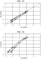
- the present inventors calculated, by simulation, the angular velocity ⁇ Z and the angular velocity G Z detected when the automatic vehicle 5 turns right, and derived the relationship between the angular velocity ⁇ Z and the angular velocity G Z exceeding a predetermined threshold value in a case in which the sensor element 12Z is normal and the sensor element 11Z is normal and in a case in which the sensor element 12Z is normal and the sensor element 11Z fails.
- FIG. 13 shows the relationship between the angular velocity ⁇ Z and the angular velocity G Z obtained by the simulation. In FIG.
- the circles indicate a relationship between the angular velocity ⁇ Z and the angular velocity G Z when the sensor element 11Z is normal, and the triangles indicate a relationship between the angular velocity ⁇ Z and the angular velocity G Z when the sensor element 11Z fails.
- the angular velocity ⁇ Z and the angular velocity G Z substantially coincide with each other. Therefore, a slope of an approximate straight line indicating the relationship between the angular velocity ⁇ Z and the angular velocity G Z , that is, a ratio of the angular velocity ⁇ Z to the angular velocity G Z is approximately 1.
- the ratio of the angular velocity ⁇ Z to the angular velocity G Z is not substantially 1.
- the failure diagnosis circuit 100 may determine whether the ratio of the angular velocity ⁇ Z to the angular velocity G Z satisfies the first standard with a predetermined range including 1 as the first standard.
- step S12 when the comparison result in step S11 does not satisfy the first standard, the failure diagnosis circuit 100 performs failure diagnosis of the sensor element 11Z using the first angular velocity data G1Z or the second angular velocity data G2Z and the acceleration data A3Y in the second diagnosis step S20.
- the failure diagnosis circuit 100 calculates a ratio of the acceleration A Y included in the acceleration data A3Y to the angular velocity ⁇ Z or the angular velocity G Z . Then, in step S22, the failure diagnosis circuit 100 performs the failure diagnosis of the sensor element 11Z based on whether the ratio of the acceleration A Y to the angular velocity ⁇ Z or the angular velocity G Z calculated in step S21 satisfies the second standard. In order to reduce the influence of noise or the like, the failure diagnosis circuit 100 may calculate an average value of the ratios of the acceleration A Y to the angular velocity ⁇ Z or the angular velocity Gz in a predetermined period.
- the failure diagnosis circuit 100 may diagnose that the sensor element 11Z is normal when the ratio of the acceleration A Y to the angular velocity ⁇ Z satisfies the second standard, and may diagnose that the sensor element 11Z fails when the ratio of the acceleration A Y to the angular velocity ⁇ Z does not satisfy the second standard.
- the failure diagnosis circuit 100 may diagnose that the sensor element 11Z fails because the sensor element 12Z is normal, and when the ratio of the acceleration A Y to the angular velocity G Z does not satisfy the second standard, the failure diagnosis circuit 100 may diagnose that the sensor element 11Z is normal because the sensor element 12Z fails.
- the present inventors calculated, by simulation, the acceleration A Y and the angular velocity ⁇ Z detected when the automatic vehicle 5 turns right, and derived the relationship between the acceleration A Y and the angular velocity ⁇ Z exceeding a predetermined threshold value in a case in which the sensor element 13Y is normal and the sensor element 11Z is normal and in a case in which the sensor element 13Y is normal and the sensor element 11Z fails.
- FIG. 14 shows the relationship between the acceleration A Y and the angular velocity ⁇ Z obtained by the simulation. In FIG. 14 , circles indicate the relationship between the acceleration A Y and the angular velocity ⁇ Z when the sensor element 11Z is normal, and triangles indicate the relationship between the acceleration A Y and the angular velocity ⁇ Z when the sensor element 11Z fails.
- the failure diagnosis circuit 100 may diagnose the failure of the sensor element 11Z based on whether a ratio of the acceleration A Y to the angular velocity ⁇ Z satisfies a second standard, using, for example, a value of the ratio of the acceleration A Y to the angular velocity ⁇ Z assumed when both the sensor element 11Z and the sensor element 13Y are normal as a reference value, and using a predetermined range including the reference value as the second standard.
- the failure diagnosis circuit 100 may diagnose the failure of the sensor element 11Z based on whether a ratio of the acceleration A Y to the angular velocity G Z satisfies a second standard, using a value of the ratio of the acceleration A Y to the angular velocity G Z assumed when both the sensor element 12Z and the sensor element 13Y are normal as a reference value and using a predetermined range including the reference value as the second standard.
- the failure diagnosis circuit 100 diagnoses that the sensor element 12Z is normal when the sensor element 11Z fails, and diagnoses that the sensor element 12Z fails when the sensor element 11Z is normal.
- the failure diagnosis circuit 100 repeats the processing in steps S11, S12, S13, S21, and S22 until the failure diagnosis is ended in step S30 shown in FIG. 2 .
- the control circuit 102 transmits the diagnosis result obtained by the failure diagnosis circuit 100 to the processing device 30 via the interface circuit 101.
- the processing device 30 stores the diagnosis result in a built-in memory (not shown).
- the diagnosis result indicates that the sensor element 11Z fails, the processing device 30 may not perform various operations on the detection data SD1Z, or may perform operations for calculating the posture, speed, angle, and the like of the sensor module 1 using the detection data SD2Z instead of the detection data SD1Z.
- the host device 3 may read the diagnosis result from the processing device 30, and when the diagnosis result indicates that the sensor element 11Z fails, the host device 3 may notify a user that the sensor element 11Z is required to be replaced.
- the failure diagnosis device 2 can diagnose whether the sensor element 11Z and the sensor element 12Z are normal or whether the sensor element 11Z or the sensor element 12Z fails in the first diagnosis step S10 on the premise that two or more of the sensor element 11Z, the sensor element 12Z, and the sensor element 13Y are unlikely to simultaneously fail.
- the failure diagnosis device 2 diagnoses that the sensor element 11Z or the sensor element 12Z fails in the first diagnosis step S10, the sensor element 13Y is normal based on the above premise. Therefore, the failure diagnosis device 2 can diagnose, using the first angular velocity data G1Z or the second angular velocity data G2Z and the acceleration data A3Y in the second diagnosis step S20, whether the sensor element 11Z fails. Then, when the failure diagnosis device 2 diagnoses that the sensor element 11Z is normal in the second diagnosis step S20, the sensor element 12Z fails, and when the failure diagnosis device 2 diagnoses that the sensor element 11Z fails, the sensor element 12Z is normal.
- both the sensor element 11Z and the sensor element 12Z detect the angular velocity around the Z axis, and therefore, the difference between the first angular velocity data G1Z and the second angular velocity data G2Z is small, and the failure diagnosis device 2 can easily and accurately diagnose whether the sensor element 11Z and the sensor element 12Z are normal or the sensor element 11Z or the sensor element 12Z fails in the first diagnosis step S10. Then, when diagnosing that the sensor element 11Z and the sensor element 12Z are normal in the first diagnosis step S10, the failure diagnosis device 2 does not need to perform the second diagnosis step S20.
- the failure diagnosis device 2 can efficiently diagnose which of the sensor element 11Z and the sensor element 12Z for detecting the angular velocity around the Z axis fails.
- the failure diagnosis method in the first embodiment whether the sensor element 11Z is normal or fails can be diagnosed. Therefore, for example, when the sensor element 11Z is normal, the sensor module 1 or the host device 3 can perform a required operation with high accuracy using the detection signal SS1Z output from the sensor element 11Z with high detection accuracy, and when the sensor element 11Z fails, the required operation can be continued using the detection signal SS2Z output from the sensor element 12Z.
- the host device 3 can perform fault tolerant design that contributes to the robustness of the system, such as fail-safe that stops an automatic drive control of the automatic vehicle 5 or fail-soft that estimates a position of the automatic vehicle 5 using the angular velocity around the Z axis detected by the 6Dof sensor 20 instead of the angular velocity around the Z axis detected by the angular velocity sensor 10.
- fault tolerant design that contributes to the robustness of the system, such as fail-safe that stops an automatic drive control of the automatic vehicle 5 or fail-soft that estimates a position of the automatic vehicle 5 using the angular velocity around the Z axis detected by the 6Dof sensor 20 instead of the angular velocity around the Z axis detected by the angular velocity sensor 10.
- the sensor module 1 includes the 6Dof sensor 20 that detects a three-axis angular velocity and a three-axis acceleration required for calculating the position or the posture of the automatic vehicle 5, and the angular velocity sensor 10 with high detection accuracy required for calculating a yaw angle ⁇ particularly important for traveling control with high accuracy. That is, both the angular velocity sensor 10 and the 6Dof sensor 20 are not dedicated sensors for failure diagnosis, and according to the failure diagnosis method in the first embodiment, a sensor that is originally required can also be used for failure diagnosis. Therefore, cost reduction is easily implemented.
- a configuration example of a system for implementing the failure diagnosis method according to the second embodiment is the same as that of FIG. 1 , and therefore, illustration and description thereof will be omitted.
- the flowchart showing the overall procedure of the failure diagnosis method according to the second embodiment is the same as FIG. 2 , and therefore, illustration and description thereof will be omitted.
- the procedure of the second diagnosis step S20 shown in FIG. 2 is different from that of the first embodiment.
- FIG. 15 is a flowchart showing an example of a procedure of the second diagnosis step S20 shown in FIG. 2 in the second embodiment.
- the failure diagnosis device 2 acquires a speed in a third-axis direction intersecting the first axis and the second axis.
- the first axis, the second axis, and the third axis may be perpendicular to one another.
- the meaning of "the first axis, the second axis, and the third axis are perpendicularto one another" includes not only a case in which an angle formed by the first axis and the second axis, an angle formed by the second axis and the third axis, and an angle formed by the third axis and the first axis are all strictly 90°, but also a case in which the angle formed by the first axis and the second axis, the angle formed by the second axis and the third axis, and the angle formed by the third axis and the first axis have an error with respect to 90° due to a manufacturing error of the sensor module 1.
- the first axis may be an axis perpendicular to a placement surface of the sensor module 1
- the second axis and the third axis may be axes parallel to the placement surface of the sensor module 1.
- the failure diagnosis device 2 may acquire the speed in the third-axis direction from a device such as a wheel speed sensor or a GNSS Doppler.
- GNSS is an abbreviation for Global Navigation Satellite System.
- the sensor module 1 may include a speed sensor that detects the speed in the third-axis direction, and the failure diagnosis device 2 may acquire the speed in the third-axis direction detected by the speed sensor from the sensor module 1.
- the sensor module 1 may include an acceleration sensor that detects an acceleration in the third-axis direction, and the failure diagnosis device 2 may acquire the acceleration in the third-axis direction detected by the acceleration sensor from the sensor module 1 and integrate the acceleration in the third-axis direction to calculate the speed in the third-axis direction.
- step S122 the failure diagnosis device 2 calculates, using the first angular velocity or the second angular velocity and the speed in the third-axis direction acquired in step S121, centripetal acceleration in the second-axis direction when the angular velocity around the second axis and the angular velocity around the third axis are zero.
- the failure diagnosis device 2 may calculate the centripetal acceleration in the second-axis direction using the first angular velocity and the speed in the third-axis direction, or may calculate the centripetal acceleration in the second-axis direction using the second angular velocity and the speed in the third-axis direction.
- step S123 the failure diagnosis device 2 compares the acceleration in the second-axis direction included in the acceleration signal based on the third detection signal output from the third sensor element 13 with the centripetal acceleration in the second-axis direction calculated in step S122, and performs the failure diagnosis of the first sensor element 11 based on whether a comparison result satisfies the second standard.
- the failure diagnosis device 2 may diagnose that the first sensor element 11 is normal when the comparison result between the acceleration in the second-axis direction and the centripetal acceleration in the second-axis direction satisfies the second standard, and may diagnose that the first sensor element 11 fails when the comparison result between the acceleration in the second-axis direction and the centripetal acceleration in the second-axis direction does not satisfy the second standard.
- the failure diagnosis device 2 may diagnose that the first sensor element 11 fails when the comparison result between the acceleration in the second-axis direction and the centripetal acceleration in the second-axis direction satisfies the second standard, and may diagnose that the first sensor element 11 is normal when the comparison result between the acceleration in the second-axis direction and the centripetal acceleration in the second-axis direction does not satisfy the second standard.
- the second standard when the failure diagnosis device 2 calculates a difference between the acceleration in the second-axis direction and the centripetal acceleration in the second-axis direction in step S123, the second standard may be a predetermined range including 0.
- the failure diagnosis device 2 when the failure diagnosis device 2 calculates a ratio of the acceleration in the second-axis direction to the centripetal acceleration in the second-axis direction in step S123, the second standard may be a predetermined range including 1.
- the failure diagnosis device 2 diagnoses that the second sensor element 12 is normal when the first sensor element 11 fails, and diagnoses that the second sensor element 12 fails when the first sensor element 11 is normal.
- the failure diagnosis method according to the second embodiment will be described in detail with reference to the configuration example shown in FIG. 4 in the first embodiment.
- the configuration and function of the sensor module 1 are the same as those of the first embodiment, and the description thereof is omitted.
- the functions of the interface circuit 101, the control circuit 102, the low-pass filter 103, and the gravitational acceleration separation circuit 104 are the same as those in the first embodiment, and the description thereof is omitted.
- the failure diagnosis circuit 100 performs the failure diagnosis of the sensor element 11Z according to the procedures shown in FIGS. 2 and 15 .
- the sensor elements 11Z, 12Z, and 13Y correspond to the first sensor element 11, the second sensor element 12, and the third sensor element 13 shown in FIG. 1 , respectively
- the detection signals SS1Z, SS2Z, and SS3Y correspond to the first detection signal, the second detection signal, and the third detection signal shown in FIG. 2 , respectively.
- the first angular velocity data G1Z, the second angular velocity data G2Z, and the acceleration data A3Y correspond to the first angular velocity signal, the second angular velocity signal, and the acceleration signal shown in FIG.
- the angular velocity ⁇ Z around the Z axis included in the first angular velocity data G1Z, the angular velocity G Z around the Z axis included in the second angular velocity data G2Z, and the acceleration A Y in the Y-axis direction included in the acceleration data A3Y correspond to the first angular velocity, the second angular velocity, and the acceleration in the second-axis direction shown in FIGS. 2 and 15 , respectively.
- the failure diagnosis circuit 100 sequentially performs step S11, step S12, and step S13 in FIG. 2 .
- step S12 when the comparison result in step S11 does not satisfy the first standard, the failure diagnosis circuit 100 performs failure diagnosis of the sensor element 11Z using the acceleration data A3Y in the second diagnosis step S20.
- the failure diagnosis circuit 100 acquires a speed Vx in the X-axis direction.
- the failure diagnosis device 2 may acquire the speed Vx in the X-axis direction from a device such as a wheel speed sensor or a GNSS Doppler.
- the sensor module 1 may include a speed sensor that detects the speed Vx in the X-axis direction, and the failure diagnosis circuit 100 may acquire the speed Vx in the X-axis direction detected by the speed sensor from the sensor module 1.
- control circuit 102 may acquire the detection data SD2X including an acceleration Ax in the X-axis direction from the sensor module 1 via the interface circuit 101 and output the detection data SD2X to the failure diagnosis circuit 100, and the failure diagnosis circuit 100 may integrate the acceleration Ax in the X-axis direction included in the detection data SD2X to calculate the speed Vx in the X-axis direction.
- step S122 the failure diagnosis circuit 100 calculates, using the angular velocity ⁇ Z or the angular velocity Gz and the speed Vx in the X-axis direction acquired in step S121, a centripetal acceleration in the Y-axis direction when the angular velocity ⁇ Y around the Y axis and the angular velocity ⁇ X around the X axis are zero.
- the failure diagnosis circuit 100 calculates centripetal acceleration V X ⁇ Z in the Y-axis direction corresponding to the Y-axis component of the centripetal acceleration vector a cen shown in the above Formula (11) using the angular velocity ⁇ Z and the speed V X .
- the failure diagnosis circuit 100 calculates the centripetal acceleration V X G Z in the Y-axis direction using the angular velocity Gz and the speed V X .
- step S123 the failure diagnosis circuit 100 compares the acceleration A Y in the Y-axis direction included in the acceleration data A3Y with the centripetal acceleration in the Y-axis direction calculated in step S122, and performs the failure diagnosis of the sensor element 11Z by determining whether the comparison result satisfies the second standard.
- the failure diagnosis circuit 100 may diagnose that the sensor element 11Z is normal when the comparison result between the acceleration A Y and the centripetal acceleration V X ⁇ Z satisfies the second standard, and may diagnose that the sensor element 11Z fails when the comparison result between the acceleration A Y and the centripetal acceleration V X ⁇ Z does not satisfy the second standard.
- the failure diagnosis circuit 100 may diagnose that the sensor element 11Z fails when the comparison result between the acceleration A Y and the centripetal acceleration V X G Z satisfies the second standard, and may diagnose that the sensor element 11Z is normal when the comparison result between the acceleration A Y and the centripetal acceleration V X G Z does not satisfy the second standard.
- the present inventors calculated, by simulation, the acceleration A Y and the centripetal acceleration V X ⁇ Z detected when the automatic vehicle 5 turns right, and derived a relationship between the acceleration A Y and the centripetal acceleration V X ⁇ Z exceeding a predetermined threshold value in a case in which the sensor element 13Y is normal and the sensor element 11Z is normal and in a case in which the sensor element 13Y is normal and the sensor element 11Z fails.
- FIG. 16 shows the relationship between the acceleration A Y and the centripetal acceleration V X ⁇ Z obtained by the simulation. In FIG.
- the circles indicate the relationship between the acceleration A Y and the centripetal acceleration V X ⁇ Z when the sensor element 11Z is normal, and the triangles indicate the relationship between the acceleration A Y and the centripetal acceleration V X ⁇ Z when the sensor element 11Z fails.
- the acceleration A Y and the centripetal acceleration V X ⁇ Z substantially coincide with each other. Therefore, a slope of an approximate straight line indicating the relationship between the acceleration A Y and the centripetal acceleration V X ⁇ Z , that is, a ratio of the acceleration A Y to the centripetal acceleration V X ⁇ Z is approximately 1.
- the ratio of the acceleration A Y to the centripetal acceleration V X ⁇ Z is not substantially 1.
- the failure diagnosis circuit 100 may diagnose the failure of the sensor element 11Z based on whether the ratio of the acceleration A Y to the centripetal acceleration V X ⁇ Z satisfies the second standard with a predetermined range including 1 as the second standard.
- the failure diagnosis circuit 100 may diagnose the failure of the sensor element 11Z based on whether a ratio of the acceleration A Y to the centripetal acceleration VxGz satisfies the second standard with a predetermined range including 1 as the second standard.
- step S123 the failure diagnosis circuit 100 diagnoses that the sensor element 12Z is normal when the sensor element 11Z fails, and diagnoses that the sensor element 12Z fails when the sensor element 11Z is normal.
- the failure diagnosis circuit 100 repeats the processing in steps S11, S12, S13, S121, S122, and S123 until the failure diagnosis is ended in step S30 shown in FIG. 2 .
- a configuration example of a system for implementing the failure diagnosis method according to the third embodiment is the same as that of FIG. 1 , and therefore, illustration and description thereof will be omitted.
- the flowchart showing the overall procedure of the failure diagnosis method according to the third embodiment is the same as FIG. 2 , and therefore, illustration and description thereof will be omitted.
- the procedure of the second diagnosis step S20 shown in FIG. 2 is different from that of the first embodiment.
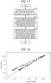
- FIG. 17 is a flowchart showing an example of the procedure of the second diagnosis step S20 shown in FIG. 2 in the third embodiment.
- the failure diagnosis device 2 acquires a position in the second-axis direction with a rotation center of a rotational motion around the first axis performed by the sensor module 1 as an origin.
- the position in the second-axis direction can also be said to be a distance from the rotation center to the sensor module 1.
- the failure diagnosis device 2 can acquire the position in the second-axis direction by map matching or the like using position information or map data obtained from the GNSS and an external sensor such as a LiDAR or a camera.
- LiDAR is an abbreviation for Light Detection And Ranging.
- the failure diagnosis device 2 can also calculate the position in the second-axis direction using the left and right wheel speeds obtained from the wheel speed sensors.
- step S222 the failure diagnosis device 2 calculates, using the first angular velocity or the second angular velocity and the position in the second-axis direction acquired in step S221, a centripetal acceleration in the second-axis direction when the angular velocity around the second axis and the angular velocity around the third axis intersecting the first axis and the second axis are zero.
- the first axis, the second axis, and the third axis may be perpendicular to one another.
- the meaning of "the first axis, the second axis, and the third axis are perpendicular to one another" includes not only a case in which an angle formed by the first axis and the second axis, an angle formed by the second axis and the third axis, and an angle formed by the third axis and the first axis are all strictly 90°, but also a case in which the angle formed by the first axis and the second axis, the angle formed by the second axis and the third axis, and the angle formed by the third axis and the first axis have an error with respect to 90° due to a manufacturing error of the sensor module 1.
- the first axis may be an axis perpendicular to a placement surface of the sensor module 1
- the second axis and the third axis may be axes parallel to the placement surface of the sensor module 1.
- the failure diagnosis device 2 may calculate the centripetal acceleration in the second-axis direction using the first angular velocity and the position in the second-axis direction, or may calculate the centripetal acceleration in the second-axis direction using the second angular velocity and the position in the second-axis direction.
- the failure diagnosis device 2 compares the acceleration in the second-axis direction included in the acceleration signal based on the third detection signal output from the third sensor element 13 with the centripetal acceleration in the second-axis direction calculated in step S222, and performs the failure diagnosis of the first sensor element 11 based on whether a comparison result satisfies the second standard.
- the failure diagnosis device 2 may diagnose that the first sensor element 11 is normal when the comparison result between the acceleration in the second-axis direction and the centripetal acceleration in the second-axis direction satisfies the second standard, and may diagnose that the first sensor element 11 fails when the comparison result between the acceleration in the second-axis direction and the centripetal acceleration in the second-axis direction does not satisfy the second standard.
- the failure diagnosis device 2 may diagnose that the first sensor element 11 fails when the comparison result between the acceleration in the second-axis direction and the centripetal acceleration in the second-axis direction satisfies the second standard, and may diagnose that the first sensor element 11 is normal when the comparison result between the acceleration in the second-axis direction and the centripetal acceleration in the second-axis direction does not satisfy the second standard.
- the second standard may be a predetermined range including 0.
- the second standard may be a predetermined range including 1.
- the failure diagnosis device 2 diagnoses that the second sensor element 12 is normal when the first sensor element 11 fails, and diagnoses that the second sensor element 12 fails when the first sensor element 11 is normal.
- the failure diagnosis method according to the third embodiment will be described in detail with reference to the configuration example shown in FIG. 4 in the first embodiment.
- the configuration and function of the sensor module 1 are the same as those of the first embodiment, and the description thereof is omitted.
- the functions of the interface circuit 101, the control circuit 102, the low-pass filter 103, and the gravitational acceleration separation circuit 104 are the same as those in the first embodiment, and the description thereof is omitted.
- the failure diagnosis circuit 100 performs failure diagnosis of the sensor element 11Z according to the procedures shown in FIGS. 2 and 17 .
- the sensor elements 11Z, 12Z, and 13Y correspond to the first sensor element 11, the second sensor element 12, and the third sensor element 13 shown in FIG. 1 , respectively
- the detection signals SS1Z, SS2Z, and SS3Y correspond to the first detection signal, the second detection signal, and the third detection signal shown in FIG. 2 , respectively.
- the first angular velocity data G1Z, the second angular velocity data G2Z, and the acceleration data A3Y correspond to the first angular velocity signal, the second angular velocity signal, and the acceleration signal shown in FIG.
- the angular velocity ⁇ Z around the Z axis included in the first angular velocity data G1Z, the angular velocity G Z around the Z axis included in the second angular velocity data G2Z, and the acceleration A Y in the Y-axis direction included in the acceleration data A3Y correspond to the first angular velocity, the second angular velocity, and the acceleration in the second-axis direction shown in FIGS. 2 and 17 , respectively.
- the failure diagnosis circuit 100 sequentially performs step S11, step S12, and step S13 in FIG. 2 .
- step S12 when the comparison result in step S11 does not satisfy the first standard, the failure diagnosis circuit 100 performs failure diagnosis of the sensor element 11Z using the acceleration data A3Y in the second diagnosis step S20.
- the failure diagnosis circuit 100 acquires a position r Y in the Y-axis direction.
- the failure diagnosis circuit 100 can acquire the position r Y in the Y-axis direction by map matching or the like using position information or map data obtained from the GNSS and an external sensor such as a LiDAR or a camera.
- the failure diagnosis circuit 100 can also calculate the position r Y in the Y-axis direction using the left and right wheel speeds obtained from the wheel speed sensors.
- step S222 the failure diagnosis circuit 100 calculates, using the angular velocity ⁇ Z or the angular velocity G Z and the position r Y in the Y-axis direction acquired in step S221, a centripetal acceleration in the Y-axis direction when the angular velocity ⁇ Y around the Y axis and the angular velocity ⁇ X around the X axis are zero.
- the failure diagnosis circuit 100 calculates the centripetal acceleration -r Y ⁇ Z 2 in the Y-axis direction corresponding to the Y-axis component of the centripetal acceleration vector a cen shown in the above Formula (11) using the angular velocity ⁇ Z and the position r Y .
- the failure diagnosis circuit 100 calculates the centripetal acceleration -r Y G Z 2 in the Y-axis direction using the angular velocity G Z and the position r Y .
- step S223 the failure diagnosis circuit 100 compares the acceleration A Y in the Y-axis direction included in the acceleration data A3Y with the centripetal acceleration in the Y-axis direction calculated in step S222, and performs the failure diagnosis of the sensor element 11Z by determining whether the comparison result satisfies the second standard.
- the failure diagnosis device 2 may diagnose that the sensor element 11Z is normal when the comparison result between the acceleration A Y and the centripetal acceleration V X ⁇ Z satisfies the second standard, and may diagnose that the sensor element 11Z fails when the comparison result between the acceleration A Y and the centripetal acceleration V X ⁇ Z does not satisfy the second standard.
- the failure diagnosis circuit 100 may diagnose that the sensor element 11Z fails when the comparison result between the acceleration A Y and the centripetal acceleration V X G Z satisfies the second standard, and may diagnose that the sensor element 11Z is normal when the comparison result between the acceleration A Y and the centripetal acceleration V X G Z does not satisfy the second standard.
- the present inventors calculated, by simulation, the acceleration A Y and the centripetal acceleration -r Y ⁇ Z 2 detected when the automatic vehicle 5 turns right, and derived the relationship between the acceleration A Y and the centripetal acceleration -r Y ⁇ Z 2 exceeding a predetermined threshold value in a case in which the sensor element 13Y is normal and the sensor element 11Z is normal and in a case in which the sensor element 13Y is normal and the sensor element 11Z fails.
- FIG. 18 shows the relationship between the acceleration A Y and the centripetal acceleration -r Y ⁇ Z 2 obtained by the simulation. In FIG.
- circles indicate the relationship between the acceleration A Y and the centripetal acceleration -r Y ⁇ Z 2 when the sensor element 11Z is normal, and triangles indicate the relationship between the acceleration Ay and the centripetal acceleration -r Y ⁇ Z 2 when the sensor element 11Z fails.
- a slope of an approximate straight line indicating the relationship between the acceleration A Y and the centripetal acceleration -r Y ⁇ Z 2 that is, a ratio of the acceleration A Y to the centripetal acceleration -r Y ⁇ Z 2 is approximately 1.
- the ratio of the acceleration A Y to the centripetal acceleration -r Y ⁇ Z 2 is not substantially 1.
- the failure diagnosis circuit 100 may diagnose the failure of the sensor element 11Z based on whether the ratio of the acceleration A Y to the centripetal acceleration -r Y ⁇ Z 2 satisfies the second standard with a predetermined range including 1 as the second standard.
- the failure diagnosis circuit 100 may diagnose the failure of the sensor element 11Z based on whether the ratio of the acceleration A Y to the centripetal acceleration -r Y G Z 2 satisfies the second standard with a predetermined range including 1 as the second standard.
- the failure diagnosis circuit 100 diagnoses that the sensor element 12Z is normal when the sensor element 11Z fails, and diagnoses that the sensor element 12Z fails when the sensor element 11Z is normal.
- the failure diagnosis circuit 100 repeats the processing in steps S11, S12, S13, S221, S222, and S223 until the failure diagnosis is ended in step S30 shown in FIG. 2 .
- a configuration example of a system for implementing the failure diagnosis method according to the fourth embodiment is the same as that of FIG. 1 , and therefore, illustration and description thereof will be omitted.
- the flowchart showing the overall procedure of the failure diagnosis method according to the fourth embodiment is the same as FIG. 2 , and therefore, illustration and description thereof will be omitted.
- the procedure of the second diagnosis step S20 shown in FIG. 2 is different from that of the first embodiment.
- FIG. 19 is a flowchart showing an example of the procedure of the second diagnosis step S20 shown in FIG. 2 in the fourth embodiment.
- step S321 the failure diagnosis device 2 acquires a position in a third-axis direction intersecting the first axis and the second axis with a rotation center of a rotational motion around the first axis performed by the sensor module 1 as an origin.
- the first axis, the second axis, and the third axis may be perpendicular to one another.
- the meaning of "the first axis, the second axis, and the third axis are perpendicular to one another" includes not only a case in which an angle formed by the first axis and the second axis, an angle formed by the second axis and the third axis, and an angle formed by the third axis and the first axis are all strictly 90°, but also a case in which the angle formed by the first axis and the second axis, the angle formed by the second axis and the third axis, and the angle formed by the third axis and the first axis have an error with respect to 90° due to a manufacturing error of the sensor module 1.
- the first axis may be an axis perpendicular to a placement surface of the sensor module 1
- the second axis and the third axis may be axes parallel to the placement surface of the sensor module 1.
- the position in the third-axis direction can also be said to be a distance from the rotation center to the sensor module 1.
- the failure diagnosis device 2 can acquire the position in the third-axis direction by map matching or the like using position information or map data obtained from the GNSS and an external sensor such as a LiDAR or a camera.
- the failure diagnosis device 2 can also calculate the position in the third-axis direction using the left and right wheel speeds obtained from the wheel speed sensors.
- step S322 the failure diagnosis device 2 calculates, using the first angular velocity or the second angular velocity and the position in the third-axis direction acquired in step S321, the Euler acceleration in the second-axis direction when the angular velocity around the second axis and the angular velocity around the third axis are zero.
- the failure diagnosis device 2 may calculate the Euler acceleration in the second-axis direction using the first angular velocity and the position in the third-axis direction, or may calculate the Euler acceleration in the second-axis direction using the second angular velocity and the position in the third-axis direction.
- step S323 the failure diagnosis device 2 compares the acceleration in the second-axis direction included in the acceleration signal based on the third detection signal output from the third sensor element 13 with the Euler acceleration in the second-axis direction calculated in step S322, and performs the failure diagnosis of the first sensor element 11 based on whether the comparison result satisfies the second standard.
- the failure diagnosis device 2 may diagnose that the first sensor element 11 is normal when the comparison result between the acceleration in the second-axis direction and the Euler acceleration in the second-axis direction satisfies the second standard, and may diagnose that the first sensor element 11 fails when the comparison result between the acceleration in the second-axis direction and the Euler acceleration in the second-axis direction does not satisfy the second standard.
- the failure diagnosis device 2 may diagnose that the first sensor element 11 fails when the comparison result between the acceleration in the second-axis direction and the Euler acceleration in the second-axis direction satisfies the second standard, and may diagnose that the first sensor element 11 is normal when the comparison result between the acceleration in the second-axis direction and the Euler acceleration in the second-axis direction does not satisfy the second standard.
- the second standard may be a predetermined range including 0.
- the second standard may be a predetermined range including 1.
- the failure diagnosis device 2 diagnoses that the second sensor element 12 is normal when the first sensor element 11 fails, and diagnoses that the second sensor element 12 fails when the first sensor element 11 is normal.
- the failure diagnosis method according to the fourth embodiment will be described in detail with reference to the configuration example shown in FIG. 4 in the first embodiment.
- the configuration and function of the sensor module 1 are the same as those of the first embodiment, and the description thereof is omitted.
- the function of the interface circuit 101 is the same as that of the first embodiment, and the description thereof is omitted.
- control circuit 102 acquires the detection data SD1Z, SD2Z, SD3X and the pitch angle ⁇ from the processing device 30 via the interface circuit 101 in a period in which the automatic vehicle 5 performs a rotational motion for turning right or left.
- the low-pass filter 103 acquires the detection data SD1Z, SD2Z, and SD3X from the control circuit 102, and performs low-pass filter processing to reduce high-frequency noise components.
- the low-pass filtered detection data SD1Z is input to the failure diagnosis circuit 100 as first angular velocity data G1Z.
- the first angular velocity data G1Z includes the angular velocity ⁇ Z based on the angular velocity around the Z axis detected by the sensor element 11Z.
- the low-pass filtered detection data SD2Z is input to the failure diagnosis circuit 100 as second angular velocity data G2Z.
- the second angular velocity data G2Z includes the angular velocity G Z based on the angular velocity around the Z axis detected by the sensor element 12Z.
- the gravitational acceleration separation circuit 104 separates a gravitational acceleration component from the low-pass filtered detection data SD3X. Specifically, the gravitational acceleration separation circuit 104 calculates -gsin ⁇ , which is a gravitational acceleration component in the X-axis direction of the gravitational acceleration vector a g , by using the pitch angle ⁇ , and subtracts -gsin ⁇ from the acceleration in the X-axis direction included in the low-pass filtered detection data SD3X.
- the detection data SD3X from which the gravitational acceleration component is separated by the gravitational acceleration separation circuit 104 is input to the failure diagnosis circuit 100 as the acceleration data A3X.
- the acceleration data A3X includes the acceleration Ax based on the acceleration in the X-axis direction detected by the sensor element 13X.
- the failure diagnosis circuit 100 performs failure diagnosis of the sensor element 11Z using the first angular velocity data G1Z, the second angular velocity data G2Z, and the acceleration data A3X. Specifically, the failure diagnosis circuit 100 performs the failure diagnosis of the sensor element 11Z according to the procedures shown in FIGS. 2 and 19 .
- the sensor elements 11Z, 12Z, and 13X correspond to the first sensor element 11, the second sensor element 12, and the third sensor element 13 shown in FIG. 1 , respectively
- the detection signals SS1Z, SS2Z, and SS3X correspond to the first detection signal, the second detection signal, and the third detection signal shown in FIG. 2 , respectively.
- the first angular velocity data G1Z, the second angular velocity data G2Z, and the acceleration data A3X correspond to the first angular velocity signal, the second angular velocity signal, and the acceleration signal shown in FIG. 2 , respectively, and the Z axis, the X axis, and the Y axis correspond to the first axis, the second axis, and the third axis shown in FIGS. 2 and 19 , respectively.
- the angular velocity ⁇ Z around the Z axis included in the first angular velocity data G1Z, the angular velocity G Z around the Z axis included in the second angular velocity data G2Z, and the acceleration A X in the X-axis direction included in the acceleration data A3X correspond to the first angular velocity, the second angular velocity, and the acceleration in the second-axis direction shown in FIGS. 2 and 19 , respectively.
- the failure diagnosis circuit 100 sequentially performs step S11, step S12, and step S13 in FIG. 2 .
- step S12 when the comparison result in step S11 does not satisfy the first standard, the failure diagnosis circuit 100 performs failure diagnosis of the sensor element 11Z using the acceleration data A3X in the second diagnosis step S20.
- the failure diagnosis circuit 100 acquires a position r Y in the Y-axis direction.
- the failure diagnosis circuit 100 can acquire the position r Y in the Y-axis direction by map matching or the like using position information or map data obtained from the GNSS and an external sensor such as a LiDAR or a camera.
- the failure diagnosis circuit 100 can also calculate the position r Y in the Y-axis direction using the left and right wheel speeds obtained from the wheel speed sensors.
- step S322 the failure diagnosis circuit 100 calculates, using the angular velocity ⁇ Z or the angular velocity G Z and the position r Y in the Y-axis direction acquired in step S321, the Euler acceleration in the X-axis direction when the angular velocity ⁇ X around the X-axis and the angular velocity ⁇ Y around the Y-axis are zero. Specifically, the failure diagnosis circuit 100 calculates the Euler acceleration -r Y ⁇ Z ' in the X-axis direction corresponding to the X-axis component of the Euler acceleration vector a eul shown in the above Formula (12) using the angular velocity ⁇ Z and the position r Y .
- ⁇ Z ' represents a differential of ⁇ Z .
- the failure diagnosis circuit 100 calculates the Euler acceleration -r Y G Z ' in the X-axis direction using the angular velocity G Z and the position r Y .
- G Z ' represents a differential of G Z .
- step S323 the failure diagnosis circuit 100 compares the acceleration Ax in the X-axis direction included in the acceleration data A3X with the Euler acceleration in the X-axis direction calculated in step S322, and performs the failure diagnosis of the sensor element 11Z based on whether the comparison result satisfies the second standard.
- the failure diagnosis device 2 may diagnose that the sensor element 11Z is normal when the comparison result between the acceleration Ax and the Euler acceleration -r Y ⁇ Z ' satisfies the second standard, and may diagnose that the sensor element 11Z fails when the comparison result between the acceleration Ax and the Euler acceleration -r Y ⁇ Z ' does not satisfy the second standard.
- the failure diagnosis circuit 100 may diagnose that the sensor element 11Z fails when the comparison result between the acceleration A X and the Euler acceleration -r Y G Z ' satisfies the second standard, and may diagnose that the sensor element 11Z is normal when the comparison result between the acceleration A X and the Euler acceleration -r Y G Z ' does not satisfy the second standard.
- the failure diagnosis circuit 100 may diagnose the failure of the sensor element 11Z based on whether a ratio of the acceleration A X to the Euler acceleration -r Y ⁇ Z ' satisfies the second standard with a predetermined range including 1 as the second standard.
- the failure diagnosis circuit 100 may diagnose the failure of the sensor element 11Z based on whether a ratio of the acceleration Ax to the Euler acceleration -r Y G Z ' satisfies the second standard with a predetermined range including 1 as the second standard.
- the failure diagnosis circuit 100 diagnoses that the sensor element 12Z is normal when the sensor element 11Z fails, and diagnoses that the sensor element 12Z fails when the sensor element 11Z is normal.
- the failure diagnosis circuit 100 repeats the processing in steps S11, S12, S13, S321, S322, and S323 until the failure diagnosis is ended in step S30 shown in FIG. 2 .
- a configuration example of a system for implementing the failure diagnosis method according to the fifth embodiment is the same as that of FIG. 1 , and therefore, illustration and description thereof will be omitted.
- the flowchart showing the overall procedure of the failure diagnosis method according to the fifth embodiment is the same as FIG. 2 , and therefore, the illustration and description thereof will be omitted.
- the procedure of the second diagnosis step S20 shown in FIG. 2 is different from that of the first embodiment.
- FIG. 20 is a flowchart showing an example of the procedure of the second diagnosis step S20 shown in FIG. 2 in the fifth embodiment.
- step S421 the failure diagnosis device 2 acquires a position in a third-axis direction intersecting the first axis and the second axis with a rotation center of a rotational motion around the first axis performed by the sensor module 1 as an origin.
- the first axis, the second axis, and the third axis may be perpendicular to one another.
- the meaning of "the first axis, the second axis, and the third axis are perpendicular to one another" includes not only a case in which an angle formed by the first axis and the second axis, an angle formed by the second axis and the third axis, and an angle formed by the third axis and the first axis are all strictly 90°, but also a case in which the angle formed by the first axis and the second axis, the angle formed by the second axis and the third axis, and the angle formed by the third axis and the first axis have an error with respect to 90° due to a manufacturing error of the sensor module 1.
- the first axis may be an axis perpendicular to a placement surface of the sensor module 1
- the second axis and the third axis may be axes parallel to the placement surface of the sensor module 1.
- the position in the third-axis direction can also be said to be a distance from the rotation center to the sensor module 1.
- the failure diagnosis device 2 can acquire the position in the third-axis direction by map matching or the like using position information or map data obtained from the GNSS and an external sensor such as a LiDAR or a camera.
- the failure diagnosis device 2 can also calculate the position in the third-axis direction using the left and right wheel speeds obtained from the wheel speed sensors.
- step S422 the failure diagnosis device 2 calculates, using the first angular velocity or the second angular velocity and the position in the third-axis direction acquired in step S421, the Coriolis acceleration in the second-axis direction when the angular velocity around the second axis and the angular velocity around the third axis are zero.
- the failure diagnosis device 2 may calculate the Coriolis acceleration in the second-axis direction using the first angular velocity and the position in the third-axis direction, or may calculate the Coriolis acceleration in the second-axis direction using the second angular velocity and the position in the third-axis direction.
- step S423 the failure diagnosis device 2 compares the acceleration in the second-axis direction included in the acceleration signal based on the third detection signal output from the third sensor element 13 with the Coriolis acceleration in the second-axis direction calculated in step S422, and performs the failure diagnosis of the first sensor element 11 based on whether the comparison result satisfies the second standard.
- the failure diagnosis device 2 may diagnose that the first sensor element 11 is normal when the comparison result between the acceleration in the second-axis direction and the Coriolis acceleration in the second-axis direction satisfies the second standard, and may diagnose that the first sensor element 11 fails when the comparison result between the acceleration in the second-axis direction and the Coriolis acceleration in the second-axis direction does not satisfy the second standard.
- the failure diagnosis device 2 may diagnose that the first sensor element 11 fails when the comparison result between the acceleration in the second-axis direction and the Coriolis acceleration in the second-axis direction satisfies the second standard, and may diagnose that the first sensor element 11 is normal when the comparison result between the acceleration in the second-axis direction and the Coriolis acceleration in the second-axis direction does not satisfy the second standard.
- the second standard may be a predetermined range including 0.
- the second standard may be a predetermined range including 1.
- step S423 the failure diagnosis device 2 diagnoses that the second sensor element 12 is normal when the first sensor element 11 fails, and diagnoses that the second sensor element 12 fails when the first sensor element 11 is normal.
- the failure diagnosis method according to the fifth embodiment will be described in detail with reference to the configuration example shown in FIG. 4 in the first embodiment.
- the configuration and function of the sensor module 1 are the same as those of the first embodiment, and the description thereof is omitted.
- the functions of the interface circuit 101, the control circuit 102, the low-pass filter 103, and the gravitational acceleration separation circuit 104 are the same as those in the fourth embodiment, and the description thereof is omitted.
- the failure diagnosis circuit 100 performs failure diagnosis of the sensor element 11Z using the first angular velocity data G1Z, the second angular velocity data G2Z, and the acceleration data A3X. Specifically, the failure diagnosis circuit 100 performs the failure diagnosis of the sensor element 11Z according to the procedures shown in FIGS. 2 and 20 .
- the sensor elements 11Z, 12Z, and 13X correspond to the first sensor element 11, the second sensor element 12, and the third sensor element 13 shown in FIG. 1 , respectively
- the detection signals SS1Z, SS2Z, and SS3X correspond to the first detection signal, the second detection signal, and the third detection signal shown in FIG. 2 , respectively.
- the first angular velocity data G1Z, the second angular velocity data G2Z, and the acceleration data A3X correspond to the first angular velocity signal, the second angular velocity signal, and the acceleration signal shown in FIG. 2 , respectively, and the Z axis, the X axis, and the Y axis correspond to the first axis, the second axis, and the third axis shown in FIGS. 2 and 20 , respectively.
- the angular velocity ⁇ Z around the Z axis included in the first angular velocity data G1Z, the angular velocity G Z around the Z axis included in the second angular velocity data G2Z, and the acceleration A X in the X-axis direction included in the acceleration data A3X correspond to the first angular velocity, the second angular velocity, and the acceleration in the second-axis direction shown in FIGS. 2 and 20 , respectively.
- the failure diagnosis circuit 100 sequentially performs step S11, step S12, and step S13 in FIG. 2 .
- step S12 when the comparison result in step S11 does not satisfy the first standard, the failure diagnosis circuit 100 performs failure diagnosis of the sensor element 11Z using the acceleration data A3X in the second diagnosis step S20.
- the failure diagnosis circuit 100 acquires a position r Y in the Y-axis direction.
- the failure diagnosis circuit 100 can acquire the position r Y in the Y-axis direction by map matching or the like using position information or map data obtained from the GNSS and an external sensor such as a LiDAR or a camera.
- the failure diagnosis circuit 100 can also calculate the position r Y in the Y-axis direction using the left and right wheel speeds obtained from the wheel speed sensors.
- step S422 the failure diagnosis circuit 100 calculates, using the angular velocity ⁇ Z or the angular velocity G Z and the position r Y in the Y-axis direction acquired in step S421, the Coriolis acceleration in the X-axis direction when the angular velocity ⁇ X around the X-axis and the angular velocity ⁇ Y around the Y-axis are zero. Specifically, the failure diagnosis circuit 100 calculates Coriolis acceleration -2r Y ' ⁇ Z in the X-axis direction corresponding to the X-axis component of the Coriolis acceleration vector a col shown in the above Formula (13) using the angular velocity ⁇ Z and the position r Y .
- r Y ' represents a differential of ry.
- the failure diagnosis circuit 100 calculates the Coriolis acceleration -2r Y 'G Z in the X-axis direction using the angular velocity G Z and the position r Y .
- step S423 the failure diagnosis circuit 100 compares the acceleration Ax in the X-axis direction included in the acceleration data A3X with the Coriolis acceleration in the X-axis direction calculated in step S422, and performs the failure diagnosis of the sensor element 11Z based on whether the comparison result satisfies the second standard.
- the failure diagnosis device 2 may diagnose that the sensor element 11Z is normal when the comparison result between the acceleration Ax and the Coriolis acceleration -2r Y ' ⁇ Z satisfies the second standard, and may diagnose that the sensor element 11Z fails when the comparison result between the acceleration A X and the Coriolis acceleration -2r Y ' ⁇ Z does not satisfy the second standard.
- the failure diagnosis circuit 100 may diagnose that the sensor element 11Z fails when the comparison result between the acceleration Ax and the Coriolis acceleration -2r Y 'G Z satisfies the second standard, and may diagnose that the sensor element 11Z is normal when the comparison result between the acceleration A X and the Coriolis acceleration -2r Y 'G Z does not satisfy the second standard.
- the failure diagnosis circuit 100 may diagnose the failure of the sensor element 11Z based on whether a ratio of the acceleration A X to the Coriolis acceleration -2r Y ' ⁇ Z satisfies the second standard with a predetermined range including 1 as the second standard.
- the failure diagnosis circuit 100 may diagnose the failure of the sensor element 11Z based on whether a ratio of the acceleration A X to the Coriolis acceleration -2r Y 'G Z satisfies the second standard with a predetermined range including 1 as the second standard.
- step S423 the failure diagnosis circuit 100 diagnoses that the sensor element 12Z is normal when the sensor element 11Z fails, and diagnoses that the sensor element 12Z fails when the sensor element 11Z is normal.
- the failure diagnosis circuit 100 repeats the processing in steps S11, S12, S13, S421, S422, and S423 until the failure diagnosis is ended in step S30 shown in FIG. 2 .
- FIG. 21 is a diagram showing a functional configuration example of a sensor module according to the embodiment.
- a sensor module 200 according to the embodiment includes the first sensor element 11, the second sensor element 12, the third sensor element 13, and the failure diagnosis circuit 100.
- the first sensor element 11 detects an angular velocity around the first axis and outputs a first detection signal SS1.
- the second sensor element 12 detects an angular velocity around the first axis and outputs a second detection signal SS2. That is, both the first sensor element 11 and the second sensor element 12 detect the angular velocity around the first axis, but the first sensor element 11 may have detection accuracy higher than that of the second sensor element 12.
- the third sensor element 13 detects an acceleration in a second-axis direction intersecting the first axis and outputs a third detection signal SS3.
- the first axis and the second axis may be perpendicular to each other.
- the first axis may be an axis perpendicular to a placement surface of the sensor module 1
- the second axis may be an axis parallel to the placement surface of the sensor module 1.
- the failure diagnosis circuit 100 is connected to the sensor module 1 and performs failure diagnosis of the first sensor element 11 by the failure diagnosis method according to any one of the first to fifth embodiments. Specifically, the failure diagnosis circuit 100 compares a first angular velocity with a second angular velocity, and diagnoses that the first sensor element 11 is normal when the comparison result satisfies the first standard.
- the first angular velocity is an angular velocity around the first axis included in a first angular velocity signal G1 based on the first detection signal SS1
- the second angular velocity is an angular velocity around the first axis included in a second angular velocity signal G2 based on the second detection signal SS2.
- the failure diagnosis circuit 100 performs the failure diagnosis of the first sensor element 11 using an acceleration signal A3 based on the third detection signal SS3.
- FIG. 22 is a diagram showing a specific configuration example of the sensor module 200.
- the sensor module 200 includes the angular velocity sensor 10, the 6Dof sensor 20, the processing device 30, and a failure diagnosis device 40.
- the sensor module 200 may have a configuration omitting or changing a part of the components in FIG. 22 , or adding other components to the components in FIG. 22 .
- the angular velocity sensor 10, the 6Dof sensor 20, the processing device 30, and the failure diagnosis device 40 are accommodated in a housing (not shown).
- the configurations and functions of the angular velocity sensor 10, the 6Dof sensor 20, and the processing device 30 are as described with reference to FIG. 4 , and therefore, the description thereof is omitted.
- the failure diagnosis device 40 includes the failure diagnosis circuit 100, the interface circuit 101, the control circuit 102, the low-pass filter 103, and the gravitational acceleration separation circuit 104.
- the functions of the interface circuit 101, the control circuit 102, the low-pass filter 103, and the gravitational acceleration separation circuit 104 are the same as those described with reference to FIG. 4 , and therefore, description thereof will be omitted.
- the failure diagnosis circuit 100 performs failure diagnosis of the sensor element 11Z using the first angular velocity data G1Z, the second angular velocity data G2Z, and the acceleration data A3Y. Specifically, the failure diagnosis circuit 100 compares the angular velocity ⁇ Z around the Z axis included in the first angular velocity data G1Z based on the detection signal SS1Z with the angular velocity G Z around the Z axis included in the second angular velocity data G2Z based on the detection signal SS2Z, and diagnoses that the sensor element 11Z is normal when the comparison result satisfies a first standard.
- the failure diagnosis circuit 100 performs the failure diagnosis of the sensor element 11Z using the acceleration data A3Y based on the detection signal SS3Y.
- the sensor elements 11Z, 12Z, and 13X correspond to the first sensor element 11, the second sensor element 12, and the third sensor element 13 shown in FIG. 21 , respectively
- the detection signals SS1Z, SS2Z, and SS3Y correspond to the first detection signal SS1, the second detection signal SS2, and the third detection signal SS3 shown in FIG. 21 , respectively.
- the first angular velocity data G1Z, the second angular velocity data G2Z, and the acceleration data A3Y correspond to the first angular velocity signal G1, the second angular velocity signal G2, and the acceleration signal A3 shown in FIG. 21 , respectively, and the Z axis, the Y axis, and the X axis correspond to the first axis, the second axis, and the third axis, respectively.
- the angular velocity ⁇ Z around the Z axis included in the first angular velocity data G1Z, the angular velocity G Z around the Z axis included in the second angular velocity data G2Z, and the acceleration A Y in the Y-axis direction included in the acceleration data A3Y correspond to the first angular velocity, the second angular velocity, and the acceleration in the second-axis direction, respectively.
- the failure diagnosis circuit 100 performs failure diagnosis of the sensor element 11Z according to the procedures shown in FIG. 2 and FIG. 3 , FIG. 15 , or FIG. 17 . These procedures are as described above, and therefore, description thereof is omitted.
- sensor module 200 Other configurations and functions of the sensor module 200 are the same as those of the sensor module 1 shown in FIG. 4 , and therefore, description thereof will be omitted.
- the failure diagnosis circuit 100 may also perform the failure diagnosis of the sensor element 11Z using the first angular velocity data G1Z, the second angular velocity data G2Z, and the acceleration data A3X. Specifically, the failure diagnosis circuit 100 may perform the failure diagnosis of the sensor element 11Z according to the procedures shown in FIG. 2 and FIG. 19 or FIG. 20 . These procedures are as described above, and therefore, description thereof is omitted.
- the sensor module 1 may be mounted on a vehicle other than an automatic vehicle.
- vehicle examples include, in addition to an automatic vehicle, an aircraft such as a jet machine or a helicopter, a ship, a rocket, an artificial satellite, and a railway vehicle.
- the specific procedure of the second diagnosis step S20 is not limited to the procedure shown in FIG. 3 , FIG. 15 , FIG. 17 , FIG. 19, or FIG. 20 .
- the failure diagnosis device 2, the failure diagnosis device 40, or the failure diagnosis circuit 100 may perform the failure diagnosis of the sensor element 11Z based on whether a distribution of the angular velocity ⁇ Z or the angular velocity G Z and the acceleration A Y satisfies the second standard with a range of the ellipse shown in FIG. 12 as the second standard.
- the failure diagnosis device 2, the failure diagnosis device 40, or the failure diagnosis circuit 100 may input the angular velocity ⁇ Z or the angular velocity G Z and the acceleration A Y to Kerman filter to perform the failure diagnosis of the sensor element 11Z.
- the sensor module 1 or the sensor module 200 includes the angular velocity sensor 10 and the 6Dof sensor 20, and other sensors may be provided instead of the angular velocity sensor 10 and the 6Dof sensor 20.
- both the sensor module 1 and the sensor module 200 may include two angular velocity sensors for detecting the angular velocity in the Z axis and a three-axis acceleration sensor, or may include two 6Dof sensors.
- the processing device 30 performs an operation of the posture, the speed, the angle, and the like of the sensor module 1, and the host device 3 may perform an operation of the posture, the speed, the angle, and the like of the sensor module 1.
- the present disclosure has substantially the same configurations as the configurations described in the embodiments, such as a configuration having the same function, method, and result and a configuration having the same object and effect.
- the present disclosure has a configuration in which a non-essential portion of the configuration described in the embodiments is replaced.
- the present disclosure may include a configuration capable of achieving the same operation and effect or a configuration capable of achieving the same object as the configuration described in the embodiments.
- the present disclosure includes a configuration obtained by adding a known technique to the configuration described in the embodiments.
- a method for diagnosing a failure in a sensor module including a first sensor element configured to detect an angular velocity around a first axis and output a first detection signal, a second sensor element configured to detect an angular velocity around the first axis and output a second detection signal, and a third sensor element configured to detect an acceleration in a second-axis direction intersecting the first axis and output a third detection signal, the method including:
- the failure diagnosis device can diagnose whether the first sensor element and the second sensor element are normal or whether the first sensor element or the second sensor element fails in the first diagnosis step on the premise that two or more of the first sensor element, the second sensor element, and the third sensor element are unlikely to simultaneously fail.
- the failure diagnosis device diagnoses that the first sensor element or the second sensor element fails in the first diagnosis step, the third sensor element is normal on the above premise. Therefore, the failure diagnosis device can diagnose, using the first angular velocity signal or the second angular velocity signal and the acceleration signal in the second diagnosis step, whether the first sensor element fails.
- the failure diagnosis device diagnoses that the first sensor element is normal, the second sensor element fails, and when the failure diagnosis device diagnoses that the first sensor element fails, the second sensor element is normal.
- the failure diagnosis method since both the first sensor element and the second sensor element detect the angular velocity around the first axis, the difference between the first angular velocity signal and the second angular velocity signal is small, and the failure diagnosis device can easily and accurately diagnose whether the first sensor element and the second sensor element are normal or whether the first sensor element or the second sensor element fails in the first diagnosis step.
- the failure diagnosis device diagnoses that the first sensor element and the second sensor element are normal in the first diagnosis step, the failure diagnosis device does not need to perform the second diagnosis step. Therefore, according to the failure diagnosis method, the failure diagnosis device can efficiently diagnose which of the first sensor element and the second sensor element for detecting the angular velocity around the first axis fails.
- the method for diagnosing a failure in a sensor module in which the first sensor element may have detection accuracy higher than that of the second sensor element.
- the sensor module or the host device connected to the sensor module can perform the required operation with high accuracy using the first detection signal output from the first sensor element with high detection accuracy when the first sensor element is normal, and can continue the required calculation using the second detection signal output from the second sensor element when the first sensor element fails.
- the method for diagnosing a failure in a sensor module in which the second diagnosis step may include
- the method for diagnosing a failure in a sensor module in which the second diagnosis step may include
- the method for diagnosing a failure in a sensor module in which the second diagnosis step may include
- the method for diagnosing a failure in a sensor module in which the second diagnosis step may include
- a sensor module including:
- the failure diagnosis circuit can diagnose whether the first sensor element and the second sensor element are normal or whether the first sensor element or the second sensor element fails, on the premise that two or more of the first sensor element, the second sensor element, and the third sensor element are unlikely to simultaneously fail.
- the failure diagnosis circuit diagnoses that the first sensor element or the second sensor element fails, the third sensor element is normal based on the above premise. Therefore, the failure diagnosis circuit can diagnose, using the first angular velocity signal or the second angular velocity signal and the acceleration signal, whether the first sensor element fails.
- the failure diagnosis circuit diagnoses that the first sensor element is normal, the second sensor element fails, and when the failure diagnosis circuit diagnoses that the first sensor element fails, the second sensor element is normal.
- the failure diagnosis circuit can easily and accurately diagnose whether the first sensor element and the second sensor element are normal or whether the first sensor element or the second sensor element fails.
- the failure diagnosis circuit diagnoses that the first sensor element and the second sensor element are normal, the failure diagnosis circuit does not need to perform the failure diagnosis of the first sensor element using the acceleration signal based on the third detection signal. Accordingly, according to the sensor module, the failure diagnosis circuit can efficiently diagnose which of the first sensor element and the second sensor element for detecting the angular velocity around the first axis fails.
Landscapes
- Physics & Mathematics (AREA)
- General Physics & Mathematics (AREA)
- Engineering & Computer Science (AREA)
- Radar, Positioning & Navigation (AREA)
- Remote Sensing (AREA)
- Manufacturing & Machinery (AREA)
- Signal Processing (AREA)
- Gyroscopes (AREA)
Abstract
Description
- The present application is based on, and claims priority from
JP Application Serial Number 2023-040755, filed March 15, 2023 - The present disclosure relates to a method for diagnosing a failure in a sensor module and the sensor module.
-
JP-A-2008-247053 JP-A-2008-247053 -
JP-A-2008-247053 - However, in the control device described in
JP-A-2008-247053 - A method for diagnosing a failure in a sensor module according to the present disclosure is a method for diagnosing a failure in a sensor module including a first sensor element configured to detect an angular velocity around a first axis and output a first detection signal, a second sensor element configured to detect an angular velocity around the first axis and output a second detection signal, and a third sensor element configured to detect an acceleration in a second-axis direction intersecting the first axis and output a third detection signal, and the method includes:
- a first diagnosis step of comparing a first angular velocity with a second angular velocity and diagnosing that the first sensor element and the second sensor element are normal when a comparison result satisfies a first standard, the first angular velocity being the angular velocity around the first axis included in a first angular velocity signal based on the first detection signal, the second angular velocity being the angular velocity around the first axis included in a second angular velocity signal based on the second detection signal; and
- a second diagnosis step of performing failure diagnosis of the first sensor element using the first angular velocity signal or the second angular velocity signal and an acceleration signal based on the third detection signal when the comparison result does not satisfy the first standard.
- A sensor module according to an aspect of the present disclosure includes:
- a first sensor element configured to detect an angular velocity around a first axis and output a first detection signal;
- a second sensor element configured to detect an angular velocity around the first axis and output a second detection signal;
- a third sensor element configured to detect an acceleration in a second-axis direction intersecting the first axis and output a third detection signal; and
- a failure diagnosis circuit, in which
- the failure diagnosis circuit
- compares a first angular velocity with a second angular velocity and diagnoses that the first sensor element and the second sensor element are normal when a comparison result satisfies a first standard, the first angular velocity being the angular velocity around the first axis included in a first angular velocity signal based on the first detection signal, the second angular velocity being the angular velocity around the first axis included in a second angular velocity signal based on the second detection signal, and
- performs failure diagnosis of the first sensor element using the first angular velocity signal or the second angular velocity signal and an acceleration signal based on the third detection signal when the comparison result does not satisfy the first standard.
-
-
FIG. 1 is a diagram showing a configuration example of a system for implementing a failure diagnosis method according to the embodiment. -
FIG. 2 is a flowchart showing an example of a procedure of the failure diagnosis method according to the embodiment. -
FIG. 3 is a flowchart showing an example of a procedure of a second diagnosis step in a first embodiment. -
FIG. 4 is a diagram showing a configuration of a specific example of a sensor module and a failure diagnosis device. -
FIG. 5 is a view showing an X axis, a Y axis, and a Z axis of the sensor module. -
FIG. 6 is a diagram showing a relationship between an angular velocity ΩZ and an angular velocity GZ obtained by actual measurement. -
FIG. 7 is a diagram showing a relationship among a rotational angular velocity vector ω, a position vector r, and a centripetal acceleration vector acen. -
FIG. 8 is a diagram showing a relationship among the rotational angular velocity vector ω, the position vector r, and an Euler acceleration vector aeul. -
FIG. 9 is a diagram showing a relationship among the rotational angular velocity vector ω, the position vector r, and a Coriolis acceleration vector acol. -
FIG. 10 is a diagram showing time-series data of the angular velocity ΩZ obtained by the actual measurement. -
FIG. 11 is a diagram showing time-series data of an acceleration AY obtained by actual measurement. -
FIG. 12 is a diagram showing a relationship between the angular velocity ΩZ and the acceleration AY obtained from the actual measurement. -
FIG. 13 is a diagram showing a relationship between the angular velocity ΩZ and the angular velocity GZ obtained by simulation. -
FIG. 14 is a diagram showing a relationship between the acceleration AY and the angular velocity ΩZ obtained by simulation. -
FIG. 15 is a flowchart showing an example of a procedure of the second diagnosis step in a second embodiment. -
FIG. 16 is a diagram showing a relationship between the acceleration AY and a centripetal acceleration VXΩZ obtained by simulation. -
FIG. 17 is a flowchart showing an example of a procedure of the second diagnosis step in a third embodiment. -
FIG. 18 is a diagram showing a relationship between the acceleration AY and a centripetal acceleration -rYΩZ 2 obtained by simulation. -
FIG. 19 is a flowchart showing an example of a procedure of the second diagnosis step in a fourth embodiment. -
FIG. 20 is a flowchart showing an example of a procedure of the second diagnosis step in a fifth embodiment. -
FIG. 21 is a diagram showing a functional configuration example of a sensor module according to the embodiment. -
FIG. 22 is a diagram showing a specific configuration example of the sensor module according to the embodiment. - Hereinafter, preferred embodiments of the present disclosure will be described in detail with reference to the drawings. The embodiments to be described below do not unduly limit contents of the present disclosure described in the claims. In addition, not all configurations to be described below are necessarily essential components of the present disclosure.
-
FIG. 1 is a diagram showing a configuration example of a system for implementing a failure diagnosis method according to the embodiment. As shown inFIG. 1 , asensor module 1 to be subjected to the failure diagnosis method according to the embodiment includes afirst sensor element 11, asecond sensor element 12, and athird sensor element 13. - The
first sensor element 11 detects an angular velocity around a first axis and outputs a first detection signal. Thesecond sensor element 12 detects an angular velocity around the first axis and outputs a second detection signal. That is, both thefirst sensor element 11 and thesecond sensor element 12 detect the angular velocity around the first axis, but thefirst sensor element 11 may have detection accuracy higher than that of thesecond sensor element 12. The "high detection accuracy" means, for example, that the noise included in the detection signal is small and the bias stability is high. - The
third sensor element 13 detects an acceleration in a second-axis direction intersecting the first axis and outputs a third detection signal. The first axis and the second axis may be perpendicular to each other. Note that the meaning of "the first axis and the second axis are perpendicular to each other" includes not only a case in which an angle formed by the first axis and the second axis is strictly 90° but also a case in which the angle formed by the first axis and the second axis has an error with respect to 90° due to a manufacturing error of thesensor module 1. - For example, the first axis may be an axis in a direction perpendicular to a surface of a circuit board on which the
first sensor element 11 and thesecond sensor element 12 are mounted, and the second axis may be an axis parallel to the surface of the circuit board. For example, thesensor module 1 is placed such that the first axis is in the direction perpendicular to a placement surface and the second axis is parallel to the placement surface. - A
failure diagnosis device 2 is connected to thesensor module 1 and performs failure diagnosis of thesensor module 1 by the failure diagnosis method according to the embodiment. In the failure diagnosis method according to the embodiment, it is premised that two or more of thefirst sensor element 11, thesecond sensor element 12, and thethird sensor element 13 are unlikely to simultaneously fail. -
FIG. 2 is a flowchart showing an example of a procedure of the failure diagnosis method according to the embodiment. For example, thefailure diagnosis device 2 may perform the processing of the steps according to the procedure shown inFIG. 2 by executing a program (not shown). As shown inFIG. 2 , the failure diagnosis method according to the embodiment includes a first diagnosis step S10 and a second diagnosis step S20. InFIG. 2 , the first diagnosis step S10 includes step S11, step S12, and step S13. - First, in step S11, the
failure diagnosis device 2 compares a first angular velocity with a second angular velocity. The first angular velocity is an angular velocity around the first axis included in a first angular velocity signal based on the first detection signal output from thefirst sensor element 11. The second angular velocity is an angular velocity around the first axis included in a second angular velocity signal based on the second detection signal output from thesecond sensor element 12. The first angular velocity signal may be the first detection signal or a signal obtained by performing predetermined signal processing on the first detection signal. Similarly, the second angular velocity signal may be the second detection signal or a signal obtained by performing predetermined signal processing on the second detection signal. - Examples of the predetermined signal processing may include A/D conversion processing, correction processing, and filter processing. The
sensor module 1 may perform the predetermined signal processing on the first detection signal and the second detection signal to generate the first angular velocity signal and the second angular velocity signal, and thefailure diagnosis device 2 may acquire the first angular velocity signal and the second angular velocity signal from thesensor module 1. Alternatively, thefailure diagnosis device 2 may acquire the first detection signal and the second detection signal from thesensor module 1 and perform the predetermined signal processing on the first detection signal and the second detection signal to generate the first angular velocity signal and the second angular velocity signal. Alternatively, thesensor module 1 may perform a part of the predetermined signal processing on the first detection signal and the second detection signal to generate a first intermediate signal and a second intermediate signal, and thefailure diagnosis device 2 may acquire the first intermediate signal and the second intermediate signal from thesensor module 1 and perform the other part of the predetermined signal processing on the first intermediate signal and the second intermediate signal to generate the first angular velocity signal and the second angular velocity signal. - For example, the
failure diagnosis device 2 may compare the first angular velocity and the second angular velocity by calculating a difference between the first angular velocity and the second angular velocity or a ratio of the first angular velocity to the second angular velocity. - Next, in step S12, the
failure diagnosis device 2 determines whether a comparison result in step S11 satisfies a first standard. When the comparison result satisfies the first standard, thefirst sensor element 11 and thesecond sensor element 12 are diagnosed to be normal in step S13. For example, when thefailure diagnosis device 2 calculates the difference between the first angular velocity and the second angular velocity in step S11, the first standard may be a predetermined range including 0. For example, when thefailure diagnosis device 2 calculates the ratio of the first angular velocity to the second angular velocity in step S11, the first standard may be a predetermined range including 1. - When the comparison result in step S11 does not satisfy the first standard in step S12, the
failure diagnosis device 2 performs the failure diagnosis of thefirst sensor element 11 using the first angular velocity signal or the second angular velocity signal and an acceleration signal based on the third detection signal output from thethird sensor element 13 in the second diagnosis step S20. The acceleration signal may be the third detection signal or a signal obtained by performing predetermined signal processing on the third detection signal. Examples of the predetermined signal processing may include A/D conversion processing, correction processing, and filter processing. Thesensor module 1 may perform the predetermined signal processing on the third detection signal to generate an acceleration signal, and thefailure diagnosis device 2 may acquire the acceleration signal from thesensor module 1. Alternatively, thefailure diagnosis device 2 may acquire the third detection signal from thesensor module 1 and perform the predetermined signal processing on the third detection signal to generate the acceleration signal. Alternatively, thesensor module 1 may perform a part of the predetermined signal processing on the third detection signal to generate a third intermediate signal, and thefailure diagnosis device 2 may acquire the third intermediate signal from thesensor module 1 and perform the other part of the predetermined signal processing on the third intermediate signal to generate the acceleration signal. - Then, the
failure diagnosis device 2 repeatedly performs the processing in steps S11, S12, S13, and S20 until the failure diagnosis is ended in step S30. -
FIG. 3 is a flowchart showing an example of a procedure of the second diagnosis step S20 shown inFIG. 2 in the first embodiment. - As shown in
FIG. 3 , in step S21, thefailure diagnosis device 2 calculates a ratio of the acceleration in the second-axis direction, which is included in the acceleration signal based on the third detection signal, to the first angular velocity or the second angular velocity. - Then, in step S22, the
failure diagnosis device 2 performs the failure diagnosis of thefirst sensor element 11 based on whether a ratio of the acceleration to the first angular velocity or the second angular velocity calculated in step S21 satisfies a second standard. In order to reduce the influence of noise, thefailure diagnosis device 2 may calculate an average value of the ratios in a predetermined period as the ratio of the acceleration to the first angular velocity or the second angular velocity. For example, thefailure diagnosis device 2 may diagnose that thefirst sensor element 11 is normal when the ratio of the acceleration to the first angular velocity satisfies the second standard, and may diagnose that thefirst sensor element 11 fails when the ratio of the acceleration to the first angular velocity does not satisfy the second standard. Alternatively, thefailure diagnosis device 2 may diagnose that thefirst sensor element 11 fails when the ratio of the acceleration to the second angular velocity satisfies the second standard, and may diagnose that thefirst sensor element 11 is normal when the ratio of the acceleration to the second angular velocity does not satisfy the second standard. - For example, the second standard may be a predetermined range including a predetermined reference value. For example, the
failure diagnosis device 2 or another device may previously calculate a value of a ratio of the acceleration to the first angular velocity, which is assumed when both thefirst sensor element 11 and thethird sensor element 13 are normal, as a reference value by actual measurement or simulation. Alternatively, thefailure diagnosis device 2 or another device may previously calculate a value of a ratio of the acceleration to the second angular velocity, which is assumed when both thesecond sensor element 12 and thethird sensor element 13 are normal, as a reference value by actual measurement or simulation. - Two or more of the
first sensor element 11, thesecond sensor element 12, and thethird sensor element 13 are unlikely to simultaneously fail, and therefore, in step S22, thefailure diagnosis device 2 diagnoses that thesecond sensor element 12 is normal when thefirst sensor element 11 fails, and diagnoses that thesecond sensor element 12 fails when thefirst sensor element 11 is normal. - Hereinafter, a failure diagnosis method according to the first embodiment will be described in detail with reference to specific examples of the
sensor module 1 and thefailure diagnosis device 2. -
FIG. 4 is a diagram showing a configuration of a specific example of thesensor module 1 and thefailure diagnosis device 2. In the example shown inFIG. 4 , thesensor module 1 includes anangular velocity sensor 10, a6Dof sensor 20, and aprocessing device 30. Dof is an abbreviation for Degrees Of Freedom. Thesensor module 1 may have a configuration obtained by omitting or changing a part of the components inFIG. 4 , or adding other components to the components inFIG. 4 . Theangular velocity sensor 10, the6Dof sensor 20, and theprocessing device 30 are accommodated in a housing (not shown). - In the
sensor module 1, a three-axis coordinate system is defined by an X axis, a Y axis, and a Z axis. Theangular velocity sensor 10 detects an angular velocity around the Z axis. The6Dof sensor 20 detects angular velocities around three axes, the X axis, the Y axis, and the Z axis perpendicular to one another, and accelerations in three-axes directions of the X axis, the Y axis, and the Z axis. That is, a direction of a detection axis of theangular velocity sensor 10 is a direction of the Z axis of thesensor module 1, and the directions of three detection axes of the6Dof sensor 20 are directions of the X axis, the Y axis, and the Z axis of thesensor module 1. For example, theangular velocity sensor 10 and the6Dof sensor 20 are mounted on the same circuit board, an axis perpendicular to a surface of the circuit board is the Z axis, and the two axes parallel to the surface of the circuit board are the X axis and the Y axis. - In the following description, it is assumed that the
sensor module 1 is mounted on an automatic vehicle. As shown inFIG. 5 , thesensor module 1 is placed in anautomatic vehicle 5 such that the X axis is along a traveling direction of theautomatic vehicle 5, the Y axis is along a right direction perpendicular to the traveling direction of theautomatic vehicle 5, and the Z axis is along a downward direction perpendicular to a plane on which theautomatic vehicle 5 travels. - As shown in
FIG. 4 , theangular velocity sensor 10 includes asensor element 11Z, adetection circuit 15, and aninterface circuit 16. - The
sensor element 11Z is a sensor element that detects an angular velocity with the Z axis as a detection axis and outputs a detection signal SS1Z. Thesensor element 11Z is made of, for example, quartz crystal, and detects the angular velocity with high accuracy from the Coriolis force applied to a vibrating object. - The
detection circuit 15 acquires the detection signal SS1Z output from thesensor element 11Z at a predetermined period, performs predetermined processing such as amplification processing or filter processing to generate an analog signal of a voltage corresponding to the angular velocity around the Z axis, and converts the analog signal into a digital signal to generate detection data SD1Z. - The
interface circuit 16 performs interface processing of a predetermined communication standard for theprocessing device 30. For example, the predetermined communication standard may be SPI or I2C. SPI is an abbreviation for Serial Peripheral Interface, and I2C is an abbreviation for Inter-Integrated Circuit. For example, theinterface circuit 16 acquires the detection data SD1Z output from thedetection circuit 15 in response to a reading command from theprocessing device 30, converts the acquired detection data SD1Z into serial data, and outputs the serial data to theprocessing device 30. - As shown in
FIG. 4 , the6Dof sensor 20 includessensor elements detection circuit 25, and aninterface circuit 26. - The
sensor element 12X is a sensor element that detects an angular velocity with the X axis as a detection axis and outputs a detection signal SS2X. Thesensor element 12Y is a sensor element that detects an angular velocity with the Y axis as a detection axis and outputs a detection signal SS2Y. Thesensor element 12Z is a sensor element that detects an angular velocity with the Z axis as a detection axis and outputs a detection signal SS2Z. - The
sensor element 13X is a sensor element that detects an acceleration with the X axis as a detection axis and outputs a detection signal SS3X. Thesensor element 13Y is a sensor element that detects an acceleration with the Y axis as a detection axis and outputs a detection signal SS3Y. Thesensor element 13Z is a sensor element that detects an acceleration with the Z-axis as a detection axis and outputs a detection signal SS3Z. Thesensor elements - The
detection circuit 25 acquires the detection signal SS2X output from thesensor element 12X at a predetermined period, performs predetermined processing such as amplification processing and filter processing to generate an analog signal of a voltage corresponding to the angular velocity around the X axis, and converts the analog signal into a digital signal to generate detection data SD2X. Thedetection circuit 25 acquires the detection signal SS2Y output from thesensor element 12Y at a predetermined period, performs predetermined processing such as amplification processing and filter processing to generate an analog signal of a voltage corresponding to the angular velocity around the Y axis, and converts the analog signal into a digital signal to generate detection data SD2Y. Thedetection circuit 25 acquires the detection signal SS2Z output from thesensor element 12Z at a predetermined period, performs predetermined processing such as amplification processing and filter processing to generate an analog signal of a voltage corresponding to the angular velocity around the Z-axis, and converts the analog signal into a digital signal to generate detection data SD2Z. - Further, the
detection circuit 25 acquires the detection signal SS3X output from thesensor element 13X at a predetermined period, performs predetermined processing such as amplification processing and filter processing to generate an analog signal of a voltage corresponding to the acceleration in the X-axis direction, and converts the analog signal into a digital signal to generate detection data SD3X. Thedetection circuit 25 acquires the detection signal SS3Y output from thesensor element 13Y at a predetermined period, performs predetermined processing such as amplification processing and filter processing to generate an analog signal of a voltage corresponding to the acceleration in the Y-axis direction, and converts the analog signal into a digital signal to generate detection data SD3Y. Thedetection circuit 25 acquires the detection signal SS3Z output from thesensor element 13Z at a predetermined period, performs predetermined processing such as amplification processing and filter processing to generate an analog signal of a voltage corresponding to the acceleration in the Z-axis direction, and converts the analog signal into a digital signal to generate detection data SD3Z. - The
interface circuit 26 performs interface processing of a predetermined communication standard for theprocessing device 30. For example, the predetermined communication standard may be SPI or I2C. For example, theinterface circuit 26 acquires the detection data SD2X, SD2Y, SD2Z, SD3X, SD3Y, and SD3Z output from thedetection circuit 15 in response to the command read from theprocessing device 30, converts the acquired detection data SD2X, SD2Y, SD2Z, SD3X, SD3Y, and SD3Z into serial data, and outputs the serial data to theprocessing device 30. - In the embodiment, the
angular velocity sensor 10 is a sensor with detection accuracy higher than that of the6Dof sensor 20. On the other hand, the6Dof sensor 20 is a relatively inexpensive sensor although the detection accuracy thereof is lower than that of theangular velocity sensor 10. For example, theangular velocity sensor 10 may be a high-accuracy sensor having thesensor element 11Z made of quartz crystal, and the6Dof sensor 20 may be a static capacitance type sensor obtained by processing a silicon substrate by a MEMS technology. MEMS is an abbreviation for Micro Electro Mechanical Systems. - The
processing device 30 outputs a detection data reading command to theangular velocity sensor 10 at a predetermined period, and acquires the detection data SD1Z output from theangular velocity sensor 10. Theprocessing device 30 outputs a detection data reading command to the6Dof sensor 20 at a predetermined period, and acquires the detection data SD2X, SD2Y, SD2Z, SD3X, SD3Y, and SD3Z output from the6Dof sensor 20. Then, theprocessing device 30 performs various operations on the acquired detection data. - For example, the
processing device 30 may perform a temperature correction operation, a sensitivity correction operation, an offset correction operation, an alignment correction operation, a down-sampling operation, or the like on the detection data. Theprocessing device 30 may perform an operation for calculating a posture, a speed, an angle, or the like of thesensor module 1 based on the detection data SD1Z, SD2X, SD2Y, SD3X, SD3Y, and SD3Z subjected to various operations. The posture may be expressed by a roll, a pitch, or a yaw, or may be expressed by an Euler angle or a quaternion. As shown inFIG. 5 , the Euler angle is defined by three rotation angles, a roll angle φ, a pitch angle θ, and a yaw angle ψ. That is, the roll angle φ is a rotation angle with the X axis along the traveling direction of theautomatic vehicle 5 as a rotation axis. The pitch angle θ is a rotation angle with the Y axis along the right direction perpendicular to the traveling direction of theautomatic vehicle 5 as a rotation axis. The yaw angle ψ is a rotation angle with a Z axis along the downward direction perpendicular to a plane on which theautomatic vehicle 5 travels as a rotation axis. - The
processing device 30 performs interface processing of a predetermined communication standard with ahost device 3. For example, the predetermined communication standard may be SPI or I2C. Theprocessing device 30 transmits the detection data SD1Z, SD2X, SD2Y, SD2Z, SD3X, SD3Y, and SD3Z subjected to various operations, and data such as a posture, a speed, and an angle to thehost device 3 in response to a reading command from thehost device 3. Thehost device 3 receives various pieces of data from theprocessing device 30, and performs processing such as traveling control of theautomatic vehicle 5. In the traveling control of theautomatic vehicle 5, the yaw angle ψ is the most important among the roll angle φ, the pitch angle θ, and the yaw angle ψ. Therefore, in order to calculate the yaw angle ψ with high accuracy, thesensor module 1 includes theangular velocity sensor 10 that detects the angular velocity around the Z axis with high accuracy in addition to the6Dof sensor 20. - The
processing device 30 performs interface processing of a predetermined communication standard with thefailure diagnosis device 2. For example, the predetermined communication standard may be SPI or I2C. Theprocessing device 30 transmits at least a part of the detection data SD1Z, SD2X, SD2Y, SD2Z, SD3X, SD3Y, and SD3Z or data of the roll angle φ and the pitch angle θ to thefailure diagnosis device 2 in response to a reading command from thefailure diagnosis device 2. Thefailure diagnosis device 2 performs failure diagnosis of thesensor element 11Z using various pieces of data acquired from theprocessing device 30. - Here, when the
automatic vehicle 5 performs a rotational motion with the Z axis as a rotation axis, an angular velocity ωZ around the Z axis is generated. The angular velocity ωZ is detected by thesensor element 11Z of theangular velocity sensor 10 and thesensor element 12Z of the6Dof sensor 20. Therefore, when both thesensor elements sensor element 11Z and the angular velocity GZ around the Z axis detected by thesensor element 12Z substantially coincide with each other.FIG. 6 shows a relationship between the angular velocity ΩZ and the angular velocity GZ obtained by actual measurement. As shown inFIG. 6 , when both thesensor elements failure diagnosis device 2 first compares the angular velocity ΩZ with the angular velocity GZ to perform failure diagnosis of thesensor element 11Z. - On the other hand, an acceleration vector a acting on the
automatic vehicle 5 is a combination of various acceleration vectors in the XYZ coordinate system as shown in Formula (1). In Formula (1), ag represents a gravitational acceleration vector, and atra is an acceleration vector associated with a translational motion. The third and subsequent terms on the right side of Formula (1) are acceleration vectors associated with the rotational motion. acen is a centripetal acceleration vector, aeul is an Euler acceleration vector, and acol is a Coriolis acceleration vector.
- The centripetal acceleration vector acen, the Euler acceleration vector aeul, and the Coriolis acceleration vector acol, which are acceleration vectors associated with the rotational motion, correlate with the rotational angular velocity vector ω. The centripetal acceleration vector acen is expressed by Formula (2) using the rotational angular velocity vector ω and a translational velocity vector v or a position vector r with a rotation center as an origin O. The centripetal acceleration vector acen is an acceleration that acts in a direction of the rotation center when a direction of the translational motion is changed by the rotational motion of the
automatic vehicle 5, and the inertial force generated thereby is a centrifugal force.FIG. 7 shows a relationship among the rotational angular velocity vector ω, the position vector r, and the centripetal acceleration vector acen when theautomatic vehicle 5 performs a rotational motion around the Z axis.
- The Euler acceleration vector aeul is expressed by Formula (3) using a differential of the rotational angular velocity vector ω and the position vector r. The Euler acceleration vector aeul is an acceleration vector that acts in a tangential direction of the rotational motion by a temporal change of the rotational angular velocity vector ω, that is, an angular acceleration vector.
FIG. 8 shows a relationship among the rotational angular velocity vector ω, the position vector r, and the Euler acceleration vector aeul when theautomatic vehicle 5 performs a rotational motion around the Z axis.
- The Coriolis acceleration vector acol is expressed by Formula (4) using the rotational angular velocity vector ω and a differential of the position vector r. The Coriolis acceleration vector acol is an acceleration vector that acts in a direction perpendicular to a moving direction of the
automatic vehicle 5 by a change in the position vector r with the rotation center as the origin O during the rotational motion, and the inertial force generated thereby is the Coriolis force.FIG. 9 shows a relationship among the rotational angular velocity vector ω, the position vector r, and the Coriolis acceleration vector acol when theautomatic vehicle 5 performs a rotational motion around the Z axis.
- From Formulas (2), (3), and (4), the centripetal acceleration vector acen, the Euler acceleration vector aeul, and the Coriolis acceleration vector acol are all correlated with the rotational angular velocity vector ω, and the
failure diagnosis device 2 can perform the failure diagnosis of thesensor element 11Z using the correlation. - When the motion of the
automatic vehicle 5 is only the rotational motion around the Z axis, the acceleration vector atra associated with the translational motion can be ignored in Formula (1). That is, when the motion of theautomatic vehicle 5 is only the rotational motion around the Z axis, the acceleration vector atra associated with the translational motion, which is included in the three-axis acceleration vector A = (AX, AY, AZ) detected by the6Dof sensor 20 can be regarded as zero. On the other hand, since the gravitational acceleration vector ag cannot be ignored, it is required to separate the gravitational acceleration vector ag from the three-axis acceleration vector A. - The gravitational acceleration vector ag is expressed by Formula (5) using a gravitational acceleration g, the roll angle φ, the pitch angle θ, and the yaw angle ψ. From Formula (5), the acceleration derived from the gravitational acceleration g is also generated in the X axis and the Y axis according to a slope of the
automatic vehicle 5. Therefore, the gravitational acceleration vector ag is separated by subtracting the gravitational acceleration vector ag = (-gsinθ, gsinφcosθ, gcosφcosθ) from the three-axis acceleration vector A = (AX, AY, AZ).
- Formula (6) is obtained by expanding the centripetal acceleration vector acen shown in Formula (2) using the rotational angular velocity vector ω = (ωX, ωY, ωz) and the translational velocity vector v = (vX, vY, vz).

- Formula (7) is obtained from Formula (2) by expanding the translational velocity vector v using the rotational angular velocity vector ω = (ωX, ωY, ωz) and the position vector r = (rX, rY, rz).

- The centripetal acceleration vector acen is also expressed by Formula (8) based on formulas (6) and (7).

- Formula (9) is obtained by expanding the Euler acceleration vector aeul shown in Formula (3) using the rotational angular velocity vector ω = (ωX, ωY, ωz) and the position vector r = (rX, rY, rz).

- Formula (10) is obtained by expanding the Coriolis acceleration vector acol shown in Formula (4) using the rotational angular velocity vector ω = (ωX, ωY, ωz) and the position vector r = (rX, rY, rz).

- Here, considering an ideal condition in which there is no motion input other than the angular velocity ωZ around the Z axis, ωX = ωY = 0, vY = vZ = 0, and rX = rZ = 0 can be considered. Therefore, Formula (11) is obtained from Formula (6) and Formula (8).

- Formula (12) is obtained from Formula (9).

- Formula (13) is obtained from Formula (10).

- The acceleration vector a that acts on the
automatic vehicle 5 under the ideal condition is expressed by Formula (14) based on Formulas (11), (12), and (13).
- The centripetal acceleration, which is the acceleration aY in the Y-axis direction, correlates with the angular velocity ωZ around the Z axis based on Formulas (11) and (14). That is, when both the
sensor element 11Z of theangular velocity sensor 10 and thesensor element 13Y of the6Dof sensor 20 are normal, it is considered that there is a correlation between the angular velocity ΩZ around the Z axis detected by thesensor element 11Z and the acceleration AY in the Y-axis direction detected by thesensor element 13Y.FIG. 10 shows time-series data of the angular velocity ΩZ obtained by actual measurement.FIG. 11 shows time-series data of the acceleration AY obtained by actual measurement at the same timing as inFIG. 10 . WhenFIG. 10 is compared withFIG. 11 , a correlation is observed between the angular velocity ΩZ and the acceleration AY.FIG. 12 shows the relationship between the angular velocity ΩZ and the acceleration AY obtained from the actual measurement. As shown inFIG. 12 , most of the points are located within an ellipse indicated by a broken line, and it is confirmed that there is a correlation between the angular velocity ΩZ and the acceleration AY. - When the angular velocity ΩZ does not coincide with the angular velocity GZ, the
failure diagnosis device 2 compares the angular velocity ΩZ with the acceleration AY to perform failure diagnosis of thesensor element 11Z. - As shown in
FIG. 4 , thefailure diagnosis device 2 includes afailure diagnosis circuit 100, aninterface circuit 101, acontrol circuit 102, a low-pass filter 103, and a gravitationalacceleration separation circuit 104. - The
interface circuit 101 is a circuit that performs interface processing with theprocessing device 30. For example, theinterface circuit 101 performs interface processing of a predetermined communication standard with theprocessing device 30 as a master. For example, the predetermined communication standard may be SPI or I2C. - The
control circuit 102 controls communication with theprocessing device 30. In the embodiment, thecontrol circuit 102 acquires the detection data SD1Z, SD2Z, SD3Y, the roll angle φ, and the pitch angle θ from theprocessing device 30 via theinterface circuit 101 in a period in which theautomatic vehicle 5 performs a rotational motion for turning right or left. Thecontrol circuit 102 may acquire a signal indicating the rotation around the Z axis from a device (not shown) to specify the period in which theautomatic vehicle 5 performs the rotational motion, or may acquire the detection data SD1Z and SD2Z which is data of the angular velocity around the Z axis at a predetermined period from theprocessing device 30 to specify, based on at least one of the detection data SD1Z and SD2Z, the period in which theautomatic vehicle 5 performs the rotational motion. - The low-
pass filter 103 acquires the detection data SD1Z, SD2Z, and SD3Y from thecontrol circuit 102, and performs low-pass filter processing to reduce high-frequency noise components. The low-pass filtered detection data SD1Z is input to thefailure diagnosis circuit 100 as first angular velocity data G1Z. The first angular velocity data G1Z includes the angular velocity ΩZ based on the angular velocity around the Z axis detected by thesensor element 11Z. The low-pass filtered detection data SD2Z is input to thefailure diagnosis circuit 100 as second angular velocity data G2Z. The second angular velocity data G2Z includes the angular velocity GZ based on the angular velocity around the Z axis detected by thesensor element 12Z. - The gravitational
acceleration separation circuit 104 separates a gravitational acceleration component from the low-pass filtered detection data SD3Y. Specifically, the gravitationalacceleration separation circuit 104 calculates gsinφcosθ which is a gravitational acceleration component in the Y-axis direction of the gravitational acceleration vector ag using the roll angle φ and the pitch angle θ, and subtracts gsinφcosθ from the acceleration in the Y-axis direction included in the low-pass filtered detection data SD3Y. The detection data SD3Y from which the gravitational acceleration component is separated by the gravitationalacceleration separation circuit 104 is input to thefailure diagnosis circuit 100 as acceleration data A3Y. The acceleration data A3Y includes the acceleration AY based on the acceleration in the Y-axis direction detected by thesensor element 13Y. - The
failure diagnosis circuit 100 performs failure diagnosis of thesensor element 11Z using the first angular velocity data G1Z, the second angular velocity data G2Z, and the acceleration data A3Y. Specifically, thefailure diagnosis circuit 100 performs the failure diagnosis of thesensor element 11Z according to the procedures shown inFIGS. 2 and3 . Here, thesensor elements first sensor element 11, thesecond sensor element 12, and thethird sensor element 13 shown inFIG. 1 , respectively, and the detection signals SS1Z, SS2Z, and SS3Y correspond to the first detection signal, the second detection signal, and the third detection signal shown inFIG. 2 , respectively. The first angular velocity data G1Z, the second angular velocity data G2Z, and the acceleration data A3Y correspond to the first angular velocity signal, the second angular velocity signal, and the acceleration signal shown inFIG. 2 , respectively, and the Z axis and the Y axis correspond to the first axis and the second axis shown inFIGS. 2 and3 , respectively. The angular velocity ΩZ around the Z axis included in the first angular velocity data G1Z, the angular velocity GZ around the Z axis included in the second angular velocity data G2Z, and the acceleration AY in the Y-axis direction included in the acceleration data A3Y correspond to the first angular velocity, the second angular velocity, and the acceleration in the second-axis direction shown inFIGS. 2 and3 , respectively. - First, in step S11 shown in
FIG. 2 , thefailure diagnosis circuit 100 compares the angular velocity ΩZ included in the first angular velocity data G1Z with the angular velocity GZ included in the second angular velocity data G2Z. - Next, in step S12, the
failure diagnosis circuit 100 determines whether the comparison result in step S11 satisfies the first standard. When the comparison result satisfies the first standard, thesensor element 11Z and thesensor element 12Z are diagnosed to be normal in step S13. - The present inventors calculated, by simulation, the angular velocity ΩZ and the angular velocity GZ detected when the
automatic vehicle 5 turns right, and derived the relationship between the angular velocity ΩZ and the angular velocity GZ exceeding a predetermined threshold value in a case in which thesensor element 12Z is normal and thesensor element 11Z is normal and in a case in which thesensor element 12Z is normal and thesensor element 11Z fails.FIG. 13 shows the relationship between the angular velocity ΩZ and the angular velocity GZ obtained by the simulation. InFIG. 13 , the circles indicate a relationship between the angular velocity ΩZ and the angular velocity GZ when thesensor element 11Z is normal, and the triangles indicate a relationship between the angular velocity ΩZ and the angular velocity GZ when thesensor element 11Z fails. As shown inFIG. 13 , when thesensor element 11Z is normal, the angular velocity ΩZ and the angular velocity GZ substantially coincide with each other. Therefore, a slope of an approximate straight line indicating the relationship between the angular velocity ΩZ and the angular velocity GZ, that is, a ratio of the angular velocity ΩZ to the angular velocity GZ is approximately 1. In contrast, when thesensor element 11Z fails, the ratio of the angular velocity ΩZ to the angular velocity GZ is not substantially 1. - Therefore, in step S12, for example, the
failure diagnosis circuit 100 may determine whether the ratio of the angular velocity ΩZ to the angular velocity GZ satisfies the first standard with a predetermined range including 1 as the first standard. - In step S12, when the comparison result in step S11 does not satisfy the first standard, the
failure diagnosis circuit 100 performs failure diagnosis of thesensor element 11Z using the first angular velocity data G1Z or the second angular velocity data G2Z and the acceleration data A3Y in the second diagnosis step S20. - Specifically, in step S21 of
FIG. 3 , thefailure diagnosis circuit 100 calculates a ratio of the acceleration AY included in the acceleration data A3Y to the angular velocity ΩZ or the angular velocity GZ. Then, in step S22, thefailure diagnosis circuit 100 performs the failure diagnosis of thesensor element 11Z based on whether the ratio of the acceleration AY to the angular velocity ΩZ or the angular velocity GZ calculated in step S21 satisfies the second standard. In order to reduce the influence of noise or the like, thefailure diagnosis circuit 100 may calculate an average value of the ratios of the acceleration AY to the angular velocity ΩZ or the angular velocity Gz in a predetermined period. For example, thefailure diagnosis circuit 100 may diagnose that thesensor element 11Z is normal when the ratio of the acceleration AY to the angular velocity ΩZ satisfies the second standard, and may diagnose that thesensor element 11Z fails when the ratio of the acceleration AY to the angular velocity ΩZ does not satisfy the second standard. Alternatively, when the ratio of the acceleration AY to the angular velocity GZ satisfies the second standard, thefailure diagnosis circuit 100 may diagnose that thesensor element 11Z fails because thesensor element 12Z is normal, and when the ratio of the acceleration AY to the angular velocity GZ does not satisfy the second standard, thefailure diagnosis circuit 100 may diagnose that thesensor element 11Z is normal because thesensor element 12Z fails. - The present inventors calculated, by simulation, the acceleration AY and the angular velocity ΩZ detected when the
automatic vehicle 5 turns right, and derived the relationship between the acceleration AY and the angular velocity ΩZ exceeding a predetermined threshold value in a case in which thesensor element 13Y is normal and thesensor element 11Z is normal and in a case in which thesensor element 13Y is normal and thesensor element 11Z fails.FIG. 14 shows the relationship between the acceleration AY and the angular velocity ΩZ obtained by the simulation. InFIG. 14 , circles indicate the relationship between the acceleration AY and the angular velocity ΩZ when thesensor element 11Z is normal, and triangles indicate the relationship between the acceleration AY and the angular velocity ΩZ when thesensor element 11Z fails. As shown inFIG. 14 , in the case in which thesensor element 11Z is normal and in the case in which thesensor element 11Z fails, a correlation is observed between the acceleration AY and the angular velocity ΩZ, and slopes of approximate straight lines indicating the relationship between the acceleration AY and the angular velocity ΩZ, that is, the ratios of acceleration AY to angular velocity ΩZ, are different. - Therefore, in step S22, the
failure diagnosis circuit 100 may diagnose the failure of thesensor element 11Z based on whether a ratio of the acceleration AY to the angular velocity ΩZ satisfies a second standard, using, for example, a value of the ratio of the acceleration AY to the angular velocity ΩZ assumed when both thesensor element 11Z and thesensor element 13Y are normal as a reference value, and using a predetermined range including the reference value as the second standard. Alternatively, thefailure diagnosis circuit 100 may diagnose the failure of thesensor element 11Z based on whether a ratio of the acceleration AY to the angular velocity GZ satisfies a second standard, using a value of the ratio of the acceleration AY to the angular velocity GZ assumed when both thesensor element 12Z and thesensor element 13Y are normal as a reference value and using a predetermined range including the reference value as the second standard. - Two or more of the
sensor element 11Z, thesensor element 12Z, and thesensor element 13Y are unlikely to simultaneously fail, and therefore, in step S22, thefailure diagnosis circuit 100 diagnoses that thesensor element 12Z is normal when thesensor element 11Z fails, and diagnoses that thesensor element 12Z fails when thesensor element 11Z is normal. - Then, the
failure diagnosis circuit 100 repeats the processing in steps S11, S12, S13, S21, and S22 until the failure diagnosis is ended in step S30 shown inFIG. 2 . - The
control circuit 102 transmits the diagnosis result obtained by thefailure diagnosis circuit 100 to theprocessing device 30 via theinterface circuit 101. Theprocessing device 30 stores the diagnosis result in a built-in memory (not shown). When the diagnosis result indicates that thesensor element 11Z fails, theprocessing device 30 may not perform various operations on the detection data SD1Z, or may perform operations for calculating the posture, speed, angle, and the like of thesensor module 1 using the detection data SD2Z instead of the detection data SD1Z. Thehost device 3 may read the diagnosis result from theprocessing device 30, and when the diagnosis result indicates that thesensor element 11Z fails, thehost device 3 may notify a user that thesensor element 11Z is required to be replaced. - As described above, in the failure diagnosis method according to the first embodiment, the
failure diagnosis device 2 can diagnose whether thesensor element 11Z and thesensor element 12Z are normal or whether thesensor element 11Z or thesensor element 12Z fails in the first diagnosis step S10 on the premise that two or more of thesensor element 11Z, thesensor element 12Z, and thesensor element 13Y are unlikely to simultaneously fail. When thefailure diagnosis device 2 diagnoses that thesensor element 11Z or thesensor element 12Z fails in the first diagnosis step S10, thesensor element 13Y is normal based on the above premise. Therefore, thefailure diagnosis device 2 can diagnose, using the first angular velocity data G1Z or the second angular velocity data G2Z and the acceleration data A3Y in the second diagnosis step S20, whether thesensor element 11Z fails. Then, when thefailure diagnosis device 2 diagnoses that thesensor element 11Z is normal in the second diagnosis step S20, thesensor element 12Z fails, and when thefailure diagnosis device 2 diagnoses that thesensor element 11Z fails, thesensor element 12Z is normal. - In the failure diagnosis method according to the first embodiment, both the
sensor element 11Z and thesensor element 12Z detect the angular velocity around the Z axis, and therefore, the difference between the first angular velocity data G1Z and the second angular velocity data G2Z is small, and thefailure diagnosis device 2 can easily and accurately diagnose whether thesensor element 11Z and thesensor element 12Z are normal or thesensor element 11Z or thesensor element 12Z fails in the first diagnosis step S10. Then, when diagnosing that thesensor element 11Z and thesensor element 12Z are normal in the first diagnosis step S10, thefailure diagnosis device 2 does not need to perform the second diagnosis step S20. - Therefore, according to the failure diagnosis method in the first embodiment, the
failure diagnosis device 2 can efficiently diagnose which of thesensor element 11Z and thesensor element 12Z for detecting the angular velocity around the Z axis fails. - According to the failure diagnosis method in the first embodiment, whether the
sensor element 11Z is normal or fails can be diagnosed. Therefore, for example, when thesensor element 11Z is normal, thesensor module 1 or thehost device 3 can perform a required operation with high accuracy using the detection signal SS1Z output from thesensor element 11Z with high detection accuracy, and when thesensor element 11Z fails, the required operation can be continued using the detection signal SS2Z output from thesensor element 12Z. - For example, when the
sensor element 11Z of theangular velocity sensor 10 fails, thehost device 3 can perform fault tolerant design that contributes to the robustness of the system, such as fail-safe that stops an automatic drive control of theautomatic vehicle 5 or fail-soft that estimates a position of theautomatic vehicle 5 using the angular velocity around the Z axis detected by the6Dof sensor 20 instead of the angular velocity around the Z axis detected by theangular velocity sensor 10. - In order for the
host device 3 to control the traveling of theautomatic vehicle 5 with high accuracy, thesensor module 1 includes the6Dof sensor 20 that detects a three-axis angular velocity and a three-axis acceleration required for calculating the position or the posture of theautomatic vehicle 5, and theangular velocity sensor 10 with high detection accuracy required for calculating a yaw angle ψ particularly important for traveling control with high accuracy. That is, both theangular velocity sensor 10 and the6Dof sensor 20 are not dedicated sensors for failure diagnosis, and according to the failure diagnosis method in the first embodiment, a sensor that is originally required can also be used for failure diagnosis. Therefore, cost reduction is easily implemented. - Hereinafter, regarding a method for diagnosing a failure in a sensor module according to the second embodiment, the same components as those of the first embodiment are denoted by the same reference signs, the description overlapping with the first embodiment is omitted or simplified, and the contents different from the first embodiment will be mainly described.
- A configuration example of a system for implementing the failure diagnosis method according to the second embodiment is the same as that of
FIG. 1 , and therefore, illustration and description thereof will be omitted. The flowchart showing the overall procedure of the failure diagnosis method according to the second embodiment is the same asFIG. 2 , and therefore, illustration and description thereof will be omitted. However, in the second embodiment, the procedure of the second diagnosis step S20 shown inFIG. 2 is different from that of the first embodiment. -
FIG. 15 is a flowchart showing an example of a procedure of the second diagnosis step S20 shown inFIG. 2 in the second embodiment. - As shown in
FIG. 15 , in step S121, thefailure diagnosis device 2 acquires a speed in a third-axis direction intersecting the first axis and the second axis. The first axis, the second axis, and the third axis may be perpendicular to one another. Note that the meaning of "the first axis, the second axis, and the third axis are perpendicularto one another" includes not only a case in which an angle formed by the first axis and the second axis, an angle formed by the second axis and the third axis, and an angle formed by the third axis and the first axis are all strictly 90°, but also a case in which the angle formed by the first axis and the second axis, the angle formed by the second axis and the third axis, and the angle formed by the third axis and the first axis have an error with respect to 90° due to a manufacturing error of thesensor module 1. For example, the first axis may be an axis perpendicular to a placement surface of thesensor module 1, and the second axis and the third axis may be axes parallel to the placement surface of thesensor module 1. - For example, the
failure diagnosis device 2 may acquire the speed in the third-axis direction from a device such as a wheel speed sensor or a GNSS Doppler. GNSS is an abbreviation for Global Navigation Satellite System. Alternatively, thesensor module 1 may include a speed sensor that detects the speed in the third-axis direction, and thefailure diagnosis device 2 may acquire the speed in the third-axis direction detected by the speed sensor from thesensor module 1. For example, thesensor module 1 may include an acceleration sensor that detects an acceleration in the third-axis direction, and thefailure diagnosis device 2 may acquire the acceleration in the third-axis direction detected by the acceleration sensor from thesensor module 1 and integrate the acceleration in the third-axis direction to calculate the speed in the third-axis direction. - Next, in step S122, the
failure diagnosis device 2 calculates, using the first angular velocity or the second angular velocity and the speed in the third-axis direction acquired in step S121, centripetal acceleration in the second-axis direction when the angular velocity around the second axis and the angular velocity around the third axis are zero. Thefailure diagnosis device 2 may calculate the centripetal acceleration in the second-axis direction using the first angular velocity and the speed in the third-axis direction, or may calculate the centripetal acceleration in the second-axis direction using the second angular velocity and the speed in the third-axis direction. - Then, in step S123, the
failure diagnosis device 2 compares the acceleration in the second-axis direction included in the acceleration signal based on the third detection signal output from thethird sensor element 13 with the centripetal acceleration in the second-axis direction calculated in step S122, and performs the failure diagnosis of thefirst sensor element 11 based on whether a comparison result satisfies the second standard. For example, when the centripetal acceleration in the second-axis direction is calculated using the first angular velocity and the speed in the third-axis direction in step S122, thefailure diagnosis device 2 may diagnose that thefirst sensor element 11 is normal when the comparison result between the acceleration in the second-axis direction and the centripetal acceleration in the second-axis direction satisfies the second standard, and may diagnose that thefirst sensor element 11 fails when the comparison result between the acceleration in the second-axis direction and the centripetal acceleration in the second-axis direction does not satisfy the second standard. Alternatively, when the centripetal acceleration in the second-axis direction is calculated using the second angular velocity and the speed in the third-axis direction in step S122, thefailure diagnosis device 2 may diagnose that thefirst sensor element 11 fails when the comparison result between the acceleration in the second-axis direction and the centripetal acceleration in the second-axis direction satisfies the second standard, and may diagnose that thefirst sensor element 11 is normal when the comparison result between the acceleration in the second-axis direction and the centripetal acceleration in the second-axis direction does not satisfy the second standard. - For example, when the
failure diagnosis device 2 calculates a difference between the acceleration in the second-axis direction and the centripetal acceleration in the second-axis direction in step S123, the second standard may be a predetermined range including 0. For example, when thefailure diagnosis device 2 calculates a ratio of the acceleration in the second-axis direction to the centripetal acceleration in the second-axis direction in step S123, the second standard may be a predetermined range including 1. - Two or more of the
first sensor element 11, thesecond sensor element 12, and thethird sensor element 13 are unlikely to simultaneously fail, and therefore, in step S123, thefailure diagnosis device 2 diagnoses that thesecond sensor element 12 is normal when thefirst sensor element 11 fails, and diagnoses that thesecond sensor element 12 fails when thefirst sensor element 11 is normal. - Hereinafter, as a specific example of the
sensor module 1 and thefailure diagnosis device 2, the failure diagnosis method according to the second embodiment will be described in detail with reference to the configuration example shown inFIG. 4 in the first embodiment. The configuration and function of thesensor module 1 are the same as those of the first embodiment, and the description thereof is omitted. In thefailure diagnosis device 2, the functions of theinterface circuit 101, thecontrol circuit 102, the low-pass filter 103, and the gravitationalacceleration separation circuit 104 are the same as those in the first embodiment, and the description thereof is omitted. - In the second embodiment, the
failure diagnosis circuit 100 performs the failure diagnosis of thesensor element 11Z according to the procedures shown inFIGS. 2 and15 . Here, thesensor elements first sensor element 11, thesecond sensor element 12, and thethird sensor element 13 shown inFIG. 1 , respectively, and the detection signals SS1Z, SS2Z, and SS3Y correspond to the first detection signal, the second detection signal, and the third detection signal shown inFIG. 2 , respectively. The first angular velocity data G1Z, the second angular velocity data G2Z, and the acceleration data A3Y correspond to the first angular velocity signal, the second angular velocity signal, and the acceleration signal shown inFIG. 2 , respectively, and the Z axis, the Y axis, and the X axis correspond to the first axis, the second axis, and the third axis shown inFIGS. 2 and15 , respectively. The angular velocity ΩZ around the Z axis included in the first angular velocity data G1Z, the angular velocity GZ around the Z axis included in the second angular velocity data G2Z, and the acceleration AY in the Y-axis direction included in the acceleration data A3Y correspond to the first angular velocity, the second angular velocity, and the acceleration in the second-axis direction shown inFIGS. 2 and15 , respectively. - First, as in the first embodiment, the
failure diagnosis circuit 100 sequentially performs step S11, step S12, and step S13 inFIG. 2 . - In step S12, when the comparison result in step S11 does not satisfy the first standard, the
failure diagnosis circuit 100 performs failure diagnosis of thesensor element 11Z using the acceleration data A3Y in the second diagnosis step S20. - Specifically, first, in step S121 of
FIG. 15 , thefailure diagnosis circuit 100 acquires a speed Vx in the X-axis direction. Thefailure diagnosis device 2 may acquire the speed Vx in the X-axis direction from a device such as a wheel speed sensor or a GNSS Doppler. Alternatively, thesensor module 1 may include a speed sensor that detects the speed Vx in the X-axis direction, and thefailure diagnosis circuit 100 may acquire the speed Vx in the X-axis direction detected by the speed sensor from thesensor module 1. For example, thecontrol circuit 102 may acquire the detection data SD2X including an acceleration Ax in the X-axis direction from thesensor module 1 via theinterface circuit 101 and output the detection data SD2X to thefailure diagnosis circuit 100, and thefailure diagnosis circuit 100 may integrate the acceleration Ax in the X-axis direction included in the detection data SD2X to calculate the speed Vx in the X-axis direction. - Next, in step S122, the
failure diagnosis circuit 100 calculates, using the angular velocity ΩZ or the angular velocity Gz and the speed Vx in the X-axis direction acquired in step S121, a centripetal acceleration in the Y-axis direction when the angular velocity ωY around the Y axis and the angular velocity ωX around the X axis are zero. Specifically, thefailure diagnosis circuit 100 calculates centripetal acceleration VXΩZ in the Y-axis direction corresponding to the Y-axis component of the centripetal acceleration vector acen shown in the above Formula (11) using the angular velocity ΩZ and the speed VX. Alternatively, thefailure diagnosis circuit 100 calculates the centripetal acceleration VXGZ in the Y-axis direction using the angular velocity Gz and the speed VX. - Then, in step S123, the
failure diagnosis circuit 100 compares the acceleration AY in the Y-axis direction included in the acceleration data A3Y with the centripetal acceleration in the Y-axis direction calculated in step S122, and performs the failure diagnosis of thesensor element 11Z by determining whether the comparison result satisfies the second standard. For example, when the centripetal acceleration VXΩZ in the Y-axis direction is calculated in step S122, thefailure diagnosis circuit 100 may diagnose that thesensor element 11Z is normal when the comparison result between the acceleration AY and the centripetal acceleration VXΩZ satisfies the second standard, and may diagnose that thesensor element 11Z fails when the comparison result between the acceleration AY and the centripetal acceleration VXΩZ does not satisfy the second standard. Alternatively, when the centripetal acceleration VxGz in the Y-axis direction is calculated in step S122, thefailure diagnosis circuit 100 may diagnose that thesensor element 11Z fails when the comparison result between the acceleration AY and the centripetal acceleration VXGZ satisfies the second standard, and may diagnose that thesensor element 11Z is normal when the comparison result between the acceleration AY and the centripetal acceleration VXGZ does not satisfy the second standard. - The present inventors calculated, by simulation, the acceleration AY and the centripetal acceleration VXΩZ detected when the
automatic vehicle 5 turns right, and derived a relationship between the acceleration AY and the centripetal acceleration VXΩZ exceeding a predetermined threshold value in a case in which thesensor element 13Y is normal and thesensor element 11Z is normal and in a case in which thesensor element 13Y is normal and thesensor element 11Z fails.FIG. 16 shows the relationship between the acceleration AY and the centripetal acceleration VXΩZ obtained by the simulation. InFIG. 16 , the circles indicate the relationship between the acceleration AY and the centripetal acceleration VXΩZ when thesensor element 11Z is normal, and the triangles indicate the relationship between the acceleration AY and the centripetal acceleration VXΩZ when thesensor element 11Z fails. As shown inFIG. 16 , when thesensor element 11Z is normal, the acceleration AY and the centripetal acceleration VXΩZ substantially coincide with each other. Therefore, a slope of an approximate straight line indicating the relationship between the acceleration AY and the centripetal acceleration VXΩZ, that is, a ratio of the acceleration AY to the centripetal acceleration VXΩZ is approximately 1. In contrast, when thesensor element 11Z fails, the ratio of the acceleration AY to the centripetal acceleration VXΩZ is not substantially 1. - Therefore, according to step S123, for example, the
failure diagnosis circuit 100 may diagnose the failure of thesensor element 11Z based on whether the ratio of the acceleration AY to the centripetal acceleration VXΩZ satisfies the second standard with a predetermined range including 1 as the second standard. Alternatively, thefailure diagnosis circuit 100 may diagnose the failure of thesensor element 11Z based on whether a ratio of the acceleration AY to the centripetal acceleration VxGz satisfies the second standard with a predetermined range including 1 as the second standard. - Two or more of the
sensor element 11Z, thesensor element 12Z, and thesensor element 13Y are unlikely to simultaneously fail, and therefore, in step S123, thefailure diagnosis circuit 100 diagnoses that thesensor element 12Z is normal when thesensor element 11Z fails, and diagnoses that thesensor element 12Z fails when thesensor element 11Z is normal. - Then, the
failure diagnosis circuit 100 repeats the processing in steps S11, S12, S13, S121, S122, and S123 until the failure diagnosis is ended in step S30 shown inFIG. 2 . - According to the failure diagnosis method in the second embodiment described above, the same effects as those of the first embodiment can be obtained.
- Hereinafter, regarding a method for diagnosing a failure in a sensor module according to the third embodiment, the same components as those in the first embodiment or the second embodiment are denoted by the same reference signs, description overlapping with that of the first embodiment or the second embodiment is omitted or simplified, and contents different from those of the first embodiment or the second embodiment will be mainly described.
- A configuration example of a system for implementing the failure diagnosis method according to the third embodiment is the same as that of
FIG. 1 , and therefore, illustration and description thereof will be omitted. The flowchart showing the overall procedure of the failure diagnosis method according to the third embodiment is the same asFIG. 2 , and therefore, illustration and description thereof will be omitted. However, in the third embodiment, the procedure of the second diagnosis step S20 shown inFIG. 2 is different from that of the first embodiment. -
FIG. 17 is a flowchart showing an example of the procedure of the second diagnosis step S20 shown inFIG. 2 in the third embodiment. - As shown in
FIG. 17 , in step S221, thefailure diagnosis device 2 acquires a position in the second-axis direction with a rotation center of a rotational motion around the first axis performed by thesensor module 1 as an origin. The position in the second-axis direction can also be said to be a distance from the rotation center to thesensor module 1. For example, thefailure diagnosis device 2 can acquire the position in the second-axis direction by map matching or the like using position information or map data obtained from the GNSS and an external sensor such as a LiDAR or a camera. LiDAR is an abbreviation for Light Detection And Ranging. Thefailure diagnosis device 2 can also calculate the position in the second-axis direction using the left and right wheel speeds obtained from the wheel speed sensors. - Next, in step S222, the
failure diagnosis device 2 calculates, using the first angular velocity or the second angular velocity and the position in the second-axis direction acquired in step S221, a centripetal acceleration in the second-axis direction when the angular velocity around the second axis and the angular velocity around the third axis intersecting the first axis and the second axis are zero. The first axis, the second axis, and the third axis may be perpendicular to one another. Note that the meaning of "the first axis, the second axis, and the third axis are perpendicular to one another" includes not only a case in which an angle formed by the first axis and the second axis, an angle formed by the second axis and the third axis, and an angle formed by the third axis and the first axis are all strictly 90°, but also a case in which the angle formed by the first axis and the second axis, the angle formed by the second axis and the third axis, and the angle formed by the third axis and the first axis have an error with respect to 90° due to a manufacturing error of thesensor module 1. For example, the first axis may be an axis perpendicular to a placement surface of thesensor module 1, and the second axis and the third axis may be axes parallel to the placement surface of thesensor module 1. - The
failure diagnosis device 2 may calculate the centripetal acceleration in the second-axis direction using the first angular velocity and the position in the second-axis direction, or may calculate the centripetal acceleration in the second-axis direction using the second angular velocity and the position in the second-axis direction. - Then, in step S223, the
failure diagnosis device 2 compares the acceleration in the second-axis direction included in the acceleration signal based on the third detection signal output from thethird sensor element 13 with the centripetal acceleration in the second-axis direction calculated in step S222, and performs the failure diagnosis of thefirst sensor element 11 based on whether a comparison result satisfies the second standard. For example, when the centripetal acceleration in the second-axis direction is calculated using the first angular velocity and the position in the second-axis direction in step S222, thefailure diagnosis device 2 may diagnose that thefirst sensor element 11 is normal when the comparison result between the acceleration in the second-axis direction and the centripetal acceleration in the second-axis direction satisfies the second standard, and may diagnose that thefirst sensor element 11 fails when the comparison result between the acceleration in the second-axis direction and the centripetal acceleration in the second-axis direction does not satisfy the second standard. Alternatively, when the centripetal acceleration in the second-axis direction is calculated using the second angular velocity and the position in the second-axis direction in step S222, thefailure diagnosis device 2 may diagnose that thefirst sensor element 11 fails when the comparison result between the acceleration in the second-axis direction and the centripetal acceleration in the second-axis direction satisfies the second standard, and may diagnose that thefirst sensor element 11 is normal when the comparison result between the acceleration in the second-axis direction and the centripetal acceleration in the second-axis direction does not satisfy the second standard. - For example, when the
failure diagnosis device 2 calculates a difference between the acceleration in the second-axis direction and the centripetal acceleration in the second-axis direction in step S223, the second standard may be a predetermined range including 0. For example, when thefailure diagnosis device 2 calculates a ratio of the acceleration in the second-axis direction to the centripetal acceleration in the second-axis direction in step S223, the second standard may be a predetermined range including 1. - Two or more of the
first sensor element 11, thesecond sensor element 12, and thethird sensor element 13 are unlikely to simultaneously fail, and therefore, in step S223, thefailure diagnosis device 2 diagnoses that thesecond sensor element 12 is normal when thefirst sensor element 11 fails, and diagnoses that thesecond sensor element 12 fails when thefirst sensor element 11 is normal. - Hereinafter, as a specific example of the
sensor module 1 and thefailure diagnosis device 2, the failure diagnosis method according to the third embodiment will be described in detail with reference to the configuration example shown inFIG. 4 in the first embodiment. The configuration and function of thesensor module 1 are the same as those of the first embodiment, and the description thereof is omitted. In thefailure diagnosis device 2, the functions of theinterface circuit 101, thecontrol circuit 102, the low-pass filter 103, and the gravitationalacceleration separation circuit 104 are the same as those in the first embodiment, and the description thereof is omitted. - In the third embodiment, the
failure diagnosis circuit 100 performs failure diagnosis of thesensor element 11Z according to the procedures shown inFIGS. 2 and17 . Here, thesensor elements first sensor element 11, thesecond sensor element 12, and thethird sensor element 13 shown inFIG. 1 , respectively, and the detection signals SS1Z, SS2Z, and SS3Y correspond to the first detection signal, the second detection signal, and the third detection signal shown inFIG. 2 , respectively. The first angular velocity data G1Z, the second angular velocity data G2Z, and the acceleration data A3Y correspond to the first angular velocity signal, the second angular velocity signal, and the acceleration signal shown inFIG. 2 , respectively, and the Z axis, the Y axis, and the X axis correspond to the first axis, the second axis, and the third axis shown inFIGS. 2 and17 , respectively. The angular velocity ΩZ around the Z axis included in the first angular velocity data G1Z, the angular velocity GZ around the Z axis included in the second angular velocity data G2Z, and the acceleration AY in the Y-axis direction included in the acceleration data A3Y correspond to the first angular velocity, the second angular velocity, and the acceleration in the second-axis direction shown inFIGS. 2 and17 , respectively. - First, as in the first embodiment, the
failure diagnosis circuit 100 sequentially performs step S11, step S12, and step S13 inFIG. 2 . - In step S12, when the comparison result in step S11 does not satisfy the first standard, the
failure diagnosis circuit 100 performs failure diagnosis of thesensor element 11Z using the acceleration data A3Y in the second diagnosis step S20. - Specifically, first, in step S221 shown in
FIG. 17 , thefailure diagnosis circuit 100 acquires a position rY in the Y-axis direction. Thefailure diagnosis circuit 100 can acquire the position rY in the Y-axis direction by map matching or the like using position information or map data obtained from the GNSS and an external sensor such as a LiDAR or a camera. Thefailure diagnosis circuit 100 can also calculate the position rY in the Y-axis direction using the left and right wheel speeds obtained from the wheel speed sensors. - Next, in step S222, the
failure diagnosis circuit 100 calculates, using the angular velocity ΩZ or the angular velocity GZ and the position rY in the Y-axis direction acquired in step S221, a centripetal acceleration in the Y-axis direction when the angular velocity ωY around the Y axis and the angular velocity ωX around the X axis are zero. Specifically, thefailure diagnosis circuit 100 calculates the centripetal acceleration -rYΩZ 2 in the Y-axis direction corresponding to the Y-axis component of the centripetal acceleration vector acen shown in the above Formula (11) using the angular velocity ΩZ and the position rY. Alternatively, thefailure diagnosis circuit 100 calculates the centripetal acceleration -rYGZ 2 in the Y-axis direction using the angular velocity GZ and the position rY. - Then, in step S223, the
failure diagnosis circuit 100 compares the acceleration AY in the Y-axis direction included in the acceleration data A3Y with the centripetal acceleration in the Y-axis direction calculated in step S222, and performs the failure diagnosis of thesensor element 11Z by determining whether the comparison result satisfies the second standard. For example, when the centripetal acceleration -rYΩZ 2 in the Y-axis direction is calculated in step S222, thefailure diagnosis device 2 may diagnose that thesensor element 11Z is normal when the comparison result between the acceleration AY and the centripetal acceleration VXΩZ satisfies the second standard, and may diagnose that thesensor element 11Z fails when the comparison result between the acceleration AY and the centripetal acceleration VXΩZ does not satisfy the second standard. Alternatively, when the centripetal acceleration -rYGZ 2 in the Y-axis direction is calculated in step S222, thefailure diagnosis circuit 100 may diagnose that thesensor element 11Z fails when the comparison result between the acceleration AY and the centripetal acceleration VXGZ satisfies the second standard, and may diagnose that thesensor element 11Z is normal when the comparison result between the acceleration AY and the centripetal acceleration VXGZ does not satisfy the second standard. - The present inventors calculated, by simulation, the acceleration AY and the centripetal acceleration -rYΩZ 2 detected when the
automatic vehicle 5 turns right, and derived the relationship between the acceleration AY and the centripetal acceleration -rYΩZ 2 exceeding a predetermined threshold value in a case in which thesensor element 13Y is normal and thesensor element 11Z is normal and in a case in which thesensor element 13Y is normal and thesensor element 11Z fails.FIG. 18 shows the relationship between the acceleration AY and the centripetal acceleration -rYΩZ 2 obtained by the simulation. InFIG. 18 , circles indicate the relationship between the acceleration AY and the centripetal acceleration -rYΩZ 2 when thesensor element 11Z is normal, and triangles indicate the relationship between the acceleration Ay and the centripetal acceleration -rYΩZ 2 when thesensor element 11Z fails. As shown inFIG. 18 , when thesensor element 11Z is normal, the acceleration Ay and the centripetal acceleration -rYQZ 2 substantially coincide with each other. Therefore, a slope of an approximate straight line indicating the relationship between the acceleration AY and the centripetal acceleration -rYΩZ 2, that is, a ratio of the acceleration AY to the centripetal acceleration -rYΩZ 2 is approximately 1. In contrast, when thesensor element 11Z fails, the ratio of the acceleration AY to the centripetal acceleration -rYΩZ 2 is not substantially 1. - Therefore, according to step S223, for example, the
failure diagnosis circuit 100 may diagnose the failure of thesensor element 11Z based on whether the ratio of the acceleration AY to the centripetal acceleration -rYΩZ 2 satisfies the second standard with a predetermined range including 1 as the second standard. Alternatively, thefailure diagnosis circuit 100 may diagnose the failure of thesensor element 11Z based on whether the ratio of the acceleration AY to the centripetal acceleration -rYGZ 2 satisfies the second standard with a predetermined range including 1 as the second standard. - Two or more of the
sensor element 11Z, thesensor element 12Z, and thesensor element 13Y are unlikely to simultaneously fail, and therefore, in step S223, thefailure diagnosis circuit 100 diagnoses that thesensor element 12Z is normal when thesensor element 11Z fails, and diagnoses that thesensor element 12Z fails when thesensor element 11Z is normal. - Then, the
failure diagnosis circuit 100 repeats the processing in steps S11, S12, S13, S221, S222, and S223 until the failure diagnosis is ended in step S30 shown inFIG. 2 . - According to the failure diagnosis method in the third embodiment described above, the same effects as those of the first embodiment can be obtained.
- Hereinafter, regarding a method for diagnosing a failure in a sensor module according to the fourth embodiment, the same components as those in the first to third embodiments are denoted by the same reference signs, description overlapping with that of the first to third embodiments is omitted or simplified, and contents different from those of the first to third embodiments will be mainly described.
- A configuration example of a system for implementing the failure diagnosis method according to the fourth embodiment is the same as that of
FIG. 1 , and therefore, illustration and description thereof will be omitted. The flowchart showing the overall procedure of the failure diagnosis method according to the fourth embodiment is the same asFIG. 2 , and therefore, illustration and description thereof will be omitted. However, in the fourth embodiment, the procedure of the second diagnosis step S20 shown inFIG. 2 is different from that of the first embodiment. -
FIG. 19 is a flowchart showing an example of the procedure of the second diagnosis step S20 shown inFIG. 2 in the fourth embodiment. - As shown in
FIG. 19 , in step S321, thefailure diagnosis device 2 acquires a position in a third-axis direction intersecting the first axis and the second axis with a rotation center of a rotational motion around the first axis performed by thesensor module 1 as an origin. The first axis, the second axis, and the third axis may be perpendicular to one another. Note that the meaning of "the first axis, the second axis, and the third axis are perpendicular to one another" includes not only a case in which an angle formed by the first axis and the second axis, an angle formed by the second axis and the third axis, and an angle formed by the third axis and the first axis are all strictly 90°, but also a case in which the angle formed by the first axis and the second axis, the angle formed by the second axis and the third axis, and the angle formed by the third axis and the first axis have an error with respect to 90° due to a manufacturing error of thesensor module 1. For example, the first axis may be an axis perpendicular to a placement surface of thesensor module 1, and the second axis and the third axis may be axes parallel to the placement surface of thesensor module 1. - The position in the third-axis direction can also be said to be a distance from the rotation center to the
sensor module 1. For example, thefailure diagnosis device 2 can acquire the position in the third-axis direction by map matching or the like using position information or map data obtained from the GNSS and an external sensor such as a LiDAR or a camera. Thefailure diagnosis device 2 can also calculate the position in the third-axis direction using the left and right wheel speeds obtained from the wheel speed sensors. - Next, in step S322, the
failure diagnosis device 2 calculates, using the first angular velocity or the second angular velocity and the position in the third-axis direction acquired in step S321, the Euler acceleration in the second-axis direction when the angular velocity around the second axis and the angular velocity around the third axis are zero. Thefailure diagnosis device 2 may calculate the Euler acceleration in the second-axis direction using the first angular velocity and the position in the third-axis direction, or may calculate the Euler acceleration in the second-axis direction using the second angular velocity and the position in the third-axis direction. - Then, in step S323, the
failure diagnosis device 2 compares the acceleration in the second-axis direction included in the acceleration signal based on the third detection signal output from thethird sensor element 13 with the Euler acceleration in the second-axis direction calculated in step S322, and performs the failure diagnosis of thefirst sensor element 11 based on whether the comparison result satisfies the second standard. For example, when the Euler acceleration in the second-axis direction is calculated using the first angular velocity and the position in the third-axis direction in step S322, thefailure diagnosis device 2 may diagnose that thefirst sensor element 11 is normal when the comparison result between the acceleration in the second-axis direction and the Euler acceleration in the second-axis direction satisfies the second standard, and may diagnose that thefirst sensor element 11 fails when the comparison result between the acceleration in the second-axis direction and the Euler acceleration in the second-axis direction does not satisfy the second standard. Alternatively, when the Euler acceleration in the second-axis direction is calculated using the second angular velocity and the position in the third-axis direction in step S322, thefailure diagnosis device 2 may diagnose that thefirst sensor element 11 fails when the comparison result between the acceleration in the second-axis direction and the Euler acceleration in the second-axis direction satisfies the second standard, and may diagnose that thefirst sensor element 11 is normal when the comparison result between the acceleration in the second-axis direction and the Euler acceleration in the second-axis direction does not satisfy the second standard. - For example, when the
failure diagnosis device 2 calculates a difference between the acceleration in the second-axis direction and the Euler acceleration in the second-axis direction in step S323, the second standard may be a predetermined range including 0. For example, when thefailure diagnosis device 2 calculates the ratio of the acceleration in the second-axis direction to the Euler acceleration in the second-axis direction in step S323, the second standard may be a predetermined range including 1. - Two or more of the
first sensor element 11, thesecond sensor element 12, and thethird sensor element 13 are unlikely to simultaneously fail, and therefore, in step S323, thefailure diagnosis device 2 diagnoses that thesecond sensor element 12 is normal when thefirst sensor element 11 fails, and diagnoses that thesecond sensor element 12 fails when thefirst sensor element 11 is normal. - Hereinafter, as a specific example of the
sensor module 1 and thefailure diagnosis device 2, the failure diagnosis method according to the fourth embodiment will be described in detail with reference to the configuration example shown inFIG. 4 in the first embodiment. The configuration and function of thesensor module 1 are the same as those of the first embodiment, and the description thereof is omitted. In thefailure diagnosis device 2, the function of theinterface circuit 101 is the same as that of the first embodiment, and the description thereof is omitted. - In the fourth embodiment, the
control circuit 102 acquires the detection data SD1Z, SD2Z, SD3X and the pitch angle θ from theprocessing device 30 via theinterface circuit 101 in a period in which theautomatic vehicle 5 performs a rotational motion for turning right or left. - The low-
pass filter 103 acquires the detection data SD1Z, SD2Z, and SD3X from thecontrol circuit 102, and performs low-pass filter processing to reduce high-frequency noise components. The low-pass filtered detection data SD1Z is input to thefailure diagnosis circuit 100 as first angular velocity data G1Z. The first angular velocity data G1Z includes the angular velocity ΩZ based on the angular velocity around the Z axis detected by thesensor element 11Z. The low-pass filtered detection data SD2Z is input to thefailure diagnosis circuit 100 as second angular velocity data G2Z. The second angular velocity data G2Z includes the angular velocity GZ based on the angular velocity around the Z axis detected by thesensor element 12Z. - The gravitational
acceleration separation circuit 104 separates a gravitational acceleration component from the low-pass filtered detection data SD3X. Specifically, the gravitationalacceleration separation circuit 104 calculates -gsinθ, which is a gravitational acceleration component in the X-axis direction of the gravitational acceleration vector ag, by using the pitch angle θ, and subtracts -gsin θ from the acceleration in the X-axis direction included in the low-pass filtered detection data SD3X. The detection data SD3X from which the gravitational acceleration component is separated by the gravitationalacceleration separation circuit 104 is input to thefailure diagnosis circuit 100 as the acceleration data A3X. The acceleration data A3X includes the acceleration Ax based on the acceleration in the X-axis direction detected by thesensor element 13X. - The
failure diagnosis circuit 100 performs failure diagnosis of thesensor element 11Z using the first angular velocity data G1Z, the second angular velocity data G2Z, and the acceleration data A3X. Specifically, thefailure diagnosis circuit 100 performs the failure diagnosis of thesensor element 11Z according to the procedures shown inFIGS. 2 and19 . Here, thesensor elements first sensor element 11, thesecond sensor element 12, and thethird sensor element 13 shown inFIG. 1 , respectively, and the detection signals SS1Z, SS2Z, and SS3X correspond to the first detection signal, the second detection signal, and the third detection signal shown inFIG. 2 , respectively. The first angular velocity data G1Z, the second angular velocity data G2Z, and the acceleration data A3X correspond to the first angular velocity signal, the second angular velocity signal, and the acceleration signal shown inFIG. 2 , respectively, and the Z axis, the X axis, and the Y axis correspond to the first axis, the second axis, and the third axis shown inFIGS. 2 and19 , respectively. The angular velocity ΩZ around the Z axis included in the first angular velocity data G1Z, the angular velocity GZ around the Z axis included in the second angular velocity data G2Z, and the acceleration AX in the X-axis direction included in the acceleration data A3X correspond to the first angular velocity, the second angular velocity, and the acceleration in the second-axis direction shown inFIGS. 2 and19 , respectively. - First, as in the first embodiment, the
failure diagnosis circuit 100 sequentially performs step S11, step S12, and step S13 inFIG. 2 . - In step S12, when the comparison result in step S11 does not satisfy the first standard, the
failure diagnosis circuit 100 performs failure diagnosis of thesensor element 11Z using the acceleration data A3X in the second diagnosis step S20. - Specifically, first, in step S321 shown in
FIG. 19 , thefailure diagnosis circuit 100 acquires a position rY in the Y-axis direction. Thefailure diagnosis circuit 100 can acquire the position rY in the Y-axis direction by map matching or the like using position information or map data obtained from the GNSS and an external sensor such as a LiDAR or a camera. Thefailure diagnosis circuit 100 can also calculate the position rY in the Y-axis direction using the left and right wheel speeds obtained from the wheel speed sensors. - Next, in step S322, the
failure diagnosis circuit 100 calculates, using the angular velocity ΩZ or the angular velocity GZ and the position rY in the Y-axis direction acquired in step S321, the Euler acceleration in the X-axis direction when the angular velocity ωX around the X-axis and the angular velocity ωY around the Y-axis are zero. Specifically, thefailure diagnosis circuit 100 calculates the Euler acceleration -rYΩZ' in the X-axis direction corresponding to the X-axis component of the Euler acceleration vector aeul shown in the above Formula (12) using the angular velocity ΩZ and the position rY. Note that ΩZ' represents a differential of ΩZ. Alternatively, thefailure diagnosis circuit 100 calculates the Euler acceleration -rYGZ' in the X-axis direction using the angular velocity GZ and the position rY. Note that GZ' represents a differential of GZ. - Then, in step S323, the
failure diagnosis circuit 100 compares the acceleration Ax in the X-axis direction included in the acceleration data A3X with the Euler acceleration in the X-axis direction calculated in step S322, and performs the failure diagnosis of thesensor element 11Z based on whether the comparison result satisfies the second standard. For example, when the Euler acceleration -rYΩZ' in the X-axis direction is calculated in step S322, thefailure diagnosis device 2 may diagnose that thesensor element 11Z is normal when the comparison result between the acceleration Ax and the Euler acceleration -rYΩZ' satisfies the second standard, and may diagnose that thesensor element 11Z fails when the comparison result between the acceleration Ax and the Euler acceleration -rYΩZ' does not satisfy the second standard. Alternatively, when the Euler acceleration -rYGZ' in the X-axis direction is calculated in step S322, thefailure diagnosis circuit 100 may diagnose that thesensor element 11Z fails when the comparison result between the acceleration AX and the Euler acceleration -rYGZ' satisfies the second standard, and may diagnose that thesensor element 11Z is normal when the comparison result between the acceleration AX and the Euler acceleration -rYGZ' does not satisfy the second standard. - In step S323, for example, the
failure diagnosis circuit 100 may diagnose the failure of thesensor element 11Z based on whether a ratio of the acceleration AX to the Euler acceleration -rYΩZ' satisfies the second standard with a predetermined range including 1 as the second standard. Alternatively, thefailure diagnosis circuit 100 may diagnose the failure of thesensor element 11Z based on whether a ratio of the acceleration Ax to the Euler acceleration -rYGZ' satisfies the second standard with a predetermined range including 1 as the second standard. - Two or more of the
sensor element 11Z, thesensor element 12Z, and thesensor element 13X are unlikely to simultaneously fail, and therefore, in step S323, thefailure diagnosis circuit 100 diagnoses that thesensor element 12Z is normal when thesensor element 11Z fails, and diagnoses that thesensor element 12Z fails when thesensor element 11Z is normal. - Then, the
failure diagnosis circuit 100 repeats the processing in steps S11, S12, S13, S321, S322, and S323 until the failure diagnosis is ended in step S30 shown inFIG. 2 . - According to the failure diagnosis method in the fourth embodiment described above, the same effects as those of the first embodiment can be obtained.
- According to the failure diagnosis method in the fourth embodiment described above, the same effects as those of the first embodiment can be obtained.
- Hereinafter, regarding a method for diagnosing a failure in a sensor module according to the fifth embodiment, the same components as those in any one of the first to the fourth embodiments are denoted by the same reference signs, the description overlapping with any of the first embodiment to the fourth embodiment is omitted or simplified, and the contents different from any of the first to the fourth embodiments will be mainly described.
- A configuration example of a system for implementing the failure diagnosis method according to the fifth embodiment is the same as that of
FIG. 1 , and therefore, illustration and description thereof will be omitted. The flowchart showing the overall procedure of the failure diagnosis method according to the fifth embodiment is the same asFIG. 2 , and therefore, the illustration and description thereof will be omitted. However, in the fifth embodiment, the procedure of the second diagnosis step S20 shown inFIG. 2 is different from that of the first embodiment. -
FIG. 20 is a flowchart showing an example of the procedure of the second diagnosis step S20 shown inFIG. 2 in the fifth embodiment. - As shown in
FIG. 20 , in step S421, thefailure diagnosis device 2 acquires a position in a third-axis direction intersecting the first axis and the second axis with a rotation center of a rotational motion around the first axis performed by thesensor module 1 as an origin. The first axis, the second axis, and the third axis may be perpendicular to one another. Note that the meaning of "the first axis, the second axis, and the third axis are perpendicular to one another" includes not only a case in which an angle formed by the first axis and the second axis, an angle formed by the second axis and the third axis, and an angle formed by the third axis and the first axis are all strictly 90°, but also a case in which the angle formed by the first axis and the second axis, the angle formed by the second axis and the third axis, and the angle formed by the third axis and the first axis have an error with respect to 90° due to a manufacturing error of thesensor module 1. For example, the first axis may be an axis perpendicular to a placement surface of thesensor module 1, and the second axis and the third axis may be axes parallel to the placement surface of thesensor module 1. - The position in the third-axis direction can also be said to be a distance from the rotation center to the
sensor module 1. For example, thefailure diagnosis device 2 can acquire the position in the third-axis direction by map matching or the like using position information or map data obtained from the GNSS and an external sensor such as a LiDAR or a camera. Thefailure diagnosis device 2 can also calculate the position in the third-axis direction using the left and right wheel speeds obtained from the wheel speed sensors. - Next, in step S422, the
failure diagnosis device 2 calculates, using the first angular velocity or the second angular velocity and the position in the third-axis direction acquired in step S421, the Coriolis acceleration in the second-axis direction when the angular velocity around the second axis and the angular velocity around the third axis are zero. Thefailure diagnosis device 2 may calculate the Coriolis acceleration in the second-axis direction using the first angular velocity and the position in the third-axis direction, or may calculate the Coriolis acceleration in the second-axis direction using the second angular velocity and the position in the third-axis direction. - Then, in step S423, the
failure diagnosis device 2 compares the acceleration in the second-axis direction included in the acceleration signal based on the third detection signal output from thethird sensor element 13 with the Coriolis acceleration in the second-axis direction calculated in step S422, and performs the failure diagnosis of thefirst sensor element 11 based on whether the comparison result satisfies the second standard. For example, when the Coriolis acceleration in the second-axis direction is calculated using the first angular velocity and the position in the third-axis direction in step S422, thefailure diagnosis device 2 may diagnose that thefirst sensor element 11 is normal when the comparison result between the acceleration in the second-axis direction and the Coriolis acceleration in the second-axis direction satisfies the second standard, and may diagnose that thefirst sensor element 11 fails when the comparison result between the acceleration in the second-axis direction and the Coriolis acceleration in the second-axis direction does not satisfy the second standard. Alternatively, when the Coriolis acceleration in the second-axis direction is calculated using the second angular velocity and the position in the third-axis direction in step S422, thefailure diagnosis device 2 may diagnose that thefirst sensor element 11 fails when the comparison result between the acceleration in the second-axis direction and the Coriolis acceleration in the second-axis direction satisfies the second standard, and may diagnose that thefirst sensor element 11 is normal when the comparison result between the acceleration in the second-axis direction and the Coriolis acceleration in the second-axis direction does not satisfy the second standard. - For example, when the
failure diagnosis device 2 calculates a difference between the acceleration in the second-axis direction and the Coriolis acceleration in the second-axis direction in step S423, the second standard may be a predetermined range including 0. For example, when thefailure diagnosis device 2 calculates a ratio of the acceleration in the second-axis direction to the Coriolis acceleration in the second-axis direction in step S423, the second standard may be a predetermined range including 1. - Two or more of the
first sensor element 11, thesecond sensor element 12, and thethird sensor element 13 are unlikely to simultaneously fail, and therefore, in step S423, thefailure diagnosis device 2 diagnoses that thesecond sensor element 12 is normal when thefirst sensor element 11 fails, and diagnoses that thesecond sensor element 12 fails when thefirst sensor element 11 is normal. - Hereinafter, as a specific example of the
sensor module 1 and thefailure diagnosis device 2, the failure diagnosis method according to the fifth embodiment will be described in detail with reference to the configuration example shown inFIG. 4 in the first embodiment. The configuration and function of thesensor module 1 are the same as those of the first embodiment, and the description thereof is omitted. In thefailure diagnosis device 2, the functions of theinterface circuit 101, thecontrol circuit 102, the low-pass filter 103, and the gravitationalacceleration separation circuit 104 are the same as those in the fourth embodiment, and the description thereof is omitted. - In the fifth embodiment, the
failure diagnosis circuit 100 performs failure diagnosis of thesensor element 11Z using the first angular velocity data G1Z, the second angular velocity data G2Z, and the acceleration data A3X. Specifically, thefailure diagnosis circuit 100 performs the failure diagnosis of thesensor element 11Z according to the procedures shown inFIGS. 2 and20 . Here, thesensor elements first sensor element 11, thesecond sensor element 12, and thethird sensor element 13 shown inFIG. 1 , respectively, and the detection signals SS1Z, SS2Z, and SS3X correspond to the first detection signal, the second detection signal, and the third detection signal shown inFIG. 2 , respectively. The first angular velocity data G1Z, the second angular velocity data G2Z, and the acceleration data A3X correspond to the first angular velocity signal, the second angular velocity signal, and the acceleration signal shown inFIG. 2 , respectively, and the Z axis, the X axis, and the Y axis correspond to the first axis, the second axis, and the third axis shown inFIGS. 2 and20 , respectively. The angular velocity ΩZ around the Z axis included in the first angular velocity data G1Z, the angular velocity GZ around the Z axis included in the second angular velocity data G2Z, and the acceleration AX in the X-axis direction included in the acceleration data A3X correspond to the first angular velocity, the second angular velocity, and the acceleration in the second-axis direction shown inFIGS. 2 and20 , respectively. - First, as in the first embodiment, the
failure diagnosis circuit 100 sequentially performs step S11, step S12, and step S13 inFIG. 2 . - In step S12, when the comparison result in step S11 does not satisfy the first standard, the
failure diagnosis circuit 100 performs failure diagnosis of thesensor element 11Z using the acceleration data A3X in the second diagnosis step S20. - Specifically, first, in step S421 shown in
FIG. 20 , thefailure diagnosis circuit 100 acquires a position rY in the Y-axis direction. Thefailure diagnosis circuit 100 can acquire the position rY in the Y-axis direction by map matching or the like using position information or map data obtained from the GNSS and an external sensor such as a LiDAR or a camera. Thefailure diagnosis circuit 100 can also calculate the position rY in the Y-axis direction using the left and right wheel speeds obtained from the wheel speed sensors. - Next, in step S422, the
failure diagnosis circuit 100 calculates, using the angular velocity ΩZ or the angular velocity GZ and the position rY in the Y-axis direction acquired in step S421, the Coriolis acceleration in the X-axis direction when the angular velocity ωX around the X-axis and the angular velocity ωY around the Y-axis are zero. Specifically, thefailure diagnosis circuit 100 calculates Coriolis acceleration -2rY'ΩZ in the X-axis direction corresponding to the X-axis component of the Coriolis acceleration vector acol shown in the above Formula (13) using the angular velocity ΩZ and the position rY. Note that rY' represents a differential of ry. Alternatively, thefailure diagnosis circuit 100 calculates the Coriolis acceleration -2rY'GZ in the X-axis direction using the angular velocity GZ and the position rY. - Then, in step S423, the
failure diagnosis circuit 100 compares the acceleration Ax in the X-axis direction included in the acceleration data A3X with the Coriolis acceleration in the X-axis direction calculated in step S422, and performs the failure diagnosis of thesensor element 11Z based on whether the comparison result satisfies the second standard. For example, when the Coriolis acceleration -2rY'ΩZ in the X-axis direction is calculated in step S422, thefailure diagnosis device 2 may diagnose that thesensor element 11Z is normal when the comparison result between the acceleration Ax and the Coriolis acceleration -2rY'ΩZ satisfies the second standard, and may diagnose that thesensor element 11Z fails when the comparison result between the acceleration AX and the Coriolis acceleration -2rY'ΩZ does not satisfy the second standard. Alternatively, when the Coriolis acceleration -2rY'GZ in the X-axis direction is calculated in step S422, thefailure diagnosis circuit 100 may diagnose that thesensor element 11Z fails when the comparison result between the acceleration Ax and the Coriolis acceleration -2rY'GZ satisfies the second standard, and may diagnose that thesensor element 11Z is normal when the comparison result between the acceleration AX and the Coriolis acceleration -2rY'GZ does not satisfy the second standard. - In step S423, for example, the
failure diagnosis circuit 100 may diagnose the failure of thesensor element 11Z based on whether a ratio of the acceleration AX to the Coriolis acceleration -2rY'ΩZ satisfies the second standard with a predetermined range including 1 as the second standard. Alternatively, thefailure diagnosis circuit 100 may diagnose the failure of thesensor element 11Z based on whether a ratio of the acceleration AX to the Coriolis acceleration -2rY'GZ satisfies the second standard with a predetermined range including 1 as the second standard. - Two or more of the
sensor element 11Z, thesensor element 12Z, and thesensor element 13X are unlikely to simultaneously fail, and therefore, in step S423, thefailure diagnosis circuit 100 diagnoses that thesensor element 12Z is normal when thesensor element 11Z fails, and diagnoses that thesensor element 12Z fails when thesensor element 11Z is normal. - Then, the
failure diagnosis circuit 100 repeats the processing in steps S11, S12, S13, S421, S422, and S423 until the failure diagnosis is ended in step S30 shown inFIG. 2 . - According to the failure diagnosis method in the fifth embodiment described above, the same effects as those of the first embodiment can be obtained.
-
FIG. 21 is a diagram showing a functional configuration example of a sensor module according to the embodiment. As shown inFIG. 21 , asensor module 200 according to the embodiment includes thefirst sensor element 11, thesecond sensor element 12, thethird sensor element 13, and thefailure diagnosis circuit 100. - The
first sensor element 11 detects an angular velocity around the first axis and outputs a first detection signal SS1. Thesecond sensor element 12 detects an angular velocity around the first axis and outputs a second detection signal SS2. That is, both thefirst sensor element 11 and thesecond sensor element 12 detect the angular velocity around the first axis, but thefirst sensor element 11 may have detection accuracy higher than that of thesecond sensor element 12. - The
third sensor element 13 detects an acceleration in a second-axis direction intersecting the first axis and outputs a third detection signal SS3. The first axis and the second axis may be perpendicular to each other. For example, the first axis may be an axis perpendicular to a placement surface of thesensor module 1, and the second axis may be an axis parallel to the placement surface of thesensor module 1. - The
failure diagnosis circuit 100 is connected to thesensor module 1 and performs failure diagnosis of thefirst sensor element 11 by the failure diagnosis method according to any one of the first to fifth embodiments. Specifically, thefailure diagnosis circuit 100 compares a first angular velocity with a second angular velocity, and diagnoses that thefirst sensor element 11 is normal when the comparison result satisfies the first standard. The first angular velocity is an angular velocity around the first axis included in a first angular velocity signal G1 based on the first detection signal SS1, and the second angular velocity is an angular velocity around the first axis included in a second angular velocity signal G2 based on the second detection signal SS2. When the comparison result between the first angular velocity and the second angular velocity does not satisfy the first standard, thefailure diagnosis circuit 100 performs the failure diagnosis of thefirst sensor element 11 using an acceleration signal A3 based on the third detection signal SS3. -
FIG. 22 is a diagram showing a specific configuration example of thesensor module 200. InFIG. 22 , the same components as those inFIG. 4 are denoted by the same reference signs. In the example shown inFIG. 22 , thesensor module 200 includes theangular velocity sensor 10, the6Dof sensor 20, theprocessing device 30, and afailure diagnosis device 40. Thesensor module 200 may have a configuration omitting or changing a part of the components inFIG. 22 , or adding other components to the components inFIG. 22 . Theangular velocity sensor 10, the6Dof sensor 20, theprocessing device 30, and thefailure diagnosis device 40 are accommodated in a housing (not shown). The configurations and functions of theangular velocity sensor 10, the6Dof sensor 20, and theprocessing device 30 are as described with reference toFIG. 4 , and therefore, the description thereof is omitted. - As shown in
FIG. 22 , thefailure diagnosis device 40 includes thefailure diagnosis circuit 100, theinterface circuit 101, thecontrol circuit 102, the low-pass filter 103, and the gravitationalacceleration separation circuit 104. The functions of theinterface circuit 101, thecontrol circuit 102, the low-pass filter 103, and the gravitationalacceleration separation circuit 104 are the same as those described with reference toFIG. 4 , and therefore, description thereof will be omitted. - The
failure diagnosis circuit 100 performs failure diagnosis of thesensor element 11Z using the first angular velocity data G1Z, the second angular velocity data G2Z, and the acceleration data A3Y. Specifically, thefailure diagnosis circuit 100 compares the angular velocity ΩZ around the Z axis included in the first angular velocity data G1Z based on the detection signal SS1Z with the angular velocity GZ around the Z axis included in the second angular velocity data G2Z based on the detection signal SS2Z, and diagnoses that thesensor element 11Z is normal when the comparison result satisfies a first standard. When the comparison result between the angular velocity ΩZ and the angular velocity GZ does not satisfy the first standard, thefailure diagnosis circuit 100 performs the failure diagnosis of thesensor element 11Z using the acceleration data A3Y based on the detection signal SS3Y. InFIG. 22 , thesensor elements first sensor element 11, thesecond sensor element 12, and thethird sensor element 13 shown inFIG. 21 , respectively, and the detection signals SS1Z, SS2Z, and SS3Y correspond to the first detection signal SS1, the second detection signal SS2, and the third detection signal SS3 shown inFIG. 21 , respectively. The first angular velocity data G1Z, the second angular velocity data G2Z, and the acceleration data A3Y correspond to the first angular velocity signal G1, the second angular velocity signal G2, and the acceleration signal A3 shown inFIG. 21 , respectively, and the Z axis, the Y axis, and the X axis correspond to the first axis, the second axis, and the third axis, respectively. The angular velocity ΩZ around the Z axis included in the first angular velocity data G1Z, the angular velocity GZ around the Z axis included in the second angular velocity data G2Z, and the acceleration AY in the Y-axis direction included in the acceleration data A3Y correspond to the first angular velocity, the second angular velocity, and the acceleration in the second-axis direction, respectively. - The
failure diagnosis circuit 100 performs failure diagnosis of thesensor element 11Z according to the procedures shown inFIG. 2 andFIG. 3 ,FIG. 15 , orFIG. 17 . These procedures are as described above, and therefore, description thereof is omitted. - Other configurations and functions of the
sensor module 200 are the same as those of thesensor module 1 shown inFIG. 4 , and therefore, description thereof will be omitted. - In the
sensor module 200, as described in the fourth and fifth embodiments, thefailure diagnosis circuit 100 may also perform the failure diagnosis of thesensor element 11Z using the first angular velocity data G1Z, the second angular velocity data G2Z, and the acceleration data A3X. Specifically, thefailure diagnosis circuit 100 may perform the failure diagnosis of thesensor element 11Z according to the procedures shown inFIG. 2 andFIG. 19 or FIG. 20 . These procedures are as described above, and therefore, description thereof is omitted. - According to the
sensor module 200 in the embodiment described above, the same effects as those of the failure diagnosis methods according to the above first to fifth embodiments can be obtained. - The present disclosure is not limited to the embodiment, and various modifications can be made within the scope of the gist of the present disclosure.
- For example, in the above embodiments, an example in which the
sensor module 1 is mounted on theautomatic vehicle 5 has been described, and thesensor module 1 may be mounted on a vehicle other than an automatic vehicle. Examples of the vehicle include, in addition to an automatic vehicle, an aircraft such as a jet machine or a helicopter, a ship, a rocket, an artificial satellite, and a railway vehicle. - The specific procedure of the second diagnosis step S20 is not limited to the procedure shown in
FIG. 3 ,FIG. 15 ,FIG. 17 ,FIG. 19, or FIG. 20 . For example, thefailure diagnosis device 2, thefailure diagnosis device 40, or thefailure diagnosis circuit 100 may perform the failure diagnosis of thesensor element 11Z based on whether a distribution of the angular velocity ΩZ or the angular velocity GZ and the acceleration AY satisfies the second standard with a range of the ellipse shown inFIG. 12 as the second standard. For example, thefailure diagnosis device 2, thefailure diagnosis device 40, or thefailure diagnosis circuit 100 may input the angular velocity ΩZ or the angular velocity GZ and the acceleration AY to Kerman filter to perform the failure diagnosis of thesensor element 11Z. - For example, in the above embodiments, the
sensor module 1 or thesensor module 200 includes theangular velocity sensor 10 and the6Dof sensor 20, and other sensors may be provided instead of theangular velocity sensor 10 and the6Dof sensor 20. For example, both thesensor module 1 and thesensor module 200 may include two angular velocity sensors for detecting the angular velocity in the Z axis and a three-axis acceleration sensor, or may include two 6Dof sensors. - In the above embodiments, the
processing device 30 performs an operation of the posture, the speed, the angle, and the like of thesensor module 1, and thehost device 3 may perform an operation of the posture, the speed, the angle, and the like of thesensor module 1. - The above embodiments and modifications are examples, and the present disclosure is not limited thereto. For example, the embodiments and the modifications may be combined as appropriate.
- The present disclosure has substantially the same configurations as the configurations described in the embodiments, such as a configuration having the same function, method, and result and a configuration having the same object and effect. The present disclosure has a configuration in which a non-essential portion of the configuration described in the embodiments is replaced. The present disclosure may include a configuration capable of achieving the same operation and effect or a configuration capable of achieving the same object as the configuration described in the embodiments. The present disclosure includes a configuration obtained by adding a known technique to the configuration described in the embodiments.
- The following contents are derived from the embodiments and modifications described above.
- A method for diagnosing a failure in a sensor module including a first sensor element configured to detect an angular velocity around a first axis and output a first detection signal, a second sensor element configured to detect an angular velocity around the first axis and output a second detection signal, and a third sensor element configured to detect an acceleration in a second-axis direction intersecting the first axis and output a third detection signal, the method including:
- a first diagnosis step of comparing a first angular velocity with a second angular velocity and diagnosing that the first sensor element and the second sensor element are normal when a comparison result satisfies a first standard, the first angular velocity being the angular velocity around the first axis included in a first angular velocity signal based on the first detection signal, the second angular velocity being the angular velocity around the first axis included in a second angular velocity signal based on the second detection signal; and
- a second diagnosis step of performing failure diagnosis of the first sensor element using the first angular velocity signal or the second angular velocity signal and an acceleration signal based on the third detection signal when the comparison result does not satisfy the first standard.
- In this failure diagnosis method, the failure diagnosis device can diagnose whether the first sensor element and the second sensor element are normal or whether the first sensor element or the second sensor element fails in the first diagnosis step on the premise that two or more of the first sensor element, the second sensor element, and the third sensor element are unlikely to simultaneously fail. When the failure diagnosis device diagnoses that the first sensor element or the second sensor element fails in the first diagnosis step, the third sensor element is normal on the above premise. Therefore, the failure diagnosis device can diagnose, using the first angular velocity signal or the second angular velocity signal and the acceleration signal in the second diagnosis step, whether the first sensor element fails. In the second diagnosis step, when the failure diagnosis device diagnoses that the first sensor element is normal, the second sensor element fails, and when the failure diagnosis device diagnoses that the first sensor element fails, the second sensor element is normal. In this failure diagnosis method, since both the first sensor element and the second sensor element detect the angular velocity around the first axis, the difference between the first angular velocity signal and the second angular velocity signal is small, and the failure diagnosis device can easily and accurately diagnose whether the first sensor element and the second sensor element are normal or whether the first sensor element or the second sensor element fails in the first diagnosis step. When the failure diagnosis device diagnoses that the first sensor element and the second sensor element are normal in the first diagnosis step, the failure diagnosis device does not need to perform the second diagnosis step. Therefore, according to the failure diagnosis method, the failure diagnosis device can efficiently diagnose which of the first sensor element and the second sensor element for detecting the angular velocity around the first axis fails.
- The method for diagnosing a failure in a sensor module, in which
the first sensor element may have detection accuracy higher than that of the second sensor element. - According to this failure diagnosis method, whether the first sensor element is normal or fails can be diagnosed. Accordingly, for example, the sensor module or the host device connected to the sensor module can perform the required operation with high accuracy using the first detection signal output from the first sensor element with high detection accuracy when the first sensor element is normal, and can continue the required calculation using the second detection signal output from the second sensor element when the first sensor element fails.
- The method for diagnosing a failure in a sensor module, in which
- the second diagnosis step may include
- calculating a ratio of the acceleration in the second-axis direction included in the acceleration signal to the first angular velocity or the second angular velocity, and
- performing failure diagnosis of the first sensor element based on whether the ratio satisfies a second standard.
- The method for diagnosing a failure in a sensor module, in which
the second diagnosis step may include - acquiring a speed in a third-axis direction intersecting the first axis and the second axis,
- calculating, using the first angular velocity or the second angular velocity and the speed in the third-axis direction, a centripetal acceleration in the second-axis direction when an angular velocity around the second axis and an angular velocity around the third axis are zero, and
- comparing the acceleration in the second-axis direction included in the acceleration signal with the centripetal acceleration in the second-axis direction and performing the failure diagnosis of the first sensor element based on whether a comparison result satisfies a second standard.
- The method for diagnosing a failure in a sensor module, in which
the second diagnosis step may include - acquiring a position in the second-axis direction with a rotation center of a rotational motion around the first axis performed by the sensor module as an origin,
- calculating, using the first angular velocity or the second angular velocity and the position in the second-axis direction, a centripetal acceleration in the second-axis direction when an angular velocity around the second axis and an angular velocity around a third axis intersecting the first axis and the second axis are zero, and
- comparing the acceleration in the second-axis direction included in the acceleration signal with the centripetal acceleration in the second-axis direction, and performing the failure diagnosis of the first sensor element based on whether a comparison result satisfies a second standard.
- The method for diagnosing a failure in a sensor module, in which
the second diagnosis step may include - acquiring a position in a third-axis direction intersecting the first axis and the second axis with a rotation center of a rotational motion around the first axis performed by the sensor module as an origin,
- calculating, using the first angular velocity or the second angular velocity and the position in the third-axis direction, an Euler acceleration in the second-axis direction when an angular velocity around the second axis and an angular velocity around the third axis are zero, and
- comparing the acceleration in the second-axis direction included in the acceleration signal with the Euler acceleration in the second-axis direction, and performing the failure diagnosis of the first sensor element based on whether a comparison result satisfies a second standard.
- The method for diagnosing a failure in a sensor module, in which
the second diagnosis step may include - acquiring a position in a third-axis direction intersecting the first axis and the second axis with a rotation center of a rotational motion around the first axis performed by the sensor module as an origin,
- calculating, using the first angular velocity or the second angular velocity and the position in the third-axis direction, a Coriolis acceleration in the second-axis direction when an angular velocity around the second axis and an angular velocity around the third axis are zero, and
- comparing the acceleration in the second-axis direction included in the acceleration signal with the Coriolis acceleration in the second-axis direction and performing the failure diagnosis of the first sensor element based on whether a comparison result satisfies a second standard.
- A sensor module according to an aspect including:
- a first sensor element configured to detect an angular velocity around a first axis and output a first detection signal;
- a second sensor element configured to detect an angular velocity around the first axis and output a second detection signal;
- a third sensor element configured to detect an acceleration in a second-axis direction intersecting the first axis and output a third detection signal; and
- a failure diagnosis circuit, in which
- the failure diagnosis circuit
- compares a first angular velocity with a second angular velocity and diagnoses that the first sensor element and the second sensor element are normal when a comparison result satisfies a first standard, the first angular velocity being the angular velocity around the first axis included in a first angular velocity signal based on the first detection signal, the second angular velocity being the angular velocity around the first axis included in a second angular velocity signal based on the second detection signal, and
- performs failure diagnosis of the first sensor element using the first angular velocity signal or the second angular velocity signal and an acceleration signal based on the third detection signal when the comparison result does not satisfy the first standard.
- In this sensor module, the failure diagnosis circuit can diagnose whether the first sensor element and the second sensor element are normal or whether the first sensor element or the second sensor element fails, on the premise that two or more of the first sensor element, the second sensor element, and the third sensor element are unlikely to simultaneously fail. When the failure diagnosis circuit diagnoses that the first sensor element or the second sensor element fails, the third sensor element is normal based on the above premise. Therefore, the failure diagnosis circuit can diagnose, using the first angular velocity signal or the second angular velocity signal and the acceleration signal, whether the first sensor element fails. When the failure diagnosis circuit diagnoses that the first sensor element is normal, the second sensor element fails, and when the failure diagnosis circuit diagnoses that the first sensor element fails, the second sensor element is normal. In the sensor module, since both the first sensor element and the second sensor element detect the angular velocity around the first axis, the difference between the first angular velocity signal and the second angular velocity signal is small, and the failure diagnosis circuit can easily and accurately diagnose whether the first sensor element and the second sensor element are normal or whether the first sensor element or the second sensor element fails. When the failure diagnosis circuit diagnoses that the first sensor element and the second sensor element are normal, the failure diagnosis circuit does not need to perform the failure diagnosis of the first sensor element using the acceleration signal based on the third detection signal. Accordingly, according to the sensor module, the failure diagnosis circuit can efficiently diagnose which of the first sensor element and the second sensor element for detecting the angular velocity around the first axis fails.
Claims (8)
- A method for diagnosing a failure in a sensor module including a first sensor element configured to detect an angular velocity around a first axis and output a first detection signal, a second sensor element configured to detect an angular velocity around the first axis and output a second detection signal, and a third sensor element configured to detect an acceleration in a second-axis direction intersecting the first axis and output a third detection signal, the method comprising:a first diagnosis step of comparing a first angular velocity with a second angular velocity and diagnosing that the first sensor element and the second sensor element are normal when a comparison result satisfies a first standard, the first angular velocity being the angular velocity around the first axis included in a first angular velocity signal based on the first detection signal, the second angular velocity being the angular velocity around the first axis included in a second angular velocity signal based on the second detection signal; anda second diagnosis step of performing failure diagnosis of the first sensor element using the first angular velocity signal or the second angular velocity signal and an acceleration signal based on the third detection signal when the comparison result does not satisfy the first standard.
- The method for diagnosing a failure in a sensor module according to claim 1, wherein
the first sensor element has detection accuracy higher than that of the second sensor element. - The method for diagnosing a failure in a sensor module according to claim 1, wherein
the second diagnosis step includescalculating a ratio of the acceleration in the second-axis direction included in the acceleration signal to the first angular velocity or the second angular velocity, andperforming the failure diagnosis of the first sensor element based on whether the ratio satisfies a second standard. - The method for diagnosing a failure in a sensor module according to claim 1, wherein
the second diagnosis step includesacquiring a speed in a third-axis direction intersecting the first axis and the second axis,calculating, using the first angular velocity or the second angular velocity and the speed in the third-axis direction, a centripetal acceleration in the second-axis direction when an angular velocity around the second axis and an angular velocity around the third axis are zero, andcomparing the acceleration in the second-axis direction included in the acceleration signal with the centripetal acceleration in the second-axis direction and performing the failure diagnosis of the first sensor element based on whether a comparison result satisfies a second standard. - The method for diagnosing a failure in a sensor module according to claim 1, wherein
the second diagnosis step includesacquiring a position in the second-axis direction with a rotation center of a rotational motion around the first axis performed by the sensor module as an origin,calculating, using the first angular velocity or the second angular velocity and the position in the second-axis direction, a centripetal acceleration in the second-axis direction when an angular velocity around the second axis and an angular velocity around a third axis intersecting the first axis and the second axis are zero, andcomparing the acceleration in the second-axis direction included in the acceleration signal with the centripetal acceleration in the second-axis direction, and performing the failure diagnosis of the first sensor element based on whether a comparison result satisfies a second standard. - The method for diagnosing a failure in a sensor module according to claim 1, wherein
the second diagnosis step includesacquiring a position in a third-axis direction intersecting the first axis and the second axis with a rotation center of a rotational motion around the first axis performed by the sensor module as an origin,calculating, using the first angular velocity or the second angular velocity and the position in the third-axis direction, an Euler acceleration in the second-axis direction when an angular velocity around the second axis and an angular velocity around the third axis are zero, andcomparing the acceleration in the second-axis direction included in the acceleration signal with the Euler acceleration in the second-axis direction, and performing the failure diagnosis of the first sensor element based on whether a comparison result satisfies a second standard. - The method for diagnosing a failure in a sensor module according to claim 1, wherein
the second diagnosis step includesacquiring a position in a third-axis direction intersecting the first axis and the second axis with a rotation center of a rotational motion around the first axis performed by the sensor module as an origin,calculating, using the first angular velocity or the second angular velocity and the position in the third-axis direction, a Coriolis acceleration in the second-axis direction when an angular velocity around the second axis and an angular velocity around the third axis are zero, andcomparing the acceleration in the second-axis direction included in the acceleration signal with the Coriolis acceleration in the second-axis direction and performing the failure diagnosis of the first sensor element based on whether a comparison result satisfies a second standard. - A sensor module comprising:a first sensor element configured to detect an angular velocity around a first axis and output a first detection signal;a second sensor element configured to detect an angular velocity around the first axis and output a second detection signal;a third sensor element configured to detect an acceleration in a second-axis direction intersecting the first axis and output a third detection signal; anda failure diagnosis circuit, whereinthe failure diagnosis circuitcompares a first angular velocity with a second angular velocity and diagnoses that the first sensor element and the second sensor element are normal when a comparison result satisfies a first standard, the first angular velocity being the angular velocity around the first axis included in a first angular velocity signal based on the first detection signal, the second angular velocity being the angular velocity around the first axis included in a second angular velocity signal based on the second detection signal, andperforms failure diagnosis of the first sensor element using the first angular velocity signal or the second angular velocity signal and an acceleration signal based on the third detection signal when the comparison result does not satisfy the first standard.
Applications Claiming Priority (1)
| Application Number | Priority Date | Filing Date | Title |
|---|---|---|---|
| JP2023040755A JP2024130837A (en) | 2023-03-15 | 2023-03-15 | Fault diagnosis method for sensor module and sensor module |
Publications (2)
| Publication Number | Publication Date |
|---|---|
| EP4431872A1 true EP4431872A1 (en) | 2024-09-18 |
| EP4431872B1 EP4431872B1 (en) | 2026-04-08 |
Family
ID=90366292
Family Applications (1)
| Application Number | Title | Priority Date | Filing Date |
|---|---|---|---|
| EP24163843.6A Active EP4431872B1 (en) | 2023-03-15 | 2024-03-15 | Method for diagnosing failure in sensor module and sensor module |
Country Status (4)
| Country | Link |
|---|---|
| US (1) | US20240310409A1 (en) |
| EP (1) | EP4431872B1 (en) |
| JP (1) | JP2024130837A (en) |
| CN (1) | CN118671385A (en) |
Citations (5)
| Publication number | Priority date | Publication date | Assignee | Title |
|---|---|---|---|---|
| JP2008247053A (en) | 2007-03-29 | 2008-10-16 | Honda Motor Co Ltd | Vehicle control device |
| US20130096867A1 (en) * | 2011-10-12 | 2013-04-18 | GM Global Technology Operations LLC | Vehicle Stability Systems and Methods |
| US20200371131A1 (en) * | 2019-05-23 | 2020-11-26 | Denso Corporation | Abnormality detection device, abnormality detection method, and non-transitory tangible computer readable medium |
| US20220204002A1 (en) * | 2020-12-28 | 2022-06-30 | Honda Motor Co., Ltd. | Abnormality determination device, abnormality determination method, vehicle state estimation device, and non-transitory computer-readable storage medium |
| JP2023040755A (en) | 2021-09-10 | 2023-03-23 | 株式会社島津製作所 | Data analysis system, data analysis method, and computer program |
-
2023
- 2023-03-15 JP JP2023040755A patent/JP2024130837A/en active Pending
-
2024
- 2024-03-12 CN CN202410282780.7A patent/CN118671385A/en active Pending
- 2024-03-14 US US18/604,913 patent/US20240310409A1/en active Pending
- 2024-03-15 EP EP24163843.6A patent/EP4431872B1/en active Active
Patent Citations (5)
| Publication number | Priority date | Publication date | Assignee | Title |
|---|---|---|---|---|
| JP2008247053A (en) | 2007-03-29 | 2008-10-16 | Honda Motor Co Ltd | Vehicle control device |
| US20130096867A1 (en) * | 2011-10-12 | 2013-04-18 | GM Global Technology Operations LLC | Vehicle Stability Systems and Methods |
| US20200371131A1 (en) * | 2019-05-23 | 2020-11-26 | Denso Corporation | Abnormality detection device, abnormality detection method, and non-transitory tangible computer readable medium |
| US20220204002A1 (en) * | 2020-12-28 | 2022-06-30 | Honda Motor Co., Ltd. | Abnormality determination device, abnormality determination method, vehicle state estimation device, and non-transitory computer-readable storage medium |
| JP2023040755A (en) | 2021-09-10 | 2023-03-23 | 株式会社島津製作所 | Data analysis system, data analysis method, and computer program |
Non-Patent Citations (1)
| Title |
|---|
| MONTEIRO MART�N ET AL: "Angular velocity and centripetal acceleration relationship", vol. 52, no. 5, 1 May 2014 (2014-05-01), US, pages 312 - 313, XP093184310, ISSN: 0031-921X, Retrieved from the Internet <URL:https://pubs.aip.org/aapt/pte/article-pdf/52/5/312/11110584/312_1_online.pdf> [retrieved on 20240710], DOI: 10.1119/1.4872422 * |
Also Published As
| Publication number | Publication date |
|---|---|
| EP4431872B1 (en) | 2026-04-08 |
| CN118671385A (en) | 2024-09-20 |
| US20240310409A1 (en) | 2024-09-19 |
| JP2024130837A (en) | 2024-09-30 |
Similar Documents
| Publication | Publication Date | Title |
|---|---|---|
| US8249800B2 (en) | Method and apparatus to detect platform stationary status using three-axis accelerometer outputs | |
| CN100593689C (en) | Attitude Estimation and Fusion Method Based on Strapdown Inertial Navigation System | |
| US20080071476A1 (en) | Vehicle dynamics conditioning method on MEMS based integrated INS/GPS vehicle navigation system | |
| JP5602070B2 (en) | POSITIONING DEVICE, POSITIONING METHOD OF POSITIONING DEVICE, AND POSITIONING PROGRAM | |
| JP2008268214A (en) | Fault detection, isolation, and reconfiguration of inertial measurement devices using parity logic | |
| EP2038608A2 (en) | Method and apparatus for limiting attitude drift during turns | |
| US20210072278A1 (en) | High-precision inertial measurement apparatus and inertial measurement method | |
| CN101617199A (en) | A method for compensating for drift in a position measuring device | |
| GB2444814A (en) | Estimating inertial acceleration bias errors | |
| JP3380404B2 (en) | Movement detection device | |
| CA2510714C (en) | System for navigation redundancy | |
| US11740363B2 (en) | Method for error evaluation in position determination | |
| KR20190040818A (en) | 3D vehicular navigation system using vehicular internal sensor, camera, and GNSS terminal | |
| CN112649001B (en) | Gesture and position resolving method for small unmanned aerial vehicle | |
| JP2023533065A (en) | Absolute Heading Estimation Using Constrained Motion | |
| JP4063149B2 (en) | Vehicle angular velocity detection device | |
| EP4431872B1 (en) | Method for diagnosing failure in sensor module and sensor module | |
| CN119013533A (en) | Monitoring and detection of sensor errors in inertial measurement systems | |
| CN103557869A (en) | Vehicle-mounted navigator | |
| KR102380586B1 (en) | Navigation system, apparatus and method for estimating navigation error | |
| CN106931992B (en) | Method and device for detecting object tumbling | |
| JP6632727B2 (en) | Angle measuring device | |
| CN104870942A (en) | Device for determining the location of vehicle | |
| CN112748259B (en) | Physical Quantity Sensors, Electronic Devices and Moving Objects | |
| US11614329B2 (en) | Method for monitoring the performance of inertial measurement units |
Legal Events
| Date | Code | Title | Description |
|---|---|---|---|
| PUAI | Public reference made under article 153(3) epc to a published international application that has entered the european phase |
Free format text: ORIGINAL CODE: 0009012 |
|
| STAA | Information on the status of an ep patent application or granted ep patent |
Free format text: STATUS: THE APPLICATION HAS BEEN PUBLISHED |
|
| AK | Designated contracting states |
Kind code of ref document: A1 Designated state(s): AL AT BE BG CH CY CZ DE DK EE ES FI FR GB GR HR HU IE IS IT LI LT LU LV MC ME MK MT NL NO PL PT RO RS SE SI SK SM TR |
|
| STAA | Information on the status of an ep patent application or granted ep patent |
Free format text: STATUS: REQUEST FOR EXAMINATION WAS MADE |
|
| 17P | Request for examination filed |
Effective date: 20250128 |
|
| GRAP | Despatch of communication of intention to grant a patent |
Free format text: ORIGINAL CODE: EPIDOSNIGR1 |
|
| STAA | Information on the status of an ep patent application or granted ep patent |
Free format text: STATUS: GRANT OF PATENT IS INTENDED |
|
| INTG | Intention to grant announced |
Effective date: 20251021 |
|
| GRAS | Grant fee paid |
Free format text: ORIGINAL CODE: EPIDOSNIGR3 |
|
| GRAA | (expected) grant |
Free format text: ORIGINAL CODE: 0009210 |
|
| STAA | Information on the status of an ep patent application or granted ep patent |
Free format text: STATUS: THE PATENT HAS BEEN GRANTED |
|
| AK | Designated contracting states |
Kind code of ref document: B1 Designated state(s): AL AT BE BG CH CY CZ DE DK EE ES FI FR GB GR HR HU IE IS IT LI LT LU LV MC ME MK MT NL NO PL PT RO RS SE SI SK SM TR |
|
| REG | Reference to a national code |
Ref country code: CH Ref legal event code: F10 Free format text: ST27 STATUS EVENT CODE: U-0-0-F10-F00 (AS PROVIDED BY THE NATIONAL OFFICE) Effective date: 20260408 Ref country code: GB Ref legal event code: FG4D |
|
| REG | Reference to a national code |
Ref country code: DE Ref legal event code: R096 Ref document number: 602024003728 Country of ref document: DE |