EP4431862A1 - Multi-measurement probe assembly - Google Patents
Multi-measurement probe assembly Download PDFInfo
- Publication number
- EP4431862A1 EP4431862A1 EP24163591.1A EP24163591A EP4431862A1 EP 4431862 A1 EP4431862 A1 EP 4431862A1 EP 24163591 A EP24163591 A EP 24163591A EP 4431862 A1 EP4431862 A1 EP 4431862A1
- Authority
- EP
- European Patent Office
- Prior art keywords
- optical
- probe
- channel
- measurement system
- housing
- Prior art date
- Legal status (The legal status is an assumption and is not a legal conclusion. Google has not performed a legal analysis and makes no representation as to the accuracy of the status listed.)
- Pending
Links
Images




Classifications
-
- G—PHYSICS
- G01—MEASURING; TESTING
- G01B—MEASURING LENGTH, THICKNESS OR SIMILAR LINEAR DIMENSIONS; MEASURING ANGLES; MEASURING AREAS; MEASURING IRREGULARITIES OF SURFACES OR CONTOURS
- G01B11/00—Measuring arrangements characterised by the use of optical techniques
- G01B11/14—Measuring arrangements characterised by the use of optical techniques for measuring distance or clearance between spaced objects or spaced apertures
-
- G—PHYSICS
- G01—MEASURING; TESTING
- G01M—TESTING STATIC OR DYNAMIC BALANCE OF MACHINES OR STRUCTURES; TESTING OF STRUCTURES OR APPARATUS, NOT OTHERWISE PROVIDED FOR
- G01M15/00—Testing of engines
- G01M15/14—Testing gas-turbine engines or jet-propulsion engines
-
- G—PHYSICS
- G01—MEASURING; TESTING
- G01B—MEASURING LENGTH, THICKNESS OR SIMILAR LINEAR DIMENSIONS; MEASURING ANGLES; MEASURING AREAS; MEASURING IRREGULARITIES OF SURFACES OR CONTOURS
- G01B7/00—Measuring arrangements characterised by the use of electric or magnetic techniques
- G01B7/02—Measuring arrangements characterised by the use of electric or magnetic techniques for measuring length, width or thickness
- G01B7/023—Measuring arrangements characterised by the use of electric or magnetic techniques for measuring length, width or thickness for measuring distance between sensor and object
-
- G—PHYSICS
- G01—MEASURING; TESTING
- G01B—MEASURING LENGTH, THICKNESS OR SIMILAR LINEAR DIMENSIONS; MEASURING ANGLES; MEASURING AREAS; MEASURING IRREGULARITIES OF SURFACES OR CONTOURS
- G01B7/00—Measuring arrangements characterised by the use of electric or magnetic techniques
- G01B7/02—Measuring arrangements characterised by the use of electric or magnetic techniques for measuring length, width or thickness
- G01B7/04—Measuring arrangements characterised by the use of electric or magnetic techniques for measuring length, width or thickness specially adapted for measuring length or width of objects while moving
Definitions
- This disclosure relates generally to measuring multiple operational parameters of, for example, a gas turbine engine rotor.
- a measurement system includes a probe housing, a field probe and an optical probe.
- the probe housing includes a sidewall, a cavity and a channel.
- the sidewall extends circumferentially around and axially along the cavity.
- the channel is radially outboard of the cavity and extends axially in the sidewall.
- the field probe includes a field sensor disposed in the cavity.
- the field sensor forms a sensor face.
- the optical probe is configured with an optical line of sight through the channel into a volume adjacent the sensor face.
- another measurement system includes a probe housing, a field probe and an optical probe.
- the probe housing includes a cavity and a channel discrete from the cavity.
- the field probe includes a field sensor disposed in the cavity.
- the field sensor includes a sensor face.
- the optical probe includes an optical fiber extending through the channel. The optical probe is configured with an optical line of sight through the optical fiber into a volume adjacent the sensor face and an end of the probe housing.
- another measurement system includes a probe housing, a blade tip clearance measurement system and a blade time of arrival measurement system.
- the probe housing includes a cavity.
- the blade tip clearance measurement system includes a first probe.
- the first probe includes a first probe sensor that forms a sensor face.
- the first probe sensor is disposed in the cavity.
- the blade time of arrival measurement system includes a second probe.
- the second probe projects through the probe housing to an end of the probe housing adjacent the sensor face. The second probe is configured discrete from the first probe.
- the first probe sensor may be configured as or otherwise include a field probe.
- the second probe may be configured as or otherwise include an optical probe.
- the measurement system may also include a blade tip clearance measurement system and/or a blade time of arrival measurement system.
- the blade tip clearance measurement system may include the field probe.
- the blade time of arrival measurement system may include the optical probe.
- the measurement system may also include a blade tip clearance measurement system comprising the field probe.
- the measurement system may also include a blade time of arrival measurement system comprising the optical probe.
- the optical probe may include an optical fiber at least partially defining the optical line of sight into the volume.
- the optical fiber may extend axially in the channel.
- the optical fiber may extend through the probe housing to or into the volume.
- the optical probe may also include an optical sheath.
- the optical sheath may cover a first portion of the optical fiber and may be connected to the probe housing.
- a second portion of the optical fiber, within the channel, may project out from the optical sheath towards the volume.
- the optical sheath may be a first optical sheath.
- the optical probe may also include a second optical sheath.
- the second optical sheath may cover a third portion of the optical fiber and may be connected to the probe housing.
- the second portion of the optical fiber may be between the first portion of the optical fiber and the third portion of the optical fiber.
- the optical probe may also include an optical sheath.
- the optical sheath may cover at least a portion of the optical fiber.
- the optical sheath may extend through the channel and to or into the volume.
- the optical fiber may be a first optical fiber.
- the optical probe may also include a second optical fiber at least partially defining a second optical line of sight into the volume.
- the second optical fiber may extend axially in the channel.
- the channel may be an optical channel.
- the probe housing may also include a fluid channel adjacent the optical channel within the sidewall.
- the fluid channel may be radially outboard of the cavity and extend axially in the sidewall.
- the measurement system may also include a working fluid source fluidly coupled with the fluid channel.
- the probe housing may also include a receptacle at an end of the probe housing.
- the optical channel and the fluid channel may each project axially into the probe housing from the receptacle.
- the fluid channel may be a first fluid channel.
- the probe housing may also include a second fluid channel adjacent the optical channel within the sidewall.
- the second fluid channel may project axially into the probe housing from the receptacle.
- the optical channel may be laterally between the first fluid channel and the second fluid channel.
- the optical channel and the fluid channel may each extend axially in the probe housing to an end of the probe housing at the sensor face.
- the probe housing may also include a mount projecting out from the sidewall.
- a fastener aperture may extend axially through the mount.
- the field probe may be configured as or otherwise include a capacitance probe.
- the field sensor may be configured as or otherwise include a capacitance sensor.
- the field probe may be configured as or otherwise include an eddy-current probe.
- the field sensor may be configured as or otherwise include an eddy-current sensor.
- the present disclosure may include any one or more of the individual features disclosed above and/or below alone or in any combination thereof.
- FIG. 1 illustrates a system 20 for measuring multiple operational parameters of a rotor.
- This rotor may be a bladed rotor 22 for a gas turbine engine.
- the bladed rotor 22 include, but are not limited to, a propulsor rotor (e.g., a fan rotor), a compressor rotor or any other ducted rotor within and/or rotatably driven by the gas turbine engine.
- the present disclosure is not limited to measuring operational parameters for a bladed rotor, nor to measuring operational parameters for gas turbine engine applications.
- the measurement system 20 may alternatively be configured to measure operational parameters of any rotor in or coupled to various other types of rotational equipment such as, but not limited to, a reciprocating piston engine, a rotary engine, an electric motor and the like. However, for ease of description, the measurement system 20 is described below with reference to the bladed rotor 22.
- the operation parameters may include a blade tip clearance (BTC) and a blade time of arrival (BTOA) for one or more rotor blades 24 of the bladed rotor 22.
- the blade tip clearance may be indicative of a (e.g., minimum or average) radial distance between a tip 26 of one of the rotor blades 24 and a duct wall 28 circumscribing and housing the bladed rotor 22.
- the blade time of arrival may be indicative of a point in time when the tip 26 (or another portion) of one of the rotor blades 24 arrives at or crosses (e.g., passes) a measurement location.
- the present disclosure is not limited to such exemplary operational parameters.
- the measurement system 20 includes a probe assembly 30 arranged with the duct wall 28.
- This probe assembly 30 includes a probe housing 32, a capacitance probe 34 and an optical probe 36.
- the probe housing 32 extends axially along an axial centerline 38 between and to a face end 40 (e.g., an interior end) of the probe housing 32 and a back end 42 (e.g., an exterior end) of the probe housing 32, which axial centerline 38 may be or may be parallel with an axial centerline of the probe housing 32.
- the housing face end 40 is configured to face a volume 44 within the duct wall 28; e.g., a flowpath in which the bladed rotor 22 and its rotor blades 24 are disposed.
- the probe housing 32 projects radially out from the axial centerline 38 to an outer side 50 of the probe housing 32.
- the probe housing 32 of FIG. 2 includes a housing sidewall 52, a housing face-end endwall 54 ("face endwall”), a housing back-end endwall 56 ("back endwall”), an internal cavity 58 and an optical channel 60.
- the probe housing 32 may also include a receptacle 62 and/or one or more working fluid channels 64; e.g., cooling and/or purge fluid channels.
- the sidewall 52 extends axially along the axial centerline 38 between and to the face endwall 54 and the back endwall 56.
- the sidewall 52 is also connected to (e.g., formed integral with or attached to) the face endwall 54 and/or the back endwall 56.
- the sidewall 52 extends radially between and to an inner side 66 of the sidewall 52 and an outer side 68 of the sidewall 52.
- the sidewall outer side 68 may be arranged at (e.g., on, adjacent or proximate) the housing outer side 50.
- the sidewall outer side 68 of FIG. 2 for example, is (e.g., slightly) recessed radially inward from the housing outer side 50.
- the sidewall outer side 68 may alternatively be radially aligned with (e.g., at least partially forms) the housing outer side 50.
- the sidewall 52 extends (e.g., completely) circumferentially around the axial centerline 38. The sidewall 52 may thereby be provided with a full-hoop tubular geometry.
- the sidewall 52 may form an outer peripheral boundary of the housing cavity 58 within the probe housing 32.
- the housing cavity 58 of FIG. 4 projects radially out from the axial centerline 38 to the sidewall inner side 66.
- the housing cavity 58 extends axially along the axial centerline 38 within the probe housing 32 / along the sidewall inner side 66 between and to the face endwall 54 and the back endwall 56, which axial centerline 38 may be or may be parallel with an axial centerline of the housing cavity 58.
- the face endwall 54 is disposed at the housing face end 40.
- the face endwall 54 of FIG. 2 extends axially along the axial centerline 38 from the sidewall 52 to the housing face end 40.
- the face endwall 54 extends radially out to an outer side aligned with and/or part of the sidewall outer side 68.
- the face endwall 54 may form an open end of the housing cavity 58.
- the face endwall 54 of FIG. 2 for example, includes a cavity port 70; e.g., a through-hole. This cavity port 70 projects axially along the axial centerline 38 from the housing face end 40, through the face endwall 54, to the housing cavity 58.
- a size (e.g., diameter) of the cavity port 70 is sized smaller than a size (e.g., diameter) of the housing cavity 58; however, the present disclosure is not limited to such an exemplary arrangement.
- the back endwall 56 is disposed at the housing back end 42.
- the back endwall 56 of FIG. 2 extends axially along the axial centerline 38 from the sidewall 52 to the housing back end 42.
- the back endwall 56 projects radially out from the axial centerline 38 to (or about) the housing outer side 50.
- the back endwall 56 may form a blind end (e.g., closed-off end) of the housing cavity 58.
- the back endwall 56 of FIG. 2 for example, extends laterally (e.g., diametrically) across the housing cavity 58.
- the back endwall 56 may thereby cap off (e.g., enclose, cover, seal off, etc.) the housing cavity 58 proximate the housing back end 42.
- the optical channel 60 is formed (e.g., embedded) within the probe housing 32 and one or more of its housing members 52, 54 and/or 56.
- the optical channel 60 of FIG. 2 for example, is located radially outboard of and separate (e.g., fluidly discrete) from the housing cavity 58.
- the optical channel 60 extends axially along the axial centerline 38 in the probe housing 32 and its housing members 52, 54 and 56.
- the axial centerline 38 is laterally offset from and may be parallel with an axial centerline 72 of the optical channel 60.
- This optical channel centerline 72 may have a straight line trajectory along an entirety of the optical channel 60.
- the optical channel 60 of FIG. 2 includes a channel bore 74, a face-end counterbore 76 and a back-end counterbore 78.
- the channel bore 74 extends axially along the axial centerline 38, 72 within the probe housing 32 between and to the face-end counterbore 76 and the back-end counterbore 78.
- the channel bore 74 of FIG. 2 extends axially through the sidewall 52.
- a face-end portion of the channel bore 74 projects partially into the face endwall 54 to the face-end counterbore 76.
- a back-end portion of the channel bore 74 projects partially into the back endwall 56 to the back-end counterbore 78.
- the face-end counterbore 76 projects axially into the face endwall 54 from the housing face end 40 to the channel bore 74 and its face-end portion.
- an annular shelf projects radially out from an outer periphery of the channel bore 74 to an outer periphery of the face-end counterbore 76.
- the back-end counterbore 78 projects axially into the back endwall 56 from the receptacle 62 to the channel bore 74 and its back-end portion.
- an annular shelf projects radially out from the outer periphery of the channel bore 74 to an outer periphery of the back-end counterbore 78.
- Each member 74, 76, 78 of the optical channel 60 projects radially out from the optical channel centerline 72 to a (e.g., cylindrical) surface forming its respective outer periphery.
- the receptacle 62 may be configured as a recess or other indentation in the back endwall 56.
- the receptacle 62 of FIG. 3 projects axially along the axial centerline 38, 72 into the back endwall 56 from the housing back end 42 to one or more of the channels 60 and/or 64. More particularly, the receptacle 62 of FIG. 3 extends axially into the back endwall 56 to a receptacle end surface 80, where openings to each of the channels 60, 64 are formed in the receptacle end surface 80.
- the axial centerline 38, 72 may be laterally offset (see FIG.
- the receptacle 62 projects radially out from the receptacle centerline 82 to a (e.g., cylindrical) surface 84 forming an outer periphery of the receptacle 62.
- Each fluid channel 64 is formed (e.g., embedded) within the probe housing 32 and one or more of its housing members 52, 54 and/or 56. Each fluid channel 64, for example, is located radially outboard of and separate (e.g., fluidly discrete) from the housing cavity 58 (see FIG. 3 ). Each fluid channel 64 extends axially along the axial centerline 38, 72 in the probe housing 32 and its housing members 52, 54 and 56. Briefly, the axial centerline 38, 72 is laterally offset from and may be parallel with an axial centerline of each fluid channel 64. Each fluid channel centerline may have a straight line trajectory along an entirety of the respective fluid channel 64. Each fluid channel 64 of FIG. 3 may be configured as or otherwise include a bore in / through the probe housing 32.
- each fluid channel 64 is spaced from and fluidly decoupled from the optical channel 60 between the receptacle 62 and the volume 44 (see FIG. 1 ).
- the optical channel 60 of FIGS. 5 and 6 is arranged (e.g., circumferentially) between and spaced from the fluid channels 64.
- the centerlines of the channels 60 and 64 may be radially aligned along a circular reference line 81 extending about the axial centerline 38; however, the present disclosure is not limited to such an exemplary arrangement.
- the probe housing 32 and its members 52 and 54 may be inserted into an aperture in the duct wall 28.
- the probe housing 32 may thereby extend across the duct wall 28 to the volume 44.
- the probe housing 32 may be welded, brazed, adhered and/or otherwise bonded to the duct wall 28.
- the probe housing 32 may be mechanically fastened to the duct wall 28.
- the probe housing 32 may also include a mount 85; e.g., a mounting flange or tab. This mount 85 is connected to the back endwall 56, and the mount 85 projects laterally out (e.g., is cantilevered) from the back endwall 56 and/or sidewall 52 to a distal end.
- the mount 85 of FIG. 7 includes a fastener aperture 87 which extends axially through the mount 85.
- a fastener 89 e.g., a bolt
- the present disclosure is not limited to the foregoing exemplary probe housing attachment techniques.
- the capacitance probe 34 is included as part of a first measurement subsystem 86 of the measurement system 20.
- This first measurement subsystem 86 may be configured as a blade tip clearance (BTC) measurement system for measuring the blade tip clearance.
- BTC blade tip clearance
- the capacitance probe 34 may also or alternatively be included as part of one or more other measurement system subsystems for measuring one or more other operational parameters associated with the bladed rotor 22.
- a capacitance sensor 88 and an electrical conduit 90 (e.g., a coaxial lead, a triaxial lead, multiple conductors within a common outer sheath, etc.) placing the capacitance sensor 88 in signal communication with one or more other components 92 (e.g., a signal transducer, a processor, etc.) of the first measurement subsystem 86.
- an electrical conduit 90 e.g., a coaxial lead, a triaxial lead, multiple conductors within a common outer sheath, etc.
- the capacitance sensor 88 is configured as an electrically conductive capacitor member with a capacitor plate. This capacitance sensor 88 is arranged within and attached to the probe housing 32.
- the capacitance sensor 88 of FIG. 1 for example, is at least partially housed within the housing cavity 58, and its capacitor plate may be seated in the cavity port 70.
- the capacitance sensor 88 extends axially along the axial centerline 38 to the sensor face 48. This sensor face 48 is formed by the capacitance sensor 88 and its capacitor plate.
- the capacitance sensor 88 is electrically coupled to the electrical conduit 90.
- a single conductor (or multiple conductors) of the electrical conduit 90 may project into the probe housing 32, and this conductor (or multiple conductors) may be directly or indirectly electrically coupled to the capacitance sensor 88 through a bonded connection, a mechanical connection and/or otherwise.
- the optical probe 36 is included as part of a second measurement subsystem 94 of the measurement system 20, which second measurement subsystem 94 may be of a different type and/or configuration than the first measurement subsystem 86.
- This second measurement subsystem 94 may be configured as a blade time of arrival (BTOA) measurement system for measuring the blade time of arrival.
- BTOA blade time of arrival
- the optical probe 36 may also or alternatively be included as part of one or more other measurement system subsystems for measuring one or more other operational parameters associated with the bladed rotor 22.
- each optical sheath 100, 102 may be configured as or otherwise include a length of hypo-tubing, insulative tubing, etc.
- the sensor optics 96 may include a bundle of one or more optical fibers 104A and 104B (generally referred to as "104").
- the optical fiber 104A may be configured for directing light into the volume 44.
- the optical fibers 104B may be configured for receiving light from the volume 44.
- the optical fiber 104A is centered within the bundle and the other optical fibers 104B are distributed circumferentially about the optical fiber 104A.
- the present disclosure is not limited to such an exemplary sensor optics arrangement.
- the sensor optics 96 may include a back-end portion 106, a face-end portion 108 and an intermediate portion 110.
- the back-end portion 106 of FIG. 1 is housed within (e.g., covered by, extends within, etc.) and may be bonded to the back-end optical sheath 100.
- This back-end optical sheath 100 projects into the back-end counterbore 78 and may be attached (e.g., brazed, adhered or otherwise bonded) to the probe housing 32 and its back endwall 56.
- the face-end portion 108 of FIG. 1 is housed within (e.g., covered by, extends within, etc.) and may be bonded to the face-end optical sheath 102.
- This face-end optical sheath 102 projects into the face-end counterbore 76 and may be attached (e.g., brazed, adhered or otherwise bonded) to the probe housing 32 and its face endwall 54.
- the intermediate portion 110 extends axially in the optical channel 60 and, more particularly extends axially through the channel bore 74 between and to the back-end portion 106 and the face-end portion 108.
- the sensor optics 96 and its optical fibers 104 are attached to the probe housing 32, and extend axially through the probe housing 32 and its optical channel 60 to an end 112 of the sensor optics 96 at the sensor face 48 and/or the housing face end 40.
- This provides the sensor optics 96 and, more particularly, each of its optical fibers 104 (see FIG. 8 ) with an optical line of sight axially through the probe housing 32 and its optical channel 60 into the volume 44 adjacent the sensor face 48 / the housing face end 40.
- the probe assembly 30 of FIG. 1 facilitates arranging multiple different probes at a common location along the duct wall 28. With such an arrangement, multiple probe assemblies 30 and, thus, multiple capacitance probes 34 and multiple optical probes 36 may be provided for monitoring the same bladed rotor 22. This may increase measurement system accuracy as well as provide redundancy. By contrast, if the capacitance probes 34 and the optical probes 36 were discretely arranged, only half the number of probes could be utilized when utilizing the same locations as the multiple probe assemblies 30. Furthermore, it may be beneficial to take NSMS measurements at or near a leading edge 114 of the respective rotor blade 24, whereas it may be beneficial to take BTC measurements at an intermediate location (e.g., middle third) along the respective blade tip 26. By laterally offsetting the optical probe 36 and the capacitance probe 34, the optical probe 36 may be positioned at or near the leading edges 114 of the rotor blades 24 and the capacitance probe 34 may be positioned at or near the intermediate location.
- the fluid channels 64 may be fluidly coupled to a working fluid source 116; e.g., a cooling and/or purge fluid source.
- This working fluid source 116 may be configured as or otherwise includes a working fluid reservoir (e.g., a tank, a pressure vessel, etc.) and/or a working fluid flow regulator (e.g., a valve).
- the reservoir is configured to contain a working fluid; e.g., a cooling and/or purge fluid.
- the working fluid examples include, but are not limited to, cool dry air, nitrogen (N 2 ) gas, argon (Ar) gas or another inert gas.
- the flow regulator is configured to selectively direct (e.g., flow, meter, etc.) the working fluid from the reservoir to the fluid channels 64 (see FIGS. 3 and 4 ).
- This working fluid source 116 of FIG. 1 is fluidly coupled to the fluid channels 64 (see FIGS. 3 and 4 ) through at least one conduit 118; e.g., hypo-tubing, a pipe, a hose, etc.
- the conduit 118 projects into the receptacle 62 and may be attached (e.g., brazed, adhered or otherwise bonded) to the probe housing 32 and its back endwall 56.
- the conduit 118 may thereby direct the working fluid into the fluid channels 64 (see FIGS. 3 and 4 ) through the receptacle 62.
- the back-end portion 106 of the sensor optics 96 and the respective back-end optical sheath 100 may be routed through the conduit 118 to the probe housing 32.
- the working fluid may cool the probe housing 32 as well as the sensor optics 96.
- This working fluid may then be directed out of the fluid channels 64 into the gap between the probe(s) 34 and/or 36 and the respective rotor blade 24 and its blade tip 26 to purge (e.g., displace, flush out, remove) any debris (e.g., electrically conductive contaminants, etc.) in that gap.
- This purging may clean an end of the sensor optics 96.
- the purging may also or alternatively maintain dielectric strength between the capacitance probe 34 and the respective rotor blade 24 and its blade tip 26 which may otherwise be diminished by the presence of the debris.
- the probe housing 32 may be divided into a housing base 120 and a housing cover 122.
- the housing cover 122 may be removed from the housing base 120 for installation of the capacitance sensor 88 into the housing cavity 58.
- the housing cover 122 may subsequently be bonded and/or otherwise attached to the housing base 120 to form the probe housing 32.
- the present disclosure is not limited to such an exemplary arrangement.
- the face-end portion 108 of the sensor optics 96 may be sheathed. In other embodiments, referring to FIG. 9 , this face-end portion 108 may alternatively be unsheathed. In still other embodiments, referring to FIG. 10 , the sensor optics 96 may be completely sheathed with the optical sheath 100 axially through the probe housing 32.
- the conduit 118 and the optical probe members 96 and 100 may be non-coaxial outside of the probe housing 32. In other embodiments, referring to FIG. 11 , the optical members 96 and 100 may alternatively be arranged coaxial with the conduit 118 outside of the probe housing 32.
- the probe housing 32 include the fluid channels 64 for directing the working fluid through the probe housing 32 and to a location proximate the sensor optics end 112 (see FIG. 1 ). It is contemplated, however, the probe housing 32 may be configured without these fluid channels 64 in other embodiments.
- the measurement system 20 is described above as including the capacitance probe 34 with its capacitance sensor 88.
- the measurement system 20 of the present disclosure is not limited to such an exemplary field probe and sensor arrangement.
- the field probe e.g., element 34
- the field sensor e.g., element 88
- the field sensor may alternatively be configured as or otherwise include an eddy-current sensor.
- FIG. 12 illustrates a gas turbine engine 124 with which the measurement system 20 of FIG. 1 may be configured.
- the turbine engine 124 extends along a centerline axis 126 between an upstream airflow inlet 128 and a downstream airflow exhaust 130.
- the turbine engine 124 includes a fan section 132, a compressor section 133, a combustor section 134 and a turbine section 135.
- the compressor section 133 includes a low pressure compressor (LPC) section 133A and a high pressure compressor (HPC) section 133B.
- the turbine section 135 includes a high pressure turbine (HPT) section 135A and a low pressure turbine (LPT) section 135B.
- the engine sections 132-135B are arranged sequentially along the centerline axis 126 within an engine housing 138.
- This engine housing 138 includes an inner case 140 (e.g., a core case) and an outer case 142 (e.g., a fan case).
- the inner case 140 may house one or more of the engine sections 133A-135B; e.g., an engine core.
- the outer case 142 may house at least the fan section 132.
- the duct wall 28 for the measurement system 20 of FIG. 1 may be configured as part of any one of the engine cases 140, 142, or attached to any one of the engine cases 140, 142 or another stationary structure where the duct wall 28 is part of a blade outer air seal (BOAS), for example.
- BOAS blade outer air seal
- Each of the engine sections 132, 133A, 133B, 135A and 135B includes a respective bladed rotor 144-148.
- Each of these bladed rotors 144-148 includes a plurality of rotor blades arranged circumferentially around and connected to one or more respective rotor disks.
- the rotor blades may be formed integral with or mechanically fastened, welded, brazed, adhered and/or otherwise attached to the respective rotor disk(s).
- the bladed rotor 22 monitored by the measurement system 20 of FIG. 1 may be the fan rotor 144, the LPC rotor 145, the HPC rotor 146 or any other bladed rotor of the turbine engine 124.
- the fan rotor 144 is connected to a geartrain 150, for example, through a fan shaft 152.
- the geartrain 150 and the LPC rotor 145 are connected to and driven by the LPT rotor 148 through a low speed shaft 153.
- the HPC rotor 146 is connected to and driven by the HPT rotor 147 through a high speed shaft 154.
- the shafts 152-154 are rotatably supported by a plurality of bearings 156; e.g., rolling element and/or thrust bearings. Each of these bearings 156 is connected to the engine housing 138 by at least one stationary structure such as, for example, an annular support strut.
- the core flowpath 158 extends sequentially through the engine sections 133A-135B.
- the air within the core flowpath 158 may be referred to as "core air”.
- the bypass flowpath 160 extends through a bypass duct, which bypasses the engine core.
- the air within the bypass flowpath 160 may be referred to as "bypass air”.
- the core air is compressed by the LPC rotor 145 and the HPC rotor 146 and directed into a combustion chamber 162 of a combustor in the combustor section 134.
- Fuel is injected into the combustion chamber 162 and mixed with the compressed core air to provide a fuel-air mixture.
- This fuel-air mixture is ignited and combustion products thereof flow through and sequentially cause the HPT rotor 147 and the LPT rotor 148 to rotate.
- the rotation of the HPT rotor 147 and the LPT rotor 148 respectively drive rotation of the HPC rotor 146 and the LPC rotor 145 and, thus, compression of the air received from a core airflow inlet.
- the turbine engine may be configured as a turbofan engine, a turbojet engine, a turboprop engine, a turboshaft engine, a propfan engine, a pusher fan engine or any other type of turbine engine.
- the turbine engine may alternatively be configured as an auxiliary power unit (APU) or an industrial gas turbine engine.
- APU auxiliary power unit
- the present disclosure therefore is not limited to any particular types or configurations of turbine engines or rotational equipment.
Landscapes
- Physics & Mathematics (AREA)
- General Physics & Mathematics (AREA)
- Chemical & Material Sciences (AREA)
- Engineering & Computer Science (AREA)
- Combustion & Propulsion (AREA)
- Length Measuring Devices With Unspecified Measuring Means (AREA)
Abstract
A measurement system (20) is provided that includes a probe housing (32), a field probe (34) and an optical probe (36). The probe housing (32) includes a sidewall (52), a cavity (58) and a channel (60). The sidewall (52) extends circumferentially around and axially along the cavity (58). The channel (60) is radially outboard of the cavity (58) and extends axially in the sidewall (52). The field probe (34) includes a field sensor (88) disposed in the cavity (58). The field sensor (88) forms a sensor face (48). The optical probe (36) is configured with an optical line of sight through the channel (60) into a volume (44) adjacent the sensor face (48).
Description
- This disclosure relates generally to measuring multiple operational parameters of, for example, a gas turbine engine rotor.
- Systems are known in the art for measuring operational parameters of a rotor within a gas turbine engine. Such systems include capacitance measurement systems and optical measurement systems. While these known measurement systems have various benefits, there is still room in the art for improvement. There is a need in the art, in particular, for a measurement system which can measure multiple operational parameters.
- According to an aspect of the present invention, a measurement system is provided that includes a probe housing, a field probe and an optical probe. The probe housing includes a sidewall, a cavity and a channel. The sidewall extends circumferentially around and axially along the cavity. The channel is radially outboard of the cavity and extends axially in the sidewall. The field probe includes a field sensor disposed in the cavity. The field sensor forms a sensor face. The optical probe is configured with an optical line of sight through the channel into a volume adjacent the sensor face.
- According to another aspect of the present invention, another measurement system is provided that includes a probe housing, a field probe and an optical probe. The probe housing includes a cavity and a channel discrete from the cavity. The field probe includes a field sensor disposed in the cavity. The field sensor includes a sensor face. The optical probe includes an optical fiber extending through the channel. The optical probe is configured with an optical line of sight through the optical fiber into a volume adjacent the sensor face and an end of the probe housing.
- According to still another aspect of the present invention, another measurement system is provided that includes a probe housing, a blade tip clearance measurement system and a blade time of arrival measurement system. The probe housing includes a cavity. The blade tip clearance measurement system includes a first probe. The first probe includes a first probe sensor that forms a sensor face. The first probe sensor is disposed in the cavity. The blade time of arrival measurement system includes a second probe. The second probe projects through the probe housing to an end of the probe housing adjacent the sensor face. The second probe is configured discrete from the first probe.
- The first probe sensor may be configured as or otherwise include a field probe. In addition or alternatively, the second probe may be configured as or otherwise include an optical probe.
- The measurement system may also include a blade tip clearance measurement system and/or a blade time of arrival measurement system. The blade tip clearance measurement system may include the field probe. The blade time of arrival measurement system may include the optical probe.
- The measurement system may also include a blade tip clearance measurement system comprising the field probe.
- The measurement system may also include a blade time of arrival measurement system comprising the optical probe.
- The optical probe may include an optical fiber at least partially defining the optical line of sight into the volume. The optical fiber may extend axially in the channel.
- The optical fiber may extend through the probe housing to or into the volume.
- The optical probe may also include an optical sheath. The optical sheath may cover a first portion of the optical fiber and may be connected to the probe housing. A second portion of the optical fiber, within the channel, may project out from the optical sheath towards the volume.
- The optical sheath may be a first optical sheath. The optical probe may also include a second optical sheath. The second optical sheath may cover a third portion of the optical fiber and may be connected to the probe housing. The second portion of the optical fiber may be between the first portion of the optical fiber and the third portion of the optical fiber.
- The optical probe may also include an optical sheath. The optical sheath may cover at least a portion of the optical fiber. The optical sheath may extend through the channel and to or into the volume.
- The optical fiber may be a first optical fiber. The optical probe may also include a second optical fiber at least partially defining a second optical line of sight into the volume. The second optical fiber may extend axially in the channel.
- The channel may be an optical channel. The probe housing may also include a fluid channel adjacent the optical channel within the sidewall. The fluid channel may be radially outboard of the cavity and extend axially in the sidewall.
- The measurement system may also include a working fluid source fluidly coupled with the fluid channel.
- The probe housing may also include a receptacle at an end of the probe housing. The optical channel and the fluid channel may each project axially into the probe housing from the receptacle.
- The fluid channel may be a first fluid channel. The probe housing may also include a second fluid channel adjacent the optical channel within the sidewall. The second fluid channel may project axially into the probe housing from the receptacle.
- The optical channel may be laterally between the first fluid channel and the second fluid channel.
- The optical channel and the fluid channel may each extend axially in the probe housing to an end of the probe housing at the sensor face.
- The probe housing may also include a mount projecting out from the sidewall. A fastener aperture may extend axially through the mount.
- The field probe may be configured as or otherwise include a capacitance probe. The field sensor may be configured as or otherwise include a capacitance sensor.
- The field probe may be configured as or otherwise include an eddy-current probe. The field sensor may be configured as or otherwise include an eddy-current sensor.
- The present disclosure may include any one or more of the individual features disclosed above and/or below alone or in any combination thereof.
- The foregoing features and the operation of the invention will become more apparent in light of the following description and the accompanying drawings.
-
-
FIG. 1 is a partial schematic sectional illustration of a measurement system. -
FIG. 2 is a sectional illustration of a probe housing. -
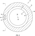
FIG. 3 is another sectional illustration of the probe housing taken along line 3-3 inFIG. 4 . -
FIG. 4 is a cross-sectional illustration of the probe housing. -
FIG. 5 is an illustration of a face-end of the probe housing. -
FIG. 6 is an illustration of a portion of a back-end of the probe housing. -
FIG. 7 is another partial sectional illustration of the measurement system. -
FIG. 8 is a cross-sectional illustration of sensor optics within an optical sheath. -
FIGS. 9 and10 are partial sectional illustrations of the measurement system with various optical sheath arrangements. -
FIG. 11 is a perspective cutaway illustration of a portion of the measurement system. -
FIG. 12 is a side cutaway illustration of a geared turbine engine. -
FIG. 1 illustrates asystem 20 for measuring multiple operational parameters of a rotor. This rotor may be abladed rotor 22 for a gas turbine engine. Examples of thebladed rotor 22 include, but are not limited to, a propulsor rotor (e.g., a fan rotor), a compressor rotor or any other ducted rotor within and/or rotatably driven by the gas turbine engine. The present disclosure, however, is not limited to measuring operational parameters for a bladed rotor, nor to measuring operational parameters for gas turbine engine applications. Themeasurement system 20, for example, may alternatively be configured to measure operational parameters of any rotor in or coupled to various other types of rotational equipment such as, but not limited to, a reciprocating piston engine, a rotary engine, an electric motor and the like. However, for ease of description, themeasurement system 20 is described below with reference to thebladed rotor 22. - The operation parameters may include a blade tip clearance (BTC) and a blade time of arrival (BTOA) for one or
more rotor blades 24 of thebladed rotor 22. The blade tip clearance may be indicative of a (e.g., minimum or average) radial distance between atip 26 of one of therotor blades 24 and aduct wall 28 circumscribing and housing the bladedrotor 22. The blade time of arrival may be indicative of a point in time when the tip 26 (or another portion) of one of therotor blades 24 arrives at or crosses (e.g., passes) a measurement location. The present disclosure, however, is not limited to such exemplary operational parameters. - The
measurement system 20 includes aprobe assembly 30 arranged with theduct wall 28. Thisprobe assembly 30 includes aprobe housing 32, acapacitance probe 34 and anoptical probe 36. - Referring to
FIG. 2 , theprobe housing 32 extends axially along anaxial centerline 38 between and to a face end 40 (e.g., an interior end) of theprobe housing 32 and a back end 42 (e.g., an exterior end) of theprobe housing 32, whichaxial centerline 38 may be or may be parallel with an axial centerline of theprobe housing 32. Referring toFIG. 1 , thehousing face end 40 is configured to face avolume 44 within theduct wall 28; e.g., a flowpath in which thebladed rotor 22 and itsrotor blades 24 are disposed. Briefly, a radial outer peripheral boundary of thevolume 44 inFIG. 1 is formed by aninterior side 46 of theduct wall 28, thehousing face end 40 and asensor face 48 of thecapacitance probe 34. Referring again toFIG. 2 , theprobe housing 32 projects radially out from theaxial centerline 38 to anouter side 50 of theprobe housing 32. - The
probe housing 32 ofFIG. 2 includes ahousing sidewall 52, a housing face-end endwall 54 ("face endwall"), a housing back-end endwall 56 ("back endwall"), aninternal cavity 58 and anoptical channel 60. Referring toFIG. 3 , theprobe housing 32 may also include areceptacle 62 and/or one or more workingfluid channels 64; e.g., cooling and/or purge fluid channels. - Referring to
FIG. 2 , thesidewall 52 extends axially along theaxial centerline 38 between and to the face endwall 54 and theback endwall 56. Thesidewall 52 is also connected to (e.g., formed integral with or attached to) the face endwall 54 and/or theback endwall 56. Thesidewall 52 extends radially between and to aninner side 66 of thesidewall 52 and anouter side 68 of thesidewall 52. The sidewallouter side 68 may be arranged at (e.g., on, adjacent or proximate) the housingouter side 50. The sidewallouter side 68 ofFIG. 2 , for example, is (e.g., slightly) recessed radially inward from the housingouter side 50. Of course, in other embodiments, the sidewallouter side 68 may alternatively be radially aligned with (e.g., at least partially forms) the housingouter side 50. Referring toFIG. 4 , thesidewall 52 extends (e.g., completely) circumferentially around theaxial centerline 38. Thesidewall 52 may thereby be provided with a full-hoop tubular geometry. - The
sidewall 52 may form an outer peripheral boundary of thehousing cavity 58 within theprobe housing 32. Thehousing cavity 58 ofFIG. 4 , for example, projects radially out from theaxial centerline 38 to the sidewallinner side 66. Referring toFIG. 2 , thehousing cavity 58 extends axially along theaxial centerline 38 within theprobe housing 32 / along the sidewallinner side 66 between and to the face endwall 54 and theback endwall 56, whichaxial centerline 38 may be or may be parallel with an axial centerline of thehousing cavity 58. - The
face endwall 54 is disposed at thehousing face end 40. The face endwall 54 ofFIG. 2 , for example, extends axially along theaxial centerline 38 from thesidewall 52 to thehousing face end 40. Theface endwall 54 extends radially out to an outer side aligned with and/or part of the sidewallouter side 68. Theface endwall 54 may form an open end of thehousing cavity 58. The face endwall 54 ofFIG. 2 , for example, includes acavity port 70; e.g., a through-hole. Thiscavity port 70 projects axially along theaxial centerline 38 from thehousing face end 40, through theface endwall 54, to thehousing cavity 58. Thecavity port 70 ofFIG. 2 thereby provides a window (e.g., a pass-through) from an exterior of theprobe housing 32 into thehousing cavity 58. In general, a size (e.g., diameter) of thecavity port 70 is sized smaller than a size (e.g., diameter) of thehousing cavity 58; however, the present disclosure is not limited to such an exemplary arrangement. - The back endwall 56 is disposed at the housing
back end 42. The back endwall 56 ofFIG. 2 , for example, extends axially along theaxial centerline 38 from thesidewall 52 to the housingback end 42. The back endwall 56 projects radially out from theaxial centerline 38 to (or about) the housingouter side 50. The back endwall 56 may form a blind end (e.g., closed-off end) of thehousing cavity 58. The back endwall 56 ofFIG. 2 , for example, extends laterally (e.g., diametrically) across thehousing cavity 58. The back endwall 56 may thereby cap off (e.g., enclose, cover, seal off, etc.) thehousing cavity 58 proximate the housingback end 42. - The
optical channel 60 is formed (e.g., embedded) within theprobe housing 32 and one or more of itshousing members optical channel 60 ofFIG. 2 , for example, is located radially outboard of and separate (e.g., fluidly discrete) from thehousing cavity 58. Theoptical channel 60 extends axially along theaxial centerline 38 in theprobe housing 32 and itshousing members axial centerline 38 is laterally offset from and may be parallel with anaxial centerline 72 of theoptical channel 60. Thisoptical channel centerline 72 may have a straight line trajectory along an entirety of theoptical channel 60. - The
optical channel 60 ofFIG. 2 includes a channel bore 74, a face-end counterbore 76 and a back-end counterbore 78. The channel bore 74 extends axially along theaxial centerline probe housing 32 between and to the face-end counterbore 76 and the back-end counterbore 78. The channel bore 74 ofFIG. 2 , for example, extends axially through thesidewall 52. A face-end portion of the channel bore 74 projects partially into theface endwall 54 to the face-end counterbore 76. A back-end portion of the channel bore 74 projects partially into the back endwall 56 to the back-end counterbore 78. The face-end counterbore 76 projects axially into theface endwall 54 from thehousing face end 40 to the channel bore 74 and its face-end portion. At the intersection between the face-end counterbore 76 and the channel bore 74, an annular shelf projects radially out from an outer periphery of the channel bore 74 to an outer periphery of the face-end counterbore 76. The back-end counterbore 78 projects axially into the back endwall 56 from thereceptacle 62 to the channel bore 74 and its back-end portion. At the intersection between the back-end counterbore 78 and the channel bore 74, an annular shelf projects radially out from the outer periphery of the channel bore 74 to an outer periphery of the back-end counterbore 78. Eachmember optical channel 60 projects radially out from theoptical channel centerline 72 to a (e.g., cylindrical) surface forming its respective outer periphery. - Referring to
FIG. 3 , thereceptacle 62 may be configured as a recess or other indentation in theback endwall 56. Thereceptacle 62 ofFIG. 3 , for example, projects axially along theaxial centerline back end 42 to one or more of thechannels 60 and/or 64. More particularly, thereceptacle 62 ofFIG. 3 extends axially into the back endwall 56 to areceptacle end surface 80, where openings to each of thechannels receptacle end surface 80. Briefly, theaxial centerline FIG. 2 ) from and may be parallel with anaxial centerline 82 of thereceptacle 62. Thereceptacle 62 projects radially out from thereceptacle centerline 82 to a (e.g., cylindrical) surface 84 forming an outer periphery of thereceptacle 62. - Each
fluid channel 64 is formed (e.g., embedded) within theprobe housing 32 and one or more of itshousing members fluid channel 64, for example, is located radially outboard of and separate (e.g., fluidly discrete) from the housing cavity 58 (seeFIG. 3 ). Eachfluid channel 64 extends axially along theaxial centerline probe housing 32 and itshousing members axial centerline fluid channel 64. Each fluid channel centerline may have a straight line trajectory along an entirety of therespective fluid channel 64. Eachfluid channel 64 ofFIG. 3 may be configured as or otherwise include a bore in / through theprobe housing 32. - Referring to
FIGS. 5 and 6 , eachfluid channel 64 is spaced from and fluidly decoupled from theoptical channel 60 between thereceptacle 62 and the volume 44 (seeFIG. 1 ). Theoptical channel 60 ofFIGS. 5 and 6 , for example, is arranged (e.g., circumferentially) between and spaced from thefluid channels 64. The centerlines of thechannels circular reference line 81 extending about theaxial centerline 38; however, the present disclosure is not limited to such an exemplary arrangement. - Referring to
FIG. 1 , theprobe housing 32 and itsmembers duct wall 28. Theprobe housing 32 may thereby extend across theduct wall 28 to thevolume 44. Theprobe housing 32 may be welded, brazed, adhered and/or otherwise bonded to theduct wall 28. Alternatively, theprobe housing 32 may be mechanically fastened to theduct wall 28. For example, referring toFIG. 7 , theprobe housing 32 may also include amount 85; e.g., a mounting flange or tab. Thismount 85 is connected to theback endwall 56, and themount 85 projects laterally out (e.g., is cantilevered) from the back endwall 56 and/orsidewall 52 to a distal end. Themount 85 ofFIG. 7 includes afastener aperture 87 which extends axially through themount 85. With this arrangement, a fastener 89 (e.g., a bolt) may project through thefastener aperture 87 and into a fastener aperture in theduct wall 28 to secure theprobe housing 32 to theduct wall 28. The present disclosure, however, is not limited to the foregoing exemplary probe housing attachment techniques. - Referring to
FIG. 1 , thecapacitance probe 34 is included as part of afirst measurement subsystem 86 of themeasurement system 20. Thisfirst measurement subsystem 86 may be configured as a blade tip clearance (BTC) measurement system for measuring the blade tip clearance. However, it is contemplated thecapacitance probe 34 may also or alternatively be included as part of one or more other measurement system subsystems for measuring one or more other operational parameters associated with thebladed rotor 22. Thecapacitance probe 34 ofFIG. 1 includes acapacitance sensor 88 and an electrical conduit 90 (e.g., a coaxial lead, a triaxial lead, multiple conductors within a common outer sheath, etc.) placing thecapacitance sensor 88 in signal communication with one or more other components 92 (e.g., a signal transducer, a processor, etc.) of thefirst measurement subsystem 86. - The
capacitance sensor 88 is configured as an electrically conductive capacitor member with a capacitor plate. Thiscapacitance sensor 88 is arranged within and attached to theprobe housing 32. Thecapacitance sensor 88 ofFIG. 1 , for example, is at least partially housed within thehousing cavity 58, and its capacitor plate may be seated in thecavity port 70. Thecapacitance sensor 88 extends axially along theaxial centerline 38 to thesensor face 48. Thissensor face 48 is formed by thecapacitance sensor 88 and its capacitor plate. Thecapacitance sensor 88 is electrically coupled to theelectrical conduit 90. A single conductor (or multiple conductors) of theelectrical conduit 90, for example, may project into theprobe housing 32, and this conductor (or multiple conductors) may be directly or indirectly electrically coupled to thecapacitance sensor 88 through a bonded connection, a mechanical connection and/or otherwise. - The
optical probe 36 is included as part of asecond measurement subsystem 94 of themeasurement system 20, whichsecond measurement subsystem 94 may be of a different type and/or configuration than thefirst measurement subsystem 86. Thissecond measurement subsystem 94 may be configured as a blade time of arrival (BTOA) measurement system for measuring the blade time of arrival. However, it is contemplated theoptical probe 36 may also or alternatively be included as part of one or more other measurement system subsystems for measuring one or more other operational parameters associated with thebladed rotor 22. Theoptical probe 36 ofFIG. 1 includessensor optics 96 in signal communication with one or more other components 98 (e.g., a light emission device such as an LED, a light sensing device such as a light receptor, a processor, etc.) of thesecond measurement subsystem 94. Theoptical probe 36 also includes a back-endoptical sheath 100 and a face-endoptical sheath 102. Briefly, eachoptical sheath - Referring to
FIG. 8 , thesensor optics 96 may include a bundle of one or moreoptical fibers optical fiber 104A may be configured for directing light into thevolume 44. Theoptical fibers 104B may be configured for receiving light from thevolume 44. Here, theoptical fiber 104A is centered within the bundle and the otheroptical fibers 104B are distributed circumferentially about theoptical fiber 104A. The present disclosure, however, is not limited to such an exemplary sensor optics arrangement. - Referring to
FIG. 1 , thesensor optics 96 may include a back-end portion 106, a face-end portion 108 and anintermediate portion 110. The back-end portion 106 ofFIG. 1 is housed within (e.g., covered by, extends within, etc.) and may be bonded to the back-endoptical sheath 100. This back-endoptical sheath 100 projects into the back-end counterbore 78 and may be attached (e.g., brazed, adhered or otherwise bonded) to theprobe housing 32 and itsback endwall 56. The face-end portion 108 ofFIG. 1 is housed within (e.g., covered by, extends within, etc.) and may be bonded to the face-endoptical sheath 102. This face-endoptical sheath 102 projects into the face-end counterbore 76 and may be attached (e.g., brazed, adhered or otherwise bonded) to theprobe housing 32 and itsface endwall 54. Theintermediate portion 110 extends axially in theoptical channel 60 and, more particularly extends axially through the channel bore 74 between and to the back-end portion 106 and the face-end portion 108. With this arrangement, thesensor optics 96 and its optical fibers 104 (seeFIG. 8 ) are attached to theprobe housing 32, and extend axially through theprobe housing 32 and itsoptical channel 60 to anend 112 of thesensor optics 96 at thesensor face 48 and/or thehousing face end 40. This provides thesensor optics 96 and, more particularly, each of its optical fibers 104 (seeFIG. 8 ) with an optical line of sight axially through theprobe housing 32 and itsoptical channel 60 into thevolume 44 adjacent thesensor face 48 / thehousing face end 40. - The
probe assembly 30 ofFIG. 1 facilitates arranging multiple different probes at a common location along theduct wall 28. With such an arrangement,multiple probe assemblies 30 and, thus, multiple capacitance probes 34 and multipleoptical probes 36 may be provided for monitoring the samebladed rotor 22. This may increase measurement system accuracy as well as provide redundancy. By contrast, if the capacitance probes 34 and theoptical probes 36 were discretely arranged, only half the number of probes could be utilized when utilizing the same locations as themultiple probe assemblies 30. Furthermore, it may be beneficial to take NSMS measurements at or near aleading edge 114 of therespective rotor blade 24, whereas it may be beneficial to take BTC measurements at an intermediate location (e.g., middle third) along therespective blade tip 26. By laterally offsetting theoptical probe 36 and thecapacitance probe 34, theoptical probe 36 may be positioned at or near the leadingedges 114 of therotor blades 24 and thecapacitance probe 34 may be positioned at or near the intermediate location. - To provide cooling for the
optical probe 36 and/or purging debris out of a gap between the probe(s) 34 and/or 36 and arespective rotor blade 24 and itsblade tip 26, the fluid channels 64 (seeFIGS. 3 and4 ) may be fluidly coupled to a workingfluid source 116; e.g., a cooling and/or purge fluid source. This workingfluid source 116 may be configured as or otherwise includes a working fluid reservoir (e.g., a tank, a pressure vessel, etc.) and/or a working fluid flow regulator (e.g., a valve). The reservoir is configured to contain a working fluid; e.g., a cooling and/or purge fluid. Examples of the working fluid include, but are not limited to, cool dry air, nitrogen (N2) gas, argon (Ar) gas or another inert gas. The flow regulator is configured to selectively direct (e.g., flow, meter, etc.) the working fluid from the reservoir to the fluid channels 64 (seeFIGS. 3 and4 ). This workingfluid source 116 ofFIG. 1 is fluidly coupled to the fluid channels 64 (seeFIGS. 3 and4 ) through at least oneconduit 118; e.g., hypo-tubing, a pipe, a hose, etc. Theconduit 118 projects into thereceptacle 62 and may be attached (e.g., brazed, adhered or otherwise bonded) to theprobe housing 32 and itsback endwall 56. Theconduit 118 may thereby direct the working fluid into the fluid channels 64 (seeFIGS. 3 and4 ) through thereceptacle 62. Here, the back-end portion 106 of thesensor optics 96 and the respective back-endoptical sheath 100 may be routed through theconduit 118 to theprobe housing 32. As the working fluid flows through thefluid channels 64, the working fluid may cool theprobe housing 32 as well as thesensor optics 96. This working fluid may then be directed out of thefluid channels 64 into the gap between the probe(s) 34 and/or 36 and therespective rotor blade 24 and itsblade tip 26 to purge (e.g., displace, flush out, remove) any debris (e.g., electrically conductive contaminants, etc.) in that gap. This purging may clean an end of thesensor optics 96. The purging may also or alternatively maintain dielectric strength between thecapacitance probe 34 and therespective rotor blade 24 and itsblade tip 26 which may otherwise be diminished by the presence of the debris. - In some embodiments, referring to
FIG. 1 , theprobe housing 32 may be divided into ahousing base 120 and ahousing cover 122. Thehousing cover 122 may be removed from thehousing base 120 for installation of thecapacitance sensor 88 into thehousing cavity 58. Thehousing cover 122 may subsequently be bonded and/or otherwise attached to thehousing base 120 to form theprobe housing 32. The present disclosure, however, is not limited to such an exemplary arrangement. - In some embodiments, referring to
FIG. 1 , the face-end portion 108 of thesensor optics 96 may be sheathed. In other embodiments, referring toFIG. 9 , this face-end portion 108 may alternatively be unsheathed. In still other embodiments, referring toFIG. 10 , thesensor optics 96 may be completely sheathed with theoptical sheath 100 axially through theprobe housing 32. - In some embodiments, referring to
FIG. 1 , theconduit 118 and theoptical probe members probe housing 32. In other embodiments, referring toFIG. 11 , theoptical members conduit 118 outside of theprobe housing 32. - In some embodiments, referring to
FIG. 3 , theprobe housing 32 include thefluid channels 64 for directing the working fluid through theprobe housing 32 and to a location proximate the sensor optics end 112 (seeFIG. 1 ). It is contemplated, however, theprobe housing 32 may be configured without thesefluid channels 64 in other embodiments. - The
measurement system 20 is described above as including thecapacitance probe 34 with itscapacitance sensor 88. Themeasurement system 20 of the present disclosure, however, is not limited to such an exemplary field probe and sensor arrangement. The field probe (e.g., element 34), for example, may alternatively be configured as or otherwise include an eddy-current probe. The field sensor (e.g., element 88) may alternatively be configured as or otherwise include an eddy-current sensor. -
FIG. 12 illustrates agas turbine engine 124 with which themeasurement system 20 ofFIG. 1 may be configured. Theturbine engine 124 extends along acenterline axis 126 between anupstream airflow inlet 128 and adownstream airflow exhaust 130. Theturbine engine 124 includes afan section 132, acompressor section 133, acombustor section 134 and aturbine section 135. Thecompressor section 133 includes a low pressure compressor (LPC)section 133A and a high pressure compressor (HPC)section 133B. Theturbine section 135 includes a high pressure turbine (HPT)section 135A and a low pressure turbine (LPT)section 135B. - The engine sections 132-135B are arranged sequentially along the
centerline axis 126 within anengine housing 138. Thisengine housing 138 includes an inner case 140 (e.g., a core case) and an outer case 142 (e.g., a fan case). Theinner case 140 may house one or more of theengine sections 133A-135B; e.g., an engine core. Theouter case 142 may house at least thefan section 132. Theduct wall 28 for themeasurement system 20 ofFIG. 1 may be configured as part of any one of theengine cases engine cases duct wall 28 is part of a blade outer air seal (BOAS), for example. - Each of the
engine sections bladed rotor 22 monitored by themeasurement system 20 ofFIG. 1 may be thefan rotor 144, theLPC rotor 145, theHPC rotor 146 or any other bladed rotor of theturbine engine 124. - The
fan rotor 144 is connected to ageartrain 150, for example, through afan shaft 152. Thegeartrain 150 and theLPC rotor 145 are connected to and driven by theLPT rotor 148 through alow speed shaft 153. TheHPC rotor 146 is connected to and driven by theHPT rotor 147 through ahigh speed shaft 154. The shafts 152-154 are rotatably supported by a plurality ofbearings 156; e.g., rolling element and/or thrust bearings. Each of thesebearings 156 is connected to theengine housing 138 by at least one stationary structure such as, for example, an annular support strut. - During operation, air enters the
turbine engine 124 through theairflow inlet 128. This air is directed through thefan section 132 and into acore flowpath 158 and abypass flowpath 160. Thecore flowpath 158 extends sequentially through theengine sections 133A-135B. The air within thecore flowpath 158 may be referred to as "core air". Thebypass flowpath 160 extends through a bypass duct, which bypasses the engine core. The air within thebypass flowpath 160 may be referred to as "bypass air". - The core air is compressed by the
LPC rotor 145 and theHPC rotor 146 and directed into acombustion chamber 162 of a combustor in thecombustor section 134. Fuel is injected into thecombustion chamber 162 and mixed with the compressed core air to provide a fuel-air mixture. This fuel-air mixture is ignited and combustion products thereof flow through and sequentially cause theHPT rotor 147 and theLPT rotor 148 to rotate. The rotation of theHPT rotor 147 and theLPT rotor 148 respectively drive rotation of theHPC rotor 146 and theLPC rotor 145 and, thus, compression of the air received from a core airflow inlet. The rotation of theLPT rotor 148 also drives rotation of thefan rotor 144, which propels the bypass air through and out of thebypass flowpath 160. The propulsion of the bypass air may account for a majority of thrust generated by theturbine engine 124, e.g., more than seventy-five percent (75%) of engine thrust. The turbine engine of the present disclosure, however, is not limited to the foregoing exemplary thrust ratio. - The
measurement system 20 may be configured with various turbine engines other than the one described above as well as in other types of (e.g., rotational) equipment. Themeasurement system 20, for example, may be configured with a geared turbine engine where a geartrain connects one or more shafts to one or more rotors in a fan section, a compressor section and/or any other engine section. Alternatively, themeasurement system 20 may be configured with a turbine engine configured without a geartrain. The turbine engine may have a single spool, two spools (e.g., seeFIG. 12 ), or more than two spools. The turbine engine may be configured as a turbofan engine, a turbojet engine, a turboprop engine, a turboshaft engine, a propfan engine, a pusher fan engine or any other type of turbine engine. The turbine engine may alternatively be configured as an auxiliary power unit (APU) or an industrial gas turbine engine. The present disclosure therefore is not limited to any particular types or configurations of turbine engines or rotational equipment. - While various embodiments of the present disclosure have been described, it will be apparent to those of ordinary skill in the art that many more embodiments and implementations are possible within the scope of the disclosure. For example, the present disclosure as described herein includes several aspects and embodiments that include particular features. Although these features may be described individually, it is within the scope of the present disclosure that some or all of these features may be combined with any one of the aspects and remain within the scope of the disclosure. Accordingly, the present disclosure is not to be restricted except in light of the attached claims and their equivalents.
Claims (15)
- A measurement system (20), comprising:a probe housing (32) including a sidewall (52), a cavity (58) and a channel (60), the sidewall (52) extending circumferentially around and axially along the cavity (58), and the channel (60) radially outboard of the cavity (58) and extending axially in the sidewall (52);a field probe (34) comprising a field sensor (88) disposed in the cavity (58), the field sensor (88) forming a sensor face (48); andan optical probe (36) configured with an optical line of sight through the channel (60) into a volume (44) adjacent the sensor face (48).
- The measurement system (20) of claim 1, further comprising a blade tip clearance measurement system (86) comprising the field probe (34).
- The measurement system (20) of claim 1 or 2, further comprising a blade time of arrival measurement system (94) comprising the optical probe (36).
- The measurement system (20) of claim 1, 2 or 3, whereinthe optical probe (36) comprises an optical fiber (104) at least partially defining the optical line of sight into the volume (44); andthe optical fiber (104) extends axially in the channel (60).
- The measurement system (20) of claim 4, wherein the optical fiber (104) extends through the probe housing (32) to or into the volume (44).
- The measurement system (20) of claim 4 or 5, whereinthe optical probe (36) further comprises an optical sheath (100);the optical sheath (100) covers a first portion (106) of the optical fiber (104) and is connected to the probe housing (32); anda second portion (110) of the optical fiber (104), within the channel (60), projects out from the optical sheath (100) towards the volume (44).
- The measurement system (20) of claim 6, whereinthe optical sheath (100) is a first optical sheath (100), and the optical probe (36) further comprises a second optical sheath (102);the second optical sheath (102) covers a third portion (108) of the optical fiber (104) and is connected to the probe housing (32); andthe second portion (110) of the optical fiber (104) is between the first portion (106) of the optical fiber (104) and the third portion (108) of the optical fiber (108).
- The measurement system (20) of claim 4 or 5, whereinthe optical probe (36) further comprises an optical sheath (100, 102);the optical sheath (100, 102) covers at least a portion (106, 108, 110) of the optical fiber (104); andthe optical sheath (100, 102) extends through the channel (60) and to or into the volume (44).
- The measurement system (20) of claim 4 or 5, whereinthe optical fiber (104) is a first optical fiber (104A), and the optical probe (36) further comprises a second optical fiber (104B) at least partially defining a second optical line of sight into the volume (44); andthe second optical fiber (104B) extends axially in the channel (60).
- The measurement system (20) of any preceding claim, whereinthe channel (60) is an optical channel (60), and the probe housing (32) further includes a fluid channel (64) adjacent the optical channel (60) within the sidewall (52); andthe fluid channel (64) is radially outboard of the cavity (58) and extends axially in the sidewall (52).
- The measurement system (20) of claim 10, further comprising a working fluid source (116) fluidly coupled with the fluid channel (64).
- The measurement system (20) of claim 10 or 11, whereinthe probe housing (32) further includes a receptacle (62) at an end (42) of the probe housing (32); andthe optical channel (60) and the fluid channel (64) each project axially into the probe housing (32) from the receptacle (62).
- The measurement system (20) of claim 10, 11 or 12, whereinthe fluid channel (64) is a first fluid channel (64), and the probe housing (32) further includes a second fluid channel (64) adjacent the optical channel (60) within the sidewall (52); andthe second fluid channel (64) projects axially into the probe housing (32) from a or the receptacle (62),optionally wherein the optical channel (60) is laterally between the first fluid channel (64) and the second fluid channel (64).
- The measurement system (20) of any of claims 10 to 13, wherein the optical channel (60) and the fluid channel (64) each extend axially in the probe housing (32) to an end (42) of the probe housing (32) at the sensor face (48).
- The measurement system (20) of any preceding claim, whereinthe probe housing (32) further includes a mount (85) projecting out from the sidewall (52); anda fastener aperture (87) extends axially through the mount (85).
Applications Claiming Priority (1)
| Application Number | Priority Date | Filing Date | Title |
|---|---|---|---|
| US18/121,430 US12553796B2 (en) | 2023-03-14 | 2023-03-14 | Measurement system having a probe for measuring parameters of a turbine engine |
Publications (1)
| Publication Number | Publication Date |
|---|---|
| EP4431862A1 true EP4431862A1 (en) | 2024-09-18 |
Family
ID=90365404
Family Applications (1)
| Application Number | Title | Priority Date | Filing Date |
|---|---|---|---|
| EP24163591.1A Pending EP4431862A1 (en) | 2023-03-14 | 2024-03-14 | Multi-measurement probe assembly |
Country Status (2)
| Country | Link |
|---|---|
| US (1) | US12553796B2 (en) |
| EP (1) | EP4431862A1 (en) |
Families Citing this family (1)
| Publication number | Priority date | Publication date | Assignee | Title |
|---|---|---|---|---|
| US12455213B2 (en) * | 2023-02-01 | 2025-10-28 | Rtx Corporation | Measurement system having a capacitance probe and an optical probe |
Citations (4)
| Publication number | Priority date | Publication date | Assignee | Title |
|---|---|---|---|---|
| US20050280412A1 (en) * | 2002-02-13 | 2005-12-22 | Roeseler Corydon C | Blade detection sensor having an active cooling system |
| US20190383594A1 (en) * | 2018-06-19 | 2019-12-19 | United Technologies Corporation | Systems and methods for pseudo-triaxial capacitance probe assemblies |
| DE102019102965A1 (en) * | 2019-02-06 | 2020-08-06 | Physik Instrumente (Pi) Gmbh & Co. Kg | Holding device for an optical fiber |
| CN113310421A (en) * | 2021-06-11 | 2021-08-27 | 中国工程物理研究院流体物理研究所 | Optical fiber probe for measuring tip clearance of turbine engine |
Family Cites Families (15)
| Publication number | Priority date | Publication date | Assignee | Title |
|---|---|---|---|---|
| DE3044242A1 (en) * | 1979-12-11 | 1981-09-03 | Smiths Industries Ltd., London | DISPLAY SYSTEM FOR DISPLAYING THE DISTANCE OF THE BLADES OF A TURBINE TO A REFERENCE POINT |
| US4666297A (en) * | 1985-11-14 | 1987-05-19 | United Technologies Corporation | Dual spectra optical pyrometer having an air pressure sensitive shutter |
| US5349850A (en) * | 1992-11-19 | 1994-09-27 | General Electric Company | Instrumentation light probe holder |
| GB2449709A (en) | 2007-06-02 | 2008-12-03 | Rolls Royce Plc | Method and apparatus for determining a clearance between relatively movable components |
| US9709463B2 (en) * | 2012-01-31 | 2017-07-18 | Siemens Energy, Inc. | Method and system for surface profile inspection of off-line industrial gas turbines and other power generation machinery |
| US9366586B2 (en) * | 2013-03-14 | 2016-06-14 | United Technologies Corporation | High temperature uncooled optical probe |
| US9513117B2 (en) * | 2013-10-02 | 2016-12-06 | Siemens Energy, Inc. | Situ blade mounted tip gap measurement for turbines |
| US9681107B2 (en) * | 2014-05-22 | 2017-06-13 | Siemens Energy, Inc. | Flexible tether position tracking camera inspection system for visual inspection of off line industrial gas turbines and other power generation machinery |
| US10041371B1 (en) * | 2015-02-06 | 2018-08-07 | Siemens Energy, Inc. | In-situ measurement of blade tip-to-shroud gap in turbine engine |
| US10768059B2 (en) * | 2018-02-16 | 2020-09-08 | Raytheon Technologies Corporation | Embedded optical probe for gas turbine engine |
| PL236751B1 (en) * | 2018-06-18 | 2021-02-08 | Inphotech Spolka Z Ograniczona Odpowiedzialnoscia | Waveguide sensor |
| CN113358205A (en) | 2021-04-26 | 2021-09-07 | 西安交通大学 | Measuring device and measuring method for synchronously detecting blade vibration and blade tip clearance |
| CN114894858B (en) | 2022-03-23 | 2024-08-13 | 燕山大学 | Non-invasive photoelectric combined sensor, control system and measurement method thereof |
| US12455213B2 (en) * | 2023-02-01 | 2025-10-28 | Rtx Corporation | Measurement system having a capacitance probe and an optical probe |
| US20240310599A1 (en) * | 2023-03-14 | 2024-09-19 | Raytheon Technologies Corporation | Coupling optical fibers and fluid passages |
-
2023
- 2023-03-14 US US18/121,430 patent/US12553796B2/en active Active
-
2024
- 2024-03-14 EP EP24163591.1A patent/EP4431862A1/en active Pending
Patent Citations (4)
| Publication number | Priority date | Publication date | Assignee | Title |
|---|---|---|---|---|
| US20050280412A1 (en) * | 2002-02-13 | 2005-12-22 | Roeseler Corydon C | Blade detection sensor having an active cooling system |
| US20190383594A1 (en) * | 2018-06-19 | 2019-12-19 | United Technologies Corporation | Systems and methods for pseudo-triaxial capacitance probe assemblies |
| DE102019102965A1 (en) * | 2019-02-06 | 2020-08-06 | Physik Instrumente (Pi) Gmbh & Co. Kg | Holding device for an optical fiber |
| CN113310421A (en) * | 2021-06-11 | 2021-08-27 | 中国工程物理研究院流体物理研究所 | Optical fiber probe for measuring tip clearance of turbine engine |
Also Published As
| Publication number | Publication date |
|---|---|
| US20240310246A1 (en) | 2024-09-19 |
| US12553796B2 (en) | 2026-02-17 |
Similar Documents
| Publication | Publication Date | Title |
|---|---|---|
| EP3623790B1 (en) | Embedded non-intrusive stress measurement system probe | |
| EP3543473A2 (en) | Flush-mount combined static pressure and temperature probe | |
| US10982561B2 (en) | Integrated gas turbine engine support and sensor | |
| US11175187B2 (en) | Air temperature sensor having a bushing | |
| EP4431862A1 (en) | Multi-measurement probe assembly | |
| US20140064926A1 (en) | High temperature split-face probe | |
| EP3351734A1 (en) | Fan blade with anode and method for galvanic corrosion mitigation | |
| EP4411313A1 (en) | Multi-measurement probe assembly | |
| EP4206637A1 (en) | Vacuum testing a seal within a gas turbine engine structure | |
| SG10202100891RA (en) | Engine inspection and maintenance tool | |
| US20230387750A1 (en) | Gas turbine engine with electric machine in engine core | |
| EP3502442B1 (en) | Concentric power takeoff transmission | |
| CN115163201B (en) | A device and system for testing a high-pressure turbine rotor of an aircraft engine | |
| US9181818B2 (en) | Thermally constrained high temperature optical fiber holder | |
| EP3748134B1 (en) | Vane airfoil shapes for embedded members | |
| US12436179B2 (en) | Identifying fault in torque signal / torque sensor for aircraft system | |
| US12297743B2 (en) | Gas turbine engine having a sensor assembly to detect torsional vibration | |
| EP4134643A1 (en) | Non-contact high temperature measurement system | |
| US20230220785A1 (en) | Radial outward bearing support for a rotating structure of a turbine engine | |
| US20220389820A1 (en) | Anti-vortex tube retaining ring and bore basket | |
| US11041404B2 (en) | In-situ wireless monitoring of engine bearings | |
| US11624662B2 (en) | Exhaust gas temperature sensor | |
| US12331646B1 (en) | Air seal for a turbine engine | |
| US20250092794A1 (en) | Instrumented stator with extended internal passages | |
| EP4375485A1 (en) | Gas turbine engine airfoil with extended laminar flow |
Legal Events
| Date | Code | Title | Description |
|---|---|---|---|
| PUAI | Public reference made under article 153(3) epc to a published international application that has entered the european phase |
Free format text: ORIGINAL CODE: 0009012 |
|
| STAA | Information on the status of an ep patent application or granted ep patent |
Free format text: STATUS: THE APPLICATION HAS BEEN PUBLISHED |
|
| AK | Designated contracting states |
Kind code of ref document: A1 Designated state(s): AL AT BE BG CH CY CZ DE DK EE ES FI FR GB GR HR HU IE IS IT LI LT LU LV MC ME MK MT NL NO PL PT RO RS SE SI SK SM TR |
|
| STAA | Information on the status of an ep patent application or granted ep patent |
Free format text: STATUS: REQUEST FOR EXAMINATION WAS MADE |
|
| 17P | Request for examination filed |
Effective date: 20250318 |