EP4431841A1 - Two-stage cascade refrigeration cycle device - Google Patents
Two-stage cascade refrigeration cycle device Download PDFInfo
- Publication number
- EP4431841A1 EP4431841A1 EP24719036.6A EP24719036A EP4431841A1 EP 4431841 A1 EP4431841 A1 EP 4431841A1 EP 24719036 A EP24719036 A EP 24719036A EP 4431841 A1 EP4431841 A1 EP 4431841A1
- Authority
- EP
- European Patent Office
- Prior art keywords
- condenser
- heat exchanger
- heat
- refrigerant
- heat transfer
- Prior art date
- Legal status (The legal status is an assumption and is not a legal conclusion. Google has not performed a legal analysis and makes no representation as to the accuracy of the status listed.)
- Pending
Links
Images



Classifications
-
- F—MECHANICAL ENGINEERING; LIGHTING; HEATING; WEAPONS; BLASTING
- F25—REFRIGERATION OR COOLING; COMBINED HEATING AND REFRIGERATION SYSTEMS; HEAT PUMP SYSTEMS; MANUFACTURE OR STORAGE OF ICE; LIQUEFACTION SOLIDIFICATION OF GASES
- F25B—REFRIGERATION MACHINES, PLANTS OR SYSTEMS; COMBINED HEATING AND REFRIGERATION SYSTEMS; HEAT PUMP SYSTEMS
- F25B1/00—Compression machines, plants or systems with non-reversible cycle
-
- F—MECHANICAL ENGINEERING; LIGHTING; HEATING; WEAPONS; BLASTING
- F25—REFRIGERATION OR COOLING; COMBINED HEATING AND REFRIGERATION SYSTEMS; HEAT PUMP SYSTEMS; MANUFACTURE OR STORAGE OF ICE; LIQUEFACTION SOLIDIFICATION OF GASES
- F25B—REFRIGERATION MACHINES, PLANTS OR SYSTEMS; COMBINED HEATING AND REFRIGERATION SYSTEMS; HEAT PUMP SYSTEMS
- F25B7/00—Compression machines, plants or systems, with cascade operation, i.e. with two or more circuits, the heat from the condenser of one circuit being absorbed by the evaporator of the next circuit
-
- F—MECHANICAL ENGINEERING; LIGHTING; HEATING; WEAPONS; BLASTING
- F25—REFRIGERATION OR COOLING; COMBINED HEATING AND REFRIGERATION SYSTEMS; HEAT PUMP SYSTEMS; MANUFACTURE OR STORAGE OF ICE; LIQUEFACTION SOLIDIFICATION OF GASES
- F25B—REFRIGERATION MACHINES, PLANTS OR SYSTEMS; COMBINED HEATING AND REFRIGERATION SYSTEMS; HEAT PUMP SYSTEMS
- F25B13/00—Compression machines, plants or systems, with reversible cycle
-
- F—MECHANICAL ENGINEERING; LIGHTING; HEATING; WEAPONS; BLASTING
- F25—REFRIGERATION OR COOLING; COMBINED HEATING AND REFRIGERATION SYSTEMS; HEAT PUMP SYSTEMS; MANUFACTURE OR STORAGE OF ICE; LIQUEFACTION SOLIDIFICATION OF GASES
- F25B—REFRIGERATION MACHINES, PLANTS OR SYSTEMS; COMBINED HEATING AND REFRIGERATION SYSTEMS; HEAT PUMP SYSTEMS
- F25B39/00—Evaporators; Condensers
- F25B39/04—Condensers
-
- F—MECHANICAL ENGINEERING; LIGHTING; HEATING; WEAPONS; BLASTING
- F25—REFRIGERATION OR COOLING; COMBINED HEATING AND REFRIGERATION SYSTEMS; HEAT PUMP SYSTEMS; MANUFACTURE OR STORAGE OF ICE; LIQUEFACTION SOLIDIFICATION OF GASES
- F25B—REFRIGERATION MACHINES, PLANTS OR SYSTEMS; COMBINED HEATING AND REFRIGERATION SYSTEMS; HEAT PUMP SYSTEMS
- F25B9/00—Compression machines, plants or systems, in which the refrigerant is air or other gas of low boiling point
- F25B9/002—Compression machines, plants or systems, in which the refrigerant is air or other gas of low boiling point characterised by the refrigerant
- F25B9/008—Compression machines, plants or systems, in which the refrigerant is air or other gas of low boiling point characterised by the refrigerant the refrigerant being carbon dioxide
-
- F—MECHANICAL ENGINEERING; LIGHTING; HEATING; WEAPONS; BLASTING
- F28—HEAT EXCHANGE IN GENERAL
- F28F—DETAILS OF HEAT-EXCHANGE AND HEAT-TRANSFER APPARATUS, OF GENERAL APPLICATION
- F28F1/00—Tubular elements; Assemblies of tubular elements
- F28F1/10—Tubular elements and assemblies thereof with means for increasing heat-transfer area, e.g. with fins, with projections, with recesses
- F28F1/12—Tubular elements and assemblies thereof with means for increasing heat-transfer area, e.g. with fins, with projections, with recesses the means being only outside the tubular element
- F28F1/24—Tubular elements and assemblies thereof with means for increasing heat-transfer area, e.g. with fins, with projections, with recesses the means being only outside the tubular element and extending transversely
- F28F1/32—Tubular elements and assemblies thereof with means for increasing heat-transfer area, e.g. with fins, with projections, with recesses the means being only outside the tubular element and extending transversely the means having portions engaging further tubular elements
- F28F1/325—Fins with openings
-
- F—MECHANICAL ENGINEERING; LIGHTING; HEATING; WEAPONS; BLASTING
- F25—REFRIGERATION OR COOLING; COMBINED HEATING AND REFRIGERATION SYSTEMS; HEAT PUMP SYSTEMS; MANUFACTURE OR STORAGE OF ICE; LIQUEFACTION SOLIDIFICATION OF GASES
- F25B—REFRIGERATION MACHINES, PLANTS OR SYSTEMS; COMBINED HEATING AND REFRIGERATION SYSTEMS; HEAT PUMP SYSTEMS
- F25B2339/00—Details of evaporators; Details of condensers
- F25B2339/04—Details of condensers
-
- F—MECHANICAL ENGINEERING; LIGHTING; HEATING; WEAPONS; BLASTING
- F25—REFRIGERATION OR COOLING; COMBINED HEATING AND REFRIGERATION SYSTEMS; HEAT PUMP SYSTEMS; MANUFACTURE OR STORAGE OF ICE; LIQUEFACTION SOLIDIFICATION OF GASES
- F25B—REFRIGERATION MACHINES, PLANTS OR SYSTEMS; COMBINED HEATING AND REFRIGERATION SYSTEMS; HEAT PUMP SYSTEMS
- F25B2400/00—Component parts or details not otherwise provided for in this subclass
- F25B2400/12—Inflammable refrigerants
- F25B2400/121—Inflammable refrigerants using R1234
Definitions
- the present disclosure relates to a cascade refrigeration cycle apparatus.
- Patent Literature 1 ( WO 2014/181399 A ) there is known a cascade refrigeration cycle apparatus in which a cycle using CO 2 as a refrigerant and a supercooling cycle for exchanging heat with CO 2 are combined to expand a supercooling region of a cycle using CO 2 and improve efficiency.
- a cascade refrigeration cycle apparatus comprises a fan, a first cycle, a second cycle, and a heat exchanger.
- a first refrigerant having a critical point of 40°C or higher circulates.
- the first cycle includes a condenser in which air supplied by the fan and the first refrigerant exchange heat.
- carbon dioxide as a second refrigerant circulates.
- the second cycle includes a radiator in which air supplied by the fan and the second refrigerant exchange heat.
- the first refrigerant and the second refrigerant exchange heat is disposed on a windward side of the radiator in a first direction that is a direction of an airflow generated by the fan.
- the cascade refrigeration cycle apparatus can improve a heat exchange efficiency in the condenser.
- CO 2 flowing through the radiator in a low-side cycle at least locally exchanges heat with air having exchanged heat with the first refrigerant.
- CO 2 is a refrigerant having a relatively poor heat exchange efficiency. Therefore, even if the air heated by exchanging heat with the first refrigerant is supplied to the radiator, the influence on the overall efficiency is smaller than when the air heated by exchanging heat with CO 2 exchanges heat with the first refrigerant flowing through the condenser in the first cycle.
- a cascade refrigeration cycle apparatus is the cascade refrigeration cycle apparatus according to the first aspect, in which the radiator includes a first region overlapping the condenser in the first direction and a second region not overlapping the condenser in the first direction.
- the radiator has a region not overlapping the condenser in a direction of airflow. Therefore, even the radiator installed on a leeward side of the condenser can achieve a relatively high heat exchange efficiency in the region not overlapping the condenser.
- a cascade refrigeration cycle apparatus is the cascade refrigeration cycle apparatus according to the first or second aspect, in which the condenser has a first inlet through which the first refrigerant flows into.
- the radiator has a second inlet through which the second refrigerant flows into. The second inlet is disposed near the first inlet.
- the first refrigerant flowing through the first inlet of the condenser located the most upstream has the highest temperature. Therefore, the temperature of air that has exchanged heat with the first refrigerant flowing through the first inlet of the condenser tends to be relatively high.
- the second refrigerant flowing through the radiator exchanges heat with such relatively high-temperature air, the heat exchange efficiency tends to decrease as compared with the case of exchanging heat with relatively low-temperature air.
- the inlet of the radiator and the inlet of the condenser are disposed close to each other in order to reduce such a decrease in heat exchange efficiency.
- the temperature of the second refrigerant is the highest at the second inlet of the radiator located the most upstream. Therefore, even when the temperature of the air that has exchanged heat with the first refrigerant flowing near the first inlet of the condenser is relatively high, a decrease in the heat exchange efficiency of the radiator is easily reduced.
- a cascade refrigeration cycle apparatus is the cascade refrigeration cycle apparatus according to any of the first to third aspects, in which the fan includes an impeller.
- the condenser at least partially overlaps the impeller when viewed in an axial direction of the impeller.
- a cascade refrigeration cycle apparatus is the cascade refrigeration cycle apparatus according to any of the first to fourth aspects, in which the condenser includes a first heat transfer tube.
- the radiator includes a second heat transfer tube.
- the first heat transfer tube and the second heat transfer tube are inserted into a fin being common to each other.
- the fin is provided with a slit formed between a through portion of the first heat transfer tube and a through portion of the second heat transfer tube.
- a cascade refrigeration cycle apparatus is the cascade refrigeration cycle apparatus the fifth aspect, in which the condenser includes a first tube plate made of metal.
- the first heat transfer tube is inserted through the first tube plate, and the first tube plate supports the first heat transfer tube.
- the radiator further includes a second tube plate made of metal.
- the second heat transfer tube is inserted through the second tube plate, and the second tube plate supports the second heat transfer tube.
- the first tube plate and the second tube plate are separate members.
- a cascade refrigeration cycle apparatus is the cascade refrigeration cycle apparatus according to any of the first, second, third, fifth, or sixth aspect, in which the fan is disposed above the condenser and the radiator. In the fan, the condenser is disposed at a position at least partially overlapping an upper part of the radiator.
- a wind speed increases at an upper part close to the fan.
- the condenser is disposed at a position at least partially overlapping the upper part of the radiator. Accordingly, heat of the first refrigerant can be efficiently exchanged in the condenser.
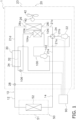
- FIG. 1 is a schematic configuration diagram of the cascade refrigeration cycle apparatus 1.
- the cascade refrigeration cycle apparatus 1 is an apparatus that performs vapor compression refrigeration cycle operation to cool or heat a temperature adjustment target.
- the cascade refrigeration cycle apparatus 1 cools or heats air in a room of an office building or the like as a temperature adjustment target to perform cooling or heating of the room of the office building or the like.
- the temperature adjustment target of the cascade refrigeration cycle apparatus 1 is air.
- the cascade refrigeration cycle apparatus of the present disclosure may be a device that cools or heats water, a heat medium, or the like that is the temperature adjustment target.
- the cascade refrigeration cycle apparatus 1 cools and heats a room in an office building or the like, but the cascade refrigeration cycle apparatus may be an apparatus dedicated to cooling.
- the cascade refrigeration cycle apparatus 1 mainly includes a vapor compression first cycle 100, a vapor compression second cycle 10, a fan 40, and a control device 90.
- the first cycle 100 is a refrigerant circuit in which a first refrigerant having a higher critical point than a second refrigerant used in the second cycle 10 circulates.
- the first refrigerant is a refrigerant having a critical point of 40°C or higher.
- the first refrigerant is preferably a refrigerant having a critical point of 50°C or higher.
- the first refrigerant preferably has a relatively low global warming potential.
- the type of the refrigerant is not limited, the first refrigerant is, for example, any single refrigerant of R290 (critical point 370°C), R1234yf (critical point 95°C), R1234ze (critical point 154°C), or R32 (critical point 72°C), or a mixed refrigerant including the above refrigerants.
- the second cycle 10 is a refrigerant circuit through which a refrigerant including carbon dioxide (CO 2 ) circulates as the second refrigerant.
- the critical point of CO 2 is 31.1°C.
- the refrigerant circulating in the second cycle 10 is a single refrigerant of CO 2 .
- the first cycle 100 and the second cycle 10 are thermally connected via a cascade heat exchanger 30.
- the cascade heat exchanger 30 the first refrigerant circulating in the first cycle 100 and the second refrigerant circulating in the second cycle 10 exchange heat.
- the cascade refrigeration cycle apparatus 1 includes the first cycle 100 in addition to the second cycle 10 for the following reasons.
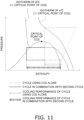
- CO 2 has an excellent characteristic of having a small global warming potential but has a characteristic of having a low critical point. Therefore, in a case where only the second cycle using CO 2 as the second refrigerant is used in the refrigeration cycle apparatus, if a cooling operation is performed by using the heat exchanger on a heat source side as a radiator under a condition where the temperature of heat source air is high (a condition where the temperature of the heat source air exceeds the critical point of CO 2 ), the CO 2 does not change in phase, and thus the cycle becomes a cycle as indicated by a broken line in FIG. 11 . In such a cycle, since an enthalpy difference due to heat exchange is small, the obtained cooling capacity becomes relatively small as indicated by a double-headed arrow of a broken line in FIG. 11 , and the efficiency is deteriorated.
- the first cycle having a relatively high critical point is used for subcooling the second refrigerant in addition to the second cycle using CO 2 as the second refrigerant. Therefore, the cycle can be improved as indicated by a one-dot chain line in the Mollier diagram of FIG. 11 , and the obtained cooling capacity can be expanded as indicated by a double-headed arrow of a one-dot chain line in FIG. 11 .
- the fan 40 is a device that generates an airflow in order to supply air as a heat source (heat source air) to a condenser 104 in the first cycle 100 and a first heat exchanger 26 in the second cycle 10.
- the cascade refrigeration cycle apparatus 1 is divided into a heat source unit 20 and a utilization unit 50.
- the heat source unit 20 and the utilization unit 50 are connected via connection pipes 12 and 14 constituting the second cycle 10.
- the heat source unit 20 includes a housing 23.
- the housing 23 accommodates various devices constituting the first cycle 100, some of various devices constituting the second cycle 10, the fan 40, and the like.
- the heat source unit 20 is installed on, but not limited to, a rooftop of a building such as an office building in which the cascade refrigeration cycle apparatus 1 is installed, near a wall of a building, or the like.
- the utilization unit 50 includes a housing 51.
- the housing 51 accommodates a second heat exchanger 52 of the second cycle 10, a fan (not illustrated) that supplies air to the second heat exchanger 52, and the like.
- the utilization unit 50 is installed, for example, in an air conditioning target space or near the air conditioning target space (for example, a ceiling space or the like of the air conditioning target space).
- the cascade refrigeration cycle apparatus 1 may include a plurality of utilization units 50 having the second heat exchangers 52 connected in parallel to each other.
- the control device 90 is electrically connected to various devices constituting the second cycle 10, various devices constituting the first cycle 100, and the fan 40 and controls operations of the devices electrically connected to the control device 90.
- the first cycle 100, the second cycle 10, the fan 40, the control device 90, and the heat source unit 20 will be described in detail.
- the first cycle 100 the first refrigerant circulates.
- the first cycle 100 is mainly used for subcooling the second refrigerant flowing in the second cycle during the cooling operation.
- the first cycle 100 mainly includes a compressor 102, the condenser 104, an expansion mechanism 106, and the cascade heat exchanger 30 which are connected by pipes.
- the first refrigerant discharged from the compressor 102 flows through the condenser 104, the expansion mechanism 106, and the cascade heat exchanger 30 in this order, and returns to a suction side of the compressor 102.
- the compressor 102 compresses the first refrigerant.
- the compressor 102 is a variable operating capacity compressor including an inverter-controlled motor.
- the compressor 102 may be a compressor having a constant operating capacity.
- the compressor 102 is, for example, a scroll compressor or a rotary compressor.
- the type of the compressor 102 is not limited to the above examples, and may be appropriately selected.
- the air (heat source air) supplied by the fan 40 and the first refrigerant exchange heat.
- the first refrigerant obtains cold energy from the heat source air.
- the condenser 104 is, for example, a fin-and-tube heat exchanger having a large number of heat transfer tubes and fins.
- the expansion mechanism 106 decompresses the first refrigerant.
- the expansion mechanism 106 is, for example, an electronic expansion valve having a variable opening degree.
- the expansion mechanism 106 is not limited to this example, and may be an automatic temperature expansion valve having a temperature sensitive cylinder or a capillary tube.
- the cascade heat exchanger 30 causes the first refrigerant and the second refrigerant to exchange heat with each other without mixing the first refrigerant and the second refrigerant.
- the cascade heat exchanger 30 is, for example, a plate heat exchanger.
- the cascade heat exchanger 30 includes a first flow path 32 constituting a part of the first cycle 100 and a second flow path 34 constituting a part of the second cycle 10.
- the first refrigerant flowing through first flow path 32 and a second fluid flowing through second flow path 34 exchange heat, and the second fluid is cooled by the first fluid.
- One end of the first flow path 32 is connected to the expansion mechanism 106 via a refrigerant pipe, and the other end is connected to the suction side of the compressor 102 via a refrigerant pipe.
- the second refrigerant circulates.
- the second refrigerant circulating in the second cycle 10 is used for cooling and heating the air in a space as the temperature adjustment target.
- the second cycle 10 mainly includes a compressor 22, a switching mechanism 24, the first heat exchanger 26, the cascade heat exchanger 30, an expansion mechanism 28, and the second heat exchanger 52.
- the compressor 22 compresses the second refrigerant.
- the compressor 22 is a variable operating capacity compressor including an inverter-controlled motor.
- the compressor 22 may be a compressor having a constant operating capacity.
- the compressor 22 is, for example, a scroll compressor or a rotary compressor.
- the type of the compressor 22 is not limited to the above examples, and may be appropriately selected.
- the switching mechanism 24 is a mechanism that switches a state of the second cycle 10 between a first state and a second state.
- the first heat exchanger 26 functions as a radiator for the second refrigerant
- the second heat exchanger 52 functions as an evaporator for the second refrigerant.
- the first heat exchanger 26 functions as an evaporator for the second refrigerant
- the second heat exchanger 52 functions as a radiator for the second refrigerant.
- the switching mechanism 24 is, for example, a four-way switching valve.
- the switching mechanism 24 connects a discharge pipe 21b and a first pipe 21c, and connects a suction pipe 21a and a third pipe 21e.
- the switching mechanism 24 connects the discharge pipe 21b and the third pipe 21e, and connects the suction pipe 21a and the first pipe 21c.
- the discharge pipe 21b is a pipe that connects a discharge side of the compressor 22 and the switching mechanism 24.
- the first pipe 21c is a pipe that connects the switching mechanism 24 and the first heat exchanger 26.
- the suction pipe 21a is a pipe that connects the suction side of the compressor 22 and the switching mechanism 24.
- Third pipe 21e is a pipe that connects the switching mechanism 24 and the connection pipe 14.
- the air (heat source air) supplied by the fan 40 and the second refrigerant exchange heat.
- the first heat exchanger 26 functions as a radiator, and the second refrigerant obtains cold energy from the heat source air in the first heat exchanger 26.
- the first heat exchanger 26 functions as an evaporator, and the second refrigerant obtains thermal energy from the heat source air in the first heat exchanger 26.
- the first heat exchanger 26 is, for example, a fin-and-tube heat exchanger having a large number of heat transfer tubes and fins.
- the cascade heat exchanger 30 is a heat exchanger that causes the first refrigerant and the second refrigerant to exchange heat without mixing with each other, and the second flow path 34 of the cascade heat exchanger 30 constitutes a part of the second cycle 10.
- the cascade heat exchanger 30 is disposed in the second pipe 21d.
- the second pipe 21d is a pipe that connects the first heat exchanger 26 and the connection pipe 12 in the second cycle 10.
- the expansion mechanism 28 decompresses the second refrigerant.
- the expansion mechanism 28 is disposed on the second pipe 21d between the cascade heat exchanger 30 and a connecting portion between the second pipe 21d and the connection pipe 12.
- the expansion mechanism 28 is, for example, an electronic expansion valve having a variable opening degree.
- the expansion mechanism 28 is not limited to this example, and may be an automatic temperature expansion valve having a temperature sensitive cylinder or a capillary tube.
- the second heat exchanger 52 the second refrigerant and air in the air conditioning target space exchange heat.
- the second heat exchanger 52 is accommodated in the housing 51.
- the air in the air conditioning target space is supplied to the second heat exchanger 52 by a fan (not illustrated) disposed in the housing 51.
- the air in the air conditioning target space supplied by the fan and the second refrigerant exchange heat.
- the state of the second cycle 10 is the first state
- the second heat exchanger 52 functions as an evaporator, and the air in the air conditioning target space is cooled by the second refrigerant in the second heat exchanger 52.
- the second heat exchanger 52 When the state of the second cycle 10 is the second state, the second heat exchanger 52 functions as a radiator, and the air in the air conditioning target space is heated by the second refrigerant in the second heat exchanger 52.
- the second heat exchanger 52 is, for example, a fin-and-tube heat exchanger having a large number of heat transfer tubes and fins.
- the fan 40 is accommodated in the housing 23 of the heat source unit 20.
- the fan 40 rotates an impeller 42 about an axis O by a motor (not illustrated) to supply the heat source air to the condenser 104 in the first cycle 100 and the first heat exchanger 26 in the second cycle 10 accommodated in the housing 23 of the heat source unit 20.
- the fan 40 is, for example, an axial flow fan, although the type is not limited. In the present embodiment, in particular, the fan 40 is, for example, a propeller fan.
- the control device 90 is a device that controls the operation of the cascade refrigeration cycle apparatus 1.
- the control device 90 is electrically connected to the compressor 102 and the expansion mechanism 106 in the first cycle 100, the compressor 22, the switching mechanism 24 and the expansion mechanism 28 in the second cycle 10, and the fan 40 (see the broken lines in FIG. 1 ).
- the control device 90 controls the operation of the cascade refrigeration cycle apparatus 1 by controlling the operation of these electrically connected devices.
- FIG. 1 illustrates the control device 90, for convenience, at a position away from the heat source unit 20, the utilization unit 50, and the like.
- the control device 90 includes an arithmetic and control unit and a storage.
- a processor such as a CPU can be used.
- the arithmetic and control unit reads a program stored in the storage, and controls the operation of the cascade refrigeration cycle apparatus 1 in accordance with this program.
- the control device 90 controls the operation of the switching mechanism 24 to set the state of the second cycle 10 to the second state and operate the compressor 22.
- the control device 90 controls an operating capacity of the motor of the compressor 22 on the basis of a measurement result of a sensor (a sensor that measures a temperature and a pressure of the second refrigerant at an appropriate location in the second cycle 10, or a sensor that measures a temperature of the heat source air, the sensor is referred to as a first sensor hereinafter), not illustrated, disposed at an appropriate location.
- the control device 90 operates the motors of the fan 40 and a fan of the utilization unit 50 at a predetermined number of rotations. Furthermore, the control device 90 controls the opening degree of the electronic expansion valve as the expansion mechanism 28 on the basis of the measurement result of the first sensor.
- the control device 90 controls the operation of the switching mechanism 24 to set the state of the second cycle 10 to the first state and operate the compressor 22.
- the control device 90 controls the operating capacity of the motor of the compressor 22 on the basis of the measurement result of the first sensor.
- the control device 90 operates the motors of the fan 40 and a fan of the utilization unit 50 at a predetermined number of rotations. Furthermore, the control device 90 controls the opening degree of the electronic expansion valve as the expansion mechanism 28 on the basis of the measurement result of the first sensor.
- control device 90 operates the compressor 102 when causing the cascade refrigeration cycle apparatus 1 to perform the cooling operation.
- the control device 90 may operate the compressor 102 whenever causing the cascade refrigeration cycle apparatus 1 to perform the cooling operation.
- the control device 90 may operate the compressor 102, for example, when the temperature of the heat source air (outside air) is higher than a predetermined temperature.
- the control device 90 controls an operating capacity of the motor of the compressor 102 on the basis of a measurement result of a sensor (a sensor that measures a temperature and a pressure of the first refrigerant at an appropriate location in the first cycle 100, or a sensor that measures a temperature of the heat source air, the sensor is referred to as a second sensor hereinafter), not illustrated, disposed at an appropriate location.
- the control device 90 controls the opening degree of the electronic expansion valve as the expansion mechanism 106 on the basis of the measurement result of the second sensor.
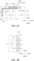
- FIG. 2A is a plan view of an inside of the heat source unit 20 of the cascade refrigeration cycle apparatus 1, the plan view schematically illustrating an arrangement of the first heat exchanger 26, the condenser 104, and the fan 40 in the heat source unit 20.
- FIG. 2B is a side view of the first heat exchanger 26, the condenser 104, and the fan 40 when viewed in a direction of arrows A-A in FIG. 2A .
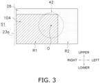
- FIG. 3 is a schematic rear view of the first heat exchanger 26 and the condenser 104 according to a first example in FIGS. 2A and 2B when viewed from a rear.
- the heat source unit 20 includes the housing 23 accommodating various devices constituting the first cycle 100, various devices constituting the second cycle 10, the fan 40, and the like. As described above, the housing 23 is installed on a rooftop of a building such as an office building in which the cascade refrigeration cycle apparatus 1 is installed, near a wall of a building, or the like.
- the heat source unit 20 here is a side-blowing heat source unit that takes in air from an opening (not illustrated) provided on a rear face or a left face of the housing 23 and blows out air having exchanged heat with the first refrigerant in the condenser 104 or air having exchanged heat with the second refrigerant in the first heat exchanger 26 from an opening provided on a front face of the housing 23.
- the housing 23 accommodates the compressor 102, the condenser 104, the cascade heat exchanger 30, the expansion mechanism 106 constituting the first cycle 100, and pipes that connect these devices and through which the first refrigerant flows.
- the housing 23 also accommodates the compressor 22, the switching mechanism 24, the first heat exchanger 26, the cascade heat exchanger 30, the expansion mechanism 28, which constitute the second cycle 10, and the pipes 21a to 21e that connect these devices and through which the second refrigerant flows.
- the housing 23 accommodates the fan 40.
- a partition plate 23a extending in a front-rear direction is disposed inside the housing 23 (in FIG. 2A , the partition plate 23a is indicated by a two-dot chain line).
- the partition plate 23a extends from near a bottom plate of the housing 23 to near a top panel of the housing 23.
- the inside of the housing 23 is divided into a machine chamber S1 and a fan chamber S2 by the partition plate 23a.
- the compressor 102, the cascade heat exchanger 30, the expansion mechanism 106, the compressor 22, the switching mechanism 24, the expansion mechanism 28, some of the pipes in the first cycle 100, and some the pipes in the second cycle 10 are mainly disposed (in FIG. 2A , devices in the machine chamber S1 is not shown).
- the condenser 104, the first heat exchanger 26, and the fan 40 are mainly disposed in the fan chamber S2.
- the condenser 104, the first heat exchanger 26, and the fan 40 disposed in the fan chamber S2 will be mainly described below.
- the flow of the refrigerant in the first heat exchanger 26 will be described below.
- the flow of the refrigerant when the cascade refrigeration cycle apparatus 1 performs the cooling operation (when the first heat exchanger 26 is a radiator) will be described below.
- an inlet 26i of the first heat exchanger 26 and an outlet 26o of the first heat exchanger 26 described later mean an inlet of the second fluid to the first heat exchanger 26 and an outlet of the second fluid from the first heat exchanger 26 in the flow of the second refrigerant in the second cycle 10 when the cascade refrigeration cycle apparatus 1 performs the cooling operation.
- the condenser 104 and the first heat exchanger 26 according to the first example illustrated in FIGS. 2A and 3 are separate heat exchangers.
- the recitation "the fact that the condenser 104 and the first heat exchanger 26 are separate heat exchangers" means that the condenser 104 and the first heat exchanger 26 do not share components such as a tube plate and a fin, unlike a fourth example in FIG. 6 described later.
- the first heat exchanger 26 has an L shape in top view.
- the first heat exchanger 26 extends from near the machine chamber S 1 to near a left rear corner of the housing 23 near an edge of the rear face of the housing 23, changes the direction near the left rear corner of the housing 23, and extends to near a left front corner of the housing 23.
- the condenser 104 has an I shape in top view.
- the condenser 104 extends from near machine chamber S 1 to an intermediate portion in a left-right direction of the fan chamber S2 near the edge of the rear face of the housing 23.
- the condenser 104 is disposed on the rear side of the first heat exchanger 26.
- the fan 40 is disposed at a center of the fan chamber S2 in the left-right direction and on the front side of the fan chamber S2. Openings (not illustrated) are formed on the rear, left, and front side walls of the housing 23 surrounding the fan chamber S2.
- Openings are formed on the rear, left, and front side walls of the housing 23 surrounding the fan chamber S2.
- the condenser 104 includes a large number of heat transfer tubes 104a aligned in an up-down direction, a large number of fins (not illustrated) attached to the heat transfer tubes 104a, and a pair of tube plates 104p to which the heat transfer tubes 104a are attached and that support the attached heat transfer tubes 104a.
- the heat transfer tubes 104a linearly extend in the left-right direction.
- the condenser 104 exemplified here only one row of heat transfer tube 104a is disposed in the airflow direction D (here, the front-rear direction).
- the condenser 104 is not limited to this example, and a plurality of rows of heat transfer tubes 26a may be aligned in the airflow direction D as in the first heat exchanger 26 described later.
- the pair of tube plates 104p of the condenser 104 are made of metal.
- the pair of tube plates 104p is disposed near the ends of the heat transfer tube 104a.
- a part of an end of the heat transfer tube 104a near the tube plate 104p disposed near the machine chamber S 1 functions as an inlet 104i (first inlet) of the condenser 104 into which the first refrigerant flows.
- Another part of the end of the heat transfer tube 104a near the tube plate 104p arranged near the machine chamber S 1 functions as an outlet 104o of the condenser 104 from which the first refrigerant flows.
- the refrigerant flowing from the inlet 104i of the condenser 104 is folded back (folded back once or a plurality of times between the left and right ends of the heat transfer tube 104a) at a U-shaped tube (not illustrated) attached to an end of the heat transfer tube 104a or a header tube (not illustrated) attached to an end of the heat transfer tube 104a, and finally flows out from the outlet 104o of the condenser 104.
- a header, a flow divider, and the like that divide the refrigerant flowing from the compressor 102 into the plurality of inlets 104i are provided near a right end of the condenser 104 where the inlet 104i is disposed.
- a header, a merging device, and the like that merge the refrigerant flowing out of the plurality of outlets 104o are provided near the right end of the condenser 104 where the outlet 104o is disposed.
- the first heat exchanger 26 includes a large number of heat transfer tubes 26a aligned in the up-down direction, a large number of fins (not illustrated) attached to the heat transfer tubes 26a, and a pair of tube plates 26p to which the heat transfer tubes 26a are attached and that support the attached heat transfer tubes 26a.
- the heat transfer tube 26a has an L shape when viewed from above.
- the heat transfer tube 26a extends from near the machine chamber S1 to near the left rear corner of the housing 23, changes the direction near the left rear corner of the housing 23, and extends forward to near the left front corner of the housing 23.
- the heat transfer tubes 26a aligned in the up-down direction are aligned in two rows in the airflow direction D generated by the fan 40. However, in the first heat exchanger 26, only one row of heat transfer tube 26a may be aligned in the airflow direction D, and three or more rows of heat transfer tubes 26a may be aligned in the airflow direction D.
- the pair of tube plates 26p of the first heat exchanger 26 are made of metal.
- the pair of tube plates 26p is disposed near the ends of the heat transfer tube 26a.
- a part of the end of the heat transfer tube 26a near the tube plate 26p disposed near the machine chamber S1 functions as an inlet 26i (second inlet) into which the second refrigerant flows.
- Another part of the end of the heat transfer tube 26a near the tube plate 26p arranged near the machine chamber S1 functions as an outlet 26o from which the second refrigerant flows.
- the refrigerant flowing from the inlet 26i of the first heat exchanger 26 is folded back (folded back once or a plurality of times between the left and right ends of the heat transfer tube 26a) at a U-shaped tube (not illustrated) attached to an end of the heat transfer tube 26a or a header tube (not illustrated) attached to an end of the heat transfer tube 26a, and finally flows out from the outlet 26o of the first heat exchanger 26.
- the two rows of heat transfer tubes 26a are aligned in the airflow direction D, and the refrigerant flowing through the heat transfer tubes 26a of one row may flow into the heat transfer tubes 26a of another row at the time of turning back.
- first heat exchanger 26 near machine chamber S1 where inlet 26i is disposed, a header, a flow divider, and the like that divide the refrigerant flowing from the first pipe 21c into the plurality of inlets 26i are provided.
- a header, a merging device, and the like that merge the refrigerant flowing out of the plurality of outlets 26o are provided near the end of the condenser 104 near the machine chamber S1 where the outlet 26o is disposed.
- a path of the refrigerant in the first heat exchanger 26 and the condenser 104 (how the refrigerant flows through the plurality of heat transfer tubes 26a of the first heat exchanger 26 and the plurality of heat transfer tubes 104a of the condenser 104) may be appropriately determined.
- the condenser 104 is disposed behind the first heat exchanger 26.
- the condenser 104 is disposed on a windward side of the first heat exchanger 26 that functions as a radiator during cooling in the airflow direction D generated by the fan 40.
- An end on one side of the condenser 104 in the direction in which the heat transfer tubes 104a extend is preferably disposed near an end on one side of the first heat exchanger 26 in the direction in which the heat transfer tubes 26a extend (an end disposed near the machine chamber S1) (see FIG. 3 ).
- an end on one side of the condenser 104 in the direction in which the heat transfer tubes 104a extend is preferably disposed near an end on one side of the first heat exchanger 26 in the direction in which the heat transfer tubes 26a extend (an end disposed near the machine chamber S1) in the front-rear direction and the left-right direction (see FIG. 3 ).
- the inlet 104i is provided at an end of the condenser 104 disposed near the machine chamber S1.
- the inlet 26i is provided at an end of the first heat exchanger 26 disposed near the machine chamber S1.
- the inlet 104i (first inlet) of the condenser 104 through which the first refrigerant flows into is disposed near the inlet 26i (second inlet) of the first heat exchanger 26 through which the second refrigerant flows into.
- the inlet 104i of the condenser 104 through which the first refrigerant flows into is disposed near the inlet 26i of the first heat exchanger 26 through which the second refrigerant flows into in the direction in which the heat transfer tubes 104a and 26a extend and in the airflow direction D.
- the outlet 104o of the condenser 104 through which the first refrigerant flows out is disposed near the outlet 26o (second inlet) of the first heat exchanger 26 through which the second refrigerant flows out.
- the position where the inlet 104i and the outlet 104o of the condenser 104 are disposed may be separated from the position where the inlet 26i and the outlet 26o of the first heat exchanger 26 are disposed (end of the first heat exchanger 26 where the inlet 26i and the outlet 26o are provided).
- the position where the inlet 104i and the outlet 104o of the condenser 104 are disposed may be located to the left of the position where the inlet 26i and the outlet 26o of the first heat exchanger 26 are disposed.
- the position where the inlet 104i and the outlet 104o of the condenser 104 and the position where the inlet 26i and the outlet 26o of the first heat exchanger 26 are disposed are preferably disposed close to each other.
- the inlet 104i of the condenser 104 and the inlet 26i of the first heat exchanger 26 are arranged close to each other, the following effects can be obtained.
- the inlet 104i (first inlet) of the condenser 104 is preferably disposed to overlap the inlet 26i (second inlet) of the first heat exchanger 26 functioning as a radiator in the airflow direction D.
- the first refrigerant flowing through the inlet 104i of the condenser 104 located the most upstream has the highest temperature. Therefore, the temperature of air that has exchanged heat with the first refrigerant flowing through the inlet 104i of the condenser 104 tends to be relatively high.
- the second refrigerant flowing through the first heat exchanger 26 functioning as a radiator exchanges heat with such relatively high-temperature air, a heat exchange efficiency tends to decrease as compared with the case of exchanging heat with relatively low-temperature air.
- the inlet 104i of the condenser 104 and the inlet 26i of the first heat exchanger 26 are preferably disposed close to each other.
- the temperature of the second refrigerant is the highest at the inlet 26i of the first heat exchanger 26 located the most upstream. Therefore, even when the temperature of the air that has exchanged heat with the first refrigerant flowing through the inlet 104i of the condenser 104 is relatively high, a decrease in the heat exchange efficiency of the first heat exchanger 26 as a radiator is easily reduced.
- the length of the condenser 104 in the left-right direction is shorter than the length of the portion of the first heat exchanger 26 extending in the left-right direction as illustrated in FIG. 2A .
- the condenser 104 at least partially overlaps the impeller (propeller) 42 when viewed in an axial direction of the axis O of the impeller 42.
- the condenser 104 is preferably disposed so as to at least partially overlap the impeller 42.
- the condenser 104 when the condenser 104 exists only for a short distance to the left side from the right end disposed near the machine chamber S 1 (when viewed in the axial direction of the axis O of the impeller 42, the condenser 104 exists only to a position not overlapping the impeller 42), it may be difficult to sufficiently secure a volume of air passing through the condenser 104.
- the condenser 104 is disposed so as to at least partially overlap the impeller 42 when facing the impeller 42 of the fan 40, and thus, a sufficient volume of air passing through the condenser 104 is easily secured.
- the height of the condenser 104 in the up-down direction is lower than the height of the first heat exchanger 26 in the up-down direction.
- the height of the condenser 104 in the up-down direction is not limited to the above, and may be the same as the height of the first heat exchanger 26 in the up-down direction.
- the condenser 104 covers only a part of the first heat exchanger 26 when viewed from upstream in the airflow direction D. In other words, in the airflow direction D, the condenser 104 overlaps only a part of the first heat exchanger 26.
- a portion hatched with diagonal lines indicates a region where the first heat exchanger 26 and the condenser 104 are disposed so as to overlap each other in rear view.
- a portion hatched with dots indicates a portion where the first heat exchanger 26 and the condenser 104 do not overlap in rear view.
- the area of the condenser 104 is smaller than the area of the first heat exchanger 26 when viewed from upstream in the airflow direction D.
- the first heat exchanger 26 has a first region R1 overlapping the condenser 104 in the airflow direction D and a second region R2 not overlapping the condenser 104 in the airflow direction D.
- the portion hatched with diagonal lines corresponds to the first region R1 of the first heat exchanger 26
- the portion hatched with dots corresponds to the second region R2 of the first heat exchanger 26.
- the condenser 104 is disposed on the windward side of the first heat exchanger 26 in the airflow direction D generated by the fan 40. Therefore, when the first heat exchanger 26 and the condenser 104 are disposed to overlap each other in the airflow direction D, in the first heat exchanger 26, the air that has exchanged heat with the first refrigerant in the condenser 104 exchanges heat with the second refrigerant. Therefore, in the portion where the first heat exchanger 26 and the condenser 104 are disposed to overlap each other in the airflow direction D, the heat exchange efficiency is deteriorated as compared with the case where the second refrigerant directly exchanges heat with the heat source air (outside air).
- the second refrigerant can directly exchange heat with the heat source air (outside air) not having exchange heat with the first refrigerant, and a decrease in heat exchange efficiency of the first heat exchanger 26 can be reduced as a whole.
- the shape, size, and arrangement of the condenser 104 are not limited to those depicted in FIGS. 2A, 2B , and 3 .
- the condenser 104 may adopt the following shape, size, and arrangement.
- FIG. 4A is a schematic rear view of the first heat exchanger 26 and the condenser 104 according to a second example when viewed from the rear face.
- FIG.4B is a plan view of the inside of the heat source unit 20 including the first exchanger 26 and the condenser 104 according to the second example, the plan view schematically illustrating an arrangement of the first heat exchanger 26, the condenser 104, and the fan 40 in the heat source unit 20.
- the first heat exchanger 26 according to the second example which is similar to the first heat exchanger 26 according to the first example, will not be described here.
- the condenser 104 according to the second example in FIG. 4A includes a large number of heat transfer tubes 104a aligned in the up-down direction, a large number of fins (not illustrated) attached to the heat transfer tubes 104a, and a pair of tube plates 104p to which the heat transfer tubes 104a are attached and that support the attached heat transfer tubes 104a.
- the condenser 104 according to the second example in FIG. 4A has an L shape when viewed from above, similarly to the heat transfer tube 26a depicted in FIG. 2A (see FIG. 4B ).
- the heat transfer tube 104a extends from near the machine chamber S1 to near the left rear corner of the housing 23, changes the direction near the left rear corner of the housing 23, and extends forward.
- the condenser 104 according to the second example in FIG. 4B may also have an I-shape in plan view, similarly to the condenser 104 according to the first example in FIG. 2A .
- the condenser 104 in FIG. 4A is lower in height than the condenser 104 depicted in FIG. 3 , and the condenser 104 is disposed upstream of the first heat exchanger 26 in the airflow direction D so as to overlap only at a lower part of the first heat exchanger 26.
- the first region R1 of the first heat exchanger 26 overlapping the condenser 104 in the airflow direction D is formed below the second region R2 of the first heat exchanger 26 not overlapping the condenser 104 in the airflow direction D.
- FIG. 5A is a schematic rear view of the first heat exchanger 26 and the condenser 104 according to a third example when viewed from the rear face.
- FIG.5B is a plan view of the inside of the heat source unit 20 including the first exchanger 26 and the condenser 104 according to the second example, the plan view schematically illustrating an arrangement of the first heat exchanger 26, the condenser 104, and the fan 40 in the heat source unit 20.
- the first heat exchanger 26 according to the third example which is similar to the first heat exchanger 26 according to the first example, will not be described here.
- the condenser 104 according to the third example in FIG. 5A includes a large number of heat transfer tubes 104a aligned in the up-down direction, a large number of fins (not illustrated) attached to the heat transfer tubes 104a, and a pair of tube plates 104p to which the heat transfer tubes 104a are attached and that support the attached heat transfer tubes 104a.
- the condenser 104 according to the third example in FIG. 5A has an L shape when viewed from above, similarly to the heat transfer tube 26a depicted in FIG. 2A (see FIG. 5B ).
- the heat transfer tube 104a extends from near the machine chamber S 1 to near the left rear corner of the housing 23, changes the direction near the left rear corner of the housing 23, and extends forward. If sufficient heat can be exchanged between the first refrigerant and the heat source air, the condenser 104 according to the third example in FIG. 5B may also have an I-shape in plan view, similarly to the condenser 104 according to the first example in FIG. 2A .
- the condenser 104 in FIG. 5A is disposed upstream of the first heat exchanger 26 in the airflow direction D so as to overlap only at an upper part of the first heat exchanger 26.
- the first region R1 of the first heat exchanger 26 overlapping the condenser 104 in the airflow direction D is formed above the second region R2 of the first heat exchanger 26 not overlapping the condenser 104 in the airflow direction D.
- the condenser 104 may be disposed upstream of the first heat exchanger 26 in the airflow direction D only in a central part of the first heat exchanger 26 in the up-down direction.
- the condenser 104 and the first heat exchanger 26 are separate heat exchangers (not sharing components such as a tube plate and a fin), but the present disclosure is not limited to these examples.
- the condenser 104 and the first heat exchanger 26 may share a fin (heat transfer fin) as follows.
- the heat transfer tube 104a (first heat transfer tube) of the condenser 104 and the heat transfer tube 26a (second heat transfer tube) of the first heat exchanger 26 may be inserted into the same fin 26b.
- FIG. 6 is a plan view of the inside of the heat source unit schematically illustrating an arrangement of the first heat exchanger 26 and the condenser 104 (integrated heat exchanger 200) sharing a fin in the fourth example.
- FIG. 7A is a schematic diagram of a tube plate 26c of the first heat exchanger 26 and a tube plate 104c of the condenser 104 according to the fourth example.
- FIG. 7B is a schematic diagram of the first heat exchanger 26 and the tube plate 26c (common tube plate) of the condenser 104 according to a modification of the fourth example.
- FIG. 8 is a schematic diagram of a fin 26b of the first heat exchanger 26 and the condenser 104 according to the fourth example.
- FIGS. 7 to 8 are drawings for description, and do not limit the number (the number of heat transfer tubes depicted by circles), the shape, and the like of the heat transfer tubes included in the integrated heat exchanger 200 in FIGS. 7 to 8 .
- the integrated heat exchanger 200 includes a large number of heat transfer tubes aligned in the up-down direction, a large number of fins 26b attached to the heat transfer tubes, and a pair of tube plates to which the heat transfer tubes are attached and that support the attached heat transfer tubes.
- the heat transfer tubes of the integrated heat exchanger 200 have an L shape when viewed from above. As illustrated in FIG. 6 , the heat transfer tube of the integrated heat exchanger 200 extends from near the machine chamber S1 to near the left rear corner of the housing 23, changes the direction near the left rear corner of the housing 23, and extends forward to near the left front corner of the housing 23.
- the heat transfer tubes aligned in the up-down direction are aligned in a plurality of rows in the airflow direction D generated by the fan 40.
- the number of rows of heat transfer tubes of the integrated heat exchanger 200 may be two, three, or five or more.
- the condenser 104 is disposed on the windward side of the first heat exchanger 26 functioning as a radiator during the cooling operation in the airflow direction D.
- the heat transfer tubes 104a are disposed upstream of the heat transfer tubes 26a, and the heat transfer tubes 26a are not disposed downstream of the heat transfer tubes 104a.
- the heat transfer tube disposed the most upstream in the airflow direction D and disposed at a lower part is used as the heat transfer tube 104a.
- the heat transfer tube of the integrated heat exchanger 200 is used as the heat transfer tube 104a may be appropriately determined.
- the fin 26b is preferably common between the condenser 104 and the first heat exchanger 26, but the tube plate is preferably not common.
- the tube plate is a metal plate-shaped member provided with a hole through which the heat transfer tube is inserted. The tube plate of the integrated heat exchanger 200 will be described with reference to FIG. 7A .
- the integrated heat exchanger 200 preferably includes the tube plate 104c (tube plate 104c through which the heat transfer tube 104a is inserted and that supports the heat transfer tube 104a), made of metal, for the condenser 104.
- the integrated heat exchanger 200 preferably includes the tube plate 26c (tube plate 26c through which the heat transfer tube 26a is inserted and which supports the heat transfer tube 26a), made of metal, for the first heat exchanger 26.
- the tube plate 104c and the tube plate 26c are separate members. The tube plate 104c and the tube plate 26c are not in contact with each other. Such a configuration can suppress heat conduction between the first refrigerant flowing through the heat transfer tube 104a and the second refrigerant flowing through the heat transfer tube 26a via the metal tube plate.
- the condenser 104 and the first heat exchanger 26 preferably have tube plates that are separate members, the condenser 104 and the first heat exchanger 26 may have the common tube plate 26c as illustrated in FIG. 7B .
- the fin 26b of the integrated heat exchanger 200 common to the condenser 104 and the first heat exchanger 26 will be described with reference to FIG. 8 .
- the fin 26b is a metal plate-shaped member provided with a hole through which the heat transfer tube is inserted.
- the fin 26b is used for improving the heat exchange efficiency of the condenser 104 and the integrated heat exchanger 200.
- the fin 26b is a plate-shaped member expanding in the up-down direction and a direction along the airflow direction D.
- the condenser 104 and the first heat exchanger 26 By sharing the fin 26b by the condenser 104 and the first heat exchanger 26 (by inserting the heat transfer tube 104a of the condenser 104 and the heat transfer tube 26a of the first heat exchanger 26 into the same fin 26b), a manufacturing process of the condenser 104 and the first heat exchanger 26 can be simplified. However, by sharing the fin 26b by the condenser 104 and the first heat exchanger 26, the first refrigerant flowing through the heat transfer tubes 104a and the second refrigerant flowing through the heat transfer tubes 26a exchange heat via the fin 26b, and there is a possibility that the efficiency of the cascade refrigeration cycle apparatus 1 is reduced.
- the fin 26b is provided with a slit 26d formed between a through portion 26bb of the heat transfer tube 104a and a through portion 26ba of the heat transfer tube 26a.
- the slit 26d extending in the up-down direction is formed in the fin 26b.
- the slit 26d having a shape other than the shape extending in the up-down direction may be formed in the fin 26b.
- a slit extending in the airflow direction D between the through portion 26bb of the heat transfer tube 104a and the through portion 26ba of the heat transfer tube 26a may be formed in the fin 26b.
- the cascade refrigeration cycle apparatus 1 includes the fan 40, the first cycle 100, the second cycle 10, and the cascade heat exchanger 30.
- the first cycle 100 the first refrigerant having a critical point of 40°C or higher circulates.
- the first cycle 100 includes the condenser 104 in which air supplied by the fan 40 and the first refrigerant exchange heat.
- carbon dioxide (CO 2 ) as the second refrigerant circulates.
- the second cycle 10 includes the first heat exchanger 26 in which the air supplied by the fan 40 and the second refrigerant exchange heat.
- the cascade heat exchanger 30 as an example of a heat exchanger in the claims, the first refrigerant and the second refrigerant exchange heat.
- the condenser 104 is disposed on the windward side of the first heat exchanger 26 in a first direction (airflow direction D) that is a direction of an airflow generated by the fan 40.
- the cascade refrigeration cycle apparatus 1 air heated by exchanging heat with CO 2 does not exchange heat with the first refrigerant flowing through the condenser 104 in the first cycle 100, but air before exchanging heat with CO 2 exchanges heat with the first refrigerant flowing through the condenser 104 in the first cycle 100. Therefore, the cascade refrigeration cycle apparatus 1 can improve the heat exchange efficiency in the condenser 104.
- CO 2 flowing through the first heat exchanger 26 in a low-side cycle at least locally exchanges heat with air having exchanged heat with the first refrigerant.
- CO 2 is a refrigerant in which the heat exchange efficiency deteriorates under the condition of high outside air (see the thermal cycle when outside air temperature changes to 20°C, 30°C, and 40°C).
- the efficiency of the CO 2 refrigerant is poor under the condition of high outside air by nature.
- the cascade refrigeration cycle apparatus 1 can improve the efficiency while suppressing an increase in installation space and an increase in necessary equipment.
- the critical point of the first refrigerant is preferably 50°C or higher.
- the cascade refrigeration cycle apparatus 1 with efficiency can be achieved even in an environment where the temperature of the air that exchanges heat with the condenser 104 is high.
- the first heat exchanger 26 has the first region R1 overlapping the condenser 104 in the airflow direction D and the second region R2 not overlapping the condenser 104 in the airflow direction D.
- the first heat exchanger 26 has the second region R2 not overlapping the condenser 104 in the airflow direction D. Therefore, even the first heat exchanger 26 installed on a leeward side of the condenser 104 can achieve relatively high heat exchange efficiency in the region not overlapping the condenser 104.
- the presence of the second region R2 is preferable but not essential, and the first heat exchanger 26 of the cascade refrigeration cycle apparatus 1 may have only the first region R1.
- the condenser 104 has the inlet 104i as an example of a first inlet through which the first refrigerant flows into.
- the first heat exchanger 26 has the inlet 26i as an example of a second inlet through which the second refrigerant flows into.
- the inlet 26i is disposed near the inlet 104i.
- the first refrigerant flowing through the inlet 104i of the condenser 104 located the most upstream has the highest temperature. Therefore, the temperature of air that has exchanged heat with the first refrigerant flowing through the inlet 104i of the condenser 104 tends to be relatively high.
- the second refrigerant flowing through the first heat exchanger 26 functioning as a radiator exchanges heat with such relatively high-temperature air, a heat exchange efficiency tends to decrease as compared with the case of exchanging heat with relatively low-temperature air.
- the inlet 104i of the condenser 104 and the inlet 26i of the first heat exchanger 26 are preferably disposed close to each other.
- the temperature of the second refrigerant is the highest at the inlet 26i of the first heat exchanger 26 located the most upstream. Therefore, even when the temperature of the air that has exchanged heat with the first refrigerant flowing through the inlet 104i of the condenser 104 is relatively high, a decrease in the heat exchange efficiency of the first heat exchanger 26 as a radiator is easily reduced.
- the inlet 104i of the condenser 104 and the inlet 26i of the first heat exchanger 26 are disposed close to each other, the pipes in the first cycle 100 and the second cycle 10 can be easily installed.
- the fan 40 includes the impeller 42.
- the condenser 104 at least partially overlaps the impeller 42 when viewed in the axial direction of the axis O of the impeller 42.
- the condenser 104 includes the heat transfer tube 104a as an example of a first heat transfer tube
- the first heat exchanger 26 includes the heat transfer tube 26a as an example of a second heat transfer tube.
- the heat transfer tube 104a and the heat transfer tube 26a are inserted into the fin 26b being common to each other.
- the fin 26b is provided with the slit 26d formed between the through portion 26bb of the heat transfer tube 104a and the through portion 26ba of the heat transfer tube 26a.
- the condenser 104 includes the tube plate 104p made of metal as an example of a first tube plate.
- the heat transfer tube 104a is inserted through the tube plate 104p, and the tube plate 104p supports the heat transfer tube 104a.
- the first heat exchanger 26 includes the tube plate 26p made of metal as an example of a second tube plate.
- the heat transfer tube 26a is inserted through the tube plate 26p, and the tube plate 26p supports the heat transfer tube 26a.
- the tube plate 104p and the tube plate 26p are separate members.
- the condenser 104 includes the tube plate 104c made of metal as an example of a first tube plate.
- the heat transfer tube 104a is inserted through the tube plate 104c, and the tube plate 104c supports the heat transfer tube 104a.
- the first heat exchanger 26 includes the tube plate 26c made of metal as an example of a second tube plate.
- the heat transfer tube 26a is inserted through the tube plate 26c, and the tube plate 26c supports the heat transfer tube 26a.
- the tube plate 104c and the tube plate 26c are separate members.
- the heat source unit 20 here is a side-blowing heat exchange unit that takes in air from an opening provided on the rear face and the left face of the housing 23 and blows out air having exchanged heat with the first refrigerant in the condenser 104 or air having exchanged heat with the second refrigerant in the first heat exchanger 26 from an opening provided on the front face of the housing 23.
- the type of the heat source unit 20 is not limited to the side-blowing type.
- the heat source unit 20 may be a top-blowing heat source unit.
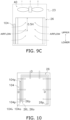
- FIG. 9A is a schematic side view of the inside of the heat source unit 20 schematically illustrating an example of the arrangement of the first heat exchanger 26, the condenser 104, and the fan 40 of the heat source unit 20 according to Modification A
- FIG. 9B is a schematic side view of the inside of the heat source unit 20 schematically illustrating another example of arrangement of the first heat exchanger 26, the condenser 104, and the fan 40 of the heat source unit 20 according to Modification A
- FIG. 9C is a schematic side view of the inside of the heat source unit 20, illustrating still another example of the arrangement of the first heat exchanger 26, the condenser 104, and the fan 40 of the heat source unit 20 according to Modification A.
- the fan 40 is disposed above the first heat exchanger 26 and the condenser 104.
- the heat transfer tubes 26a and 104a extending in a horizontal direction are aligned in the up-down direction.
- the heat transfer tubes 26a and 104a extending in a horizontal direction are aligned in the up-down direction.
- the fan 40 when the fan 40 is operated in the heat source unit 20, air is taken in from an opening provided on a side surface of the housing 23 and passes through the condenser 104 and the first heat exchanger 26.
- the air having exchanged heat with the first refrigerant in the condenser 104 and the air having exchanged heat with the second refrigerant in the first heat exchanger 26 is blown upward from an opening provided in an upper surface of the housing 23.
- the condenser 104 is preferably disposed at a position at least partially overlapping the upper part of the first heat exchanger 26 in the airflow direction D.
- the upper part of the first heat exchanger 26 means a part from an upper end to 0.5 H below the upper end (that is, an upper half) of the first heat exchanger 26, with respect to a total height H from the upper end to a lower end of the first heat exchanger 26.
- the airflow direction D here means a direction being generally horizontal and a direction from the outside to the inside of the housing 23 (for example, a direction from the front to the rear on the front face of the housing 23).
- the condenser 104 is disposed so as to overlap the first heat exchanger 26 at a height position excluding a part of the lower part of the first heat exchanger 26 in the airflow direction D.
- a wind speed increases at the upper part close to the fan 40. Therefore, when the arrangement as illustrated in FIG. 9A is adopted in the condenser 104, even if the length of the condenser 104 in the height direction is reduced as compared with the first heat exchanger 26, a sufficient amount of air is easily supplied to the condenser 104.
- the condenser 104 may be disposed so as to overlap the entire first heat exchanger 26 in the airflow direction D.
- the condenser 104 may be disposed so as to overlap the first heat exchanger 26 at a height position excluding a part of the upper part of the first heat exchanger 26 in the airflow direction D.
- the condenser 104 is preferably disposed at a position at least partially overlapping the upper part of the first heat exchanger 26 in the airflow direction D.
- the condenser 104 may be disposed at a part of a height position at which the first heat exchanger 26 is disposed, the height position being different from the position illustrated in FIGS. 9A and 9C .
- the first heat exchanger 26 has a C shape when viewed in top view.
- the shape of the first heat exchanger 26 of the heat source unit 20 according to Modification A is not limited to a C shape in top view.
- the shape of the first heat exchanger 26 of the heat source unit 20 according to Modification A may be a quadrangular shape in top view.
- the condenser 104 is disposed at a position corresponding to a part of the first heat exchanger 26 in top view, on the windward side of the first heat exchanger 26 functioning as a radiator during the cooling operation in the airflow direction D generated by the fan 40.
- the present disclosure is not limited to this arrangement, and the condenser 104 may be disposed at a position corresponding to the entire first heat exchanger 26 in top view, on the windward side of the first heat exchanger 26 functioning as a radiator during the cooling operation in the airflow direction D generated by the fan 40. It should be noted that how much the condenser 104 overlaps the first heat exchanger 26 in top view may be appropriately determined as necessary.
- the characteristics of the first heat exchanger 26 and the condenser 104 according to the first example of the above embodiment may be applied, or the characteristics of the first heat exchanger 26 and the condenser 104 according to the second to fourth examples of the above embodiment may be applied.
- the fan 40 blows out air having passed through the condenser 104 and the first heat exchanger 26 upward.
- the condenser 104 is disposed at a position at least partially overlapping the upper part of the first heat exchanger 26.
- the wind speed increases at the upper part close to the fan 40.
- the condenser 104 is disposed at a position at least partially overlapping an upper part of the first heat exchanger 26. Accordingly, heat of the first refrigerant can be efficiently exchanged in the condenser 104.
- Patent Literature 1 WO 2014/181399 A
Landscapes
- Engineering & Computer Science (AREA)
- Physics & Mathematics (AREA)
- Thermal Sciences (AREA)
- Mechanical Engineering (AREA)
- General Engineering & Computer Science (AREA)
- Geometry (AREA)
- Chemical & Material Sciences (AREA)
- Chemical Kinetics & Catalysis (AREA)
- Other Air-Conditioning Systems (AREA)
Abstract
Description
- The present disclosure relates to a cascade refrigeration cycle apparatus.
- From the viewpoint of environmental conservation, a technique using carbon dioxide (CO2) having a small global warming potential as a refrigerant has attracted attention.
- In a case where CO2 is used as a refrigerant in a refrigeration cycle apparatus and heat is exchanged between heat source air and CO2 in a radiator, due to characteristics of CO2, when a temperature of the heat source air is high, the refrigerant does not change in phase in the radiator, an enthalpy difference due to the heat exchange decreases, and efficiency deteriorates.
- Therefore, for example, as in Patent Literature 1 (
WO 2014/181399 A ), there is known a cascade refrigeration cycle apparatus in which a cycle using CO2 as a refrigerant and a supercooling cycle for exchanging heat with CO2 are combined to expand a supercooling region of a cycle using CO2 and improve efficiency. - However, in the cascade refrigeration cycle apparatus of Patent Literature 1 (
WO 2014/181399 A ), the condenser of the subcooling cycle is disposed on a leeward side of the radiator of the cycle using CO2, and there is room for improvement from the viewpoint of efficiency. - A cascade refrigeration cycle apparatus according to a first aspect comprises a fan, a first cycle, a second cycle, and a heat exchanger. In the first cycle, a first refrigerant having a critical point of 40°C or higher circulates. The first cycle includes a condenser in which air supplied by the fan and the first refrigerant exchange heat. In the second cycle, carbon dioxide as a second refrigerant circulates. The second cycle includes a radiator in which air supplied by the fan and the second refrigerant exchange heat. In the heat exchanger, the first refrigerant and the second refrigerant exchange heat. The condenser is disposed on a windward side of the radiator in a first direction that is a direction of an airflow generated by the fan.
- In the cascade refrigeration cycle apparatus according to the first aspect, air heated by exchanging heat with CO2 does not exchange heat with the first refrigerant flowing through the condenser in the first cycle, but air before exchanging heat with CO2 exchanges heat with the first refrigerant flowing through the condenser in the first cycle. Therefore, the cascade refrigeration cycle apparatus according to the first aspect can improve a heat exchange efficiency in the condenser.
- Meanwhile, in the cascade refrigeration cycle apparatus according to the first aspect, CO2 flowing through the radiator in a low-side cycle at least locally exchanges heat with air having exchanged heat with the first refrigerant. However, CO2 is a refrigerant having a relatively poor heat exchange efficiency. Therefore, even if the air heated by exchanging heat with the first refrigerant is supplied to the radiator, the influence on the overall efficiency is smaller than when the air heated by exchanging heat with CO2 exchanges heat with the first refrigerant flowing through the condenser in the first cycle.
- A cascade refrigeration cycle apparatus according to a second aspect is the cascade refrigeration cycle apparatus according to the first aspect, in which the radiator includes a first region overlapping the condenser in the first direction and a second region not overlapping the condenser in the first direction.
- In the cascade refrigeration cycle apparatus according to the second aspect, the radiator has a region not overlapping the condenser in a direction of airflow. Therefore, even the radiator installed on a leeward side of the condenser can achieve a relatively high heat exchange efficiency in the region not overlapping the condenser.
- A cascade refrigeration cycle apparatus according to a third aspect is the cascade refrigeration cycle apparatus according to the first or second aspect, in which the condenser has a first inlet through which the first refrigerant flows into. The radiator has a second inlet through which the second refrigerant flows into. The second inlet is disposed near the first inlet.
- Among the first refrigerants flowing in the condenser, the first refrigerant flowing through the first inlet of the condenser located the most upstream has the highest temperature. Therefore, the temperature of air that has exchanged heat with the first refrigerant flowing through the first inlet of the condenser tends to be relatively high. When the second refrigerant flowing through the radiator exchanges heat with such relatively high-temperature air, the heat exchange efficiency tends to decrease as compared with the case of exchanging heat with relatively low-temperature air.
- In the cascade refrigeration cycle apparatus according to the third aspect, the inlet of the radiator and the inlet of the condenser are disposed close to each other in order to reduce such a decrease in heat exchange efficiency. Among the second refrigerants flowing in the radiator, the temperature of the second refrigerant is the highest at the second inlet of the radiator located the most upstream. Therefore, even when the temperature of the air that has exchanged heat with the first refrigerant flowing near the first inlet of the condenser is relatively high, a decrease in the heat exchange efficiency of the radiator is easily reduced.
- A cascade refrigeration cycle apparatus according to a fourth aspect is the cascade refrigeration cycle apparatus according to any of the first to third aspects, in which the fan includes an impeller. The condenser at least partially overlaps the impeller when viewed in an axial direction of the impeller.
- In the cascade refrigeration cycle apparatus according to the fourth aspect, since a sufficient volume of air passing through the condenser is easily secured, it is easy to sufficiently radiate heat from the first refrigerant in the condenser.
- A cascade refrigeration cycle apparatus according to a fifth aspect is the cascade refrigeration cycle apparatus according to any of the first to fourth aspects, in which the condenser includes a first heat transfer tube. The radiator includes a second heat transfer tube. The first heat transfer tube and the second heat transfer tube are inserted into a fin being common to each other. The fin is provided with a slit formed between a through portion of the first heat transfer tube and a through portion of the second heat transfer tube.
- In the cascade refrigeration cycle apparatus according to the fifth aspect, even when the condenser and the radiator use the common fin, heat conduction between the first refrigerant and the second refrigerant via the fin is easily reduced.
- A cascade refrigeration cycle apparatus according to a sixth aspect is the cascade refrigeration cycle apparatus the fifth aspect, in which the condenser includes a first tube plate made of metal. The first heat transfer tube is inserted through the first tube plate, and the first tube plate supports the first heat transfer tube. The radiator further includes a second tube plate made of metal. The second heat transfer tube is inserted through the second tube plate, and the second tube plate supports the second heat transfer tube. The first tube plate and the second tube plate are separate members.
- In the cascade refrigeration cycle apparatus according to the sixth aspect, heat conduction between the condenser and the radiator is easily reduced.
- A cascade refrigeration cycle apparatus according to a seventh aspect is the cascade refrigeration cycle apparatus according to any of the first, second, third, fifth, or sixth aspect, in which the fan is disposed above the condenser and the radiator. In the fan, the condenser is disposed at a position at least partially overlapping an upper part of the radiator.
- In a top-blowing heat source unit, a wind speed increases at an upper part close to the fan. In a cascade refrigeration cycle apparatus according to a seventh aspect, the condenser is disposed at a position at least partially overlapping the upper part of the radiator. Accordingly, heat of the first refrigerant can be efficiently exchanged in the condenser.
-
-
FIG. 1 is a schematic configuration diagram of a cascade refrigeration cycle apparatus according to an embodiment of the present disclosure. -
FIG. 2A is a plan view of an inside of a heat source unit of the cascade refrigeration cycle apparatus inFIG. 1 , the plan view schematically illustrating an arrangement of a first heat exchanger, a condenser, and a fan in the heat source unit. -
FIG. 2B is a side view of the first heat exchanger, the condenser, and the fan when viewed in a direction of arrows A-A inFIG. 2A . -
FIG. 3 is a schematic rear view of the first heat exchanger and the condenser according to a first example inFIGS. 2A and 2B when viewed from a rear. -
FIG. 4A is a schematic rear view of the first heat exchanger and the condenser according to a second example when viewed from the rear. -
FIG. 4B is a plan view of the inside of the heat source unit including the first exchanger and the condenser according to a second example, the plan view schematically illustrating an arrangement of the first heat exchanger, the condenser, and the fan in the heat source unit. -
FIG. 5A is a schematic rear view of the first heat exchanger and the condenser according to a third example when viewed from the rear. -
FIG.5B is a plan view of the inside of the heat source unit including the first exchanger and the condenser according to the second example, the plan view schematically illustrating an arrangement of the first heat exchanger, the condenser, and the fan in the heat source unit. -
FIG. 6 is a plan view of the inside of the heat source unit, schematically illustrating an arrangement of the first heat exchanger and the condenser (integrated heat exchanger) sharing a fin in a fourth example. -
FIG. 7A is a schematic diagram of tube plates of the first heat exchanger and the condenser according to the fourth example. -
FIG. 7B is a schematic diagram of a tube plate according to a modification of the first heat exchanger and the condenser according to the fourth embodiment. -
FIG. 8 is a schematic diagram of a fin of the first heat exchanger and the condenser according to the fourth example. -
FIG. 9A is a schematic side view of the inside of the heat source unit according to Modification A, illustrating an example of the arrangement of the first heat exchanger, the condenser, and the fan. -
FIG. 9B is a schematic side view of the inside of the heat source unit according to Modification A, illustrating another example of the arrangement of the first heat exchanger, the condenser, and the fan. -
FIG. 9C is a schematic side view of the inside of the heat source unit according to Modification A, illustrating still another example of the arrangement of the first heat exchanger, the condenser, and the fan. -
FIG. 10 is a schematic plan view of the inside of the heat source unit according to Modification A, the plan view schematically illustrating the arrangement of the first heat exchanger and the condenser. -
FIG. 11 is a schematic Mollier diagram for describing performance when a second cycle is used alone and performance when a first cycle and the second cycle are used in combination. -
FIG. 12 is a Mollier diagram for describing an influence of an outside air temperature on efficiency of the second cycle. - A cascade refrigeration cycle apparatus according to an embodiment of the present disclosure will be described hereinafter with reference to the drawings.
- An outline of a cascade
refrigeration cycle apparatus 1 of the present disclosure will be described hereinafter with reference toFIG. 1. FIG. 1 is a schematic configuration diagram of the cascaderefrigeration cycle apparatus 1. - The cascade
refrigeration cycle apparatus 1 is an apparatus that performs vapor compression refrigeration cycle operation to cool or heat a temperature adjustment target. In the present embodiment, the cascaderefrigeration cycle apparatus 1 cools or heats air in a room of an office building or the like as a temperature adjustment target to perform cooling or heating of the room of the office building or the like. - In the present embodiment, the temperature adjustment target of the cascade
refrigeration cycle apparatus 1 is air. Alternatively, the cascade refrigeration cycle apparatus of the present disclosure may be a device that cools or heats water, a heat medium, or the like that is the temperature adjustment target. In the present embodiment, the cascaderefrigeration cycle apparatus 1 cools and heats a room in an office building or the like, but the cascade refrigeration cycle apparatus may be an apparatus dedicated to cooling. - As illustrated in
FIG. 1 , the cascaderefrigeration cycle apparatus 1 mainly includes a vapor compressionfirst cycle 100, a vapor compressionsecond cycle 10, afan 40, and acontrol device 90. - The
first cycle 100 is a refrigerant circuit in which a first refrigerant having a higher critical point than a second refrigerant used in thesecond cycle 10 circulates. - The first refrigerant is a refrigerant having a critical point of 40°C or higher. The first refrigerant is preferably a refrigerant having a critical point of 50°C or higher. The first refrigerant preferably has a relatively low global warming potential. Although the type of the refrigerant is not limited, the first refrigerant is, for example, any single refrigerant of R290 (critical point 370°C), R1234yf (critical point 95°C), R1234ze (critical point 154°C), or R32 (critical point 72°C), or a mixed refrigerant including the above refrigerants.
- The
second cycle 10 is a refrigerant circuit through which a refrigerant including carbon dioxide (CO2) circulates as the second refrigerant. The critical point of CO2 is 31.1°C. In the present embodiment, the refrigerant circulating in thesecond cycle 10 is a single refrigerant of CO2. - The
first cycle 100 and thesecond cycle 10 are thermally connected via acascade heat exchanger 30. In thecascade heat exchanger 30, the first refrigerant circulating in thefirst cycle 100 and the second refrigerant circulating in thesecond cycle 10 exchange heat. - The cascade
refrigeration cycle apparatus 1 includes thefirst cycle 100 in addition to thesecond cycle 10 for the following reasons. - At present, from the viewpoint of environmental conservation, use of CO2 as a refrigerant attracts attention. CO2 has an excellent characteristic of having a small global warming potential but has a characteristic of having a low critical point. Therefore, in a case where only the second cycle using CO2 as the second refrigerant is used in the refrigeration cycle apparatus, if a cooling operation is performed by using the heat exchanger on a heat source side as a radiator under a condition where the temperature of heat source air is high (a condition where the temperature of the heat source air exceeds the critical point of CO2), the CO2 does not change in phase, and thus the cycle becomes a cycle as indicated by a broken line in
FIG. 11 . In such a cycle, since an enthalpy difference due to heat exchange is small, the obtained cooling capacity becomes relatively small as indicated by a double-headed arrow of a broken line inFIG. 11 , and the efficiency is deteriorated. - On the other hand, in the cascade
refrigeration cycle apparatus 1 of the present disclosure, the first cycle having a relatively high critical point is used for subcooling the second refrigerant in addition to the second cycle using CO2 as the second refrigerant. Therefore, the cycle can be improved as indicated by a one-dot chain line in the Mollier diagram ofFIG. 11 , and the obtained cooling capacity can be expanded as indicated by a double-headed arrow of a one-dot chain line inFIG. 11 . - The
fan 40 is a device that generates an airflow in order to supply air as a heat source (heat source air) to acondenser 104 in thefirst cycle 100 and afirst heat exchanger 26 in thesecond cycle 10. - As illustrated in
FIG. 1 , the cascaderefrigeration cycle apparatus 1 is divided into aheat source unit 20 and autilization unit 50. Theheat source unit 20 and theutilization unit 50 are connected viaconnection pipes second cycle 10. - The
heat source unit 20 includes ahousing 23. Thehousing 23 accommodates various devices constituting thefirst cycle 100, some of various devices constituting thesecond cycle 10, thefan 40, and the like. Theheat source unit 20 is installed on, but not limited to, a rooftop of a building such as an office building in which the cascaderefrigeration cycle apparatus 1 is installed, near a wall of a building, or the like. - The
utilization unit 50 includes ahousing 51. Thehousing 51 accommodates asecond heat exchanger 52 of thesecond cycle 10, a fan (not illustrated) that supplies air to thesecond heat exchanger 52, and the like. Theutilization unit 50 is installed, for example, in an air conditioning target space or near the air conditioning target space (for example, a ceiling space or the like of the air conditioning target space). Although only oneutilization unit 50 having thesecond heat exchanger 52 is depicted in the example ofFIG. 1 , the cascaderefrigeration cycle apparatus 1 may include a plurality ofutilization units 50 having thesecond heat exchangers 52 connected in parallel to each other. - The
control device 90 is electrically connected to various devices constituting thesecond cycle 10, various devices constituting thefirst cycle 100, and thefan 40 and controls operations of the devices electrically connected to thecontrol device 90. - The
first cycle 100, thesecond cycle 10, thefan 40, thecontrol device 90, and theheat source unit 20 will be described in detail. - In the first cycle (first refrigerant circuit) 100, the first refrigerant circulates. The
first cycle 100 is mainly used for subcooling the second refrigerant flowing in the second cycle during the cooling operation. - The
first cycle 100 mainly includes acompressor 102, thecondenser 104, anexpansion mechanism 106, and thecascade heat exchanger 30 which are connected by pipes. In thefirst cycle 100, the first refrigerant discharged from thecompressor 102 flows through thecondenser 104, theexpansion mechanism 106, and thecascade heat exchanger 30 in this order, and returns to a suction side of thecompressor 102. - The
compressor 102 compresses the first refrigerant. For example, thecompressor 102 is a variable operating capacity compressor including an inverter-controlled motor. Alternatively, thecompressor 102 may be a compressor having a constant operating capacity. Thecompressor 102 is, for example, a scroll compressor or a rotary compressor. However, the type of thecompressor 102 is not limited to the above examples, and may be appropriately selected. - In the
condenser 104, the air (heat source air) supplied by thefan 40 and the first refrigerant exchange heat. In thecondenser 104, the first refrigerant obtains cold energy from the heat source air. Thecondenser 104 is, for example, a fin-and-tube heat exchanger having a large number of heat transfer tubes and fins. - The
expansion mechanism 106 decompresses the first refrigerant. Theexpansion mechanism 106 is, for example, an electronic expansion valve having a variable opening degree. However, theexpansion mechanism 106 is not limited to this example, and may be an automatic temperature expansion valve having a temperature sensitive cylinder or a capillary tube. - The
cascade heat exchanger 30 causes the first refrigerant and the second refrigerant to exchange heat with each other without mixing the first refrigerant and the second refrigerant. Thecascade heat exchanger 30 is, for example, a plate heat exchanger. Thecascade heat exchanger 30 includes afirst flow path 32 constituting a part of thefirst cycle 100 and asecond flow path 34 constituting a part of thesecond cycle 10. In thecascade heat exchanger 30, the first refrigerant flowing throughfirst flow path 32 and a second fluid flowing throughsecond flow path 34 exchange heat, and the second fluid is cooled by the first fluid. One end of thefirst flow path 32 is connected to theexpansion mechanism 106 via a refrigerant pipe, and the other end is connected to the suction side of thecompressor 102 via a refrigerant pipe. - In the second cycle (second refrigerant circuit) 10, the second refrigerant circulates. The second refrigerant circulating in the
second cycle 10 is used for cooling and heating the air in a space as the temperature adjustment target. - The
second cycle 10 mainly includes acompressor 22, aswitching mechanism 24, thefirst heat exchanger 26, thecascade heat exchanger 30, anexpansion mechanism 28, and thesecond heat exchanger 52. - The
compressor 22 compresses the second refrigerant. For example, thecompressor 22 is a variable operating capacity compressor including an inverter-controlled motor. Alternatively, thecompressor 22 may be a compressor having a constant operating capacity. Thecompressor 22 is, for example, a scroll compressor or a rotary compressor. However, the type of thecompressor 22 is not limited to the above examples, and may be appropriately selected. - The
switching mechanism 24 is a mechanism that switches a state of thesecond cycle 10 between a first state and a second state. When thesecond cycle 10 is in the first state (see the solid line of theswitching mechanism 24 inFIG. 1 ), thefirst heat exchanger 26 functions as a radiator for the second refrigerant, and thesecond heat exchanger 52 functions as an evaporator for the second refrigerant. When thesecond cycle 10 is in the second state (see the broken line of theswitching mechanism 24 inFIG. 1 ), thefirst heat exchanger 26 functions as an evaporator for the second refrigerant, and thesecond heat exchanger 52 functions as a radiator for the second refrigerant. - The
switching mechanism 24 is, for example, a four-way switching valve. When the state of thesecond cycle 10 is set to the first state, theswitching mechanism 24 connects adischarge pipe 21b and a first pipe 21c, and connects a suction pipe 21a and athird pipe 21e. When the state of thesecond cycle 10 is set to the second state, theswitching mechanism 24 connects thedischarge pipe 21b and thethird pipe 21e, and connects the suction pipe 21a and the first pipe 21c. Here, thedischarge pipe 21b is a pipe that connects a discharge side of thecompressor 22 and theswitching mechanism 24. The first pipe 21c is a pipe that connects theswitching mechanism 24 and thefirst heat exchanger 26. Here, the suction pipe 21a is a pipe that connects the suction side of thecompressor 22 and theswitching mechanism 24.Third pipe 21e is a pipe that connects theswitching mechanism 24 and theconnection pipe 14. - In the
first heat exchanger 26, the air (heat source air) supplied by thefan 40 and the second refrigerant exchange heat. When the state of thesecond cycle 10 is the first state, thefirst heat exchanger 26 functions as a radiator, and the second refrigerant obtains cold energy from the heat source air in thefirst heat exchanger 26. When the state of thesecond cycle 10 is the second state, thefirst heat exchanger 26 functions as an evaporator, and the second refrigerant obtains thermal energy from the heat source air in thefirst heat exchanger 26. Thefirst heat exchanger 26 is, for example, a fin-and-tube heat exchanger having a large number of heat transfer tubes and fins. - As described above, the
cascade heat exchanger 30 is a heat exchanger that causes the first refrigerant and the second refrigerant to exchange heat without mixing with each other, and thesecond flow path 34 of thecascade heat exchanger 30 constitutes a part of thesecond cycle 10. Thecascade heat exchanger 30 is disposed in thesecond pipe 21d. Thesecond pipe 21d is a pipe that connects thefirst heat exchanger 26 and theconnection pipe 12 in thesecond cycle 10. - The
expansion mechanism 28 decompresses the second refrigerant. Theexpansion mechanism 28 is disposed on thesecond pipe 21d between thecascade heat exchanger 30 and a connecting portion between thesecond pipe 21d and theconnection pipe 12. Theexpansion mechanism 28 is, for example, an electronic expansion valve having a variable opening degree. However, theexpansion mechanism 28 is not limited to this example, and may be an automatic temperature expansion valve having a temperature sensitive cylinder or a capillary tube. - In the
second heat exchanger 52, the second refrigerant and air in the air conditioning target space exchange heat. Thesecond heat exchanger 52 is accommodated in thehousing 51. The air in the air conditioning target space is supplied to thesecond heat exchanger 52 by a fan (not illustrated) disposed in thehousing 51. In thesecond heat exchanger 52, the air in the air conditioning target space supplied by the fan and the second refrigerant exchange heat. When the state of thesecond cycle 10 is the first state, thesecond heat exchanger 52 functions as an evaporator, and the air in the air conditioning target space is cooled by the second refrigerant in thesecond heat exchanger 52. When the state of thesecond cycle 10 is the second state, thesecond heat exchanger 52 functions as a radiator, and the air in the air conditioning target space is heated by the second refrigerant in thesecond heat exchanger 52. Thesecond heat exchanger 52 is, for example, a fin-and-tube heat exchanger having a large number of heat transfer tubes and fins. - The
fan 40 is accommodated in thehousing 23 of theheat source unit 20. Thefan 40 rotates animpeller 42 about an axis O by a motor (not illustrated) to supply the heat source air to thecondenser 104 in thefirst cycle 100 and thefirst heat exchanger 26 in thesecond cycle 10 accommodated in thehousing 23 of theheat source unit 20. Thus, heat exchange between the first refrigerant and the second refrigerant and the heat source air are promoted. Thefan 40 is, for example, an axial flow fan, although the type is not limited. In the present embodiment, in particular, thefan 40 is, for example, a propeller fan. - The
control device 90 is a device that controls the operation of the cascaderefrigeration cycle apparatus 1. - The
control device 90 is electrically connected to thecompressor 102 and theexpansion mechanism 106 in thefirst cycle 100, thecompressor 22, theswitching mechanism 24 and theexpansion mechanism 28 in thesecond cycle 10, and the fan 40 (see the broken lines inFIG. 1 ). Thecontrol device 90 controls the operation of the cascaderefrigeration cycle apparatus 1 by controlling the operation of these electrically connected devices. - In the present embodiment, an electric circuit and a control board (not illustrated) mounted on the
heat source unit 20 and an electric circuit and a control board (not illustrated) mounted on theutilization unit 50 are communicably connected to each other, and function as thecontrol device 90 in cooperation with each other.FIG. 1 illustrates thecontrol device 90, for convenience, at a position away from theheat source unit 20, theutilization unit 50, and the like. - In the present embodiment, the
control device 90 includes an arithmetic and control unit and a storage. As the arithmetic and control unit, a processor such as a CPU can be used. The arithmetic and control unit reads a program stored in the storage, and controls the operation of the cascaderefrigeration cycle apparatus 1 in accordance with this program. - Specifically, when causing the cascade
refrigeration cycle apparatus 1 to perform a heating operation, thecontrol device 90 controls the operation of theswitching mechanism 24 to set the state of thesecond cycle 10 to the second state and operate thecompressor 22. Thecontrol device 90 controls an operating capacity of the motor of thecompressor 22 on the basis of a measurement result of a sensor (a sensor that measures a temperature and a pressure of the second refrigerant at an appropriate location in thesecond cycle 10, or a sensor that measures a temperature of the heat source air, the sensor is referred to as a first sensor hereinafter), not illustrated, disposed at an appropriate location. Thecontrol device 90 operates the motors of thefan 40 and a fan of theutilization unit 50 at a predetermined number of rotations. Furthermore, thecontrol device 90 controls the opening degree of the electronic expansion valve as theexpansion mechanism 28 on the basis of the measurement result of the first sensor. - When causing the cascade
refrigeration cycle apparatus 1 to perform the cooling operation, thecontrol device 90 controls the operation of theswitching mechanism 24 to set the state of thesecond cycle 10 to the first state and operate thecompressor 22. Thecontrol device 90 controls the operating capacity of the motor of thecompressor 22 on the basis of the measurement result of the first sensor. Thecontrol device 90 operates the motors of thefan 40 and a fan of theutilization unit 50 at a predetermined number of rotations. Furthermore, thecontrol device 90 controls the opening degree of the electronic expansion valve as theexpansion mechanism 28 on the basis of the measurement result of the first sensor. - Furthermore, the
control device 90 operates thecompressor 102 when causing the cascaderefrigeration cycle apparatus 1 to perform the cooling operation. Thecontrol device 90 may operate thecompressor 102 whenever causing the cascaderefrigeration cycle apparatus 1 to perform the cooling operation. Alternatively, thecontrol device 90 may operate thecompressor 102, for example, when the temperature of the heat source air (outside air) is higher than a predetermined temperature. Thecontrol device 90 controls an operating capacity of the motor of thecompressor 102 on the basis of a measurement result of a sensor (a sensor that measures a temperature and a pressure of the first refrigerant at an appropriate location in thefirst cycle 100, or a sensor that measures a temperature of the heat source air, the sensor is referred to as a second sensor hereinafter), not illustrated, disposed at an appropriate location. Thecontrol device 90 controls the opening degree of the electronic expansion valve as theexpansion mechanism 106 on the basis of the measurement result of the second sensor. - The
heat source unit 20 will be described mainly with reference toFIGS. 2A, 2B , and3 in addition toFIG. 1 .FIG. 2A is a plan view of an inside of theheat source unit 20 of the cascaderefrigeration cycle apparatus 1, the plan view schematically illustrating an arrangement of thefirst heat exchanger 26, thecondenser 104, and thefan 40 in theheat source unit 20.FIG. 2B is a side view of thefirst heat exchanger 26, thecondenser 104, and thefan 40 when viewed in a direction of arrows A-A inFIG. 2A .FIG. 3 is a schematic rear view of thefirst heat exchanger 26 and thecondenser 104 according to a first example inFIGS. 2A and 2B when viewed from a rear. - In the following description, expressions indicating directions such as "upper", "lower", "front (front face)", "rear (rear face)" "left", and "right" are used for convenience in order to represent directions and positions. Unless otherwise specified, expressions such as "upper", "lower", "front (front face)", "rear (rear face)", "left", and "right" follow directions of arrows in the drawings. Note that, unless otherwise specified, these expressions are not intended to limit the disclosure of the present application.
- The
heat source unit 20 includes thehousing 23 accommodating various devices constituting thefirst cycle 100, various devices constituting thesecond cycle 10, thefan 40, and the like. As described above, thehousing 23 is installed on a rooftop of a building such as an office building in which the cascaderefrigeration cycle apparatus 1 is installed, near a wall of a building, or the like. - The
heat source unit 20 here is a side-blowing heat source unit that takes in air from an opening (not illustrated) provided on a rear face or a left face of thehousing 23 and blows out air having exchanged heat with the first refrigerant in thecondenser 104 or air having exchanged heat with the second refrigerant in thefirst heat exchanger 26 from an opening provided on a front face of thehousing 23. - The
housing 23 accommodates thecompressor 102, thecondenser 104, thecascade heat exchanger 30, theexpansion mechanism 106 constituting thefirst cycle 100, and pipes that connect these devices and through which the first refrigerant flows. Thehousing 23 also accommodates thecompressor 22, theswitching mechanism 24, thefirst heat exchanger 26, thecascade heat exchanger 30, theexpansion mechanism 28, which constitute thesecond cycle 10, and the pipes 21a to 21e that connect these devices and through which the second refrigerant flows. Thehousing 23 accommodates thefan 40. - A
partition plate 23a extending in a front-rear direction is disposed inside the housing 23 (inFIG. 2A , thepartition plate 23a is indicated by a two-dot chain line). Thepartition plate 23a extends from near a bottom plate of thehousing 23 to near a top panel of thehousing 23. The inside of thehousing 23 is divided into a machine chamber S1 and a fan chamber S2 by thepartition plate 23a. - In the machine chamber S1, the
compressor 102, thecascade heat exchanger 30, theexpansion mechanism 106, thecompressor 22, theswitching mechanism 24, theexpansion mechanism 28, some of the pipes in thefirst cycle 100, and some the pipes in thesecond cycle 10 are mainly disposed (inFIG. 2A , devices in the machine chamber S1 is not shown). Thecondenser 104, thefirst heat exchanger 26, and thefan 40 are mainly disposed in the fan chamber S2. - The
condenser 104, thefirst heat exchanger 26, and thefan 40 disposed in the fan chamber S2 will be mainly described below. The flow of the refrigerant in thefirst heat exchanger 26 will be described below. Here, the flow of the refrigerant when the cascaderefrigeration cycle apparatus 1 performs the cooling operation (when thefirst heat exchanger 26 is a radiator) will be described below. For example, aninlet 26i of thefirst heat exchanger 26 and an outlet 26o of thefirst heat exchanger 26 described later mean an inlet of the second fluid to thefirst heat exchanger 26 and an outlet of the second fluid from thefirst heat exchanger 26 in the flow of the second refrigerant in thesecond cycle 10 when the cascaderefrigeration cycle apparatus 1 performs the cooling operation. - The
condenser 104 and thefirst heat exchanger 26 according to the first example illustrated inFIGS. 2A and3 are separate heat exchangers. Here, the recitation "the fact that thecondenser 104 and thefirst heat exchanger 26 are separate heat exchangers" means that thecondenser 104 and thefirst heat exchanger 26 do not share components such as a tube plate and a fin, unlike a fourth example inFIG. 6 described later. - The
first heat exchanger 26 has an L shape in top view. Thefirst heat exchanger 26 extends from near themachine chamber S 1 to near a left rear corner of thehousing 23 near an edge of the rear face of thehousing 23, changes the direction near the left rear corner of thehousing 23, and extends to near a left front corner of thehousing 23. - The
condenser 104 has an I shape in top view. Thecondenser 104 extends from nearmachine chamber S 1 to an intermediate portion in a left-right direction of the fan chamber S2 near the edge of the rear face of thehousing 23. Thecondenser 104 is disposed on the rear side of thefirst heat exchanger 26. - The
fan 40 is disposed at a center of the fan chamber S2 in the left-right direction and on the front side of the fan chamber S2. Openings (not illustrated) are formed on the rear, left, and front side walls of thehousing 23 surrounding the fan chamber S2. When the motor of thefan 40 is operated and theimpeller 42 of thefan 40 rotates, air is sucked from the rear and left openings of thehousing 23 and blown out from the front opening of thehousing 23. Here, a direction of an airflow generated by thefan 40, particularly when the air flow passes through thecondenser 104 and the first heat exchanger 26 (hereinafter, referred to as an airflow direction D) is indicated by an arrow D as an airflow direction. - The
condenser 104 includes a large number ofheat transfer tubes 104a aligned in an up-down direction, a large number of fins (not illustrated) attached to theheat transfer tubes 104a, and a pair oftube plates 104p to which theheat transfer tubes 104a are attached and that support the attachedheat transfer tubes 104a. - The
heat transfer tubes 104a linearly extend in the left-right direction. In thecondenser 104 exemplified here, only one row ofheat transfer tube 104a is disposed in the airflow direction D (here, the front-rear direction). However, thecondenser 104 is not limited to this example, and a plurality of rows ofheat transfer tubes 26a may be aligned in the airflow direction D as in thefirst heat exchanger 26 described later. - The pair of
tube plates 104p of thecondenser 104 are made of metal. The pair oftube plates 104p is disposed near the ends of theheat transfer tube 104a. A part of an end of theheat transfer tube 104a near thetube plate 104p disposed near themachine chamber S 1 functions as aninlet 104i (first inlet) of thecondenser 104 into which the first refrigerant flows. Another part of the end of theheat transfer tube 104a near thetube plate 104p arranged near themachine chamber S 1 functions as anoutlet 104o of thecondenser 104 from which the first refrigerant flows. The refrigerant flowing from theinlet 104i of thecondenser 104 is folded back (folded back once or a plurality of times between the left and right ends of theheat transfer tube 104a) at a U-shaped tube (not illustrated) attached to an end of theheat transfer tube 104a or a header tube (not illustrated) attached to an end of theheat transfer tube 104a, and finally flows out from theoutlet 104o of thecondenser 104. - Although not illustrated, a header, a flow divider, and the like that divide the refrigerant flowing from the
compressor 102 into the plurality ofinlets 104i are provided near a right end of thecondenser 104 where theinlet 104i is disposed. Although not illustrated, a header, a merging device, and the like that merge the refrigerant flowing out of the plurality ofoutlets 104o are provided near the right end of thecondenser 104 where theoutlet 104o is disposed. - The
first heat exchanger 26 includes a large number ofheat transfer tubes 26a aligned in the up-down direction, a large number of fins (not illustrated) attached to theheat transfer tubes 26a, and a pair oftube plates 26p to which theheat transfer tubes 26a are attached and that support the attachedheat transfer tubes 26a. - The
heat transfer tube 26a has an L shape when viewed from above. Theheat transfer tube 26a extends from near the machine chamber S1 to near the left rear corner of thehousing 23, changes the direction near the left rear corner of thehousing 23, and extends forward to near the left front corner of thehousing 23. - In the
first heat exchanger 26, theheat transfer tubes 26a aligned in the up-down direction are aligned in two rows in the airflow direction D generated by thefan 40. However, in thefirst heat exchanger 26, only one row ofheat transfer tube 26a may be aligned in the airflow direction D, and three or more rows ofheat transfer tubes 26a may be aligned in the airflow direction D. - The pair of
tube plates 26p of thefirst heat exchanger 26 are made of metal. The pair oftube plates 26p is disposed near the ends of theheat transfer tube 26a. A part of the end of theheat transfer tube 26a near thetube plate 26p disposed near the machine chamber S1 functions as aninlet 26i (second inlet) into which the second refrigerant flows. Another part of the end of theheat transfer tube 26a near thetube plate 26p arranged near the machine chamber S1 functions as an outlet 26o from which the second refrigerant flows. The refrigerant flowing from theinlet 26i of thefirst heat exchanger 26 is folded back (folded back once or a plurality of times between the left and right ends of theheat transfer tube 26a) at a U-shaped tube (not illustrated) attached to an end of theheat transfer tube 26a or a header tube (not illustrated) attached to an end of theheat transfer tube 26a, and finally flows out from the outlet 26o of thefirst heat exchanger 26. In thefirst heat exchanger 26 according to the present embodiment, as described above, the two rows ofheat transfer tubes 26a are aligned in the airflow direction D, and the refrigerant flowing through theheat transfer tubes 26a of one row may flow into theheat transfer tubes 26a of another row at the time of turning back. - Although not illustrated, near
first heat exchanger 26 near machine chamber S1 whereinlet 26i is disposed, a header, a flow divider, and the like that divide the refrigerant flowing from the first pipe 21c into the plurality ofinlets 26i are provided. Although not illustrated, a header, a merging device, and the like that merge the refrigerant flowing out of the plurality of outlets 26o are provided near the end of thecondenser 104 near the machine chamber S1 where the outlet 26o is disposed. - A path of the refrigerant in the
first heat exchanger 26 and the condenser 104 (how the refrigerant flows through the plurality ofheat transfer tubes 26a of thefirst heat exchanger 26 and the plurality ofheat transfer tubes 104a of the condenser 104) may be appropriately determined. - A positional relationship between the
first heat exchanger 26 and thecondenser 104 and sizes of thefirst heat exchanger 26 and thecondenser 104 according to the first example will be described. - As illustrated in
FIGS. 2A and 2B , thecondenser 104 is disposed behind thefirst heat exchanger 26. In other words, as illustrated inFIGS. 2A and 2B , thecondenser 104 is disposed on a windward side of thefirst heat exchanger 26 that functions as a radiator during cooling in the airflow direction D generated by thefan 40. - An end on one side of the
condenser 104 in the direction in which theheat transfer tubes 104a extend (an end disposed near the machine chamber S1) is preferably disposed near an end on one side of thefirst heat exchanger 26 in the direction in which theheat transfer tubes 26a extend (an end disposed near the machine chamber S1) (seeFIG. 3 ). Specifically, an end on one side of thecondenser 104 in the direction in which theheat transfer tubes 104a extend is preferably disposed near an end on one side of thefirst heat exchanger 26 in the direction in which theheat transfer tubes 26a extend (an end disposed near the machine chamber S1) in the front-rear direction and the left-right direction (seeFIG. 3 ). - As described above, the
inlet 104i is provided at an end of thecondenser 104 disposed near the machine chamber S1. Theinlet 26i is provided at an end of thefirst heat exchanger 26 disposed near the machine chamber S1. - Therefore, the
inlet 104i (first inlet) of thecondenser 104 through which the first refrigerant flows into is disposed near theinlet 26i (second inlet) of thefirst heat exchanger 26 through which the second refrigerant flows into. In particular, in the first example inFIG. 2A , theinlet 104i of thecondenser 104 through which the first refrigerant flows into is disposed near theinlet 26i of thefirst heat exchanger 26 through which the second refrigerant flows into in the direction in which theheat transfer tubes outlet 104o of thecondenser 104 through which the first refrigerant flows out is disposed near the outlet 26o (second inlet) of thefirst heat exchanger 26 through which the second refrigerant flows out. - The position where the
inlet 104i and theoutlet 104o of thecondenser 104 are disposed (position of the end of thecondenser 104 where theinlet 104i and theoutlet 104o are provided) may be separated from the position where theinlet 26i and the outlet 26o of thefirst heat exchanger 26 are disposed (end of thefirst heat exchanger 26 where theinlet 26i and the outlet 26o are provided). For example, in the first example inFIG. 2A , the position where theinlet 104i and theoutlet 104o of thecondenser 104 are disposed (the position of the end of theheat transfer tubes 104a) may be located to the left of the position where theinlet 26i and the outlet 26o of thefirst heat exchanger 26 are disposed. - However, from the viewpoint of ease of manufacturing the
heat source unit 20, the position where theinlet 104i and theoutlet 104o of thecondenser 104 and the position where theinlet 26i and the outlet 26o of thefirst heat exchanger 26 are disposed are preferably disposed close to each other. - Furthermore, by arranging the
inlet 104i of thecondenser 104 and theinlet 26i of thefirst heat exchanger 26 close to each other, the following effects can be obtained. In particular, in this case, theinlet 104i (first inlet) of thecondenser 104 is preferably disposed to overlap theinlet 26i (second inlet) of thefirst heat exchanger 26 functioning as a radiator in the airflow direction D. - Among the first refrigerants flowing in the
condenser 104, the first refrigerant flowing through theinlet 104i of thecondenser 104 located the most upstream has the highest temperature. Therefore, the temperature of air that has exchanged heat with the first refrigerant flowing through theinlet 104i of thecondenser 104 tends to be relatively high. When the second refrigerant flowing through thefirst heat exchanger 26 functioning as a radiator exchanges heat with such relatively high-temperature air, a heat exchange efficiency tends to decrease as compared with the case of exchanging heat with relatively low-temperature air. - In order to reduce such a decrease in heat exchange efficiency, the
inlet 104i of thecondenser 104 and theinlet 26i of thefirst heat exchanger 26 are preferably disposed close to each other. Among the second refrigerants flowing in thefirst heat exchanger 26 as a radiator, the temperature of the second refrigerant is the highest at theinlet 26i of thefirst heat exchanger 26 located the most upstream. Therefore, even when the temperature of the air that has exchanged heat with the first refrigerant flowing through theinlet 104i of thecondenser 104 is relatively high, a decrease in the heat exchange efficiency of thefirst heat exchanger 26 as a radiator is easily reduced. - In the present embodiment, the length of the
condenser 104 in the left-right direction is shorter than the length of the portion of thefirst heat exchanger 26 extending in the left-right direction as illustrated inFIG. 2A . However, thecondenser 104 at least partially overlaps the impeller (propeller) 42 when viewed in an axial direction of the axis O of theimpeller 42. When directly facing theimpeller 42 of the fan 40 (when theimpeller 42 of thefan 40 is viewed in a direction opposite to the direction of the airflow blown out by theimpeller 42 of the fan 40 (from the front side in the example ofFIG. 2A )), thecondenser 104 is preferably disposed so as to at least partially overlap theimpeller 42. - For example, when the
condenser 104 exists only for a short distance to the left side from the right end disposed near the machine chamber S 1 (when viewed in the axial direction of the axis O of theimpeller 42, thecondenser 104 exists only to a position not overlapping the impeller 42), it may be difficult to sufficiently secure a volume of air passing through thecondenser 104. On the other hand, as in the present embodiment, thecondenser 104 is disposed so as to at least partially overlap theimpeller 42 when facing theimpeller 42 of thefan 40, and thus, a sufficient volume of air passing through thecondenser 104 is easily secured. - In the present embodiment, as illustrated in
FIGS. 2B and3 , the height of thecondenser 104 in the up-down direction is lower than the height of thefirst heat exchanger 26 in the up-down direction. However, the height of thecondenser 104 in the up-down direction is not limited to the above, and may be the same as the height of thefirst heat exchanger 26 in the up-down direction. - Since the length of the
condenser 104 in the left-right direction is shorter than the length of the portion of thefirst heat exchanger 26 extending in the left-right direction and/or the height of thecondenser 104 in the up-down direction is lower than the height of thefirst heat exchanger 26 in the up-down direction, thecondenser 104 covers only a part of thefirst heat exchanger 26 when viewed from upstream in the airflow direction D. In other words, in the airflow direction D, thecondenser 104 overlaps only a part of thefirst heat exchanger 26. - In
FIG. 3 , a portion hatched with diagonal lines indicates a region where thefirst heat exchanger 26 and thecondenser 104 are disposed so as to overlap each other in rear view. On the other hand, inFIG. 3 , a portion hatched with dots indicates a portion where thefirst heat exchanger 26 and thecondenser 104 do not overlap in rear view. In other words, in the present embodiment, the area of thecondenser 104 is smaller than the area of thefirst heat exchanger 26 when viewed from upstream in the airflow direction D. Therefore, in the cascaderefrigeration cycle apparatus 1, thefirst heat exchanger 26 has a first region R1 overlapping thecondenser 104 in the airflow direction D and a second region R2 not overlapping thecondenser 104 in the airflow direction D. InFIG. 3 , the portion hatched with diagonal lines corresponds to the first region R1 of thefirst heat exchanger 26, and the portion hatched with dots corresponds to the second region R2 of thefirst heat exchanger 26. - In the present embodiment, the
condenser 104 is disposed on the windward side of thefirst heat exchanger 26 in the airflow direction D generated by thefan 40. Therefore, when thefirst heat exchanger 26 and thecondenser 104 are disposed to overlap each other in the airflow direction D, in thefirst heat exchanger 26, the air that has exchanged heat with the first refrigerant in thecondenser 104 exchanges heat with the second refrigerant. Therefore, in the portion where thefirst heat exchanger 26 and thecondenser 104 are disposed to overlap each other in the airflow direction D, the heat exchange efficiency is deteriorated as compared with the case where the second refrigerant directly exchanges heat with the heat source air (outside air). However, in the present embodiment, since the second region R2 exists, in at least a part of the region of thefirst heat exchanger 26, the second refrigerant can directly exchange heat with the heat source air (outside air) not having exchange heat with the first refrigerant, and a decrease in heat exchange efficiency of thefirst heat exchanger 26 can be reduced as a whole. - Note that the shape, size, and arrangement of the
condenser 104 are not limited to those depicted inFIGS. 2A, 2B , and3 . For example, thecondenser 104 may adopt the following shape, size, and arrangement. -
FIG. 4A is a schematic rear view of thefirst heat exchanger 26 and thecondenser 104 according to a second example when viewed from the rear face.FIG.4B is a plan view of the inside of theheat source unit 20 including thefirst exchanger 26 and thecondenser 104 according to the second example, the plan view schematically illustrating an arrangement of thefirst heat exchanger 26, thecondenser 104, and thefan 40 in theheat source unit 20. Thefirst heat exchanger 26 according to the second example, which is similar to thefirst heat exchanger 26 according to the first example, will not be described here. - Similarly to the
condenser 104 according to the first example inFIG. 2A , thecondenser 104 according to the second example inFIG. 4A includes a large number ofheat transfer tubes 104a aligned in the up-down direction, a large number of fins (not illustrated) attached to theheat transfer tubes 104a, and a pair oftube plates 104p to which theheat transfer tubes 104a are attached and that support the attachedheat transfer tubes 104a. - However, the
condenser 104 according to the second example inFIG. 4A has an L shape when viewed from above, similarly to theheat transfer tube 26a depicted inFIG. 2A (seeFIG. 4B ). Theheat transfer tube 104a extends from near the machine chamber S1 to near the left rear corner of thehousing 23, changes the direction near the left rear corner of thehousing 23, and extends forward. If sufficient heat can be exchanged between the first refrigerant and the heat source air, thecondenser 104 according to the second example inFIG. 4B may also have an I-shape in plan view, similarly to thecondenser 104 according to the first example inFIG. 2A . - The
condenser 104 inFIG. 4A is lower in height than thecondenser 104 depicted inFIG. 3 , and thecondenser 104 is disposed upstream of thefirst heat exchanger 26 in the airflow direction D so as to overlap only at a lower part of thefirst heat exchanger 26. Here, the first region R1 of thefirst heat exchanger 26 overlapping thecondenser 104 in the airflow direction D is formed below the second region R2 of thefirst heat exchanger 26 not overlapping thecondenser 104 in the airflow direction D. -
FIG. 5A is a schematic rear view of thefirst heat exchanger 26 and thecondenser 104 according to a third example when viewed from the rear face.FIG.5B is a plan view of the inside of theheat source unit 20 including thefirst exchanger 26 and thecondenser 104 according to the second example, the plan view schematically illustrating an arrangement of thefirst heat exchanger 26, thecondenser 104, and thefan 40 in theheat source unit 20. Thefirst heat exchanger 26 according to the third example, which is similar to thefirst heat exchanger 26 according to the first example, will not be described here. - Similarly to the
condenser 104 according to the second example inFIG. 4A , thecondenser 104 according to the third example inFIG. 5A includes a large number ofheat transfer tubes 104a aligned in the up-down direction, a large number of fins (not illustrated) attached to theheat transfer tubes 104a, and a pair oftube plates 104p to which theheat transfer tubes 104a are attached and that support the attachedheat transfer tubes 104a. Thecondenser 104 according to the third example inFIG. 5A has an L shape when viewed from above, similarly to theheat transfer tube 26a depicted inFIG. 2A (seeFIG. 5B ). Theheat transfer tube 104a extends from near themachine chamber S 1 to near the left rear corner of thehousing 23, changes the direction near the left rear corner of thehousing 23, and extends forward. If sufficient heat can be exchanged between the first refrigerant and the heat source air, thecondenser 104 according to the third example inFIG. 5B may also have an I-shape in plan view, similarly to thecondenser 104 according to the first example inFIG. 2A . - The
condenser 104 inFIG. 5A is disposed upstream of thefirst heat exchanger 26 in the airflow direction D so as to overlap only at an upper part of thefirst heat exchanger 26. Here, the first region R1 of thefirst heat exchanger 26 overlapping thecondenser 104 in the airflow direction D is formed above the second region R2 of thefirst heat exchanger 26 not overlapping thecondenser 104 in the airflow direction D. - Although illustration and detailed description are omitted, as another example, the
condenser 104 may be disposed upstream of thefirst heat exchanger 26 in the airflow direction D only in a central part of thefirst heat exchanger 26 in the up-down direction. - In the first to third examples, the
condenser 104 and thefirst heat exchanger 26 are separate heat exchangers (not sharing components such as a tube plate and a fin), but the present disclosure is not limited to these examples. Thecondenser 104 and thefirst heat exchanger 26 may share a fin (heat transfer fin) as follows. In other words, theheat transfer tube 104a (first heat transfer tube) of thecondenser 104 and theheat transfer tube 26a (second heat transfer tube) of thefirst heat exchanger 26 may be inserted into thesame fin 26b. - The
condenser 104 and thefirst heat exchanger 26 according to a fourth example will be described with reference toFIGS. 6 to 8 .FIG. 6 is a plan view of the inside of the heat source unit schematically illustrating an arrangement of thefirst heat exchanger 26 and the condenser 104 (integrated heat exchanger 200) sharing a fin in the fourth example.FIG. 7A is a schematic diagram of atube plate 26c of thefirst heat exchanger 26 and atube plate 104c of thecondenser 104 according to the fourth example.FIG. 7B is a schematic diagram of thefirst heat exchanger 26 and thetube plate 26c (common tube plate) of thecondenser 104 according to a modification of the fourth example.FIG. 8 is a schematic diagram of afin 26b of thefirst heat exchanger 26 and thecondenser 104 according to the fourth example. - Here, the
condenser 104 and thefirst heat exchanger 26 using a common fin are collectively referred to as theintegrated heat exchanger 200. Note thatFIGS. 7 to 8 are drawings for description, and do not limit the number (the number of heat transfer tubes depicted by circles), the shape, and the like of the heat transfer tubes included in theintegrated heat exchanger 200 inFIGS. 7 to 8 . - The
integrated heat exchanger 200 includes a large number of heat transfer tubes aligned in the up-down direction, a large number offins 26b attached to the heat transfer tubes, and a pair of tube plates to which the heat transfer tubes are attached and that support the attached heat transfer tubes. - The heat transfer tubes of the
integrated heat exchanger 200 have an L shape when viewed from above. As illustrated inFIG. 6 , the heat transfer tube of theintegrated heat exchanger 200 extends from near the machine chamber S1 to near the left rear corner of thehousing 23, changes the direction near the left rear corner of thehousing 23, and extends forward to near the left front corner of thehousing 23. In theintegrated heat exchanger 200, the heat transfer tubes aligned in the up-down direction are aligned in a plurality of rows in the airflow direction D generated by thefan 40. For example, in theintegrated heat exchanger 200 illustrated inFIGS. 7 and8 , four rows of heat transfer tubes are aligned in the airflow direction D. However, the number of rows of heat transfer tubes of theintegrated heat exchanger 200 may be two, three, or five or more. - In the
integrated heat exchanger 200, some of the heat transfer tubes (inFIGS. 6 and7 , the heat transfer tubes depicted as circles not hatched) are used as theheat transfer tubes 26a of thefirst heat exchanger 26, and the remaining heat transfer tubes (inFIGS. 7 and8 , the heat transfer tubes depicted by hatched circles) are used as theheat transfer tubes 104a of thecondenser 104. In theintegrated heat exchanger 200, thecondenser 104 is disposed on the windward side of thefirst heat exchanger 26 functioning as a radiator during the cooling operation in the airflow direction D. In other words, in theintegrated heat exchanger 200, in the airflow direction D, theheat transfer tubes 104a are disposed upstream of theheat transfer tubes 26a, and theheat transfer tubes 26a are not disposed downstream of theheat transfer tubes 104a. - In the examples of
FIGS. 7 to 8 , the heat transfer tube disposed the most upstream in the airflow direction D and disposed at a lower part is used as theheat transfer tube 104a. However, as long as a structure in which thecondenser 104 is disposed on the windward side of thefirst heat exchanger 26 can be achieved, which heat transfer tube of theintegrated heat exchanger 200 is used as theheat transfer tube 104a may be appropriately determined. - In the
integrated heat exchanger 200, thefin 26b is preferably common between thecondenser 104 and thefirst heat exchanger 26, but the tube plate is preferably not common. The tube plate is a metal plate-shaped member provided with a hole through which the heat transfer tube is inserted. The tube plate of theintegrated heat exchanger 200 will be described with reference toFIG. 7A . - The
integrated heat exchanger 200 preferably includes thetube plate 104c (tube plate 104c through which theheat transfer tube 104a is inserted and that supports theheat transfer tube 104a), made of metal, for thecondenser 104. Theintegrated heat exchanger 200 preferably includes thetube plate 26c (tube plate 26c through which theheat transfer tube 26a is inserted and which supports theheat transfer tube 26a), made of metal, for thefirst heat exchanger 26. Thetube plate 104c and thetube plate 26c are separate members. Thetube plate 104c and thetube plate 26c are not in contact with each other. Such a configuration can suppress heat conduction between the first refrigerant flowing through theheat transfer tube 104a and the second refrigerant flowing through theheat transfer tube 26a via the metal tube plate. - Although the
condenser 104 and thefirst heat exchanger 26 preferably have tube plates that are separate members, thecondenser 104 and thefirst heat exchanger 26 may have thecommon tube plate 26c as illustrated inFIG. 7B . - Next, the
fin 26b of theintegrated heat exchanger 200 common to thecondenser 104 and thefirst heat exchanger 26 will be described with reference toFIG. 8 . Thefin 26b is a metal plate-shaped member provided with a hole through which the heat transfer tube is inserted. Thefin 26b is used for improving the heat exchange efficiency of thecondenser 104 and theintegrated heat exchanger 200. Thefin 26b is a plate-shaped member expanding in the up-down direction and a direction along the airflow direction D. - By sharing the
fin 26b by thecondenser 104 and the first heat exchanger 26 (by inserting theheat transfer tube 104a of thecondenser 104 and theheat transfer tube 26a of thefirst heat exchanger 26 into thesame fin 26b), a manufacturing process of thecondenser 104 and thefirst heat exchanger 26 can be simplified. However, by sharing thefin 26b by thecondenser 104 and thefirst heat exchanger 26, the first refrigerant flowing through theheat transfer tubes 104a and the second refrigerant flowing through theheat transfer tubes 26a exchange heat via thefin 26b, and there is a possibility that the efficiency of the cascaderefrigeration cycle apparatus 1 is reduced. - In order to reduce such a reduction in efficiency, the
fin 26b is provided with aslit 26d formed between a through portion 26bb of theheat transfer tube 104a and a through portion 26ba of theheat transfer tube 26a. - In
FIG. 8 , theslit 26d extending in the up-down direction is formed in thefin 26b. Alternatively, theslit 26d having a shape other than the shape extending in the up-down direction may be formed in thefin 26b. For example, in addition to theslit 26d extending in the up-down direction, a slit extending in the airflow direction D between the through portion 26bb of theheat transfer tube 104a and the through portion 26ba of theheat transfer tube 26a may be formed in thefin 26b. - (3-1)
The cascaderefrigeration cycle apparatus 1 includes thefan 40, thefirst cycle 100, thesecond cycle 10, and thecascade heat exchanger 30. In thefirst cycle 100, the first refrigerant having a critical point of 40°C or higher circulates. Thefirst cycle 100 includes thecondenser 104 in which air supplied by thefan 40 and the first refrigerant exchange heat. In thesecond cycle 10, carbon dioxide (CO2) as the second refrigerant circulates. Thesecond cycle 10 includes thefirst heat exchanger 26 in which the air supplied by thefan 40 and the second refrigerant exchange heat. In thecascade heat exchanger 30 as an example of a heat exchanger in the claims, the first refrigerant and the second refrigerant exchange heat. Thecondenser 104 is disposed on the windward side of thefirst heat exchanger 26 in a first direction (airflow direction D) that is a direction of an airflow generated by thefan 40. - In the cascade
refrigeration cycle apparatus 1, air heated by exchanging heat with CO2 does not exchange heat with the first refrigerant flowing through thecondenser 104 in thefirst cycle 100, but air before exchanging heat with CO2 exchanges heat with the first refrigerant flowing through thecondenser 104 in thefirst cycle 100. Therefore, the cascaderefrigeration cycle apparatus 1 can improve the heat exchange efficiency in thecondenser 104. - Meanwhile, in the cascade
refrigeration cycle apparatus 1, CO2 flowing through thefirst heat exchanger 26 in a low-side cycle at least locally exchanges heat with air having exchanged heat with the first refrigerant. However, as indicated by a thermal cycle in the Mollier diagram ofFIG. 12 , CO2 is a refrigerant in which the heat exchange efficiency deteriorates under the condition of high outside air (see the thermal cycle when outside air temperature changes to 20°C, 30°C, and 40°C). As illustrated inFIG. 12 , the efficiency of the CO2 refrigerant is poor under the condition of high outside air by nature. Therefore, even if the air heated by exchanging heat with the first refrigerant is supplied to thefirst heat exchanger 26, the influence on the overall efficiency is smaller than when the air heated by exchanging heat with CO2 exchanges heat with the first refrigerant flowing through thecondenser 104 in thefirst cycle 100. - Incidentally, by arranging the
condenser 104 and thefirst heat exchanger 26 so as not to overlap each other, the efficiency is improved. However, in this case, other problems occur, such as an increase in installation space of thecondenser 104 and thefirst heat exchanger 26, and the need for different fans for thecondenser 104 and thefirst heat exchanger 26. Meanwhile, the cascaderefrigeration cycle apparatus 1 can improve the efficiency while suppressing an increase in installation space and an increase in necessary equipment. - In the cascade
refrigeration cycle apparatus 1, the critical point of the first refrigerant is preferably 50°C or higher. - When the critical point of the first refrigerant is 50°C or higher, the cascade
refrigeration cycle apparatus 1 with efficiency can be achieved even in an environment where the temperature of the air that exchanges heat with thecondenser 104 is high. - (3-2)
In the cascaderefrigeration cycle apparatus 1, thefirst heat exchanger 26 has the first region R1 overlapping thecondenser 104 in the airflow direction D and the second region R2 not overlapping thecondenser 104 in the airflow direction D. - In the cascade
refrigeration cycle apparatus 1, thefirst heat exchanger 26 has the second region R2 not overlapping thecondenser 104 in the airflow direction D. Therefore, even thefirst heat exchanger 26 installed on a leeward side of thecondenser 104 can achieve relatively high heat exchange efficiency in the region not overlapping thecondenser 104. - However, the presence of the second region R2 is preferable but not essential, and the
first heat exchanger 26 of the cascaderefrigeration cycle apparatus 1 may have only the first region R1. - (3-3)
In the cascaderefrigeration cycle apparatus 1, thecondenser 104 has theinlet 104i as an example of a first inlet through which the first refrigerant flows into. Thefirst heat exchanger 26 has theinlet 26i as an example of a second inlet through which the second refrigerant flows into. Theinlet 26i is disposed near theinlet 104i. - Among the first refrigerants flowing in the
condenser 104, the first refrigerant flowing through theinlet 104i of thecondenser 104 located the most upstream has the highest temperature. Therefore, the temperature of air that has exchanged heat with the first refrigerant flowing through theinlet 104i of thecondenser 104 tends to be relatively high. When the second refrigerant flowing through thefirst heat exchanger 26 functioning as a radiator exchanges heat with such relatively high-temperature air, a heat exchange efficiency tends to decrease as compared with the case of exchanging heat with relatively low-temperature air. - In order to reduce such a decrease in heat exchange efficiency, the
inlet 104i of thecondenser 104 and theinlet 26i of thefirst heat exchanger 26 are preferably disposed close to each other. Among the second refrigerants flowing in thefirst heat exchanger 26 as a radiator, the temperature of the second refrigerant is the highest at theinlet 26i of thefirst heat exchanger 26 located the most upstream. Therefore, even when the temperature of the air that has exchanged heat with the first refrigerant flowing through theinlet 104i of thecondenser 104 is relatively high, a decrease in the heat exchange efficiency of thefirst heat exchanger 26 as a radiator is easily reduced. - In the cascade
refrigeration cycle apparatus 1, since theinlet 104i of thecondenser 104 and theinlet 26i of thefirst heat exchanger 26 are disposed close to each other, the pipes in thefirst cycle 100 and thesecond cycle 10 can be easily installed. - (3-4)
In the cascaderefrigeration cycle apparatus 1, thefan 40 includes theimpeller 42. Thecondenser 104 at least partially overlaps theimpeller 42 when viewed in the axial direction of the axis O of theimpeller 42. - In the cascade
refrigeration cycle apparatus 1, it is easy to sufficiently radiate heat from the first refrigerant in thecondenser 104. - (3-5)
In the cascaderefrigeration cycle apparatus 1 including thefirst heat exchanger 26 and thecondenser 104 according to the fourth example, thecondenser 104 includes theheat transfer tube 104a as an example of a first heat transfer tube, and thefirst heat exchanger 26 includes theheat transfer tube 26a as an example of a second heat transfer tube. Theheat transfer tube 104a and theheat transfer tube 26a are inserted into thefin 26b being common to each other. Thefin 26b is provided with theslit 26d formed between the through portion 26bb of theheat transfer tube 104a and the through portion 26ba of theheat transfer tube 26a. - In the cascade
refrigeration cycle apparatus 1, heat conduction between thecondenser 104 and thefirst heat exchanger 26 via thefins 26b is easily reduced. - (3-6)
In the cascaderefrigeration cycle apparatus 1 including thefirst heat exchanger 26 and thecondenser 104 according to the first to third examples, thecondenser 104 includes thetube plate 104p made of metal as an example of a first tube plate. Theheat transfer tube 104a is inserted through thetube plate 104p, and thetube plate 104p supports theheat transfer tube 104a. Thefirst heat exchanger 26 includes thetube plate 26p made of metal as an example of a second tube plate. Theheat transfer tube 26a is inserted through thetube plate 26p, and thetube plate 26p supports theheat transfer tube 26a. Thetube plate 104p and thetube plate 26p are separate members. - In the cascade
refrigeration cycle apparatus 1 including thefirst heat exchanger 26 and thecondenser 104 according to the fourth example, thecondenser 104 includes thetube plate 104c made of metal as an example of a first tube plate. Theheat transfer tube 104a is inserted through thetube plate 104c, and thetube plate 104c supports theheat transfer tube 104a. Thefirst heat exchanger 26 includes thetube plate 26c made of metal as an example of a second tube plate. Theheat transfer tube 26a is inserted through thetube plate 26c, and thetube plate 26c supports theheat transfer tube 26a. Thetube plate 104c and thetube plate 26c are separate members. - Therefore, in the cascade
refrigeration cycle apparatus 1, heat conduction between thecondenser 104 and thefirst heat exchanger 26 is easily reduced. - In the above embodiment, the
heat source unit 20 here is a side-blowing heat exchange unit that takes in air from an opening provided on the rear face and the left face of thehousing 23 and blows out air having exchanged heat with the first refrigerant in thecondenser 104 or air having exchanged heat with the second refrigerant in thefirst heat exchanger 26 from an opening provided on the front face of thehousing 23. - However, the type of the
heat source unit 20 is not limited to the side-blowing type. - For example, as illustrated in
FIGS. 9A and 9B , theheat source unit 20 may be a top-blowing heat source unit.FIG. 9A is a schematic side view of the inside of theheat source unit 20 schematically illustrating an example of the arrangement of thefirst heat exchanger 26, thecondenser 104, and thefan 40 of theheat source unit 20 according to Modification A, andFIG. 9B is a schematic side view of the inside of theheat source unit 20 schematically illustrating another example of arrangement of thefirst heat exchanger 26, thecondenser 104, and thefan 40 of theheat source unit 20 according to Modification A.FIG. 9C is a schematic side view of the inside of theheat source unit 20, illustrating still another example of the arrangement of thefirst heat exchanger 26, thecondenser 104, and thefan 40 of theheat source unit 20 according to Modification A. - As illustrated in
FIGS. 9A to 9C , inheat source unit 20 according to Modification A, thefan 40 is disposed above thefirst heat exchanger 26 and thecondenser 104. In theheat source unit 20 according to Modification A, in each of thefirst heat exchanger 26 and thecondenser 104, theheat transfer tubes heat source unit 20 inFIGS. 9A and 9B , when thefan 40 is operated in theheat source unit 20, air is taken in from an opening provided on a side surface of thehousing 23 and passes through thecondenser 104 and thefirst heat exchanger 26. The air having exchanged heat with the first refrigerant in thecondenser 104 and the air having exchanged heat with the second refrigerant in thefirst heat exchanger 26 is blown upward from an opening provided in an upper surface of thehousing 23. - In the
heat source unit 20 according to Modification A, thecondenser 104 is preferably disposed at a position at least partially overlapping the upper part of thefirst heat exchanger 26 in the airflow direction D. Here, the upper part of thefirst heat exchanger 26 means a part from an upper end to 0.5 H below the upper end (that is, an upper half) of thefirst heat exchanger 26, with respect to a total height H from the upper end to a lower end of thefirst heat exchanger 26. The airflow direction D here means a direction being generally horizontal and a direction from the outside to the inside of the housing 23 (for example, a direction from the front to the rear on the front face of the housing 23). - Specifically, in the
heat source unit 20 according to Modification A, for example, as illustrated inFIG. 9A , thecondenser 104 is disposed so as to overlap thefirst heat exchanger 26 at a height position excluding a part of the lower part of thefirst heat exchanger 26 in the airflow direction D. In the top-blowing heat source unit, a wind speed increases at the upper part close to thefan 40. Therefore, when the arrangement as illustrated inFIG. 9A is adopted in thecondenser 104, even if the length of thecondenser 104 in the height direction is reduced as compared with thefirst heat exchanger 26, a sufficient amount of air is easily supplied to thecondenser 104. - However, the present disclosure is not limited to this arrangement. For example, as illustrated in
FIG. 9B , thecondenser 104 may be disposed so as to overlap the entirefirst heat exchanger 26 in the airflow direction D. In addition, as illustrated inFIG. 9C , thecondenser 104 may be disposed so as to overlap thefirst heat exchanger 26 at a height position excluding a part of the upper part of thefirst heat exchanger 26 in the airflow direction D. In the arrangement as illustrated inFIG. 9C , thecondenser 104 is preferably disposed at a position at least partially overlapping the upper part of thefirst heat exchanger 26 in the airflow direction D. Although not illustrated, thecondenser 104 may be disposed at a part of a height position at which thefirst heat exchanger 26 is disposed, the height position being different from the position illustrated inFIGS. 9A and9C . - In the
heat source unit 20 according to Modification A, as illustrated in a schematic plan view of theheat source unit 20 inFIG. 10 , thefirst heat exchanger 26 has a C shape when viewed in top view. However, the shape of thefirst heat exchanger 26 of theheat source unit 20 according to Modification A is not limited to a C shape in top view. Alternatively, for example, the shape of thefirst heat exchanger 26 of theheat source unit 20 according to Modification A may be a quadrangular shape in top view. - In the
heat source unit 20 according to Modification A, as illustrated inFIG. 10 , thecondenser 104 is disposed at a position corresponding to a part of thefirst heat exchanger 26 in top view, on the windward side of thefirst heat exchanger 26 functioning as a radiator during the cooling operation in the airflow direction D generated by thefan 40. The present disclosure is not limited to this arrangement, and thecondenser 104 may be disposed at a position corresponding to the entirefirst heat exchanger 26 in top view, on the windward side of thefirst heat exchanger 26 functioning as a radiator during the cooling operation in the airflow direction D generated by thefan 40. It should be noted that how much thecondenser 104 overlaps thefirst heat exchanger 26 in top view may be appropriately determined as necessary. - Note that, to the
heat source unit 20 according to Modification A, the characteristics of thefirst heat exchanger 26 and thecondenser 104 according to the first example of the above embodiment may be applied, or the characteristics of thefirst heat exchanger 26 and thecondenser 104 according to the second to fourth examples of the above embodiment may be applied. - The characteristics of the cascade
refrigeration cycle apparatus 1 according to Modification A other than the cascaderefrigeration cycle apparatus 1 according to the above embodiment will be described. - In the cascade
refrigeration cycle apparatus 1, thefan 40 blows out air having passed through thecondenser 104 and thefirst heat exchanger 26 upward. Thecondenser 104 is disposed at a position at least partially overlapping the upper part of thefirst heat exchanger 26. - In the top-blowing
heat source unit 20, the wind speed increases at the upper part close to thefan 40. - In the cascade
refrigeration cycle apparatus 1 according to Modification A, thecondenser 104 is disposed at a position at least partially overlapping an upper part of thefirst heat exchanger 26. Accordingly, heat of the first refrigerant can be efficiently exchanged in thecondenser 104. - The embodiment of the present disclosure has been described above. It will be understood that various changes to modes and details can be made without departing from the gist and scope of the present disclosure recited in the claims.
-
- 1: cascade refrigeration cycle apparatus
- 10: second cycle
- 26: first heat exchanger (radiator)
- 26a: heat transfer tube (second heat transfer tube)
- 26b: fin
- 26c: tube plate (second tube plate)
- 26d: slit
- 26i: inlet (second inlet)
- 30: cascade heat exchanger (heat exchanger)
- 40: fan
- 42: impeller
- 100: first cycle
- 104: condenser
- 104a: heat transfer tube (first heat transfer tube)
- 104c: tube plate (first tube plate)
- 104i: inlet (first inlet)
- D: airflow direction (first direction)
- R1: first region
- R2: second region
- Patent Literature 1:
WO 2014/181399 A
Claims (7)
- A cascade refrigeration cycle apparatus (1) comprising:a fan (40);a first cycle (100) through which a first refrigerant having a critical point of 40°C or higher circulates and that includes a condenser (104) in which air supplied by the fan and the first refrigerant exchange heat;a second cycle (10) through which carbon dioxide circulates as a second refrigerant and that includes a radiator (26) in which air supplied by the fan and the second refrigerant exchange heat; anda heat exchanger (30) in which the first refrigerant and the second refrigerant exchange heat, whereinthe condenser is disposed on a windward side of the radiator in a first direction (D) that is a direction of an airflow generated by the fan.
- The cascade refrigeration cycle apparatus according to claim 1, wherein the radiator includes a first region (R1) overlapping the condenser in the first direction and a second region (R2) not overlapping the condenser in the first direction.
- The cascade refrigeration cycle apparatus according to claim 1 or 2, whereinthe condenser has a first inlet (104i) through which the first refrigerant flows into,the radiator has a second inlet (26i) through which the second refrigerant flows into, andthe second inlet is disposed near the first inlet.
- The cascade refrigeration cycle apparatus according to any one of claims 1 to 3, whereinthe fan includes an impeller (42), andthe condenser at least partially overlaps the impeller when viewed in an axial direction of the impeller.
- The cascade refrigeration cycle apparatus according to any one of claims 1 to 4, wherein
the condenser includes a first heat transfer tube (104a),the radiator includes a second heat transfer tube (26a),the first heat transfer tube and the second heat transfer tube are inserted into a fin (26b) being common to each other, andthe fin is provided with a slit (26d) formed between a through portion of the first heat transfer tube and a through portion of the second heat transfer tube. - The cascade refrigeration cycle apparatus according to claim 5, whereinthe condenser further includes a first tube plate (104c), made of metal, through which the first heat transfer tube is inserted and that supports the first heat transfer tube,the radiator further includes a second tube plate (26c), made of metal, through which the second heat transfer tube is inserted and that supports the second heat transfer tube, andthe first tube plate and the second tube plate are separate members.
- The cascade refrigeration cycle apparatus according to any one of claims 1 to 3, 5, or 6, whereinthe fan blows out air having passed through the condenser and the radiator upward, andthe condenser is disposed at a position at least partially overlapping an upper part of the radiator.
Applications Claiming Priority (2)
| Application Number | Priority Date | Filing Date | Title |
|---|---|---|---|
| JP2023013948A JP7614521B2 (en) | 2023-02-01 | 2023-02-01 | Dual refrigeration cycle equipment |
| PCT/JP2024/000492 WO2024161936A1 (en) | 2023-02-01 | 2024-01-11 | Two-stage cascade refrigeration cycle device |
Publications (2)
| Publication Number | Publication Date |
|---|---|
| EP4431841A1 true EP4431841A1 (en) | 2024-09-18 |
| EP4431841A4 EP4431841A4 (en) | 2025-02-19 |
Family
ID=90922640
Family Applications (1)
| Application Number | Title | Priority Date | Filing Date |
|---|---|---|---|
| EP24719036.6A Pending EP4431841A4 (en) | 2023-02-01 | 2024-01-11 | TWO-STAGE CASCADE REFRIGERATION CYCLE DEVICE |
Country Status (5)
| Country | Link |
|---|---|
| US (1) | US20250362061A1 (en) |
| EP (1) | EP4431841A4 (en) |
| JP (1) | JP7614521B2 (en) |
| CN (1) | CN120712443A (en) |
| WO (1) | WO2024161936A1 (en) |
Family Cites Families (9)
| Publication number | Priority date | Publication date | Assignee | Title |
|---|---|---|---|---|
| JP3051420B2 (en) * | 1990-03-02 | 2000-06-12 | 株式会社日立製作所 | Air conditioner and method of manufacturing indoor heat exchanger used for the device |
| WO2008146709A1 (en) * | 2007-05-25 | 2008-12-04 | Mitsubishi Electric Corporation | Refrigeration cycle device |
| JP2009006126A (en) * | 2007-05-31 | 2009-01-15 | Panasonic Corp | Clothes dryer |
| JP5430604B2 (en) * | 2011-04-08 | 2014-03-05 | 三菱電機株式会社 | Dual refrigeration equipment |
| WO2014181399A1 (en) | 2013-05-08 | 2014-11-13 | 三菱電機株式会社 | Binary refrigeration device |
| KR102264725B1 (en) * | 2014-05-22 | 2021-06-11 | 엘지전자 주식회사 | Heat pump |
| WO2018198203A1 (en) * | 2017-04-25 | 2018-11-01 | 三菱電機株式会社 | Binary refrigeration device |
| EP4184080A4 (en) * | 2020-07-15 | 2023-09-13 | Mitsubishi Electric Corporation | OUTDOOR UNIT FOR A COOLING DEVICE AND COOLING DEVICE THEREFOR |
| JP7356057B2 (en) * | 2021-03-31 | 2023-10-04 | ダイキン工業株式会社 | Refrigeration cycle equipment |
-
2023
- 2023-02-01 JP JP2023013948A patent/JP7614521B2/en active Active
-
2024
- 2024-01-11 WO PCT/JP2024/000492 patent/WO2024161936A1/en not_active Ceased
- 2024-01-11 EP EP24719036.6A patent/EP4431841A4/en active Pending
- 2024-01-11 CN CN202480010358.4A patent/CN120712443A/en active Pending
-
2025
- 2025-07-31 US US19/286,321 patent/US20250362061A1/en active Pending
Also Published As
| Publication number | Publication date |
|---|---|
| US20250362061A1 (en) | 2025-11-27 |
| CN120712443A (en) | 2025-09-26 |
| JP7614521B2 (en) | 2025-01-16 |
| EP4431841A4 (en) | 2025-02-19 |
| JP2024109246A (en) | 2024-08-14 |
| WO2024161936A1 (en) | 2024-08-08 |
Similar Documents
| Publication | Publication Date | Title |
|---|---|---|
| EP2766667B1 (en) | Air conditioner with a cooling module | |
| CN203757884U (en) | Outdoor unit and refrigeration cycling device | |
| CN110300879B (en) | Heat exchanger and air conditioner | |
| CN111065868B (en) | Heat exchanger unit and refrigeration cycle device | |
| EP4040084A1 (en) | Evaporator and refrigeration cycle device equipped with same | |
| CN101809374B (en) | freezer | |
| EP4317846A1 (en) | Refrigeration cycle device | |
| US12222146B2 (en) | Cascade unit and refrigeration cycle apparatus | |
| CN219454105U (en) | air conditioner | |
| JP2024083974A (en) | Air conditioning unit | |
| US12467661B2 (en) | Cascade unit and refrigeration cycle apparatus | |
| US20250362061A1 (en) | Cascade refrigeration cycle apparatus | |
| CN113518885A (en) | Outdoor unit for air conditioner and air conditioner | |
| JP6769315B2 (en) | Small refrigeration cycle device | |
| JP2003097881A (en) | Refrigeration unit for container | |
| EP3995774A1 (en) | Air-conditioning unit, heat exchanger, and air conditioner | |
| EP4450880A1 (en) | Heat exchange unit | |
| JP7137092B2 (en) | Heat exchanger | |
| CN215062439U (en) | Indoor machine of air conditioner | |
| CN217057759U (en) | Outdoor machine of air conditioner | |
| CN220669584U (en) | Air conditioner | |
| US20260118040A1 (en) | Heat source unit and refrigeration apparatus | |
| EP4717986A1 (en) | Heat source unit and refrigeration apparatus | |
| CN221076741U (en) | Air duct machine | |
| CN212108691U (en) | Vertical cabinet type air conditioner |
Legal Events
| Date | Code | Title | Description |
|---|---|---|---|
| STAA | Information on the status of an ep patent application or granted ep patent |
Free format text: STATUS: UNKNOWN |
|
| STAA | Information on the status of an ep patent application or granted ep patent |
Free format text: STATUS: THE INTERNATIONAL PUBLICATION HAS BEEN MADE |
|
| PUAI | Public reference made under article 153(3) epc to a published international application that has entered the european phase |
Free format text: ORIGINAL CODE: 0009012 |
|
| STAA | Information on the status of an ep patent application or granted ep patent |
Free format text: STATUS: REQUEST FOR EXAMINATION WAS MADE |
|
| 17P | Request for examination filed |
Effective date: 20240424 |
|
| AK | Designated contracting states |
Kind code of ref document: A1 Designated state(s): AL AT BE BG CH CY CZ DE DK EE ES FI FR GB GR HR HU IE IS IT LI LT LU LV MC ME MK MT NL NO PL PT RO RS SE SI SK SM TR |
|
| P01 | Opt-out of the competence of the unified patent court (upc) registered |
Free format text: CASE NUMBER: APP_993/2025 Effective date: 20250108 |
|
| A4 | Supplementary search report drawn up and despatched |
Effective date: 20250121 |
|
| RIC1 | Information provided on ipc code assigned before grant |
Ipc: F25B 13/00 20060101ALI20250115BHEP Ipc: F25B 9/00 20060101ALI20250115BHEP Ipc: F25B 39/04 20060101ALI20250115BHEP Ipc: F25B 1/00 20060101ALI20250115BHEP Ipc: F24F 1/50 20110101ALI20250115BHEP Ipc: F24F 1/16 20110101ALI20250115BHEP Ipc: F25B 7/00 20060101AFI20250115BHEP |
|
| STAA | Information on the status of an ep patent application or granted ep patent |
Free format text: STATUS: EXAMINATION IS IN PROGRESS |
|
| 17Q | First examination report despatched |
Effective date: 20251027 |
|
| DAV | Request for validation of the european patent (deleted) | ||
| DAX | Request for extension of the european patent (deleted) |