EP4431807A2 - Steam cooling turbine engine combustor wall - Google Patents
Steam cooling turbine engine combustor wall Download PDFInfo
- Publication number
- EP4431807A2 EP4431807A2 EP24163649.7A EP24163649A EP4431807A2 EP 4431807 A2 EP4431807 A2 EP 4431807A2 EP 24163649 A EP24163649 A EP 24163649A EP 4431807 A2 EP4431807 A2 EP 4431807A2
- Authority
- EP
- European Patent Office
- Prior art keywords
- steam
- injector
- combustor
- combustor wall
- wall
- Prior art date
- Legal status (The legal status is an assumption and is not a legal conclusion. Google has not performed a legal analysis and makes no representation as to the accuracy of the status listed.)
- Pending
Links
Images




Classifications
-
- F—MECHANICAL ENGINEERING; LIGHTING; HEATING; WEAPONS; BLASTING
- F23—COMBUSTION APPARATUS; COMBUSTION PROCESSES
- F23R—GENERATING COMBUSTION PRODUCTS OF HIGH PRESSURE OR HIGH VELOCITY, e.g. GAS-TURBINE COMBUSTION CHAMBERS
- F23R3/00—Continuous combustion chambers using liquid or gaseous fuel
- F23R3/005—Combined with pressure or heat exchangers
-
- F—MECHANICAL ENGINEERING; LIGHTING; HEATING; WEAPONS; BLASTING
- F02—COMBUSTION ENGINES; HOT-GAS OR COMBUSTION-PRODUCT ENGINE PLANTS
- F02C—GAS-TURBINE PLANTS; AIR INTAKES FOR JET-PROPULSION PLANTS; CONTROLLING FUEL SUPPLY IN AIR-BREATHING JET-PROPULSION PLANTS
- F02C3/00—Gas-turbine plants characterised by the use of combustion products as the working fluid
- F02C3/20—Gas-turbine plants characterised by the use of combustion products as the working fluid using a special fuel, oxidant, or dilution fluid to generate the combustion products
- F02C3/30—Adding water, steam or other fluids for influencing combustion, e.g. to obtain cleaner exhaust gases
- F02C3/305—Increasing the power, speed, torque or efficiency of a gas turbine or the thrust of a turbojet engine by injecting or adding water, steam or other fluids
-
- F—MECHANICAL ENGINEERING; LIGHTING; HEATING; WEAPONS; BLASTING
- F02—COMBUSTION ENGINES; HOT-GAS OR COMBUSTION-PRODUCT ENGINE PLANTS
- F02C—GAS-TURBINE PLANTS; AIR INTAKES FOR JET-PROPULSION PLANTS; CONTROLLING FUEL SUPPLY IN AIR-BREATHING JET-PROPULSION PLANTS
- F02C3/00—Gas-turbine plants characterised by the use of combustion products as the working fluid
- F02C3/20—Gas-turbine plants characterised by the use of combustion products as the working fluid using a special fuel, oxidant, or dilution fluid to generate the combustion products
- F02C3/30—Adding water, steam or other fluids for influencing combustion, e.g. to obtain cleaner exhaust gases
-
- F—MECHANICAL ENGINEERING; LIGHTING; HEATING; WEAPONS; BLASTING
- F02—COMBUSTION ENGINES; HOT-GAS OR COMBUSTION-PRODUCT ENGINE PLANTS
- F02C—GAS-TURBINE PLANTS; AIR INTAKES FOR JET-PROPULSION PLANTS; CONTROLLING FUEL SUPPLY IN AIR-BREATHING JET-PROPULSION PLANTS
- F02C7/00—Features, components parts, details or accessories, not provided for in, or of interest apart form groups F02C1/00 - F02C6/00; Air intakes for jet-propulsion plants
- F02C7/12—Cooling of plants
- F02C7/16—Cooling of plants characterised by cooling medium
- F02C7/18—Cooling of plants characterised by cooling medium the medium being gaseous, e.g. air
-
- F—MECHANICAL ENGINEERING; LIGHTING; HEATING; WEAPONS; BLASTING
- F23—COMBUSTION APPARATUS; COMBUSTION PROCESSES
- F23R—GENERATING COMBUSTION PRODUCTS OF HIGH PRESSURE OR HIGH VELOCITY, e.g. GAS-TURBINE COMBUSTION CHAMBERS
- F23R3/00—Continuous combustion chambers using liquid or gaseous fuel
- F23R3/02—Continuous combustion chambers using liquid or gaseous fuel characterised by the air-flow or gas-flow configuration
- F23R3/04—Air inlet arrangements
- F23R3/10—Air inlet arrangements for primary air
-
- F—MECHANICAL ENGINEERING; LIGHTING; HEATING; WEAPONS; BLASTING
- F23—COMBUSTION APPARATUS; COMBUSTION PROCESSES
- F23R—GENERATING COMBUSTION PRODUCTS OF HIGH PRESSURE OR HIGH VELOCITY, e.g. GAS-TURBINE COMBUSTION CHAMBERS
- F23R2900/00—Special features of, or arrangements for continuous combustion chambers; Combustion processes therefor
- F23R2900/03044—Impingement cooled combustion chamber walls or subassemblies
Definitions
- This disclosure relates generally to a turbine engine and, more particularly, to utilizing steam during operation of the turbine engine.
- an assembly for a turbine engine.
- This assembly includes a housing, a combustor and a steam system.
- the housing includes an air plenum.
- the combustor is disposed within the air plenum.
- the combustor includes a combustion chamber and a combustor wall between the combustion chamber and the air plenum.
- the steam system includes a steam injector arranged within the air plenum next to the combustor wall. The steam system is configured to inject steam out of the steam injector and into the air plenum to impinge against the combustor wall.
- this assembly includes a combustor and a first steam ring.
- the combustor includes a combustion chamber and a combustor wall forming a peripheral boundary of the combustion chamber.
- the combustor wall extends circumferentially around and axially along an axial centerline.
- a first steam ring injector is disposed outside of the combustor and next to the combustor wall.
- the first steam ring injector includes a plurality of first steam outlets arranged circumferentially around the combustor wall.
- the first steam ring injector is configured to direct steam out of the first steam outlets to cool the combustor wall.
- This assembly includes a combustor and a steam blanket injector.
- the combustor includes a combustion chamber and a combustor wall forming a peripheral boundary of the combustion chamber.
- the combustor wall extends circumferentially around and axially along an axial centerline.
- the steam blanket injector is disposed outside of the combustor and next to the combustor wall.
- the steam blanket injector includes a plurality of steam outlets and a plurality of ports.
- the steam outlets are arranged circumferentially around and axially along the combustor wall.
- the steam blanket injector is configured to direct steam out of the steam outlets to cool the combustor wall.
- Each of the ports extends through the steam blanket injector to facilitate airflow across the steam blanket injector.
- the assembly may also include a second steam ring injector disposed outside of the combustor, next to the combustor wall and axially spaced from the first steam ring injector.
- the second steam ring injector may include a plurality of second steam outlets arranged circumferentially around the combustor wall.
- the second steam ring injector may be configured to inject additional steam out of the second steam outlets to cool the combustor wall.
- the assembly may also include a compressor section and a diffuser plenum fluidly coupled with and downstream of the compressor section.
- the combustor and the first steam ring injector may be arranged within the diffuser plenum.
- the steam system may be configured to direct a flow of the steam out of the steam injector and into the air plenum along a trajectory to impinge against the combustor wall.
- the trajectory may be perpendicular to the combustor wall.
- the steam system may be configured to direct: a first flow of the steam out of the steam injector and into the air plenum to impinge against a first area of the combustor wall; and a second flow of the steam out of the steam injector and into the air plenum to impinge against a second area of the combustor wall.
- the steam system may be configured to direct a flow of the steam out of the steam injector and into the air plenum along a trajectory to impinge against the combustor wall.
- the trajectory may be angularly offset from the combustor wall by an acute angle greater than forty-five degrees.
- the steam injector may include a plurality of steam outlets.
- the steam system may be configured to direct the steam through the steam outlets into the air plenum to impinge against the combustor wall.
- the combustor wall may extend axially along and circumferentially about a centerline. At least some of the steam outlets may be arranged axially along the combustor wall.
- the combustor wall may extend axially along and circumferentially about a centerline. At least some of the steam outlets may be arranged circumferentially about the combustor wall.
- the steam injector may be configured as a steam showerhead injector.
- the steam injector may be configured as a steam rail injector extending circumferentially about the combustor wall.
- the steam injector may be configured as a steam blanket injector extending axially along and circumferentially about the combustor wall.
- the steam blanket injector may have a lattice configuration.
- the steam injector may be a first steam injector, and the steam system may also include a second steam injector arranged within the air plenum next to the combustor wall.
- the steam system may be configured to inject additional steam out of the second steam injector and into the air plenum to impinge against the combustor wall.
- the combustor wall may extend axially along and circumferentially about a centerline.
- the second steam injector may be axially spaced from the first steam injector along the combustor wall.
- the combustor wall may include a plurality of cooling apertures configured to receive cooling air from the air plenum.
- the combustor wall may include an array of quench apertures.
- the steam injector may be offset from the array of quench apertures.
- the assembly may also include a compressor section.
- the air plenum may be fluidly coupled with and downstream of the compressor section.
- the present disclosure may include any one or more of the individual features disclosed above and/or below alone or in any combination thereof.
- FIG. 1 is a side sectional illustration of a gas turbine engine 20 for an aircraft propulsion system.
- This turbine engine 20 extends axially along an axial centerline 22 between a forward, upstream end 24 and an aft, downstream end 26.
- the turbine engine 20 includes a fan section 28, a compressor section 29, a combustor section 30 and a turbine section 31.
- the compressor section 29 of FIG. 1 includes a low pressure compressor (LPC) section 29A and a high pressure compressor (HPC) section 29B.
- the turbine section 31 of FIG. 1 includes a high pressure turbine (HPT) section 31A and a low pressure turbine (LPT) section 31B.
- the engine sections 28-31B of FIG. 1 are arranged sequentially along the axial centerline 22 within an engine housing 32.
- This engine housing 32 includes an inner case 34 (e.g., a core case) and an outer case 36 (e.g., a fan case).
- the inner case 34 may house one or more of the engine sections 29A-31B; e.g., a core of the turbine engine 20.
- the outer case 36 may house at least the fan section 28.
- Each of the engine sections 28, 29A, 29B, 31A and 31B includes a respective bladed rotor 38-42.
- Each of these bladed rotors 38-42 includes a plurality of rotor blades arranged circumferentially around and connected to one or more respective rotor disks and/or hubs.
- the rotor blades may be formed integral with or mechanically fastened, welded, brazed, adhered and/or otherwise attached to the respective rotor disk(s) and/or the respective hub(s).
- the fan rotor 38 is connected to a geartrain 44, for example, through a fan shaft 46.
- the geartrain 44 and the LPC rotor 39 are connected to and driven by the LPT rotor 42 through a low speed shaft 47.
- the HPC rotor 40 is connected to and driven by the HPT rotor 41 through a high speed shaft 48.
- the engine shafts 46-48 are rotatably supported by a plurality of bearings; e.g., rolling element and/or thrust bearings. Each of these bearings is connected to the engine housing 32 by at least one stationary structure such as, for example, an annular support strut.
- This air is directed through the fan section 28 and into a core flowpath 52 and a bypass flowpath 54.
- the core flowpath 52 extends sequentially through the engine sections 29A-31B (e.g., the engine core) from an inlet 56 into the core flowpath 52 to an exhaust 58 from the core flowpath 52.
- the air within the core flowpath 52 may be referred to as "core air”.
- the bypass flowpath 54 extends through a bypass duct, and bypasses the engine core.
- the air within the bypass flowpath 54 may be referred to as "bypass air”.
- the core air is compressed by the LPC rotor 39 and the HPC rotor 40 and directed into a (e.g., annular) combustion chamber 60 of a (e.g., annular) combustor 62 in the combustor section 30.
- Fuel is injected by one or more fuel injector assemblies 64 (one visible in FIG. 1 ) into the combustion chamber 60 and mixed with the compressed core air to provide a fuel-air mixture.
- This fuel-air mixture is ignited and combustion products thereof flow through and sequentially cause the HPT rotor 41 and the LPT rotor 42 to rotate before being directed out of the turbine engine 20 through the core exhaust 58.
- the rotation of the HPT rotor 41 and the LPT rotor 42 respectively drive rotation of the HPC rotor 40 and the LPC rotor 39 and, thus, compression of the air received from the core inlet 56.
- the rotation of the LPT rotor 42 also drives rotation of the fan rotor 38, which propels the bypass air through the bypass flowpath 54 and out of the turbine engine 20 through an exhaust 66 from the bypass flowpath 54.
- the propulsion of the bypass air may account for a majority of thrust generated by the turbine engine 20.
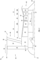
- FIG. 2 illustrate a portion of the combustor section 30 along the core flowpath 52 between the HPC section 29B and the HPT section 31A.
- This combustor section 30 includes the combustor 62, a diffuser plenum 68 and the one or more injector assemblies 64 (one visible in FIG. 2 ).
- the combustor 62 is disposed within (e.g., surrounded by) the diffuser plenum 68 - a compressed air plenum.
- This diffuser plenum 68 is formed by and/or within the engine housing 32 and its inner case 34.
- the diffuser plenum 68 receives the compressed core air from the HPC section 29B for subsequent provision into the combustion chamber 60.
- the 2 includes a fuel injector 70 mated with an air swirler structure 72.
- the fuel injector 70 injects the fuel into the combustion chamber 60.
- the air swirler structure 72 directs some of the core air from the diffuser plenum 68 into the combustion chamber 60 in a manner that facilitates mixing the core air with the injected fuel.
- One or more igniters (not shown) ignite the fuel-air mixture within the combustion chamber 60.
- One or more quench apertures 74A, 74B (generally referred to as “74") (e.g., dilution holes) in each wall 76A, 76B (generally referred to as "76") of the combustor 62 direct additional core air from the diffuser plenum 68 into the combustion chamber 60 to facilitate substantially complete burnout of (e.g., make stoichiometrically lean) the combustion products; e.g., the ignited fuel-air mixture.
- the combustor 62 may be configured as an annular combustor; e.g., an annular floating wall combustor.
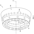
- the combustor 62 of FIGS. 2 and 3 includes an annular combustor bulkhead wall 78 ("bulkhead"), the tubular inner combustor wall 76A ("inner wall”), and the tubular outer combustor wall 76B ("outer wall”).
- the bulkhead 78 of FIG. 2 extends radially between and to the inner wall 76A and the outer wall 76B.
- the bulkhead 78 may be connected (e.g., mechanically fastened or otherwise attached) to the inner wall 76A and/or the outer wall 76B.
- Each combustor wall 76 projects axially along the axial centerline 22 out from the bulkhead 78 towards the HPT section 31A.
- the inner wall 76A of FIG. 2 projects axially to and may be connected to an (e.g., tubular) inner platform 80A of a downstream stator vane array 82 in the HPT section 31A.
- the outer wall 76B of FIG. 2 projects axially to and may be connected to an (e.g., tubular) outer platform 80B of the downstream stator vane array 82.
- the combustion chamber 60 is formed by and extends radially within the combustor 62 between and to the inner wall 76A and the outer wall 76B.
- the combustion chamber 60 is formed by and extends axially (in an upstream direction along the core flowpath 52) into the combustor 62 from the stator vane array 82 to the bulkhead 78.
- the combustion chamber 60 also extends within the combustor 62 circumferentially about (e.g., completely around) the axial centerline 22, which may configure the combustion chamber 60 as a full-hoop annulus.
- any one or more or all of the walls 76A, 76B, 78 may each be configured as a multi-walled structure; e.g., a hollow, dual-walled structure.
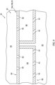
- Each wall 76A, 76B, 78 of FIG. 4 includes a combustor wall shell 84, a combustor wall heat shield 86 (e.g., a liner) and one or more combustor wall cooling cavities 88 (e.g., impingement cavities) formed by and (e.g., radially and/or axially) between the shell 84 and the heat shield 86.
- FIG. 4 is fluidly coupled with the diffuser plenum 68 through one or more cooling apertures 90 in the shell 84; e.g., impingement apertures.
- Each cooling cavity 88 of FIG. 4 is fluidly coupled with the combustion chamber 60 through one or more cooling apertures 92 in the heat shield 86; e.g., effusion apertures.
- various other multi-walled combustor wall structures are known in the art, and the present disclosure is not limited to any particular ones thereof.
- any one or more or all of the walls 76A, 76B and/or 78 of FIG. 2 may each alternatively be configured as a single-walled structure.
- each wall 76A, 76B, 78 may each be described below as the hollow, dual-walled structure.
- the stator vane array 82 includes the inner platform 80A, the outer platform 80B and a plurality of stator vanes 93 (one visible in FIG. 2 ).
- the stator vanes 93 are arranged circumferentially about the axial centerline 22 in an array; e.g., a circular array. Each of these stator vanes 93 extends radially across the core flowpath 52 between and to the inner platform 80A and the outer platform 80B.
- Each of the stator vanes 93 may also be connected to the inner platform 80A and/or the outer platform 80B.
- the stator vane array 82 and its stator vanes 93 are configured to turn and/or otherwise condition the combustion products exiting the combustion chamber 60 for interaction with a first stage of the HPT rotor 41 (see FIG. 1 ).
- the turbine engine 20 includes a fuel system 94 for delivering the fuel to the combustor 62.
- This fuel system 94 includes a fuel source 96 and the one or more fuel injectors 70.
- the fuel source 96 of FIG. 5 includes a fuel reservoir 98 and/or a fuel flow regulator 100; e.g., a valve and/or a pump.
- the fuel reservoir 98 is configured to store the fuel before, during and/or after turbine engine operation.
- the fuel reservoir 98 for example, may be configured as or otherwise include a tank, a cylinder, a pressure vessel, a bladder or any other type of fuel storage container.
- the fuel flow regulator 100 is configured to direct and/or meter a flow of the fuel from the fuel reservoir 98 to one or more or all of the fuel injectors 70.
- the fuel injectors 70 may be arranged circumferentially about the axial centerline 22 in an array. Each fuel injector 70 is configured to direct the fuel received from the fuel source 96 into the combustion chamber 60 for combustion.
- the fuel delivered by the fuel system 94 may be a non-hydrocarbon fuel; e.g., a hydrocarbon free fuel.
- the non-hydrocarbon fuel include, but are not limited to, hydrogen fuel (e.g., hydrogen (H 2 ) gas) and ammonia fuel (e.g., ammonia (NH 3 ) gas).
- the turbine engine 20 of FIG. 1 may thereby be configured as a non-hydrocarbon turbine engine; e.g., a hydrocarbon free turbine engine.
- the present disclosure is not limited to non-hydrocarbon turbine engines.
- the fuel delivered by the fuel system 94 for example, may alternatively be a hydrocarbon fuel such as, but not limited to, kerosene or jet fuel.
- the fuel system 94 may be configured as a hydrocarbon turbine engine.
- the fuel system 94 may be configured as a multi-fuel system operable to deliver, individually or in combination, multiple different fuels (e.g., a non-hydrocarbon fuel and a hydrocarbon fuel, etc.) for combustion within the combustion chamber 60.
- the turbine engine 20 of FIG. 1 may thereby be configured as a multi-fuel turbine engine; e.g., a dual-fuel turbine engine.
- the fuel delivered by the fuel system 94 may be described below as the non-hydrocarbon fuel; e.g., the hydrogen fuel.
- the combustor 62 and its walls 76A, 76B and 78 are subject to relatively hot combustion products within the combustion chamber 60 during turbine engine operation.
- a backside of each wall 76A, 76B, 78 of FIG. 2 is exposed to the core air flowing within the diffuser plenum 68.
- the core air may convectively air cool the respective wall 76A, 76B, 78.
- some of the core air may also be directed across one or more or all of the walls 76A, 76B and/or 78 from the diffuser plenum 68 into the combustion chamber 60 through cooling apertures of and/or cooling cavities within the respective wall(s) 76A, 76B and/or 78.
- the cooling apertures 90 may direct some of the core air from the diffuser plenum 68 into a respective cooling cavity 88 to impinge against a cooling cavity side of the heat shield 86. The core air may thereby impingement cool the heat shield 86.
- the cooling apertures 92 may subsequently direct at least some or all of the core air from within the respective cooling cavity 88 into the combustion chamber 60 to provide (e.g., form) an air film or films along a combustion chamber side of the heat shield 86.
- the core air may thereby film cool the heat shield 86 and/or provide an air buffer or buffers between the heat shield 86 and the relatively hot combustion products within the combustion chamber 60.
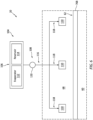
- the turbine engine 20 also includes a steam system 104 to provide steam cooling for the combustor 62 and at least one of its walls such as the outer wall 76B.
- This steam system 104 includes a steam source 106, a steam delivery circuit 108 and one or more steam injectors 110.
- the steam source 106 is configured to provide the steam to the steam delivery circuit 108 during turbine engine operation and, more particularly, during steam system operation.
- the steam source 106 may be configured as or otherwise include an evaporator 112, which may be or otherwise include a fluid-to-fluid heat exchanger and/or an electrical heater.
- the evaporator 112 is configured to evaporate water into the steam during steam system operation. The water may be received from various sources.
- the steam source 106 of FIG. 6 for example, includes a water reservoir 114 fluidly coupled with and upstream of the evaporator 112. This water reservoir 114 is configured to store the water before, during and/or after turbine engine operation.
- Examples of the water reservoir 114 include, but are not limited to, a tank, a cylinder, a pressure vessel, a bladder or any other type of water storage container. Briefly, the water may be supplied to the water reservoir 114 by recovering water vapor from the combustion products flowing through the core flowpath 52 (see FIG. 1 ) and/or from another water source onboard or offboard an aircraft.
- the steam delivery circuit 108 of FIG. 6 includes a supply circuit 116 and one or more feed circuits 118, where each feed circuit 118 is associated with a respective one of the steam injectors 110.
- the supply circuit 116 of FIG. 6 extends from an outlet from the steam source 106 to an interface with the feed circuits 118 such as a manifold. At the interface, the feed circuits 118 may be fluidly coupled in parallel to and downstream of the supply circuit 116.
- Each of the feed circuits 118 extends from the interface to an inlet of a respective one of the steam injectors 110.
- the steam delivery circuit 108 thereby fluidly couples the steam source 106 to the respective steam injectors 110.
- the steam directed through the steam delivery circuit 108 may be regulated based on cooling needs for the combustor 62 and its combustor wall 76B and/or based on a mode of turbine engine operation.
- the steam delivery circuit 108 of FIG. 6 includes a steam flow regulator 120.
- the steam flow regulator 120 is arranged (e.g., fluidly coupled inline) with the supply circuit 116.
- the steam flow regulator 120 is configured to selectively direct and/or meter a flow of the steam from the steam source 106 to the steam injectors 110.
- the steam flow regulator 120 may be configured as or otherwise include a control valve. This control valve may fully open, may fully close and/or may move to one or more partially open positions. While the steam flow regulator 120 is illustrated in FIG.
- steam flow regulator 120 may alternatively be arranged at the interface between the supply circuit 116 and the feed circuits 118, at an inlet to the supply circuit 116, or otherwise.
- One or more or all of the feed circuits 118 may also or alternatively be provided with its own steam flow regulator.
- the steam delivered to one or more or all of the steam injectors 110 may still also or alternatively be regulated by adjusting an amount of steam provided (e.g., produced) by the steam source 106.
- each of the steam injectors 110 is arranged within the diffuser plenum 68 next to the combustor 62 and the respective combustor wall 76B.
- Each steam injector 110 of FIG. 2 for example, is located radially between the engine housing 32 and the combustor 62.
- Each steam injector 110 is spaced radially inward from the engine housing 32 and its inner case 34.
- Each steam injector 110 is spaced radially outward from the combustor 62 and its respective combustor wall 76B.
- the steam injectors 110 are arranged axially along the combustor 62 and its respective combustor wall 76B. While the steam injectors 110 of FIG.
- the present disclosure is not limited to such an equispaced arrangement and may alternatively be asymmetrically spaced, for example, to target potential hot spots, etc.
- One or more or all of the steam injectors 110 may be disposed along a downstream portion of the combustor 62 and its respective combustor wall 76B.
- One or more or all of the steam injectors 110 may be arranged axially between the respective array of the quench apertures 74B and the downstream end of the combustor 62 and its respective combustor wall 76B at the stator vane array 82.
- Each steam injector 110 of FIG. 2 is thereby axially offset from the respective array of the quench apertures 74B.
- one or more or all of the steam injectors 110 may also or alternatively be arranged axially between the respective array of the quench apertures 74B and the bulkhead 78. It is also contemplated at least one of the steam injectors 110 (or an additional steam injector) may also or alternatively be axially aligned with the respective array of the quench apertures 74B. In general, however, the steam injector(s) 110 should not (at least significantly) obstruct the flow of the core air to the respective array of the quench apertures 74B and/or the flow of the core air for the air cooling.
- each steam injector 110 may be configured as a steam rail injector; e.g., a steam ring injector.
- the steam injector 110 of FIG. 8 extends circumferentially about (e.g., completely around) the combustor 62 and its respective combustor wall 76B.
- the steam injector 110 may thereby circumscribe the combustor 62 and its respective combustor wall 76B.
- the steam injector 110 of FIGS. 7 and 8 includes an internal steam passage 122 and one or more steam outlets 124.
- the steam passage 122 extends within the respective steam injector 110 axially between opposing axial ends 126 and 128 of the steam passage 122.
- the steam passage 122 extends within the respective steam injector 110 radially between opposing radial sides 130 and 132 of the steam passage 122.
- the steam passage 122 extends within the respective steam injectors 110 circumferentially about (e.g., completely around) the centerline axis 22.
- the steam passage 122 may thereby be formed as an annulus within a body 134 of the steam injector 110.
- This steam passage 122 is also fluidly coupled with and radially between the respective feed circuit 118 and the steam outlets 124.
- the steam passage 122 may thereby form a manifold for distributing steam received from the respective feed circuit 118 to the steam outlets 124.
- the steam outlets 124 are arranged circumferentially about (e.g., completely around) the respective combustor wall 76B and the axial centerline 22 in an array; e.g., a circular array. While the steam outlets 124 of FIG. 8 are equispaced circumferentially about the respective combustor wall 76B and the axial centerline 22, the present disclosure is not limited to such an equispaced arrangement and may alternatively be asymmetrically spaced or spaced in another pattern, for example, to target potential hot spots, etc. Each of the steam outlets 124 projects (e.g., radially inward) from the steam passage 122, through a sidewall 136 of the steam injector body 134, to the diffuser plenum 68. The steam outlets 124 thereby fluidly couple the steam passage 122 to the diffuser plenum 68.
- each steam injector 110 receives steam from the steam source 106 (see FIG. 6 ) through the steam delivery circuit 108. At each steam injector 110, the steam is distributed to from the steam passage 122 to the steam outlets 124 and directed out of the steam injector 110 into the diffuser plenum 68 and towards the respective combustor wall 76B.
- the steam injector 110 of FIGS. 7 and 8 may direct a flow (e.g., a jet) of the steam out from each steam outlet 124 and into the diffuser plenum 68 along a respective trajectory 138 to impinge against the backside of the respective combustor wall 76B.
- Each steam injector 110 may thereby impingement cool the combustor 62 and its respective combustor wall 76B with the steam, which impingement steam cooling may enhance the air cooling of the respective combustor wall 76B described above.
- the steam may then mix with the core air and flow across the respective combustor wall 76B with the cooling core air; e.g., through the cooling apertures 90, 92 and/or cooling cavities 88.
- the trajectory 138 of the steam flow exhausted from one, some or all of the steam outlets 124 may be perpendicular to the backside of the respective combustor wall 76B at or about, for example, a point or an area where the respective steam flow impinges against the respective combustor wall 76B.
- the trajectory 138 of the steam flow exhausted from one, some or all of the steam outlets 124 may be angularly offset from the backside of the respective combustor wall 76B at or about, for example, the impingement point or area by an acute angle 140.
- This acute angle 140 may be greater than forty-five degrees (45°); e.g., equal to or greater than sixty degrees (60°), seventy degrees (70°) or eighty degrees (80°).
- each steam injector 110 is described above as the steam rail (e.g., ring) injector.
- the present disclosure is not limited to such an exemplary steam injector configuration.
- each steam injector 110 may alternatively be configured as a steam blanket injector.
- the steam injector 110 of FIG. 10 may extend circumferentially about (e.g., completely around) the combustor 62 and its respective combustor wall 76B.
- the steam injector 110 of FIG. 10 also extends axially along the combustor 62 and its respective combustor wall 76B for an extended length.
- the steam outlets 124 may be arranged into a plurality of outlet sets / groups axially along the combustor 62 and its respective combustor wall 76B.
- the steam outlets 124 in each outlet set are arranged circumferentially about (e.g., completely around) the respective combustor wall 76B and the axial centerline 22 in an array; e.g., a circular array.
- the steam outlets 124 of FIG. 10 are arranged both circumferentially about and axially along the respective combustor wall 76B.
- the steam injector 110 of FIG. 10 may thereby blanket a relatively large area of the respective combustor wall 76B with the steam for cooling.
- the steam injector 110 may be configured with a lattice configuration.
- the steam injector 110 of FIG. 10 includes one or more ports 142 formed by a network of interconnected conduits 144. Each of the ports 142 extends (e.g., radially) through the steam injector 110 and thereby provides a path for the core air flowing within the diffuser plenum 68 to pass. With this arrangement, the core air may flow across the steam injector 110 to those areas generally covered by and/or targeted by the steam injector 110 for steam cooling.
- each steam injector 110 may have an annular body that circumscribes the combustor 62 and its respective combustor wall 76B (see FIG. 2 ).
- such an annular body may be broken up into multiple arcuate sections, where each arcuate section may be configured as a discrete one of the steam injectors 110.
- at least some or all of the steam injectors 110 of FIGS. 11B and 11C may be arranged circumferentially about the axial centerline 22 in an array.
- each of the steam injectors 110 may extend partially circumferentially about the axial centerline 22.
- each steam injector 110 any be configure as a discrete unit similar to the fuel injectors 70 of FIGS. 2 and 4 .
- one or more or all of the steam injectors 110 may each be configured as a steam showerhead injector.
- the steam outlets 124 in the steam injector 110 of FIG. 12 may be grouped together to blanket a region of the respective combustor wall 76B with the steam for cooling.
- the steam system 104 of FIG. 6 may be operated in various modes. For example, when turbine engine 20 is operating at low throttle or idle (e.g., during engine warmup, engine cooldown or for aircraft descent), the steam delivery circuit 108 may direct little or no steam to one or more or all of the steam injectors 110.
- the combustor 62 may therefore (e.g., only or substantially) be cooled using cooling air; e.g., the core air from the diffuser plenum 68.
- the steam delivery circuit 108 may direct the steam to one or more or all of the steam injectors 110.
- the steam may thereby bolster the air cooling of the combustor 62 while also targeting the additional cooling to select areas.
- the steam system 104 may provide additional cooling capability using the steam, but regularly provide the air cooling throughout the engine cycle. Note, providing air cooling may be particularly useful at turbine engine startup where, for example, the steam may not be available until after the turbine engine 20 is warmed up.
- the steam system 104 may be included in various turbine engines other than the one described above.
- the steam system 104 may be included in a geared turbine engine where a geartrain connects one or more shafts to one or more rotors in a fan section, a compressor section and/or any other engine section.
- the steam system 104 may be included in a turbine engine configured without a geartrain; e.g., a direct drive turbine engine.
- the steam system 104 may be included in a geared or non-geared turbine engine configured with a single spool, with two spools (e.g., see FIG. 1 ), or with more than two spools.
- the turbine engine may be configured as a turbofan engine, a turbojet engine, a turboprop engine, a turboshaft engine, a propfan engine, a pusher fan engine or any other type of turbine engine.
- the turbine engine may alternatively be configured as an auxiliary power unit (APU) or an industrial gas turbine engine.
- APU auxiliary power unit
- the present disclosure therefore is not limited to any particular types or configurations of turbine engines.
Landscapes
- Engineering & Computer Science (AREA)
- Chemical & Material Sciences (AREA)
- Combustion & Propulsion (AREA)
- Mechanical Engineering (AREA)
- General Engineering & Computer Science (AREA)
- Turbine Rotor Nozzle Sealing (AREA)
Abstract
Description
- This disclosure relates generally to a turbine engine and, more particularly, to utilizing steam during operation of the turbine engine.
- As government emissions standards tighten, interest in alternative fuels for gas turbine engines continues to grow. There is interest, for example, in fueling a gas turbine engine with hydrogen (H2) fuel rather than a traditional hydrocarbon fuel such as kerosine to reduce greenhouse emissions. Combustion products produced by combusting hydrogen (H2) fuel include water vapor. Various systems and methods are known in the art for recovering the water vapor. Various system and methods are also known in the art for producing and utilizing steam from the recovered water vapor. While these known systems and methods have various advantages, there is still room in the art for improvement.
- According to an aspect of the present disclosure, an assembly is provided for a turbine engine. This assembly includes a housing, a combustor and a steam system. The housing includes an air plenum. The combustor is disposed within the air plenum. The combustor includes a combustion chamber and a combustor wall between the combustion chamber and the air plenum. The steam system includes a steam injector arranged within the air plenum next to the combustor wall. The steam system is configured to inject steam out of the steam injector and into the air plenum to impinge against the combustor wall.
- According to another aspect of the present disclosure, another assembly is provided for a turbine engine. This assembly includes a combustor and a first steam ring. The combustor includes a combustion chamber and a combustor wall forming a peripheral boundary of the combustion chamber. The combustor wall extends circumferentially around and axially along an axial centerline. A first steam ring injector is disposed outside of the combustor and next to the combustor wall. The first steam ring injector includes a plurality of first steam outlets arranged circumferentially around the combustor wall. The first steam ring injector is configured to direct steam out of the first steam outlets to cool the combustor wall.
- According to still another aspect of the present disclosure, another assembly is provided for a turbine engine. This assembly includes a combustor and a steam blanket injector. The combustor includes a combustion chamber and a combustor wall forming a peripheral boundary of the combustion chamber. The combustor wall extends circumferentially around and axially along an axial centerline. The steam blanket injector is disposed outside of the combustor and next to the combustor wall. The steam blanket injector includes a plurality of steam outlets and a plurality of ports. The steam outlets are arranged circumferentially around and axially along the combustor wall. The steam blanket injector is configured to direct steam out of the steam outlets to cool the combustor wall. Each of the ports extends through the steam blanket injector to facilitate airflow across the steam blanket injector.
- The following optional features may be applied to any of the above aspects:
The assembly may also include a second steam ring injector disposed outside of the combustor, next to the combustor wall and axially spaced from the first steam ring injector. The second steam ring injector may include a plurality of second steam outlets arranged circumferentially around the combustor wall. The second steam ring injector may be configured to inject additional steam out of the second steam outlets to cool the combustor wall. - The assembly may also include a compressor section and a diffuser plenum fluidly coupled with and downstream of the compressor section. The combustor and the first steam ring injector may be arranged within the diffuser plenum.
- The steam system may be configured to direct a flow of the steam out of the steam injector and into the air plenum along a trajectory to impinge against the combustor wall. The trajectory may be perpendicular to the combustor wall.
- The steam system may be configured to direct: a first flow of the steam out of the steam injector and into the air plenum to impinge against a first area of the combustor wall; and a second flow of the steam out of the steam injector and into the air plenum to impinge against a second area of the combustor wall.
- The steam system may be configured to direct a flow of the steam out of the steam injector and into the air plenum along a trajectory to impinge against the combustor wall. The trajectory may be angularly offset from the combustor wall by an acute angle greater than forty-five degrees.
- The steam injector may include a plurality of steam outlets. The steam system may be configured to direct the steam through the steam outlets into the air plenum to impinge against the combustor wall.
- The combustor wall may extend axially along and circumferentially about a centerline. At least some of the steam outlets may be arranged axially along the combustor wall.
- The combustor wall may extend axially along and circumferentially about a centerline. At least some of the steam outlets may be arranged circumferentially about the combustor wall.
- The steam injector may be configured as a steam showerhead injector.
- The steam injector may be configured as a steam rail injector extending circumferentially about the combustor wall.
- The steam injector may be configured as a steam blanket injector extending axially along and circumferentially about the combustor wall.
- The steam blanket injector may have a lattice configuration.
- The steam injector may be a first steam injector, and the steam system may also include a second steam injector arranged within the air plenum next to the combustor wall. The steam system may be configured to inject additional steam out of the second steam injector and into the air plenum to impinge against the combustor wall.
- The combustor wall may extend axially along and circumferentially about a centerline. The second steam injector may be axially spaced from the first steam injector along the combustor wall.
- The combustor wall may include a plurality of cooling apertures configured to receive cooling air from the air plenum.
- The combustor wall may include an array of quench apertures. The steam injector may be offset from the array of quench apertures.
- The assembly may also include a compressor section. The air plenum may be fluidly coupled with and downstream of the compressor section.
- The present disclosure may include any one or more of the individual features disclosed above and/or below alone or in any combination thereof.
- The foregoing features and the operation of the invention will become more apparent in light of the following description and the accompanying drawings.
-
-
FIG. 1 is a partial schematic illustration of a gas turbine engine. -
FIG. 2 is a partial schematic illustration of a combustor section between a compressor section and a turbine section. -
FIG. 3 is a perspective illustration of a combustor. -
FIG. 4 is a partial sectional illustration of a combustor wall. -
FIG. 5 is a schematic illustration of a fuel system configured with the combustor section. -
FIG. 6 is a schematic illustration of a steam system arranged with the combustor. -
FIG. 7 is a sectional illustration of a portion of the steam system with the combustor. -
FIG. 8 is another sectional illustration of a portion of the steam system with the combustor. -
FIGS. 9A and 9B are schematic illustrations of various steam trajectories. -
FIG. 10 is a schematic illustration of a portion of another steam injector with the combustor. -
FIGS. 11A-C are schematic illustrations of various steam injectors arrangements. -
FIG. 12 is a schematic illustration of another steam injector with the combustor. -
FIG. 1 is a side sectional illustration of agas turbine engine 20 for an aircraft propulsion system. Thisturbine engine 20 extends axially along anaxial centerline 22 between a forward,upstream end 24 and an aft,downstream end 26. Theturbine engine 20 includes afan section 28, acompressor section 29, acombustor section 30 and aturbine section 31. Thecompressor section 29 ofFIG. 1 includes a low pressure compressor (LPC)section 29A and a high pressure compressor (HPC)section 29B. Theturbine section 31 ofFIG. 1 includes a high pressure turbine (HPT)section 31A and a low pressure turbine (LPT)section 31B. - The engine sections 28-31B of
FIG. 1 are arranged sequentially along theaxial centerline 22 within anengine housing 32. Thisengine housing 32 includes an inner case 34 (e.g., a core case) and an outer case 36 (e.g., a fan case). Theinner case 34 may house one or more of theengine sections 29A-31B; e.g., a core of theturbine engine 20. Theouter case 36 may house at least thefan section 28. - Each of the
engine sections - The
fan rotor 38 is connected to ageartrain 44, for example, through afan shaft 46. Thegeartrain 44 and theLPC rotor 39 are connected to and driven by theLPT rotor 42 through alow speed shaft 47. TheHPC rotor 40 is connected to and driven by theHPT rotor 41 through ahigh speed shaft 48. The engine shafts 46-48 are rotatably supported by a plurality of bearings; e.g., rolling element and/or thrust bearings. Each of these bearings is connected to theengine housing 32 by at least one stationary structure such as, for example, an annular support strut. - During engine operation, air enters the
turbine engine 20 through anairflow inlet 50 into theturbine engine 20. This air is directed through thefan section 28 and into acore flowpath 52 and abypass flowpath 54. Thecore flowpath 52 extends sequentially through theengine sections 29A-31B (e.g., the engine core) from aninlet 56 into thecore flowpath 52 to anexhaust 58 from thecore flowpath 52. The air within thecore flowpath 52 may be referred to as "core air". Thebypass flowpath 54 extends through a bypass duct, and bypasses the engine core. The air within thebypass flowpath 54 may be referred to as "bypass air". - The core air is compressed by the
LPC rotor 39 and theHPC rotor 40 and directed into a (e.g., annular)combustion chamber 60 of a (e.g., annular)combustor 62 in thecombustor section 30. Fuel is injected by one or more fuel injector assemblies 64 (one visible inFIG. 1 ) into thecombustion chamber 60 and mixed with the compressed core air to provide a fuel-air mixture. This fuel-air mixture is ignited and combustion products thereof flow through and sequentially cause theHPT rotor 41 and theLPT rotor 42 to rotate before being directed out of theturbine engine 20 through thecore exhaust 58. The rotation of theHPT rotor 41 and theLPT rotor 42 respectively drive rotation of theHPC rotor 40 and theLPC rotor 39 and, thus, compression of the air received from thecore inlet 56. The rotation of theLPT rotor 42 also drives rotation of thefan rotor 38, which propels the bypass air through thebypass flowpath 54 and out of theturbine engine 20 through anexhaust 66 from thebypass flowpath 54. The propulsion of the bypass air may account for a majority of thrust generated by theturbine engine 20. -
FIG. 2 illustrate a portion of thecombustor section 30 along thecore flowpath 52 between theHPC section 29B and theHPT section 31A. Thiscombustor section 30 includes thecombustor 62, adiffuser plenum 68 and the one or more injector assemblies 64 (one visible inFIG. 2 ). Briefly, thecombustor 62 is disposed within (e.g., surrounded by) the diffuser plenum 68 - a compressed air plenum. Thisdiffuser plenum 68 is formed by and/or within theengine housing 32 and itsinner case 34. Thediffuser plenum 68 receives the compressed core air from theHPC section 29B for subsequent provision into thecombustion chamber 60. Eachinjector assembly 64 ofFIG. 2 includes afuel injector 70 mated with anair swirler structure 72. Thefuel injector 70 injects the fuel into thecombustion chamber 60. The air swirlerstructure 72 directs some of the core air from thediffuser plenum 68 into thecombustion chamber 60 in a manner that facilitates mixing the core air with the injected fuel. One or more igniters (not shown) ignite the fuel-air mixture within thecombustion chamber 60. One or more quenchapertures wall combustor 62 direct additional core air from thediffuser plenum 68 into thecombustion chamber 60 to facilitate substantially complete burnout of (e.g., make stoichiometrically lean) the combustion products; e.g., the ignited fuel-air mixture. - The
combustor 62 may be configured as an annular combustor; e.g., an annular floating wall combustor. Thecombustor 62 ofFIGS. 2 and3 , for example, includes an annular combustor bulkhead wall 78 ("bulkhead"), the tubularinner combustor wall 76A ("inner wall"), and the tubularouter combustor wall 76B ("outer wall"). Thebulkhead 78 ofFIG. 2 extends radially between and to theinner wall 76A and theouter wall 76B. Thebulkhead 78 may be connected (e.g., mechanically fastened or otherwise attached) to theinner wall 76A and/or theouter wall 76B. Each combustor wall 76 projects axially along theaxial centerline 22 out from thebulkhead 78 towards theHPT section 31A. Theinner wall 76A ofFIG. 2 , for example, projects axially to and may be connected to an (e.g., tubular)inner platform 80A of a downstreamstator vane array 82 in theHPT section 31A. Theouter wall 76B ofFIG. 2 projects axially to and may be connected to an (e.g., tubular)outer platform 80B of the downstreamstator vane array 82. With the arrangement ofFIG. 2 , thecombustion chamber 60 is formed by and extends radially within thecombustor 62 between and to theinner wall 76A and theouter wall 76B. Thecombustion chamber 60 is formed by and extends axially (in an upstream direction along the core flowpath 52) into the combustor 62 from thestator vane array 82 to thebulkhead 78. Thecombustion chamber 60 also extends within thecombustor 62 circumferentially about (e.g., completely around) theaxial centerline 22, which may configure thecombustion chamber 60 as a full-hoop annulus. - Referring to
FIG. 4 , any one or more or all of thewalls wall FIG. 4 , for example, includes acombustor wall shell 84, a combustor wall heat shield 86 (e.g., a liner) and one or more combustor wall cooling cavities 88 (e.g., impingement cavities) formed by and (e.g., radially and/or axially) between theshell 84 and theheat shield 86. Each coolingcavity 88 ofFIG. 4 is fluidly coupled with thediffuser plenum 68 through one ormore cooling apertures 90 in theshell 84; e.g., impingement apertures. Each coolingcavity 88 ofFIG. 4 is fluidly coupled with thecombustion chamber 60 through one ormore cooling apertures 92 in theheat shield 86; e.g., effusion apertures. Of course, various other multi-walled combustor wall structures are known in the art, and the present disclosure is not limited to any particular ones thereof. Furthermore, it is contemplated any one or more or all of thewalls FIG. 2 may each alternatively be configured as a single-walled structure. Theshell 84 ofFIG. 4 , for example, may be omitted and theheat shield 86 may form a single walled liner / wall. However, for ease of description, eachwall - Referring to
FIG. 2 , thestator vane array 82 includes theinner platform 80A, theouter platform 80B and a plurality of stator vanes 93 (one visible inFIG. 2 ). The stator vanes 93 are arranged circumferentially about theaxial centerline 22 in an array; e.g., a circular array. Each of thesestator vanes 93 extends radially across thecore flowpath 52 between and to theinner platform 80A and theouter platform 80B. Each of thestator vanes 93 may also be connected to theinner platform 80A and/or theouter platform 80B. Thestator vane array 82 and itsstator vanes 93 are configured to turn and/or otherwise condition the combustion products exiting thecombustion chamber 60 for interaction with a first stage of the HPT rotor 41 (seeFIG. 1 ). - Referring to
FIG. 5 , theturbine engine 20 includes afuel system 94 for delivering the fuel to thecombustor 62. Thisfuel system 94 includes afuel source 96 and the one ormore fuel injectors 70. Thefuel source 96 ofFIG. 5 includes afuel reservoir 98 and/or afuel flow regulator 100; e.g., a valve and/or a pump. Thefuel reservoir 98 is configured to store the fuel before, during and/or after turbine engine operation. Thefuel reservoir 98, for example, may be configured as or otherwise include a tank, a cylinder, a pressure vessel, a bladder or any other type of fuel storage container. Thefuel flow regulator 100 is configured to direct and/or meter a flow of the fuel from thefuel reservoir 98 to one or more or all of thefuel injectors 70. Thefuel injectors 70 may be arranged circumferentially about theaxial centerline 22 in an array. Eachfuel injector 70 is configured to direct the fuel received from thefuel source 96 into thecombustion chamber 60 for combustion. - The fuel delivered by the
fuel system 94 may be a non-hydrocarbon fuel; e.g., a hydrocarbon free fuel. Examples of the non-hydrocarbon fuel include, but are not limited to, hydrogen fuel (e.g., hydrogen (H2) gas) and ammonia fuel (e.g., ammonia (NH3) gas). Theturbine engine 20 ofFIG. 1 may thereby be configured as a non-hydrocarbon turbine engine; e.g., a hydrocarbon free turbine engine. The present disclosure, however, is not limited to non-hydrocarbon turbine engines. The fuel delivered by thefuel system 94, for example, may alternatively be a hydrocarbon fuel such as, but not limited to, kerosene or jet fuel. Theturbine engine 20 ofFIG. 1 may thereby be configured as a hydrocarbon turbine engine. Alternatively, thefuel system 94 may be configured as a multi-fuel system operable to deliver, individually or in combination, multiple different fuels (e.g., a non-hydrocarbon fuel and a hydrocarbon fuel, etc.) for combustion within thecombustion chamber 60. Theturbine engine 20 ofFIG. 1 may thereby be configured as a multi-fuel turbine engine; e.g., a dual-fuel turbine engine. However, for ease of description, the fuel delivered by thefuel system 94 may be described below as the non-hydrocarbon fuel; e.g., the hydrogen fuel. - Referring to
FIG. 2 , thecombustor 62 and itswalls combustion chamber 60 during turbine engine operation. To cool the combustor 62 and itswalls wall FIG. 2 is exposed to the core air flowing within thediffuser plenum 68. As the core air flows within thediffuser plenum 68 and along at least a portion or an entirety of the backside of eachwall respective wall combustor 62, some of the core air may also be directed across one or more or all of thewalls diffuser plenum 68 into thecombustion chamber 60 through cooling apertures of and/or cooling cavities within the respective wall(s) 76A, 76B and/or 78. For example, referring toFIG. 4 , the coolingapertures 90 may direct some of the core air from thediffuser plenum 68 into arespective cooling cavity 88 to impinge against a cooling cavity side of theheat shield 86. The core air may thereby impingement cool theheat shield 86. The cooling apertures 92 may subsequently direct at least some or all of the core air from within therespective cooling cavity 88 into thecombustion chamber 60 to provide (e.g., form) an air film or films along a combustion chamber side of theheat shield 86. The core air may thereby film cool theheat shield 86 and/or provide an air buffer or buffers between theheat shield 86 and the relatively hot combustion products within thecombustion chamber 60. - Combustion product temperatures may continue to increase in an effort to improve turbine engine efficiency and/or facilitate improved turbine engine performance, particularly when using alternative fuels such as hydrogen fuel or the like. However, utilizing additional core air from the
core flowpath 52 and itsdiffuser plenum 68 to provide additional combustor air cooling may be counterproductive since that core air is no longer available (at least primarily) for the combustion process. Therefore, referring toFIG. 6 , theturbine engine 20 also includes asteam system 104 to provide steam cooling for thecombustor 62 and at least one of its walls such as theouter wall 76B. Thissteam system 104 includes asteam source 106, asteam delivery circuit 108 and one ormore steam injectors 110. - The
steam source 106 is configured to provide the steam to thesteam delivery circuit 108 during turbine engine operation and, more particularly, during steam system operation. Thesteam source 106, for example, may be configured as or otherwise include anevaporator 112, which may be or otherwise include a fluid-to-fluid heat exchanger and/or an electrical heater. Theevaporator 112 is configured to evaporate water into the steam during steam system operation. The water may be received from various sources. Thesteam source 106 ofFIG. 6 , for example, includes awater reservoir 114 fluidly coupled with and upstream of theevaporator 112. Thiswater reservoir 114 is configured to store the water before, during and/or after turbine engine operation. Examples of thewater reservoir 114 include, but are not limited to, a tank, a cylinder, a pressure vessel, a bladder or any other type of water storage container. Briefly, the water may be supplied to thewater reservoir 114 by recovering water vapor from the combustion products flowing through the core flowpath 52 (seeFIG. 1 ) and/or from another water source onboard or offboard an aircraft. - The
steam delivery circuit 108 ofFIG. 6 includes asupply circuit 116 and one ormore feed circuits 118, where eachfeed circuit 118 is associated with a respective one of thesteam injectors 110. Thesupply circuit 116 ofFIG. 6 extends from an outlet from thesteam source 106 to an interface with thefeed circuits 118 such as a manifold. At the interface, thefeed circuits 118 may be fluidly coupled in parallel to and downstream of thesupply circuit 116. Each of thefeed circuits 118 extends from the interface to an inlet of a respective one of thesteam injectors 110. Thesteam delivery circuit 108 thereby fluidly couples thesteam source 106 to therespective steam injectors 110. - The steam directed through the
steam delivery circuit 108 may be regulated based on cooling needs for thecombustor 62 and itscombustor wall 76B and/or based on a mode of turbine engine operation. Thesteam delivery circuit 108 ofFIG. 6 , for example, includes asteam flow regulator 120. Thesteam flow regulator 120 is arranged (e.g., fluidly coupled inline) with thesupply circuit 116. Thesteam flow regulator 120 is configured to selectively direct and/or meter a flow of the steam from thesteam source 106 to thesteam injectors 110. For example, thesteam flow regulator 120 may be configured as or otherwise include a control valve. This control valve may fully open, may fully close and/or may move to one or more partially open positions. While thesteam flow regulator 120 is illustrated inFIG. 6 as being part of thesupply circuit 116, thatsteam flow regulator 120 may alternatively be arranged at the interface between thesupply circuit 116 and thefeed circuits 118, at an inlet to thesupply circuit 116, or otherwise. One or more or all of thefeed circuits 118 may also or alternatively be provided with its own steam flow regulator. Furthermore, it is contemplated the steam delivered to one or more or all of thesteam injectors 110 may still also or alternatively be regulated by adjusting an amount of steam provided (e.g., produced) by thesteam source 106. - Referring to
FIG. 2 , each of thesteam injectors 110 is arranged within thediffuser plenum 68 next to thecombustor 62 and therespective combustor wall 76B. Eachsteam injector 110 ofFIG. 2 , for example, is located radially between theengine housing 32 and thecombustor 62. Eachsteam injector 110 is spaced radially inward from theengine housing 32 and itsinner case 34. Eachsteam injector 110 is spaced radially outward from thecombustor 62 and itsrespective combustor wall 76B. The steam injectors 110 are arranged axially along thecombustor 62 and itsrespective combustor wall 76B. While thesteam injectors 110 ofFIG. 2 are equispaced axially along therespective combustor wall 76B and theaxial centerline 22, the present disclosure is not limited to such an equispaced arrangement and may alternatively be asymmetrically spaced, for example, to target potential hot spots, etc. - One or more or all of the
steam injectors 110 may be disposed along a downstream portion of thecombustor 62 and itsrespective combustor wall 76B. One or more or all of thesteam injectors 110, for example, may be arranged axially between the respective array of the quenchapertures 74B and the downstream end of thecombustor 62 and itsrespective combustor wall 76B at thestator vane array 82. Eachsteam injector 110 ofFIG. 2 is thereby axially offset from the respective array of the quenchapertures 74B. However, it is contemplated one or more or all of the steam injectors 110 (or additional steam injectors) may also or alternatively be arranged axially between the respective array of the quenchapertures 74B and thebulkhead 78. It is also contemplated at least one of the steam injectors 110 (or an additional steam injector) may also or alternatively be axially aligned with the respective array of the quenchapertures 74B. In general, however, the steam injector(s) 110 should not (at least significantly) obstruct the flow of the core air to the respective array of the quenchapertures 74B and/or the flow of the core air for the air cooling. - Referring to
FIGS. 7 and8 , eachsteam injector 110 may be configured as a steam rail injector; e.g., a steam ring injector. Thesteam injector 110 ofFIG. 8 , for example, extends circumferentially about (e.g., completely around) thecombustor 62 and itsrespective combustor wall 76B. Thesteam injector 110 may thereby circumscribe thecombustor 62 and itsrespective combustor wall 76B. Thesteam injector 110 ofFIGS. 7 and8 includes aninternal steam passage 122 and one ormore steam outlets 124. - Referring to
FIG. 7 , thesteam passage 122 extends within therespective steam injector 110 axially between opposingaxial ends steam passage 122. Thesteam passage 122 extends within therespective steam injector 110 radially between opposingradial sides steam passage 122. Referring toFIG. 8 , thesteam passage 122 extends within therespective steam injectors 110 circumferentially about (e.g., completely around) thecenterline axis 22. Thesteam passage 122 may thereby be formed as an annulus within abody 134 of thesteam injector 110. Thissteam passage 122 is also fluidly coupled with and radially between therespective feed circuit 118 and thesteam outlets 124. Thesteam passage 122 may thereby form a manifold for distributing steam received from therespective feed circuit 118 to thesteam outlets 124. - The
steam outlets 124 are arranged circumferentially about (e.g., completely around) therespective combustor wall 76B and theaxial centerline 22 in an array; e.g., a circular array. While thesteam outlets 124 ofFIG. 8 are equispaced circumferentially about therespective combustor wall 76B and theaxial centerline 22, the present disclosure is not limited to such an equispaced arrangement and may alternatively be asymmetrically spaced or spaced in another pattern, for example, to target potential hot spots, etc. Each of thesteam outlets 124 projects (e.g., radially inward) from thesteam passage 122, through asidewall 136 of thesteam injector body 134, to thediffuser plenum 68. Thesteam outlets 124 thereby fluidly couple thesteam passage 122 to thediffuser plenum 68. - During steam system operation, each
steam injector 110 receives steam from the steam source 106 (seeFIG. 6 ) through thesteam delivery circuit 108. At eachsteam injector 110, the steam is distributed to from thesteam passage 122 to thesteam outlets 124 and directed out of thesteam injector 110 into thediffuser plenum 68 and towards therespective combustor wall 76B. Thesteam injector 110 ofFIGS. 7 and8 , for example, may direct a flow (e.g., a jet) of the steam out from eachsteam outlet 124 and into thediffuser plenum 68 along arespective trajectory 138 to impinge against the backside of therespective combustor wall 76B. Eachsteam injector 110 may thereby impingement cool the combustor 62 and itsrespective combustor wall 76B with the steam, which impingement steam cooling may enhance the air cooling of therespective combustor wall 76B described above. The steam may then mix with the core air and flow across therespective combustor wall 76B with the cooling core air; e.g., through the coolingapertures cavities 88. - In some embodiments, referring to
FIG. 9A , thetrajectory 138 of the steam flow exhausted from one, some or all of thesteam outlets 124 may be perpendicular to the backside of therespective combustor wall 76B at or about, for example, a point or an area where the respective steam flow impinges against therespective combustor wall 76B. In other embodiments, referring toFIG. 9B , thetrajectory 138 of the steam flow exhausted from one, some or all of thesteam outlets 124 may be angularly offset from the backside of therespective combustor wall 76B at or about, for example, the impingement point or area by anacute angle 140. Thisacute angle 140 may be greater than forty-five degrees (45°); e.g., equal to or greater than sixty degrees (60°), seventy degrees (70°) or eighty degrees (80°). - Each
steam injector 110 is described above as the steam rail (e.g., ring) injector. The present disclosure, however, is not limited to such an exemplary steam injector configuration. For example, referring toFIG. 10 , eachsteam injector 110 may alternatively be configured as a steam blanket injector. Like the steam rail injector described above, thesteam injector 110 ofFIG. 10 may extend circumferentially about (e.g., completely around) thecombustor 62 and itsrespective combustor wall 76B. Thesteam injector 110 ofFIG. 10 , however, also extends axially along thecombustor 62 and itsrespective combustor wall 76B for an extended length. With this configuration, thesteam outlets 124 may be arranged into a plurality of outlet sets / groups axially along thecombustor 62 and itsrespective combustor wall 76B. Thesteam outlets 124 in each outlet set are arranged circumferentially about (e.g., completely around) therespective combustor wall 76B and theaxial centerline 22 in an array; e.g., a circular array. Thus, thesteam outlets 124 ofFIG. 10 are arranged both circumferentially about and axially along therespective combustor wall 76B. Thesteam injector 110 ofFIG. 10 may thereby blanket a relatively large area of therespective combustor wall 76B with the steam for cooling. - To reduce an airflow obstruction to the
respective combustor wall 76B, thesteam injector 110 may be configured with a lattice configuration. Thesteam injector 110 ofFIG. 10 , for example, includes one ormore ports 142 formed by a network ofinterconnected conduits 144. Each of theports 142 extends (e.g., radially) through thesteam injector 110 and thereby provides a path for the core air flowing within thediffuser plenum 68 to pass. With this arrangement, the core air may flow across thesteam injector 110 to those areas generally covered by and/or targeted by thesteam injector 110 for steam cooling. - In some embodiments, referring to
FIG. 11A , eachsteam injector 110 may have an annular body that circumscribes thecombustor 62 and itsrespective combustor wall 76B (seeFIG. 2 ). In other embodiments, referring toFIGS. 11B and 11C , such an annular body may be broken up into multiple arcuate sections, where each arcuate section may be configured as a discrete one of thesteam injectors 110. For example, at least some or all of thesteam injectors 110 ofFIGS. 11B and 11C may be arranged circumferentially about theaxial centerline 22 in an array. Referring toFIG. 11B , each of thesteam injectors 110 may extend partially circumferentially about theaxial centerline 22. Alternatively, referring toFIG. 11C , eachsteam injector 110 any be configure as a discrete unit similar to thefuel injectors 70 ofFIGS. 2 and4 . - In some embodiments, referring to
FIG. 12 , one or more or all of thesteam injectors 110 may each be configured as a steam showerhead injector. Thesteam outlets 124 in thesteam injector 110 ofFIG. 12 , for example, may be grouped together to blanket a region of therespective combustor wall 76B with the steam for cooling. - The
steam system 104 ofFIG. 6 may be operated in various modes. For example, whenturbine engine 20 is operating at low throttle or idle (e.g., during engine warmup, engine cooldown or for aircraft descent), thesteam delivery circuit 108 may direct little or no steam to one or more or all of thesteam injectors 110. Thecombustor 62 may therefore (e.g., only or substantially) be cooled using cooling air; e.g., the core air from thediffuser plenum 68. However, when theturbine engine 20 is operating at medium throttle or high throttle (e.g., for aircraft cruise or aircraft takeoff), thesteam delivery circuit 108 may direct the steam to one or more or all of thesteam injectors 110. The steam may thereby bolster the air cooling of thecombustor 62 while also targeting the additional cooling to select areas. With this operability, thesteam system 104 may provide additional cooling capability using the steam, but regularly provide the air cooling throughout the engine cycle. Note, providing air cooling may be particularly useful at turbine engine startup where, for example, the steam may not be available until after theturbine engine 20 is warmed up. - The
steam system 104 may be included in various turbine engines other than the one described above. Thesteam system 104, for example, may be included in a geared turbine engine where a geartrain connects one or more shafts to one or more rotors in a fan section, a compressor section and/or any other engine section. Alternatively, thesteam system 104 may be included in a turbine engine configured without a geartrain; e.g., a direct drive turbine engine. Thesteam system 104 may be included in a geared or non-geared turbine engine configured with a single spool, with two spools (e.g., seeFIG. 1 ), or with more than two spools. The turbine engine may be configured as a turbofan engine, a turbojet engine, a turboprop engine, a turboshaft engine, a propfan engine, a pusher fan engine or any other type of turbine engine. The turbine engine may alternatively be configured as an auxiliary power unit (APU) or an industrial gas turbine engine. The present disclosure therefore is not limited to any particular types or configurations of turbine engines. - While various embodiments of the present disclosure have been described, it will be apparent to those of ordinary skill in the art that many more embodiments and implementations are possible within the scope of the disclosure. For example, the present disclosure as described herein includes several aspects and embodiments that include particular features. Although these features may be described individually, it is within the scope of the present disclosure that some or all of these features may be combined with any one of the aspects and remain within the scope of the disclosure. Accordingly, the present disclosure is not to be restricted except in light of the attached claims and their equivalents.
Claims (15)
- An assembly for a turbine engine (20), comprising:a housing (32) comprising an air plenum (68);a combustor (62) disposed within the air plenum (68), the combustor (62) including a combustion chamber (60) and a combustor wall (76B) between the combustion chamber (60) and the air plenum (68); anda steam system (104) comprising a steam injector (110) arranged within the air plenum (68) next to the combustor wall (76B), the steam system (104) configured to inject steam out of the steam injector (110) and into the air plenum (68) to impinge against the combustor wall (76B).
- The assembly of claim 1, wherein:the steam system (104) is configured to direct a flow of the steam out of the steam injector (110) and into the air plenum (68) along a trajectory (138) to impinge against the combustor wall (76B); andthe trajectory (138) is perpendicular to the combustor wall (76B).
- The assembly of claim 1, wherein:the steam system (104) is configured to direct a flow of the steam out of the steam injector (110) and into the air plenum (68) along a trajectory (138) to impinge against the combustor wall (76B); andthe trajectory (138) is angularly offset from the combustor wall (76B) by an acute angle (140) greater than forty-five degrees.
- The assembly of claim 1, 2 or 3, wherein the steam system (104) is configured to directa first flow of the steam out of the steam injector (110) and into the air plenum (68) to impinge against a first area of the combustor wall (76B); anda second flow of the steam out of the steam injector (110) and into the air plenum to impinge against a second area of the combustor wall (76B).
- The assembly of any preceding claim, wherein:the steam injector (110) includes a plurality of steam outlets (124); andthe steam system (104) is configured to direct the steam through the plurality of the steam outlets (124) into the air plenum (68) to impinge against the combustor wall (76B).
- The assembly of claim 5, wherein:the combustor wall (76B) extends axially along and circumferentially about a centerline (22); andat least some of the plurality of steam outlets (124) are arranged axially along the combustor wall (76B).
- The assembly of claim 5 or 6, wherein:the combustor wall (76B) extends axially along and circumferentially about a centerline (22); andat least some of the plurality of steam outlets (124) are arranged circumferentially about the combustor wall (76B).
- The assembly of any preceding claim, wherein:the steam injector (110) is configured as a steam showerhead injector; orthe steam injector (110) is configured as a steam rail injector extending circumferentially about the combustor wall (76B).
- The assembly of any of claims 1 to 7, wherein the steam injector (110) is configured as a steam blanket injector extending axially along and circumferentially about the combustor wall (76B),
wherein, optionally, the steam blanket injector has a lattice configuration. - The assembly of any preceding claim, wherein:the steam injector (110) is a first steam injector (110), and the steam system (104) further comprises a second steam injector (110) arranged within the air plenum (68) next to the combustor wall (76B); andthe steam system (104) is configured to inject additional steam out of the second steam injector (110) and into the air plenum (68) to impinge against the combustor wall (76B).wherein, optionally:the combustor wall (76B) extends axially along and circumferentially about a centerline (22); andthe second steam injector (110) is axially spaced from the first steam injector (110) along the combustor wall (76B).
- The assembly of any preceding claim, wherein:the combustor wall (76B) comprises a plurality of cooling apertures (90) configured to receive cooling air from the air plenum (68); and/orthe combustor wall (76B) comprises an array of quench apertures (74B), and the steam injector (110) is offset from the array of quench apertures (74B).
- The assembly of any preceding claim, further comprising:a compressor section (29);the air plenum (68) fluidly coupled with and downstream of the compressor section (29).
- An assembly for a turbine engine (20), comprising:a combustor (62) including a combustion chamber (60) and a combustor wall (76B) forming a peripheral boundary of the combustion chamber (60), the combustor wall (76B) extending circumferentially around and axially along an axial centerline (22); anda first steam ring injector (110) disposed outside of the combustor (62) and next to the combustor wall (76B), the first steam ring injector (110) comprising a plurality of first steam outlets (124) arranged circumferentially around the combustor wall (76B), and the first steam ring injector (110) configured to direct steam out of the plurality of first steam outlets (124) to cool the combustor wall (76B).
- The assembly of claim 13, further comprising:a second steam ring injector (110) disposed outside of the combustor (62), next to the combustor wall (76B) and axially spaced from the first steam ring injector (110), the second steam ring injector (110) comprising a plurality of second steam outlets (124) arranged circumferentially around the combustor wall (76B), and the second steam ring injector (110) configured to inject additional steam out of the plurality of second steam outlets (124) to cool the combustor wall (76B); and/ora compressor section (29), and a diffuser plenum (68) fluidly coupled with and downstream of the compressor section (29), the combustor (62) and the first steam ring injector (110) arranged within the diffuser plenum (68).
- An assembly for a turbine engine (20), comprising:a combustor (62) including a combustion chamber (60) and a combustor wall (76B) forming a peripheral boundary of the combustion chamber (60), the combustor wall (76B) extending circumferentially around and axially along an axial centerline (22); anda steam blanket injector (110) disposed outside of the combustor (62) and next to the combustor wall (76B), the steam blanket injector (110) including a plurality of steam outlets (124) and a plurality of ports (142), the plurality of steam outlets (124) arranged circumferentially around and axially along the combustor wall (76B), the steam blanket injector (110) configured to direct steam out of the plurality of steam outlets (124) to cool the combustor wall (76B), and each of the plurality of ports (142) extending through the steam blanket injector (110) to facilitate airflow across the steam blanket injector (110).
Applications Claiming Priority (1)
| Application Number | Priority Date | Filing Date | Title |
|---|---|---|---|
| US18/121,503 US12092023B1 (en) | 2023-03-14 | 2023-03-14 | Steam cooling turbine engine combustor wall |
Publications (2)
| Publication Number | Publication Date |
|---|---|
| EP4431807A2 true EP4431807A2 (en) | 2024-09-18 |
| EP4431807A3 EP4431807A3 (en) | 2024-10-30 |
Family
ID=90365860
Family Applications (1)
| Application Number | Title | Priority Date | Filing Date |
|---|---|---|---|
| EP24163649.7A Pending EP4431807A3 (en) | 2023-03-14 | 2024-03-14 | Steam cooling turbine engine combustor wall |
Country Status (2)
| Country | Link |
|---|---|
| US (1) | US12092023B1 (en) |
| EP (1) | EP4431807A3 (en) |
Families Citing this family (1)
| Publication number | Priority date | Publication date | Assignee | Title |
|---|---|---|---|---|
| JP1776991S (en) * | 2024-01-19 | 2024-08-05 | Nozzle case for cooling the nozzle of a rocket engine |
Citations (1)
| Publication number | Priority date | Publication date | Assignee | Title |
|---|---|---|---|---|
| US3785146A (en) * | 1972-05-01 | 1974-01-15 | Gen Electric | Self compensating flow divider for a gas turbine steam injection system |
Family Cites Families (24)
| Publication number | Priority date | Publication date | Assignee | Title |
|---|---|---|---|---|
| US2847825A (en) * | 1953-07-31 | 1958-08-19 | Gen Motors Corp | Gas turbine thrust augmenter comprising water injection ring |
| US3038308A (en) * | 1956-07-16 | 1962-06-12 | Nancy W N Fuller | Gas turbine combustion chamber and method |
| US3359723A (en) | 1965-10-29 | 1967-12-26 | Exxon Research Engineering Co | Method of combusting a residual fuel utilizing a two-stage air injection technique and an intermediate steam injection step |
| FR2094662A5 (en) * | 1970-06-29 | 1972-02-04 | Szydlowski Joseph | |
| US3747336A (en) * | 1972-03-29 | 1973-07-24 | Gen Electric | Steam injection system for a gas turbine |
| US4819438A (en) * | 1982-12-23 | 1989-04-11 | United States Of America | Steam cooled rich-burn combustor liner |
| US5054279A (en) * | 1987-11-30 | 1991-10-08 | General Electric Company | Water spray ejector system for steam injected engine |
| US4982564A (en) | 1988-12-14 | 1991-01-08 | General Electric Company | Turbine engine with air and steam cooling |
| IT1243682B (en) * | 1989-07-28 | 1994-06-21 | Gen Electric | GAS TURBO ENGINE STEAM COOLING |
| US5301500A (en) * | 1990-07-09 | 1994-04-12 | General Electric Company | Gas turbine engine for controlling stall margin |
| US5271218A (en) * | 1992-05-28 | 1993-12-21 | Gerneral Electric Company | Off-engine mounting system for steam and gaseous fuel manifolds of marine and industrial gas turbine engines |
| JP3110338B2 (en) * | 1997-02-12 | 2000-11-20 | 東北電力株式会社 | Combustor cooling structure with steam |
| DE19751299C2 (en) | 1997-11-19 | 1999-09-09 | Siemens Ag | Combustion chamber and method for steam cooling a combustion chamber |
| US6077399A (en) * | 1998-03-24 | 2000-06-20 | Calderon Energy Company Of Bowling Green, Inc. | Method for producing uniform quality coke |
| US6370862B1 (en) * | 2000-08-11 | 2002-04-16 | Cheng Power Systems, Inc. | Steam injection nozzle design of gas turbine combustion liners for enhancing power output and efficiency |
| JP3962554B2 (en) * | 2001-04-19 | 2007-08-22 | 三菱重工業株式会社 | Gas turbine combustor and gas turbine |
| GB0117110D0 (en) * | 2001-07-13 | 2001-09-05 | Siemens Ag | Coolable segment for a turbomachinery and combustion turbine |
| JP2003201863A (en) * | 2001-10-29 | 2003-07-18 | Mitsubishi Heavy Ind Ltd | Combustor and gas turbine with it |
| US7607307B2 (en) * | 2006-01-06 | 2009-10-27 | General Electric Company | Methods and apparatus for controlling cooling air temperature in gas turbine engines |
| US20110247590A1 (en) * | 2010-04-07 | 2011-10-13 | Delavan Inc | Injectors utilizing lattice support structure |
| US8707672B2 (en) * | 2010-09-10 | 2014-04-29 | General Electric Company | Apparatus and method for cooling a combustor cap |
| GB201107702D0 (en) * | 2011-05-10 | 2011-06-22 | Rolls Royce Plc | A steam injected gas turbine engine |
| US10100737B2 (en) * | 2013-05-16 | 2018-10-16 | Siemens Energy, Inc. | Impingement cooling arrangement having a snap-in plate |
| US9938855B2 (en) * | 2014-01-31 | 2018-04-10 | Pratt & Whitney Canada Corp. | Cooling system and method for supplying a cooling gas flow |
-
2023
- 2023-03-14 US US18/121,503 patent/US12092023B1/en active Active
-
2024
- 2024-03-14 EP EP24163649.7A patent/EP4431807A3/en active Pending
Patent Citations (1)
| Publication number | Priority date | Publication date | Assignee | Title |
|---|---|---|---|---|
| US3785146A (en) * | 1972-05-01 | 1974-01-15 | Gen Electric | Self compensating flow divider for a gas turbine steam injection system |
Also Published As
| Publication number | Publication date |
|---|---|
| EP4431807A3 (en) | 2024-10-30 |
| US12092023B1 (en) | 2024-09-17 |
| US20240309811A1 (en) | 2024-09-19 |
Similar Documents
| Publication | Publication Date | Title |
|---|---|---|
| EP4431810B1 (en) | Fuel-air mixer for turbine engine combustion section | |
| US12012892B1 (en) | Water separator for turbine engine | |
| US12000334B1 (en) | Heat exchanger(s) for recovering water and/or heat energy from turbine engine combustion products | |
| US11920792B1 (en) | Cooling turbine engine fuel-air mixer with steam | |
| US12038177B1 (en) | Fuel injector assembly for gas turbine engine with fuel, air and steam injection | |
| US12163663B2 (en) | Fuel cooled fuel-air mixer for turbine engine combustion section | |
| US12072100B1 (en) | Combustor for a gas turbine engine | |
| US12449126B2 (en) | Injecting fuel-steam mixture into turbine engine combustor | |
| EP4431807A2 (en) | Steam cooling turbine engine combustor wall | |
| EP4431716A1 (en) | Introducing steam into core air upstream of turbine engine diffuser plenum | |
| EP4431809B1 (en) | Modulating fluid flow within a turbine engine using steam | |
| EP4477857A1 (en) | Gas turbine engine with hydrogen fuel system | |
| EP4417868B1 (en) | Cooling combustor wall boss | |
| US12305571B2 (en) | Combustor | |
| US12392287B2 (en) | Steam cooling turbine stator vane array | |
| US12163466B2 (en) | Injecting steam into hood cavity of turbine engine combustor | |
| EP4431718B1 (en) | Selective steam distribution to steam cooled zones in a turbine engine | |
| US12129788B2 (en) | Introducing steam with quench air into turbine engine combustor | |
| EP4431811A1 (en) | Asymmetric introduction of steam into turbine engine combustion chamber | |
| US20250251129A1 (en) | Gas turbine engine having a steam generating system providing steam to a combustor |
Legal Events
| Date | Code | Title | Description |
|---|---|---|---|
| PUAI | Public reference made under article 153(3) epc to a published international application that has entered the european phase |
Free format text: ORIGINAL CODE: 0009012 |
|
| STAA | Information on the status of an ep patent application or granted ep patent |
Free format text: STATUS: THE APPLICATION HAS BEEN PUBLISHED |
|
| AK | Designated contracting states |
Kind code of ref document: A2 Designated state(s): AL AT BE BG CH CY CZ DE DK EE ES FI FR GB GR HR HU IE IS IT LI LT LU LV MC ME MK MT NL NO PL PT RO RS SE SI SK SM TR |
|
| PUAL | Search report despatched |
Free format text: ORIGINAL CODE: 0009013 |
|
| AK | Designated contracting states |
Kind code of ref document: A3 Designated state(s): AL AT BE BG CH CY CZ DE DK EE ES FI FR GB GR HR HU IE IS IT LI LT LU LV MC ME MK MT NL NO PL PT RO RS SE SI SK SM TR |
|
| RIC1 | Information provided on ipc code assigned before grant |
Ipc: F23R 3/00 20060101AFI20240924BHEP |
|
| STAA | Information on the status of an ep patent application or granted ep patent |
Free format text: STATUS: REQUEST FOR EXAMINATION WAS MADE |
|
| 17P | Request for examination filed |
Effective date: 20250430 |
|
| STAA | Information on the status of an ep patent application or granted ep patent |
Free format text: STATUS: EXAMINATION IS IN PROGRESS |
|
| 17Q | First examination report despatched |
Effective date: 20250718 |