EP4431786A1 - Shooting bracket - Google Patents
Shooting bracket Download PDFInfo
- Publication number
- EP4431786A1 EP4431786A1 EP23215707.3A EP23215707A EP4431786A1 EP 4431786 A1 EP4431786 A1 EP 4431786A1 EP 23215707 A EP23215707 A EP 23215707A EP 4431786 A1 EP4431786 A1 EP 4431786A1
- Authority
- EP
- European Patent Office
- Prior art keywords
- auxiliary handle
- bracket
- shooting
- gear
- bracket body
- Prior art date
- Legal status (The legal status is an assumption and is not a legal conclusion. Google has not performed a legal analysis and makes no representation as to the accuracy of the status listed.)
- Withdrawn
Links
Images



Classifications
-
- F—MECHANICAL ENGINEERING; LIGHTING; HEATING; WEAPONS; BLASTING
- F16—ENGINEERING ELEMENTS AND UNITS; GENERAL MEASURES FOR PRODUCING AND MAINTAINING EFFECTIVE FUNCTIONING OF MACHINES OR INSTALLATIONS; THERMAL INSULATION IN GENERAL
- F16M—FRAMES, CASINGS OR BEDS OF ENGINES, MACHINES OR APPARATUS, NOT SPECIFIC TO ENGINES, MACHINES OR APPARATUS PROVIDED FOR ELSEWHERE; STANDS; SUPPORTS
- F16M11/00—Stands or trestles as supports for apparatus or articles placed thereon ; Stands for scientific apparatus such as gravitational force meters
- F16M11/02—Heads
- F16M11/04—Means for attachment of apparatus; Means allowing adjustment of the apparatus relatively to the stand
- F16M11/06—Means for attachment of apparatus; Means allowing adjustment of the apparatus relatively to the stand allowing pivoting
- F16M11/10—Means for attachment of apparatus; Means allowing adjustment of the apparatus relatively to the stand allowing pivoting around a horizontal axis
-
- F—MECHANICAL ENGINEERING; LIGHTING; HEATING; WEAPONS; BLASTING
- F16—ENGINEERING ELEMENTS AND UNITS; GENERAL MEASURES FOR PRODUCING AND MAINTAINING EFFECTIVE FUNCTIONING OF MACHINES OR INSTALLATIONS; THERMAL INSULATION IN GENERAL
- F16M—FRAMES, CASINGS OR BEDS OF ENGINES, MACHINES OR APPARATUS, NOT SPECIFIC TO ENGINES, MACHINES OR APPARATUS PROVIDED FOR ELSEWHERE; STANDS; SUPPORTS
- F16M11/00—Stands or trestles as supports for apparatus or articles placed thereon ; Stands for scientific apparatus such as gravitational force meters
- F16M11/02—Heads
- F16M11/18—Heads with mechanism for moving the apparatus relatively to the stand
-
- F—MECHANICAL ENGINEERING; LIGHTING; HEATING; WEAPONS; BLASTING
- F16—ENGINEERING ELEMENTS AND UNITS; GENERAL MEASURES FOR PRODUCING AND MAINTAINING EFFECTIVE FUNCTIONING OF MACHINES OR INSTALLATIONS; THERMAL INSULATION IN GENERAL
- F16M—FRAMES, CASINGS OR BEDS OF ENGINES, MACHINES OR APPARATUS, NOT SPECIFIC TO ENGINES, MACHINES OR APPARATUS PROVIDED FOR ELSEWHERE; STANDS; SUPPORTS
- F16M11/00—Stands or trestles as supports for apparatus or articles placed thereon ; Stands for scientific apparatus such as gravitational force meters
- F16M11/02—Heads
- F16M11/04—Means for attachment of apparatus; Means allowing adjustment of the apparatus relatively to the stand
- F16M11/041—Allowing quick release of the apparatus
-
- F—MECHANICAL ENGINEERING; LIGHTING; HEATING; WEAPONS; BLASTING
- F16—ENGINEERING ELEMENTS AND UNITS; GENERAL MEASURES FOR PRODUCING AND MAINTAINING EFFECTIVE FUNCTIONING OF MACHINES OR INSTALLATIONS; THERMAL INSULATION IN GENERAL
- F16M—FRAMES, CASINGS OR BEDS OF ENGINES, MACHINES OR APPARATUS, NOT SPECIFIC TO ENGINES, MACHINES OR APPARATUS PROVIDED FOR ELSEWHERE; STANDS; SUPPORTS
- F16M11/00—Stands or trestles as supports for apparatus or articles placed thereon ; Stands for scientific apparatus such as gravitational force meters
- F16M11/02—Heads
- F16M11/16—Details concerning attachment of head-supporting legs, with or without actuation of locking members thereof
-
- F—MECHANICAL ENGINEERING; LIGHTING; HEATING; WEAPONS; BLASTING
- F16—ENGINEERING ELEMENTS AND UNITS; GENERAL MEASURES FOR PRODUCING AND MAINTAINING EFFECTIVE FUNCTIONING OF MACHINES OR INSTALLATIONS; THERMAL INSULATION IN GENERAL
- F16M—FRAMES, CASINGS OR BEDS OF ENGINES, MACHINES OR APPARATUS, NOT SPECIFIC TO ENGINES, MACHINES OR APPARATUS PROVIDED FOR ELSEWHERE; STANDS; SUPPORTS
- F16M11/00—Stands or trestles as supports for apparatus or articles placed thereon ; Stands for scientific apparatus such as gravitational force meters
- F16M11/20—Undercarriages with or without wheels
- F16M11/2007—Undercarriages with or without wheels comprising means allowing pivoting adjustment
- F16M11/2014—Undercarriages with or without wheels comprising means allowing pivoting adjustment around a vertical axis
-
- F—MECHANICAL ENGINEERING; LIGHTING; HEATING; WEAPONS; BLASTING
- F16—ENGINEERING ELEMENTS AND UNITS; GENERAL MEASURES FOR PRODUCING AND MAINTAINING EFFECTIVE FUNCTIONING OF MACHINES OR INSTALLATIONS; THERMAL INSULATION IN GENERAL
- F16M—FRAMES, CASINGS OR BEDS OF ENGINES, MACHINES OR APPARATUS, NOT SPECIFIC TO ENGINES, MACHINES OR APPARATUS PROVIDED FOR ELSEWHERE; STANDS; SUPPORTS
- F16M11/00—Stands or trestles as supports for apparatus or articles placed thereon ; Stands for scientific apparatus such as gravitational force meters
- F16M11/20—Undercarriages with or without wheels
- F16M11/2007—Undercarriages with or without wheels comprising means allowing pivoting adjustment
- F16M11/2035—Undercarriages with or without wheels comprising means allowing pivoting adjustment in more than one direction
- F16M11/2042—Undercarriages with or without wheels comprising means allowing pivoting adjustment in more than one direction constituted of several dependent joints
- F16M11/205—Undercarriages with or without wheels comprising means allowing pivoting adjustment in more than one direction constituted of several dependent joints the axis of rotation intersecting in a single point, e.g. gimbals
-
- F—MECHANICAL ENGINEERING; LIGHTING; HEATING; WEAPONS; BLASTING
- F16—ENGINEERING ELEMENTS AND UNITS; GENERAL MEASURES FOR PRODUCING AND MAINTAINING EFFECTIVE FUNCTIONING OF MACHINES OR INSTALLATIONS; THERMAL INSULATION IN GENERAL
- F16M—FRAMES, CASINGS OR BEDS OF ENGINES, MACHINES OR APPARATUS, NOT SPECIFIC TO ENGINES, MACHINES OR APPARATUS PROVIDED FOR ELSEWHERE; STANDS; SUPPORTS
- F16M11/00—Stands or trestles as supports for apparatus or articles placed thereon ; Stands for scientific apparatus such as gravitational force meters
- F16M11/20—Undercarriages with or without wheels
- F16M11/24—Undercarriages with or without wheels changeable in height or length of legs, also for transport only, e.g. by means of tubes screwed into each other
- F16M11/38—Undercarriages with or without wheels changeable in height or length of legs, also for transport only, e.g. by means of tubes screwed into each other by folding, e.g. pivoting or scissors tong mechanisms
-
- F—MECHANICAL ENGINEERING; LIGHTING; HEATING; WEAPONS; BLASTING
- F16—ENGINEERING ELEMENTS AND UNITS; GENERAL MEASURES FOR PRODUCING AND MAINTAINING EFFECTIVE FUNCTIONING OF MACHINES OR INSTALLATIONS; THERMAL INSULATION IN GENERAL
- F16M—FRAMES, CASINGS OR BEDS OF ENGINES, MACHINES OR APPARATUS, NOT SPECIFIC TO ENGINES, MACHINES OR APPARATUS PROVIDED FOR ELSEWHERE; STANDS; SUPPORTS
- F16M13/00—Other supports for positioning apparatus or articles; Means for steadying hand-held apparatus or articles
- F16M13/04—Other supports for positioning apparatus or articles; Means for steadying hand-held apparatus or articles for supporting on, or holding steady relative to, a person, e.g. by chains, e.g. rifle butt or pistol grip supports, supports attached to the chest or head
-
- G—PHYSICS
- G03—PHOTOGRAPHY; CINEMATOGRAPHY; ANALOGOUS TECHNIQUES USING WAVES OTHER THAN OPTICAL WAVES; ELECTROGRAPHY; HOLOGRAPHY
- G03B—APPARATUS OR ARRANGEMENTS FOR TAKING PHOTOGRAPHS OR FOR PROJECTING OR VIEWING THEM; APPARATUS OR ARRANGEMENTS EMPLOYING ANALOGOUS TECHNIQUES USING WAVES OTHER THAN OPTICAL WAVES; ACCESSORIES THEREFOR
- G03B17/00—Details of cameras or camera bodies; Accessories therefor
- G03B17/56—Accessories
- G03B17/563—Camera grips, handles
-
- H—ELECTRICITY
- H04—ELECTRIC COMMUNICATION TECHNIQUE
- H04M—TELEPHONIC COMMUNICATION
- H04M1/00—Substation equipment, e.g. for use by subscribers
- H04M1/02—Constructional features of telephone sets
- H04M1/04—Supports for telephone transmitters or receivers
-
- F—MECHANICAL ENGINEERING; LIGHTING; HEATING; WEAPONS; BLASTING
- F16—ENGINEERING ELEMENTS AND UNITS; GENERAL MEASURES FOR PRODUCING AND MAINTAINING EFFECTIVE FUNCTIONING OF MACHINES OR INSTALLATIONS; THERMAL INSULATION IN GENERAL
- F16M—FRAMES, CASINGS OR BEDS OF ENGINES, MACHINES OR APPARATUS, NOT SPECIFIC TO ENGINES, MACHINES OR APPARATUS PROVIDED FOR ELSEWHERE; STANDS; SUPPORTS
- F16M11/00—Stands or trestles as supports for apparatus or articles placed thereon ; Stands for scientific apparatus such as gravitational force meters
- F16M11/20—Undercarriages with or without wheels
- F16M11/24—Undercarriages with or without wheels changeable in height or length of legs, also for transport only, e.g. by means of tubes screwed into each other
- F16M11/242—Undercarriages with or without wheels changeable in height or length of legs, also for transport only, e.g. by means of tubes screwed into each other by spreading of the legs
-
- F—MECHANICAL ENGINEERING; LIGHTING; HEATING; WEAPONS; BLASTING
- F16—ENGINEERING ELEMENTS AND UNITS; GENERAL MEASURES FOR PRODUCING AND MAINTAINING EFFECTIVE FUNCTIONING OF MACHINES OR INSTALLATIONS; THERMAL INSULATION IN GENERAL
- F16M—FRAMES, CASINGS OR BEDS OF ENGINES, MACHINES OR APPARATUS, NOT SPECIFIC TO ENGINES, MACHINES OR APPARATUS PROVIDED FOR ELSEWHERE; STANDS; SUPPORTS
- F16M2200/00—Details of stands or supports
- F16M2200/02—Locking means
- F16M2200/021—Locking means for rotational movement
- F16M2200/024—Locking means for rotational movement by positive interaction, e.g. male-female connections
Definitions
- the present application relates to the technical field of shooting auxiliary equipment, and in particular to a shooting bracket.
- the existing shooting bracket is provided with an auxiliary handle for the user to hold to ensure that the camera and the shooting object are always aligned, thereby facilitating shooting.
- users do not use the auxiliary handle for shooting, they usually fold the auxiliary handle on the main body of the shooting bracket.
- the auxiliary handle in the shooting bracket and the main body of the shooting bracket are prone to rotation or shaking, causing the shooting equipment on the shooting bracket to rotate or shake, which greatly affects the use stability of the shooting bracket and the user's experience, and reduces the shooting effect of the shooting equipment.
- the purpose of the embodiments of the present application is to solve the technical problems in the existing shooting bracket that the auxiliary handle is easy to rotate in the folded state and the use stability of the shooting bracket is poor.
- the shooting bracket includes:
- a gear is provided on the top of the bracket body to form the first limiting part; a connection rack that matches the gear is provided at a position of the auxiliary handle near the hinged end to form the second limiting part; when the auxiliary handle is in a folded state, the auxiliary handle is locked on the bracket body through the mutual meshing between the connection rack and the gear.
- the gear includes a gear body with gear teeth and a plug-in shaft axially disposed on one side of the gear body; between the connection device and the bracket body, the gear is rotatably connected to the connection device and plugged into the top of the bracket body through the plug-in shaft.
- a limiting structure is provided between the gear body and the bracket body, and the limiting structure includes a limiting protrusion and a limiting hole; wherein, one of the gear body and the bracket body is provided with the limiting protrusion, and the other is provided with the limiting hole; when the gear is plugged into the bracket body, the limiting protrusion extends into the limiting hole to limit rotation of the gear.
- the number of the limiting protrusions is two, and the two limiting protrusions are provided on a side of the gear body facing the bracket body and arranged symmetrically along the center of the gear.
- connection device includes a connection frame, the connection frame is rotatably mounted on a side of the gear away from the bracket body, and is rotatably connected with the clamping device; the auxiliary handle is rotatably mounted on the connection frame, and a rotation axis of the auxiliary handle around the connection frame is perpendicular to a rotation axis of the connection frame around the bracket body.
- connection device further includes a latch, an opening is provided on a peripheral side of the connection frame, and the hinged end of the auxiliary handle is plugged into the opening, the latch passes through the connection frame and the auxiliary handle in turn, so that the auxiliary handle is rotatably connected to the connection frame.
- a snap-fit structure is provided between the connection frame and the hinged end;
- the snap-fit structure includes a snap-fit buckle and a snap-fit slot matched with the snap-fit buckle, one of the connection frame and the hinged end is provided with the snap-fit buckle, and the other is provided with the snap-fit slot; when the auxiliary handle is in a folded state, the snap-fit buckle is snapped in the snap-fit slot.
- the shooting bracket further includes a plurality of support legs, each of the support legs is rotatably mounted on the bracket body to unfold relative to the bracket body, or fold on the bracket body.
- the shooting bracket further includes a remote controller for controlling a shooting equipment, and the remote controller is detachably mounted on the auxiliary handle.
- the shooting bracket provided by the embodiment of the present application mainly has the following beneficial effects: the shooting bracket is provided with a first limiting part and a second limiting part meshed with each other to limit the position of the auxiliary handle when the auxiliary handle is folded on the bracket body, thereby realizing locking of the auxiliary handle in the folded state and preventing relative rotation or shaking between the auxiliary handle and the bracket body, and thus ensuring that the connection device connected to the auxiliary handle will not be affected by the auxiliary handle, but will always remain in a stable state.
- the clamping device connected to the connection device can be prevented from rotating or shaking, that is, the shooting equipment clamped on the clamping device can be prevented from rotating or shaking, thereby improving the use stability of the shooting bracket and improving the shooting effect of the shooting equipment.
- an embodiment means that a particular feature, structure or characteristic described in connection with the embodiment can be included in at least one embodiment of the present application.
- the appearances of this phrase in various places in the description are not necessarily all referring to the same embodiment, nor are separate or alternative embodiments mutually exclusive of other embodiments.
- Those skilled in the art understand, both explicitly and implicitly, that the embodiments described herein may be combined with other embodiments.
- An embodiment of the present application provides a shooting bracket 100, which is used to support a shooting equipment (not shown).
- the shooting equipment includes mobile phones, tablets and other electronic products.
- the shooting bracket 100 can be used handheld, or can be unfolded and placed on a support platform (not shown), or can be directly fixed and mounted at a target location.
- the shooting bracket 100 includes a bracket body 10, a connection device 30, a clamping device 40 and an auxiliary handle 50 for the user to hold.
- the bracket body 10 is a support component of the shooting bracket 100, which can be used for the user to hold, and can also be used to support the entire shooting bracket 100 on a support platform (specifically, the ground, a workbench, etc.).
- connection device 30 is mounted on the bracket body 10 and can rotate around the extension direction of the bracket body 10 (specifically, the axial direction of the bracket body 10).
- the clamping device 40 is rotatably mounted on the connection device 30 to clamp the shooting equipment.
- the clamping device 40 is hingedly connected to the connection device 30.
- connection device 30 and the clamping device 40 when it is necessary to adjust the shooting angle of the shooting device, the user only needs to rotate the connection device 30 and the clamping device 40 to adjust the angle of the shooting device, thereby meeting the user's shooting needs.
- the rotation axis of the connection device 30 around the bracket body 10 and the rotation axis of the clamping device 40 around the connection device 30 are perpendicular to each other, so that the clamping device 40 has greater rotational freedom.
- clamping device 40 can be an existing structure or an innovative structure, as long as it can clamp the shooting equipment, and the present application does not limit this.
- the auxiliary handle 50 has a hinged end 51, and the auxiliary handle 50 is rotatably mounted on the connection device 30 through the hinged end 51 so that the auxiliary handle 50 can perform pitching motions relative to the bracket body 10. It can be understood that during the mobile shooting process, the user can hold and rotate the auxiliary handle 50, the auxiliary handle 50 drives the connection device 30 to rotate, and the connection device 30 drives the clamping device 40 to rotate, thereby driving the shooting equipment on the clamping device 40 to rotate to adjust the shooting angle and position of the shooting device during movement.
- the user can hold the auxiliary handle 50 for shooting during movement to reduce the shaking of the shooting equipment, thereby improving the use stability of the shooting bracket 100 and thus improving the shooting quality of the shooting equipment.
- the auxiliary handle 50 is rotatably mounted on the connection device 30, so that the position of the auxiliary handle 50 itself can be changed, which facilitates folding and storage of the auxiliary handle 50, or changing the extension angle of the user's hand and arm, thereby improving the user's use experience.
- one of the bracket body 10 and the auxiliary handle 50 is provided with a first limiting part 20, and the other is provided with a second limiting part 52 matched with the first limiting part 20.
- the auxiliary handle 50 is in a folded state (specifically, the auxiliary handle 50 is folded on the bracket body 10), by meshing of the first limiting part 20 and the second limiting part 52, the relative rotation is prevented between the auxiliary handle 50 and the bracket body 10.
- the shooting bracket 100 at least has the following beneficial effects: the shooting bracket 100 is provided with the first limiting part 20 and the second limiting part 52 meshed with each other, so that when the auxiliary handle 50 is folded on the bracket body 10, the position of the auxiliary handle 50 is limited, thereby realizing the locking of the auxiliary handle 50 in the folded state, preventing relative rotation or shaking between the auxiliary handle 50 and the bracket body 10, thereby ensuring that the connection device 30 connected to the auxiliary handle 50 is not affected by the auxiliary handle 50, but always maintains a static state stably.
- the clamping device 40 connected to the connection device 30 can be prevented from rotating or shaking, that is, the shooting equipment clamped on the clamping device 40 can be prevented from rotating or shaking, thereby improving the use stability of the shooting bracket 100 and improving the shooting effect of the shooting equipment.
- a gear 20 is provided on the top of the bracket body 10 to form the first limiting part 20, and a connection rack 52 matched with the gear 20 is provided at a position of the auxiliary handle 50 near the hinged end 51 to form the second limiting part 52.
- the auxiliary handle 50 is locked on the bracket body 10 through the mutual meshing between the connection rack 52 and the gear 20, thereby restricting the clamping device 40 connected to the connection device 30 from rotating around the extension direction of the bracket body 10.
- the connection device 30 is restricted from rotating around the extending direction of the bracket body 10. That is, the clamping device 40 is restricted from rotating around the extending direction of the bracket body 10, thereby realizing that the auxiliary handle 50 is locked in the folded state to avoid the problem that when the shooting bracket 100 is used with the auxiliary handle 50 being folded, the clamping device 40 rotates or shakes, affecting the shooting effect.
- the gear 20 can also be disposed on the auxiliary handle 50
- the connection rack 52 can be disposed on the top of the bracket body 10
- the first limiting part 20 and the second limiting part 52 can also be other structures that can be meshed with each other to plays a position-limiting role, the present application does not limit this, and those skilled in the art can choose according to the actual situation.
- the gear 20 in order to facilitate the installation and positioning of the gear 20, includes a gear body 21 with gear teeth and a plug-in shaft 22 axially provided on one side of the gear body 21. Between the connection device 30 and the bracket body 10, the gear 20 is rotatably connected to the connection device 30, and is plugged into the top of the bracket body 10 through the plug-in shaft 22.
- the gear body 21 is provided with a plug-in shaft 22 on one side facing the bracket body 10.
- the top of the bracket body 10 is provided with a plug-in hole 11 that matches the plug-in shaft 22.
- the gear 20 can be quickly positioned and installed, thereby greatly improving the production efficiency of the product; secondly, the installation offset of the gear 20 can be avoided.
- the offset will cause the problem of motion interference between the auxiliary handle 50 and the gear 20 during the folding process.
- a limiting structure is provided between the gear body 21 and the bracket body 10, and the limiting structure includes a limiting protrusion 23 and a limiting hole 12 matched with the limiting protrusion 23.
- one of the gear body 21 and the bracket body 10 is provided with the limiting protrusion 23, and the other is provided with the limiting hole 12.
- the limiting protrusion 23 extends into the limiting hole 12 to limit the rotation of gear 20.
- two limiting protrusions 23 are provided on the side of the gear body 21 facing the bracket body 10, and the two limiting protrusions 23 are arranged symmetrically along the center of the gear 20, and limiting holes 12 are arranged at corresponding positions of the top of the bracket body 10.
- each limiting protrusion 23 extends into the corresponding limiting hole 12 to limit the rotation of the gear 20.
- the connection rack 52 and the gear teeth on the gear body 21 of the gear 20 are meshed with each other.
- the auxiliary handle 50 is acted upon by an external force and will have a tendency to rotate, but due to the meshing between the limiting protrusion 23 and the limiting hole 12, the rotation of the gear 20 is restricted, making the gear 20 limit the rotation of the auxiliary handle 50 to ensure that the auxiliary handle 50 in the shooting bracket 100 is always in a locked state, thereby preventing relative rotation or shaking between the auxiliary handle 50 and the bracket body 10, thereby improving the use stability of the shooting bracket 100.
- the connection device 30 includes a connection frame 31.
- the connection frame 31 is rotatably mounted on the side of the gear 20 away from the bracket body 10, and is rotatably connected to the clamping device 40.
- the gear body 21 of the gear 20 is provided with a boss (not shown) on one side close to the connection frame 31.
- a rotating connection groove 24 is recessed on the boss, and the connection frame 31 is provided with a rotating connection piece 311. The rotating connection piece 311 is plugged into the rotating connection groove 24 to realize the rotating connection between the connection frame 31 and the gear 20.
- the auxiliary handle 50 is rotatably mounted on the connection frame 31, and the rotation axis of the auxiliary handle 50 around the connection frame 31 is perpendicular to the rotation axis of the connection frame 31 around the bracket body 10, so that the auxiliary handle 50 can be rotated and folded on the bracket body 10, that is, in a folded state; or the auxiliary handle 50 can be rotated and unfolded relative to the bracket body 10 for the user to hold.
- connection device 30 also includes a latch (not shown).
- An opening 312 is provided on the peripheral side of the connection frame 31.
- the hinged end 51 of the auxiliary handle 50 is plugged into the opening 312.
- the latch passes through the connection frame 31 and the auxiliary handle 50 in turn, so that the auxiliary handle 50 is rotatably connected to the connection frame 31.
- auxiliary handle 50 when it is necessary to use the auxiliary handle 50, the user rotates the auxiliary handle 50 in a direction away from the bracket body 10, and the auxiliary handle 50 ca be unfolded relative to the bracket body 10 with the central axis of the latch as the rotation axis for the user to hold.
- the auxiliary handle 50 When the auxiliary handle 50 is not in use, the user rotates the auxiliary handle 50 in a direction close to the bracket body 10, and the auxiliary handle 50 can be rotated and folded on the bracket body 10 with the central axis of the latch as the rotation axis, that is, in a folded state.
- a snap-fit structure is provided between the connection frame 31 and the hinged end 51.
- the snap-fit structure includes a snap-fit buckle 313 and a snap-fit slot 511 that matches the snap-fit buckle 313.
- One of the connection frame 31 and the hinged end 51 is provided with the snap-fit buckle 313, and the other is provided with the snap-fit slot 511.
- connection frame 31 is provided with the snap-fit buckle 313 in the opening 312, and the hinged end 51 of the auxiliary handle 50 is provided with the snap-fit slot 511.
- the snap-fit buckle 313 is meshed with the snap-fit slot 511 to limit the position of the auxiliary handle 50, thereby avoiding the problem that the auxiliary handle 50 swings up and down and reduces the stability of the shooting bracket 100 when it is folded and not in use.
- the snap-fit buckle 313 can also be provided on the hinged end 51 of the auxiliary handle 50, and the snap-fit slot 511 is provided in the opening 312 of the connection frame 31.
- the present application does not limit this. Those skilled in the art can choose according to actual situation.
- the shooting bracket 100 also includes a plurality of support legs (not shown), each of which is rotatably mounted on the bracket body 10 to unfold relative to the bracket or fold on the bracket body 10.
- each support leg is hingedly connected to the bracket body 10.
- the shooting bracket 100 when the shooting bracket 100 needs to be supported on the support platform, the user exerts a force on the support leg, causing the support leg to rotate in a direction away from the bracket body 10 with its hinged end as the center to be unfold and supported on the support platform.
- the user exerts a force opposite to the above on the support leg, causing the support leg to rotate in a direction close to the bracket body 10 with its hinged end as the center, so as to be folded on the bracket body 10, and together with the bracket body 10 to form a handle.
- the shooting bracket 100 can be stably supported on the support platform, improving the stability of shooting; secondly, after the support legs are folded, the bracket body 10 can be turned into a handle for the user to hold and use, or store conveniently, reducing the space occupied.
- the shooting bracket 100 in order to remotely control the shooting equipment to take pictures, the shooting bracket 100 also includes a remote controller 60 for controlling the shooting equipment, the remote controller 60 is detachably mounted on the auxiliary handle 50.
- a storage slot (not shown) is provided on the auxiliary handle 50, and the remote controller 60 is detachably connected to the auxiliary handle 50 in the storage slot through a magnetic attraction structure (not shown).
- a magnetic attraction structure (not shown).
- other detachable structures such as bonding can also be used. The present application does not limit this, and those skilled in the art can choose according to actual situation.
- the remote controller 60 when the user performs handheld shooting, the remote controller 60 is placed in the storage slot, and the control buttons of the remote controller 60 are exposed to the opening position of the storage slot, thereby facilitating the control of shooting.
- the user places the shooting bracket 100 on the support platform, the user can take out the remote controller 60 from the storage slot, thereby enabling remote control of the electronic device for taking pictures.
Landscapes
- Engineering & Computer Science (AREA)
- General Engineering & Computer Science (AREA)
- Mechanical Engineering (AREA)
- Signal Processing (AREA)
- Physics & Mathematics (AREA)
- General Physics & Mathematics (AREA)
- Accessories Of Cameras (AREA)
- Pivots And Pivotal Connections (AREA)
- Clamps And Clips (AREA)
Abstract
The present application belongs to the technical field of shooting auxiliary equipment and relates to a shooting bracket, which includes a bracket body, a connection device, a clamping device and an auxiliary handle with a hinged end. The connection device is mounted on the bracket body. One of the bracket body and the auxiliary handle is provided with a first limiting part, and the other is provided with a second limiting part matched the first limiting part. When the auxiliary handle is in the folded state, through meshing the first limiting part and the second limiting part, relative rotation between the auxiliary handle and the bracket body is prevented. The shooting bracket is provided with a first limiting part and a second limiting part that is meshed with each other to limit rotation of the clamping device connected to the connection device.
Description
- The present application relates to the technical field of shooting auxiliary equipment, and in particular to a shooting bracket.
- With the increasing demand for shooting with mobile phones, shooting brackets such as selfie sticks have emerged as shooting tools for holding mobile phones. The existing shooting bracket is provided with an auxiliary handle for the user to hold to ensure that the camera and the shooting object are always aligned, thereby facilitating shooting. Wherein, when users do not use the auxiliary handle for shooting, they usually fold the auxiliary handle on the main body of the shooting bracket.
- However, when users use the shooting bracket with the auxiliary handle folded to shoot, the auxiliary handle in the shooting bracket and the main body of the shooting bracket are prone to rotation or shaking, causing the shooting equipment on the shooting bracket to rotate or shake, which greatly affects the use stability of the shooting bracket and the user's experience, and reduces the shooting effect of the shooting equipment.
- The purpose of the embodiments of the present application is to solve the technical problems in the existing shooting bracket that the auxiliary handle is easy to rotate in the folded state and the use stability of the shooting bracket is poor.
- In order to solve the above technical problems, embodiments of the present application provide a shooting bracket, which adopts the following technical solutions:
the shooting bracket includes: - a bracket body, a connection device, a clamping device and an auxiliary handle with a hinged end;
- the connection device is mounted on the bracket body and is rotatable around an extension direction of the bracket body;
- the clamping device is rotatably mounted on the connection device;
- the hinged end of the auxiliary handle is rotatably mounted on the connection device, so that the auxiliary handle can perform pitching motion relative to the bracket body;
- wherein, one of the bracket body and the auxiliary handle is provided with a first limiting part, and the other is provided with a second limiting part matched with the first limiting part; when the auxiliary handle is in a folded state, through meshing of the first limiting part and the second limiting part, relative rotation between the auxiliary handle and the bracket body is prevented.
- Further, in the preferred solution of some embodiments, a gear is provided on the top of the bracket body to form the first limiting part; a connection rack that matches the gear is provided at a position of the auxiliary handle near the hinged end to form the second limiting part;
when the auxiliary handle is in a folded state, the auxiliary handle is locked on the bracket body through the mutual meshing between the connection rack and the gear. - Further, in the preferred solution of some embodiments, the gear includes a gear body with gear teeth and a plug-in shaft axially disposed on one side of the gear body; between the connection device and the bracket body, the gear is rotatably connected to the connection device and plugged into the top of the bracket body through the plug-in shaft.
- Further, in the preferred solution of some embodiments, a limiting structure is provided between the gear body and the bracket body, and the limiting structure includes a limiting protrusion and a limiting hole;
wherein, one of the gear body and the bracket body is provided with the limiting protrusion, and the other is provided with the limiting hole; when the gear is plugged into the bracket body, the limiting protrusion extends into the limiting hole to limit rotation of the gear. - Further, in the preferred solution of some embodiments, the number of the limiting protrusions is two, and the two limiting protrusions are provided on a side of the gear body facing the bracket body and arranged symmetrically along the center of the gear.
- Further, in the preferred solution of some embodiments, the connection device includes a connection frame, the connection frame is rotatably mounted on a side of the gear away from the bracket body, and is rotatably connected with the clamping device;
the auxiliary handle is rotatably mounted on the connection frame, and a rotation axis of the auxiliary handle around the connection frame is perpendicular to a rotation axis of the connection frame around the bracket body. - Further, in the preferred solution of some embodiments, the connection device further includes a latch, an opening is provided on a peripheral side of the connection frame, and the hinged end of the auxiliary handle is plugged into the opening, the latch passes through the connection frame and the auxiliary handle in turn, so that the auxiliary handle is rotatably connected to the connection frame.
- Further, in the preferred solution of some embodiments, in the opening, a snap-fit structure is provided between the connection frame and the hinged end; the snap-fit structure includes a snap-fit buckle and a snap-fit slot matched with the snap-fit buckle, one of the connection frame and the hinged end is provided with the snap-fit buckle, and the other is provided with the snap-fit slot; when the auxiliary handle is in a folded state, the snap-fit buckle is snapped in the snap-fit slot.
- Further, in the preferred solution of some embodiments, the shooting bracket further includes a plurality of support legs, each of the support legs is rotatably mounted on the bracket body to unfold relative to the bracket body, or fold on the bracket body.
- Further, in the preferred solution of some embodiments, the shooting bracket further includes a remote controller for controlling a shooting equipment, and the remote controller is detachably mounted on the auxiliary handle.
- Compared with the existing technology, the shooting bracket provided by the embodiment of the present application mainly has the following beneficial effects:
the shooting bracket is provided with a first limiting part and a second limiting part meshed with each other to limit the position of the auxiliary handle when the auxiliary handle is folded on the bracket body, thereby realizing locking of the auxiliary handle in the folded state and preventing relative rotation or shaking between the auxiliary handle and the bracket body, and thus ensuring that the connection device connected to the auxiliary handle will not be affected by the auxiliary handle, but will always remain in a stable state. - Thus, the clamping device connected to the connection device can be prevented from rotating or shaking, that is, the shooting equipment clamped on the clamping device can be prevented from rotating or shaking, thereby improving the use stability of the shooting bracket and improving the shooting effect of the shooting equipment.
- In order to more clearly illustrate the solutions of the present application, a brief introduction will be given below to the drawings needed to be used in the description of the embodiments. Obviously, the drawings in the following description are some embodiments of the present application. For those of ordinary skill in the art, other drawings can also be obtained based on these drawings without exerting creative efforts. In the drawings:
-
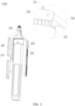
FIG. 1 is a first schematic diagram of the three-dimensional structure of the shooting bracket in one embodiment of the present application, in which the auxiliary handle and the clamping device are in a folded state; -
FIG. 2 is a second schematic diagram of the three-dimensional structure of the shooting bracket in one embodiment of the present application, in which the auxiliary handle and the clamping device are in an unfolded state; -
FIG. 3 is a cross-sectional schematic diagram of the shooting bracket inFIG. 1 ; -
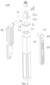
FIG. 4 is an exploded structural schematic diagram of the shooting bracket inFIG. 1 ; -
FIG. 5 is a schematic diagram of the three-dimensional structure of the auxiliary handle inFIG. 4 ; -
FIG. 6 is a schematic diagram of the three-dimensional structure of the gear inFIG. 4 ; -
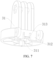
Fig. 7 is a schematic diagram of the three-dimensional structure of the connection frame inFig. 4 . - The numbers in the drawings are as follows:
- 100. Shooting bracket;
- 10. Bracket body; 11. Plug-in hole; 12. Limiting hole;
- 20. First limiting part/gear; 21. Gear body; 22. Plug-in shaft; 23. Limiting protrusion; 24. Rotating connection groove;
- 30. Connection device; 31. Connection frame; 311. Rotating connection piece; 312. Opening; 313. Snap-fit buckle;
- 40. Clamping device;
- 50. Auxiliary handle; 51. Hinged end; 511. Snap-fit slot; 52. Second limit part/connection rack;
- 60. Remote controller.
- Unless otherwise defined, all technical and scientific terms used herein have the same meanings as commonly understood by those skilled in the technical field of the present application; the terms used in the specification are only for the purpose of describing specific embodiments and are not intended to limit the present application, for example, the directions or positions indicated by the terms "length", "width", "upper", "lower", "left", "right", "front", "back", "vertical", "horizontal", "top", "bottom", "inside", "outside", etc. are based on the directions or positions shown in the drawings. They are only for convenience of description and cannot be understood as limitations of the present technical solution.
- The terms "include" and "having" and any variations thereof in the description and claims of the present application and the description of the above drawings are intended to cover non-exclusive inclusion. The terms "first", "second", etc. in the description and claims of the present application or the above drawings are used to distinguish different objects and are not used to describe a specific order. "Plural" means two or more, unless otherwise expressly and specifically limited.
- In the description and claims of the present application, as well as the above description of the drawings, when an element is referred to as being "fixed to" or "mounted on" or "disposed on" or "connected to" another element, it can be directly or indirectly located on the other element. For example, when an element is referred to as being "connected to" another element, it can be directly or indirectly connected to the other element.
- Furthermore, reference herein to "an embodiment" means that a particular feature, structure or characteristic described in connection with the embodiment can be included in at least one embodiment of the present application. The appearances of this phrase in various places in the description are not necessarily all referring to the same embodiment, nor are separate or alternative embodiments mutually exclusive of other embodiments. Those skilled in the art understand, both explicitly and implicitly, that the embodiments described herein may be combined with other embodiments.
- An embodiment of the present application provides a
shooting bracket 100, which is used to support a shooting equipment (not shown). Wherein, the shooting equipment includes mobile phones, tablets and other electronic products. In addition, theshooting bracket 100 can be used handheld, or can be unfolded and placed on a support platform (not shown), or can be directly fixed and mounted at a target location. - As shown in
FIGS. 1 to 4 , theshooting bracket 100 includes abracket body 10, aconnection device 30, aclamping device 40 and anauxiliary handle 50 for the user to hold. Wherein, thebracket body 10 is a support component of theshooting bracket 100, which can be used for the user to hold, and can also be used to support theentire shooting bracket 100 on a support platform (specifically, the ground, a workbench, etc.). - In addition, in order to adjust the shooting angle of the shooting equipment, the
connection device 30 is mounted on thebracket body 10 and can rotate around the extension direction of the bracket body 10 (specifically, the axial direction of the bracket body 10). The clampingdevice 40 is rotatably mounted on theconnection device 30 to clamp the shooting equipment. Preferably, the clampingdevice 40 is hingedly connected to theconnection device 30. - It can be understood that when it is necessary to adjust the shooting angle of the shooting device, the user only needs to rotate the
connection device 30 and theclamping device 40 to adjust the angle of the shooting device, thereby meeting the user's shooting needs. - It should be noted that in this embodiment, the rotation axis of the
connection device 30 around thebracket body 10 and the rotation axis of theclamping device 40 around theconnection device 30 are perpendicular to each other, so that theclamping device 40 has greater rotational freedom. - It should also be noted that the
clamping device 40 can be an existing structure or an innovative structure, as long as it can clamp the shooting equipment, and the present application does not limit this. - In addition, in order to improve the stability of the movement of the shooting equipment during movement, the
auxiliary handle 50 has a hingedend 51, and theauxiliary handle 50 is rotatably mounted on theconnection device 30 through the hingedend 51 so that theauxiliary handle 50 can perform pitching motions relative to thebracket body 10. It can be understood that during the mobile shooting process, the user can hold and rotate theauxiliary handle 50, theauxiliary handle 50 drives theconnection device 30 to rotate, and theconnection device 30 drives theclamping device 40 to rotate, thereby driving the shooting equipment on theclamping device 40 to rotate to adjust the shooting angle and position of the shooting device during movement. - Using the above technical solution, the user can hold the
auxiliary handle 50 for shooting during movement to reduce the shaking of the shooting equipment, thereby improving the use stability of theshooting bracket 100 and thus improving the shooting quality of the shooting equipment. In addition, theauxiliary handle 50 is rotatably mounted on theconnection device 30, so that the position of theauxiliary handle 50 itself can be changed, which facilitates folding and storage of theauxiliary handle 50, or changing the extension angle of the user's hand and arm, thereby improving the user's use experience. - As shown in
FIGS. 1 and4 , one of thebracket body 10 and theauxiliary handle 50 is provided with a first limitingpart 20, and the other is provided with a second limitingpart 52 matched with the first limitingpart 20. When theauxiliary handle 50 is in a folded state (specifically, theauxiliary handle 50 is folded on the bracket body 10), by meshing of the first limitingpart 20 and the second limitingpart 52, the relative rotation is prevented between theauxiliary handle 50 and thebracket body 10. - To sum up, compared with the prior art, the
shooting bracket 100 at least has the following beneficial effects:
theshooting bracket 100 is provided with the first limitingpart 20 and the second limitingpart 52 meshed with each other, so that when theauxiliary handle 50 is folded on thebracket body 10, the position of theauxiliary handle 50 is limited, thereby realizing the locking of theauxiliary handle 50 in the folded state, preventing relative rotation or shaking between theauxiliary handle 50 and thebracket body 10, thereby ensuring that theconnection device 30 connected to theauxiliary handle 50 is not affected by theauxiliary handle 50, but always maintains a static state stably. - Therefore, the clamping
device 40 connected to theconnection device 30 can be prevented from rotating or shaking, that is, the shooting equipment clamped on theclamping device 40 can be prevented from rotating or shaking, thereby improving the use stability of theshooting bracket 100 and improving the shooting effect of the shooting equipment. - In order to enable those skilled in the art to better understand the solution of the present application, the technical solution in the embodiment of the present application will be clearly and completely described below with reference to the accompanying drawings 1 to 7.
- Further, as a specific implementation in some embodiments of the present application, as shown in
FIGS. 1 and4 , agear 20 is provided on the top of thebracket body 10 to form the first limitingpart 20, and aconnection rack 52 matched with thegear 20 is provided at a position of theauxiliary handle 50 near the hingedend 51 to form the second limitingpart 52. When theauxiliary handle 50 is in the folded state, theauxiliary handle 50 is locked on thebracket body 10 through the mutual meshing between theconnection rack 52 and thegear 20, thereby restricting theclamping device 40 connected to theconnection device 30 from rotating around the extension direction of thebracket body 10. - It can be understood that when the
auxiliary handle 50 is in the folded state, the user can hold thebracket body 10 and theauxiliary handle 50 to take pictures. Wherein, since theconnection rack 52 and thegear 20 are in a meshing state, theconnection device 30 is restricted from rotating around the extending direction of thebracket body 10. That is, the clampingdevice 40 is restricted from rotating around the extending direction of thebracket body 10, thereby realizing that theauxiliary handle 50 is locked in the folded state to avoid the problem that when theshooting bracket 100 is used with theauxiliary handle 50 being folded, the clampingdevice 40 rotates or shakes, affecting the shooting effect. - Of course, in other embodiments, the
gear 20 can also be disposed on theauxiliary handle 50, theconnection rack 52 can be disposed on the top of thebracket body 10, and the first limitingpart 20 and the second limitingpart 52 can also be other structures that can be meshed with each other to plays a position-limiting role, the present application does not limit this, and those skilled in the art can choose according to the actual situation. - Further, as a specific implementation of the
shooting bracket 100 provided by the present application, as shown inFIGS. 3 and4 , in order to facilitate the installation and positioning of thegear 20, thegear 20 includes agear body 21 with gear teeth and a plug-inshaft 22 axially provided on one side of thegear body 21. Between theconnection device 30 and thebracket body 10, thegear 20 is rotatably connected to theconnection device 30, and is plugged into the top of thebracket body 10 through the plug-inshaft 22. - In detail, the
gear body 21 is provided with a plug-inshaft 22 on one side facing thebracket body 10. The top of thebracket body 10 is provided with a plug-inhole 11 that matches the plug-inshaft 22. When thegear 20 needs to be mounted, operate personnel only need to plug the plug-inshaft 22 into the plug-inhole 11 to mount thegear 20 on the top of thebracket body 10. - It should be noted that by using the positioning and installation method of the plug-in
shaft 22 and the plug-inhole 11, firstly, thegear 20 can be quickly positioned and installed, thereby greatly improving the production efficiency of the product; secondly, the installation offset of thegear 20 can be avoided. The offset will cause the problem of motion interference between theauxiliary handle 50 and thegear 20 during the folding process. - Further, as a specific implementation of the
shooting bracket 100 provided by the present application, as shown inFIGS. 3 ,4 and6 , a limiting structure is provided between thegear body 21 and thebracket body 10, and the limiting structure includes a limitingprotrusion 23 and a limitinghole 12 matched with the limitingprotrusion 23. Wherein, one of thegear body 21 and thebracket body 10 is provided with the limitingprotrusion 23, and the other is provided with the limitinghole 12. When thegear 20 is plugged into thebracket body 10, the limitingprotrusion 23 extends into the limitinghole 12 to limit the rotation ofgear 20. - In this embodiment, two limiting
protrusions 23 are provided on the side of thegear body 21 facing thebracket body 10, and the two limitingprotrusions 23 are arranged symmetrically along the center of thegear 20, and limitingholes 12 are arranged at corresponding positions of the top of thebracket body 10. When thegear 20 is plugged into thebracket body 10, each limitingprotrusion 23 extends into the corresponding limitinghole 12 to limit the rotation of thegear 20. - It can be understood that when the
auxiliary handle 50 is folded on thebracket body 10, theconnection rack 52 and the gear teeth on thegear body 21 of thegear 20 are meshed with each other. When the user moves theshooting bracket 100, theauxiliary handle 50 is acted upon by an external force and will have a tendency to rotate, but due to the meshing between the limitingprotrusion 23 and the limitinghole 12, the rotation of thegear 20 is restricted, making thegear 20 limit the rotation of theauxiliary handle 50 to ensure that theauxiliary handle 50 in theshooting bracket 100 is always in a locked state, thereby preventing relative rotation or shaking between theauxiliary handle 50 and thebracket body 10, thereby improving the use stability of theshooting bracket 100. - Of course, in other embodiments, the limiting
protrusion 23 can also be provided on the top of thebracket body 10, and the limitinghole 12 is provided on the side of thegear body 21 facing thebracket body 10. The number of the limitingprotrusions 23 and the limitingholes 12 can also be 4, 6 or other numbers. The present application does not limit this, and those skilled in the art can choose according to the actual situation. - In this embodiment, as shown in
FIGS. 3 ,4 and7 , theconnection device 30 includes aconnection frame 31. Theconnection frame 31 is rotatably mounted on the side of thegear 20 away from thebracket body 10, and is rotatably connected to theclamping device 40. Specifically, thegear body 21 of thegear 20 is provided with a boss (not shown) on one side close to theconnection frame 31. Arotating connection groove 24 is recessed on the boss, and theconnection frame 31 is provided with arotating connection piece 311. Therotating connection piece 311 is plugged into therotating connection groove 24 to realize the rotating connection between theconnection frame 31 and thegear 20. - In addition, the
auxiliary handle 50 is rotatably mounted on theconnection frame 31, and the rotation axis of theauxiliary handle 50 around theconnection frame 31 is perpendicular to the rotation axis of theconnection frame 31 around thebracket body 10, so that theauxiliary handle 50 can be rotated and folded on thebracket body 10, that is, in a folded state; or theauxiliary handle 50 can be rotated and unfolded relative to thebracket body 10 for the user to hold. - In detail, the
connection device 30 also includes a latch (not shown). Anopening 312 is provided on the peripheral side of theconnection frame 31. The hingedend 51 of theauxiliary handle 50 is plugged into theopening 312. The latch passes through theconnection frame 31 and theauxiliary handle 50 in turn, so that theauxiliary handle 50 is rotatably connected to theconnection frame 31. - It can be understood that when it is necessary to use the
auxiliary handle 50, the user rotates theauxiliary handle 50 in a direction away from thebracket body 10, and theauxiliary handle 50 ca be unfolded relative to thebracket body 10 with the central axis of the latch as the rotation axis for the user to hold. When theauxiliary handle 50 is not in use, the user rotates theauxiliary handle 50 in a direction close to thebracket body 10, and theauxiliary handle 50 can be rotated and folded on thebracket body 10 with the central axis of the latch as the rotation axis, that is, in a folded state. - Further, as a specific implementation of the
shooting bracket 100 provided by the present application, as shown inFIGS. 4 ,5 and7 , in order to avoid the problem of theauxiliary handle 50 swinging up and down after being folded, in theopening 312, a snap-fit structure is provided between theconnection frame 31 and the hingedend 51. Wherein, the snap-fit structure includes a snap-fit buckle 313 and a snap-fit slot 511 that matches the snap-fit buckle 313. One of theconnection frame 31 and the hingedend 51 is provided with the snap-fit buckle 313, and the other is provided with the snap-fit slot 511. When theauxiliary handle 50 is in the folded state, the snap-fit buckle 313 is locked in the snap-fit slot 511. - In this embodiment, the
connection frame 31 is provided with the snap-fit buckle 313 in theopening 312, and the hingedend 51 of theauxiliary handle 50 is provided with the snap-fit slot 511. When theauxiliary handle 50 is in a folded state, the snap-fit buckle 313 is meshed with the snap-fit slot 511 to limit the position of theauxiliary handle 50, thereby avoiding the problem that theauxiliary handle 50 swings up and down and reduces the stability of theshooting bracket 100 when it is folded and not in use. - Of course, in other embodiments, the snap-
fit buckle 313 can also be provided on the hingedend 51 of theauxiliary handle 50, and the snap-fit slot 511 is provided in theopening 312 of theconnection frame 31. The present application does not limit this. Those skilled in the art can choose according to actual situation. - Furthermore, as a specific implementation of the
shooting bracket 100 provided by the present application, theshooting bracket 100 also includes a plurality of support legs (not shown), each of which is rotatably mounted on thebracket body 10 to unfold relative to the bracket or fold on thebracket body 10. Preferably, each support leg is hingedly connected to thebracket body 10. - It can be understood that when the
shooting bracket 100 needs to be supported on the support platform, the user exerts a force on the support leg, causing the support leg to rotate in a direction away from thebracket body 10 with its hinged end as the center to be unfold and supported on the support platform. When it is necessary to hold theshooting bracket 100 to shoot, the user exerts a force opposite to the above on the support leg, causing the support leg to rotate in a direction close to thebracket body 10 with its hinged end as the center, so as to be folded on thebracket body 10, and together with thebracket body 10 to form a handle. - Therefore, firstly, after the support legs are unfolded, the
shooting bracket 100 can be stably supported on the support platform, improving the stability of shooting; secondly, after the support legs are folded, thebracket body 10 can be turned into a handle for the user to hold and use, or store conveniently, reducing the space occupied. - Further, as a specific implementation of the
shooting bracket 100 provided by the present application, as shown inFIGS. 1 and2 , in order to remotely control the shooting equipment to take pictures, theshooting bracket 100 also includes aremote controller 60 for controlling the shooting equipment, theremote controller 60 is detachably mounted on theauxiliary handle 50. Specifically, in this embodiment, a storage slot (not shown) is provided on theauxiliary handle 50, and theremote controller 60 is detachably connected to theauxiliary handle 50 in the storage slot through a magnetic attraction structure (not shown). Of course, in other embodiments, other detachable structures such as bonding can also be used. The present application does not limit this, and those skilled in the art can choose according to actual situation. - It should be noted that when the user performs handheld shooting, the
remote controller 60 is placed in the storage slot, and the control buttons of theremote controller 60 are exposed to the opening position of the storage slot, thereby facilitating the control of shooting. When the user places theshooting bracket 100 on the support platform, the user can take out theremote controller 60 from the storage slot, thereby enabling remote control of the electronic device for taking pictures. - The above descriptions are only preferred embodiments of the present application and are not intended to limit the present application. For those skilled in the art, various modifications and changes may be made to the present application. Any modifications, equivalent substitutions, improvements, etc. made within the spirit and principles of the present application shall be included in the scope of the claims of the present application.
Claims (10)
- A shooting bracket, wherein the shooting bracket includes:a bracket body, a connection device, a clamping device and an auxiliary handle with a hinged end;the connection device is mounted on the bracket body and is rotatable around an extension direction of the bracket body;the clamping device is rotatably mounted on the connection device;the hinged end of the auxiliary handle is rotatably mounted on the connection device, so that the auxiliary handle can perform pitching motion relative to the bracket body;wherein, one of the bracket body and the auxiliary handle is provided with a first limiting part, and the other is provided with a second limiting part matched with the first limiting part; when the auxiliary handle is in a folded state, through meshing of the first limiting part and the second limiting part, relative rotation between the auxiliary handle and the bracket body is prevented.
- The shooting bracket according to claim 1, wherein a gear is provided on the top of the bracket body to form the first limiting part; a connection rack that matches the gear is provided at a position of the auxiliary handle near the hinged end to form the second limiting part;
when the auxiliary handle is in a folded state, the auxiliary handle is locked on the bracket body through the mutual meshing between the connection rack and the gear. - The shooting bracket according to claim 2, wherein the gear includes a gear body with gear teeth and a plug-in shaft axially disposed on one side of the gear body; between the connection device and the bracket body, the gear is rotatably connected to the connection device and plugged into the top of the bracket body through the plug-in shaft.
- The shooting bracket according to claim 3, wherein a limiting structure is provided between the gear body and the bracket body, and the limiting structure includes a limiting protrusion and a limiting hole;
wherein, one of the gear body and the bracket body is provided with the limiting protrusion, and the other is provided with the limiting hole; when the gear is plugged into the bracket body, the limiting protrusion extends into the limiting hole to limit rotation of the gear. - The shooting bracket according to claim 4, wherein the number of the limiting protrusions is two, and the two limiting protrusions are provided on a side of the gear body facing the bracket body and arranged symmetrically along the center of the gear.
- The shooting bracket according to any one of claims 2 to 5, wherein the connection device includes a connection frame, the connection frame is rotatably mounted on a side of the gear away from the bracket body, and is rotatably connected with the clamping device;
the auxiliary handle is rotatably mounted on the connection frame, and a rotation axis of the auxiliary handle around the connection frame is perpendicular to a rotation axis of the connection frame around the bracket body. - The shooting bracket according to claim 6, wherein the connection device further includes a latch, an opening is provided on a peripheral side of the connection frame, and the hinged end of the auxiliary handle is plugged into the opening, the latch passes through the connection frame and the auxiliary handle in turn, so that the auxiliary handle is rotatably connected to the connection frame.
- The shooting bracket according to claim 7, wherein in the opening, a snap-fit structure is provided between the connection frame and the hinged end; the snap-fit structure includes a snap-fit buckle and a snap-fit slot matched with the snap-fit buckle, one of the connection frame and the hinged end is provided with the snap-fit buckle, and the other is provided with the snap-fit slot; when the auxiliary handle is in a folded state, the snap-fit buckle is snapped in the snap-fit slot.
- The shooting bracket according to claim 1, wherein the shooting bracket further includes a plurality of support legs, each of the support legs is rotatably mounted on the bracket body to unfold relative to the bracket body, or fold on the bracket body.
- The shooting bracket according to claim 1, wherein the shooting bracket further includes a remote controller for controlling a shooting equipment, and the remote controller is detachably mounted on the auxiliary handle.
Applications Claiming Priority (1)
| Application Number | Priority Date | Filing Date | Title |
|---|---|---|---|
| CN202320551267.4U CN219433022U (en) | 2023-03-13 | 2023-03-13 | Shooting support |
Publications (1)
| Publication Number | Publication Date |
|---|---|
| EP4431786A1 true EP4431786A1 (en) | 2024-09-18 |
Family
ID=87336249
Family Applications (1)
| Application Number | Title | Priority Date | Filing Date |
|---|---|---|---|
| EP23215707.3A Withdrawn EP4431786A1 (en) | 2023-03-13 | 2023-12-12 | Shooting bracket |
Country Status (4)
| Country | Link |
|---|---|
| US (1) | US12158234B2 (en) |
| EP (1) | EP4431786A1 (en) |
| JP (1) | JP2024129782A (en) |
| CN (1) | CN219433022U (en) |
Families Citing this family (2)
| Publication number | Priority date | Publication date | Assignee | Title |
|---|---|---|---|---|
| US12669743B2 (en) | 2024-08-05 | 2026-06-30 | Shenzhen Haohualianhe Technology Co., Ltd. | Multi-legged stand and electronic terminal support device |
| WO2026032308A1 (en) * | 2024-08-05 | 2026-02-12 | 深圳市豪华联合科技有限公司 | Multi-foot support |
Citations (1)
| Publication number | Priority date | Publication date | Assignee | Title |
|---|---|---|---|---|
| EP4083490A1 (en) * | 2020-01-20 | 2022-11-02 | Shenzhen Diepin Technology Co., Ltd. | Photographing device support having auxiliary handle |
Family Cites Families (6)
| Publication number | Priority date | Publication date | Assignee | Title |
|---|---|---|---|---|
| JP6639643B2 (en) * | 2015-08-10 | 2020-02-05 | エスゼット ディージェイアイ オスモ テクノロジー カンパニー リミテッドSZ DJI Osmo Technology Co., Ltd. | Clamping structure and cloud base having the clamping structure |
| CN108930900A (en) * | 2018-08-21 | 2018-12-04 | 桂林智神信息技术有限公司 | A kind of light-duty hand-held stabilizer |
| GB2578637B (en) * | 2018-11-02 | 2022-09-14 | Jolley Richard | Camera support |
| CN209511452U (en) | 2018-11-19 | 2019-10-18 | 源德盛塑胶电子(深圳)有限公司 | a selfie device |
| CN209725636U (en) * | 2018-11-19 | 2019-12-03 | 源德盛塑胶电子(深圳)有限公司 | A kind of clamping device |
| CN210034983U (en) | 2019-02-15 | 2020-02-07 | 深圳市全天拍科技有限公司 | multifunctional selfie stick |
-
2023
- 2023-03-13 CN CN202320551267.4U patent/CN219433022U/en active Active
- 2023-11-17 JP JP2023195837A patent/JP2024129782A/en not_active Ceased
- 2023-12-07 US US18/533,151 patent/US12158234B2/en active Active
- 2023-12-12 EP EP23215707.3A patent/EP4431786A1/en not_active Withdrawn
Patent Citations (1)
| Publication number | Priority date | Publication date | Assignee | Title |
|---|---|---|---|---|
| EP4083490A1 (en) * | 2020-01-20 | 2022-11-02 | Shenzhen Diepin Technology Co., Ltd. | Photographing device support having auxiliary handle |
Also Published As
| Publication number | Publication date |
|---|---|
| JP2024129782A (en) | 2024-09-27 |
| US12158234B2 (en) | 2024-12-03 |
| CN219433022U (en) | 2023-07-28 |
| US20240309988A1 (en) | 2024-09-19 |
Similar Documents
| Publication | Publication Date | Title |
|---|---|---|
| US12158234B2 (en) | Shooting bracket | |
| CN212251923U (en) | Shooting equipment support with auxiliary handle | |
| CN108980587A (en) | Hand-held holder | |
| WO2018132990A1 (en) | Camera mount assembly, and hand-held camera mount-based image capturer | |
| US12292068B2 (en) | Mobile phone bracket | |
| WO2019023854A1 (en) | Gimbal photographing device | |
| KR20190127960A (en) | Gimbal camera | |
| CN112923198A (en) | Hand-held cloud platform | |
| CN109551922A (en) | Leaf turner and the method that the bracket of setting photographic device is fixed | |
| WO2015021695A1 (en) | Packable folding camera apparatus | |
| WO2019023860A1 (en) | PTZ camera | |
| CN207337039U (en) | Holder device for shooting | |
| CN111699339B (en) | Hand-held cloud platform | |
| CN107571253A (en) | It is a kind of can own rotation and keep level balance robotic arm | |
| CN207637997U (en) | A kind of antenna assembly and the remote controler with the antenna assembly, unmanned thermomechanical components | |
| CN212411102U (en) | Electronic equipment | |
| CN222392523U (en) | A support movement mechanism | |
| CN218662421U (en) | A rotatory lift cloud platform for unmanned aerial vehicle carries | |
| CN210344941U (en) | Hand-held cloud platform | |
| CN209744010U (en) | hand-held cloud platform | |
| CN209294752U (en) | Holder hand held structures and hand-held holder | |
| CN209725667U (en) | Connection components and PTZ equipment | |
| CN219433023U (en) | An auxiliary handle and a selfie stick | |
| CN222068090U (en) | Auxiliary shooting support | |
| CN217603822U (en) | Cloud platform and shooting auxiliary assembly |
Legal Events
| Date | Code | Title | Description |
|---|---|---|---|
| PUAI | Public reference made under article 153(3) epc to a published international application that has entered the european phase |
Free format text: ORIGINAL CODE: 0009012 |
|
| STAA | Information on the status of an ep patent application or granted ep patent |
Free format text: STATUS: REQUEST FOR EXAMINATION WAS MADE |
|
| 17P | Request for examination filed |
Effective date: 20231212 |
|
| AK | Designated contracting states |
Kind code of ref document: A1 Designated state(s): AL AT BE BG CH CY CZ DE DK EE ES FI FR GB GR HR HU IE IS IT LI LT LU LV MC ME MK MT NL NO PL PT RO RS SE SI SK SM TR |
|
| STAA | Information on the status of an ep patent application or granted ep patent |
Free format text: STATUS: THE APPLICATION HAS BEEN WITHDRAWN |
|
| 18W | Application withdrawn |
Effective date: 20250314 |