EP4431769A1 - Five-way valve - Google Patents
Five-way valve Download PDFInfo
- Publication number
- EP4431769A1 EP4431769A1 EP22902726.3A EP22902726A EP4431769A1 EP 4431769 A1 EP4431769 A1 EP 4431769A1 EP 22902726 A EP22902726 A EP 22902726A EP 4431769 A1 EP4431769 A1 EP 4431769A1
- Authority
- EP
- European Patent Office
- Prior art keywords
- cavity
- outlet
- valve
- fan
- shaped
- Prior art date
- Legal status (The legal status is an assumption and is not a legal conclusion. Google has not performed a legal analysis and makes no representation as to the accuracy of the status listed.)
- Pending
Links
Images






Classifications
-
- F—MECHANICAL ENGINEERING; LIGHTING; HEATING; WEAPONS; BLASTING
- F16—ENGINEERING ELEMENTS AND UNITS; GENERAL MEASURES FOR PRODUCING AND MAINTAINING EFFECTIVE FUNCTIONING OF MACHINES OR INSTALLATIONS; THERMAL INSULATION IN GENERAL
- F16K—VALVES; TAPS; COCKS; ACTUATING-FLOATS; DEVICES FOR VENTING OR AERATING
- F16K11/00—Multiple-way valves, e.g. mixing valves; Pipe fittings incorporating such valves
- F16K11/02—Multiple-way valves, e.g. mixing valves; Pipe fittings incorporating such valves with all movable sealing faces moving as one unit
- F16K11/08—Multiple-way valves, e.g. mixing valves; Pipe fittings incorporating such valves with all movable sealing faces moving as one unit comprising only taps or cocks
- F16K11/085—Multiple-way valves, e.g. mixing valves; Pipe fittings incorporating such valves with all movable sealing faces moving as one unit comprising only taps or cocks with cylindrical plug
-
- F—MECHANICAL ENGINEERING; LIGHTING; HEATING; WEAPONS; BLASTING
- F16—ENGINEERING ELEMENTS AND UNITS; GENERAL MEASURES FOR PRODUCING AND MAINTAINING EFFECTIVE FUNCTIONING OF MACHINES OR INSTALLATIONS; THERMAL INSULATION IN GENERAL
- F16K—VALVES; TAPS; COCKS; ACTUATING-FLOATS; DEVICES FOR VENTING OR AERATING
- F16K11/00—Multiple-way valves, e.g. mixing valves; Pipe fittings incorporating such valves
- F16K11/02—Multiple-way valves, e.g. mixing valves; Pipe fittings incorporating such valves with all movable sealing faces moving as one unit
- F16K11/08—Multiple-way valves, e.g. mixing valves; Pipe fittings incorporating such valves with all movable sealing faces moving as one unit comprising only taps or cocks
- F16K11/085—Multiple-way valves, e.g. mixing valves; Pipe fittings incorporating such valves with all movable sealing faces moving as one unit comprising only taps or cocks with cylindrical plug
- F16K11/0856—Multiple-way valves, e.g. mixing valves; Pipe fittings incorporating such valves with all movable sealing faces moving as one unit comprising only taps or cocks with cylindrical plug having all the connecting conduits situated in more than one plane perpendicular to the axis of the plug
-
- F—MECHANICAL ENGINEERING; LIGHTING; HEATING; WEAPONS; BLASTING
- F16—ENGINEERING ELEMENTS AND UNITS; GENERAL MEASURES FOR PRODUCING AND MAINTAINING EFFECTIVE FUNCTIONING OF MACHINES OR INSTALLATIONS; THERMAL INSULATION IN GENERAL
- F16K—VALVES; TAPS; COCKS; ACTUATING-FLOATS; DEVICES FOR VENTING OR AERATING
- F16K27/00—Construction of housing; Use of materials therefor
- F16K27/06—Construction of housing; Use of materials therefor of taps or cocks
- F16K27/065—Construction of housing; Use of materials therefor of taps or cocks with cylindrical plugs
-
- F—MECHANICAL ENGINEERING; LIGHTING; HEATING; WEAPONS; BLASTING
- F16—ENGINEERING ELEMENTS AND UNITS; GENERAL MEASURES FOR PRODUCING AND MAINTAINING EFFECTIVE FUNCTIONING OF MACHINES OR INSTALLATIONS; THERMAL INSULATION IN GENERAL
- F16K—VALVES; TAPS; COCKS; ACTUATING-FLOATS; DEVICES FOR VENTING OR AERATING
- F16K31/00—Actuating devices; Operating means; Releasing devices
- F16K31/02—Actuating devices; Operating means; Releasing devices electric; magnetic
- F16K31/04—Actuating devices; Operating means; Releasing devices electric; magnetic using a motor
- F16K31/041—Actuating devices; Operating means; Releasing devices electric; magnetic using a motor for rotating valves
-
- F—MECHANICAL ENGINEERING; LIGHTING; HEATING; WEAPONS; BLASTING
- F16—ENGINEERING ELEMENTS AND UNITS; GENERAL MEASURES FOR PRODUCING AND MAINTAINING EFFECTIVE FUNCTIONING OF MACHINES OR INSTALLATIONS; THERMAL INSULATION IN GENERAL
- F16K—VALVES; TAPS; COCKS; ACTUATING-FLOATS; DEVICES FOR VENTING OR AERATING
- F16K31/00—Actuating devices; Operating means; Releasing devices
- F16K31/44—Mechanical actuating means
- F16K31/53—Mechanical actuating means with toothed gearing
-
- F—MECHANICAL ENGINEERING; LIGHTING; HEATING; WEAPONS; BLASTING
- F16—ENGINEERING ELEMENTS AND UNITS; GENERAL MEASURES FOR PRODUCING AND MAINTAINING EFFECTIVE FUNCTIONING OF MACHINES OR INSTALLATIONS; THERMAL INSULATION IN GENERAL
- F16K—VALVES; TAPS; COCKS; ACTUATING-FLOATS; DEVICES FOR VENTING OR AERATING
- F16K31/00—Actuating devices; Operating means; Releasing devices
- F16K31/44—Mechanical actuating means
- F16K31/53—Mechanical actuating means with toothed gearing
- F16K31/535—Mechanical actuating means with toothed gearing for rotating valves
Definitions
- the present disclosure relates to the technical field of five-way valves, specifically to a five-way valve.
- the five-way valve in the prior art usually uses two valve cores and two motors, and the two motors respectively drive the two valve cores to rotate.
- the switching between multiple working conditions of the five-way valve and the flow rate adjustment can be achieved by rotation of the valve core.
- the five-way valve in the prior art requires two valve cores and two motors to achieve working condition switching and flow rate adjusting functions, there are more structures, the production and manufacturing difficulty is higher, the mounting accuracy is difficult to ensure during a mounting process, and the cost is high.
- Some embodiments of the present disclosure provide a five-way valve to solve the problem of high manufacturing cost of five-way valves in the prior art.
- some embodiments of the present disclosure provide a five-way valve, including: a main body portion, the main body portion having a valve cavity, a first inlet, a second inlet, a first outlet, a second outlet, a third outlet, and a fourth outlet; a valve core rotatably arranged in the valve cavity, the valve core having a first cavity, a second cavity, a third cavity, and a fourth cavity which are separated; and a single-motor actuator, the single-motor actuator being in driving connection with the valve core, wherein the five-way valve can be switched to any one of the following working conditions by means of rotation of the valve core: a first working condition: the first inlet is communicated with the first outlet through the first cavity, the second inlet is communicated with the third outlet through the third cavity, and the second outlet and the fourth outlet are disconnected; a second working condition: the first inlet is communicated with the first outlet through the first cavity, the second inlet is communicated with both the third outlet and the fourth outlet through the
- the single-motor actuator is configured to drive the valve core to rotate and maintain at multiple different positions to adjust a proportion of fluids output from the third outlet and the fourth outlet; and in the fifth working condition, the single-motor actuator is configured to drive the valve core to rotate and maintain at multiple different positions to adjust a proportion of fluids output from the third outlet and the fourth outlet.
- the valve core includes a first axial region, a second axial region, and a third axial region which are sequentially arranged in an axial direction, and openings of the first cavity, the second cavity, the third cavity, and the fourth cavity all face an inner wall of the valve cavity; and the first cavity includes a first-first main cavity and a first-second main cavity which are communicated with each other, the third cavity includes a third-first main cavity and a third-second main cavity which are communicated with each other, the second cavity includes a second-first main cavity and a second-second main cavity which are communicated with each other, and the fourth cavity includes a fourth-first main cavity and a fourth-second main cavity which are communicated with each other, wherein the first-first main cavity and the second-first main cavity are both located in the first axial region, the first-second main cavity, the third-first main cavity, the fourth-first main cavity, and the second-second main cavity are all located in the second axial region, and the third-second main cavity and the fourth-second main cavity
- the valve core includes a first fan-shaped region, a second fan-shaped region, a third fan-shaped region, a fourth fan-shaped region, a fifth fan-shaped region, a sixth fan-shaped region, a seventh fan-shaped region, and an eighth fan-shaped region which are sequentially arranged in a circumferential direction, wherein the first-first main cavity is distributed in the first fan-shaped region and the second fan-shaped region, the first-second main cavity is distributed in the first fan-shaped region and the second fan-shaped region, the third-first main cavity is distributed in the third fan-shaped region and the fourth fan-shaped region, the third-second main cavity is distributed in the second fan-shaped region and the third fan-shaped region, the second-first main cavity is distributed in the seventh fan-shaped region and the eighth fan-shaped region, the second-second main cavity is distributed in the seventh fan-shaped region and the eighth fan-shaped region, the fourth-first main cavity is distributed in the fifth fan-shaped region and the sixth fan-shaped region, and the fourth-second main cavity is distributed
- first axial region, the second axial region, and the third axial region are equal; and in the circumferential direction of the valve core, radians of the first fan-shaped region, the second fan-shaped region, the third fan-shaped region, the fourth fan-shaped region, the fifth fan-shaped region, the sixth fan-shaped region, the seventh fan-shaped region, and the eighth fan-shaped region are equal.
- opening angles of the third outlet and the fourth outlet are both H1
- a spacing angle between the third outlet and the fourth outlet is H2
- opening angles of the third-second main cavity and the fourth-second main cavity are both H3, wherein H1 ⁇ H2 ⁇ H3.
- the valve core includes a shaft sleeve, two circular end plates, a plurality of axial partition plates, and a plurality of fan-shaped partition plates, the two circular end plates are arranged in parallel and are both fixedly connected with the shaft sleeve, and the two circular end plates and the shaft sleeve are both coaxially arranged, wherein the plurality of axial partition plates and the plurality of fan-shaped partition plates are distributed in a space between the two circular end plates to divide the space between the two circular end plates into the first cavity, the second cavity, the third cavity, and the fourth cavity, and the single-motor actuator is in driving connection with the shaft sleeve.
- each of the plurality of axial partition plates and each of the plurality of fan-shaped partition plates are both connected with the shaft sleeve, and the each of the plurality of fan-shaped partition plates is connected with at least two axial partition plates in the plurality of axial partition plates;
- the third-second main cavity includes a first sub-cavity and a second sub-cavity which are communicated with each other
- the fourth-second main cavity includes a third sub-cavity and a fourth sub-cavity which are communicated with each other
- the valve core further includes a first arc-shaped plate and a second arc-shaped plate; in the circumferential direction of the valve core, the first arc-shaped plate, the first sub-cavity, the second sub-cavity, the second arc-shaped plate, the third sub-cavity, and the fourth sub-cavity are sequentially arranged; in the first working condition, the first sub-cavity is connected to the third outlet, and the second arc-shaped plate blocks the fourth
- a bottom wall of the valve cavity is provided with an arc-shaped groove, the arc-shaped groove is arranged around an axis of the valve core, the five-way valve further includes a limiting block, the limiting block is located on a side of the valve core facing the bottom wall of the valve cavity, and the limiting block is located in the arc-shaped groove.
- the arc-shaped groove has a first arc-shaped wall, a second arc-shaped wall, a first end wall, and a second end wall
- the limiting block has a fan-shaped structure
- the limiting block has a third arc-shaped wall, a fourth arc-shaped wall, a third end wall, and a fourth end wall, wherein the first arc-shaped wall is matched with the third arc-shaped wall, the second arc-shaped wall is matched with the fourth arc-shaped wall, the first end wall is in stop fit with the third end wall, and the second end wall is in stop fit with the fourth end wall.
- the valve core has a first setting position and a second setting position; in a case that the valve core is located in the first setting position, the five-way valve is in the first working condition, and the first end wall is separated from the third end wall; in a case that the valve core is located in the second setting position, the five-way valve is in the sixth working condition, and the second end wall is separated from the fourth end wall; and in a case that the five-way valve is switched from the first working condition to the sixth working condition along a rotation direction, a rotation angle of the valve core is N, and a range of a rotation angle of the limiting block in the arc-shaped groove is greater than N.
- the valve core has a first setting position; in a case that the valve core is located in the first setting position, the five-way valve is in the first working condition, and the valve core has a reserved rotation angle M; in a case that the valve core rotates in a range of the rotation angle M along a rotation direction from the first setting position, the five-way valve is maintained in the first working condition; and in a case that the valve core rotates in a range greater than the rotation angle M along the rotation direction from the first setting position, the five-way valve is switched to other working conditions.
- the main body portion includes a valve body and a sealing gasket
- the valve body has the valve cavity
- the sealing gasket is arranged in the valve cavity
- the first inlet, the second inlet, the first outlet, the second outlet, the third outlet, and the fourth outlet are all arranged in the sealing gasket
- the first outlet, the first inlet, and the third outlet are arranged along an axial direction of the valve core
- the second outlet, the second inlet, and the fourth outlet are arranged along the axial direction of the valve core
- the first outlet and the second outlet are arranged along the circumferential direction of the valve core
- the first inlet and the second inlet are arranged along the circumferential direction of the valve core
- the third outlet and the fourth outlet are arranged along the circumferential direction of the valve core.
- the sealing gasket has an arc-shaped structure, an outer side of the sealing gasket is attached to an inner wall of the valve cavity, an inner side of the sealing gasket is attached to an outer circumferential surface of the valve core, the main body portion further includes two arc-shaped baffle plates arranged on the inner wall of the valve cavity, and the two arc-shaped baffle plates respectively abut against two ends of the sealing gasket in a circumferential direction; and on a side of the sealing gasket facing the inner wall of the valve cavity, the sealing gasket is distributed with a plurality of sealing ribs in the axial direction and the circumferential direction.
- the valve body includes a base, a cylinder, and a plurality of reinforcing ribs
- the cylinder is connected with the base
- each of the plurality of reinforcing ribs is connected with both the base and an outer wall of the cylinder
- the cylinder has the valve cavity
- the base has six flow channels
- the six flow channels are respectively communicated with the first inlet, the second inlet, the first outlet, the second outlet, the third outlet, and the fourth outlet.
- the main body portion further includes a valve cover and a sealing ring, the valve cover is in sealed connection with the valve body, the valve cover blocks an opening of the valve cavity, the sealing ring is arranged in a groove of the valve cover, the five-way valve further includes a rotating shaft, a portion of the rotating shaft is fixed in the valve core, the rotating shaft passes through the sealing ring, and an output shaft of the single-motor actuator is in driving connection with the rotating shaft.
- the single-motor actuator includes a housing and a motor, a gear assembly, and a control plate which are arranged in the housing, the motor is in driving connection with an input shaft of the gear assembly, an output shaft of the gear assembly is in driving connection with the valve core, and the housing is fixedly connected with the main body portion.
- the technical solution of the present disclosure provides a five-way valve, including: a main body portion, the main body portion having a valve cavity, a first inlet, a second inlet, a first outlet, a second outlet, a third outlet, and a fourth outlet; a valve core rotatably arranged in the valve cavity, the valve core having a first cavity, a second cavity, a third cavity, and a fourth cavity which are separated; and a single-motor actuator, the single-motor actuator being in driving connection with the valve core, wherein the five-way valve can be switched to any one of the following working conditions by means of rotation of the valve core: a first working condition: the first inlet is communicated with the first outlet through the first cavity, the second inlet is communicated with the third outlet through the third cavity, and the second outlet and the fourth outlet are disconnected; a second working condition: the first inlet is communicated with the first outlet through the first cavity, the second inlet is communicated with both the third outlet and the fourth outlet through the third cavity, and the second outlet
- the switching between multiple working conditions of the five-way valve can be achieved by using one single-motor actuator to drive one valve core to rotate.
- this solution of the present disclosure reduces a set of single-motor actuator and valve core, thereby reducing the production and manufacturing difficulty of the five-way valve, improving the mounting accuracy of the overall structure of the five-way valve, and reducing the manufacturing cost of the five-way valve.
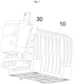
- an embodiment of the present disclosure provides a five-way valve, including: a main body portion 10, the main body portion 10 has a valve cavity 12, a first inlet 113, a second inlet 114, a first outlet 112, a second outlet 111, a third outlet 115, and a fourth outlet 116; a valve core 20 rotatably arranged in the valve cavity 12, the valve core 20 has a first cavity 21, a second cavity 22, a third cavity 23, and a fourth cavity 24 which are separated; and a single-motor actuator 30, the single-motor actuator 30 is in driving connection with the valve core 20, wherein the five-way valve can be switched to any one of the following working conditions by means of rotation of the valve core 20: a first working condition: the first inlet 113 is communicated with the first outlet 112 through the first cavity 21, the second inlet 114 is communicated with the third outlet 115 through the third cavity 23, and the second outlet 111 and the fourth outlet 116 are disconnected; a second working condition:
- the switching between multiple working conditions of the five-way valve can be achieved by using one single-motor actuator 30 to drive one valve core 20 to rotate.
- this solution reduces a set of motor and valve core 20, thereby reducing the production and manufacturing difficulty of the five-way valve, improving a mounting accuracy of the overall structure of the five-way valve, and reducing a manufacturing cost of the five-way valve.
- the single-motor actuator 30 in the second working condition, is able to drive the valve core 20 to rotate and maintain at multiple different positions to adjust the proportion of fluids output from the third outlet 115 and the fourth outlet 116; and in the fifth working condition, the single-motor actuator 30 is able to drive the valve core 20 to rotate and maintain at multiple different positions to adjust the proportion of fluids output from the third outlet 115 and the fourth outlet 116.
- a flow rate of the outlet of the five-way valve in the second working condition and the fifth working condition is adjusted by using one single-motor actuator 30 to drive one valve core 20 to rotate.
- this solution reduces a set of motor and valve core 20, thereby reducing the production and manufacturing difficulty and manufacturing cost of the five-way valve.
- the valve core 20 includes a first axial region 251, a second axial region 252, and a third axial region 253 which are sequentially arranged in an axial direction, and openings of the first cavity 21, the second cavity 22, the third cavity 23, and the fourth cavity 24 all face an inner wall of the valve cavity 12; and the first cavity 21 includes a first-first main cavity 211 and a first-second main cavity 212 which are communicated with each other, the third cavity 23 includes a third-first main cavity 231 and a third-second main cavity 232 which are communicated with each other, the second cavity 22 includes a second-first main cavity 221 and a second-second main cavity 222 which are communicated with each other, and the fourth cavity 24 includes a fourth-first main cavity 241 and a fourth-second main cavity 242 which are communicated with each other, wherein the first-first main cavity 211 and the second-first main cavity 221 are both located in the first axial region 251, the first-second main cavity
- a plurality of cavities for achieving a flow rate adjusting function and a working condition switching function of the five-way valve are arranged on the same valve core 20, that is, the valve core 20 is divided into three layers: the first axial region 251, the second axial region 252, and the third axial region 253, and the plurality of cavities with circulation relationships, namely the first cavity 21, the second cavity 22, the third cavity 23, and the fourth cavity 24, are limited on the first axial region 251, the second axial region 252, and the third axial region 253.
- this embodiment of the present disclosure combines the functions of two valve cores to form a new valve core 20, thereby reducing the production cost of the five-way valve.
- the valve core 20 includes a first fan-shaped region 261, a second fan-shaped region 262, a third fan-shaped region 263, a fourth fan-shaped region 264, a fifth fan-shaped region 265, a sixth fan-shaped region 266, a seventh fan-shaped region 267, and an eighth fan-shaped region 268 which are sequentially arranged in a circumferential direction, wherein the first-first main cavity 211 is distributed in the first fan-shaped region 261 and the second fan-shaped region 262, the first-second main cavity 212 is distributed in the first fan-shaped region 261 and the second fan-shaped region 262, the third-first main cavity 231 is distributed in the third fan-shaped region 263 and the fourth fan-shaped region 264, the third-second main cavity 232 is distributed in the second fan-shaped region 262 and the third fan-shaped region 263, the second-first main cavity 221 is distributed in the seventh fan-shaped region 267 and the eighth fan-shaped region 268, the second-second main main cavity 211 is distributed in the seventh fan-shaped region
- a plurality of cavities for achieving a flow rate adjusting function and a working condition switching function of the five-way valve are arranged on the same valve core 20, that is, the valve core 20 is divided into eight columns: the first fan-shaped region 261, the second fan-shaped region 262, the third fan-shaped region 263, the fourth fan-shaped region 264, the fifth fan-shaped region 265, the sixth fan-shaped region 266, the seventh fan-shaped region 267, and the eighth fan-shaped region 268, and the plurality of cavities with circulation relationships are limited in the plurality of fan-shaped regions.
- this embodiment combines the functions of two valve cores to form a new valve core 20, thereby reducing the production cost of the five-way valve.
- the lengths of the first axial region 251, the second axial region 252, and the third axial region 253 are equal; and in the circumferential direction of the valve core 20, the radians of the first fan-shaped region 261, the second fan-shaped region 262, the third fan-shaped region 263, the fourth fan-shaped region 264, the fifth fan-shaped region 265, the sixth fan-shaped region 266, the seventh fan-shaped region 267, and the eighth fan-shaped region 268 are equal.
- the communication areas between the cavity on each axial region and the inlet and outlet of the main body portion 10 are limited to be equal, thereby preventing the situation that the flow rates of the inlet and outlet of the five-way valve are different due to unequal communication areas between different axis regions and the inlet and outlet.
- the rotation angle of each fan-shaped region corresponding to the valve core 20 is ensured to be equal, thereby ensuring the rotation reliability of the valve core 20.
- the opening angles of the third outlet 115 and the fourth outlet 116 are both H1
- the spacing angle between the third outlet 115 and the fourth outlet 116 is H2
- the opening angles of the third-second main cavity 232 and the fourth-second main cavity 242 are both H3, wherein H1 ⁇ H2 ⁇ H3.
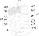
- the valve core 20 includes a shaft sleeve 271, two circular end plates 272, a plurality of axial partition plates 273, and a plurality of fan-shaped partition plates 274, the two circular end plates 272 are arranged in parallel and are both fixedly connected with the shaft sleeve 271, and the two circular end plates 272 and the shaft sleeve 271 are both coaxially arranged, wherein the plurality of axial partition plates 273 and the plurality of fan-shaped partition plates 274 are distributed in a space between the two circular end plates 272 to divide the space between the two circular end plates 272 into the first cavity 21, the second cavity 22, the third cavity 23, and the fourth cavity 24, and the single-motor actuator 30 is in driving connection with the shaft sleeve 271.
- the shaft sleeve 271 and the circular end plates 272 at two ends form a main body of the valve core 20, and then, an internal space of the main body of the valve core 20 is divided into the first cavity 21, the second cavity 22, the third cavity 23, and the fourth cavity 24 by the plurality of axial partition plates 273 and the plurality of fan-shaped partition plates 274 in the axial direction and the radial direction to form the valve core 20.
- At least one circular end plate 272 is provided with ribs to increase the structural strength of the valve core 20.
- each axial partition plate 273 and each fan-shaped partition plate 274 are both connected with the shaft sleeve 271, and the each fan-shaped partition plate 274 is connected with at least two axial partition plates 273;
- the third-second main cavity 232 includes a first sub-cavity C2 and a second sub-cavity C3 which are communicated with each other
- the fourth-second main cavity 242 includes a third sub-cavity C6 and a fourth sub-cavity C7 which are communicated with each other
- the valve core 20 further includes a first arc-shaped plate 281 and a second arc-shaped plate 282; in the circumferential direction of the valve core 20, the first arc-shaped plate 281, the first sub-cavity C2, the second sub-cavity C3, the second arc-shaped plate 282, the third sub-cavity C6, and the fourth sub-cavity C7 are sequentially arranged; in the first working condition, the first sub-cavity C2 is communicated with the third
- each axial partition plate 273 and the each fan-shaped partition plate 274 are both connected with the shaft sleeve 271, thereby facilitating the mounting and positioning of the axial partition plate 273 and the fan-shaped partition plate 274; and the each fan-shaped partition plate 274 is connected with at least two axial partition plates 273 to ensure the limiting and supporting of the fan-shaped partition plate 274, thereby ensuring the stability and reliability of the structure.
- a plurality of wave ribs extending along a circumferential direction are arranged on both the first arc-shaped plate 281 and the second arc-shaped plate 282, thereby improving the structural strength and sealing effect of the valve core 20; and the wave ribs are arranged along the circumferential direction, so that the rotary resistance of the valve core 20 is reduced.
- a bottom wall of the valve cavity 12 is provided with an arc-shaped groove 13, the arc-shaped groove 13 is arranged around an axis of the valve core 20, the five-way valve further includes a limiting block 40, the limiting block 40 is located on a side of the valve core 20 facing the bottom wall of the valve cavity 12, and the limiting block 40 is located in the arc-shaped groove 13.
- the limiting block 40 and the valve core 20 are of an integrated structure and can be formed by injection molding, so that the cost can be reduced.
- the arc-shaped groove 13 has a first arc-shaped wall, a second arc-shaped wall, a first end wall, and a second end wall
- the limiting block 40 has a fan-shaped structure
- the limiting block 40 has a third arc-shaped wall, a fourth arc-shaped wall, a third end wall, and a fourth end wall, wherein the first arc-shaped wall is matched with the third arc-shaped wall, the second arc-shaped wall is matched with the fourth arc-shaped wall, the first end wall is in stop fit with the third end wall, and the second end wall is in stop fit with the fourth end wall.
- the limiting of rotation of the valve core 20 can be achieved by rotation of the limiting block 40 in the arc-shaped groove 13, thereby preventing the situation that the rotation angle of the valve core 20 is too large or the valve core 20 cannot be accurately reset during resetting.
- valve core 20 is provided with a matching hole
- the bottom wall of the valve cavity 12 is provided with a support shaft
- the support shaft penetrates into the matching hole.
- the support shaft and the valve body 14 are of an integrated structure.
- the valve core 20 has a first setting position and a second setting position; in a case that the valve core 20 is located in the first setting position, the five-way valve is in the first working condition, and the first end wall is separated from the third end wall; in a case that the valve core 20 is located in the second setting position, the five-way valve is in the sixth working condition, and the second end wall is separated from the fourth end wall; and in a case that the five-way valve is switched from the first working condition to the sixth working condition along a rotation direction, the rotation angle of the valve core 20 is N, and the range of the rotation angle of the limiting block 40 in the arc-shaped groove 13 is greater than N.
- This arrangement allows the range of the rotation angle of the limiting block 40 in the arc-shaped groove 13 to be greater than N, the rotation of the valve core 20 is limited by the limiting block 40 and the arc-shaped groove 13, and simultaneously, a maximum rotation range of the valve core 20 is not affected. That is, the rotation angle of the limiting block 40 in the arc-shaped groove 13 is greater than N, and the margin is located at two ends of the rotation angle N, thereby ensuring the reliability of rotation of the valve core 20 of the five-way valve.
- the valve core 20 has a first setting position; in a case that the valve core 20 is located in the first setting position, the five-way valve is in the first working condition, and the valve core 20 has a reserved rotation angle M; in a case that the valve core 20 rotates in a range of the rotation angle M along the rotation direction from the first setting position, the five-way valve is maintained in the first working condition; and in a case that the valve core 20 rotates in a range greater than the rotation angle M along the rotation direction from the first setting position, the five-way valve is switched to other working conditions. As shown in Fig.
- this arrangement can prevent the situation that when the valve core 20 is located in the first setting position, the valve core 20 rotates or has a mounting error so that a small part of the third outlet 115 is blocked by the first arc-shaped plate 281, and a small part of the fourth outlet 116 is opened by the second arc-shaped plate 282. Furthermore, this arrangement provides a sufficient rotation angle and rotation time required for switching the five-way valve from the first working condition to the second working condition, so that the five-way valve remains in the first working condition when the valve core 20 is in the reserved rotation angle M, a problem that the valve core 20 is affected and an inadequate rotation due to the sudden switching of the working condition is prevented.
- the main body portion 10 includes a valve body 14 and a sealing gasket 15, the valve body 14 has the valve cavity 12, the sealing gasket 15 is arranged in the valve cavity 12, and the first inlet 113, the second inlet 114, the first outlet 112, the second outlet 111, the third outlet 115, and the fourth outlet 116 are all arranged in the sealing gasket 15, wherein the first outlet 112, the first inlet 113, and the third outlet 115 are arranged along the axial direction of the valve core 20, the second outlet 111, the second inlet 114, and the fourth outlet 116 are arranged along the axial direction of the valve core 20, the first outlet 112 and the second outlet 111 are arranged along the circumferential direction of the valve core 20, the first inlet 113 and the second inlet 114 are arranged along the circumferential direction of the valve core 20, and the third outlet 115 and the fourth outlet 116 are arranged along the circumferential direction of the valve core 20.
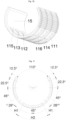
- an included angle between two ends of the sealing gasket 15 is 110°.
- an included angle between an end of the first arc-shaped plate 281 close to the third outlet 115 and a closer edge of the third outlet 115 is 8.5°
- an included angle between an end of the second arc-shaped plate 282 close to the fourth outlet 116 and a closer edge of the fourth outlet 116 is 8.5°.
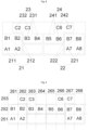
- the relationships between a plurality of main cavities and a plurality of cavities of the valve core 20 are shown in Fig. 8 .
- the first-first main cavity 211 includes a sub-cavity A1 and a sub-cavity A2 which are communicated with each other
- the first-second main cavity 212 includes a sub-cavity B1 and a sub-cavity B2 which are communicated with each other
- the third-first main cavity 231 includes a sub-cavity B3 and a sub-cavity B4 which are communicated with each other
- the fourth-first main cavity 241 includes a sub-cavity B5 and a sub-cavity B6 which are communicated with each other
- the second-first main cavity 221 includes a sub-cavity A7 and a sub-cavity A8 which are communicated with each other
- the second-second main cavity 222 includes a sub-cavity B7 and a sub-cavity B8 which are communicated with each other.
- the valve core 20 is located in the first setting position, and the rotation angle of the valve core 20 is 0°.
- the five-way valve is in the first working condition.
- the third-second main cavity 232 is communicated with the third outlet 115, the fourth outlet 116 is blocked by the second arc-shaped plate 282, the first-second main cavity 212 is communicated with the first inlet 113, the third-first main cavity 231 is communicated with the second inlet 114, the first-first main cavity 211 is communicated with the first outlet 112, the second outlet 111 is communicated with a closed cavity shown in Fig.
- the second outlet 111 has no communication relationship
- the third-second main cavity 232 is communicated with the third-first main cavity 231
- the first-second main cavity 212 is communicated with the first-first main cavity 211. Therefore, at this time, the second inlet 114 is communicated with the third outlet 115, and the first outlet 112 is communicated with the first inlet 113.
- valve core 20 When the valve core 20 anticlockwise rotates 22.5° relative to the first setting position, that is, the valve core 20 rotates a reserved rotation angle M+H1/2, at this time, the five-way valve is in the second working condition, the first arc-shaped plate 281 blocks half of the third outlet 115, the second arc-shaped plate 282 on the other side also rotates this angle, half of the fourth outlet 116 is communicated with the third-second main cavity 232, and other communication relationships are not affected.
- the second inlet 114 is respectively communicated with the third outlet 115 and the fourth outlet 116, the proportion of the fluid entering the second inlet 114 is 100%, and the proportion of the fluids flowing out from the third outlet 115 and the fourth outlet 116 is 50% respectively.
- the proportion of the fluids flowing out from the third outlet 115 and the fourth outlet 116 can be adjusted by rotating the rotation angle of the valve core 20.
- the flow rate adjusting range is the range of the rotation angle of the valve core 20, which is 8.5° to 36.5°.
- the anticlockwise rotation angle of the valve core 20 is 8.5° to 22.5°
- the proportion of the fluid flowing out from the third outlet 115 is greater than the proportion of the fluid flowing out from the fourth outlet 116.
- the anticlockwise rotation angle of the valve core 20 is 22.5°
- the fluid flowing out from the third outlet 115 is equal to the fluid flowing out from the fourth outlet 116.
- the proportion of the fluid flowing out from the third outlet 115 is less than the proportion of the fluid flowing out from the fourth outlet 116.
- the third outlet 115 is completely blocked by the first arc-shaped plate 281, and the second arc-shaped plate 282 completely avoids the fourth outlet 116; and at this time, the second inlet 114 is communicated with the fourth outlet 116, and other communication relationships remain unchanged.
- the five-way valve is in the third working condition, which is the same as the above situation when the valve core 20 anticlockwise rotates 36.5°, the third outlet 115 is completely blocked by the first arc-shaped plate 281, the second arc-shaped plate 282 completely avoids the fourth outlet 116, and other communication relationships remain unchanged; and at this time, the second inlet 114 is communicated with the fourth outlet 116, and the first outlet 112 is communicated with the first inlet 113.
- the five-way valve is in the fourth working condition.
- the fourth-second main cavity 242 is communicated with the third outlet 115, the fourth outlet 116 is blocked by the first arc-shaped plate 281
- the fourth-first main cavity 241 is communicated with the first inlet 113
- the second-second main cavity 222 is communicated with the second inlet 114
- the second-first main cavity 221 is communicated with the second outlet 111
- the first outlet 112 is communicated with the closed cavity shown in Fig. 8 and is not communicated with other cavities so that the first outlet 112 has no communication relationship. Therefore, at this time, the first inlet 113 is communicated with the third outlet 115, and the second outlet 111 is communicated with the second inlet 114.
- the five-way valve is in the fifth working condition.
- the second arc-shaped plate 282 blocks half of the third outlet 115
- the first arc-shaped plate 281 on the other side communicates half of the fourth outlet 116 with the fourth-second main cavity 242, and other communication relationships are not affected.
- the first inlet 113 is respectively communicated with the third outlet 115 and the fourth outlet 116
- the proportion of the fluid entering the first inlet 113 is 100%
- the proportion of the fluids flowing out from the third outlet 115 and the fourth outlet 116 is 50% respectively.
- the proportion of the fluids flowing out from the third outlet 115 and the fourth outlet 116 can be adjusted by rotating the rotation angle of the valve core 20.
- the flow rate adjusting range is the range of the rotation angle of the valve core 20, which is 188.5° to 216.5°.
- the proportion of the fluid flowing out from the third outlet 115 is less than the proportion of the fluid flowing out from the fourth outlet 116.
- the proportion of the fluid flowing out from the third outlet 115 is equal to the proportion of the fluid flowing out from the fourth outlet 116.
- the proportion of the fluid flowing out from the third outlet 115 is greater than the proportion of the fluid flowing out from the fourth outlet 116.
- the second arc-shaped plate 282 completely blocks the third outlet 115, and the first arc-shaped plate 281 completely avoids the fourth outlet 116; and at this time, the first inlet 113 is communicated with the fourth outlet 116, and the second outlet 111 is communicated with the second inlet 114.
- the five-way valve is in the sixth working condition, which is the same as the above situation when the valve core 20 anticlockwise rotates 202.5°, the third outlet 115 is completely blocked by the second arc-shaped plate 282, the first arc-shaped plate 281 completely avoids the fourth outlet 116, and other communication relationships remain unchanged; and at this time, the first inlet 113 is communicated with the fourth outlet 116, and the second outlet 111 is communicated with the second inlet 114.
- the first end wall of the limiting block 40 when the five-way valve is in the first working condition, the first end wall of the limiting block 40 is separated from the third end wall of the arc-shaped groove 13, a complementary angle is formed between the second end wall of the limiting block 40 and the fourth end wall of the arc-shaped groove 13, the complementary angle is 5°, and the rotation angle of the limiting block 40 in the arc-shaped groove 13 is 230°.
- the purpose of setting the complementary angle is to facilitate the positioning of the valve core 20 at an initial position.
- the second end wall of the limiting block 40 on the valve core 20 can be attached to the fourth end wall of the arc-shaped groove 13, and then, the valve core 20 is integrally rotated by 5° to ensure the accuracy of the position of the valve core 20 in the first working condition.
- the rotation angle of the valve core 20 required for switching the five-way valve from the first working condition to the sixth working condition is 225°.
- the complementary angle which is 5° may not be set.
- the valve core 20 When the valve core 20 is located in the first setting position, that is, when the rotation angle of the valve core 20 is 0°, the second end wall of the limiting block 40 abuts against the fourth end wall of the arc-shaped groove 13.
- the five-way valve also has multiple other communication working conditions which all play a four-way role and have no proportion adjusting relationship, so the working conditions are not listed one by one here.
- the sealing gasket 15 has an arc-shaped structure, an outer side of the sealing gasket 15 is attached to an inner wall of the valve cavity 12, an inner side of the sealing gasket 15 is attached to an outer circumferential surface of the valve core 20, the main body portion 10 further includes two arc-shaped baffle plates 16 arranged on the inner wall of the valve cavity 12, and the two arc-shaped baffle plates 16 respectively abut against two ends of the sealing gasket 15 in the circumferential direction; and on a side of the sealing gasket 15 facing the inner wall of the valve cavity 12, the sealing gasket 15 is distributed with a plurality of sealing ribs in the axial direction and the circumferential direction.
- the sealing gasket 15 is limited by the two arc-shaped baffle plates 16 to prevent the rotation of the sealing gasket 15 in the valve cavity 12, and the sealing gasket 15 is distributed with the plurality of sealing ribs in the axial direction and the circumferential direction, which can provide elastic margin supplementation for sealing, thereby improving the sealing reliability of the sealing gasket 15.
- a spacing between the sealing ribs extending along the axial direction of the sealing gasket 15 is less than a spacing between the sealing ribs extending along the circumferential direction of the sealing gasket 15, thereby improving the sealing reliability.
- the valve body 14 includes a base 141, a cylinder 142, and a plurality of reinforcing ribs 143, the cylinder 142 is connected with the base 141, each reinforcing rib 143 is connected with both the base 141 and an outer wall of the cylinder 142, the cylinder 142 has the valve cavity 12, the base 141 has six flow channels, and the six flow channels are respectively communicated with the first inlet 113, the second inlet 114, the first outlet 112, the second outlet 111, the third outlet 115, and the fourth outlet 116.
- the six flow channels are respectively communicated with the six inlets and outlets, so that external connecting pipes are respectively communicated with the six flow channels to achieve the communication between the exterior and the five-way valve.
- the plurality of reinforcing ribs 143 an overall structural strength of the valve body 14 is improved.
- the sealing gasket 15 is limited by the two arc-shaped baffle plates 16 arranged on the inner wall of the valve cavity 12, thereby ensuring the communication between the flow channels and the inlets and outlets, and ensuring the reliability of the five-way valve.
- a plurality of metal sleeves 144 are arranged in the base 141 to bear the downward locking force of bolts during a mounting process to prevent the downward locking force from concentrating on the valve body 14 and causing excessive force on the base 141 or cylinder 142 of the valve body 14, resulting in cracking.
- the main body portion 10 further includes a flat washer 19, the flat washer is in sealed connection with the base 141, and thus, external connecting pipes connected with flow channel openings at the positions of six flow channel openings are sealed.
- the main body portion 10 further includes a valve cover 17 and a sealing ring 18, the valve cover 17 is in sealed connection with the valve body 14, the valve cover 17 blocks an opening of the valve cavity 12, the sealing ring 18 is arranged in a groove of the valve cover 17, the five-way valve further includes a rotating shaft 50, a portion of the rotating shaft 50 is fixed in the valve core 20, the rotating shaft 50 passes through the sealing ring 18, and an output shaft of the single-motor actuator 30 is in driving connection with the rotating shaft 50.
- the sealing between the valve body 14 and the valve cover 17 is achieved by the sealing ring 18 to prevent the fluid in the valve body 14 from flowing out from the valve cover 17, thereby improving the sealing performance of the five-way valve.
- the rotating shaft 50 penetrates into the shaft sleeve 271, the rotating shaft 50 is made of a metal material, and the valve core 20 is made of plastic.
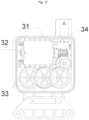
- the single-motor actuator 30 includes a housing 31 and a motor 32, a gear assembly 33, and a control plate 34 which are arranged in the housing 31, the motor 32 is in driving connection with an input shaft of the gear assembly 33, an output shaft of the gear assembly 33 is in driving connection with the valve core 20, and the housing 31 is fixedly connected with the main body portion 10.
- a control device is combined with a driving device to form the single-motor actuator 30, thereby reducing the processing and manufacturing cost of the five-way valve.
- the single-motor actuator 30 drives the valve core 20 to rotate mainly through the gear assembly 33, the structure is simple, and the transmission is reliable.
Landscapes
- Engineering & Computer Science (AREA)
- General Engineering & Computer Science (AREA)
- Mechanical Engineering (AREA)
- Multiple-Way Valves (AREA)
Abstract
Description
- The present disclosure relates to the technical field of five-way valves, specifically to a five-way valve.
- Currently, for multi-way valves in a prior art, a plurality of motors and valve cores are required to achieve the switching between multiple working conditions. Taking a five-way valve as an example, the five-way valve in the prior art usually uses two valve cores and two motors, and the two motors respectively drive the two valve cores to rotate. The switching between multiple working conditions of the five-way valve and the flow rate adjustment can be achieved by rotation of the valve core.
- The five-way valve in the prior art requires two valve cores and two motors to achieve working condition switching and flow rate adjusting functions, there are more structures, the production and manufacturing difficulty is higher, the mounting accuracy is difficult to ensure during a mounting process, and the cost is high.
- Some embodiments of the present disclosure provide a five-way valve to solve the problem of high manufacturing cost of five-way valves in the prior art.
- In order to solve the above problem, some embodiments of the present disclosure provide a five-way valve, including: a main body portion, the main body portion having a valve cavity, a first inlet, a second inlet, a first outlet, a second outlet, a third outlet, and a fourth outlet; a valve core rotatably arranged in the valve cavity, the valve core having a first cavity, a second cavity, a third cavity, and a fourth cavity which are separated; and a single-motor actuator, the single-motor actuator being in driving connection with the valve core, wherein the five-way valve can be switched to any one of the following working conditions by means of rotation of the valve core: a first working condition: the first inlet is communicated with the first outlet through the first cavity, the second inlet is communicated with the third outlet through the third cavity, and the second outlet and the fourth outlet are disconnected; a second working condition: the first inlet is communicated with the first outlet through the first cavity, the second inlet is communicated with both the third outlet and the fourth outlet through the third cavity, and the second outlet is disconnected; a third working condition: the first inlet is communicated with the first outlet through the first cavity, the second inlet is communicated with the fourth outlet through the third cavity, and both the third outlet and the second outlet are disconnected; a fourth working condition: the second inlet is communicated with the second outlet through the second cavity, the first inlet is communicated with the third outlet through the fourth cavity, and both the first outlet and the fourth outlet are disconnected; a fifth working condition: the second inlet is communicated with the second outlet through the second cavity, the first inlet is communicated with both the third outlet and the fourth outlet through the fourth cavity, and the first outlet is disconnected; and a sixth working condition: the second inlet is communicated with the second outlet through the second cavity, the first inlet is communicated with the fourth outlet through the fourth cavity, and the first outlet and the third outlet are disconnected.
- Further, in the second working condition, the single-motor actuator is configured to drive the valve core to rotate and maintain at multiple different positions to adjust a proportion of fluids output from the third outlet and the fourth outlet; and in the fifth working condition, the single-motor actuator is configured to drive the valve core to rotate and maintain at multiple different positions to adjust a proportion of fluids output from the third outlet and the fourth outlet.
- Further, the valve core includes a first axial region, a second axial region, and a third axial region which are sequentially arranged in an axial direction, and openings of the first cavity, the second cavity, the third cavity, and the fourth cavity all face an inner wall of the valve cavity; and the first cavity includes a first-first main cavity and a first-second main cavity which are communicated with each other, the third cavity includes a third-first main cavity and a third-second main cavity which are communicated with each other, the second cavity includes a second-first main cavity and a second-second main cavity which are communicated with each other, and the fourth cavity includes a fourth-first main cavity and a fourth-second main cavity which are communicated with each other, wherein the first-first main cavity and the second-first main cavity are both located in the first axial region, the first-second main cavity, the third-first main cavity, the fourth-first main cavity, and the second-second main cavity are all located in the second axial region, and the third-second main cavity and the fourth-second main cavity are both arranged in the third axial region.
- Further, the valve core includes a first fan-shaped region, a second fan-shaped region, a third fan-shaped region, a fourth fan-shaped region, a fifth fan-shaped region, a sixth fan-shaped region, a seventh fan-shaped region, and an eighth fan-shaped region which are sequentially arranged in a circumferential direction, wherein the first-first main cavity is distributed in the first fan-shaped region and the second fan-shaped region, the first-second main cavity is distributed in the first fan-shaped region and the second fan-shaped region, the third-first main cavity is distributed in the third fan-shaped region and the fourth fan-shaped region, the third-second main cavity is distributed in the second fan-shaped region and the third fan-shaped region, the second-first main cavity is distributed in the seventh fan-shaped region and the eighth fan-shaped region, the second-second main cavity is distributed in the seventh fan-shaped region and the eighth fan-shaped region, the fourth-first main cavity is distributed in the fifth fan-shaped region and the sixth fan-shaped region, and the fourth-second main cavity is distributed in the sixth fan-shaped region and the seventh fan-shaped region.
- Further, in the axial direction of the valve core, lengths of the first axial region, the second axial region, and the third axial region are equal; and in the circumferential direction of the valve core, radians of the first fan-shaped region, the second fan-shaped region, the third fan-shaped region, the fourth fan-shaped region, the fifth fan-shaped region, the sixth fan-shaped region, the seventh fan-shaped region, and the eighth fan-shaped region are equal.
- Further, in a circumferential direction of the valve core, opening angles of the third outlet and the fourth outlet are both H1, a spacing angle between the third outlet and the fourth outlet is H2, and opening angles of the third-second main cavity and the fourth-second main cavity are both H3, wherein H1<H2<H3.
- Further, the valve core includes a shaft sleeve, two circular end plates, a plurality of axial partition plates, and a plurality of fan-shaped partition plates, the two circular end plates are arranged in parallel and are both fixedly connected with the shaft sleeve, and the two circular end plates and the shaft sleeve are both coaxially arranged, wherein the plurality of axial partition plates and the plurality of fan-shaped partition plates are distributed in a space between the two circular end plates to divide the space between the two circular end plates into the first cavity, the second cavity, the third cavity, and the fourth cavity, and the single-motor actuator is in driving connection with the shaft sleeve.
- Further, each of the plurality of axial partition plates and each of the plurality of fan-shaped partition plates are both connected with the shaft sleeve, and the each of the plurality of fan-shaped partition plates is connected with at least two axial partition plates in the plurality of axial partition plates; the third-second main cavity includes a first sub-cavity and a second sub-cavity which are communicated with each other, the fourth-second main cavity includes a third sub-cavity and a fourth sub-cavity which are communicated with each other, and the valve core further includes a first arc-shaped plate and a second arc-shaped plate; in the circumferential direction of the valve core, the first arc-shaped plate, the first sub-cavity, the second sub-cavity, the second arc-shaped plate, the third sub-cavity, and the fourth sub-cavity are sequentially arranged; in the first working condition, the first sub-cavity is connected to the third outlet, and the second arc-shaped plate blocks the fourth outlet; in the third working condition, the second sub-cavity is connected to the fourth outlet, and the first arc-shaped plate blocks the third outlet; in the fourth working condition, the third sub-cavity is connected to the third outlet, and the first arc-shaped plate blocks the fourth outlet; and in the sixth working condition, the fourth sub-cavity is connected to the fourth outlet, and the second arc-shaped plate blocks the third outlet.
- Further, a bottom wall of the valve cavity is provided with an arc-shaped groove, the arc-shaped groove is arranged around an axis of the valve core, the five-way valve further includes a limiting block, the limiting block is located on a side of the valve core facing the bottom wall of the valve cavity, and the limiting block is located in the arc-shaped groove.
- Further, the arc-shaped groove has a first arc-shaped wall, a second arc-shaped wall, a first end wall, and a second end wall, the limiting block has a fan-shaped structure, and the limiting block has a third arc-shaped wall, a fourth arc-shaped wall, a third end wall, and a fourth end wall, wherein the first arc-shaped wall is matched with the third arc-shaped wall, the second arc-shaped wall is matched with the fourth arc-shaped wall, the first end wall is in stop fit with the third end wall, and the second end wall is in stop fit with the fourth end wall.
- Further, the valve core has a first setting position and a second setting position; in a case that the valve core is located in the first setting position, the five-way valve is in the first working condition, and the first end wall is separated from the third end wall; in a case that the valve core is located in the second setting position, the five-way valve is in the sixth working condition, and the second end wall is separated from the fourth end wall; and in a case that the five-way valve is switched from the first working condition to the sixth working condition along a rotation direction, a rotation angle of the valve core is N, and a range of a rotation angle of the limiting block in the arc-shaped groove is greater than N.
- Further, the valve core has a first setting position; in a case that the valve core is located in the first setting position, the five-way valve is in the first working condition, and the valve core has a reserved rotation angle M; in a case that the valve core rotates in a range of the rotation angle M along a rotation direction from the first setting position, the five-way valve is maintained in the first working condition; and in a case that the valve core rotates in a range greater than the rotation angle M along the rotation direction from the first setting position, the five-way valve is switched to other working conditions.
- Further, the main body portion includes a valve body and a sealing gasket, the valve body has the valve cavity, the sealing gasket is arranged in the valve cavity, and the first inlet, the second inlet, the first outlet, the second outlet, the third outlet, and the fourth outlet are all arranged in the sealing gasket, wherein the first outlet, the first inlet, and the third outlet are arranged along an axial direction of the valve core, the second outlet, the second inlet, and the fourth outlet are arranged along the axial direction of the valve core, the first outlet and the second outlet are arranged along the circumferential direction of the valve core, the first inlet and the second inlet are arranged along the circumferential direction of the valve core, and the third outlet and the fourth outlet are arranged along the circumferential direction of the valve core.
- Further, the sealing gasket has an arc-shaped structure, an outer side of the sealing gasket is attached to an inner wall of the valve cavity, an inner side of the sealing gasket is attached to an outer circumferential surface of the valve core, the main body portion further includes two arc-shaped baffle plates arranged on the inner wall of the valve cavity, and the two arc-shaped baffle plates respectively abut against two ends of the sealing gasket in a circumferential direction; and on a side of the sealing gasket facing the inner wall of the valve cavity, the sealing gasket is distributed with a plurality of sealing ribs in the axial direction and the circumferential direction.
- Further, the valve body includes a base, a cylinder, and a plurality of reinforcing ribs, the cylinder is connected with the base, each of the plurality of reinforcing ribs is connected with both the base and an outer wall of the cylinder, the cylinder has the valve cavity, the base has six flow channels, and the six flow channels are respectively communicated with the first inlet, the second inlet, the first outlet, the second outlet, the third outlet, and the fourth outlet.
- Further, the main body portion further includes a valve cover and a sealing ring, the valve cover is in sealed connection with the valve body, the valve cover blocks an opening of the valve cavity, the sealing ring is arranged in a groove of the valve cover, the five-way valve further includes a rotating shaft, a portion of the rotating shaft is fixed in the valve core, the rotating shaft passes through the sealing ring, and an output shaft of the single-motor actuator is in driving connection with the rotating shaft.
- Further, the single-motor actuator includes a housing and a motor, a gear assembly, and a control plate which are arranged in the housing, the motor is in driving connection with an input shaft of the gear assembly, an output shaft of the gear assembly is in driving connection with the valve core, and the housing is fixedly connected with the main body portion.
- The technical solution of the present disclosure provides a five-way valve, including: a main body portion, the main body portion having a valve cavity, a first inlet, a second inlet, a first outlet, a second outlet, a third outlet, and a fourth outlet; a valve core rotatably arranged in the valve cavity, the valve core having a first cavity, a second cavity, a third cavity, and a fourth cavity which are separated; and a single-motor actuator, the single-motor actuator being in driving connection with the valve core, wherein the five-way valve can be switched to any one of the following working conditions by means of rotation of the valve core: a first working condition: the first inlet is communicated with the first outlet through the first cavity, the second inlet is communicated with the third outlet through the third cavity, and the second outlet and the fourth outlet are disconnected; a second working condition: the first inlet is communicated with the first outlet through the first cavity, the second inlet is communicated with both the third outlet and the fourth outlet through the third cavity, and the second outlet is disconnected; a third working condition: the first inlet is communicated with the first outlet through the first cavity, the second inlet is communicated with the fourth outlet through the third cavity, and the third outlet and the second outlet are disconnected; a fourth working condition: the second inlet is communicated with the second outlet through the second cavity, the first inlet is communicated with the third outlet through the fourth cavity, and the first outlet and the fourth outlet are disconnected; a fifth working condition: the second inlet is communicated with the second outlet through the second cavity, the first inlet is communicated with both the third outlet and the fourth outlet through the fourth cavity, and the first outlet is disconnected; and a sixth working condition: the second inlet is communicated with the second outlet through the second cavity, the first inlet is communicated with the fourth outlet through the fourth cavity, and the first outlet and the third outlet are disconnected. By means of this solution, the switching between multiple working conditions of the five-way valve can be achieved by using one single-motor actuator to drive one valve core to rotate. Compared with the situation in the prior art that the switching between working conditions of the five-way valve can be achieved only by using two motors to respectively drive two valve cores, this solution of the present disclosure reduces a set of single-motor actuator and valve core, thereby reducing the production and manufacturing difficulty of the five-way valve, improving the mounting accuracy of the overall structure of the five-way valve, and reducing the manufacturing cost of the five-way valve.
- The accompanying drawings of the specification, constituting a part of the present disclosure, are used for providing a further understanding for the present disclosure. Exemplary embodiments of the present disclosure and descriptions thereof are used for explaining the present disclosure, but do not constitute any improper limitation on the present disclosure. In the accompanying drawings:
-
Fig. 1 shows a schematic structural view of a five-way valve provided in an embodiment of the present disclosure; -
Fig. 2 shows an exploded view of the five-way valve inFig. 1 ; -
Fig. 3 shows an exploded view of partial structures in the five-way valve inFig. 1 ; -
Fig. 4 shows a schematic structural view of a valve body of the five-way valve inFig. 1 ; -
Fig. 5 shows a bottom view of the five-way valve inFig. 1 ; -
Fig. 6 shows a schematic structural view of a valve core of the five-way valve inFig. 1 ; -
Fig. 7 shows a schematic structural view of the valve core inFig. 6 from another perspective; -
Fig. 8 shows a circumferentially expanded schematic view of the valve core inFig. 6 ; -
Fig. 9 shows a region division schematic view of the valve core inFig. 8 ; -
Fig. 10 shows a schematic structural view of a sealing gasket of the five-way valve inFig. 1 ; -
Fig. 11 shows a cross-sectional view of the sealing gasket inFig. 8 ; -
Fig. 12 shows a side view of a main body portion and the valve core of the five-way valve inFig. 1 ; -
Fig. 13 shows a cross-sectional view of a position D-D inFig. 12 ; -
Fig. 14 shows a cross-sectional view of a position E-E inFig. 12 ; -
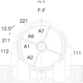
Fig. 15 shows a cross-sectional view of a position F-F inFig. 12 ; -
Fig. 16 shows a cross-sectional view of a position G-G inFig. 12 ; and -
Fig. 17 shows a schematic structural view of a single-motor actuator of the five-way valve inFig. 1 . - The above accompanying drawings have the following reference numerals:
- 10. main body portion; 111. second outlet; 112. first outlet; 113. first inlet; 114. second inlet; 115. third outlet; 116. fourth outlet; 12. valve cavity; 13. arc-shaped groove; 14. valve body; 141. base; 142. cylinder; 143. reinforcing rib; 144. metal sleeve; 15. sealing gasket; 16. arc-shaped baffle plate; 17. valve cover; 18. sealing ring; 19. flat washer;
- 20. valve core; 21. first cavity; 211. first-first main cavity; 212. first-second main cavity; 22. second cavity; 221. second-first main cavity; 222. second-second main cavity; 23. third cavity; 231. third-first main cavity; 232. third-second main cavity; 24. fourth cavity; 241. fourth-first main cavity; 242. fourth-second main cavity; 251. first axial region; 252. second axial region; 253. third axial region; 261. first fan-shaped region; 262. second fan-shaped region; 263. third fan-shaped region; 264. fourth fan-shaped region; 265. fifth fan-shaped region; 266. sixth fan-shaped region; 267. seventh fan-shaped region; 268. eighth fan-shaped region; 271. shaft sleeve; 272. circular end plate; 273. axial partition plate; 274. fan-shaped partition plate; 281. first arc-shaped plate; 282. second arc-shaped plate;
- 30. single-motor actuator; 31. housing; 32. motor; 33. gear assembly; 34. control plate;
- 40. limiting block;
- 50. rotating shaft;
- C2. first sub-cavity; C3. second sub-cavity; C6. third sub-cavity; C7. fourth sub-cavity.
- The technical solutions in the embodiments of the present disclosure are clearly and completely described below with reference to the accompanying drawings in the embodiments of the present disclosure. Apparently, the described embodiments are only some embodiments rather than all the embodiments of the present disclosure. The following description of at least one exemplary embodiment is actually only illustrative, and does not constitute any limitation on the present disclosure and the application or use of the present disclosure. All other embodiments obtained by those of ordinary skill in the art based on the embodiments in the present disclosure without creative efforts shall fall within the protection scope of the present disclosure.
- As shown in
Fig. 1 to Fig. 17 , an embodiment of the present disclosure provides a five-way valve, including: a main body portion 10, the main body portion 10 has a valve cavity 12, a first inlet 113, a second inlet 114, a first outlet 112, a second outlet 111, a third outlet 115, and a fourth outlet 116; a valve core 20 rotatably arranged in the valve cavity 12, the valve core 20 has a first cavity 21, a second cavity 22, a third cavity 23, and a fourth cavity 24 which are separated; and a single-motor actuator 30, the single-motor actuator 30 is in driving connection with the valve core 20, wherein the five-way valve can be switched to any one of the following working conditions by means of rotation of the valve core 20: a first working condition: the first inlet 113 is communicated with the first outlet 112 through the first cavity 21, the second inlet 114 is communicated with the third outlet 115 through the third cavity 23, and the second outlet 111 and the fourth outlet 116 are disconnected; a second working condition: the first inlet 113 is communicated with the first outlet 112 through the first cavity 21, the second inlet 114 is communicated with both the third outlet 115 and the fourth outlet 116 through the third cavity 23, and the second outlet 111 is disconnected; a third working condition: the first inlet 113 is communicated with the first outlet 112 through the first cavity 21, the second inlet 114 is communicated with the fourth outlet 116 through the third cavity 23, and the third outlet 115 and the second outlet 111 are disconnected; a fourth working condition: the second inlet 114 is communicated with the second outlet 111 through the second cavity 22, the first inlet 113 is communicated with the third outlet 115 through the fourth cavity 24, and the first outlet 112 and the fourth outlet 116 are disconnected; a fifth working condition: the second inlet 114 is communicated with the second outlet 111 through the second cavity 22, the first inlet 113 is communicated with both the third outlet 115 and the fourth outlet 116 through the fourth cavity 24, and the first outlet 112 is disconnected; and a sixth working condition: the second inlet 114 is communicated with the second outlet 111 through the second cavity 22, the first inlet 113 is communicated with the fourth outlet 116 through the fourth cavity 24, and the first outlet 112 and the third outlet 115 are disconnected. - In this embodiment, the switching between multiple working conditions of the five-way valve can be achieved by using one single-
motor actuator 30 to drive onevalve core 20 to rotate. Compared with the situation in a prior art that the switching between working conditions of the five-way valve can be achieved only by using two motors to respectively drive twovalve cores 20, this solution reduces a set of motor andvalve core 20, thereby reducing the production and manufacturing difficulty of the five-way valve, improving a mounting accuracy of the overall structure of the five-way valve, and reducing a manufacturing cost of the five-way valve. - Specifically, in the second working condition, the single-
motor actuator 30 is able to drive thevalve core 20 to rotate and maintain at multiple different positions to adjust the proportion of fluids output from thethird outlet 115 and thefourth outlet 116; and in the fifth working condition, the single-motor actuator 30 is able to drive thevalve core 20 to rotate and maintain at multiple different positions to adjust the proportion of fluids output from thethird outlet 115 and thefourth outlet 116. - In this embodiment, a flow rate of the outlet of the five-way valve in the second working condition and the fifth working condition is adjusted by using one single-
motor actuator 30 to drive onevalve core 20 to rotate. Compared with the situation in the prior art that the adjustment of the flow rate of the outlet of the five-way valve is achieved by using two motors to respectively drive twovalve cores 20 to rotate, this solution reduces a set of motor andvalve core 20, thereby reducing the production and manufacturing difficulty and manufacturing cost of the five-way valve. - As shown in
Fig. 8 and Fig. 9 , the valve core 20 includes a first axial region 251, a second axial region 252, and a third axial region 253 which are sequentially arranged in an axial direction, and openings of the first cavity 21, the second cavity 22, the third cavity 23, and the fourth cavity 24 all face an inner wall of the valve cavity 12; and the first cavity 21 includes a first-first main cavity 211 and a first-second main cavity 212 which are communicated with each other, the third cavity 23 includes a third-first main cavity 231 and a third-second main cavity 232 which are communicated with each other, the second cavity 22 includes a second-first main cavity 221 and a second-second main cavity 222 which are communicated with each other, and the fourth cavity 24 includes a fourth-first main cavity 241 and a fourth-second main cavity 242 which are communicated with each other, wherein the first-first main cavity 211 and the second-first main cavity 221 are both located in the first axial region 251, the first-second main cavity 212, the third-first main cavity 231, the fourth-first main cavity 241, and the second-second main cavity 222 are all located in the second axial region 252, and the third-second main cavity 232 and the fourth-second main cavity 242 are both arranged in the third axial region 253. - In this embodiment, a plurality of cavities for achieving a flow rate adjusting function and a working condition switching function of the five-way valve are arranged on the
same valve core 20, that is, thevalve core 20 is divided into three layers: the firstaxial region 251, the secondaxial region 252, and the thirdaxial region 253, and the plurality of cavities with circulation relationships, namely thefirst cavity 21, thesecond cavity 22, thethird cavity 23, and thefourth cavity 24, are limited on the firstaxial region 251, the secondaxial region 252, and the thirdaxial region 253. By this arrangement, two communication segments which are communicated with each other in each cavity can be separated in the axial direction, and the communication between different cavities and different inlets and outlets can be achieved by means of rotation of thevalve core 20, thereby achieving the purposes of working condition switching and flow rate adjustment. Compared with the situation in the prior art that the flow rate adjustment and working condition switching of the five-way valve can be achieved by means of rotation of two valve cores, this embodiment of the present disclosure combines the functions of two valve cores to form anew valve core 20, thereby reducing the production cost of the five-way valve. - As shown in
Fig. 8 and Fig. 9 , the valve core 20 includes a first fan-shaped region 261, a second fan-shaped region 262, a third fan-shaped region 263, a fourth fan-shaped region 264, a fifth fan-shaped region 265, a sixth fan-shaped region 266, a seventh fan-shaped region 267, and an eighth fan-shaped region 268 which are sequentially arranged in a circumferential direction, wherein the first-first main cavity 211 is distributed in the first fan-shaped region 261 and the second fan-shaped region 262, the first-second main cavity 212 is distributed in the first fan-shaped region 261 and the second fan-shaped region 262, the third-first main cavity 231 is distributed in the third fan-shaped region 263 and the fourth fan-shaped region 264, the third-second main cavity 232 is distributed in the second fan-shaped region 262 and the third fan-shaped region 263, the second-first main cavity 221 is distributed in the seventh fan-shaped region 267 and the eighth fan-shaped region 268, the second-second main cavity 222 is distributed in the seventh fan-shaped region 267 and the eighth fan-shaped region 268, the fourth-first main cavity 241 is distributed in the fifth fan-shaped region 265 and the sixth fan-shaped region 266, and the fourth-second main cavity 242 is distributed in the sixth fan-shaped region 266 and the seventh fan-shaped region 267. - In this embodiment, a plurality of cavities for achieving a flow rate adjusting function and a working condition switching function of the five-way valve are arranged on the
same valve core 20, that is, thevalve core 20 is divided into eight columns: the first fan-shapedregion 261, the second fan-shapedregion 262, the third fan-shapedregion 263, the fourth fan-shapedregion 264, the fifth fan-shapedregion 265, the sixth fan-shapedregion 266, the seventh fan-shapedregion 267, and the eighth fan-shapedregion 268, and the plurality of cavities with circulation relationships are limited in the plurality of fan-shaped regions. By this arrangement, two communication segments which are communicated with each other in each cavity can be separated in the radial direction, and the communication between different cavities and different inlets and outlets can be achieved by means of rotation of thevalve core 20, thereby achieving the purposes of working condition switching and flow rate adjustment. Compared with the situation in the prior art that the function of the five-way valve can be achieved by means of rotation of two valve cores, this embodiment combines the functions of two valve cores to form anew valve core 20, thereby reducing the production cost of the five-way valve. - In some embodiments, in the axial direction of the
valve core 20, the lengths of the firstaxial region 251, the secondaxial region 252, and the thirdaxial region 253 are equal; and in the circumferential direction of thevalve core 20, the radians of the first fan-shapedregion 261, the second fan-shapedregion 262, the third fan-shapedregion 263, the fourth fan-shapedregion 264, the fifth fan-shapedregion 265, the sixth fan-shapedregion 266, the seventh fan-shapedregion 267, and the eighth fan-shapedregion 268 are equal. - In an embodiment, by limiting the lengths of the first
axial region 251, the secondaxial region 252, and the thirdaxial region 253 to be equal, the communication areas between the cavity on each axial region and the inlet and outlet of themain body portion 10 are limited to be equal, thereby preventing the situation that the flow rates of the inlet and outlet of the five-way valve are different due to unequal communication areas between different axis regions and the inlet and outlet. By limiting the radians of the plurality of fan-shaped regions to be equal, the rotation angle of each fan-shaped region corresponding to thevalve core 20 is ensured to be equal, thereby ensuring the rotation reliability of thevalve core 20. - As shown in
Fig. 11 , in the circumferential direction of thevalve core 20, the opening angles of thethird outlet 115 and thefourth outlet 116 are both H1, the spacing angle between thethird outlet 115 and thefourth outlet 116 is H2, and the opening angles of the third-secondmain cavity 232 and the fourth-secondmain cavity 242 are both H3, wherein H1<H2<H3. By this arrangement, because H3>H2, it can be ensured that when thevalve core 20 rotates a certain angle, thethird outlet 115 and thefourth outlet 116 can be communicated simultaneously to ensure the performance of the five-way valve. - As shown in
Fig. 6 andFig. 7 , thevalve core 20 includes ashaft sleeve 271, twocircular end plates 272, a plurality ofaxial partition plates 273, and a plurality of fan-shapedpartition plates 274, the twocircular end plates 272 are arranged in parallel and are both fixedly connected with theshaft sleeve 271, and the twocircular end plates 272 and theshaft sleeve 271 are both coaxially arranged, wherein the plurality ofaxial partition plates 273 and the plurality of fan-shapedpartition plates 274 are distributed in a space between the twocircular end plates 272 to divide the space between the twocircular end plates 272 into thefirst cavity 21, thesecond cavity 22, thethird cavity 23, and thefourth cavity 24, and the single-motor actuator 30 is in driving connection with theshaft sleeve 271. - In an embodiment, the
shaft sleeve 271 and thecircular end plates 272 at two ends form a main body of thevalve core 20, and then, an internal space of the main body of thevalve core 20 is divided into thefirst cavity 21, thesecond cavity 22, thethird cavity 23, and thefourth cavity 24 by the plurality ofaxial partition plates 273 and the plurality of fan-shapedpartition plates 274 in the axial direction and the radial direction to form thevalve core 20. By this arrangement, it can be ensured that main cavities which are communicated with each other in each cavity can be separated in both the axial direction and radial direction of thevalve core 20, and thefirst cavity 21, thesecond cavity 22, thethird cavity 23, and thefourth cavity 24 can also be separated in the axial direction and radial direction of thevalve core 20, thereby ensuring the performance of thevalve core 20. - In some embodiments, at least one
circular end plate 272 is provided with ribs to increase the structural strength of thevalve core 20. - In some embodiments, each axial partition plate 273 and each fan-shaped partition plate 274 are both connected with the shaft sleeve 271, and the each fan-shaped partition plate 274 is connected with at least two axial partition plates 273; the third-second main cavity 232 includes a first sub-cavity C2 and a second sub-cavity C3 which are communicated with each other, the fourth-second main cavity 242 includes a third sub-cavity C6 and a fourth sub-cavity C7 which are communicated with each other, and the valve core 20 further includes a first arc-shaped plate 281 and a second arc-shaped plate 282; in the circumferential direction of the valve core 20, the first arc-shaped plate 281, the first sub-cavity C2, the second sub-cavity C3, the second arc-shaped plate 282, the third sub-cavity C6, and the fourth sub-cavity C7 are sequentially arranged; in the first working condition, the first sub-cavity C2 is communicated with the third outlet 115, and the second arc-shaped plate 282 blocks the fourth outlet 116; in the third working condition, the second sub-cavity C3 is communicated with the fourth outlet 116, and the first arc-shaped plate 281 blocks the third outlet 115; in the fourth working condition, the third sub-cavity C6 is communicated with the third outlet 115, and the first arc-shaped plate 281 blocks the fourth outlet 116; and in the sixth working condition, the fourth sub-cavity C7 is communicated with the fourth outlet 116, and the second arc-shaped plate 282 blocks the third outlet 115. In this embodiment, the each
axial partition plate 273 and the each fan-shapedpartition plate 274 are both connected with theshaft sleeve 271, thereby facilitating the mounting and positioning of theaxial partition plate 273 and the fan-shapedpartition plate 274; and the each fan-shapedpartition plate 274 is connected with at least twoaxial partition plates 273 to ensure the limiting and supporting of the fan-shapedpartition plate 274, thereby ensuring the stability and reliability of the structure. - In some embodiments, a plurality of wave ribs extending along a circumferential direction are arranged on both the first arc-shaped
plate 281 and the second arc-shapedplate 282, thereby improving the structural strength and sealing effect of thevalve core 20; and the wave ribs are arranged along the circumferential direction, so that the rotary resistance of thevalve core 20 is reduced. - As shown in
Fig. 4 to Fig. 7 , a bottom wall of the valve cavity 12 is provided with an arc-shapedgroove 13, the arc-shapedgroove 13 is arranged around an axis of thevalve core 20, the five-way valve further includes a limitingblock 40, the limitingblock 40 is located on a side of thevalve core 20 facing the bottom wall of the valve cavity 12, and the limitingblock 40 is located in the arc-shapedgroove 13. - In some embodiments, the limiting
block 40 and thevalve core 20 are of an integrated structure and can be formed by injection molding, so that the cost can be reduced. - As shown in
Fig. 16 , the arc-shapedgroove 13 has a first arc-shaped wall, a second arc-shaped wall, a first end wall, and a second end wall, the limitingblock 40 has a fan-shaped structure, and the limitingblock 40 has a third arc-shaped wall, a fourth arc-shaped wall, a third end wall, and a fourth end wall, wherein the first arc-shaped wall is matched with the third arc-shaped wall, the second arc-shaped wall is matched with the fourth arc-shaped wall, the first end wall is in stop fit with the third end wall, and the second end wall is in stop fit with the fourth end wall. By this arrangement, the limiting of rotation of thevalve core 20 can be achieved by rotation of the limitingblock 40 in the arc-shapedgroove 13, thereby preventing the situation that the rotation angle of thevalve core 20 is too large or thevalve core 20 cannot be accurately reset during resetting. - In some embodiments, the
valve core 20 is provided with a matching hole, the bottom wall of the valve cavity 12 is provided with a support shaft, and the support shaft penetrates into the matching hole. The support shaft and thevalve body 14 are of an integrated structure. - In some embodiments, the
valve core 20 has a first setting position and a second setting position; in a case that thevalve core 20 is located in the first setting position, the five-way valve is in the first working condition, and the first end wall is separated from the third end wall; in a case that thevalve core 20 is located in the second setting position, the five-way valve is in the sixth working condition, and the second end wall is separated from the fourth end wall; and in a case that the five-way valve is switched from the first working condition to the sixth working condition along a rotation direction, the rotation angle of thevalve core 20 is N, and the range of the rotation angle of the limitingblock 40 in the arc-shapedgroove 13 is greater than N. This arrangement allows the range of the rotation angle of the limitingblock 40 in the arc-shapedgroove 13 to be greater than N, the rotation of thevalve core 20 is limited by the limitingblock 40 and the arc-shapedgroove 13, and simultaneously, a maximum rotation range of thevalve core 20 is not affected. That is, the rotation angle of the limitingblock 40 in the arc-shapedgroove 13 is greater than N, and the margin is located at two ends of the rotation angle N, thereby ensuring the reliability of rotation of thevalve core 20 of the five-way valve. - In some embodiments, the
valve core 20 has a first setting position; in a case that thevalve core 20 is located in the first setting position, the five-way valve is in the first working condition, and thevalve core 20 has a reserved rotation angle M; in a case that thevalve core 20 rotates in a range of the rotation angle M along the rotation direction from the first setting position, the five-way valve is maintained in the first working condition; and in a case that thevalve core 20 rotates in a range greater than the rotation angle M along the rotation direction from the first setting position, the five-way valve is switched to other working conditions. As shown inFig. 13 , this arrangement can prevent the situation that when thevalve core 20 is located in the first setting position, thevalve core 20 rotates or has a mounting error so that a small part of thethird outlet 115 is blocked by the first arc-shapedplate 281, and a small part of thefourth outlet 116 is opened by the second arc-shapedplate 282. Furthermore, this arrangement provides a sufficient rotation angle and rotation time required for switching the five-way valve from the first working condition to the second working condition, so that the five-way valve remains in the first working condition when thevalve core 20 is in the reserved rotation angle M, a problem that thevalve core 20 is affected and an inadequate rotation due to the sudden switching of the working condition is prevented. - In some embodiments, the
main body portion 10 includes avalve body 14 and a sealinggasket 15, thevalve body 14 has the valve cavity 12, the sealinggasket 15 is arranged in the valve cavity 12, and thefirst inlet 113, thesecond inlet 114, thefirst outlet 112, thesecond outlet 111, thethird outlet 115, and thefourth outlet 116 are all arranged in the sealinggasket 15, wherein thefirst outlet 112, thefirst inlet 113, and thethird outlet 115 are arranged along the axial direction of thevalve core 20, thesecond outlet 111, thesecond inlet 114, and thefourth outlet 116 are arranged along the axial direction of thevalve core 20, thefirst outlet 112 and thesecond outlet 111 are arranged along the circumferential direction of thevalve core 20, thefirst inlet 113 and thesecond inlet 114 are arranged along the circumferential direction of thevalve core 20, and thethird outlet 115 and thefourth outlet 116 are arranged along the circumferential direction of thevalve core 20. - Specifically, as shown in
Fig. 11 , an included angle between two ends of the sealinggasket 15 is 110°. - In an embodiment, as shown in
Fig. 10 to Fig. 16 , reserved rotation angles M=8.5°, N=225°, H1=28°, H2=62°, and H3=90°. In some embodiments, as shown inFig. 13 , an included angle between an end of the first arc-shapedplate 281 close to thethird outlet 115 and a closer edge of thethird outlet 115 is 8.5°, and an included angle between an end of the second arc-shapedplate 282 close to thefourth outlet 116 and a closer edge of thefourth outlet 116 is 8.5°. Specifically, the relationships between a plurality of main cavities and a plurality of cavities of thevalve core 20 are shown inFig. 8 . - In some embodiments, as shown in
Fig. 8 , the first-firstmain cavity 211 includes a sub-cavity A1 and a sub-cavity A2 which are communicated with each other, the first-secondmain cavity 212 includes a sub-cavity B1 and a sub-cavity B2 which are communicated with each other, the third-firstmain cavity 231 includes a sub-cavity B3 and a sub-cavity B4 which are communicated with each other, the fourth-firstmain cavity 241 includes a sub-cavity B5 and a sub-cavity B6 which are communicated with each other, the second-firstmain cavity 221 includes a sub-cavity A7 and a sub-cavity A8 which are communicated with each other, and the second-secondmain cavity 222 includes a sub-cavity B7 and a sub-cavity B8 which are communicated with each other. - As shown in
Fig. 11 to Fig. 16 , thevalve core 20 is located in the first setting position, and the rotation angle of thevalve core 20 is 0°. At this time, the five-way valve is in the first working condition. At this time, the third-secondmain cavity 232 is communicated with thethird outlet 115, thefourth outlet 116 is blocked by the second arc-shapedplate 282, the first-secondmain cavity 212 is communicated with thefirst inlet 113, the third-firstmain cavity 231 is communicated with thesecond inlet 114, the first-firstmain cavity 211 is communicated with thefirst outlet 112, thesecond outlet 111 is communicated with a closed cavity shown inFig. 8 and is not communicated with other cavities, so that thesecond outlet 111 has no communication relationship, the third-secondmain cavity 232 is communicated with the third-firstmain cavity 231, and the first-secondmain cavity 212 is communicated with the first-firstmain cavity 211. Therefore, at this time, thesecond inlet 114 is communicated with thethird outlet 115, and thefirst outlet 112 is communicated with thefirst inlet 113. - When the
valve core 20 anticlockwise rotates 22.5° relative to the first setting position, that is, thevalve core 20 rotates a reserved rotation angle M+H1/2, at this time, the five-way valve is in the second working condition, the first arc-shapedplate 281 blocks half of thethird outlet 115, the second arc-shapedplate 282 on the other side also rotates this angle, half of thefourth outlet 116 is communicated with the third-secondmain cavity 232, and other communication relationships are not affected. At this time, thesecond inlet 114 is respectively communicated with thethird outlet 115 and thefourth outlet 116, the proportion of the fluid entering thesecond inlet 114 is 100%, and the proportion of the fluids flowing out from thethird outlet 115 and thefourth outlet 116 is 50% respectively. In this case, the proportion of the fluids flowing out from thethird outlet 115 and thefourth outlet 116 can be adjusted by rotating the rotation angle of thevalve core 20. Specifically, the flow rate adjusting range is the range of the rotation angle of thevalve core 20, which is 8.5° to 36.5°. When the anticlockwise rotation angle of thevalve core 20 is 8.5° to 22.5°, the proportion of the fluid flowing out from thethird outlet 115 is greater than the proportion of the fluid flowing out from thefourth outlet 116. When the anticlockwise rotation angle of thevalve core 20 is 22.5°, the fluid flowing out from thethird outlet 115 is equal to the fluid flowing out from thefourth outlet 116. When the anticlockwise rotation angle of thevalve core 20 is 22.5° to 36.5°, the proportion of the fluid flowing out from thethird outlet 115 is less than the proportion of the fluid flowing out from thefourth outlet 116. When the anticlockwise rotation angle of thevalve core 20 is 36.5°, thethird outlet 115 is completely blocked by the first arc-shapedplate 281, and the second arc-shapedplate 282 completely avoids thefourth outlet 116; and at this time, thesecond inlet 114 is communicated with thefourth outlet 116, and other communication relationships remain unchanged. - When the
valve core 20 anticlockwise rotates 45°, the five-way valve is in the third working condition, which is the same as the above situation when thevalve core 20 anticlockwise rotates 36.5°, thethird outlet 115 is completely blocked by the first arc-shapedplate 281, the second arc-shapedplate 282 completely avoids thefourth outlet 116, and other communication relationships remain unchanged; and at this time, thesecond inlet 114 is communicated with thefourth outlet 116, and thefirst outlet 112 is communicated with thefirst inlet 113. - When the
valve core 20 anticlockwise rotates 180°, the five-way valve is in the fourth working condition. At this time, the fourth-secondmain cavity 242 is communicated with thethird outlet 115, thefourth outlet 116 is blocked by the first arc-shapedplate 281, the fourth-firstmain cavity 241 is communicated with thefirst inlet 113, the second-secondmain cavity 222 is communicated with thesecond inlet 114, the second-firstmain cavity 221 is communicated with thesecond outlet 111, and thefirst outlet 112 is communicated with the closed cavity shown inFig. 8 and is not communicated with other cavities so that thefirst outlet 112 has no communication relationship. Therefore, at this time, thefirst inlet 113 is communicated with thethird outlet 115, and thesecond outlet 111 is communicated with thesecond inlet 114. - When the
valve core 20 anticlockwise rotates 202.5°, the five-way valve is in the fifth working condition. At this time, with reference toFig. 11 , it can be seen that the second arc-shapedplate 282 blocks half of thethird outlet 115, the first arc-shapedplate 281 on the other side communicates half of thefourth outlet 116 with the fourth-secondmain cavity 242, and other communication relationships are not affected. At this time, thefirst inlet 113 is respectively communicated with thethird outlet 115 and thefourth outlet 116, the proportion of the fluid entering thefirst inlet 113 is 100%, and the proportion of the fluids flowing out from thethird outlet 115 and thefourth outlet 116 is 50% respectively. In this case, the proportion of the fluids flowing out from thethird outlet 115 and thefourth outlet 116 can be adjusted by rotating the rotation angle of thevalve core 20. Specifically, the flow rate adjusting range is the range of the rotation angle of thevalve core 20, which is 188.5° to 216.5°. When the anticlockwise rotation angle of thevalve core 20 is 188.5° to 202.5°, the proportion of the fluid flowing out from thethird outlet 115 is less than the proportion of the fluid flowing out from thefourth outlet 116. When the anticlockwise rotation angle of thevalve core 20 is 202.5°, the proportion of the fluid flowing out from thethird outlet 115 is equal to the proportion of the fluid flowing out from thefourth outlet 116. When the anticlockwise rotation angle of thevalve core 20 is 202.5° to 216.5°, the proportion of the fluid flowing out from thethird outlet 115 is greater than the proportion of the fluid flowing out from thefourth outlet 116. When the anticlockwise rotation angle of thevalve core 20 is 216.5°, the second arc-shapedplate 282 completely blocks thethird outlet 115, and the first arc-shapedplate 281 completely avoids thefourth outlet 116; and at this time, thefirst inlet 113 is communicated with thefourth outlet 116, and thesecond outlet 111 is communicated with thesecond inlet 114. - When the
valve core 20 anticlockwise rotates 225°, the five-way valve is in the sixth working condition, which is the same as the above situation when thevalve core 20 anticlockwise rotates 202.5°, thethird outlet 115 is completely blocked by the second arc-shapedplate 282, the first arc-shapedplate 281 completely avoids thefourth outlet 116, and other communication relationships remain unchanged; and at this time, thefirst inlet 113 is communicated with thefourth outlet 116, and thesecond outlet 111 is communicated with thesecond inlet 114. - In some embodiments, as shown in
Fig. 16 , when the five-way valve is in the first working condition, the first end wall of the limitingblock 40 is separated from the third end wall of the arc-shapedgroove 13, a complementary angle is formed between the second end wall of the limitingblock 40 and the fourth end wall of the arc-shapedgroove 13, the complementary angle is 5°, and the rotation angle of the limitingblock 40 in the arc-shapedgroove 13 is 230°. The purpose of setting the complementary angle is to facilitate the positioning of thevalve core 20 at an initial position. After thevalve core 20 is mounted, first, the second end wall of the limitingblock 40 on thevalve core 20 can be attached to the fourth end wall of the arc-shapedgroove 13, and then, thevalve core 20 is integrally rotated by 5° to ensure the accuracy of the position of thevalve core 20 in the first working condition. Simultaneously, the rotation angle of thevalve core 20 required for switching the five-way valve from the first working condition to the sixth working condition is 225°. By setting the complementary angle which is 5°, after thevalve core 20 rotates 225°, the second end wall of the limitingblock 40 abuts against the fourth end wall of the arc-shapedgroove 13 to limit thevalve core 20, thereby preventing thevalve core 20 from continuing to rotate. Furthermore, by this arrangement, after thevalve core 20 rotates and resets every time, thevalve core 20 is positioned again in the above manner of adjusting the initial position of thevalve core 20 during mounting, thereby ensuring the reliability of the five-way valve. - In another embodiment, the complementary angle which is 5° may not be set. When the
valve core 20 is located in the first setting position, that is, when the rotation angle of thevalve core 20 is 0°, the second end wall of the limitingblock 40 abuts against the fourth end wall of the arc-shapedgroove 13. By this arrangement, thevalve core 20 of the five-way valve can rotate to 230°, that is, N=230°, which facilitates the reset limiting of the position of thevalve core 20 at the initial position. - Specifically, by different rotation angles of the
valve core 20, the five-way valve also has multiple other communication working conditions which all play a four-way role and have no proportion adjusting relationship, so the working conditions are not listed one by one here. - As shown in
Fig. 4 andFig. 10 , in some embodiments, the sealinggasket 15 has an arc-shaped structure, an outer side of the sealinggasket 15 is attached to an inner wall of the valve cavity 12, an inner side of the sealinggasket 15 is attached to an outer circumferential surface of thevalve core 20, themain body portion 10 further includes two arc-shapedbaffle plates 16 arranged on the inner wall of the valve cavity 12, and the two arc-shapedbaffle plates 16 respectively abut against two ends of the sealinggasket 15 in the circumferential direction; and on a side of the sealinggasket 15 facing the inner wall of the valve cavity 12, the sealinggasket 15 is distributed with a plurality of sealing ribs in the axial direction and the circumferential direction. By this arrangement, the sealinggasket 15 is limited by the two arc-shapedbaffle plates 16 to prevent the rotation of the sealinggasket 15 in the valve cavity 12, and the sealinggasket 15 is distributed with the plurality of sealing ribs in the axial direction and the circumferential direction, which can provide elastic margin supplementation for sealing, thereby improving the sealing reliability of the sealinggasket 15. In some embodiments, a spacing between the sealing ribs extending along the axial direction of the sealinggasket 15 is less than a spacing between the sealing ribs extending along the circumferential direction of the sealinggasket 15, thereby improving the sealing reliability. - As shown in
Fig. 3 , in some embodiments, thevalve body 14 includes abase 141, acylinder 142, and a plurality of reinforcingribs 143, thecylinder 142 is connected with thebase 141, each reinforcingrib 143 is connected with both thebase 141 and an outer wall of thecylinder 142, thecylinder 142 has the valve cavity 12, thebase 141 has six flow channels, and the six flow channels are respectively communicated with thefirst inlet 113, thesecond inlet 114, thefirst outlet 112, thesecond outlet 111, thethird outlet 115, and thefourth outlet 116. By this arrangement, the six flow channels are respectively communicated with the six inlets and outlets, so that external connecting pipes are respectively communicated with the six flow channels to achieve the communication between the exterior and the five-way valve. By the arrangement of the plurality of reinforcingribs 143, an overall structural strength of thevalve body 14 is improved. Furthermore, the sealinggasket 15 is limited by the two arc-shapedbaffle plates 16 arranged on the inner wall of the valve cavity 12, thereby ensuring the communication between the flow channels and the inlets and outlets, and ensuring the reliability of the five-way valve. - In some embodiments, a plurality of
metal sleeves 144 are arranged in the base 141 to bear the downward locking force of bolts during a mounting process to prevent the downward locking force from concentrating on thevalve body 14 and causing excessive force on the base 141 orcylinder 142 of thevalve body 14, resulting in cracking. Themain body portion 10 further includes aflat washer 19, the flat washer is in sealed connection with thebase 141, and thus, external connecting pipes connected with flow channel openings at the positions of six flow channel openings are sealed. - In some embodiments, the
main body portion 10 further includes avalve cover 17 and a sealingring 18, thevalve cover 17 is in sealed connection with thevalve body 14, thevalve cover 17 blocks an opening of the valve cavity 12, the sealingring 18 is arranged in a groove of thevalve cover 17, the five-way valve further includes arotating shaft 50, a portion of therotating shaft 50 is fixed in thevalve core 20, the rotatingshaft 50 passes through the sealingring 18, and an output shaft of the single-motor actuator 30 is in driving connection with the rotatingshaft 50. By this arrangement, the sealing between thevalve body 14 and thevalve cover 17 is achieved by the sealingring 18 to prevent the fluid in thevalve body 14 from flowing out from thevalve cover 17, thereby improving the sealing performance of the five-way valve. - In some embodiments, the rotating
shaft 50 penetrates into theshaft sleeve 271, the rotatingshaft 50 is made of a metal material, and thevalve core 20 is made of plastic. - As shown in
Fig. 17 , in some embodiments, the single-motor actuator 30 includes ahousing 31 and amotor 32, agear assembly 33, and acontrol plate 34 which are arranged in thehousing 31, themotor 32 is in driving connection with an input shaft of thegear assembly 33, an output shaft of thegear assembly 33 is in driving connection with thevalve core 20, and thehousing 31 is fixedly connected with themain body portion 10. By this arrangement, a control device is combined with a driving device to form the single-motor actuator 30, thereby reducing the processing and manufacturing cost of the five-way valve. Furthermore, the single-motor actuator 30 drives thevalve core 20 to rotate mainly through thegear assembly 33, the structure is simple, and the transmission is reliable. - The above descriptions are only some embodiments of the present disclosure, but are not intended to limit the present disclosure. It will be apparent to those skilled in the art that various modifications and changes can be made in the present disclosure. Any modifications, equivalent replacements, improvements, and the like made within the spirit and principle of the present disclosure shall be included within the protection scope of the present disclosure.
Claims (17)
- A five-way valve, comprising:a main body portion (10), the main body portion (10) having a valve cavity (12), a first inlet (113), a second inlet (114), a first outlet (112), a second outlet (111), a third outlet (115), and a fourth outlet (116);a valve core (20) rotatably arranged in the valve cavity (12), the valve core (20) having a first cavity (21), a second cavity (22), a third cavity (23), and a fourth cavity (24) which are separated; anda single-motor actuator (30), the single-motor actuator (30) being in driving connection with the valve core (20), wherein the five-way valve can be switched to any one of following working conditions by means of rotation of the valve core (20):a first working condition: the first inlet (113) is communicated with the first outlet (112) through the first cavity (21), the second inlet (114) is communicated with the third outlet (115) through the third cavity (23), and the second outlet (111) and the fourth outlet (116) are disconnected;a second working condition: the first inlet (113) is communicated with the first outlet (112) through the first cavity (21), the second inlet (114) is communicated with both the third outlet (115) and the fourth outlet (116) through the third cavity (23), and the second outlet (111) is disconnected;a third working condition: the first inlet (113) is communicated with the first outlet (112) through the first cavity (21), the second inlet (114) is communicated with the fourth outlet (116) through the third cavity (23), and both the third outlet (115) and the second outlet (111) are disconnected;a fourth working condition: the second inlet (114) is communicated with the second outlet (111) through the second cavity (22), the first inlet (113) is communicated with the third outlet (115) through the fourth cavity (24), and both the first outlet (112) and the fourth outlet (116) are disconnected;a fifth working condition: the second inlet (114) is communicated with the second outlet (111) through the second cavity (22), the first inlet (113) is communicated with both the third outlet (115) and the fourth outlet (116) through the fourth cavity (24), and the first outlet (112) is disconnected; anda sixth working condition: the second inlet (114) is communicated with the second outlet (111) through the second cavity (22), the first inlet (113) is communicated with the fourth outlet (116) through the fourth cavity (24), and the first outlet (112) and the third outlet (115) are disconnected.
- The five-way valve as claimed in claim 1, whereinin the second working condition, the single-motor actuator (30) is configured to drive the valve core (20) to rotate and maintain at multiple different positions to adjust a proportion of fluids output from the third outlet (115) and the fourth outlet (116); andin the fifth working condition, the single-motor actuator (30) is configured to drive the valve core (20) to rotate and maintain at multiple different positions to adjust a proportion of fluids output from the third outlet (115) and the fourth outlet (116).
- The five-way valve as claimed in claim 1, whereinthe valve core (20) comprises a first axial region (251), a second axial region (252), and a third axial region (253) which are sequentially arranged in an axial direction, and openings of the first cavity (21), the second cavity (22), the third cavity (23), and the fourth cavity (24) all face an inner wall of the valve cavity (12); andthe first cavity (21) comprises a first-first main cavity (211) and a first-second main cavity (212) which are communicated with each other, the third cavity (23) comprises a third-first main cavity (231) and a third-second main cavity (232) which are communicated with each other, the second cavity (22) comprises a second-first main cavity (221) and a second-second main cavity (222) which are communicated with each other, and the fourth cavity (24) comprises a fourth-first main cavity (241) and a fourth-second main cavity (242) which are communicated with each other,wherein the first-first main cavity (211) and the second-first main cavity (221) are both located in the first axial region (251), the first-second main cavity (212), the third-first main cavity (231), the fourth-first main cavity (241), and the second-second main cavity (222) are all located in the second axial region (252), and the third-second main cavity (232) and the fourth-second main cavity (242) are both arranged in the third axial region (253).
- The five-way valve as claimed in claim 3, wherein the valve core (20) comprises a first fan-shaped region (261), a second fan-shaped region (262), a third fan-shaped region (263), a fourth fan-shaped region (264), a fifth fan-shaped region (265), a sixth fan-shaped region (266), a seventh fan-shaped region (267), and an eighth fan-shaped region (268) which are sequentially arranged in a circumferential direction, wherein
the first-first main cavity (211) is distributed in the first fan-shaped region (261) and the second fan-shaped region (262), the first-second main cavity (212) is distributed in the first fan-shaped region (261) and the second fan-shaped region (262), the third-first main cavity (231) is distributed in the third fan-shaped region (263) and the fourth fan-shaped region (264), the third-second main cavity (232) is distributed in the second fan-shaped region (262) and the third fan-shaped region (263), the second-first main cavity (221) is distributed in the seventh fan-shaped region (267) and the eighth fan-shaped region (268), the second-second main cavity (222) is distributed in the seventh fan-shaped region (267) and the eighth fan-shaped region (268), the fourth-first main cavity (241) is distributed in the fifth fan-shaped region (265) and the sixth fan-shaped region (266), and the fourth-second main cavity (242) is distributed in the sixth fan-shaped region (266) and the seventh fan-shaped region (267). - The five-way valve as claimed in claim 4, wherein in the axial direction of the valve core (20), lengths of the first axial region (251), the second axial region (252), and the third axial region (253) are equal; and in the circumferential direction of the valve core (20), radians of the first fan-shaped region (261), the second fan-shaped region (262), the third fan-shaped region (263), the fourth fan-shaped region (264), the fifth fan-shaped region (265), the sixth fan-shaped region (266), the seventh fan-shaped region (267), and the eighth fan-shaped region (268) are equal.
- The five-way valve as claimed in claim 3, wherein in a circumferential direction of the valve core (20), opening angles of the third outlet (115) and the fourth outlet (116) are both H1, a spacing angle between the third outlet (115) and the fourth outlet (116) is H2, and opening angles of the third-second main cavity (232) and the fourth-second main cavity (242) are both H3, wherein

- The five-way valve as claimed in claim 3, wherein the valve core (20) comprises a shaft sleeve (271), two circular end plates (272), a plurality of axial partition plates (273), and a plurality of fan-shaped partition plates (274), the two circular end plates (272) are arranged in parallel and are both fixedly connected with the shaft sleeve (271), and the two circular end plates (272) and the shaft sleeve (271) are both coaxially arranged, wherein the plurality of axial partition plates (273) and the plurality of fan-shaped partition plates (274) are distributed in a space between the two circular end plates (272) to divide the space between the two circular end plates (272) into the first cavity (21), the second cavity (22), the third cavity (23), and the fourth cavity (24), and the single-motor actuator (30) is in driving connection with the shaft sleeve (271).
- The five-way valve as claimed in claim 7, whereineach of the plurality of axial partition plates (273) and each of the plurality of fan-shaped partition plates (274) are both connected with the shaft sleeve (271), and the each of the plurality of fan-shaped partition plates (274) is connected with at least two axial partition plates (273) in the plurality of axial partition plates;the third-second main cavity (232) comprises a first sub-cavity (C2) and a second sub-cavity (C3) which are communicated with each other, the fourth-second main cavity (242) comprises a third sub-cavity (C6) and a fourth sub-cavity (C7) which are communicated with each other, and the valve core (20) further comprises a first arc-shaped plate (281) and a second arc-shaped plate (282); in a circumferential direction of the valve core (20), the first arc-shaped plate (281), the first sub-cavity (C2), the second sub-cavity (C3), the second arc-shaped plate (282), the third sub-cavity (C6), and the fourth sub-cavity (C7) are sequentially arranged;in the first working condition, the first sub-cavity (C2) is connected to the third outlet (115), and the second arc-shaped plate (282) blocks the fourth outlet (116);in the third working condition, the second sub-cavity (C3) is connected to the fourth outlet (116), and the first arc-shaped plate (281) blocks the third outlet (115);in the fourth working condition, the third sub-cavity (C6) is connected to the third outlet (115), and the first arc-shaped plate (281) blocks the fourth outlet (116); andin the sixth working condition, the fourth sub-cavity (C7) is connected to the fourth outlet (116), and the second arc-shaped plate (282) blocks the third outlet (115).
- The five-way valve as claimed in claim 1, wherein a bottom wall of the valve cavity (12) is provided with an arc-shaped groove (13), the arc-shaped groove (13) is arranged around an axis of the valve core (20), the five-way valve further comprises a limiting block (40), the limiting block (40) is located on a side of the valve core (20) facing the bottom wall of the valve cavity (12), and the limiting block (40) is located in the arc-shaped groove (13).
- The five-way valve as claimed in claim 9, wherein the arc-shaped groove (13) has a first arc-shaped wall, a second arc-shaped wall, a first end wall, and a second end wall, the limiting block (40) has a fan-shaped structure, and the limiting block (40) has a third arc-shaped wall, a fourth arc-shaped wall, a third end wall, and a fourth end wall, wherein the first arc-shaped wall is matched with the third arc-shaped wall, the second arc-shaped wall is matched with the fourth arc-shaped wall, the first end wall is in stop fit with the third end wall, and the second end wall is in stop fit with the fourth end wall.
- The five-way valve as claimed in claim 10, whereinthe valve core (20) has a first setting position and a second setting position; in a case that the valve core (20) is located in the first setting position, the five-way valve is in the first working condition, and the first end wall is separated from the third end wall; in a case that the valve core (20) is located in the second setting position, the five-way valve is in the sixth working condition, and the second end wall is separated from the fourth end wall; andin a case that the five-way valve is switched from the first working condition to the sixth working condition along a rotation direction, a rotation angle of the valve core (20) is N, and a range of a rotation angle of the limiting block (40) in the arc-shaped groove (13) is greater than N.
- The five-way valve as claimed in claim 1, wherein the valve core (20) has a first setting position; in a case that the valve core (20) is located in the first setting position, the five-way valve is in the first working condition, and the valve core (20) has a reserved rotation angle M; in a case that the valve core (20) rotates in a range of the rotation angle M along a rotation direction from the first setting position, the five-way valve is maintained in the first working condition; and in a case that the valve core (20) rotates in a range greater than the rotation angle M along the rotation direction from the first setting position, the five-way valve is switched to other working conditions.
- The five-way valve as claimed in any one of claims 1 to 12, whereinthe main body portion (10) comprises a valve body (14) and a sealing gasket (15), the valve body (14) has the valve cavity (12), the sealing gasket (15) is arranged in the valve cavity (12), and the first inlet (113), the second inlet (114), the first outlet (112), the second outlet (111), the third outlet (115), and the fourth outlet (116) are all arranged in the sealing gasket (15); andthe first outlet (112), the first inlet (113), and the third outlet (115) are arranged along an axial direction of the valve core (20), the second outlet (111), the second inlet (114), and the fourth outlet (116) are arranged along the axial direction of the valve core (20), the first outlet (112) and the second outlet (111) are arranged along a circumferential direction of the valve core (20), the first inlet (113) and the second inlet (114) are arranged along the circumferential direction of the valve core (20), and the third outlet (115) and the fourth outlet (116) are arranged along the circumferential direction of the valve core (20).
- The five-way valve as claimed in claim 13, wherein the sealing gasket (15) has an arc-shaped structure, an outer side of the sealing gasket (15) is attached to an inner wall of the valve cavity (12), an inner side of the sealing gasket (15) is attached to an outer circumferential surface of the valve core (20), the main body portion (10) further comprises two arc-shaped baffle plates (16) arranged on the inner wall of the valve cavity (12), and the two arc-shaped baffle plates (16) respectively abut against two ends of the sealing gasket (15) in a circumferential direction; and on a side of the sealing gasket (15) facing the inner wall of the valve cavity (12), the sealing gasket (15) is distributed with a plurality of sealing ribs in the axial direction and the circumferential direction.
- The five-way valve as claimed in claim 13, wherein the valve body (14) comprises a base (141), a cylinder (142), and a plurality of reinforcing ribs (143), the cylinder (142) is connected with the base (141), each of the plurality of reinforcing ribs (143) is connected with both the base (141) and an outer wall of the cylinder (142), the cylinder (142) has the valve cavity (12), the base (141) has six flow channels, and the six flow channels are respectively communicated with the first inlet (113), the second inlet (114), the first outlet (112), the second outlet (111), the third outlet (115), and the fourth outlet (116).
- The five-way valve as claimed in claim 13, wherein the main body portion (10) further comprises a valve cover (17) and a sealing ring (18), the valve cover (17) is in sealed connection with the valve body (14), the valve cover (17) blocks an opening of the valve cavity (12), the sealing ring (18) is arranged in a groove of the valve cover (17), the five-way valve further comprises a rotating shaft (50), a portion of the rotating shaft (50) is fixed in the valve core (20), the rotating shaft (50) passes through the sealing ring (18), and an output shaft of the single-motor actuator (30) is in driving connection with the rotating shaft (50).
- The five-way valve as claimed in claim 1, wherein the single-motor actuator (30) comprises a housing (31) and a motor (32), a gear assembly (33), and a control plate (34) which are arranged in the housing (31), the motor (32) is in driving connection with an input shaft of the gear assembly (33), an output shaft of the gear assembly (33) is in driving connection with the valve core (20), and the housing (31) is fixedly connected with the main body portion (10).
Applications Claiming Priority (3)
| Application Number | Priority Date | Filing Date | Title |
|---|---|---|---|
| CN202111511104.5A CN116255480B (en) | 2021-12-10 | 2021-12-10 | Five-way valve |
| CN202123098867.XU CN216742986U (en) | 2021-12-10 | 2021-12-10 | Five-way valve |
| PCT/CN2022/093314 WO2023103288A1 (en) | 2021-12-10 | 2022-05-17 | Five-way valve |
Publications (2)
| Publication Number | Publication Date |
|---|---|
| EP4431769A1 true EP4431769A1 (en) | 2024-09-18 |
| EP4431769A4 EP4431769A4 (en) | 2025-03-19 |
Family
ID=86729568
Family Applications (1)
| Application Number | Title | Priority Date | Filing Date |
|---|---|---|---|
| EP22902726.3A Pending EP4431769A4 (en) | 2021-12-10 | 2022-05-17 | FIVE-WAY VALVE |
Country Status (4)
| Country | Link |
|---|---|
| EP (1) | EP4431769A4 (en) |
| JP (1) | JP7715942B2 (en) |
| KR (1) | KR102752591B1 (en) |
| WO (1) | WO2023103288A1 (en) |
Families Citing this family (2)
| Publication number | Priority date | Publication date | Assignee | Title |
|---|---|---|---|---|
| CN116920504B (en) * | 2023-09-15 | 2023-11-24 | 甘肃润农节水科技有限公司 | Purifying filter of water-saving irrigation system and use method thereof |
| CN120042939A (en) * | 2023-11-27 | 2025-05-27 | 华为数字能源技术有限公司 | Four-way valve, temperature control system and energy storage system |
Family Cites Families (13)
| Publication number | Priority date | Publication date | Assignee | Title |
|---|---|---|---|---|
| US3882883A (en) * | 1973-11-19 | 1975-05-13 | Fairmont Railway Motors Inc | Closed-open center hydraulic valve assembly |
| JPH06194007A (en) * | 1992-10-30 | 1994-07-15 | Nippondenso Co Ltd | Channel selector valve and air conditioner using the same |
| JPH07174247A (en) * | 1993-12-20 | 1995-07-11 | Kougakushiya:Kk | Change-over valve device |
| FR2844571B1 (en) * | 2002-09-18 | 2008-02-29 | Valeo Thermique Moteur Sa | CONTROL VALVE FOR A FLUID CIRCUIT AND CIRCUIT COMPRISING SAID VALVE |
| US10330208B2 (en) * | 2014-08-22 | 2019-06-25 | Mitsubishi Electric Corporation | Compound valve |
| CN104197089A (en) * | 2014-09-10 | 2014-12-10 | 浙江三花旋转阀有限公司 | Rotary type fluid passage changeover valve |
| US9611946B1 (en) * | 2015-08-17 | 2017-04-04 | Google Inc. | Rotary hydraulic valve |
| CN207661179U (en) * | 2017-06-16 | 2018-07-27 | 江苏瑞朗博机械设备有限公司 | The automatic valve system of the double acting pneumatic actuator driving of duplicate protection can be provided |
| CN107355442A (en) * | 2017-09-15 | 2017-11-17 | 鞍山电磁阀有限责任公司 | Two-position four-way solenoid valve |
| CN111828682A (en) * | 2019-04-17 | 2020-10-27 | 浙江三花汽车零部件有限公司 | a control valve |
| US11156300B2 (en) * | 2019-10-30 | 2021-10-26 | Robertshaw Controls Company | Multi-port valve with partial circumferential seal arrangement |
| EP4582723A3 (en) * | 2019-12-19 | 2025-09-03 | HELLA GmbH & Co. KGaA | Multiway valve |
| EP4077988B1 (en) * | 2019-12-19 | 2024-08-21 | Hella Gmbh & Co. Kgaa | Valve system |
-
2022
- 2022-05-17 JP JP2024527095A patent/JP7715942B2/en active Active
- 2022-05-17 WO PCT/CN2022/093314 patent/WO2023103288A1/en not_active Ceased
- 2022-05-17 EP EP22902726.3A patent/EP4431769A4/en active Pending
- 2022-05-17 KR KR1020247021533A patent/KR102752591B1/en active Active
Also Published As
| Publication number | Publication date |
|---|---|
| KR102752591B1 (en) | 2025-01-10 |
| JP7715942B2 (en) | 2025-07-30 |
| KR20240110879A (en) | 2024-07-16 |
| EP4431769A4 (en) | 2025-03-19 |
| WO2023103288A1 (en) | 2023-06-15 |
| JP2024543350A (en) | 2024-11-21 |
Similar Documents
| Publication | Publication Date | Title |
|---|---|---|
| CN216742986U (en) | Five-way valve | |
| CN211947598U (en) | Water diversion pump structure and washing machine comprising same | |
| EP4431769A1 (en) | Five-way valve | |
| CN215928493U (en) | Control valve | |
| CN116292980B (en) | A multi-way valve capable of proportional adjustment | |
| JP7506268B2 (en) | Fluid Control Valve | |
| EP4325101B1 (en) | Control valve | |
| CN216742987U (en) | Valve element and multi-way valve | |
| CN111102379A (en) | A multi-channel fluid controller | |
| CN220302829U (en) | Novel sealing structure's disc type multiway valve | |
| CN117146010B (en) | Multi-way valve | |
| EP3974589A1 (en) | Valve system for a shower | |
| CN210461787U (en) | Control valve | |
| WO2025002216A1 (en) | Valve assembly and fluid control device | |
| CN116255480B (en) | Five-way valve | |
| CN219510182U (en) | Six-way valve and temperature control system | |
| CN209925738U (en) | Control device for water valve and water valve | |
| CN219755422U (en) | Multi-way valve capable of being proportionally adjusted | |
| EP4286719A1 (en) | Electric valve | |
| CN117869626A (en) | Multi-way valve | |
| CN116255479B (en) | Valve core and multi-way valve | |
| CN221974369U (en) | A ball valve | |
| CN221003881U (en) | Multi-way valve | |
| CN217874330U (en) | Control valve and thermal management system | |
| CN219282504U (en) | Multi-way valve |
Legal Events
| Date | Code | Title | Description |
|---|---|---|---|
| STAA | Information on the status of an ep patent application or granted ep patent |
Free format text: STATUS: THE INTERNATIONAL PUBLICATION HAS BEEN MADE |
|
| PUAI | Public reference made under article 153(3) epc to a published international application that has entered the european phase |
Free format text: ORIGINAL CODE: 0009012 |
|
| STAA | Information on the status of an ep patent application or granted ep patent |
Free format text: STATUS: REQUEST FOR EXAMINATION WAS MADE |
|
| 17P | Request for examination filed |
Effective date: 20240613 |
|
| AK | Designated contracting states |
Kind code of ref document: A1 Designated state(s): AL AT BE BG CH CY CZ DE DK EE ES FI FR GB GR HR HU IE IS IT LI LT LU LV MC MK MT NL NO PL PT RO RS SE SI SK SM TR |
|
| A4 | Supplementary search report drawn up and despatched |
Effective date: 20250219 |
|
| DAV | Request for validation of the european patent (deleted) | ||
| DAX | Request for extension of the european patent (deleted) | ||
| RIC1 | Information provided on ipc code assigned before grant |
Ipc: F16K 31/53 20060101ALI20250213BHEP Ipc: F16K 31/04 20060101ALI20250213BHEP Ipc: F16K 27/06 20060101ALI20250213BHEP Ipc: F16K 11/085 20060101AFI20250213BHEP |
|
| GRAP | Despatch of communication of intention to grant a patent |
Free format text: ORIGINAL CODE: EPIDOSNIGR1 |
|
| STAA | Information on the status of an ep patent application or granted ep patent |
Free format text: STATUS: GRANT OF PATENT IS INTENDED |
|
| INTG | Intention to grant announced |
Effective date: 20260227 |