EP4431765A1 - Improved braking device for a work vehicle - Google Patents
Improved braking device for a work vehicle Download PDFInfo
- Publication number
- EP4431765A1 EP4431765A1 EP23305353.7A EP23305353A EP4431765A1 EP 4431765 A1 EP4431765 A1 EP 4431765A1 EP 23305353 A EP23305353 A EP 23305353A EP 4431765 A1 EP4431765 A1 EP 4431765A1
- Authority
- EP
- European Patent Office
- Prior art keywords
- axle
- clutch
- prime mover
- coupled
- rotational speed
- Prior art date
- Legal status (The legal status is an assumption and is not a legal conclusion. Google has not performed a legal analysis and makes no representation as to the accuracy of the status listed.)
- Granted
Links
Images
Classifications
-
- F—MECHANICAL ENGINEERING; LIGHTING; HEATING; WEAPONS; BLASTING
- F16—ENGINEERING ELEMENTS AND UNITS; GENERAL MEASURES FOR PRODUCING AND MAINTAINING EFFECTIVE FUNCTIONING OF MACHINES OR INSTALLATIONS; THERMAL INSULATION IN GENERAL
- F16H—GEARING
- F16H61/00—Control functions within control units of change-speed- or reversing-gearings for conveying rotary motion ; Control of exclusively fluid gearing, friction gearing, gearings with endless flexible members or other particular types of gearing
- F16H61/0059—Braking of gear output shaft using simultaneous engagement of engaging means, e.g. clutches or brakes, applied for different gear ratios
-
- B—PERFORMING OPERATIONS; TRANSPORTING
- B60—VEHICLES IN GENERAL
- B60K—ARRANGEMENT OR MOUNTING OF PROPULSION UNITS OR OF TRANSMISSIONS IN VEHICLES; ARRANGEMENT OR MOUNTING OF PLURAL DIVERSE PRIME-MOVERS IN VEHICLES; AUXILIARY DRIVES FOR VEHICLES; INSTRUMENTATION OR DASHBOARDS FOR VEHICLES; ARRANGEMENTS IN CONNECTION WITH COOLING, AIR INTAKE, GAS EXHAUST OR FUEL SUPPLY OF PROPULSION UNITS IN VEHICLES
- B60K17/00—Arrangement or mounting of transmissions in vehicles
- B60K17/34—Arrangement or mounting of transmissions in vehicles for driving both front and rear wheels, e.g. four wheel drive vehicles
- B60K17/348—Arrangement or mounting of transmissions in vehicles for driving both front and rear wheels, e.g. four wheel drive vehicles having differential means for driving one set of wheels, e.g. the front, at one speed and the other set, e.g. the rear, at a different speed
-
- B—PERFORMING OPERATIONS; TRANSPORTING
- B60—VEHICLES IN GENERAL
- B60Y—INDEXING SCHEME RELATING TO ASPECTS CROSS-CUTTING VEHICLE TECHNOLOGY
- B60Y2200/00—Type of vehicle
- B60Y2200/20—Off-Road Vehicles
- B60Y2200/22—Agricultural vehicles
- B60Y2200/221—Tractors
-
- B—PERFORMING OPERATIONS; TRANSPORTING
- B60—VEHICLES IN GENERAL
- B60Y—INDEXING SCHEME RELATING TO ASPECTS CROSS-CUTTING VEHICLE TECHNOLOGY
- B60Y2400/00—Special features of vehicle units
- B60Y2400/82—Four wheel drive systems
Definitions
- the present invention relates to a braking device for an agricultural vehicle such as a tractor.
- Agricultural vehicles such as tractors usually operate in various driving modes, depending on their situation and work operation. Such multiple driving modes lead to a complex and voluminous structure.
- the present invention aims at optimizing such systems by implementing additional functions.
- the present invention aims at providing a solution to these technical issues.
- the controller is configured to selectively:
- the second clutch can be configured such that when only the second clutch is engaged the second rotational speed of the second axle is different from the rotational speed of the first axle, for instance higher than the rotational speed of the first axle, for instance equal to twice the rotational speed of the first axle.
- the transmission can optionally comprise a primary shaft and a secondary shaft, wherein the primary shaft is coupled to the prime mover, the secondary shaft is selectively coupled to the primary shaft through the first clutch and the second clutch, and is coupled to the second axle.
- the first axle can be provided with a first differential.
- the second axle can be provided with a second differential.
- the first axle can be coupled to the primary shaft through the first differential.
- the invention also relates to a tractor comprising the transmission system of any one of the preceding claims, wherein the first axle is the rear axle of the tractor and the second axle is the front axle of the tractor, or wherein the first axle is the front axle of the tractor and the second axle is the rear axle of the tractor.
- a control method for a transmission of an agricultural vehicle comprising an prime mover, a first axle, a second axle, wherein the first axle is a driving axle coupled to the prime mover, the second axle is selectively coupled to the prime mover through a first clutch and a second clutch, each configured to selectively couple the second axle to the prime mover, the first clutch and the second clutch having distinct reduction ratios, the method being characterized in selectively initiating a braking mode of engaging both the first clutch and the second clutch, so as to immobilize the first axle and second axle.
- the method comprises steps of selectively initiating
- One of the four wheels drive mode could be used as a turning drive mode, the rotational speed of the second axle can for instance be twice that of the first axle.
- Coupled to it is meant that two elements are coupled to each other, possibly through other intermediate elements.
- directly coupled to is to be understood as indicating that there are no intermediate elements between two elements that are directly coupled to each other.
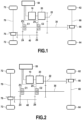
- This figure is a schematic view of a transmission system for a work vehicle such as an agricultural vehicle, for instance a tractor or a harvester combine.
- a work vehicle such as an agricultural vehicle, for instance a tractor or a harvester combine.
- the transmission comprises a prime mover 10 coupled with a gearbox 20.
- the prime mover 10 can for instance be a thermal engine, an electric engine or a hydraulic engine.
- the gearbox 20 is configured to provide an output through an output shaft 22 provided with gearings so as to provide the desired output.
- a primary shaft 30 is coupled to the output shaft 22 through gearings.
- This primary shaft 30 is coupled to a first axle 60 which is here represented as comprising two wheels 62 and 64 and an optional first differential 66 which couples the primary shaft 30 to the first axle 60.
- This first axle 60 is for instance the rear axle of a tractor, and is the driving axle of the vehicle.
- a secondary shaft 40 is selectively coupled to the primary shaft 30 through a first clutch C1 and a second clutch C2.
- the secondary shaft 40 is selectively coupled to the prime mover 10 through the first clutch C1 and the second clutch C2.
- This secondary shaft 40 is coupled through an optional second differential 76 to a second axle 70, which is here depicted with two wheels 72 and 74.
- This second axle 70 is for instance the front axle of a tractor.
- the second axle 70 is selectively coupled to the prime mover 10 through the first clutch C1 and the second clutch C2.
- a controller 50 is provided, which typically controls the prime mover 10, the first clutch C1 and the second clutch C2.
- the controller 50 may comprise a plurality of Electronic Control Units, commonly referred to as "ECUs".
- the prime mover 10, the first clutch C1 and the second clutch C2 can for instance be controlled by different ECUs from the controller 50, or by different controllers.
- the first clutch C1 and the second clutch C2 are piloted so as to selectively couple the secondary shaft 40 to the primary shaft 30.
- the first clutch C1 and the second clutch C2 have different reduction ratios, so as to enable different driving modes of the secondary shaft 40.
- the first clutch C1 can for instance be configured so that when it is engaged while the second clutch C2 is disengaged, the secondary shaft 40 is coupled to the primary shaft 30 so that the secondary shaft 40 and the primary shaft 30 present a proportional speed defined by among others the ratio Z3/Z4.
- Such a configuration can for instance be used when additional traction is required, so switch the vehicle to a 4 wheels drive mode.
- the second clutch C2 can for instance be configured so that when it is engaged while the first clutch C1 is disengaged, the secondary shaft 40 is coupled to the primary shaft 30 so that the second axle 40 presents a rotational speed that is proportional with the primary shaft 30, wherein the ratio is partially defined by Z5/Z6.
- the second axle 40 can then present a rotational speed that is higher than the rotational speed of the primary shaft 30, or for instance twice the rotational speed of the primary shaft 30.
- Such a configuration can for instance be used when a vehicle such as a tractor is required to make a steep turn. Indeed, during some work operations for a tractor or the like, the rotation is usually centered on one of the rear wheels, which therefore travels along a shorter path than the front wheels.
- the controller 50 is configured so as to selectively control the first clutch C1 and the second clutch C2 to be simultaneously engaged.
- Such a simultaneous engagement of both the first clutch C1 and the second clutch C2 will apply two different reduction ratios between the primary shaft 30 and the secondary shaft 40, and will therefore stop or prevent the rotation of the primary shaft 30 and of the secondary shaft 40, which results in an immobilization of the first axle 60 and of the second axle 70, which therefore enables to achieve a brake effect, for instance a parking brake effect.
- the controller 50 is configured to engage the first clutch C1 and the second clutch C2 so as to obtain a brake effect, for instance a parking brake effect.
- the first clutch C1 and the second clutch C2 are typically configured to resist to a defined torque, so as not to slide.
- the engagement of both the first clutch C1 and the second clutch C2 can be made either simultaneously or progressively.
- both the first clutch C1 and the second clutch C2 can be simultaneously engaged so as to prevent a displacement of the vehicle.
- both the first clutch C1 and the second clutch C2 can be simultaneously gradually engaged so as to apply a gradually increasing braking effect.
- the second clutch C2 can be gradually engaged so as to apply a gradually increasing brake effect, for instance until the second clutch C2 and the first clutch C1 are fully engaged so as to obtain a parking brake effect.
- the gradual engagement of the second clutch C2 will enable to obtain a potential service or emergency braking.
- the first clutch C1 can be gradually engaged so as to apply a gradually increasing brake effect, for instance until the second clutch C2 and the first clutch C1 are fully engaged so as to obtain a parking brake effect.
- the gradual engagement of the first clutch C1 will enable to obtain a potential service or emergency braking.
- Figure 2 presents a second embodiment of the invention.
- the first differential 66 of the first axle 60 (or the first axle 60 when provided without differential) is coupled to the output shaft 22 rather than to the primary shaft 30.
- the first axle 60 is therefore directly driven by the output shaft 22 of the gearbox 20.
- the first clutch C1 and second clutch C2 can selectively couple the primary shaft 30 to the secondary shaft 40.
- the primary shaft 30 and the secondary shaft 40 are immobilized; relative rotation of the primary shaft 30 and the secondary shaft 40 is prevented.
- the output shaft 22 of the gearbox 20 is also prevented from rotating since the primary shaft 30 and the output shaft 22 are coupled together through gearings.
- the present disclosure also relates to a control method for such a transmission.
- the control method can for instance comprise the operating modes described hereafter.
- both the first clutch and the second clutch are disengaged, such that only the first axle is driven by the prime mover 10.
- first clutch C1 In a first four wheels drive mode, only the first clutch C1 is engaged, so as to couple the second axle 70 to the prime mover 10 to drive the second axle 70 at a first rotational speed which is proportional with the first axle speed 60.
- a second four wheels drive mode only the second clutch C2 is engaged, so as to couple the second axle 70 to the prime mover 10 to drive the second axle 70 at a second rotational speed which is proportional with the first axle 60 but the ratio between axle speed is different than the previous case.
- the rotational speed of the second axle could be twice the first axle 60.
- the rotational speed of the second axle 70 is twice the rotational speed of the first axle 60.
- This second four wheels drive mode can typically be used for steep turning, for instance for a tractor.
- both the first clutch and the second clutch are engaged so that the second axle is coupled to the prime mover 10 through two distinct reduction ratios, which prevents relative rotation of the first and second axle, and therefore provides a brake effect such as a parking brake effect.
- This will be referred to as a braking mode.
- the braking mode can be used as a parking brake mode.
- First clutch C1 disengaged First clutch C1 engaged Second clutch C2 disengaged Two wheels drive mode First four wheels drive mode, with first ratio Second clutch C2 engaged Second four wheels drive mode, with second ratio Braking mode
- Such a system and associated method enables to optimize the use and functions of the system, thereby enabling to optimize the weight and volume of the transmission, or enabling to improve the reliability of the parking brake of the vehicle.
Landscapes
- Engineering & Computer Science (AREA)
- Mechanical Engineering (AREA)
- General Engineering & Computer Science (AREA)
- Chemical & Material Sciences (AREA)
- Combustion & Propulsion (AREA)
- Transportation (AREA)
- Arrangement And Driving Of Transmission Devices (AREA)
- Arrangement And Mounting Of Devices That Control Transmission Of Motive Force (AREA)
Abstract
Description
- The present invention relates to a braking device for an agricultural vehicle such as a tractor.
- Agricultural vehicles such as tractors usually operate in various driving modes, depending on their situation and work operation. Such multiple driving modes lead to a complex and voluminous structure. The present invention aims at optimizing such systems by implementing additional functions.
- The present invention aims at providing a solution to these technical issues.
- The present invention relates to a transmission system for an agricultural vehicle, comprising:
- a prime mover, for instance an engine,
- a first axle,
- a second axle,
- the first axle is a driving axle coupled to the prime mover,
- the second axle is selectively coupled to the prime mover through a first clutch and a second clutch, each configured to selectively couple the second axle to the prime mover,
- the first clutch and the second clutch having distinct reduction ratios,
- the system being characterized in that it comprises a controller, adapted to engage simultaneously both the first clutch and the second clutch so as to immobilize the first axle and second axle.
- In an example, the controller is configured to selectively:
- engage only the first clutch, so as to couple the second axle to the prime mover to drive the second axle at a first rotational speed which is proportional with the first axle speed by a first ratio,
- engage only the second clutch, so as to couple the second axle to the prime mover to drive the second axle at a second rotational speed which is proportional with the first axle speed by a second ratio distinct from the first ratio,
- engage neither the first clutch nor the second clutch, so that only the first axle is driven by the prime mover,
- engage both the first clutch and the second clutch, so that the second axle is coupled to the prime mover through two distinct reduction ratios.
- The second clutch can be configured such that when only the second clutch is engaged the second rotational speed of the second axle is different from the rotational speed of the first axle, for instance higher than the rotational speed of the first axle, for instance equal to twice the rotational speed of the first axle.
- The transmission can optionally comprise a primary shaft and a secondary shaft, wherein the primary shaft is coupled to the prime mover, the secondary shaft is selectively coupled to the primary shaft through the first clutch and the second clutch, and is coupled to the second axle.
- The first axle can be provided with a first differential. The second axle can be provided with a second differential.
- In an embodiment, the first axle can be coupled to the primary shaft through the first differential.
- The invention also relates to a tractor comprising the transmission system of any one of the preceding claims, wherein the first axle is the rear axle of the tractor and the second axle is the front axle of the tractor, or wherein the first axle is the front axle of the tractor and the second axle is the rear axle of the tractor.
- A control method for a transmission of an agricultural vehicle, said vehicle comprising an prime mover, a first axle, a second axle, wherein the first axle is a driving axle coupled to the prime mover, the second axle is selectively coupled to the prime mover through a first clutch and a second clutch, each configured to selectively couple the second axle to the prime mover, the first clutch and the second clutch having distinct reduction ratios,
the method being characterized in selectively initiating a braking mode of engaging both the first clutch and the second clutch, so as to immobilize the first axle and second axle. - In an embodiment, the method comprises steps of selectively initiating
- a two wheels drive mode, wherein both the first clutch and the second clutch are disengaged, such that only the first axle is driven by the prime mover;
- a first four wheels drive mode, wherein only the first clutch is engaged, so as to couple the second axle to the prime mover to drive the second axle at a first rotational speed which is proportional with the first axle speed,
- a second four wheels drive mode, wherein only the second clutch is engaged, so as to couple the second axle to the prime mover to drive the second axle at a second rotational speed which is proportional with the first axle speed but the ratio between axle speed is different than the previous case,
- a braking mode, wherein both the first clutch and the second clutch are engaged so that the second axle is coupled to the prime mover through two distinct reduction ratios, so as to immobilize both the first axle and the second axle.
- One of the four wheels drive mode could be used as a turning drive mode, the rotational speed of the second axle can for instance be twice that of the first axle.
- The invention and its advantages will be better understood upon reading the detailed description made here after of different embodiments of the invention, given by way of non-limiting examples. This description makes reference to the pages of appended drawings, in which:
- [
Fig. 1] Figure 1 presents a schematic drawing of an embodiment of the invention. - [
Fig. 2] Figure 2 presents a schematic drawing of another embodiment of the invention. - In all the figures, similar elements are designated by identical numerical references.
- A first example embodiment of the invention will then be described with reference to
figure 1 . - In the present text, by "coupled to", it is meant that two elements are coupled to each other, possibly through other intermediate elements. By contrast, "directly coupled to" is to be understood as indicating that there are no intermediate elements between two elements that are directly coupled to each other.
- This figure is a schematic view of a transmission system for a work vehicle such as an agricultural vehicle, for instance a tractor or a harvester combine.
- The transmission comprises a
prime mover 10 coupled with agearbox 20. Theprime mover 10 can for instance be a thermal engine, an electric engine or a hydraulic engine. - The
gearbox 20 is configured to provide an output through anoutput shaft 22 provided with gearings so as to provide the desired output. - A
primary shaft 30 is coupled to theoutput shaft 22 through gearings. Thisprimary shaft 30 is coupled to afirst axle 60 which is here represented as comprising twowheels first differential 66 which couples theprimary shaft 30 to thefirst axle 60. Thisfirst axle 60 is for instance the rear axle of a tractor, and is the driving axle of the vehicle. - A
secondary shaft 40 is selectively coupled to theprimary shaft 30 through a first clutch C1 and a second clutch C2. In other words, thesecondary shaft 40 is selectively coupled to theprime mover 10 through the first clutch C1 and the second clutch C2. - This
secondary shaft 40 is coupled through an optionalsecond differential 76 to asecond axle 70, which is here depicted with twowheels 72 and 74. Thissecond axle 70 is for instance the front axle of a tractor. In other words, thesecond axle 70 is selectively coupled to theprime mover 10 through the first clutch C1 and the second clutch C2. - A
controller 50 is provided, which typically controls theprime mover 10, the first clutch C1 and the second clutch C2. Thecontroller 50 may comprise a plurality of Electronic Control Units, commonly referred to as "ECUs". Theprime mover 10, the first clutch C1 and the second clutch C2 can for instance be controlled by different ECUs from thecontroller 50, or by different controllers. - The first clutch C1 and the second clutch C2 are piloted so as to selectively couple the
secondary shaft 40 to theprimary shaft 30. - When the first clutch C1 and the second clutch C2 are disengaged, the
primary shaft 30 and thesecondary shaft 40 are independent from each other, such that only theprimary shaft 30 is driven by theprime mover 10, and therefore only thefirst axle 60 is driven by theprime mover 10. - The first clutch C1 and the second clutch C2 have different reduction ratios, so as to enable different driving modes of the
secondary shaft 40. - For instance, if we consider that:
- the output of the first clutch C1 is through a gear wheel with a number of teeth equal to Z3, which cooperates with a gear wheel of the
secondary shaft 40 that presents a number of teeth equal to Z4, and - the output of the second clutch C2 is through a gear wheel with a number of teeth equal to Z5, which cooperates with a gear wheel of the
secondary shaft 40 that presents a number of teeth equal to Z6, - The first clutch C1 can for instance be configured so that when it is engaged while the second clutch C2 is disengaged, the
secondary shaft 40 is coupled to theprimary shaft 30 so that thesecondary shaft 40 and theprimary shaft 30 present a proportional speed defined by among others the ratio Z3/Z4. Such a configuration can for instance be used when additional traction is required, so switch the vehicle to a 4 wheels drive mode. - The second clutch C2 can for instance be configured so that when it is engaged while the first clutch C1 is disengaged, the
secondary shaft 40 is coupled to theprimary shaft 30 so that thesecond axle 40 presents a rotational speed that is proportional with theprimary shaft 30, wherein the ratio is partially defined by Z5/Z6. For instance, thesecond axle 40 can then present a rotational speed that is higher than the rotational speed of theprimary shaft 30, or for instance twice the rotational speed of theprimary shaft 30. Such a configuration can for instance be used when a vehicle such as a tractor is required to make a steep turn. Indeed, during some work operations for a tractor or the like, the rotation is usually centered on one of the rear wheels, which therefore travels along a shorter path than the front wheels. - In the claimed invention, the
controller 50 is configured so as to selectively control the first clutch C1 and the second clutch C2 to be simultaneously engaged. Such a simultaneous engagement of both the first clutch C1 and the second clutch C2 will apply two different reduction ratios between theprimary shaft 30 and thesecondary shaft 40, and will therefore stop or prevent the rotation of theprimary shaft 30 and of thesecondary shaft 40, which results in an immobilization of thefirst axle 60 and of thesecond axle 70, which therefore enables to achieve a brake effect, for instance a parking brake effect. - In other words, the
controller 50 is configured to engage the first clutch C1 and the second clutch C2 so as to obtain a brake effect, for instance a parking brake effect. - The first clutch C1 and the second clutch C2 are typically configured to resist to a defined torque, so as not to slide.
- The engagement of both the first clutch C1 and the second clutch C2 can be made either simultaneously or progressively.
- For instance, if we consider an initial situation where the vehicle is not moving, then both the first clutch C1 and the second clutch C2 can be simultaneously engaged so as to prevent a displacement of the vehicle.
- In addition, if the vehicle is moving, then both the first clutch C1 and the second clutch C2 can be simultaneously gradually engaged so as to apply a gradually increasing braking effect.
- Furthermore, if we consider for instance a working configuration where a single clutch is engaged, then the other clutch can be gradually engaged to apply a gradually increasing braking effect.
- For instance, if we consider that the vehicle is in a working configuration where only the first clutch C1 is engaged so as to obtain a four wheels drive configuration, then the second clutch C2 can be gradually engaged so as to apply a gradually increasing brake effect, for instance until the second clutch C2 and the first clutch C1 are fully engaged so as to obtain a parking brake effect. In this case, the gradual engagement of the second clutch C2 will enable to obtain a potential service or emergency braking.
- In a similar way, if we consider that the vehicle is in a configuration where only the second clutch C2 is engaged, for instance for a steep turning, then the first clutch C1 can be gradually engaged so as to apply a gradually increasing brake effect, for instance until the second clutch C2 and the first clutch C1 are fully engaged so as to obtain a parking brake effect. In this case, the gradual engagement of the first clutch C1 will enable to obtain a potential service or emergency braking.
-
Figure 2 presents a second embodiment of the invention. - This embodiment is similar to the one already described with reference to
figure 1 . Only the differences will be described here. - In this embodiment, the
first differential 66 of the first axle 60 (or thefirst axle 60 when provided without differential) is coupled to theoutput shaft 22 rather than to theprimary shaft 30. Thefirst axle 60 is therefore directly driven by theoutput shaft 22 of thegearbox 20. - The other functions remain unchanged. The first clutch C1 and second clutch C2 can selectively couple the
primary shaft 30 to thesecondary shaft 40. When both are engaged, theprimary shaft 30 and thesecondary shaft 40 are immobilized; relative rotation of theprimary shaft 30 and thesecondary shaft 40 is prevented. As theprimary shaft 30 is prevented from rotating, theoutput shaft 22 of thegearbox 20 is also prevented from rotating since theprimary shaft 30 and theoutput shaft 22 are coupled together through gearings. The configurations and functions described with reference tofigure 1 therefore also apply to this embodiment. - The present disclosure also relates to a control method for such a transmission.
- The control method can for instance comprise the operating modes described hereafter.
- In a two wheels drive mode, both the first clutch and the second clutch are disengaged, such that only the first axle is driven by the
prime mover 10. - In a first four wheels drive mode, only the first clutch C1 is engaged, so as to couple the
second axle 70 to theprime mover 10 to drive thesecond axle 70 at a first rotational speed which is proportional with thefirst axle speed 60. - In a second four wheels drive mode, only the second clutch C2 is engaged, so as to couple the
second axle 70 to theprime mover 10 to drive thesecond axle 70 at a second rotational speed which is proportional with thefirst axle 60 but the ratio between axle speed is different than the previous case. For instance, the rotational speed of the second axle could be twice thefirst axle 60. As a consequence, the rotational speed of thesecond axle 70 is twice the rotational speed of thefirst axle 60. This second four wheels drive mode can typically be used for steep turning, for instance for a tractor. - In a parking brake mode, emergency brake mode or service brake mode, both the first clutch and the second clutch are engaged so that the second axle is coupled to the
prime mover 10 through two distinct reduction ratios, which prevents relative rotation of the first and second axle, and therefore provides a brake effect such as a parking brake effect. This will be referred to as a braking mode. In some exemplary applications, the braking mode can be used as a parking brake mode. - The different operating modes are summarized in the table hereafter.
First clutch C1 disengaged First clutch C1 engaged Second clutch C2 disengaged Two wheels drive mode First four wheels drive mode, with first ratio Second clutch C2 engaged Second four wheels drive mode, with second ratio Braking mode - These different operating modes can be initiated by an operator or by a controller, for instance depending on controls or commands activated by the operator or depending on the working conditions of the vehicle.
- Such a system and associated method enables to optimize the use and functions of the system, thereby enabling to optimize the weight and volume of the transmission, or enabling to improve the reliability of the parking brake of the vehicle.
- Although the present invention has been described with reference to specific exemplary embodiments, it is obvious that modifications and changes can be carried out on these examples with departing from the general scope of the invention as defined by the claims. In particular, individual features of the different embodiments illustrated/mentioned can be combined into additional embodiments. Consequently, the description and the drawings must be considered in an illustrative, rather than a restrictive sense.
- It is also obvious that all the features described with reference to a method are transposable, alone or in combination, to a device, and conversely, all the features described with reference to a device are transposable, alone or in combination, to a method.
Claims (9)
- A transmission system for an agricultural vehicle, comprising:- a prime mover (10),- a first axle (60),- a second axle (70),whereinthe first axle (60) is a driving axle coupled to the prime mover (10),the second axle (70) is selectively coupled to the prime mover (10) through a first clutch (C1) and a second clutch (C2),the first clutch (C1) and the second clutch (C2) have distinct reduction ratios, the system is characterized in that it comprises a controller (50), adapted to engage simultaneously both the first clutch (C1) and the second clutch (C2) so as to immobilize the first axle (60) and second axle (70).
- The transmission system as defined in claim 1, wherein the controller (50) is configured to selectively:- engage only the first clutch (C1), so as to couple the second axle (70) to the prime mover (10) to drive the second axle (70) at a first rotational speed which is proportional to the speed of the first axle (60) by a first ratio,- engage only the second clutch (C2), so as to couple the second axle (70) to the prime mover (10) to drive the second axle (70) at a second rotational speed which is proportional to the speed of the first axle (60) by a second ratio distinct from the first ratio,- engage neither the first clutch (C1) nor the second clutch, so that only the first axle (60) is driven by the prime mover (10),- engage both the first clutch (C1) and the second clutch (C2), so that the second axle (70) is coupled to the prime mover (10) through two distinct reduction ratios.
- The transmission system as defined in claim 2, wherein the second clutch (C2) is configured such that when only the second clutch (C2) is engaged, the rotational speed of the second axle (70) is higher than the rotational speed of the first axle (60).
- The transmission system of any one of claims 1 to 3, which comprisesa primary shaft (30) and a secondary shaft (40),
whereinthe primary shaft (30) is coupled to the prime mover (10),the secondary shaft (40) is selectively coupled to the primary shaft (30) through the first clutch (C1) and the second clutch (C2), and is coupled to the second axle (70). - The transmission system of claim 4, wherein the first axle (60) is coupled to the primary shaft (30).
- A vehicle comprising the transmission system of any one of the preceding claims, wherein the first axle (60) is the rear axle of the vehicle and the second axle (70) is the front axle of the vehicle.
- A control method for a transmission of an agricultural vehicle, said vehicle comprising a prime mover (10), a first axle (60) provided, a second axle (70), wherein the first axle (60) is a driving axle coupled to the prime mover (10), the second axle (70) is selectively coupled to the prime mover (10) through a first clutch (C1) and a second clutch (C2), the first clutch (C1) and the second clutch (C2) having distinct reduction ratios,
the method being characterized in selectively initiating a braking mode of engaging both the first clutch (C1) and the second clutch (C2), so as to immobilize the first axle (60) and second axle (70). - The method of claim 7, further comprising steps of selectively initiating- a two wheels drive mode, wherein both the first clutch (C1) and the second clutch (C2) are disengaged, such that only the first axle (60) is driven by the prime mover;- a first four wheels drive mode, wherein only the first clutch (C1) is engaged, so as to couple the second axle (70) to the prime mover (10) to drive the second axle (70) at a first rotational speed which is a proportional speed of the first axle (60) defined by the ratio Z3/Z4,- a second four wheel drive mode, wherein only the second clutch (C2) is engaged, so as to couple the second axle (70) to the prime mover (10) to drive the second axle (70) at a second rotational speed which is proportional speed of the first axle (60) defined by the ratio Z5/Z6,- a braking mode, wherein both the first clutch (C1) and the second clutch (C2) are engaged so that the second axle (70) is coupled to the prime mover (10) through two distinct reduction ratios.
- The method of claim 6, wherein in second four wheel drive mode, the rotational speed of the second axle (70) is higher than the rotational speed of the first axle (60).
Priority Applications (1)
| Application Number | Priority Date | Filing Date | Title |
|---|---|---|---|
| EP23305353.7A EP4431765B1 (en) | 2023-03-15 | 2023-03-15 | Work vehicle |
Applications Claiming Priority (1)
| Application Number | Priority Date | Filing Date | Title |
|---|---|---|---|
| EP23305353.7A EP4431765B1 (en) | 2023-03-15 | 2023-03-15 | Work vehicle |
Publications (2)
| Publication Number | Publication Date |
|---|---|
| EP4431765A1 true EP4431765A1 (en) | 2024-09-18 |
| EP4431765B1 EP4431765B1 (en) | 2025-10-29 |
Family
ID=85778647
Family Applications (1)
| Application Number | Title | Priority Date | Filing Date |
|---|---|---|---|
| EP23305353.7A Active EP4431765B1 (en) | 2023-03-15 | 2023-03-15 | Work vehicle |
Country Status (1)
| Country | Link |
|---|---|
| EP (1) | EP4431765B1 (en) |
Citations (3)
| Publication number | Priority date | Publication date | Assignee | Title |
|---|---|---|---|---|
| DE102016116538A1 (en) * | 2016-09-05 | 2018-03-08 | Dr. Ing. H.C. F. Porsche Aktiengesellschaft | Drivetrain and motor vehicle and method |
| DE102017220667A1 (en) * | 2017-01-19 | 2018-07-19 | Deere & Company | MULTI-MODE DRIVE TRAVEL FOR WORKING VEHICLES FOR SELECTIVE POWER DISTRIBUTION BETWEEN AXES |
| WO2021247695A1 (en) * | 2020-06-04 | 2021-12-09 | Bendix Commercial Vehicle Systems Llc | Parking brake for an electric vehicle with multi-speed gearbox |
-
2023
- 2023-03-15 EP EP23305353.7A patent/EP4431765B1/en active Active
Patent Citations (3)
| Publication number | Priority date | Publication date | Assignee | Title |
|---|---|---|---|---|
| DE102016116538A1 (en) * | 2016-09-05 | 2018-03-08 | Dr. Ing. H.C. F. Porsche Aktiengesellschaft | Drivetrain and motor vehicle and method |
| DE102017220667A1 (en) * | 2017-01-19 | 2018-07-19 | Deere & Company | MULTI-MODE DRIVE TRAVEL FOR WORKING VEHICLES FOR SELECTIVE POWER DISTRIBUTION BETWEEN AXES |
| WO2021247695A1 (en) * | 2020-06-04 | 2021-12-09 | Bendix Commercial Vehicle Systems Llc | Parking brake for an electric vehicle with multi-speed gearbox |
Also Published As
| Publication number | Publication date |
|---|---|
| EP4431765B1 (en) | 2025-10-29 |
Similar Documents
| Publication | Publication Date | Title |
|---|---|---|
| US8523738B2 (en) | Method of shifting a tandem drive axle having an inter-axle differential | |
| EP2709886B1 (en) | Vehicle and method for operating a vehicle | |
| US3963085A (en) | Planetary four wheel drive system having plural modes of operation | |
| DE69003299T2 (en) | Control system for torque distribution in a four-wheel drive motor vehicle. | |
| US20120021864A1 (en) | Drive axle system having a clutching device | |
| EP4015871B1 (en) | Work vehicle | |
| JPS59176121A (en) | Front wheel drive control device for four-wheel drive vehicles | |
| DE102017204354B4 (en) | Method of operating an all-terrain vehicle with articulated steering | |
| EP2955418B1 (en) | A variator-assisted transmission | |
| EP4311713A2 (en) | Drive axle system and method of control | |
| US5054573A (en) | Vehicle with multiple driven axles | |
| JPS6320580Y2 (en) | ||
| EP4431765B1 (en) | Work vehicle | |
| US8290667B2 (en) | Method for the operation of a traveling power take-off shaft coupled to a driving motor | |
| JPS6076475A (en) | Control arrangement for agricultural tractor | |
| US8340880B2 (en) | System and method for automatically and independently controlling wheel torque or speed using wheel hubs having engagement/disengagement mechanisms integrated therewith | |
| US11852222B2 (en) | Transmission assembly for a vehicle | |
| DE112014005377T5 (en) | Drive system for a vehicle | |
| WO2013167145A1 (en) | A heavy road vehicle comprising an additional traction system | |
| JP2023065317A (en) | Powertrain, method of controlling powertrain, and vehicle | |
| US11046177B2 (en) | Control method for hydraulic assistance | |
| US5067935A (en) | Interaxle differential | |
| JP7819085B2 (en) | Continuously variable speed power transmission device for work vehicle and work vehicle | |
| DE102020001248A1 (en) | Method for determining a load applied to a drive train by a power consumer | |
| US5263905A (en) | Arrangement for driving two wheels of the same axle in rotation, with a regulation of their rotational speeds |
Legal Events
| Date | Code | Title | Description |
|---|---|---|---|
| PUAI | Public reference made under article 153(3) epc to a published international application that has entered the european phase |
Free format text: ORIGINAL CODE: 0009012 |
|
| STAA | Information on the status of an ep patent application or granted ep patent |
Free format text: STATUS: REQUEST FOR EXAMINATION WAS MADE |
|
| 17P | Request for examination filed |
Effective date: 20230315 |
|
| AK | Designated contracting states |
Kind code of ref document: A1 Designated state(s): AL AT BE BG CH CY CZ DE DK EE ES FI FR GB GR HR HU IE IS IT LI LT LU LV MC ME MK MT NL NO PL PT RO RS SE SI SK SM TR |
|
| STAA | Information on the status of an ep patent application or granted ep patent |
Free format text: STATUS: EXAMINATION IS IN PROGRESS |
|
| 17Q | First examination report despatched |
Effective date: 20250319 |
|
| GRAP | Despatch of communication of intention to grant a patent |
Free format text: ORIGINAL CODE: EPIDOSNIGR1 |
|
| STAA | Information on the status of an ep patent application or granted ep patent |
Free format text: STATUS: GRANT OF PATENT IS INTENDED |
|
| INTG | Intention to grant announced |
Effective date: 20250804 |
|
| GRAS | Grant fee paid |
Free format text: ORIGINAL CODE: EPIDOSNIGR3 |
|
| GRAA | (expected) grant |
Free format text: ORIGINAL CODE: 0009210 |
|
| STAA | Information on the status of an ep patent application or granted ep patent |
Free format text: STATUS: THE PATENT HAS BEEN GRANTED |
|
| AK | Designated contracting states |
Kind code of ref document: B1 Designated state(s): AL AT BE BG CH CY CZ DE DK EE ES FI FR GB GR HR HU IE IS IT LI LT LU LV MC ME MK MT NL NO PL PT RO RS SE SI SK SM TR |
|
| REG | Reference to a national code |
Ref country code: CH Ref legal event code: F10 Free format text: ST27 STATUS EVENT CODE: U-0-0-F10-F00 (AS PROVIDED BY THE NATIONAL OFFICE) Effective date: 20251029 Ref country code: GB Ref legal event code: FG4D |
|
| REG | Reference to a national code |
Ref country code: DE Ref legal event code: R096 Ref document number: 602023008033 Country of ref document: DE |
|
| REG | Reference to a national code |
Ref country code: IE Ref legal event code: FG4D |
|
| PGFP | Annual fee paid to national office [announced via postgrant information from national office to epo] |
Ref country code: FR Payment date: 20251215 Year of fee payment: 4 |
|
| REG | Reference to a national code |
Ref country code: NL Ref legal event code: MP Effective date: 20251029 |
|
| PG25 | Lapsed in a contracting state [announced via postgrant information from national office to epo] |
Ref country code: ES Free format text: LAPSE BECAUSE OF FAILURE TO SUBMIT A TRANSLATION OF THE DESCRIPTION OR TO PAY THE FEE WITHIN THE PRESCRIBED TIME-LIMIT Effective date: 20251029 |
|
| REG | Reference to a national code |
Ref country code: LT Ref legal event code: MG9D |
|
| PG25 | Lapsed in a contracting state [announced via postgrant information from national office to epo] |
Ref country code: NO Free format text: LAPSE BECAUSE OF FAILURE TO SUBMIT A TRANSLATION OF THE DESCRIPTION OR TO PAY THE FEE WITHIN THE PRESCRIBED TIME-LIMIT Effective date: 20260129 |
|
| PGFP | Annual fee paid to national office [announced via postgrant information from national office to epo] |
Ref country code: DE Payment date: 20260313 Year of fee payment: 4 |
|
| PG25 | Lapsed in a contracting state [announced via postgrant information from national office to epo] |
Ref country code: FI Free format text: LAPSE BECAUSE OF FAILURE TO SUBMIT A TRANSLATION OF THE DESCRIPTION OR TO PAY THE FEE WITHIN THE PRESCRIBED TIME-LIMIT Effective date: 20251029 Ref country code: AT Free format text: LAPSE BECAUSE OF FAILURE TO SUBMIT A TRANSLATION OF THE DESCRIPTION OR TO PAY THE FEE WITHIN THE PRESCRIBED TIME-LIMIT Effective date: 20251029 Ref country code: HR Free format text: LAPSE BECAUSE OF FAILURE TO SUBMIT A TRANSLATION OF THE DESCRIPTION OR TO PAY THE FEE WITHIN THE PRESCRIBED TIME-LIMIT Effective date: 20251029 |
|
| PGFP | Annual fee paid to national office [announced via postgrant information from national office to epo] |
Ref country code: AT Payment date: 20260301 Year of fee payment: 4 |
|
| REG | Reference to a national code |
Ref country code: AT Ref legal event code: MK05 Ref document number: 1851862 Country of ref document: AT Kind code of ref document: T Effective date: 20251029 |
|
| PG25 | Lapsed in a contracting state [announced via postgrant information from national office to epo] |
Ref country code: NL Free format text: LAPSE BECAUSE OF FAILURE TO SUBMIT A TRANSLATION OF THE DESCRIPTION OR TO PAY THE FEE WITHIN THE PRESCRIBED TIME-LIMIT Effective date: 20251029 |
|
| PG25 | Lapsed in a contracting state [announced via postgrant information from national office to epo] |
Ref country code: RS Free format text: LAPSE BECAUSE OF FAILURE TO SUBMIT A TRANSLATION OF THE DESCRIPTION OR TO PAY THE FEE WITHIN THE PRESCRIBED TIME-LIMIT Effective date: 20260129 |
|
| PG25 | Lapsed in a contracting state [announced via postgrant information from national office to epo] |
Ref country code: IS Free format text: LAPSE BECAUSE OF FAILURE TO SUBMIT A TRANSLATION OF THE DESCRIPTION OR TO PAY THE FEE WITHIN THE PRESCRIBED TIME-LIMIT Effective date: 20260228 |
|
| PG25 | Lapsed in a contracting state [announced via postgrant information from national office to epo] |
Ref country code: PT Free format text: LAPSE BECAUSE OF FAILURE TO SUBMIT A TRANSLATION OF THE DESCRIPTION OR TO PAY THE FEE WITHIN THE PRESCRIBED TIME-LIMIT Effective date: 20260302 |
|
| PG25 | Lapsed in a contracting state [announced via postgrant information from national office to epo] |
Ref country code: PL Free format text: LAPSE BECAUSE OF FAILURE TO SUBMIT A TRANSLATION OF THE DESCRIPTION OR TO PAY THE FEE WITHIN THE PRESCRIBED TIME-LIMIT Effective date: 20251029 |
|
| PG25 | Lapsed in a contracting state [announced via postgrant information from national office to epo] |
Ref country code: LV Free format text: LAPSE BECAUSE OF FAILURE TO SUBMIT A TRANSLATION OF THE DESCRIPTION OR TO PAY THE FEE WITHIN THE PRESCRIBED TIME-LIMIT Effective date: 20251029 |
|
| PG25 | Lapsed in a contracting state [announced via postgrant information from national office to epo] |
Ref country code: BG Free format text: LAPSE BECAUSE OF FAILURE TO SUBMIT A TRANSLATION OF THE DESCRIPTION OR TO PAY THE FEE WITHIN THE PRESCRIBED TIME-LIMIT Effective date: 20251029 |