EP4431764A1 - Driveline assembly for a work vehicle and work vehicle comprising the same - Google Patents
Driveline assembly for a work vehicle and work vehicle comprising the same Download PDFInfo
- Publication number
- EP4431764A1 EP4431764A1 EP24164300.6A EP24164300A EP4431764A1 EP 4431764 A1 EP4431764 A1 EP 4431764A1 EP 24164300 A EP24164300 A EP 24164300A EP 4431764 A1 EP4431764 A1 EP 4431764A1
- Authority
- EP
- European Patent Office
- Prior art keywords
- oil
- work vehicle
- oil sump
- stretch
- driveline
- Prior art date
- Legal status (The legal status is an assumption and is not a legal conclusion. Google has not performed a legal analysis and makes no representation as to the accuracy of the status listed.)
- Granted
Links
Images

Classifications
-
- F—MECHANICAL ENGINEERING; LIGHTING; HEATING; WEAPONS; BLASTING
- F16—ENGINEERING ELEMENTS AND UNITS; GENERAL MEASURES FOR PRODUCING AND MAINTAINING EFFECTIVE FUNCTIONING OF MACHINES OR INSTALLATIONS; THERMAL INSULATION IN GENERAL
- F16H—GEARING
- F16H57/00—General details of gearing
- F16H57/04—Features relating to lubrication or cooling or heating
- F16H57/0434—Features relating to lubrication or cooling or heating relating to lubrication supply, e.g. pumps; Pressure control
- F16H57/0443—Features relating to lubrication or cooling or heating relating to lubrication supply, e.g. pumps; Pressure control for supply of lubricant during tilt or high acceleration, e.g. problems related to the tilt or extreme acceleration of the transmission casing and the supply of lubricant under these conditions
-
- F—MECHANICAL ENGINEERING; LIGHTING; HEATING; WEAPONS; BLASTING
- F16—ENGINEERING ELEMENTS AND UNITS; GENERAL MEASURES FOR PRODUCING AND MAINTAINING EFFECTIVE FUNCTIONING OF MACHINES OR INSTALLATIONS; THERMAL INSULATION IN GENERAL
- F16H—GEARING
- F16H57/00—General details of gearing
- F16H57/02—Gearboxes; Mounting gearing therein
- F16H57/027—Gearboxes; Mounting gearing therein characterised by means for venting gearboxes, e.g. air breathers
-
- F—MECHANICAL ENGINEERING; LIGHTING; HEATING; WEAPONS; BLASTING
- F16—ENGINEERING ELEMENTS AND UNITS; GENERAL MEASURES FOR PRODUCING AND MAINTAINING EFFECTIVE FUNCTIONING OF MACHINES OR INSTALLATIONS; THERMAL INSULATION IN GENERAL
- F16H—GEARING
- F16H57/00—General details of gearing
- F16H57/04—Features relating to lubrication or cooling or heating
- F16H57/0434—Features relating to lubrication or cooling or heating relating to lubrication supply, e.g. pumps; Pressure control
- F16H57/0435—Pressure control for supplying lubricant; Circuits or valves therefor
-
- F—MECHANICAL ENGINEERING; LIGHTING; HEATING; WEAPONS; BLASTING
- F16—ENGINEERING ELEMENTS AND UNITS; GENERAL MEASURES FOR PRODUCING AND MAINTAINING EFFECTIVE FUNCTIONING OF MACHINES OR INSTALLATIONS; THERMAL INSULATION IN GENERAL
- F16H—GEARING
- F16H57/00—General details of gearing
- F16H57/04—Features relating to lubrication or cooling or heating
- F16H57/0434—Features relating to lubrication or cooling or heating relating to lubrication supply, e.g. pumps; Pressure control
- F16H57/0436—Pumps
- F16H57/0439—Pumps using multiple pumps with different power sources or a single pump with different power sources, e.g. one and the same pump may selectively be driven by either the engine or an electric motor
-
- F—MECHANICAL ENGINEERING; LIGHTING; HEATING; WEAPONS; BLASTING
- F16—ENGINEERING ELEMENTS AND UNITS; GENERAL MEASURES FOR PRODUCING AND MAINTAINING EFFECTIVE FUNCTIONING OF MACHINES OR INSTALLATIONS; THERMAL INSULATION IN GENERAL
- F16H—GEARING
- F16H57/00—General details of gearing
- F16H57/04—Features relating to lubrication or cooling or heating
- F16H57/045—Lubricant storage reservoirs, e.g. reservoirs in addition to a gear sump for collecting lubricant in the upper part of a gear case
Definitions
- the present invention concerns a driveline assembly for a work vehicle and a work vehicle comprising a driveline assembly.
- Work vehicles comprising a main body, a locomotion system including wheels or tracks for moving the main body with respect to the ground, a propulsion system including a thermal engine and/or an electric motor, and a driveline, which operatively connects the locomotion system to the propulsion system.
- the drivelines comprise a plurality of mechanical components (e.g., gears and bearings), which are lubricated to reduce friction and wear between their contact surfaces.
- known work vehicles comprise an oil sump, which contains oil and a pump adapted to suck oil from the oil sump and to sprinkle it onto contact surfaces of the mechanical components.
- the oil sump is also adapted to collect the oil that falls due to gravity after lubricating the mechanical components.
- the drivelines may be lubricated by oil splashing, i.e., by splashing caused by the movement of the mechanical components.
- oil splashing i.e., by splashing caused by the movement of the mechanical components.
- the mechanical components of the drivelines are partially immersed in the oil sump.
- the free surface of the oil in the oil sump is substantially parallel to the ground.
- the oil redistributes because of gravity.
- the free surface of the oil is still substantially parallel to the ground, but the oil accumulates on a portion of the oil sump oriented towards a downmost part of the inclined road.
- the suction of the oil by means of the pump may be problematic and the lubrication of the driveline could be negatively affected.
- the oil accumulated in the downmost portion of the oil sump may not be fluidly connected with an inlet of the pump and, therefore, may not be sucked.
- the oil may be positioned below the inlet of the pump with respect to a vertical axis of the vehicle.
- numeral 10 indicates a work vehicle, in particular an agricultural vehicle such as a tractor.
- Work vehicle 10 comprises a main body 11, a plurality of wheels 12, which are rotatable relative to main body 11 about respective rotational axes and motor means 13 (e.g., a thermal engine and/or an electric motor) adapted to rotate wheels 12 about their respective rotational axes.
- motor means 13 e.g., a thermal engine and/or an electric motor
- Work vehicle 10 defines a longitudinal direction X, a front portion 10a and a rear portion 10b according to longitudinal direction X.
- front portion 10a and rear portion 10b are opposite to each other according to longitudinal direction X.
- a forward advancement direction A of work vehicle 10 is oriented from rear portion 10b towards front portion 10a ( Figures 2A, 2B and 2C ).
- Work vehicle 10 further comprises a driveline assembly 1.
- Driveline assembly 1 comprises, in turn, a driveline 2 adapted to operatively connect motor means 13 to wheels 12 and an oil sump 3 for collecting by gravity an oil 60 adapted to lubricate driveline 2.
- Driveline 2 comprises a plurality of mechanical components - which are known per se and not shown - adapted to transmit motion from motor means 13 to wheels 12.
- driveline 2 comprises a plurality of wheels and bearings.
- at least some of the mechanical components are at least partially immersed in oil 60 contained in oil sump 3.
- Drivelines assembly 1 also comprises a pumping system 8, which is adapted to suck oil 60 from oil sump 3 and to direct it to the mechanical components of driveline 2 to be lubricated.
- pumping system 8 comprises a pump 80, which is arranged within oil sump 3 ( Figures 2A, 2B and 2C ).
- Driveline assembly 1 also comprises a container 5 enclosing at least in part driveline 2.
- container 5 comprises oil sump 3 or is defined at least in part by oil sump 3.
- oil sump 3 constitutes the lowermost portion of container 5 according to a direction V vertical to the ground on which wheels 12 rest, i.e., the portion of container 5 closest to the ground.
- Figures 2A, 2B and 2C show a plane G tangent to the ground on which wheels 12 rest and direction V is perpendicular to plane G.
- driveline assembly 1 comprises an oil reservoir 4 adapted to contain oil 60, fluidly connected to oil sump 3 and arranged at least in part below oil sump 3 according to direction V.
- oil reservoir 4 is adapted to contain the same oil contained in oil sump 3.
- oil reservoir 4 is closer to the ground on which wheels 12 rest than oil sump 3.
- oil reservoir 4 is arranged at least in part below driveline 2 according to direction V.
- Oil reservoir 4 is arranged externally to container 5. Therefore, the mechanical components of driveline 2 are not immersed in oil 60 contained in oil reservoir 4.
- oil reservoir 4 is at least partially interposed between oil sump 3 and front portion 10a along longitudinal direction X. In the embodiment shown, oil reservoir 4 is completely interposed between oil sump 3 and front portion 10a along longitudinal direction X.
- oil reservoir 4 comprises a vent 9 for the purpose of releasing any aeriform substances contained within oil reservoir 4 (by way of example, air or oil vapors) to the outside of driveline assembly 1.
- driveline assembly 1 comprises a duct 6 fluidly connecting oil sump 3 to oil reservoir 4. Accordingly, oil 60 contained in oil sump 3 is adapted flow to oil reservoir 4 through duct 6 due to gravity.
- Figures 2A, 2B and 2C show driveline assembly 1 respectively in a flat condition, an uphill condition and a downhill condition.
- driveline assembly 1 is in the flat condition when work vehicle 1 is on a flat road, i.e., a road perpendicular or substantially perpendicular to acceleration vector g; driveline assembly 1 is in the uphill condition or the downhill condition respectively when work vehicle 1 is on a uphill road or a downhill road.
- a free surface 61 of oil 60 in oil sump 3 is directed perpendicularly to acceleration vector g.
- the acceleration vector g to be considered is the one acting on driveline assembly 1 or work vehicle 10.
- the acceleration vector g is applied in the center of mass of work vehicle 10.
- oil reservoir 4 when driveline assembly 1 is in the flat condition or the downhill condition, oil reservoir 4 is completely full; when driveline assembly 1 is in the uphill condition, oil 60 from oil reservoir 4 is adapted to flow to oil sump 3 because of gravity.
- Figure 2B further shows a dashed line, which represents the free surface of oil 60 in a theoretical condition, in which driveline assembly does not comprise oil reservoir 4.
- the level of oil in the theoretical condition is lower than free surface 61 according to the invention and pump 80 is arranged in part above the dashed line.
- the total amount of oil 60 contained in driveline assembly 1 is such that the oil level in oil sump 3 when driveline assembly 1 is in the flat condition is the same as in the theoretical condition, in which the driveline assembly 1 does not include oil reservoir 4.
- Work vehicle 1 further comprises at least one implement 50, which is hydraulically operated and an actuation circuit 51 for the actuation of implement 50.
- implement 50 is a front end loader.
- the actuation circuit 51 comprises, in turn, a pump 52 adapted to suck oil from oil sump 3, a remote valve 20 fluidly connected to pump 52, the implement 50 fluidly connected to remote valve 20 and a duct 7 fluidly connecting remote valve 20 to driveline assembly 1 ( Figure 1 ).
- Pump 52 is adapted to deliver the oil sucked from oil sump 3 to remote valve 20. Moreover, as schematically shown in Figure 2 , pump 52 is arranged within oil sump 3.
- actuation circuit 51 further comprises in succession a stretch 24a fluidly connecting pump 52 to remote valve 20, a stretch 24b fluidly connecting remote valve 20 to implement 50 and a stretch 24c fluidly connecting implement 50 to remote valve 20.
- Duct 7 comprises a stretch 21 extending from remote valve 20, a stretch 22 fluidly connecting stretch 21 to oil sump 3 and a stretch 23 fluidly connecting stretch 21 to oil reservoir 4.
- stretches 21, 22 and 23 are jointed with one another by a T-connection or a three-way fitting.
- Figures 2A, 2B, 2C show that pump 52 is completely immersed in oil 60 in the flat condition, the uphill condition and the downhill condition.
- driveline assembly 1 comprises valve means adapted to selectively control the flow of oil between stretch 21 and oil sump 3 and/or between stretch 21 and oil reservoir 4.
- the valve means are arranged at duct 7 and comprise a hydraulically actuated valve or an electro-hydraulically actuated valve.
- valve means are adapted to control the flow of oil such that the flow rate of oil flowing between stretch 21 and oil reservoir 4 is greater than the flow rate of oil flowing between stretch 21 and oil sump 3.
- valve means may be adapted to completely deny the fluidic communication between stretch 21 and oil sump 3 and allow the fluidic communication between stretch 21 and oil reservoir 4.
- cross section shall mean the section of the duct 6, 7 perpendicular to the longitudinal direction of the same duct 6, 7.
- actuation circuit 51 comprises deaeration means 53 adapted to remove oxygen and other dissolved gases from the oil flowing through it.
- actuation circuit 51 comprises a deaerator 54 at stretch 22 and/or a deaerator 55 at stretch 23.
- driveline assembly 1 and work vehicle 10 The operation of driveline assembly 1 and work vehicle 10 according to the present invention is described in the following.
- oil 60 of driveline assembly 1 is contained in part in oil sump 3 and in part in oil reservoir 4.
- driveline 2 transmits motion from motor means 13 to wheels 12 and the mechanical components of driveline 2 are lubricated by oil splashing and pumping system 8.
- the mechanical components of driveline 2 are partially immersed in oil 60 contained in oil sump 3 and lubricate the contact surfaces thereof by virtue of their movements.
- pumping system 8 sucks oil 60 from oil sump 3 and sprays it towards the mechanical components of driveline 2.
- oil After lubricating the surfaces of mechanical components, the oil falls by gravity and is collected by oil sump 3. In addition, in the flat condition and the downhill condition, the oil flows from oil sump 3 to oil reservoir 4 through duct 6 due to gravity.
- pump 52 sucks oil 60 from oil sump 3 and delivers it to remote valve 20.
- Remote valve 20 delivers the sucked oil to implement 50.
- oil flows from pump 52 to remote valve 20 through stretch 24a and from remote valve 20 to implement 50 through stretch 24b.
- driveline assembly 1 comprises oil reservoir 4, pumps 52 and 80 are completely immersed in oil in the flat condition ( Figure 2A ), the uphill condition ( Figure 2B ) and the downhill condition ( Figure 2C ).
- oil 60 flows from oil reservoir 4 to oil sump 3 through duct 6 because of gravity and thus ensures that the inlets of both pumps 52 and 80 are completely immersed in lubricating oil 60.
- valve means control the flow of oil flowing between stretch 21 and oil sump 3 and/or between stretch 21 and oil reservoir 4.
- driveline assembly 1 comprises oil reservoir 4, which is connected to oil sump 3 and arranged below oil sump 3, the oil capacity of driveline assembly 1 is increased and the lubrication quality of the mechanical components of driveline 2 is increased, especially when work vehicle is positioned on an inclined road.
- the total oil capacity of driveline assembly 1 is increased without causing an increase in power losses, because the oil capacity of oil sump 3 needs not be increased with respect to the oil sumps of the known work vehicles.
- oil reservoir 4 comprises vent 9
- oil 60 can flow between oil sump 3 and oil reservoir 4 by gravity without the risk of obstruction due to any aeriform substances inside oil reservoir 4.
- driveline assembly 1 comprises duct 7, which fluidly connects remote valve 20 to oil sump 3 and oil reservoir 4, the oil flow from remote valve 20 is split between oil sump 3 and oil reservoir 4. This allows the velocity of the flow coming from remote valve 20 and directed to oil sump 3 to be reduced. As a result, turbulence and aeration of oil 60 is limited. In particular, oil reservoir 4 allows oil 60 to stagnate and to be deaerated. This effect can be enhanced by causing the oil flow rate directed to oil reservoir 4 to be much greater than the oil flow rate directed to oil sump 3.
- work vehicle 10 might comprise tracks instead of wheels 12.
- Work vehicle 10 might comprise more than one implement 50 and more than one actuation circuits 51.
Landscapes
- Engineering & Computer Science (AREA)
- General Engineering & Computer Science (AREA)
- Mechanical Engineering (AREA)
- General Details Of Gearings (AREA)
- Motor Power Transmission Devices (AREA)
Abstract
Description
- The present invention concerns a driveline assembly for a work vehicle and a work vehicle comprising a driveline assembly.
- Work vehicles are known comprising a main body, a locomotion system including wheels or tracks for moving the main body with respect to the ground, a propulsion system including a thermal engine and/or an electric motor, and a driveline, which operatively connects the locomotion system to the propulsion system.
- In general, the drivelines comprise a plurality of mechanical components (e.g., gears and bearings), which are lubricated to reduce friction and wear between their contact surfaces. For this purpose, known work vehicles comprise an oil sump, which contains oil and a pump adapted to suck oil from the oil sump and to sprinkle it onto contact surfaces of the mechanical components. The oil sump is also adapted to collect the oil that falls due to gravity after lubricating the mechanical components.
- At the same time the drivelines may be lubricated by oil splashing, i.e., by splashing caused by the movement of the mechanical components. For this purpose, the mechanical components of the drivelines are partially immersed in the oil sump.
- However, such lubrication methods are not optimal under all vehicle operating conditions.
- As known, when the work vehicle is positioned on a flat road, the free surface of the oil in the oil sump is substantially parallel to the ground. When the work vehicle is positioned on an inclined road, the oil redistributes because of gravity. In detail, the free surface of the oil is still substantially parallel to the ground, but the oil accumulates on a portion of the oil sump oriented towards a downmost part of the inclined road.
- In this condition, the suction of the oil by means of the pump may be problematic and the lubrication of the driveline could be negatively affected. In fact, the oil accumulated in the downmost portion of the oil sump may not be fluidly connected with an inlet of the pump and, therefore, may not be sucked. In detail, the oil may be positioned below the inlet of the pump with respect to a vertical axis of the vehicle.
- In order to ensure a correct suction of the oil, it might be desirable to increase the amount of oil in the oil sump. In fact, an oil sump containing a greater amount of oil would minimize the risk of the pump not being capable of sucking the oil. However, the capacity of oil of the drivelines is limited by the fact that as the amount of oil increases, the power losses increase, as a consequence of the fact that the oil level in the oil sump rises and the portion of the mechanical components immersed in the oil increases.
- Therefore, there is a need within the industry for a driveline assembly for a work vehicle allowing the quality of lubrication of the mechanical components of the driveline to be efficiently ensured even when the work vehicle is positioned on an inclined road.
- The aforementioned aim is reached by a driveline assembly for a work vehicle, as claimed in the appended independent claim.
- Preferred embodiments of the invention are realized according to the claims dependent or related to the above independent claim.
- For a better understanding of the present invention, one preferred embodiment is described in the following, by way of a non-limiting example, with reference to the attached drawings wherein:
-
Figure 1 is a schematic representation of a work vehicle comprising a driveline assembly according to the present invention; and -
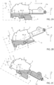
Figures 2A, 2B and 2C are lateral and schematic views of the driveline assembly ofFigure 1 in three respective different operating conditions and with parts removed for clarity. - With reference to
figure 1 ,numeral 10 indicates a work vehicle, in particular an agricultural vehicle such as a tractor. -
Work vehicle 10 comprises amain body 11, a plurality ofwheels 12, which are rotatable relative tomain body 11 about respective rotational axes and motor means 13 (e.g., a thermal engine and/or an electric motor) adapted to rotatewheels 12 about their respective rotational axes. -
Work vehicle 10 defines a longitudinal direction X, afront portion 10a and arear portion 10b according to longitudinal direction X. In detail,front portion 10a andrear portion 10b are opposite to each other according to longitudinal direction X. In addition, a forward advancement direction A ofwork vehicle 10 is oriented fromrear portion 10b towardsfront portion 10a (Figures 2A, 2B and 2C ). -
Work vehicle 10 further comprises adriveline assembly 1.Driveline assembly 1 comprises, in turn, adriveline 2 adapted to operatively connect motor means 13 towheels 12 and anoil sump 3 for collecting by gravity anoil 60 adapted tolubricate driveline 2. -
Driveline 2 comprises a plurality of mechanical components - which are known per se and not shown - adapted to transmit motion from motor means 13 towheels 12. By way of example,driveline 2 comprises a plurality of wheels and bearings. Preferably, at least some of the mechanical components are at least partially immersed inoil 60 contained inoil sump 3. -
Drivelines assembly 1 also comprises apumping system 8, which is adapted to suckoil 60 fromoil sump 3 and to direct it to the mechanical components ofdriveline 2 to be lubricated. In the embodiment shown,pumping system 8 comprises a pump 80, which is arranged within oil sump 3 (Figures 2A, 2B and 2C ). -
Driveline assembly 1 also comprises acontainer 5 enclosing at least inpart driveline 2. In addition,container 5 comprisesoil sump 3 or is defined at least in part byoil sump 3. Preferably but not necessarily,oil sump 3 constitutes the lowermost portion ofcontainer 5 according to a direction V vertical to the ground on whichwheels 12 rest, i.e., the portion ofcontainer 5 closest to the ground. In particular,Figures 2A, 2B and 2C show a plane G tangent to the ground on whichwheels 12 rest and direction V is perpendicular to plane G. - Advantageously,
driveline assembly 1 comprises anoil reservoir 4 adapted to containoil 60, fluidly connected tooil sump 3 and arranged at least in part belowoil sump 3 according to direction V. In particular,oil reservoir 4 is adapted to contain the same oil contained inoil sump 3. - In other words,
oil reservoir 4 is closer to the ground on whichwheels 12 rest thanoil sump 3. In addition,oil reservoir 4 is arranged at least in part belowdriveline 2 according to direction V. -
Oil reservoir 4 is arranged externally tocontainer 5. Therefore, the mechanical components ofdriveline 2 are not immersed inoil 60 contained inoil reservoir 4. - More in detail,
oil reservoir 4 is at least partially interposed betweenoil sump 3 andfront portion 10a along longitudinal direction X. In the embodiment shown,oil reservoir 4 is completely interposed betweenoil sump 3 andfront portion 10a along longitudinal direction X. - Furthermore, as schematized in
Figure 1 ,oil reservoir 4 comprises avent 9 for the purpose of releasing any aeriform substances contained within oil reservoir 4 (by way of example, air or oil vapors) to the outside ofdriveline assembly 1. - In detail,
driveline assembly 1 comprises aduct 6 fluidly connectingoil sump 3 tooil reservoir 4. Accordingly,oil 60 contained inoil sump 3 is adapted flow tooil reservoir 4 throughduct 6 due to gravity. -
Figures 2A, 2B and 2C showdriveline assembly 1 respectively in a flat condition, an uphill condition and a downhill condition. In particular,driveline assembly 1 is in the flat condition whenwork vehicle 1 is on a flat road, i.e., a road perpendicular or substantially perpendicular to acceleration vector g;driveline assembly 1 is in the uphill condition or the downhill condition respectively whenwork vehicle 1 is on a uphill road or a downhill road. - In the three conditions shown in
Figures 2A, 2B and 2C , afree surface 61 ofoil 60 inoil sump 3 is directed perpendicularly to acceleration vector g. Specifically, the acceleration vector g to be considered is the one acting ondriveline assembly 1 orwork vehicle 10. For example, the acceleration vector g is applied in the center of mass ofwork vehicle 10. - When
driveline assembly 1 is in the flat condition,free surface 61 ofoil 60 inoil sump 3 is perpendicular to vector g and parallel to plane G (Figure 2A ); whendriveline assembly 1 is in the uphill condition or the downhill condition,free surface 61 ofoil 60 inoil sump 3 is still perpendicular to vector g and angled with respect to plane G (Figures 2B and 2C ). In addition, consideringfree surface 61,Figures 2A, 2B, 2C show that pump 80 is completely immersed inoil 60 in the flat condition, the uphill condition and the downhill condition. - In the embodiment shown, when
driveline assembly 1 is in the flat condition or the downhill condition,oil reservoir 4 is completely full; whendriveline assembly 1 is in the uphill condition,oil 60 fromoil reservoir 4 is adapted to flow tooil sump 3 because of gravity. -
Figure 2B further shows a dashed line, which represents the free surface ofoil 60 in a theoretical condition, in which driveline assembly does not compriseoil reservoir 4. In further detail, as schematized inFigure 2B , the level of oil in the theoretical condition is lower thanfree surface 61 according to the invention and pump 80 is arranged in part above the dashed line. - Preferably, the total amount of
oil 60 contained indriveline assembly 1 is such that the oil level inoil sump 3 whendriveline assembly 1 is in the flat condition is the same as in the theoretical condition, in which thedriveline assembly 1 does not includeoil reservoir 4. -
Work vehicle 1 further comprises at least one implement 50, which is hydraulically operated and anactuation circuit 51 for the actuation of implement 50. By way of example, implement 50 is a front end loader. - The
actuation circuit 51 comprises, in turn, apump 52 adapted to suck oil fromoil sump 3, aremote valve 20 fluidly connected to pump 52, the implement 50 fluidly connected toremote valve 20 and aduct 7 fluidly connectingremote valve 20 to driveline assembly 1 (Figure 1 ). -
Pump 52 is adapted to deliver the oil sucked fromoil sump 3 toremote valve 20. Moreover, as schematically shown inFigure 2 , pump 52 is arranged withinoil sump 3. - As schematized in
Figure 1 ,actuation circuit 51 further comprises in succession astretch 24a fluidly connectingpump 52 toremote valve 20, astretch 24b fluidly connectingremote valve 20 to implement 50 and a stretch 24c fluidly connecting implement 50 toremote valve 20. -
Duct 7 comprises astretch 21 extending fromremote valve 20, astretch 22 fluidly connectingstretch 21 tooil sump 3 and astretch 23 fluidly connectingstretch 21 tooil reservoir 4. In detail, stretches 21, 22 and 23 are jointed with one another by a T-connection or a three-way fitting. - Moreover, considering
free surface 61,Figures 2A, 2B, 2C show that pump 52 is completely immersed inoil 60 in the flat condition, the uphill condition and the downhill condition. - According to a not-shown embodiment,
driveline assembly 1 comprises valve means adapted to selectively control the flow of oil betweenstretch 21 andoil sump 3 and/or betweenstretch 21 andoil reservoir 4. In particular, the valve means are arranged atduct 7 and comprise a hydraulically actuated valve or an electro-hydraulically actuated valve. - In detail, the valve means are adapted to control the flow of oil such that the flow rate of oil flowing between
stretch 21 andoil reservoir 4 is greater than the flow rate of oil flowing betweenstretch 21 andoil sump 3. In further detail, the valve means may be adapted to completely deny the fluidic communication betweenstretch 21 andoil sump 3 and allow the fluidic communication betweenstretch 21 andoil reservoir 4. - Furthermore, the extension of the cross section of
duct 6 is greater than the extension of the cross section ofduct 7. In detail, cross section shall mean the section of theduct same duct - Preferably,
actuation circuit 51 comprises deaeration means 53 adapted to remove oxygen and other dissolved gases from the oil flowing through it. In detail,actuation circuit 51 comprises adeaerator 54 atstretch 22 and/or adeaerator 55 atstretch 23. - The operation of
driveline assembly 1 andwork vehicle 10 according to the present invention is described in the following. - In use,
oil 60 ofdriveline assembly 1 is contained in part inoil sump 3 and in part inoil reservoir 4. - During operation,
driveline 2 transmits motion from motor means 13 towheels 12 and the mechanical components ofdriveline 2 are lubricated by oil splashing andpumping system 8. In particular, at least some of the mechanical components ofdriveline 2 are partially immersed inoil 60 contained inoil sump 3 and lubricate the contact surfaces thereof by virtue of their movements. - At the same time,
pumping system 8 sucksoil 60 fromoil sump 3 and sprays it towards the mechanical components ofdriveline 2. - After lubricating the surfaces of mechanical components, the oil falls by gravity and is collected by
oil sump 3. In addition, in the flat condition and the downhill condition, the oil flows fromoil sump 3 tooil reservoir 4 throughduct 6 due to gravity. - At the same time, pump 52 sucks
oil 60 fromoil sump 3 and delivers it toremote valve 20.Remote valve 20, in turn, delivers the sucked oil to implement 50. In detail, oil flows frompump 52 toremote valve 20 throughstretch 24a and fromremote valve 20 to implement 50 throughstretch 24b. - After actuating implement 50, the oil flows back to
remote valve 20 through stretch 24c and then towardsoil sump 3 throughstretch 22 andoil reservoir 4 throughstretch 23. - In detail, since
driveline assembly 1 comprisesoil reservoir 4, pumps 52 and 80 are completely immersed in oil in the flat condition (Figure 2A ), the uphill condition (Figure 2B ) and the downhill condition (Figure 2C ). In further detail, whendriveline assembly 1 is in the uphill condition,oil 60 flows fromoil reservoir 4 tooil sump 3 throughduct 6 because of gravity and thus ensures that the inlets of bothpumps 52 and 80 are completely immersed in lubricatingoil 60. - In the not-shown embodiment comprising the valve means, valve means control the flow of oil flowing between
stretch 21 andoil sump 3 and/or betweenstretch 21 andoil reservoir 4. - In view of the foregoing, the advantages of
driveline assembly 1 andwork vehicle 10 according to the invention are apparent. - In detail, since
driveline assembly 1 comprisesoil reservoir 4, which is connected tooil sump 3 and arranged belowoil sump 3, the oil capacity ofdriveline assembly 1 is increased and the lubrication quality of the mechanical components ofdriveline 2 is increased, especially when work vehicle is positioned on an inclined road. In addition, the total oil capacity ofdriveline assembly 1 is increased without causing an increase in power losses, because the oil capacity ofoil sump 3 needs not be increased with respect to the oil sumps of the known work vehicles. - Since
oil reservoir 4 comprisesvent 9,oil 60 can flow betweenoil sump 3 andoil reservoir 4 by gravity without the risk of obstruction due to any aeriform substances insideoil reservoir 4. - Since
driveline assembly 1 comprisesduct 7, which fluidly connectsremote valve 20 tooil sump 3 andoil reservoir 4, the oil flow fromremote valve 20 is split betweenoil sump 3 andoil reservoir 4. This allows the velocity of the flow coming fromremote valve 20 and directed tooil sump 3 to be reduced. As a result, turbulence and aeration ofoil 60 is limited. In particular,oil reservoir 4 allowsoil 60 to stagnate and to be deaerated. This effect can be enhanced by causing the oil flow rate directed tooil reservoir 4 to be much greater than the oil flow rate directed tooil sump 3. - In addition, since the extension of the cross section of
duct 6 is greater than the extension of the cross section ofduct 7, the velocity ofoil 60 flowing betweenoil reservoir 4 andoil sump 3 throughduct 6 is significantly reduced. This allows turbulence and aeration ofoil 60 to be further limited. - It is clear that modifications can be made to
driveline assembly 1 andwork vehicle 10 which do not extend beyond the scope of protection defined by the claims. - In particular,
work vehicle 10 might comprise tracks instead ofwheels 12. -
Work vehicle 10 might comprise more than one implement 50 and more than oneactuation circuits 51.
Claims (15)
- Driveline assembly (1) for a work vehicle (10), comprising:- a driveline (2) adapted to operatively connect motor means (13) of said work vehicle (10) to locomotion means (12) of said work vehicle (10);- an oil sump (3) adapted to collect an oil (60) lubricating, in use, said driveline (2);- at least a pump (80, 52) adapted to suck said oil (60) from said oil sump (3) and arranged within said oil sump (3);- an oil reservoir (4) adapted to contain said oil (60);
wherein said oil reservoir (4) is fluidly connected to said oil sump (3) and arranged at least in part below said oil sump (3) according to a direction (V) orthogonal to the ground on which said locomotion means (12), in use, rest. - Driveline assembly according to claim 1, comprising a container (5) enclosing at least in part said driveline (2);said container (5) enclosing said oil sump (3) or defined at least in part by said oil sump (3);wherein said oil reservoir (4) is arranged externally to said container (5).
- Driveline assembly according to claim 1 or 2, comprising a first duct (6) fluidly connecting said oil sump (3) to said oil reservoir (4).
- Driveline assembly according to any one of the foregoing claims, wherein said oil reservoir (4) comprises a vent (9).
- Driveline assembly according to any one of the foregoing claims, comprising a first said pump (80) adapted to suck said oil (60) from said oil sump (3) to lubricate said driveline (2).
- Work vehicle (10) comprising:- a main body (11);- locomotion means (12) adapted to move said main body (11) with respect to a reference system;- motor means (13) adapted to drive said locomotion means (12); and- a driveline assembly (1) according to any one of the foregoing claims.
- Work vehicle according to claim 6, comprising:- at least one implement (50), which is hydraulically operated, in use;- an actuation circuit (51) for the actuation of said implement (50);said actuation circuit (51) comprising:- a second said pump (52) adapted to suck said oil (60) from said oil sump (3);- a remote valve (20) fluidly connected to said second pump (52) and said implement (50);- a second duct (7) fluidly connecting said remote valve (20) to said driveline assembly (1);said second pump (52) being adapted to deliver, in use, said oil sucked from said oil sump (3) to said remote valve (20) .
- Work vehicle according to claim 7, wherein said second duct (7) comprises:- a first stretch (21) extending from said remote valve (20) ;- a second stretch (22) fluidly connecting said first stretch (21) to said oil sump (3); and- a third stretch (23) fluidly connecting said first stretch (21) to said oil reservoir (4).
- Work vehicle according to claim 8, comprising valve means adapted to control the flow of oil between said first stretch (21) and said oil sump (3) and/or between said first stretch (21) and said oil reservoir (4).
- Work vehicle according to claim 9, wherein said valve means are adapted to control the flow of oil such that the flow rate of said oil flowing, in use, between said first stretch (21) and said oil reservoir (4) is greater than the flow rate of said oil flowing, in use, between said first stretch (21) and said oil sump (3).
- Work vehicle according to claim 9 or 10, wherein said valve means comprise a hydraulically actuated valve or an electro-hydraulically actuated valve.
- Work vehicle according to any one of claims 7 to 11, when depending on claim 3, wherein the extension of the cross section of said first duct (6) is greater than the extension of the cross section of said second duct (7).
- Work vehicle according to any one of claims 7 to 12, wherein said actuation circuit (51) comprises deaeration means (53) .
- Work vehicle according to claims 7 and 13, wherein deaeration means (53) comprise a deaerator (54, 55) at said second stretch (22) and/or at said third stretch (23).
- Work vehicle according to any one of claims 6 to 14, defining a longitudinal direction (X), a front portion (10a) and a rear portion (10b) according to said longitudinal direction (X);
said oil reservoir (4) being at least partially interposed between said oil sump (3) and said front portion (10a).
Applications Claiming Priority (1)
| Application Number | Priority Date | Filing Date | Title |
|---|---|---|---|
| IT102023000005004A IT202300005004A1 (en) | 2023-03-16 | 2023-03-16 | TRANSMISSION ASSEMBLY FOR A WORK VEHICLE AND WORK VEHICLE COMPRISING THE SAME |
Publications (2)
| Publication Number | Publication Date |
|---|---|
| EP4431764A1 true EP4431764A1 (en) | 2024-09-18 |
| EP4431764B1 EP4431764B1 (en) | 2025-09-17 |
Family
ID=86657811
Family Applications (1)
| Application Number | Title | Priority Date | Filing Date |
|---|---|---|---|
| EP24164300.6A Active EP4431764B1 (en) | 2023-03-16 | 2024-03-18 | Work vehicle |
Country Status (2)
| Country | Link |
|---|---|
| EP (1) | EP4431764B1 (en) |
| IT (1) | IT202300005004A1 (en) |
Cited By (1)
| Publication number | Priority date | Publication date | Assignee | Title |
|---|---|---|---|---|
| DE102024209034A1 (en) * | 2024-09-20 | 2026-03-26 | Zf Friedrichshafen Ag | Oil supply system for multiple oil-consuming components of a vehicle |
Citations (6)
| Publication number | Priority date | Publication date | Assignee | Title |
|---|---|---|---|---|
| JPS60121324A (en) * | 1983-12-01 | 1985-06-28 | Yanmar Diesel Engine Co Ltd | Hydraulic circuit for speed-reduction reverser of ship |
| JP2003166630A (en) * | 2001-11-29 | 2003-06-13 | Toyota Motor Corp | Lubrication device for starting frictional engagement device |
| WO2012109223A2 (en) * | 2011-02-09 | 2012-08-16 | Allison Transmission, Inc. | Scavenge pump oil level control system and method |
| DE102015223566A1 (en) * | 2015-11-27 | 2017-06-01 | Zf Friedrichshafen Ag | Motor vehicle transmission with a divided transmission housing |
| DE102018211360A1 (en) * | 2018-07-10 | 2020-01-16 | Audi Ag | Lubricant supply system for a drive device of an electrically operated vehicle |
| EP4067145A1 (en) * | 2021-04-02 | 2022-10-05 | Volvo Truck Corporation | Electric powertrain for truck |
-
2023
- 2023-03-16 IT IT102023000005004A patent/IT202300005004A1/en unknown
-
2024
- 2024-03-18 EP EP24164300.6A patent/EP4431764B1/en active Active
Patent Citations (6)
| Publication number | Priority date | Publication date | Assignee | Title |
|---|---|---|---|---|
| JPS60121324A (en) * | 1983-12-01 | 1985-06-28 | Yanmar Diesel Engine Co Ltd | Hydraulic circuit for speed-reduction reverser of ship |
| JP2003166630A (en) * | 2001-11-29 | 2003-06-13 | Toyota Motor Corp | Lubrication device for starting frictional engagement device |
| WO2012109223A2 (en) * | 2011-02-09 | 2012-08-16 | Allison Transmission, Inc. | Scavenge pump oil level control system and method |
| DE102015223566A1 (en) * | 2015-11-27 | 2017-06-01 | Zf Friedrichshafen Ag | Motor vehicle transmission with a divided transmission housing |
| DE102018211360A1 (en) * | 2018-07-10 | 2020-01-16 | Audi Ag | Lubricant supply system for a drive device of an electrically operated vehicle |
| EP4067145A1 (en) * | 2021-04-02 | 2022-10-05 | Volvo Truck Corporation | Electric powertrain for truck |
Cited By (1)
| Publication number | Priority date | Publication date | Assignee | Title |
|---|---|---|---|---|
| DE102024209034A1 (en) * | 2024-09-20 | 2026-03-26 | Zf Friedrichshafen Ag | Oil supply system for multiple oil-consuming components of a vehicle |
Also Published As
| Publication number | Publication date |
|---|---|
| IT202300005004A1 (en) | 2024-09-16 |
| EP4431764B1 (en) | 2025-09-17 |
Similar Documents
| Publication | Publication Date | Title |
|---|---|---|
| JP7071419B2 (en) | Cooling lubrication system with drywall | |
| CN110259923B (en) | System with lubricating oil circuit and cooling oil circuit | |
| EP3730816B1 (en) | Low profile auxiliary lubrication system | |
| CN116951091A (en) | Powertrain for a motor vehicle and motor vehicle having a powertrain | |
| EP1990508B1 (en) | Oil feeding system | |
| EP4431764B1 (en) | Work vehicle | |
| JP2024544372A (en) | Circulation sump device for an electric drive unit of a vehicle - Patents.com | |
| CN110985645B (en) | Drive assembly with passive pump lubrication | |
| KR20240110972A (en) | An oil duct member for mounting within a transmission, and a transmission including the oil duct member | |
| CN116950892A (en) | Power plant for a motor vehicle and motor vehicle having a power plant | |
| JPS62204097A (en) | Lubricating device | |
| WO2019175068A1 (en) | Dual-clutch transmission | |
| EP4431762B1 (en) | Work vehicle | |
| US11592102B2 (en) | Transmission lubrication system | |
| EP4431763A1 (en) | Driveline assembly for a work vehicle and work vehicle comprising the same | |
| US20250180108A1 (en) | Electric traction drive having an active and a passive coolant/lubricant circuit, and method for operating the traction drive | |
| EP0479081B1 (en) | Pressure supply system for a vehicle transmission | |
| JP2000300036A (en) | Mower | |
| JP4443131B2 (en) | Transmission housing piping structure | |
| JPH10252868A (en) | Air breather device | |
| JP6689545B2 (en) | Suction device and suction vehicle equipped with the same | |
| EP4034407B1 (en) | A vehicle wheel arrangement | |
| JPH0658132B2 (en) | Oil circulation device in work vehicle | |
| EP4563846A1 (en) | Lubrication system of a propulsion system of an agricultural tractor | |
| CN121007207A (en) | Drive assembly with exhaust device |
Legal Events
| Date | Code | Title | Description |
|---|---|---|---|
| PUAI | Public reference made under article 153(3) epc to a published international application that has entered the european phase |
Free format text: ORIGINAL CODE: 0009012 |
|
| STAA | Information on the status of an ep patent application or granted ep patent |
Free format text: STATUS: THE APPLICATION HAS BEEN PUBLISHED |
|
| AK | Designated contracting states |
Kind code of ref document: A1 Designated state(s): AL AT BE BG CH CY CZ DE DK EE ES FI FR GB GR HR HU IE IS IT LI LT LU LV MC ME MK MT NL NO PL PT RO RS SE SI SK SM TR |
|
| STAA | Information on the status of an ep patent application or granted ep patent |
Free format text: STATUS: REQUEST FOR EXAMINATION WAS MADE |
|
| 17P | Request for examination filed |
Effective date: 20250318 |
|
| GRAP | Despatch of communication of intention to grant a patent |
Free format text: ORIGINAL CODE: EPIDOSNIGR1 |
|
| STAA | Information on the status of an ep patent application or granted ep patent |
Free format text: STATUS: GRANT OF PATENT IS INTENDED |
|
| INTG | Intention to grant announced |
Effective date: 20250424 |
|
| GRAS | Grant fee paid |
Free format text: ORIGINAL CODE: EPIDOSNIGR3 |
|
| GRAA | (expected) grant |
Free format text: ORIGINAL CODE: 0009210 |
|
| STAA | Information on the status of an ep patent application or granted ep patent |
Free format text: STATUS: THE PATENT HAS BEEN GRANTED |
|
| AK | Designated contracting states |
Kind code of ref document: B1 Designated state(s): AL AT BE BG CH CY CZ DE DK EE ES FI FR GB GR HR HU IE IS IT LI LT LU LV MC ME MK MT NL NO PL PT RO RS SE SI SK SM TR |
|
| REG | Reference to a national code |
Ref country code: GB Ref legal event code: FG4D |
|
| REG | Reference to a national code |
Ref country code: CH Ref legal event code: EP |
|
| REG | Reference to a national code |
Ref country code: IE Ref legal event code: FG4D |
|
| REG | Reference to a national code |
Ref country code: DE Ref legal event code: R096 Ref document number: 602024000676 Country of ref document: DE |
|
| PG25 | Lapsed in a contracting state [announced via postgrant information from national office to epo] |
Ref country code: NO Free format text: LAPSE BECAUSE OF FAILURE TO SUBMIT A TRANSLATION OF THE DESCRIPTION OR TO PAY THE FEE WITHIN THE PRESCRIBED TIME-LIMIT Effective date: 20251217 |
|
| REG | Reference to a national code |
Ref country code: LT Ref legal event code: MG9D |
|
| PG25 | Lapsed in a contracting state [announced via postgrant information from national office to epo] |
Ref country code: FI Free format text: LAPSE BECAUSE OF FAILURE TO SUBMIT A TRANSLATION OF THE DESCRIPTION OR TO PAY THE FEE WITHIN THE PRESCRIBED TIME-LIMIT Effective date: 20250917 |
|
| PG25 | Lapsed in a contracting state [announced via postgrant information from national office to epo] |
Ref country code: HR Free format text: LAPSE BECAUSE OF FAILURE TO SUBMIT A TRANSLATION OF THE DESCRIPTION OR TO PAY THE FEE WITHIN THE PRESCRIBED TIME-LIMIT Effective date: 20250917 |
|
| PG25 | Lapsed in a contracting state [announced via postgrant information from national office to epo] |
Ref country code: GR Free format text: LAPSE BECAUSE OF FAILURE TO SUBMIT A TRANSLATION OF THE DESCRIPTION OR TO PAY THE FEE WITHIN THE PRESCRIBED TIME-LIMIT Effective date: 20251218 |
|
| PG25 | Lapsed in a contracting state [announced via postgrant information from national office to epo] |
Ref country code: SE Free format text: LAPSE BECAUSE OF FAILURE TO SUBMIT A TRANSLATION OF THE DESCRIPTION OR TO PAY THE FEE WITHIN THE PRESCRIBED TIME-LIMIT Effective date: 20250917 |
|
| REG | Reference to a national code |
Ref country code: NL Ref legal event code: MP Effective date: 20250917 |
|
| PG25 | Lapsed in a contracting state [announced via postgrant information from national office to epo] |
Ref country code: LV Free format text: LAPSE BECAUSE OF FAILURE TO SUBMIT A TRANSLATION OF THE DESCRIPTION OR TO PAY THE FEE WITHIN THE PRESCRIBED TIME-LIMIT Effective date: 20250917 |
|
| PG25 | Lapsed in a contracting state [announced via postgrant information from national office to epo] |
Ref country code: BG Free format text: LAPSE BECAUSE OF FAILURE TO SUBMIT A TRANSLATION OF THE DESCRIPTION OR TO PAY THE FEE WITHIN THE PRESCRIBED TIME-LIMIT Effective date: 20250917 |
|
| PG25 | Lapsed in a contracting state [announced via postgrant information from national office to epo] |
Ref country code: RS Free format text: LAPSE BECAUSE OF FAILURE TO SUBMIT A TRANSLATION OF THE DESCRIPTION OR TO PAY THE FEE WITHIN THE PRESCRIBED TIME-LIMIT Effective date: 20251217 |
|
| PG25 | Lapsed in a contracting state [announced via postgrant information from national office to epo] |
Ref country code: NL Free format text: LAPSE BECAUSE OF FAILURE TO SUBMIT A TRANSLATION OF THE DESCRIPTION OR TO PAY THE FEE WITHIN THE PRESCRIBED TIME-LIMIT Effective date: 20250917 |
|
| REG | Reference to a national code |
Ref country code: AT Ref legal event code: MK05 Ref document number: 1838519 Country of ref document: AT Kind code of ref document: T Effective date: 20250917 |
|
| PG25 | Lapsed in a contracting state [announced via postgrant information from national office to epo] |
Ref country code: SM Free format text: LAPSE BECAUSE OF FAILURE TO SUBMIT A TRANSLATION OF THE DESCRIPTION OR TO PAY THE FEE WITHIN THE PRESCRIBED TIME-LIMIT Effective date: 20250917 |
|
| PG25 | Lapsed in a contracting state [announced via postgrant information from national office to epo] |
Ref country code: ES Free format text: LAPSE BECAUSE OF FAILURE TO SUBMIT A TRANSLATION OF THE DESCRIPTION OR TO PAY THE FEE WITHIN THE PRESCRIBED TIME-LIMIT Effective date: 20250917 |
|
| PGFP | Annual fee paid to national office [announced via postgrant information from national office to epo] |
Ref country code: DE Payment date: 20260320 Year of fee payment: 3 |
|
| PG25 | Lapsed in a contracting state [announced via postgrant information from national office to epo] |
Ref country code: AT Free format text: LAPSE BECAUSE OF FAILURE TO SUBMIT A TRANSLATION OF THE DESCRIPTION OR TO PAY THE FEE WITHIN THE PRESCRIBED TIME-LIMIT Effective date: 20250917 |
|
| PG25 | Lapsed in a contracting state [announced via postgrant information from national office to epo] |
Ref country code: IS Free format text: LAPSE BECAUSE OF FAILURE TO SUBMIT A TRANSLATION OF THE DESCRIPTION OR TO PAY THE FEE WITHIN THE PRESCRIBED TIME-LIMIT Effective date: 20260117 |
|
| PGFP | Annual fee paid to national office [announced via postgrant information from national office to epo] |
Ref country code: FR Payment date: 20260323 Year of fee payment: 3 |
|
| PG25 | Lapsed in a contracting state [announced via postgrant information from national office to epo] |
Ref country code: PT Free format text: LAPSE BECAUSE OF FAILURE TO SUBMIT A TRANSLATION OF THE DESCRIPTION OR TO PAY THE FEE WITHIN THE PRESCRIBED TIME-LIMIT Effective date: 20260119 Ref country code: CZ Free format text: LAPSE BECAUSE OF FAILURE TO SUBMIT A TRANSLATION OF THE DESCRIPTION OR TO PAY THE FEE WITHIN THE PRESCRIBED TIME-LIMIT Effective date: 20250917 |
|
| PG25 | Lapsed in a contracting state [announced via postgrant information from national office to epo] |
Ref country code: PL Free format text: LAPSE BECAUSE OF FAILURE TO SUBMIT A TRANSLATION OF THE DESCRIPTION OR TO PAY THE FEE WITHIN THE PRESCRIBED TIME-LIMIT Effective date: 20250917 |
|
| PG25 | Lapsed in a contracting state [announced via postgrant information from national office to epo] |
Ref country code: EE Free format text: LAPSE BECAUSE OF FAILURE TO SUBMIT A TRANSLATION OF THE DESCRIPTION OR TO PAY THE FEE WITHIN THE PRESCRIBED TIME-LIMIT Effective date: 20250917 Ref country code: SK Free format text: LAPSE BECAUSE OF FAILURE TO SUBMIT A TRANSLATION OF THE DESCRIPTION OR TO PAY THE FEE WITHIN THE PRESCRIBED TIME-LIMIT Effective date: 20250917 |
|
| REG | Reference to a national code |
Ref country code: DE Ref legal event code: R097 Ref document number: 602024000676 Country of ref document: DE |
|
| PG25 | Lapsed in a contracting state [announced via postgrant information from national office to epo] |
Ref country code: LT Free format text: LAPSE BECAUSE OF FAILURE TO SUBMIT A TRANSLATION OF THE DESCRIPTION OR TO PAY THE FEE WITHIN THE PRESCRIBED TIME-LIMIT Effective date: 20250917 |
|
| PG25 | Lapsed in a contracting state [announced via postgrant information from national office to epo] |
Ref country code: DK Free format text: LAPSE BECAUSE OF FAILURE TO SUBMIT A TRANSLATION OF THE DESCRIPTION OR TO PAY THE FEE WITHIN THE PRESCRIBED TIME-LIMIT Effective date: 20250917 |
|
| PGFP | Annual fee paid to national office [announced via postgrant information from national office to epo] |
Ref country code: IT Payment date: 20260331 Year of fee payment: 3 |
|
| PLBE | No opposition filed within time limit |
Free format text: ORIGINAL CODE: 0009261 |
|
| STAA | Information on the status of an ep patent application or granted ep patent |
Free format text: STATUS: NO OPPOSITION FILED WITHIN TIME LIMIT |
|
| REG | Reference to a national code |
Ref country code: CH Ref legal event code: L10 Free format text: ST27 STATUS EVENT CODE: U-0-0-L10-L00 (AS PROVIDED BY THE NATIONAL OFFICE) Effective date: 20260729 |