EP4431763A1 - Driveline assembly for a work vehicle and work vehicle comprising the same - Google Patents
Driveline assembly for a work vehicle and work vehicle comprising the same Download PDFInfo
- Publication number
- EP4431763A1 EP4431763A1 EP24164303.0A EP24164303A EP4431763A1 EP 4431763 A1 EP4431763 A1 EP 4431763A1 EP 24164303 A EP24164303 A EP 24164303A EP 4431763 A1 EP4431763 A1 EP 4431763A1
- Authority
- EP
- European Patent Office
- Prior art keywords
- oil
- work vehicle
- driveline
- stretch
- oil sump
- Prior art date
- Legal status (The legal status is an assumption and is not a legal conclusion. Google has not performed a legal analysis and makes no representation as to the accuracy of the status listed.)
- Granted
Links
Images


Classifications
-
- F—MECHANICAL ENGINEERING; LIGHTING; HEATING; WEAPONS; BLASTING
- F16—ENGINEERING ELEMENTS AND UNITS; GENERAL MEASURES FOR PRODUCING AND MAINTAINING EFFECTIVE FUNCTIONING OF MACHINES OR INSTALLATIONS; THERMAL INSULATION IN GENERAL
- F16H—GEARING
- F16H57/00—General details of gearing
- F16H57/04—Features relating to lubrication or cooling or heating
- F16H57/0434—Features relating to lubrication or cooling or heating relating to lubrication supply, e.g. pumps; Pressure control
-
- F—MECHANICAL ENGINEERING; LIGHTING; HEATING; WEAPONS; BLASTING
- F16—ENGINEERING ELEMENTS AND UNITS; GENERAL MEASURES FOR PRODUCING AND MAINTAINING EFFECTIVE FUNCTIONING OF MACHINES OR INSTALLATIONS; THERMAL INSULATION IN GENERAL
- F16H—GEARING
- F16H57/00—General details of gearing
- F16H57/02—Gearboxes; Mounting gearing therein
- F16H57/027—Gearboxes; Mounting gearing therein characterised by means for venting gearboxes, e.g. air breathers
-
- F—MECHANICAL ENGINEERING; LIGHTING; HEATING; WEAPONS; BLASTING
- F16—ENGINEERING ELEMENTS AND UNITS; GENERAL MEASURES FOR PRODUCING AND MAINTAINING EFFECTIVE FUNCTIONING OF MACHINES OR INSTALLATIONS; THERMAL INSULATION IN GENERAL
- F16H—GEARING
- F16H57/00—General details of gearing
- F16H57/04—Features relating to lubrication or cooling or heating
- F16H57/0434—Features relating to lubrication or cooling or heating relating to lubrication supply, e.g. pumps; Pressure control
- F16H57/0435—Pressure control for supplying lubricant; Circuits or valves therefor
-
- F—MECHANICAL ENGINEERING; LIGHTING; HEATING; WEAPONS; BLASTING
- F16—ENGINEERING ELEMENTS AND UNITS; GENERAL MEASURES FOR PRODUCING AND MAINTAINING EFFECTIVE FUNCTIONING OF MACHINES OR INSTALLATIONS; THERMAL INSULATION IN GENERAL
- F16H—GEARING
- F16H57/00—General details of gearing
- F16H57/04—Features relating to lubrication or cooling or heating
- F16H57/0434—Features relating to lubrication or cooling or heating relating to lubrication supply, e.g. pumps; Pressure control
- F16H57/0436—Pumps
- F16H57/0439—Pumps using multiple pumps with different power sources or a single pump with different power sources, e.g. one and the same pump may selectively be driven by either the engine or an electric motor
-
- F—MECHANICAL ENGINEERING; LIGHTING; HEATING; WEAPONS; BLASTING
- F16—ENGINEERING ELEMENTS AND UNITS; GENERAL MEASURES FOR PRODUCING AND MAINTAINING EFFECTIVE FUNCTIONING OF MACHINES OR INSTALLATIONS; THERMAL INSULATION IN GENERAL
- F16H—GEARING
- F16H57/00—General details of gearing
- F16H57/04—Features relating to lubrication or cooling or heating
- F16H57/0434—Features relating to lubrication or cooling or heating relating to lubrication supply, e.g. pumps; Pressure control
- F16H57/0443—Features relating to lubrication or cooling or heating relating to lubrication supply, e.g. pumps; Pressure control for supply of lubricant during tilt or high acceleration, e.g. problems related to the tilt or extreme acceleration of the transmission casing and the supply of lubricant under these conditions
-
- F—MECHANICAL ENGINEERING; LIGHTING; HEATING; WEAPONS; BLASTING
- F16—ENGINEERING ELEMENTS AND UNITS; GENERAL MEASURES FOR PRODUCING AND MAINTAINING EFFECTIVE FUNCTIONING OF MACHINES OR INSTALLATIONS; THERMAL INSULATION IN GENERAL
- F16H—GEARING
- F16H57/00—General details of gearing
- F16H57/04—Features relating to lubrication or cooling or heating
- F16H57/045—Lubricant storage reservoirs, e.g. reservoirs in addition to a gear sump for collecting lubricant in the upper part of a gear case
-
- F—MECHANICAL ENGINEERING; LIGHTING; HEATING; WEAPONS; BLASTING
- F16—ENGINEERING ELEMENTS AND UNITS; GENERAL MEASURES FOR PRODUCING AND MAINTAINING EFFECTIVE FUNCTIONING OF MACHINES OR INSTALLATIONS; THERMAL INSULATION IN GENERAL
- F16H—GEARING
- F16H57/00—General details of gearing
- F16H57/04—Features relating to lubrication or cooling or heating
- F16H57/045—Lubricant storage reservoirs, e.g. reservoirs in addition to a gear sump for collecting lubricant in the upper part of a gear case
- F16H57/0453—Section walls to divide a gear sump
Definitions
- the present invention concerns a driveline assembly for a work vehicle and a work vehicle comprising a driveline assembly.
- Work vehicles comprising a main body, a locomotion system including wheels or tracks for moving the main body with respect to the ground, a propulsion system including a thermal engine and/or an electric motor, and a driveline, which operatively connects the locomotion system to the propulsion system.
- the drivelines comprise a plurality of mechanical components (e.g., gears and bearings), which are lubricated to reduce friction and wear between their contact surfaces.
- the drivelines are lubricated by oil splashing, i.e., by splashing caused by the movement of the mechanical components.
- the work vehicle comprises an oil sump, which contains oil in which the mechanical components are partially immersed, and which is adapted to collect the oil that falls due to gravity after lubricating the mechanical components.
- the work vehicles are known to further comprise at least one hydraulically operated implement and a relative hydraulic circuit for the actuation of the implement.
- the circuit comprises the oil sump, the hydraulically operated implement, a pump and a remote valve.
- the oil pump is adapted to suck oil from the oil sump and to deliver it to the remote valve.
- the oil flowing through the remote valve is then used to actuate the implement and is discharged into the oil sump.
- the oil contained in the oil sump is adapted both to lubricate the mechanical components of the driveline and to actuate the implement(s).
- the flow of oil arriving in the oil sump from the remote valve is characterized by high velocity and tends to cause turbulence of the oil contained therein, consequently affecting lubrication quality.
- the quality of lubrication is further reduced by aeration of the oil caused by splashing and high velocity of the flow coming from the remove valve.
- numeral 10 indicates a work vehicle, in particular an agricultural vehicle such as a tractor.
- Work vehicle 10 comprises a main body 11, a plurality of wheels 12, which are rotatable relative to main body 11 about respective rotational axes and motor means 13 (e.g., a thermal engine and/or an electric motor) adapted to rotate wheels 12 about their respective rotational axes.
- motor means 13 e.g., a thermal engine and/or an electric motor
- Work vehicle 10 further comprises a driveline assembly 1.
- Driveline assembly 1 comprises, in turn, a driveline 2 adapted to operatively connect motor means 13 to wheels 12 and an oil sump 3 for collecting by gravity an oil adapted to lubricate driveline 2.
- Driveline 2 comprises a plurality of mechanical components - which are known per se and not shown - adapted to transmit motion from motor means 13 to wheels 12.
- driveline 2 comprises a plurality of wheels and bearings.
- at least some of the mechanical components are at least partially immersed in the oil contained in oil sump 3 ( Figure 2 ).
- driveline assembly 1 comprises an oil reservoir 4 fluidly connected to oil sump 3; in addition, oil reservoir 4 and oil sump 3 are integral and adjacent to each other.
- Oil reservoir 4 is adapted to contain oil, specifically the same oil contained in oil sump 3.
- oil reservoir 4 is arranged in such a manner that the mechanical components of driveline 2 are spaced away from the oil volume contained in oil reservoir 4. In other words, the mechanical components of driveline 2 are not immersed in the oil contained in oil reservoir 4.
- oil reservoir 4 is spaced away from a projection of the mechanical components of driveline 2 onto a plane perpendicular to acceleration vector g.
- oil reservoir 4 is not adapted to directly collect the oil falling by gravity from the mechanical components of driveline 2 ( Figure 2 ).
- driveline assembly 1 comprises a body 70.
- Body 70 comprises, in turn, a volume 71, a volume 72 and a septum 73 adapted to delimit volume 71 from volume 72.
- Volume 71 comprises and/or defines oil sump 3
- volume 72 comprises and/or defines oil reservoir 4.
- oil sump 3 and oil reservoir 4 are two compartments of body 70.
- septum 73 comprises an opening 74, which fluidly connects volume 71 with volume 72.
- Body 70 comprises a basement wall 70a, which is transversal to septum 73 and constitutes the portion of body 70 closest to the ground S on which wheels 12 rest.
- septum 73 is spaced from basement wall 70a along a vertical direction Z parallel to acceleration vector g and opening 74 is defined by the orifice between septum 73 and basement wall 70a along vertical direction Z ( Figure 2 ).
- opening 74 is spaced from basement wall 70a along vertical direction Z.
- Driveline assembly 1 also comprises a container 5 enclosing at least in part driveline 2.
- container 5 comprises body 70 or is defined at least in part by body 70.
- body 70 constitutes the lowermost portion of container 5 according to vertical direction Z, i.e., the portion of container 5 closest to the ground S.
- Work vehicle 1 further comprises at least one implement 50, which is hydraulically operated and an actuation circuit 51 for the actuation of implement 50.
- implement 50 is a front end loader.
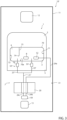
- the actuation circuit 51 comprises, in turn, a pump 52 adapted to suck oil from oil sump 3, a remote valve 20 fluidly connected to pump 52, implement 50 fluidly connected to remote valve 20 and a duct 7 fluidly connecting remote valve 20 to driveline assembly 1 ( Figure 1 ).
- duct 7 directly fluidly connects remote valve 20 to oil reservoir 4.
- Pump 52 is adapted to deliver the oil sucked from oil sump 3 to remote valve 20.
- actuation circuit 51 further comprises in succession a stretch 24a fluidly connecting pump 52 to remote valve 20, a stretch 24b fluidly connecting remote valve 20 to implement 50 and a stretch 24c fluidly connecting implement 50 to remote valve 20.
- actuation circuit 51 comprises deaeration means 53 adapted to remove oxygen and other dissolved gases from the oil flowing through it.
- actuation circuit 51 comprises a deaerator 54 at duct 7.
- drivelines assembly 1 comprises a pumping system 8, which is adapted to suck oil from oil sump 3 and to direct it to the mechanical components of driveline 2 to be lubricated.
- driveline assembly 1 and work vehicle 10 The operation of driveline assembly 1 and work vehicle 10 according to the present invention is described in the following.
- oil of driveline assembly 1 is contained in part in oil sump 3 and in part in oil reservoir 4.
- pump 52 sucks oil from oil sump 3 and delivers it to remote valve 20.
- Remote valve 20 delivers the sucked oil to implement 50.
- oil flows from pump 52 to remote valve 20 through stretch 24a and from remote valve 20 to implement 50 through stretch 24b.
- 10' denotes a work vehicle according to a second embodiment of the present invention.
- Work vehicle 10' is similar to work vehicle 10 and will be described hereinafter only insofar as it differs from the latter; equal or equivalent parts of work vehicles 10; 10' will be marked, where possible, by the same reference numerals.
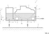
- Work vehicle 10' differs from work vehicle 10 in that duct 7 comprises a stretch 21' extending from remote valve 20, a stretch 22' directly fluidly connecting stretch 21' to oil sump 3 and a stretch 23' directly fluidly connecting stretch 21' to oil reservoir 4.
- stretches 21', 22' and 23' are jointed with one another by a T-connection or a three-way fitting.
- driveline assembly 1 comprises valve means adapted to control the flow of oil between stretch 21' and oil sump 3 and/or between stretch 21' and oil reservoir 4.
- the valve means are arranged at duct 7 and comprise a hydraulically actuated valve or an electro-hydraulically actuated valve.
- valve means are adapted to control the flow of oil such that the flow rate of oil flowing between stretch 21' and oil reservoir 4 is greater than the flow rate of oil flowing between stretch 21' and oil sump 3.
- valve means may be adapted to completely deny the fluidic communication between stretch 21' and oil sump 3 and allow the fluidic communication between stretch 21' and oil reservoir 4.
- actuation circuit 51 comprises deaeration means 53' adapted to remove oxygen and other dissolved gases from the oil flowing through it.
- actuation circuit 51 comprises a deaerator 55' at stretch 22' and/or a deaerator 54 at stretch 23'.
- driveline 2 transmits motion from motor means 13 to wheels 12 and the mechanical components of driveline 2 are lubricated by oil splashing and pumping system 8.
- the mechanical components of driveline 2 are partially immersed in the oil contained in oil sump 3 and lubricate the contact surfaces thereof by virtue of their movements.
- pumping system 8 sucks oil from oil sump 3 and sprays it towards the mechanical components of driveline 2.
- valve means control the flow of oil flowing between stretch 21' and oil sump 3 and/or between stretch 21' and oil reservoir 4.
- oil flows from oil reservoir 4 to oil sump 3 and vice versa through orifice 74.
- driveline assembly 1; 1' comprises oil reservoir 4, which is fluidly connected to oil sump 3, integral and adjacent to oil sump 3, the oil capacity of driveline assembly 1 is increased without causing an increase in power losses.
- duct 7 of driveline assembly 1 directly fluidly connects remote valve 20 to oil reservoir 4, the velocity of the flow coming from remote valve 20 and directed to oil sump 3 can be reduced. As a result, turbulence and aeration of the oil is limited. In particular, oil reservoir 4 allows the oil to stagnate and to be deareated. Deaeration is enhanced also by deaerator means 53.
- work vehicle 10; 10' might comprise tracks instead of wheels 12.
- Body 70 might comprise more than one septum 73 and each septum 73 might comprise more than one opening 74.
- Work vehicle 10; 10' might comprise more than one implement 50 and more than one actuation circuits 51.
Landscapes
- Engineering & Computer Science (AREA)
- General Engineering & Computer Science (AREA)
- Mechanical Engineering (AREA)
- General Details Of Gearings (AREA)
Abstract
Description
- The present invention concerns a driveline assembly for a work vehicle and a work vehicle comprising a driveline assembly.
- Work vehicles are known comprising a main body, a locomotion system including wheels or tracks for moving the main body with respect to the ground, a propulsion system including a thermal engine and/or an electric motor, and a driveline, which operatively connects the locomotion system to the propulsion system.
- In general, the drivelines comprise a plurality of mechanical components (e.g., gears and bearings), which are lubricated to reduce friction and wear between their contact surfaces. By way of example, the drivelines are lubricated by oil splashing, i.e., by splashing caused by the movement of the mechanical components.
- For this purpose, the work vehicle comprises an oil sump, which contains oil in which the mechanical components are partially immersed, and which is adapted to collect the oil that falls due to gravity after lubricating the mechanical components.
- However, the capacity of oil of the drivelines is limited by the fact that as the amount of oil increases, the power losses increase, as a consequence of the fact that the oil level in the oil sump rises and the portion of the mechanical components immersed in the oil increases.
- The work vehicles are known to further comprise at least one hydraulically operated implement and a relative hydraulic circuit for the actuation of the implement.
- In detail, the circuit comprises the oil sump, the hydraulically operated implement, a pump and a remote valve. The oil pump is adapted to suck oil from the oil sump and to deliver it to the remote valve. The oil flowing through the remote valve is then used to actuate the implement and is discharged into the oil sump. In other words, the oil contained in the oil sump is adapted both to lubricate the mechanical components of the driveline and to actuate the implement(s).
- However, the flow of oil arriving in the oil sump from the remote valve is characterized by high velocity and tends to cause turbulence of the oil contained therein, consequently affecting lubrication quality.
- The quality of lubrication is further reduced by aeration of the oil caused by splashing and high velocity of the flow coming from the remove valve.
- Therefore, there is a need within the industry for a driveline assembly for a work vehicle allowing the quality of lubrication of the mechanical components of the driveline to be improved.
- The aforementioned aim is reached by a driveline assembly for a work vehicle, as claimed in the appended independent claim.
- Preferred embodiments of the invention are realized according to the claims dependent or related to the above independent claim.
- For a better understanding of the present invention, two preferred embodiments are described in the following, by way of a non-limiting example, with reference to the attached drawing wherein:
-
Figure 1 is a schematic representation of a work vehicle comprising a driveline assembly according to a first embodiment of the present invention; and -
Figure 2 is a schematic representation of a portion of the driveline assembly ofFigure 1 ; -
Figure 3 is a schematic representation of a work vehicle comprising a driveline assembly according to a second embodiment of the present invention; and -
Figure 4 is a schematic representation of a portion of the driveline assembly ofFigure 3 . - With reference to
figure 1 , numeral 10 indicates a work vehicle, in particular an agricultural vehicle such as a tractor. -
Work vehicle 10 comprises amain body 11, a plurality ofwheels 12, which are rotatable relative tomain body 11 about respective rotational axes and motor means 13 (e.g., a thermal engine and/or an electric motor) adapted to rotatewheels 12 about their respective rotational axes. -
Work vehicle 10 further comprises adriveline assembly 1.Driveline assembly 1 comprises, in turn, adriveline 2 adapted to operatively connect motor means 13 towheels 12 and anoil sump 3 for collecting by gravity an oil adapted to lubricatedriveline 2. -
Driveline 2 comprises a plurality of mechanical components - which are known per se and not shown - adapted to transmit motion from motor means 13 towheels 12. By way of example,driveline 2 comprises a plurality of wheels and bearings. In further detail, at least some of the mechanical components are at least partially immersed in the oil contained in oil sump 3 (Figure 2 ). - Advantageously,
driveline assembly 1 comprises anoil reservoir 4 fluidly connected tooil sump 3; in addition,oil reservoir 4 andoil sump 3 are integral and adjacent to each other.Oil reservoir 4 is adapted to contain oil, specifically the same oil contained inoil sump 3. - As shown in
Figure 2 ,oil reservoir 4 is arranged in such a manner that the mechanical components ofdriveline 2 are spaced away from the oil volume contained inoil reservoir 4. In other words, the mechanical components ofdriveline 2 are not immersed in the oil contained inoil reservoir 4. - In addition, preferably,
oil reservoir 4 is spaced away from a projection of the mechanical components ofdriveline 2 onto a plane perpendicular to acceleration vector g. As a result, unlikeoil sump 3,oil reservoir 4 is not adapted to directly collect the oil falling by gravity from the mechanical components of driveline 2 (Figure 2 ). - In the preferred embodiment shown,
driveline assembly 1 comprises abody 70.Body 70 comprises, in turn, avolume 71, avolume 72 and aseptum 73 adapted to delimitvolume 71 fromvolume 72.Volume 71 comprises and/or definesoil sump 3 andvolume 72 comprises and/or definesoil reservoir 4. In other words,oil sump 3 andoil reservoir 4 are two compartments ofbody 70. - In detail,
septum 73 comprises anopening 74, which fluidly connectsvolume 71 withvolume 72. -
Body 70 comprises abasement wall 70a, which is transversal toseptum 73 and constitutes the portion ofbody 70 closest to the ground S on whichwheels 12 rest. In greater detail,septum 73 is spaced frombasement wall 70a along a vertical direction Z parallel to acceleration vector g andopening 74 is defined by the orifice betweenseptum 73 andbasement wall 70a along vertical direction Z (Figure 2 ). Alternatively, opening 74 is spaced frombasement wall 70a along vertical direction Z. -
Driveline assembly 1 also comprises acontainer 5 enclosing at least inpart driveline 2. In addition,container 5 comprisesbody 70 or is defined at least in part bybody 70. Preferably but not necessarily,body 70 constitutes the lowermost portion ofcontainer 5 according to vertical direction Z, i.e., the portion ofcontainer 5 closest to the ground S. -
Work vehicle 1 further comprises at least oneimplement 50, which is hydraulically operated and anactuation circuit 51 for the actuation ofimplement 50. By way of example,implement 50 is a front end loader. - The
actuation circuit 51 comprises, in turn, apump 52 adapted to suck oil fromoil sump 3, aremote valve 20 fluidly connected topump 52, implement 50 fluidly connected toremote valve 20 and aduct 7 fluidly connectingremote valve 20 to driveline assembly 1 (Figure 1 ). - In detail,
duct 7 directly fluidly connectsremote valve 20 tooil reservoir 4. -
Pump 52 is adapted to deliver the oil sucked fromoil sump 3 toremote valve 20. - As schematized in
Figure 1 ,actuation circuit 51 further comprises in succession astretch 24a fluidly connectingpump 52 toremote valve 20, astretch 24b fluidly connectingremote valve 20 to implement 50 and astretch 24c fluidly connecting implement 50 toremote valve 20. - Preferably,
actuation circuit 51 comprises deaeration means 53 adapted to remove oxygen and other dissolved gases from the oil flowing through it. In detail,actuation circuit 51 comprises adeaerator 54 atduct 7. - Preferably but not necessarily,
drivelines assembly 1 comprises apumping system 8, which is adapted to suck oil fromoil sump 3 and to direct it to the mechanical components ofdriveline 2 to be lubricated. - The operation of
driveline assembly 1 andwork vehicle 10 according to the present invention is described in the following. - In use, the oil of
driveline assembly 1 is contained in part inoil sump 3 and in part inoil reservoir 4. - During operation,
driveline 2 transmits motion from motor means 13 towheels 12 and the mechanical components ofdriveline 2 are lubricated by oil splashing andpumping system 8. In particular, at least some of the mechanical components ofdriveline 2 are partially immersed in the oil contained inoil sump 3 and lubricate the contact surfaces thereof by virtue of their movements. At the same time,pumping system 8 sucks oil fromoil sump 3 and sprays it towards the mechanical components ofdriveline 2. - At the same time, pump 52 sucks oil from
oil sump 3 and delivers it toremote valve 20.Remote valve 20, in turn, delivers the sucked oil to implement 50. In detail, oil flows frompump 52 toremote valve 20 throughstretch 24a and fromremote valve 20 to implement 50 throughstretch 24b. - After actuating implement 50, the oil flows back to
remote valve 20 throughstretch 24c and then towardsoil reservoir 4 throughduct 7. - During operation, oil flows from
oil reservoir 4 tooil sump 3 and vice versa throughorifice 74. - With reference to
Figures 3 and4 , 10' denotes a work vehicle according to a second embodiment of the present invention. Work vehicle 10' is similar to workvehicle 10 and will be described hereinafter only insofar as it differs from the latter; equal or equivalent parts ofwork vehicles 10; 10' will be marked, where possible, by the same reference numerals. - Work vehicle 10' differs from
work vehicle 10 in thatduct 7 comprises a stretch 21' extending fromremote valve 20, a stretch 22' directly fluidly connecting stretch 21' tooil sump 3 and a stretch 23' directly fluidly connecting stretch 21' tooil reservoir 4. - In detail, stretches 21', 22' and 23' are jointed with one another by a T-connection or a three-way fitting.
- According to a not-shown embodiment,
driveline assembly 1 comprises valve means adapted to control the flow of oil between stretch 21' andoil sump 3 and/or between stretch 21' andoil reservoir 4. In particular, the valve means are arranged atduct 7 and comprise a hydraulically actuated valve or an electro-hydraulically actuated valve. - In detail, the valve means are adapted to control the flow of oil such that the flow rate of oil flowing between stretch 21' and
oil reservoir 4 is greater than the flow rate of oil flowing between stretch 21' andoil sump 3. In further detail, the valve means may be adapted to completely deny the fluidic communication between stretch 21' andoil sump 3 and allow the fluidic communication between stretch 21' andoil reservoir 4. - Preferably,
actuation circuit 51 comprises deaeration means 53' adapted to remove oxygen and other dissolved gases from the oil flowing through it. In detail,actuation circuit 51 comprises a deaerator 55' at stretch 22' and/or adeaerator 54 at stretch 23'. - The operation of driveline assembly 1' and work vehicle 10' according to the present invention is described in the following.
- In use, the oil of driveline assembly 1' is contained in part in
oil sump 3 and in part inoil reservoir 4. - During operation,
driveline 2 transmits motion from motor means 13 towheels 12 and the mechanical components ofdriveline 2 are lubricated by oil splashing andpumping system 8. In particular, at least some of the mechanical components ofdriveline 2 are partially immersed in the oil contained inoil sump 3 and lubricate the contact surfaces thereof by virtue of their movements. At the same time,pumping system 8 sucks oil fromoil sump 3 and sprays it towards the mechanical components ofdriveline 2. - At the same time, pump 52 sucks oil from
oil sump 3 and delivers it toremote valve 20.Remote valve 20, in turn, delivers the sucked oil towards implement 50. After actuating implement 50, the oil flows towardsoil sump 3 through stretch 22' andoil reservoir 4 through stretch 23'. - In the not-shown embodiment comprising the valve means, valve means control the flow of oil flowing between stretch 21' and
oil sump 3 and/or between stretch 21' andoil reservoir 4. - During operation, oil flows from
oil reservoir 4 tooil sump 3 and vice versa throughorifice 74. - In view of the foregoing, the advantages of
driveline assembly 1; 1' andwork vehicle 10; 10' according to the invention are apparent. - In particular, since
driveline assembly 1; 1' comprisesoil reservoir 4, which is fluidly connected tooil sump 3, integral and adjacent tooil sump 3, the oil capacity ofdriveline assembly 1 is increased without causing an increase in power losses. - Since
duct 7 ofdriveline assembly 1 directly fluidly connectsremote valve 20 tooil reservoir 4, the velocity of the flow coming fromremote valve 20 and directed tooil sump 3 can be reduced. As a result, turbulence and aeration of the oil is limited. In particular,oil reservoir 4 allows the oil to stagnate and to be deareated. Deaeration is enhanced also by deaerator means 53. - For the same reason as above, the suction capability of pumping
system 8 is increased. - It is clear that modifications can be made to
driveline assembly 1; 1' andwork vehicle 10; 10' which do not extend beyond the scope of protection defined by the claims. - In particular,
work vehicle 10; 10' might comprise tracks instead ofwheels 12. -
Body 70 might comprise more than oneseptum 73 and eachseptum 73 might comprise more than oneopening 74. -
Work vehicle 10; 10' might comprise more than one implement 50 and more than oneactuation circuits 51.
Claims (15)
- - Driveline assembly (1; 1') for a work vehicle (10; 10'), comprising:- a driveline (2) comprising a plurality of mechanical components adapted to operatively connect, in use, motor means (13) of said work vehicle (10; 10') to locomotion means (12) of said work vehicle (10; 10');- an oil sump (3) adapted to collect an oil lubricating, in use, said driveline (2);- an oil reservoir (4) adapted to contain said oil;wherein said oil reservoir (4) and said oil sump (3) are integral and adjacent to each other, and fluidly connected to each other.
- - Driveline assembly according to claim 1, wherein said mechanical components of said driveline (2) are spaced away from the oil contained, in use, in said oil reservoir (4).
- - Driveline assembly according to claim 1 or 2, wherein said oil reservoir (4) is spaced away from a projection of said mechanical components of said driveline (2) onto a plane perpendicular to acceleration vector (g).
- - Driveline assembly according to any one of the foregoing claims, further comprising a body (70);said body (70) comprises, in turn:- a first volume (71);- a second volume (72); and- at least one septum (73) adapted to delimit said first volume (71) from said second volume (72);wherein said first volume (71) comprises and/or defines said oil sump (3) and said second volume (72) comprises and/or defines said oil reservoir (4).
- - Driveline assembly according to claim 4, further comprising a container (5), which encloses at least in part said driveline (2) and said body (70) or being defined at least in part by said body (70).
- - Driveline assembly according to any one of the foregoing claims, comprising a pumping system (8) adapted to suck said oil from said oil sump (3) and to direct it, in use, to said driveline (2) to lubricate it.
- - Work vehicle (10; 10') comprising:- a main body (11);- locomotion means (12) adapted to move said main body (11) with respect to a reference system;- motor means (13) adapted to drive said locomotion means (12); and- a driveline assembly (1; 1') according to any one of the foregoing claims.
- - Work vehicle according to claim 7, comprising:- at least one implement (50), which is hydraulically operable;- an actuation circuit (51) for the actuation of said implement (50);said actuation circuit (51) comprising:- a pump (52) adapted to suck said oil from said oil sump (3) ;- a remote valve (20) fluidly connected to said pump (52) and said implement (50);- a duct (7; 7') fluidly connecting said remote valve (20) to said driveline assembly (1);said pump (52) being adapted to deliver, in use, said oil sucked from said oil sump (3) to said remote valve (20).
- - Work vehicle according to claim 8, wherein said duct (7) directly fluidly connects said remote valve (20) to said oil reservoir (4).
- - Work vehicle according to claim 8, wherein said duct (7') comprises:- a first stretch (21') extending from said remote valve (20) ;- a second stretch (23') directly fluidly connecting said first stretch (21') to said oil reservoir (4); and- a third stretch (22') directly fluidly connecting said first stretch (21') to said oil sump (3).
- - Work vehicle according to claim 10, comprising valve means adapted to control the flow of oil between said first stretch (21') and said oil sump (3) and/or between said first stretch (21') and said oil reservoir (4).
- - Work vehicle according to claim 11, wherein said valve means are adapted to control the flow of oil such that the flow rate of said oil flowing, in use, between said first stretch (21') and said oil reservoir (4) is greater than the flow rate of said oil flowing, in use, between said first stretch (21') and said oil sump (3).
- - Work vehicle according to claim 11 or 12, wherein said valve means comprise a hydraulically actuated valve or an electro-hydraulically actuated valve.
- - Work vehicle according to claim 9, wherein said actuation circuit (51) comprises deaeration means (53);
said deaeration means (53) comprising a deaerator (54) at said duct (7). - - Work vehicle according to any one of claims 10 to 13, wherein said actuation circuit (51) comprises deaeration means (53'); said deaeration means (53') comprising a deaerator (54) at said second stretch (22') and a deaerator (55) at said third stretch (23').
Applications Claiming Priority (1)
| Application Number | Priority Date | Filing Date | Title |
|---|---|---|---|
| IT102023000005019A IT202300005019A1 (en) | 2023-03-16 | 2023-03-16 | TRANSMISSION ASSEMBLY FOR A WORK VEHICLE AND WORK VEHICLE COMPRISING THE SAME |
Publications (2)
| Publication Number | Publication Date |
|---|---|
| EP4431763A1 true EP4431763A1 (en) | 2024-09-18 |
| EP4431763B1 EP4431763B1 (en) | 2026-02-18 |
Family
ID=86332375
Family Applications (1)
| Application Number | Title | Priority Date | Filing Date |
|---|---|---|---|
| EP24164303.0A Active EP4431763B1 (en) | 2023-03-16 | 2024-03-18 | Driveline assembly for a work vehicle and work vehicle comprising the same |
Country Status (2)
| Country | Link |
|---|---|
| EP (1) | EP4431763B1 (en) |
| IT (1) | IT202300005019A1 (en) |
Citations (5)
| Publication number | Priority date | Publication date | Assignee | Title |
|---|---|---|---|---|
| US3800913A (en) * | 1972-08-04 | 1974-04-02 | Caterpillar Tractor Co | Recirculating oil system |
| EP0479081A1 (en) * | 1990-09-25 | 1992-04-08 | Deere & Company | Pressure supply system for a vehicle transmission |
| US20020053489A1 (en) * | 2000-10-17 | 2002-05-09 | Detlev Schnitzer | Transmission for an internal combustion engine |
| JP2003166630A (en) * | 2001-11-29 | 2003-06-13 | Toyota Motor Corp | Lubrication device for starting frictional engagement device |
| DE102018211360A1 (en) * | 2018-07-10 | 2020-01-16 | Audi Ag | Lubricant supply system for a drive device of an electrically operated vehicle |
-
2023
- 2023-03-16 IT IT102023000005019A patent/IT202300005019A1/en unknown
-
2024
- 2024-03-18 EP EP24164303.0A patent/EP4431763B1/en active Active
Patent Citations (5)
| Publication number | Priority date | Publication date | Assignee | Title |
|---|---|---|---|---|
| US3800913A (en) * | 1972-08-04 | 1974-04-02 | Caterpillar Tractor Co | Recirculating oil system |
| EP0479081A1 (en) * | 1990-09-25 | 1992-04-08 | Deere & Company | Pressure supply system for a vehicle transmission |
| US20020053489A1 (en) * | 2000-10-17 | 2002-05-09 | Detlev Schnitzer | Transmission for an internal combustion engine |
| JP2003166630A (en) * | 2001-11-29 | 2003-06-13 | Toyota Motor Corp | Lubrication device for starting frictional engagement device |
| DE102018211360A1 (en) * | 2018-07-10 | 2020-01-16 | Audi Ag | Lubricant supply system for a drive device of an electrically operated vehicle |
Also Published As
| Publication number | Publication date |
|---|---|
| EP4431763B1 (en) | 2026-02-18 |
| IT202300005019A1 (en) | 2024-09-16 |
Similar Documents
| Publication | Publication Date | Title |
|---|---|---|
| CN204716945U (en) | There is the drive motor of motor and transmitting assemblies | |
| JP7071419B2 (en) | Cooling lubrication system with drywall | |
| EP2278191B1 (en) | Gear transmission system having a lubrication pump and a lubrication reservoir | |
| EP3730816B1 (en) | Low profile auxiliary lubrication system | |
| US6718847B2 (en) | Pressure-release device for a transmission housing | |
| US6779421B2 (en) | Hydrostatic transmission with internal fluid expansion chamber | |
| CN104968975B (en) | drive unit for vehicle | |
| CN110985645B (en) | Drive assembly with passive pump lubrication | |
| US8528594B2 (en) | Hydraulic system with leakage fluid removal | |
| CN102317596A (en) | Turbo compound system for a drive apparatus | |
| EP4431764B1 (en) | Work vehicle | |
| EP4431763B1 (en) | Driveline assembly for a work vehicle and work vehicle comprising the same | |
| EP4431762B1 (en) | Work vehicle | |
| US20250180108A1 (en) | Electric traction drive having an active and a passive coolant/lubricant circuit, and method for operating the traction drive | |
| JPH10252868A (en) | Air breather device | |
| JP4443131B2 (en) | Transmission housing piping structure | |
| JPS6313963A (en) | Oil circulating device in working vehicle | |
| KR102336579B1 (en) | Transmission Oil pan for work vehicle and Work vehicle containing the same | |
| EP4563846A1 (en) | Lubrication system of a propulsion system of an agricultural tractor | |
| JPH10272941A (en) | Hydrostatic transmission for vehicle running | |
| US12454952B2 (en) | Hydraulic pump arrangement | |
| JP4965342B2 (en) | Oil recovery structure for automatic transmission | |
| JP5867014B2 (en) | Foreign matter recovery structure for outboard motor lubricant | |
| JPH07158730A (en) | HST hydraulic motor idling prevention device and idling prevention method | |
| CN121007207A (en) | Drive assembly with exhaust device |
Legal Events
| Date | Code | Title | Description |
|---|---|---|---|
| PUAI | Public reference made under article 153(3) epc to a published international application that has entered the european phase |
Free format text: ORIGINAL CODE: 0009012 |
|
| STAA | Information on the status of an ep patent application or granted ep patent |
Free format text: STATUS: THE APPLICATION HAS BEEN PUBLISHED |
|
| AK | Designated contracting states |
Kind code of ref document: A1 Designated state(s): AL AT BE BG CH CY CZ DE DK EE ES FI FR GB GR HR HU IE IS IT LI LT LU LV MC ME MK MT NL NO PL PT RO RS SE SI SK SM TR |
|
| STAA | Information on the status of an ep patent application or granted ep patent |
Free format text: STATUS: REQUEST FOR EXAMINATION WAS MADE |
|
| 17P | Request for examination filed |
Effective date: 20250318 |
|
| GRAP | Despatch of communication of intention to grant a patent |
Free format text: ORIGINAL CODE: EPIDOSNIGR1 |
|
| STAA | Information on the status of an ep patent application or granted ep patent |
Free format text: STATUS: GRANT OF PATENT IS INTENDED |
|
| RIC1 | Information provided on ipc code assigned before grant |
Ipc: F16H 57/027 20120101AFI20250812BHEP Ipc: F16H 57/04 20100101ALI20250812BHEP |
|
| INTG | Intention to grant announced |
Effective date: 20250911 |
|
| GRAS | Grant fee paid |
Free format text: ORIGINAL CODE: EPIDOSNIGR3 |
|
| GRAA | (expected) grant |
Free format text: ORIGINAL CODE: 0009210 |
|
| STAA | Information on the status of an ep patent application or granted ep patent |
Free format text: STATUS: THE PATENT HAS BEEN GRANTED |
|
| AK | Designated contracting states |
Kind code of ref document: B1 Designated state(s): AL AT BE BG CH CY CZ DE DK EE ES FI FR GB GR HR HU IE IS IT LI LT LU LV MC ME MK MT NL NO PL PT RO RS SE SI SK SM TR |
|
| REG | Reference to a national code |
Ref country code: CH Ref legal event code: F10 Free format text: ST27 STATUS EVENT CODE: U-0-0-F10-F00 (AS PROVIDED BY THE NATIONAL OFFICE) Effective date: 20260218 Ref country code: GB Ref legal event code: FG4D |
|
| REG | Reference to a national code |
Ref country code: IE Ref legal event code: FG4D |
|
| REG | Reference to a national code |
Ref country code: DE Ref legal event code: R096 Ref document number: 602024002561 Country of ref document: DE |
|
| PGFP | Annual fee paid to national office [announced via postgrant information from national office to epo] |
Ref country code: DE Payment date: 20260320 Year of fee payment: 3 |
|
| PGFP | Annual fee paid to national office [announced via postgrant information from national office to epo] |
Ref country code: AT Payment date: 20260301 Year of fee payment: 3 |
|
| PGFP | Annual fee paid to national office [announced via postgrant information from national office to epo] |
Ref country code: FR Payment date: 20260323 Year of fee payment: 3 |
|
| REG | Reference to a national code |
Ref country code: NL Ref legal event code: MP Effective date: 20260218 |
|
| PG25 | Lapsed in a contracting state [announced via postgrant information from national office to epo] |
Ref country code: RS Free format text: LAPSE BECAUSE OF FAILURE TO SUBMIT A TRANSLATION OF THE DESCRIPTION OR TO PAY THE FEE WITHIN THE PRESCRIBED TIME-LIMIT Effective date: 20260518 |
|
| PG25 | Lapsed in a contracting state [announced via postgrant information from national office to epo] |
Ref country code: ES Free format text: LAPSE BECAUSE OF FAILURE TO SUBMIT A TRANSLATION OF THE DESCRIPTION OR TO PAY THE FEE WITHIN THE PRESCRIBED TIME-LIMIT Effective date: 20260218 |
|
| PG25 | Lapsed in a contracting state [announced via postgrant information from national office to epo] |
Ref country code: PL Free format text: LAPSE BECAUSE OF FAILURE TO SUBMIT A TRANSLATION OF THE DESCRIPTION OR TO PAY THE FEE WITHIN THE PRESCRIBED TIME-LIMIT Effective date: 20260218 |
|
| PG25 | Lapsed in a contracting state [announced via postgrant information from national office to epo] |
Ref country code: GR Free format text: LAPSE BECAUSE OF FAILURE TO SUBMIT A TRANSLATION OF THE DESCRIPTION OR TO PAY THE FEE WITHIN THE PRESCRIBED TIME-LIMIT Effective date: 20260519 |
|
| PGFP | Annual fee paid to national office [announced via postgrant information from national office to epo] |
Ref country code: IT Payment date: 20260331 Year of fee payment: 3 |
|
| REG | Reference to a national code |
Ref country code: LT Ref legal event code: MG9D |
|
| PG25 | Lapsed in a contracting state [announced via postgrant information from national office to epo] |
Ref country code: LT Free format text: LAPSE BECAUSE OF FAILURE TO SUBMIT A TRANSLATION OF THE DESCRIPTION OR TO PAY THE FEE WITHIN THE PRESCRIBED TIME-LIMIT Effective date: 20260218 |
|
| PG25 | Lapsed in a contracting state [announced via postgrant information from national office to epo] |
Ref country code: NO Free format text: LAPSE BECAUSE OF FAILURE TO SUBMIT A TRANSLATION OF THE DESCRIPTION OR TO PAY THE FEE WITHIN THE PRESCRIBED TIME-LIMIT Effective date: 20260518 |
|
| PG25 | Lapsed in a contracting state [announced via postgrant information from national office to epo] |
Ref country code: FI Free format text: LAPSE BECAUSE OF FAILURE TO SUBMIT A TRANSLATION OF THE DESCRIPTION OR TO PAY THE FEE WITHIN THE PRESCRIBED TIME-LIMIT Effective date: 20260218 Ref country code: AT Free format text: LAPSE BECAUSE OF FAILURE TO SUBMIT A TRANSLATION OF THE DESCRIPTION OR TO PAY THE FEE WITHIN THE PRESCRIBED TIME-LIMIT Effective date: 20260218 Ref country code: SE Free format text: LAPSE BECAUSE OF FAILURE TO SUBMIT A TRANSLATION OF THE DESCRIPTION OR TO PAY THE FEE WITHIN THE PRESCRIBED TIME-LIMIT Effective date: 20260218 |
|
| REG | Reference to a national code |
Ref country code: AT Ref legal event code: MK05 Ref document number: 1888330 Country of ref document: AT Kind code of ref document: T Effective date: 20260218 |
|
| PG25 | Lapsed in a contracting state [announced via postgrant information from national office to epo] |
Ref country code: HR Free format text: LAPSE BECAUSE OF FAILURE TO SUBMIT A TRANSLATION OF THE DESCRIPTION OR TO PAY THE FEE WITHIN THE PRESCRIBED TIME-LIMIT Effective date: 20260218 |
|
| PG25 | Lapsed in a contracting state [announced via postgrant information from national office to epo] |
Ref country code: PT Free format text: LAPSE BECAUSE OF FAILURE TO SUBMIT A TRANSLATION OF THE DESCRIPTION OR TO PAY THE FEE WITHIN THE PRESCRIBED TIME-LIMIT Effective date: 20260618 Ref country code: IS Free format text: LAPSE BECAUSE OF FAILURE TO SUBMIT A TRANSLATION OF THE DESCRIPTION OR TO PAY THE FEE WITHIN THE PRESCRIBED TIME-LIMIT Effective date: 20260618 |
|
| PG25 | Lapsed in a contracting state [announced via postgrant information from national office to epo] |
Ref country code: NL Free format text: LAPSE BECAUSE OF FAILURE TO SUBMIT A TRANSLATION OF THE DESCRIPTION OR TO PAY THE FEE WITHIN THE PRESCRIBED TIME-LIMIT Effective date: 20260218 |
|
| PG25 | Lapsed in a contracting state [announced via postgrant information from national office to epo] |
Ref country code: LV Free format text: LAPSE BECAUSE OF FAILURE TO SUBMIT A TRANSLATION OF THE DESCRIPTION OR TO PAY THE FEE WITHIN THE PRESCRIBED TIME-LIMIT Effective date: 20260218 |
|
| PG25 | Lapsed in a contracting state [announced via postgrant information from national office to epo] |
Ref country code: BG Free format text: LAPSE BECAUSE OF FAILURE TO SUBMIT A TRANSLATION OF THE DESCRIPTION OR TO PAY THE FEE WITHIN THE PRESCRIBED TIME-LIMIT Effective date: 20260218 |