EP4431590A1 - Intelligent gene synthesis and monoclonal selection system - Google Patents
Intelligent gene synthesis and monoclonal selection system Download PDFInfo
- Publication number
- EP4431590A1 EP4431590A1 EP22892104.5A EP22892104A EP4431590A1 EP 4431590 A1 EP4431590 A1 EP 4431590A1 EP 22892104 A EP22892104 A EP 22892104A EP 4431590 A1 EP4431590 A1 EP 4431590A1
- Authority
- EP
- European Patent Office
- Prior art keywords
- compartment
- unit
- monoclonal
- gene synthesis
- pick head
- Prior art date
- Legal status (The legal status is an assumption and is not a legal conclusion. Google has not performed a legal analysis and makes no representation as to the accuracy of the status listed.)
- Pending
Links
- 108090000623 proteins and genes Proteins 0.000 title claims abstract description 101
- 230000015572 biosynthetic process Effects 0.000 title claims abstract description 91
- 238000003786 synthesis reaction Methods 0.000 title claims abstract description 91
- 239000007788 liquid Substances 0.000 claims abstract description 109
- 238000000746 purification Methods 0.000 claims abstract description 64
- 238000000034 method Methods 0.000 claims abstract description 63
- 230000008569 process Effects 0.000 claims abstract description 61
- 230000003321 amplification Effects 0.000 claims abstract description 37
- 238000003199 nucleic acid amplification method Methods 0.000 claims abstract description 37
- 238000002156 mixing Methods 0.000 claims abstract description 32
- 108020004707 nucleic acids Proteins 0.000 claims abstract description 30
- 150000007523 nucleic acids Chemical class 0.000 claims abstract description 30
- 102000039446 nucleic acids Human genes 0.000 claims abstract description 30
- 239000003153 chemical reaction reagent Substances 0.000 claims abstract description 22
- 239000012634 fragment Substances 0.000 claims abstract description 20
- 239000012472 biological sample Substances 0.000 claims abstract description 12
- 238000011403 purification operation Methods 0.000 claims abstract description 10
- 239000013598 vector Substances 0.000 claims abstract description 8
- 238000012258 culturing Methods 0.000 claims abstract description 6
- 230000003407 synthetizing effect Effects 0.000 claims abstract description 6
- 238000012937 correction Methods 0.000 claims abstract description 5
- 238000012546 transfer Methods 0.000 claims description 55
- 238000004140 cleaning Methods 0.000 claims description 42
- 230000007246 mechanism Effects 0.000 claims description 42
- 238000003860 storage Methods 0.000 claims description 39
- 238000000576 coating method Methods 0.000 claims description 34
- 238000011068 loading method Methods 0.000 claims description 33
- 239000011248 coating agent Substances 0.000 claims description 32
- 239000000463 material Substances 0.000 claims description 29
- 238000007667 floating Methods 0.000 claims description 26
- 238000001035 drying Methods 0.000 claims description 22
- 238000005086 pumping Methods 0.000 claims description 17
- 238000001914 filtration Methods 0.000 claims description 16
- 230000003287 optical effect Effects 0.000 claims description 11
- 238000010438 heat treatment Methods 0.000 claims description 10
- 230000010355 oscillation Effects 0.000 claims description 10
- 238000012544 monitoring process Methods 0.000 claims description 7
- 230000002441 reversible effect Effects 0.000 claims description 6
- 238000013500 data storage Methods 0.000 claims description 5
- 238000012216 screening Methods 0.000 claims description 5
- 238000001816 cooling Methods 0.000 claims description 4
- 238000009827 uniform distribution Methods 0.000 claims description 4
- 230000004807 localization Effects 0.000 claims description 3
- 229910001220 stainless steel Inorganic materials 0.000 claims description 3
- 239000010935 stainless steel Substances 0.000 claims description 3
- 239000012620 biological material Substances 0.000 claims description 2
- 241000894006 Bacteria Species 0.000 description 27
- 238000006243 chemical reaction Methods 0.000 description 19
- 239000000523 sample Substances 0.000 description 17
- 239000012530 fluid Substances 0.000 description 14
- 239000007789 gas Substances 0.000 description 14
- 229920001817 Agar Polymers 0.000 description 11
- 239000008272 agar Substances 0.000 description 11
- 230000001580 bacterial effect Effects 0.000 description 10
- 239000000243 solution Substances 0.000 description 10
- 238000004519 manufacturing process Methods 0.000 description 8
- 239000003814 drug Substances 0.000 description 7
- 229940079593 drug Drugs 0.000 description 7
- 238000000605 extraction Methods 0.000 description 7
- 239000013612 plasmid Substances 0.000 description 7
- 239000011324 bead Substances 0.000 description 6
- 238000004458 analytical method Methods 0.000 description 5
- 238000012545 processing Methods 0.000 description 5
- 239000002699 waste material Substances 0.000 description 5
- 238000011161 development Methods 0.000 description 4
- 239000000428 dust Substances 0.000 description 4
- 239000004519 grease Substances 0.000 description 4
- 238000011160 research Methods 0.000 description 4
- 238000011109 contamination Methods 0.000 description 3
- 238000012864 cross contamination Methods 0.000 description 3
- 238000013461 design Methods 0.000 description 3
- 238000005516 engineering process Methods 0.000 description 3
- 230000010354 integration Effects 0.000 description 3
- 238000012986 modification Methods 0.000 description 3
- 230000004048 modification Effects 0.000 description 3
- 238000012163 sequencing technique Methods 0.000 description 3
- LFQSCWFLJHTTHZ-UHFFFAOYSA-N Ethanol Chemical compound CCO LFQSCWFLJHTTHZ-UHFFFAOYSA-N 0.000 description 2
- 238000012408 PCR amplification Methods 0.000 description 2
- 238000007664 blowing Methods 0.000 description 2
- 239000007853 buffer solution Substances 0.000 description 2
- 239000000356 contaminant Substances 0.000 description 2
- 238000001514 detection method Methods 0.000 description 2
- 230000000694 effects Effects 0.000 description 2
- 238000005485 electric heating Methods 0.000 description 2
- 230000003203 everyday effect Effects 0.000 description 2
- 239000001963 growth medium Substances 0.000 description 2
- 238000011065 in-situ storage Methods 0.000 description 2
- 239000011344 liquid material Substances 0.000 description 2
- 238000005461 lubrication Methods 0.000 description 2
- 230000009467 reduction Effects 0.000 description 2
- 238000012827 research and development Methods 0.000 description 2
- 238000007789 sealing Methods 0.000 description 2
- 239000007787 solid Substances 0.000 description 2
- 230000001954 sterilising effect Effects 0.000 description 2
- 230000009466 transformation Effects 0.000 description 2
- 238000011144 upstream manufacturing Methods 0.000 description 2
- 238000002965 ELISA Methods 0.000 description 1
- 230000009471 action Effects 0.000 description 1
- 230000000712 assembly Effects 0.000 description 1
- 238000000429 assembly Methods 0.000 description 1
- 238000004364 calculation method Methods 0.000 description 1
- 230000003749 cleanliness Effects 0.000 description 1
- 238000004891 communication Methods 0.000 description 1
- 238000010924 continuous production Methods 0.000 description 1
- 230000001351 cycling effect Effects 0.000 description 1
- 238000013480 data collection Methods 0.000 description 1
- 238000013523 data management Methods 0.000 description 1
- 238000011156 evaluation Methods 0.000 description 1
- 238000013537 high throughput screening Methods 0.000 description 1
- 238000012165 high-throughput sequencing Methods 0.000 description 1
- 239000012535 impurity Substances 0.000 description 1
- 230000003993 interaction Effects 0.000 description 1
- 238000011031 large-scale manufacturing process Methods 0.000 description 1
- 238000004989 laser desorption mass spectroscopy Methods 0.000 description 1
- 230000007774 longterm Effects 0.000 description 1
- 238000003754 machining Methods 0.000 description 1
- 238000005065 mining Methods 0.000 description 1
- 238000003032 molecular docking Methods 0.000 description 1
- 239000002547 new drug Substances 0.000 description 1
- 238000007481 next generation sequencing Methods 0.000 description 1
- 238000005457 optimization Methods 0.000 description 1
- 239000002245 particle Substances 0.000 description 1
- 230000002572 peristaltic effect Effects 0.000 description 1
- 238000011112 process operation Methods 0.000 description 1
- 238000004659 sterilization and disinfection Methods 0.000 description 1
- 238000012384 transportation and delivery Methods 0.000 description 1
- -1 various consumables Substances 0.000 description 1
Images










Classifications
-
- C—CHEMISTRY; METALLURGY
- C12—BIOCHEMISTRY; BEER; SPIRITS; WINE; VINEGAR; MICROBIOLOGY; ENZYMOLOGY; MUTATION OR GENETIC ENGINEERING
- C12M—APPARATUS FOR ENZYMOLOGY OR MICROBIOLOGY; APPARATUS FOR CULTURING MICROORGANISMS FOR PRODUCING BIOMASS, FOR GROWING CELLS OR FOR OBTAINING FERMENTATION OR METABOLIC PRODUCTS, i.e. BIOREACTORS OR FERMENTERS
- C12M41/00—Means for regulation, monitoring, measurement or control, e.g. flow regulation
- C12M41/48—Automatic or computerized control
-
- C—CHEMISTRY; METALLURGY
- C12—BIOCHEMISTRY; BEER; SPIRITS; WINE; VINEGAR; MICROBIOLOGY; ENZYMOLOGY; MUTATION OR GENETIC ENGINEERING
- C12M—APPARATUS FOR ENZYMOLOGY OR MICROBIOLOGY; APPARATUS FOR CULTURING MICROORGANISMS FOR PRODUCING BIOMASS, FOR GROWING CELLS OR FOR OBTAINING FERMENTATION OR METABOLIC PRODUCTS, i.e. BIOREACTORS OR FERMENTERS
- C12M23/00—Constructional details, e.g. recesses, hinges
- C12M23/02—Form or structure of the vessel
- C12M23/12—Well or multiwell plates
-
- C—CHEMISTRY; METALLURGY
- C12—BIOCHEMISTRY; BEER; SPIRITS; WINE; VINEGAR; MICROBIOLOGY; ENZYMOLOGY; MUTATION OR GENETIC ENGINEERING
- C12M—APPARATUS FOR ENZYMOLOGY OR MICROBIOLOGY; APPARATUS FOR CULTURING MICROORGANISMS FOR PRODUCING BIOMASS, FOR GROWING CELLS OR FOR OBTAINING FERMENTATION OR METABOLIC PRODUCTS, i.e. BIOREACTORS OR FERMENTERS
- C12M25/00—Means for supporting, enclosing or fixing the microorganisms, e.g. immunocoatings
- C12M25/02—Membranes; Filters
- C12M25/04—Membranes; Filters in combination with well or multiwell plates, i.e. culture inserts
-
- C—CHEMISTRY; METALLURGY
- C12—BIOCHEMISTRY; BEER; SPIRITS; WINE; VINEGAR; MICROBIOLOGY; ENZYMOLOGY; MUTATION OR GENETIC ENGINEERING
- C12M—APPARATUS FOR ENZYMOLOGY OR MICROBIOLOGY; APPARATUS FOR CULTURING MICROORGANISMS FOR PRODUCING BIOMASS, FOR GROWING CELLS OR FOR OBTAINING FERMENTATION OR METABOLIC PRODUCTS, i.e. BIOREACTORS OR FERMENTERS
- C12M29/00—Means for introduction, extraction or recirculation of materials, e.g. pumps
- C12M29/06—Nozzles; Sprayers; Spargers; Diffusers
-
- C—CHEMISTRY; METALLURGY
- C12—BIOCHEMISTRY; BEER; SPIRITS; WINE; VINEGAR; MICROBIOLOGY; ENZYMOLOGY; MUTATION OR GENETIC ENGINEERING
- C12M—APPARATUS FOR ENZYMOLOGY OR MICROBIOLOGY; APPARATUS FOR CULTURING MICROORGANISMS FOR PRODUCING BIOMASS, FOR GROWING CELLS OR FOR OBTAINING FERMENTATION OR METABOLIC PRODUCTS, i.e. BIOREACTORS OR FERMENTERS
- C12M33/00—Means for introduction, transport, positioning, extraction, harvesting, peeling or sampling of biological material in or from the apparatus
- C12M33/04—Means for introduction, transport, positioning, extraction, harvesting, peeling or sampling of biological material in or from the apparatus by injection or suction, e.g. using pipettes, syringes, needles
-
- C—CHEMISTRY; METALLURGY
- C12—BIOCHEMISTRY; BEER; SPIRITS; WINE; VINEGAR; MICROBIOLOGY; ENZYMOLOGY; MUTATION OR GENETIC ENGINEERING
- C12M—APPARATUS FOR ENZYMOLOGY OR MICROBIOLOGY; APPARATUS FOR CULTURING MICROORGANISMS FOR PRODUCING BIOMASS, FOR GROWING CELLS OR FOR OBTAINING FERMENTATION OR METABOLIC PRODUCTS, i.e. BIOREACTORS OR FERMENTERS
- C12M33/00—Means for introduction, transport, positioning, extraction, harvesting, peeling or sampling of biological material in or from the apparatus
- C12M33/08—Means for introduction, transport, positioning, extraction, harvesting, peeling or sampling of biological material in or from the apparatus by vibration
-
- C—CHEMISTRY; METALLURGY
- C12—BIOCHEMISTRY; BEER; SPIRITS; WINE; VINEGAR; MICROBIOLOGY; ENZYMOLOGY; MUTATION OR GENETIC ENGINEERING
- C12M—APPARATUS FOR ENZYMOLOGY OR MICROBIOLOGY; APPARATUS FOR CULTURING MICROORGANISMS FOR PRODUCING BIOMASS, FOR GROWING CELLS OR FOR OBTAINING FERMENTATION OR METABOLIC PRODUCTS, i.e. BIOREACTORS OR FERMENTERS
- C12M41/00—Means for regulation, monitoring, measurement or control, e.g. flow regulation
-
- C—CHEMISTRY; METALLURGY
- C12—BIOCHEMISTRY; BEER; SPIRITS; WINE; VINEGAR; MICROBIOLOGY; ENZYMOLOGY; MUTATION OR GENETIC ENGINEERING
- C12M—APPARATUS FOR ENZYMOLOGY OR MICROBIOLOGY; APPARATUS FOR CULTURING MICROORGANISMS FOR PRODUCING BIOMASS, FOR GROWING CELLS OR FOR OBTAINING FERMENTATION OR METABOLIC PRODUCTS, i.e. BIOREACTORS OR FERMENTERS
- C12M41/00—Means for regulation, monitoring, measurement or control, e.g. flow regulation
- C12M41/12—Means for regulation, monitoring, measurement or control, e.g. flow regulation of temperature
-
- C—CHEMISTRY; METALLURGY
- C12—BIOCHEMISTRY; BEER; SPIRITS; WINE; VINEGAR; MICROBIOLOGY; ENZYMOLOGY; MUTATION OR GENETIC ENGINEERING
- C12M—APPARATUS FOR ENZYMOLOGY OR MICROBIOLOGY; APPARATUS FOR CULTURING MICROORGANISMS FOR PRODUCING BIOMASS, FOR GROWING CELLS OR FOR OBTAINING FERMENTATION OR METABOLIC PRODUCTS, i.e. BIOREACTORS OR FERMENTERS
- C12M41/00—Means for regulation, monitoring, measurement or control, e.g. flow regulation
- C12M41/46—Means for regulation, monitoring, measurement or control, e.g. flow regulation of cellular or enzymatic activity or functionality, e.g. cell viability
-
- C—CHEMISTRY; METALLURGY
- C12—BIOCHEMISTRY; BEER; SPIRITS; WINE; VINEGAR; MICROBIOLOGY; ENZYMOLOGY; MUTATION OR GENETIC ENGINEERING
- C12M—APPARATUS FOR ENZYMOLOGY OR MICROBIOLOGY; APPARATUS FOR CULTURING MICROORGANISMS FOR PRODUCING BIOMASS, FOR GROWING CELLS OR FOR OBTAINING FERMENTATION OR METABOLIC PRODUCTS, i.e. BIOREACTORS OR FERMENTERS
- C12M47/00—Means for after-treatment of the produced biomass or of the fermentation or metabolic products, e.g. storage of biomass
- C12M47/10—Separation or concentration of fermentation products
-
- G—PHYSICS
- G01—MEASURING; TESTING
- G01N—INVESTIGATING OR ANALYSING MATERIALS BY DETERMINING THEIR CHEMICAL OR PHYSICAL PROPERTIES
- G01N35/00—Automatic analysis not limited to methods or materials provided for in any single one of groups G01N1/00 - G01N33/00; Handling materials therefor
-
- G—PHYSICS
- G01—MEASURING; TESTING
- G01N—INVESTIGATING OR ANALYSING MATERIALS BY DETERMINING THEIR CHEMICAL OR PHYSICAL PROPERTIES
- G01N35/00—Automatic analysis not limited to methods or materials provided for in any single one of groups G01N1/00 - G01N33/00; Handling materials therefor
- G01N35/10—Devices for transferring samples or any liquids to, in, or from, the analysis apparatus, e.g. suction devices, injection devices
- G01N35/1065—Multiple transfer devices
- G01N2035/1076—Multiple transfer devices plurality or independently movable heads
-
- G—PHYSICS
- G01—MEASURING; TESTING
- G01N—INVESTIGATING OR ANALYSING MATERIALS BY DETERMINING THEIR CHEMICAL OR PHYSICAL PROPERTIES
- G01N35/00—Automatic analysis not limited to methods or materials provided for in any single one of groups G01N1/00 - G01N33/00; Handling materials therefor
- G01N35/10—Devices for transferring samples or any liquids to, in, or from, the analysis apparatus, e.g. suction devices, injection devices
- G01N35/1081—Devices for transferring samples or any liquids to, in, or from, the analysis apparatus, e.g. suction devices, injection devices characterised by the means for relatively moving the transfer device and the containers in an horizontal plane
- G01N35/109—Devices for transferring samples or any liquids to, in, or from, the analysis apparatus, e.g. suction devices, injection devices characterised by the means for relatively moving the transfer device and the containers in an horizontal plane with two horizontal degrees of freedom
Definitions
- the present disclosure generally relates to the technical field of biological drugs. More particularly, the present disclosure relates to an intelligent system for gene synthesis and monoclonal picking.
- Biological drugs are in a period of rapid development. Gene synthesis technology, as an important means for research, development and production of the biological drugs, has been widely applied. The whole process of the gene synthesis technology from primer synthesis to colony identification includes many complicated process steps. A large number of pipetting operations or the like need to be performed in the stage of gene synthesis and amplification.
- the conventional manual production mode or semi-automatic production mode is hard to meet the industrial large-scale production and the related delivery speed of the gene-synthesized drugs.
- it is extremely difficult to increase the throughput due to some restrictions in the aspects of, for example, personnel's technical level and interaction of multiple devices, resulting in low production efficiency, high cost and low quality stability.
- the conventional manual operation mode In the conventional manual operation mode, it takes dozens of people to complete the whole process operation to reach relatively large-scale throughput. Therefore, the conventional manual operation mode requires a huge personnel team and a large venue, and requires, on the front line, highly skilled personnel who have been specially trained, resulting in high human resource costs to research institutions or enterprises. In addition, operation performed by different personnel will bring about some problems related to process stability, reproducibility and the like. Moreover, large-scale manual operation tends to produce confusion errors between samples.
- the genes after having been synthetized, need to be transferred into vector cells/bacteria to be cultured.
- the conventional culturing system cannot be docked with automatic systems (such as robots with high degrees of freedom), so it is unable to realize arrayed culture, and accordingly makes it difficult to realize large-scale experimentation and production.
- monoclonal screening is required to pick out the cells/bacteria that are suitable for continuous amplification for subsequent processes.
- tens of thousands of cells/bacteria need to be picked every day.
- a single person can only pick hundreds of cells/bacteria every day, which is difficult to meet the demand of high-speed and large-scale research, development and production.
- One of objects of the present disclosure is to solve one or more of the above problems and realize other additional advantages.
- the present disclosure is intended to provide an intelligent system for large-scale gene synthesis and monoclonal picking, so as to achieve the purpose of high-volume production in the upstream process of research and development of macromolecular drugs, and to substantially realize high-throughput screening of the drugs.
- it is also expected to realize the online collection of enormous data while effectively replacing large-scale manual operation with intelligent or automatic large-scale operation, to thereby effectively improve the comprehensive efficiency of data collection, sorting, analysis and mining in the research and development process of the biological drugs.
- an intelligent system for gene synthesis and monoclonal picking comprising: a core operation module for performing operations associated with gene synthesis and monoclonal picking; and a control system for controlling at least a part of operations of corresponding compartments of the core operation module.
- the core operation module at least includes: a liquid operation compartment for performing operations of mixing gene fragments and operations of mixing synthetizing reagents with biological samples in the process of gene synthesis; a purification compartment for performing purification operations on nucleic acid products created after the mixing; an amplification compartment for performing amplification operations and error correction operations on fragments of the nucleic acid products and performing culturing and amplification operations on vectors; and a monoclonal picking compartment for performing monoclonal picking operations on purified and cultured nucleic acid products.
- the core operation module further comprises a transfer compartment for transferring biological samples and/or materials among at least a part of the liquid operation compartment, the purification compartment, the amplification compartment, the monoclonal picking compartment and the loading and unloading compartment.
- the transfer compartment is arranged at a middle position of the core operation module, while the liquid operation compartment, the purification compartment, the amplification compartment, the monoclonal picking compartment and the loading and unloading compartment are divided into two groups and arranged on both sides of the transfer compartment.
- the transfer compartment is arranged at a central position of the core operation module, while the liquid operation compartment, the purification compartment, the amplification compartment, the monoclonal picking compartment and the loading and unloading compartment are arranged around the transfer compartment along a circumference.
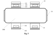
- At least a part of the liquid operation compartment, the purification compartment, the transfer compartment, the amplification compartment, the monoclonal picking compartment and the loading and unloading compartment are arranged in a compartment body capable of being closed tightly, the compartment body including a laminar flow unit to put corresponding compartments in a controlled laminar flow environment.
- the laminar flow unit comprises a laminar air-supply unit including an air-supply fan or at least one filtering unit, and a laminar air-discharge unit including an air-discharge fan and a reverse filtering unit.
- an ultraviolet irradiation unit is provided in the compartment body.
- the liquid operation compartment comprises at least one pipetting unit
- the pipetting unit is mounted on a linear motor gantry main frame structure so as enable the pipetting unit to be movable along an X-axis
- each pipetting unit comprises one or more pipetting heads each of which is independently movable along a Y-axis and a Z-axis in the pipetting unit.
- each pipetting unit includes one or more movers mounted along a direction of the Y-axis to enable each pipetting head in each pipetting unit to be movable along the Y-axis under driving of the movers, and each pipetting unit further comprises a Z-axis driving mechanism to drive each pipetting head in each pipetting unit to move along the Z-axis.
- the liquid operation compartment further comprises one or more of a liquid pumping unit, a pump set array, a bottom-compartment liquid storage unit, a consumable stage sliding table array, an oscillation unit, a consumable carrier and an operation stage.
- the liquid operation compartment includes two or more pipetting units, which are configured to be able to perform operations independently of each other as well as to perform operations in parallel.
- the purification compartment comprises at least one purification pipetting unit
- the at least one purification pipetting unit is mounted on a linear motor gantry main frame structure, so as to enable the at least one purification pipetting unit to be movable along an X-axis
- each purification pipetting unit comprises one or more purification pipetting heads each of which is independently movable along a Y-axis and a Z-axis in the purification pipetting unit.
- the purification compartment further comprises one or more of a liquid pumping unit, a consumable stage sliding table array, a bottom-compartment liquid storage unit, an oscillation unit, a consumable carrier, an operation stage and a temperature-controlled storage device.
- the monoclonal picking compartment comprises a monoclonal picking unit for picking monoclonal nucleic acid products from an orifice plate.
- the monoclonal picking unit comprises a multi-channel pick head assembly formed by integrating a plurality of pick head elements.
- the multi-channel pick head assembly is connected to an integrated gas path on-off valve group, which is capable of controlling each pick head element separately to enable each pick head element to independently move and to independently fulfill operations of picking the monoclonal nucleic acid products.
- the monoclonal picking unit is mounted on an X-Y linear motor gantry main frame structure, so as to enable the monoclonal picking unit to be movable along an X-axis and a Y-axis, and the monoclonal picking unit includes a Z-axis motor, so as to enable the monoclonal picking unit to be movable along a Z-axis.
- the monoclonal picking unit further comprises an image capturing assembly for identifying and localizing target nucleic acid products in the monoclonal picking process.
- the image capturing assembly includes: a camera for real-time determining positions of nucleic acid products to be picked; and an optical distance sensor for calibrating a vertical distance between tip ends of the pick head elements in the multi-channel pick head assembly and a surface of the orifice plate bearing the nucleic acid products to be picked, and for evaluating a surface flatness of the orifice plate.
- the monoclonal picking unit further comprises a bracket assembly including vertical support plates and a plurality of horizontal support plates extending perpendicular to the vertical support plates, and each horizontal support plate is provided with holes through which the plurality of pick head elements extend, so as to ensure accurate localization of the plurality of pick head elements.
- one of the plurality of horizontal support plates is also provided with a guiding and positioning mechanism for the plurality of pick head elements, so as to localize and guide vertical movement of the plurality of pick head elements in the multi-channel pick head assembly.
- an upper surface of a bottom horizontal support plate of the plurality of horizontal support plates is configured to function as a limiting surface for each pick head element in the multi-channel pick head assembly, in order to ensure that the tip ends of the plurality of pick head elements are at a same height.
- the optical distance sensor and/or the camera are also arranged on the upper surface of the bottom horizontal support plate.
- each pick head element includes a first section and a second section, both of which are configured to be in floating connection.
- each pick head element includes a floating connection mechanism which includes a sleeve element and a floating element, the floating element is configured to be mountable in the sleeve element and capable of floating a distance within the sleeve element.
- an upper end of the first section of each pick head element is connected with a drive control valve to drive vertical movement of the pick head element by the drive control valve, and a lower end of the first section of each pick head element is secured within the sleeve element of the floating connection mechanism.
- the lower end of the first section of each pick head element includes a threaded joint for threadedly connecting the lower end of the first section to the sleeve element of the floating connection mechanism.
- each pick head element further includes a guide element.
- each pick head element further comprises a guide element arranged on an outer periphery of the second section of the pick head element.
- the guide element is configured as a guide bearing.
- each pick head element is made of SUS316 stainless steel material.
- the monoclonal picking compartment further comprises one or more of an oscillation-coating unit, a multi-channel pipetting unit, a liquid pumping unit, a bottom-compartment liquid storage unit, a consumable stage sliding table array, an operation stage, and a temperature-controlled storage device.
- the monoclonal picking compartment further comprises an oscillation-coating unit for realizing uniform distribution of flora on the orifice plate
- the oscillation-coating unit comprises a clamping mechanism and a cam oscillating mechanism, the orifice plate capable of being clamped in the clamping mechanism and oscillated together with the clamping mechanism under the drive of the cam oscillating mechanism.
- the monoclonal picking compartment further comprises a pick head cleaning assembly including at least one pick head cleaning element, for cleaning the multi-channel pick head assembly of the monoclonal picking unit.
- the pick head cleaning assembly further comprises a pick head drying unit including a heating unit, for drying the pick head elements in the multi-channel pick head assembly of the monoclonal picking unit.
- the pick head drying unit includes an air-supply duct and an air-discharge duct, for cooling the pick head elements in the multi-channel pick head assembly of the monoclonal picking unit that have been dried.
- control system includes a control computer, an I/O data collecting module, and a drive module.
- control system comprises a software system, which includes one or more of a workflow editing unit, a device monitoring and operating unit, a device debugging unit, a data storage unit, a log prompting unit, and a parameter setting unit.
- the intelligent system for gene synthesis and monoclonal picking further comprises at least one of the following modules: a sequencer module for detecting, confirming and screening synthesized gene fragments in the process of gene synthesis and monoclonal picking; and a material storage module for storing various materials required in the process of gene synthesis and monoclonal picking.
- references to a feature that is disposed “adjacent" another feature may have portions that overlap, overlie or underlie the adjacent feature.
- the intelligent system for gene synthesis and monoclonal picking may include a core operation module 1, a control system 10, and optionally a sequencer module 2 and/or a material storage module 3.
- the core operation module 1 is used to perform operations associated with gene synthesis and monoclonal picking, for example, core operations such as primer or gene synthesis, PCR amplification, vector amplification, product purification, monoclonal picking and the like.
- the sequencer module 2 is used to detect, confirm and screen synthesized gene fragments in the process of gene synthesis and monoclonal picking, and the like.
- the sequencer module 2 may include various required sequencers.
- the material storage module 3 is used to store various materials such as various consumables, reagents and the like that are required in the process of gene synthesis and monoclonal picking, so as to meet the demand for high-throughput continuous production.
- the control system 10 is used to control at least a part of operations of corresponding modules of the intelligent system for gene synthesis and monoclonal picking according to the present disclosure (for example, at least a part of operations of the core operation module 1), so as to at least partially or completely realize the automation and intelligentization of the intelligent system for gene synthesis and monoclonal picking according to the present disclosure.
- the core operation module 1 may include at least a part or all of a loading and unloading compartment 4, a liquid operation compartment 5, a purification compartment 6, a monoclonal picking compartment 7, an amplification compartment 8, and a transfer compartment 9.
- the loading and unloading compartment 4 is used to replenish various materials (such as samples for synthesis, synthetizing reagents, consumables in operations and so on) that are required in the process of gene synthesis and monoclonal picking, and to deliver products out after operation.
- the loading and unloading compartment 4 may include loading and unloading drums.
- the liquid operation compartment 5 is used to perform operations such as mixing gene fragments, mixing the synthetizing reagents with the samples for synthesis, and the like in the process of gene synthesis.
- the purification compartment 6 is used to purify nucleic acid products created after the mixing.
- the monoclonal picking compartment 7 is used to coat the purified nucleic acid products and to perform monoclonal picking on the cultured flora.
- the amplification compartment 8 is used to perform amplification operations and error correction operations on fragments of the nucleic acid products and to perform culturing and amplification operations on vector bacteria.
- the transfer compartment 9 is used to transfer the samples and/or materials among the respective compartments.
- the transfer compartment 9 may include a transfer robot.
- the transfer robot can carry out various transfer operations under the control of the control system 10. In an embodiment according to the present disclosure, some operations such as concentration detection and centrifugal enrichment may also be performed on the nucleic acid products in the transfer compartment 9.
- a different number of the loading and unloading compartment 4, the liquid operation compartment 5, the purification compartment 6, the monoclonal picking compartment 7, the amplification compartment 8 and the transfer compartment 9 may be provided in the core operation module 1 according to different process requirements, and these compartments may be arranged in any suitable ways in the core operation module 1. For example, referring to Figs.
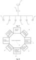
- the transfer compartment 9 may be arranged at a middle position of the core operation module 1, the loading and unloading compartment 4, the liquid operation compartment 5 and the purification compartment 6 may be arranged at a first side of the transfer compartment 9, and the monoclonal picking compartment 7 and the amplification compartment 8 may be arranged at a second side opposing the first side of the transfer compartment 9.
- the transfer compartment 9 may be arranged at a middle position of the core operation module 1, the liquid operation compartment 5 and the monoclonal picking compartment 7 may be arranged at a first side of the transfer compartment 9, two purification compartments 6 may be arranged at a second side opposing the first side of the transfer compartment 9, and the loading and unloading compartment 4 may be arranged at an end of the transfer compartment 9.
- the amplification compartment 8 may be arranged at any other suitable position. Referring to Fig.
- the loading and unloading compartment 4, the liquid operation compartment 5, the purification compartment 6, the monoclonal picking compartment 7, the amplification compartment 8, and the transfer compartment 9 may be in a star configuration.
- the transfer compartment 9 may be arranged at a central position of the core operation module 1, while the loading and unloading compartment 4, the liquid operation compartment 5, the purification compartment 6, the monoclonal picking compartment 7 and the amplification compartment 8 may be arranged around the transfer compartment 9 along a circumference.
- some spaces may also be reserved along the circumference to arrange compartments or detection instruments for other operations.
- a separate coating compartment, PCR amplification and ELISA compartment and the like may also be arranged along the circumference.
- these compartments may be arranged in a compartment body 100 that can be closed tightly.
- the airtightness of the compartment body 100 can be effectuated by a locked sealing door 20.
- the compartment body 100 may include a laminar flow unit to enable each compartment to be located in a controlled laminar flow environment, so that an internal environment of the core operation module 1 is isolated from its external environment.
- the laminar flow unit may include a laminar air-supply unit 18 and a laminar air-discharge unit 19 to form a circularly flowing laminar flow atmosphere in the compartment body 100.
- the laminar air-supply unit 18 may be provided on the top of the compartment body 100, while the laminar air-discharge unit may be provided at the bottom of the compartment body 100.
- the laminar air-supply unit 18 may include an air-supply fan 182, a primary filtering unit 181, and a secondary filtering unit 182.
- the primary filtering unit 181 and the secondary filtering unit 182 are configured to filter out contaminants (for example, various particulate matters or other impurities) in laminar gases before the laminar gases enter the interior of the compartment body 100.
- the primary filtering unit 181 and the secondary filtering unit 182 may include a filter screen.
- the laminar air-discharge unit 19 may include an air-discharge fan 191 and a reverse filtering unit 192.
- the reverse filtering unit 192 is configured to prevent contaminants in the external environment from entering the interior of the compartment body 100.
- the reverse filtering unit 192 may include a filter screen.
- an ultraviolet irradiation unit may be provided in the compartment body 100 for ultraviolet disinfection of the devices in the compartment body 100.
- the amplification compartment 8 and other incubators may not be in the laminar flow environment. Therefore, the amplification compartment 8 and other incubators may be arranged outside the compartment body 100.
- the liquid operation compartment 5 is used to perform operations such as mixing gene fragments and mixing the synthetizing reagents with the samples for synthesis, in the operational process of gene synthesis.
- the liquid operation compartment 5 may include at least one pipetting unit 502, for example, one, two or more pipetting units.
- the pipetting unit 502 is configured to transfer the liquid required in the process of gene synthesis to perform corresponding operations.
- the pipetting unit 502 may be configured to be movable along an X-axis.
- the pipetting unit 502 may be mounted on a linear motor gantry main frame structure 501 so as to be movable along the X-axis.
- Each pipetting unit 502 may include one or more pipetting heads 510, for example, one, two, four or more pipetting heads 510.
- Each pipetting head 510 can move independently along a Y-axis and a Z-axis in the pipetting unit 502, wherein the Y-axis is in a horizontal plane and perpendicular to the X-axis, and the Z-axis is in a vertical plane and perpendicular to the X-axis and the Y-axis.
- the pipetting unit 502 may include one or more movers mounted along a direction of the Y-axis, so that each pipetting head 510 can be driven by the movers to move along the Y-axis.
- the pipetting unit 502 may further include a Z-axis driving mechanism to drive each pipetting head 502 to move along the Z-axis.
- the pipetting unit 502 may be mounted on the linear motor gantry main frame structure 501 so as to be movable along the X-axis.
- the linear motor gantry main frame structure 501 may include two guide rail structures 511 spaced from each other and a cross beam 512 extending between the two guide rail structures 511.
- the guide rail structures 511 may extend along the X-axis, while the cross beam 512 may extend along the Y-axis.
- the cross beam 512 is movable along the X-axis over the guide rail structures 511.
- the pipetting unit 502 may be disposed on the cross beam 512 to move along the X-axis together with the cross beam 512 over the guide rail structures 511.
- the guide rail structures 511 and the cross beam 512 may be components of a linear motor, wherein the guide rail structures 511 may constitute a stator of the linear motor and the cross beam 512 may constitute a mover of the linear motor.
- the guide rail structures 511 and the cross beam 512 of the linear motor gantry main frame structure 501 can be connected in a non-mechanical manner.
- a gas gap 513 (the gas gap 513 may be maintained at millimeter level) is present between the guide rail structures 511 and the cross beam 512 in the working process due to the action of electromagnetic force.
- the pipetting unit 502 can be easily added, reduced, replaced or repaired on the linear motor gantry main frame structure 501.
- one or more pipetting units 502 may be conveniently mounted to the linear motor gantry main frame structure from a position above the cross beam 512 and along a direction F as shown in Fig.
- the pipetting unit 502 may be conveniently removed from a position above the cross beam 512 of the linear motor gantry main frame structure 501 and along a direction opposite to the direction F after the electrical connection is disconnected.
- the liquid operation compartment 5 may include a liquid pumping unit 504 and a pump set array 503.
- the liquid pumping unit 504 is configured to pump required process fluids into liquid storage tanks in the liquid operation compartment 5, and transfer the process fluids to the pipetting unit 502 by a robot (for example, an orifice plate robot).
- the liquid operation compartment 5 may further comprise a bottom-compartment liquid storage unit 506 for storing process fluids and capable of performing temperature control on the process fluids.
- the pump set array 503 may be equipped with a multi-channel peristaltic pump or other types of pumps, for pumping the process liquids in the bottom-compartment liquid storage unit 506 into pipes of units (such as the liquid pumping unit 504 and the like) provided on the working table-board. After the liquid pumping operation, the pipes may be subjected to full-automatic cleaning and closing operation, for example, with sterilized liquid.
- the pipetting unit 502 is configured to transfer the liquid required in the process to consumables (such as orifice plates) to perform corresponding operations.
- the liquid operation compartment 5 may also include a corresponding operation area.
- the liquid operation compartment 5 may include one or more of a consumable stage sliding table array 505, an oscillation unit 507, a consumable carrier 508, and an operation stage 509.
- the operation stage 509 is configured to perform corresponding operations on materials and can realize attitude adjustment and temporary storage of the materials during the process.
- the operation stage 509 may be arranged on the consumable stage sliding table array 505.
- the consumable stage sliding table array 505 can slide out of and into the liquid operation compartment 5 in a controlled manner, such that consumables such as orifice plates and the like can be loaded or unloaded onto or from the operation stage 509. As shown in Fig. 7 , the consumable stage sliding table array 505 can slide out of the liquid operation compartment 5, so as to facilitate the loading and removal of the consumables.
- the oscillation unit 507 is configured to perform blending operations on the consumables such as orifice plates and the like in the process, while the consumable carrier 508 is configured to carry different types of consumables, such as orifice plates, shake tubes, shake flasks and the like.
- the liquid operation compartment 5 may include two or more pipetting units 502, which enables the liquid operation compartment 5 to improve the utilization efficiency of the system through real-time resource optimization.
- the two or more pipetting units in the liquid operation compartment can operate independently or in parallel in two or more independent operation areas.
- the two pipetting units 502 in the liquid operation compartment 5 can operate independently or in parallel in two independent operation areas.
- the operation efficiency can be improved by orders of magnitude.
- the two or more pipetting units 502 may be integrated together (for example, they may be integrated into an 8-channel pipetting unit) for integral operation, as shown in the right figure of Fig. 10 , thereby realizing high-throughput operation.
- Fig. 12 shows an operation flow of mixing gene fragments in the liquid operation compartment 5.
- a 96-well or 384-well primer source plate may be grabbed from a primer stack rack in the material storage module 3 and transferred to a corresponding primer source plate position in the liquid operation compartment 5, the information of the corresponding primer source plate is recorded, and then a cover of the 96-well or 384-well primer source plate may be removed.
- the control system 10 may be used to control the robot in the transfer compartment 9 to grab and transfer the 96-well or 384-well primer source plate and remove the cover thereof.
- the control system 10 may also be used to control a corresponding scanning device to scan and record the information of the corresponding primer source plate.
- a blank 96-well or 384-well primer target plate is transferred to the mixing position, and the information of the blank 96-well or 384-well primer target plate at the mixing position is recorded (for example, using a scanning device for scanning codes and recording).
- a gene fragments mixing program may be started, a mixing table is read, and a mixing operation is started to mix the gene fragments, thereby obtaining a primer plate with mixed gene fragments.
- the primers in 8-20 wells of the primer source plate may be transferred to one well of the primer target plate.
- the purification compartment 6 may include at least one purification pipetting unit 602, for example, one, two or more purification pipetting units, to transfer nucleic acid samples required for purification operation in the purification process.
- the purification pipetting unit 602 may include one or more purification pipetting heads, for example, one or more 96-channel purification pipetting heads, to transfer materials (for example, nucleic acid samples) between different stations.
- the purification pipetting head can move independently along the Y-axis and the Z-axis in the purification pipetting unit 602.
- the purification pipetting unit 602 may be mounted on a linear motor gantry main frame structure 601 so as to be movable along the X-axis.
- the linear motor gantry main frame structure 601 may have the same structure as the linear motor gantry main frame structure 501, and thus will not be described here in detail.
- the purification compartment 6 may also include: a liquid pumping unit 603 for replenishing purifying reagents into reagent tanks in the purification compartment 6; a consumable stage sliding table array 604 capable of sliding out of and into the purification compartment 6 in a controlled manner so as to facilitate loading and unloading of consumables such as orifice plates; a bottom-compartment liquid storage unit 605 for storing process fluids and capable of performing temperature control on the process fluids; an oscillation unit 606 for performing mixing operation on consumables such as orifice plates during the purification operation; a consumable carrier 607 for carrying different types of consumables such as orifice plates and the like; and an operation stage 608 for attitude adjustment and temporary storage of materials during the purification operation.
- a liquid pumping unit 603 for replenishing purifying reagents into reagent tanks in the purification compartment 6
- a consumable stage sliding table array 604 capable of sliding out of and into the purification compartment 6 in a controlled manner so as to facilitate loading and unloading
- the purification compartment 6 may further include a temperature-controlled storage device 609 for temporarily storing nucleic acid samples at a controlled temperature during operation.
- the temperature-controlled storage device 609 may be a 4 °C temperature-controlled storage device, so it can store nucleic acid samples at a temperature of 4 °C .
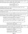
- Fig. 14 shows an operation flow of performing purification operation in the purification compartment 6.
- This operation flow may comprise: grabbing a PCR reaction orifice plate, which has finished reaction, from a PCR reaction orifice plate stack rack first and transferring it to an orifice plate carrier, scanning codes and recording the PCR reaction orifice plate, and opening a cover of the PCR reaction orifice plate; then, grabbing a magnetic bead plate from a purifying reagent stack rack and transferring it to a magnetic bead carrier; acquiring a purifying reagent; adding a predetermined amount of the purifying reagent into the PCR reaction orifice plate and mixing them uniformly.
- the above operation steps may be repeated until all of the PCR reaction orifice plates are filled with a predetermined amount of the purifying reagent; next, keeping the uniformly-mixed PCR reaction orifice plates at room temperature for a predetermined period of time and then transferring them to a magnetic frame to remove waste liquids; later, transferring the PCR reaction orifice plates having the waste liquids removed to the PCR reaction orifice plate stack rack, adding a predetermined amount of cleaning buffer solution into them and mixing them uniformly, and then standing them for a predetermined time to remove further waste liquids from the PCR reaction orifice plates, thus completing the purification operation.
- the monoclonal picking compartment 7 may include a monoclonal picking unit 702 for picking biological samples such as monoclonal bacterial strains or cell strains from the orifice plate (for example, an agar plate).
- the monoclonal picking unit 702 may be mounted on a linear motor gantry main frame structure 701 to be transferred to a target orifice plate position.
- the linear motor gantry main frame structure 701 may be an X-Y linear motor gantry main frame structure, so as to be able to transfer the monoclonal picking unit 702 along the X-axis and the Y-axis.
- the linear motor gantry main frame structure 701 may have the same structure as the linear motor gantry main frame structure 501 and thus will not be described here in detail.
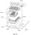
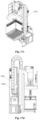
- the monoclonal picking unit 702 may include a multi-channel pick head assembly 7026 (for example, 4-, 8-, 16-, 24-, 48- or 96-channel pick head assembly) formed by integrating a plurality of (for example, 4, 8, 16, 24, 48 or 96) pick head elements 7024 together.
- the multi-channel pick head assembly may be connected to an integrated gas path on-off valve group 7025 so as to carry out picking operation under the control of the integrated gas path on-off valve group 7025.
- the integrated gas path on-off valve group 7025 can control each pick head element 7024 separately, so that each pick head element 7024 is capable of independently moving and fulfilling the operation of picking monoclonal bacterial strains or cell strains independently.
- the monoclonal picking unit 702 may also include only one picking unit 7024, thus forming a single-channel pick head assembly.
- the monoclonal picking unit 702 may include a Z-axis motor 7021.
- the multi-channel pick head assembly can be driven by the Z-axis motor 7021 to move up and down along a direction of the Z-axis.
- the Z-axis motor 7021 can drive the multi-channel pick head assembly to move up and down along the direction of the Z-axis via a gear-rack mechanism 7032.
- the monoclonal picking unit 702 may include an image capturing assembly 703 for identifying and localizing the target biological sample such as the target bacterial strain or the target cell strain in the monoclonal picking process.
- the image capturing assembly 703 may include a camera 7023. The camera can capture images of the target orifice plate in real time to determine the position of the biological sample such as the target bacterial strain or the target cell strain to be picked.
- the camera after having determined the position of the biological sample such as the target bacterial strain or the target cell strain to be picked, can also send a position adjustment signal to a linear motor provided on the linear motor gantry main frame structure 701, so as to move the multi-channel pick head assembly to the target position.
- the image capturing assembly 703 may also include an optical distance sensor 7022. The optical distance sensor can be used to calibrate a vertical distance between tip ends of the pick head elements in the multi-channel pick head assembly and a surface of the target orifice plate, and to evaluate a surface flatness of the target orifice plate.
- the optical distance sensor after having calibrated the vertical distance between the tip ends of the pick head elements in the multi-channel pick head assembly and the surface of the target orifice plate, can send a height adjustment signal to the Z-axis motor 7021 to move the multi-channel pick head assembly up and down along the direction of the Z-axis to a predetermined height.
- the monoclonal picking unit 702 may include a bracket assembly 7027.
- the bracket assembly 7027 may include vertical support plates 7028 and a plurality of horizontal support plates 7029 extending perpendicular to the vertical support plate 7028.
- Each horizontal support plate 7029 is provided with holes through which the plurality of pick head elements 7024 extend, to ensure the accurate localization of the plurality of pick head elements 7024.
- one of the plurality of horizontal support plates 7029 is further provided with a guiding and positioning mechanism 7031 for the plurality of pick head elements 7024, in order to localize and guide the vertical movement of the plurality of pick head elements 7024 in the multi-channel pick head assembly 7026.
- an upper surface 7030 of a bottom horizontal support plate of the plurality of horizontal support plates 7029 functions as a limiting surface for each pick head element 7024 in the multi-channel pick head assembly 7026, in order to ensure that the tip ends of the plurality of pick head elements 7024 are at a same height.
- the upper surface of the bottom horizontal support plate may be formed in a single processing step to ensure its accuracy, so that the tip end of each pick head element 7024 can be positioned more accurately, and the tip ends of the plurality of pick head elements 7024 can be arranged at the same height more accurately. Further, as shown in Fig.
- the optical distance sensor 7022 may also be arranged on the upper surface 7030 of the bottom horizontal support plate so as to accurately calibrate the vertical distance between the tip ends of the pick head elements 7024 in the multi-channel pick head assembly 7026 and the surface of the target orifice plate.
- the camera 7023 may also be arranged on the upper surface 7030 of the bottom horizontal support plate.
- the pick head element 7024 may include a first section 70241 and a second section 70242.
- An upper end of the first section 70241 is connected with a drive control valve 70243 in the integrated gas path on-off valve group 7025, such that the vertical movement of the pick head element 7024 can be driven by the drive control valve 70243.
- a lower end of the first section 70241 and an upper end of the second section 70242 are configured in a floating connection to ensure that the tip ends of the plurality of pick head elements 7024 can be more easily positioned at the same height, which allows a reduction in the assembling difficulty of the multi-channel pick head assembly 7026 and a reduction in the machining accuracy of the bracket assembly 7027.
- the pick head element 7024 may include a floating connection mechanism to realize the floating connection between the lower end of the first section 70241 and the upper end of the second section 70242.
- the floating connection mechanism may include a sleeve element 70244 and a floating element 70245.
- the floating element 70245 may be configured as a floating ferrule and may be fixedly connected with the upper end of the second section 70242.
- the floating element 70245 is configured to be mountable in the sleeve element 70244 and capable of floating a distance within the sleeve element 70244 (for example, floating up and down over a distance in the vertical direction).
- the lower end of the first section 70241 may also be fixed in the sleeve element 70244, thus achieving a floating connection with the second section 70242.
- the lower end of the first section 70241 may include a threaded joint 70246 for threadedly connecting the lower end of the first section 70241 to the sleeve element 70244.
- the pick head element 7024 may further include a guide element 70247.
- the guide element 70247 may be disposed on an outer periphery of the second section 70242 of the pick head element 7024.
- the guide element 70247 may be configured as a guide bearing.
- the guide element 70247 may extend through the guiding and positioning mechanism 7031 provided on one of the horizontal support plates to guide the vertical movement of the pick head element 7024.
- the guide element 70247 may be made of a wear-resistant material to prevent the occurrence of dust and particle contamination caused by friction during movement.
- the tip end of the second section 70242 of the pick head element 7024 is used to perform the picking operation.
- the tip end of the pick head element 7024 may be appropriately shaped to reach the best picking effect and transfer safety, and to be prevented from falling during transfer.
- the pick head element 7024 may be made of SUS316 stainless steel material that meets GMP requirements to maintain the cleanliness of the picked sample.
- the adoption of the bracket assembly 7027 can realize modular design of the monoclonal picking unit 702. This not only allows any arbitrary integration from a single-channel pick head assembly to any number of the multi-channel pick head assemblies, but also can ensure the accuracy of the relative position between the pick head elements in the multi-channel pick head assembly.
- Fig. 19 shows an operation flow of monoclonal picking with the monoclonal picking unit 702.
- the monoclonal picking unit 702 is transferred to a target orifice plate position by a linear motor provided on the linear motor gantry main frame structure 701 to complete the preliminary aiming operation.
- the height distance that is, the vertical distance between the tip ends of the pick head elements in the multi-channel pick head assembly and the surface of the target orifice plate to be picked
- the camera 7023 may be used to capture the image of the target orifice plate to be picked in real time to real-time calculate the position of the target bacterial strain or cell strain and transmit the calculated result to the control system, which sets the picking sequence schedule based on the real-time position of the target bacterial strain or cell strain. Thereafter, the control system selects the position of the target bacterial strain or cell strain to be picked, and sends a position adjustment signal to the linear motor provided on the linear motor gantry main frame structure 701, so as to move the multi-channel pick head assembly of the monoclonal picking unit 702 to a position precisely aligned with the target bacterial strain or cell strain to be picked.
- the position of the target bacterial strain or cell strain to be picked can be re-determined using the camera 7023, and fine adjustment may be performed using the Z-axis motor 7021 to move the multi-channel pick head assembly to a predetermined height matching the picking position.
- a single one of the drive control valve 70243 in the integrated gas path on-off valve group 7025 may be started to allow the corresponding single pick head element 7024 to move up and down under the control of the single drive control valve 70243 to thereby carry out the picking operation.
- another target is selected for monoclonal picking, and one or more of the above steps may be repeated until a predetermined number of targets have been subjected to monoclonal picking.
- the multi-channel pick head assembly may be moved to a multi-well orifice plate (for example, a 96-well plate), and then all the biological samples picked are eluted to said multi-well orifice plate.
- a multi-well orifice plate for example, a 96-well plate
- the monoclonal picking compartment 7 may further include an oscillation-coating assembly 709 for realizing uniform distribution of flora on the orifice plate (e.g., an agar plate) so as to enable high-efficiency culturing of the monoclonal flora and prepare for high-throughput monoclonal picking.
- the monoclonal picking compartment 7 may further include a multi-channel pipetting unit 705 and a liquid pumping unit 706.
- the multi-channel pipetting unit 705 is configured to transfer fluids between different operating positions, for example, it may be used to pick liquids such as reagents and culture media and fill them into the wells of the orifice plate, and it may also be used to transfer synthesized biological samples between different operating positions.
- the multi-channel pipetting unit 705 may include different numbers of channels based on the required process. As shown more clearly in Fig. 15 , the multi-channel pipetting unit 705 may also be arranged on the linear motor gantry main frame structure 701 to be moved along the X-axis and/or the Y-axis under the drive of the linear motor in the linear motor gantry main frame structure 701 to thereby transfer fluids between different stations.
- the liquid pumping unit 706 is used to add fluids such as culture media and picking reagents into the reagent tank of the monoclonal picking compartment 7.
- the oscillation-coating assembly 709 may include a clamping mechanism 7091 and a cam oscillating mechanism 7092.
- the orifice plate (for example, an agar plate) may be clamped in the clamping mechanism 7091 and oscillated together with the clamping mechanism 7091 under the drive of the cam oscillating mechanism 7092, so as to realize the uniform distribution of flora on the orifice plate.
- the cam oscillating mechanism 7092 may be driven by a drive motor 7093.
- the oscillation-coating assembly 709 may further include an in-situ sensor 7094 for detecting a reference position of the oscillation-coating assembly 709.
- Fig. 21 shows an operation flow of coating flora on an orifice plate with the oscillation-coating assembly 709 according to an embodiment of the present disclosure.
- the orifice plate for example, an agar plate
- the oscillation-coating assembly 709 first and clamped in the clamping mechanism 7091.
- a process fluid is filled in each well of the orifice plate using the multi-channel pipetting unit 705, and the rotational speed of the cam oscillating mechanism 7092 is set to drive the clamping mechanism 7091 and the orifice plate therein to oscillate at the set rotational speed, thereby realizing uniform coating of the process fluid on the surface of the orifice plate.
- a cell/bacteria solution is added onto the surface of the orifice plate using the multi-channel pipetting unit 705, and the rotational speed of the cam oscillating mechanism 7092 is set to drive the clamping mechanism 7091 and the orifice plate therein to oscillate at the set rotational speed, thereby realizing uniform coating of the cell/bacteria on the surface of the orifice plate.
- a pick head cleaning assembly 704 may be provided in the monoclonal picking compartment 7.
- the pick head cleaning assembly 704 may include a plurality of pick head cleaning elements, such as a first pick head cleaning element 7041, a second pick head cleaning element 7042, and a third pick head cleaning element 7043 as shown in Fig. 22 .
- Each of the pick head cleaning elements may contain liquids (such as alcohol, etc.) for cleaning the pick head.
- the pick head cleaning assembly 704 may further include a pick head drying element 7044.
- the pick head drying element 7044 may include a heating unit to ensure quick drying of the pick head element.
- the pick head drying element 7044 may also include an air-supply duct and an air-discharge duct to realize rapid cooling of the pick head elements that have been dried.
- Fig. 23 shows the specific structure of the pick head drying element 7044 according to an embodiment of the present disclosure.
- the pick head drying element 7044 may include a heating unit 7047.
- the heating unit 7047 may include a plurality of heating elements, such as electric heating wires, electric heating rods, irradiation heating lamps, and the like.
- the pick head drying element 7044 may include two air inlets 7045 and 7046 provided on the left and right sides thereof, and an air outlet 7048 arranged in a vertical direction between the two air inlet holes 7045 and 7046.
- the air inlets 7045 and 7046 and the air outlet 7048 are configured to be in fluid communication with each other, so that air can enter the interior of the pick head drying element 7044 through the air inlets 7045 and 7046 and be discharged from the interior of the pick head drying element 7044 through the air outlet 7048, thereby realizing rapid air cooling of the pick head.
- the pick head drying element 7044 may include an air-supply device to send air into the interior of the pick head drying element 7044 through the air inlets 7045 and 7046.
- Fig. 24 shows an operation flow of cleaning the pick head element with the pick head cleaning assembly 704 according to an embodiment of the present disclosure.
- a plurality of pick head cleaning elements 7041, 7042 and 7043 may be used to clean the pick head elements in turn, and then the cleaned pick heads are transferred to the pick head drying element 7044.
- the cleaned pick head elements are first heated by the heating unit 7047 to evaporate the cleaning liquid remaining on the pick head element, and then air is sent into the interior of the pick head drying element 7044 by the air-supply device to cool the heated pick head elements to return them to the normal temperature.
- the monoclonal picking compartment 7 may also include: a bottom-compartment liquid storage unit 708 for storing process fluids and capable of performing temperature control on the process fluids; a consumable stage sliding table array 707 capable of fully automatically sliding in and out of the monoclonal picking compartment 7, so as to facilitate the loading of consumables such as orifice plates, reagent tanks and the like; a consumable carrier 710 for carrying different types of consumables such as orifice plates, shake tubes, shake flasks and the like according to actual process requirements; an operation stage 711 used to perform corresponding operations on materials and capable of realizing attitude adjustment and temporary storage of the materials during the process.
- a bottom-compartment liquid storage unit 708 for storing process fluids and capable of performing temperature control on the process fluids
- a consumable stage sliding table array 707 capable of fully automatically sliding in and out of the monoclonal picking compartment 7, so as to facilitate the loading of consumables such as orifice plates, reagent tanks and the like
- the monoclonal picking compartment 7 may further include a temperature-controlled storage device 712 for temporarily storing nucleic acid samples at a controlled temperature during operation.
- the temperature-controlled storage device 712 may be a 4 °C temperature-controlled storage device, so it can store nucleic acid samples at a temperature of 4 °C.
- the intelligent system for gene synthesis and monoclonal picking may include the control system 10.
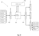
- Fig. 25 shows a basic architecture of the control system 10.
- the control system 10 may include a control computer 101, an I/O data collecting module 102, and a drive module 103.
- the I/O data collecting module 102 can collect various required data, including but not limited to temperature, humidity, pressure, weight, distance, etc., by means of various sensors, and send the collected data to the control computer 101.
- the control computer 101 can execute calculation based on various data collected by the I/O data collecting module 102, and issue various instructions to control the drive module 103 to perform various operations.
- control computer 101 may control the drive module 103 to execute control on pumps, valves, temperature as well as other actuating mechanisms.
- Said other actuating mechanisms include, but are not limited to, rotary motors, linear motors, electric sliding tables, cameras, and the like.
- the control system 10 may also include a laboratory data management system (LDMS)104, which may interact with the control computer 101 to store and/or read various necessary data.
- LDMS laboratory data management system
- control computer of the control system 10 may be equipped with a comprehensive software system 11 to ensure the full-automatic operation of the whole intelligent system for gene synthesis and monoclonal picking and realize the collection, storage and analysis of data during the operation.
- software system 11 may include, but is not limited to, the following units:
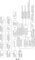
- FIGs. 6a-6b show various typical process flows of gene synthesis and monoclonal picking that can be performed using the system for gene synthesis and monoclonal picking or its core operation module 1 according to the present disclosure.
- primer synthesis and primer mixing may be carried out in the liquid operation compartment 5, then one or more rounds of PCR reaction (for example, two rounds of PCR reaction shown in Fig. 6a ) may be carried out in the amplification compartment 8 to obtain a PCR product, which is subsequently subjected to purifying operation in the purification compartment 6. Later, the purified PCR product may be subjected to an error correction reaction to obtain an error corrected product, and the error corrected product may be purified in further. Next, the error corrected product after purification may be subjected to connecting transformation (for example, connecting the primer fragments to vectors), coating, standing culture, and monoclonal picking operations to pick out the required cells/bacteria.
- connecting transformation for example, connecting the primer fragments to vectors
- the cells/bacteria picked out may be operated in two routes.
- the cells/bacteria picked out continue to be subjected to colony PCR operation to obtain colony PCR products; purification operation is performed on the colony PCR products to realize mixing of the purified colony PCR products; and then the purified colony PCR products can be subjected to high-throughput sequencing (NGS sequencing).
- the cells/bacteria picked out are directly subjected to oscillating culture, and then plasmid extraction is performed on the oscillating-cultured cells/bacteria.
- the cells/bacteria obtained by monoclonal picking may be transferred to a porous deep-well plate for the oscillating culture.
- a new multi-well plate for example, a 96-well plate
- plasmid small-amount-extraction preparing puncture bacteria, or using it as a seed solution for plasmid large-amount-extraction
- picking a bacteria solution with correct sequencing and transferring it to a multi-well plate such as a 24-well plate or a 96-well plate
- a multi-well plate such as a 24-well plate or a 96-well plate
- plasmid small-amount-extraction in the multi-well plate such as the 24-well plate or the 96-well plate
- the bacteria solution as a seed solution for plasmid large-amount-extraction
- the amount of personnel required in the process from gene synthesis to monoclonal picking can be reduced by orders of magnitude and the processing throughput in the whole process can be increased by orders of magnitude, thereby meeting the requirements for efficiency and effectiveness in the process of research, development and evaluation of new drugs and effectively reducing costs. Meanwhile, it can also realize the intensive use of core device units in the process and reduce the requirements for use space by orders of magnitude.
- the standardized system and supporting technology facilitate the flexible arrangement of the system and the promotion of the standardized method in different locations.
- replacement of the manual operation with the automatic system can solve problems related to stability, uniformity and reproducibility in the operation process.
- the biological safety of the samples, environment and operators can be effectively guaranteed, and confusion and cross-contamination between the samples can be strictly avoided in the operation process.
- the adoption of the software system enables standardized collection, storage and analysis of data in the operation process, not only improving the efficiency of analysis and screening, but also realizing intelligent docking with upstream and downstream automatic systems.
- the present disclosure also provides a technical solution as following:
- An intelligent system for gene synthesis and monoclonal picking comprises a core operation module 1, a sequencer module 2, a material storage module 3 and a control computer 10.
- the core operation module 1 includes a loading and unloading compartment 4, a liquid operation compartment 5, a purification compartment 6, a monoclonal picking compartment 7, an amplification compartment 8 and a transfer compartment 9.
- the liquid operation compartment 5 includes a linear motor gantry main frame 501, a pipetting unit 502, a pump set array 503, a unit for pumping and replenishing liquid 504, a first consumable stage sliding table array 505, a first bottom-compartment liquid storage unit 506, a first oscillation unit 507, a first consumable carrier 508 and a first operation stage 509.
- the purification compartment 6 includes a first X-Y linear motor gantry structure 601, a 96-channel purification pipetting head 602, a first liquid pumping unit 603, a second consumable stage sliding table array 604, a second bottom-compartment liquid storage unit 605, a second oscillation unit 606, a second consumable carrier 607, a second operation stage 608 and a first 4 °C temperature-controlled storage device 609.
- the monoclonal picking compartment 7 includes a second X-Y linear motor gantry structure 701, a 96-channel monoclonal picking unit 702, an orifice plate image capturing assembly 703, a pick head sterilizing and cleaning assembly 704, a multi-channel pipetting unit 705, a second liquid pumping unit 706, a third consumable stage sliding table array 707, a third bottom-compartment liquid storage unit 708, an oscillation-coating assembly 709, a third consumable carrier 710, a third operation stage 711 and a second 4 °C temperature-controlled storage device 712.
- a comprehensive control software 11 is installed in the control computer 10.
- the control software 11 is provided therein with a workflow editing unit 12, a full-automatic device monitoring and operating unit 13, a manual device debugging unit 14, a data storage unit 15, a log prompting unit 16 and a parameter setting unit 17.
- the loading and unloading compartment 4, the liquid operation compartment 5, the purification compartment 6, the monoclonal picking compartment 7, the amplification compartment 8 and the transfer compartment 9 are each provided with laminar air-supply units 18 on both sides of their top's center.
- the loading and unloading compartment 4, the liquid operation compartment 5, the purification compartment 6, the monoclonal picking compartment 7, the amplification compartment 8 and the transfer compartment 9 are each provided with laminar air-discharge units 19 on both sides of their bottom's center.
- the loading and unloading compartment 4, the liquid operation compartment 5, the purification compartment 6, the monoclonal picking compartment 7, the amplification compartment 8 and the transfer compartment 9 are each provided with locked sealing door bodies 20 on their both sides.
- the laminar air-supply unit 18 includes a primary filtering unit 181, an air-supply fan 182, and a secondary filtering unit 183.
- the laminar air-discharge unit 19 includes an exhaust fan 191 and a reverse filtering unit 192.
- the two pipetting units 502 when consumables such as a 24-well plate, a 6-well plate and an 8-well plate are operated in the liquid operation compartment 5, the two pipetting units 502 operate in parallel in the left and right independent areas, which is equivalent to two pipetting units 502 working in parallel, capable of improving operation efficiency by orders of magnitude.
- the two pipetting units 502 are integrated into an 8-channel pipetting unit, which can operate on the 96/384-well plate.
- a new module When functions are to be added, a new module can be conveniently mounted from a position above the gantry structure and can come into use only by connection with electrical cables; when the working unit needs to be replaced or repaired, the working unit can be conveniently removed from a position above the gantry after the electrical connection is disconnected.
- a millimeter-level gas gap is maintained between the X-axis guide rail and the Y-axis cross beam, which eliminates the mechanical friction and the resultant dust pollution, and at the same time gets rid of the requirement for grease lubrication by conventional servo structures and the pollution caused by grease volatilization.
- a typical automatic operation flow of mixing primer in the liquid operation compartment 5 is as follows: firstly, grabbing a 384/96-well primer plate from a primer plate stack rack, transferring it to a pipetting compartment, scanning codes and recording; removing a cover of the 384/96-well primer plate, transferring a blank 96-well deep-well plate to a mixing plate position, scanning codes and recording; finally, starting the gene fragment mixing program, reading the mixing table, transferring the primer in 8-20 wells of the source plate into one well of the target plate, and starting the automatic operation to mix the gene fragments to thereby obtain a primer plate.
- a typical automatic operation flow of purifying nucleic acids in the purification compartment 6 is as follows: firstly, grabbing a 96-well PCR reaction plate, which has finished reaction, from a stack rack and transferring it to an orifice plate carrier, scanning codes and recording, and removing the cover thereof; then grabbing a magnetic bead carrier from a purifying reagent stack rack and meanwhile grabbing the purifying reagent; adding an amount of (ul) purifying reagent into the PCR reaction plate, and blowing and mixing them evenly; later, grabbing the magnetic bead carrier from the purifying reagent stack rack and meanwhile grabbing a purifying reagent # 2; standing at room temperature for certain minutes; transferring the PCR reaction plate to a magnetic frame to remove the waste liquid; finally, transferring the PCR reaction plate to the orifice plate carrier, adding an amount of (ul) cleaning buffer solution, and blowing and mixing them evenly; and removing the waste liquid after standing for certain minutes.
- the 96-channel monoclonal picking unit 702 includes a Z-axis motor 7021, an optical distance sensor 7022, a camera 7023, a 96-channel pick head unit 7024, and an integrated gas path on-off valve group 7025.
- the basic flow of monoclonal picking is as follows: firstly, the 96-channel monoclonal picking unit 702 is transferred to a target orifice plate position by the second X-Y linear motor gantry structure 701 to fulfill the initial aiming; then, the second X-Y linear motor gantry structure 701 drives the 96-channel monoclonal picking unit 702 to enable the optical distance sensor 7022 to scan the surface flatness of the picked plate and calibrate the height distance thereof; the camera 7023 captures images in real time and calculates the real-time position of the target bacteria or cells, and the control computer 10 sets the picking sequence schedules; then, the position of the target bacteria or cells is selected, and the second X-Y linear motor gantry structure 701 moves to the precise aiming position; the orifice plate image capturing assembly 703 quickly confirms the position, and fine adjustment is performed using the Z-axis motor 7021 to move the pick head to a local height matching the picking position; a single-channel gas valve in the integrated gas path on-off valve group
- a next target is chosen for monoclonal picking by the same step as performed on the previous target until all the monoclonal picking products on the whole 96-well plate have been completely eluted.
- the pick heads in the 96-channel pick head unit 7024 have tip ends specially shaped to reach the best picking effect and transfer safety, and to be prevented from falling during transfer.
- the pick heads are made of SUS316 material that meets GMP requirements to keep the sample clean.
- the guide portion of the pick head is made of high wear-resistant materials, which meet FDA certification to avoid dust and particulate contamination during movement.
- the floating compensation and connection arrangement between the pick head and the driving mechanism reduces the processing and assembling difficulty while ensuring the relative accuracy of the multi-channel pick heads.
- the drive unit and the control element of the pick heads employ modular design, which can flexibly realize arbitrary throughput integration from single channel to 96 channels.
- the tip ends of the multi-channel pick heads are hard limited, and a flat surface formed in a single processing step ensures the accuracy of the descending distance of the pick heads.
- the mounting hole of the multi-channel pick heads is formed in a single processing step to ensure the accuracy of the relative position of the multi-channel pick heads.
- the multi-channel drive part fixing mechanism adopts modular design, which can flexibly realize arbitrary throughput integration from single channel to 96 channels.
- the pick head sterilizing and cleaning assembly 704 includes a pick head alcohol-cleaning tank 1# 7041, a pick head alcohol-cleaning tank 2# 7042, a pick head alcohol-cleaning tank 3# 7043, a pick head drying tank 7044, an air inlet 1# 7045, an air inlet 2# 7046, a heating unit array 7047 and an air outlet 7048.
- the basic flow of cleaning the pick head is as follows: the pick head is sent to the pick head alcohol-cleaning tank 1# 7041, the pick head alcohol-cleaning tank 2# 7042 and the pick head alcohol-cleaning tank 3# 7043 in order for cycling alcohol-cleaning; the heating unit array 7047 dries the pick head by heat source irradiation; and air flows in through the air inlet 1# 7045 and the air inlet 2# 7046 and is discharged through the air outlet 7048, whereby the flowing air may cool the pick head.
- the oscillation-coating assembly 709 includes a clamping structure 7091, a cam oscillating structure 7092, a drive motor 7093 and an in-situ sensor 7094.
- the basic process flow of oscillation coating is as follows: an agar plate to be coated is transferred into the oscillation-coating assembly 709; the multi-channel pipetting unit 705 fills the process liquid into each well of the agar plate; the drive motor 7093 drives the agar plate to oscillate through the cam oscillating structure 7092 based on the preset rotational speed, so as to realize uniform coating of the process liquid on the surface of the agar plate; the multi-channel pipetting unit 705 adds bacteria or cell solution to the surface of the agar plate; the drive motor 7093 drives the agar plate to oscillate through the cam oscillating structure 7092 based on the preset rotational speed, so as to realize uniform coating of the bacteria or cell solution on the surface of the agar plate.
- the workflow editing unit 12 has the functions of editing and managing the full-flow process list, providing a standardized process template, and controlling and adjusting the process in real time;
- the full-automatic device monitoring and operating unit 13 has the functions of managing the historical data of sample liquid operation, the historical data of sample magnetic beads operation, the historical data of sample coating operation, the historical data of sample monoclonal picking and the historical data of sample transferring operation, managing the state of materials at each station, monitoring the running state of modules of each device, managing the loading of solid consumables, managing the loading of liquid materials, managing the storage of consumables at the storage center, and managing the replenishment of consumables at the storage center;
- the manual device debugging unit 14 has the functions of calibrating and correcting each mobile module in the system, calibrating and correcting each liquid unit in the system, demonstrating the intelligent monoclonal sample picking, and demonstrating the sample coating process;
- the data storage unit 15 has the functions of storing original image data of monoclonal picking;
- the log prompting unit 16 has
Landscapes
- Chemical & Material Sciences (AREA)
- Life Sciences & Earth Sciences (AREA)
- Health & Medical Sciences (AREA)
- Engineering & Computer Science (AREA)
- Bioinformatics & Cheminformatics (AREA)
- Organic Chemistry (AREA)
- Wood Science & Technology (AREA)
- Zoology (AREA)
- Biotechnology (AREA)
- Biochemistry (AREA)
- General Health & Medical Sciences (AREA)
- General Engineering & Computer Science (AREA)
- Sustainable Development (AREA)
- Microbiology (AREA)
- Genetics & Genomics (AREA)
- Biomedical Technology (AREA)
- Analytical Chemistry (AREA)
- Molecular Biology (AREA)
- Physics & Mathematics (AREA)
- Computer Hardware Design (AREA)
- Immunology (AREA)
- Clinical Laboratory Science (AREA)
- Thermal Sciences (AREA)
- Cell Biology (AREA)
- General Physics & Mathematics (AREA)
- Pathology (AREA)
- Apparatus Associated With Microorganisms And Enzymes (AREA)
Abstract
An intelligent system for gene synthesis and monoclonal picking, comprising: a core operation module for performing operations associated with gene synthesis and monoclonal picking; and a control system for controlling at least a part of operations of corresponding compartments of the core operation module. The core operation module at least includes: a liquid operation compartment for performing operations of mixing gene fragments and mixing synthetizing reagents with biological samples in the process of gene synthesis; a purification compartment for performing purification operations on nucleic acid products created after the mixing; an amplification compartment for performing amplification operations and error correction operations on fragments of the nucleic acid products and performing culturing and amplification operations on vectors; and a monoclonal picking compartment for performing monoclonal picking operations on purified and cultured nucleic acid products.
Description
- The present disclosure generally relates to the technical field of biological drugs. More particularly, the present disclosure relates to an intelligent system for gene synthesis and monoclonal picking.
- Biological drugs are in a period of rapid development. Gene synthesis technology, as an important means for research, development and production of the biological drugs, has been widely applied. The whole process of the gene synthesis technology from primer synthesis to colony identification includes many complicated process steps. A large number of pipetting operations or the like need to be performed in the stage of gene synthesis and amplification. However, the conventional manual production mode or semi-automatic production mode is hard to meet the industrial large-scale production and the related delivery speed of the gene-synthesized drugs. In addition, with respect to the manual or the semi-automatic production mode, it is extremely difficult to increase the throughput due to some restrictions in the aspects of, for example, personnel's technical level and interaction of multiple devices, resulting in low production efficiency, high cost and low quality stability. In the conventional manual operation mode, it takes dozens of people to complete the whole process operation to reach relatively large-scale throughput. Therefore, the conventional manual operation mode requires a huge personnel team and a large venue, and requires, on the front line, highly skilled personnel who have been specially trained, resulting in high human resource costs to research institutions or enterprises. In addition, operation performed by different personnel will bring about some problems related to process stability, reproducibility and the like. Moreover, large-scale manual operation tends to produce confusion errors between samples.
- The genes, after having been synthetized, need to be transferred into vector cells/bacteria to be cultured. However, the conventional culturing system cannot be docked with automatic systems (such as robots with high degrees of freedom), so it is unable to realize arrayed culture, and accordingly makes it difficult to realize large-scale experimentation and production. After the vector cells/bacteria have been cultured, monoclonal screening is required to pick out the cells/bacteria that are suitable for continuous amplification for subsequent processes. In order to pick out suitable target cells/bacteria, tens of thousands of cells/bacteria need to be picked every day. However, in the case of manual operation, a single person can only pick hundreds of cells/bacteria every day, which is difficult to meet the demand of high-speed and large-scale research, development and production.
- Furthermore, in the conventional operation process, a large number of data need to be collected and analyzed for sample analysis and screening. The conventional manual operation mode tends to cause problems such as incomplete data recording, data loss, data conflict, the need for long-term data saving, and so on.
- One of objects of the present disclosure is to solve one or more of the above problems and realize other additional advantages.
- The present disclosure is intended to provide an intelligent system for large-scale gene synthesis and monoclonal picking, so as to achieve the purpose of high-volume production in the upstream process of research and development of macromolecular drugs, and to substantially realize high-throughput screening of the drugs. In addition, it is also expected to realize the online collection of enormous data while effectively replacing large-scale manual operation with intelligent or automatic large-scale operation, to thereby effectively improve the comprehensive efficiency of data collection, sorting, analysis and mining in the research and development process of the biological drugs.
- In an aspect of the present disclosure, an intelligent system for gene synthesis and monoclonal picking is provided, comprising: a core operation module for performing operations associated with gene synthesis and monoclonal picking; and a control system for controlling at least a part of operations of corresponding compartments of the core operation module. The core operation module at least includes: a liquid operation compartment for performing operations of mixing gene fragments and operations of mixing synthetizing reagents with biological samples in the process of gene synthesis; a purification compartment for performing purification operations on nucleic acid products created after the mixing; an amplification compartment for performing amplification operations and error correction operations on fragments of the nucleic acid products and performing culturing and amplification operations on vectors; and a monoclonal picking compartment for performing monoclonal picking operations on purified and cultured nucleic acid products.
- According to an embodiment of the present disclosure, the core operation module further comprises a loading and unloading compartment for replenishing various materials that are required in the process of gene synthesis and monoclonal picking.
- According to an embodiment of the present disclosure, the core operation module further comprises a transfer compartment for transferring biological samples and/or materials among at least a part of the liquid operation compartment, the purification compartment, the amplification compartment, the monoclonal picking compartment and the loading and unloading compartment.
- According to an embodiment of the present disclosure, the transfer compartment includes a transfer robot.
- According to an embodiment of the present disclosure, the transfer compartment is arranged at a middle position of the core operation module, while the liquid operation compartment, the purification compartment, the amplification compartment, the monoclonal picking compartment and the loading and unloading compartment are divided into two groups and arranged on both sides of the transfer compartment.
- According to an embodiment of the present disclosure, the transfer compartment is arranged at a central position of the core operation module, while the liquid operation compartment, the purification compartment, the amplification compartment, the monoclonal picking compartment and the loading and unloading compartment are arranged around the transfer compartment along a circumference.
- According to an embodiment of the present disclosure, at least a part of the liquid operation compartment, the purification compartment, the transfer compartment, the amplification compartment, the monoclonal picking compartment and the loading and unloading compartment are arranged in a compartment body capable of being closed tightly, the compartment body including a laminar flow unit to put corresponding compartments in a controlled laminar flow environment.
- According to an embodiment of the present disclosure, the laminar flow unit comprises a laminar air-supply unit including an air-supply fan or at least one filtering unit, and a laminar air-discharge unit including an air-discharge fan and a reverse filtering unit.
- According to an embodiment of the present disclosure, an ultraviolet irradiation unit is provided in the compartment body.
- According to an embodiment of the present disclosure, the liquid operation compartment comprises at least one pipetting unit, the pipetting unit is mounted on a linear motor gantry main frame structure so as enable the pipetting unit to be movable along an X-axis, and each pipetting unit comprises one or more pipetting heads each of which is independently movable along a Y-axis and a Z-axis in the pipetting unit.
- According to an embodiment of the present disclosure, each pipetting unit includes one or more movers mounted along a direction of the Y-axis to enable each pipetting head in each pipetting unit to be movable along the Y-axis under driving of the movers, and each pipetting unit further comprises a Z-axis driving mechanism to drive each pipetting head in each pipetting unit to move along the Z-axis.
- According to an embodiment of the present disclosure, the liquid operation compartment further comprises one or more of a liquid pumping unit, a pump set array, a bottom-compartment liquid storage unit, a consumable stage sliding table array, an oscillation unit, a consumable carrier and an operation stage.
- According to an embodiment of the present disclosure, the liquid operation compartment includes two or more pipetting units, which are configured to be able to perform operations independently of each other as well as to perform operations in parallel.
- According to an embodiment of the present disclosure, the purification compartment comprises at least one purification pipetting unit, the at least one purification pipetting unit is mounted on a linear motor gantry main frame structure, so as to enable the at least one purification pipetting unit to be movable along an X-axis, and each purification pipetting unit comprises one or more purification pipetting heads each of which is independently movable along a Y-axis and a Z-axis in the purification pipetting unit.
- According to an embodiment of the present disclosure, the purification compartment further comprises one or more of a liquid pumping unit, a consumable stage sliding table array, a bottom-compartment liquid storage unit, an oscillation unit, a consumable carrier, an operation stage and a temperature-controlled storage device.
- According to an embodiment of the present disclosure, the monoclonal picking compartment comprises a monoclonal picking unit for picking monoclonal nucleic acid products from an orifice plate.
- According to an embodiment of the present disclosure, the monoclonal picking unit comprises a multi-channel pick head assembly formed by integrating a plurality of pick head elements.
- According to an embodiment of the present disclosure, the multi-channel pick head assembly is connected to an integrated gas path on-off valve group, which is capable of controlling each pick head element separately to enable each pick head element to independently move and to independently fulfill operations of picking the monoclonal nucleic acid products.
- According to an embodiment of the present disclosure, the monoclonal picking unit is mounted on an X-Y linear motor gantry main frame structure, so as to enable the monoclonal picking unit to be movable along an X-axis and a Y-axis, and the monoclonal picking unit includes a Z-axis motor, so as to enable the monoclonal picking unit to be movable along a Z-axis.
- According to an embodiment of the present disclosure, the monoclonal picking unit further comprises an image capturing assembly for identifying and localizing target nucleic acid products in the monoclonal picking process.
- According to an embodiment of the present disclosure, the image capturing assembly includes: a camera for real-time determining positions of nucleic acid products to be picked; and an optical distance sensor for calibrating a vertical distance between tip ends of the pick head elements in the multi-channel pick head assembly and a surface of the orifice plate bearing the nucleic acid products to be picked, and for evaluating a surface flatness of the orifice plate.
- According to an embodiment of the present disclosure, the monoclonal picking unit further comprises a bracket assembly including vertical support plates and a plurality of horizontal support plates extending perpendicular to the vertical support plates, and each horizontal support plate is provided with holes through which the plurality of pick head elements extend, so as to ensure accurate localization of the plurality of pick head elements.
- According to an embodiment of the present disclosure, one of the plurality of horizontal support plates is also provided with a guiding and positioning mechanism for the plurality of pick head elements, so as to localize and guide vertical movement of the plurality of pick head elements in the multi-channel pick head assembly.
- According to an embodiment of the present disclosure, an upper surface of a bottom horizontal support plate of the plurality of horizontal support plates is configured to function as a limiting surface for each pick head element in the multi-channel pick head assembly, in order to ensure that the tip ends of the plurality of pick head elements are at a same height.
- According to an embodiment of the present disclosure, the optical distance sensor and/or the camera are also arranged on the upper surface of the bottom horizontal support plate.
- According to an embodiment of the present disclosure, each pick head element includes a first section and a second section, both of which are configured to be in floating connection.
- According to an embodiment of the present disclosure, each pick head element includes a floating connection mechanism which includes a sleeve element and a floating element, the floating element is configured to be mountable in the sleeve element and capable of floating a distance within the sleeve element.
- According to an embodiment of the present disclosure, an upper end of the first section of each pick head element is connected with a drive control valve to drive vertical movement of the pick head element by the drive control valve, and a lower end of the first section of each pick head element is secured within the sleeve element of the floating connection mechanism.
- According to an embodiment of the present disclosure, the lower end of the first section of each pick head element includes a threaded joint for threadedly connecting the lower end of the first section to the sleeve element of the floating connection mechanism.
- According to an embodiment of the present disclosure, each pick head element further includes a guide element.
- According to an embodiment of the present disclosure, each pick head element further comprises a guide element arranged on an outer periphery of the second section of the pick head element.
- According to an embodiment of the present disclosure, the guide element is configured as a guide bearing.
- According to an embodiment of the present disclosure, each pick head element is made of SUS316 stainless steel material.
- According to an embodiment of the present disclosure, the monoclonal picking compartment further comprises one or more of an oscillation-coating unit, a multi-channel pipetting unit, a liquid pumping unit, a bottom-compartment liquid storage unit, a consumable stage sliding table array, an operation stage, and a temperature-controlled storage device.
- According to an embodiment of the present disclosure, the monoclonal picking compartment further comprises an oscillation-coating unit for realizing uniform distribution of flora on the orifice plate, and the oscillation-coating unit comprises a clamping mechanism and a cam oscillating mechanism, the orifice plate capable of being clamped in the clamping mechanism and oscillated together with the clamping mechanism under the drive of the cam oscillating mechanism.
- According to an embodiment of the present disclosure, the monoclonal picking compartment further comprises a pick head cleaning assembly including at least one pick head cleaning element, for cleaning the multi-channel pick head assembly of the monoclonal picking unit.
- According to an embodiment of the present disclosure, the pick head cleaning assembly further comprises a pick head drying unit including a heating unit, for drying the pick head elements in the multi-channel pick head assembly of the monoclonal picking unit.
- According to an embodiment of the present disclosure, the pick head drying unit includes an air-supply duct and an air-discharge duct, for cooling the pick head elements in the multi-channel pick head assembly of the monoclonal picking unit that have been dried.
- According to an embodiment of the present disclosure, the control system includes a control computer, an I/O data collecting module, and a drive module.
- According to an embodiment of the present disclosure, the control system comprises a software system, which includes one or more of a workflow editing unit, a device monitoring and operating unit, a device debugging unit, a data storage unit, a log prompting unit, and a parameter setting unit.
- According to an embodiment of the present disclosure, the intelligent system for gene synthesis and monoclonal picking further comprises at least one of the following modules: a sequencer module for detecting, confirming and screening synthesized gene fragments in the process of gene synthesis and monoclonal picking; and a material storage module for storing various materials required in the process of gene synthesis and monoclonal picking.
- The additional and/or other aspects and advantages of the present disclosure will be set forth in the following description, or are obvious from the description or can be learned through the practice of the present disclosure. The various technical features of the present disclosure can be combined arbitrarily as long as they do not contradict each other.
- With reference to the following detailed description of the specific embodiments of the present disclosure in combination with the accompanying drawings, the above-mentioned features and advantages and other features and advantages of the present disclosure as well as their implementing means will become more apparent. In the figures:
-
Fig. 1 is a schematic layout view of an intelligent system for gene synthesis and monoclonal picking according to an embodiment of the present disclosure; -
Fig. 2 is a schematic layout view of a core operation system according to an embodiment of the present disclosure; -
Fig. 3 shows specific structures of the core operation system according to an embodiment of the present disclosure; -
Figs. 4a-4c show specific structures of the core operation system according to another embodiment of the present disclosure; -
Fig. 5 is a schematic view of a laminar flow unit according to an embodiment of the present disclosure; -
Figs. 6a-6b show an operation flow of the system for gene synthesis and monoclonal picking according to different embodiments of the present disclosure; -
Figs. 7-10 show specific structures of a liquid operation compartment according to an embodiment of the present disclosure; -
Fig. 11 shows a linear motor gantry main frame structure according to an embodiment of the present disclosure; -
Fig. 12 shows an operation flow of mixing gene fragments in the liquid operation compartment according to an embodiment of the present disclosure; -
Fig. 13 shows specific structures of a purification compartment according to an embodiment of the present disclosure; -
Fig. 14 shows an operation flow of performing purification operation in the purification compartment according to an embodiment of the present disclosure; -
Figs. 15-16 show specific structures of a monoclonal picking compartment according to an embodiment of the present disclosure; -
Figs. 17a-17d show specific structures of a monoclonal picking unit according to an embodiment of the present disclosure; -
Figs. 18a-18b show specific structures of a pick head element of the monoclonal picking unit according to an embodiment of the present disclosure; -
Fig. 19 shows an operation flow of performing monoclonal picking with the monoclonal picking unit according to an embodiment of the present disclosure; -
Fig. 20 shows specific structures of an oscillation-coating assembly according to an embodiment of the present disclosure; -
Fig. 21 shows an operation flow of coating flora on an orifice plate with the oscillation-coating assembly according to an embodiment of the present disclosure; -
Fig. 22 shows specific structures of a pick head cleaning assembly according to an embodiment of the present disclosure; -
Fig. 23 shows specific structures of a pick head drying element of the pick head cleaning assembly according to an embodiment of the present disclosure; -
Fig. 24 shows an operation flow of cleaning the pick head element with the pick head cleaning assembly according to an embodiment of the present disclosure; -
Fig. 25 shows the basic architecture of a control system according to an embodiment of the present disclosure; -
Figs. 26 and27 show the basic architecture of a software system according to an embodiment of the present disclosure; -
Fig. 28 shows another layout of the core operation system according to an embodiment of the present disclosure. - In the drawings, respective reference signs indicate respective components. The examples described herein are used to illustrate exemplary aspects of the present disclosure, and these examples should not be construed as limiting the scope of the present disclosure in any way.
- The present disclosure will be described below with reference to the drawings, in which several embodiments of the present disclosure are shown. It should be understood, however, that the present disclosure may be implemented in many different ways, and is not limited to the example embodiments described below. In fact, the embodiments described hereinafter are intended to make a more complete disclosure of the present disclosure and to adequately explain the scope of the disclosure to a person skilled in the art. It should also be understood that, the embodiments disclosed herein can be combined in various ways to provide many additional embodiments.
- For the purpose of description, the terms "upper", "lower", "left", "right", "vertical", "horizontal", "top", "bottom", "transverse", "perpendicular" and their derivatives are all related to the orientation in the drawings of the present disclosure. However, it should be understood that the present disclosure may adopt various alternative modifications, unless otherwise clearly indicated. For example, when the apparatus in the drawings is turned over, the features previously described as being "below" other features may be described to be "above" other features at this time. The apparatus may also be otherwise oriented (rotated 90 degrees or at other orientations) and the relative spatial relationships will be correspondingly altered.
- The singular forms "a/an" and "the" as used in the specification, unless clearly indicated, all contain the plural forms. The words "comprising", "containing" and "including" used in the specification indicate the presence of the claimed features, but do not preclude the presence of one or more additional features. The wording "and/or" as used in the specification includes any and all combinations of one or more of the relevant items listed.
- In the specification, when an element is referred to as being "on", "attached" to, "connected" to, "coupled" with, "contacting", etc., another element, it can be directly on, attached to, connected to, coupled with or contacting the other element or intervening elements may also be present. In contrast, when an element is referred to as being "directly on", "directly attached" to, "directly connected" to, "directly coupled" with or "directly contacting" another element, there are no intervening elements present. In the specification, references to a feature that is disposed "adjacent" another feature may have portions that overlap, overlie or underlie the adjacent feature.
- The present disclosure relates to an intelligent system for gene synthesis and monoclonal picking. Referring to
Figs. 1 and25 , in an embodiment according to the present disclosure, the intelligent system for gene synthesis and monoclonal picking may include acore operation module 1, acontrol system 10, and optionally asequencer module 2 and/or amaterial storage module 3. In the embodiment according to the present disclosure, thecore operation module 1 is used to perform operations associated with gene synthesis and monoclonal picking, for example, core operations such as primer or gene synthesis, PCR amplification, vector amplification, product purification, monoclonal picking and the like. Thesequencer module 2 is used to detect, confirm and screen synthesized gene fragments in the process of gene synthesis and monoclonal picking, and the like. Thesequencer module 2 may include various required sequencers. Thematerial storage module 3 is used to store various materials such as various consumables, reagents and the like that are required in the process of gene synthesis and monoclonal picking, so as to meet the demand for high-throughput continuous production. Thecontrol system 10 is used to control at least a part of operations of corresponding modules of the intelligent system for gene synthesis and monoclonal picking according to the present disclosure (for example, at least a part of operations of the core operation module 1), so as to at least partially or completely realize the automation and intelligentization of the intelligent system for gene synthesis and monoclonal picking according to the present disclosure. - The
core operation module 1 may include at least a part or all of a loading andunloading compartment 4, aliquid operation compartment 5, apurification compartment 6, amonoclonal picking compartment 7, anamplification compartment 8, and atransfer compartment 9. The loading andunloading compartment 4 is used to replenish various materials (such as samples for synthesis, synthetizing reagents, consumables in operations and so on) that are required in the process of gene synthesis and monoclonal picking, and to deliver products out after operation. The loading andunloading compartment 4 may include loading and unloading drums. Theliquid operation compartment 5 is used to perform operations such as mixing gene fragments, mixing the synthetizing reagents with the samples for synthesis, and the like in the process of gene synthesis. Thepurification compartment 6 is used to purify nucleic acid products created after the mixing. Themonoclonal picking compartment 7 is used to coat the purified nucleic acid products and to perform monoclonal picking on the cultured flora. Theamplification compartment 8 is used to perform amplification operations and error correction operations on fragments of the nucleic acid products and to perform culturing and amplification operations on vector bacteria. Thetransfer compartment 9 is used to transfer the samples and/or materials among the respective compartments. Thetransfer compartment 9 may include a transfer robot. The transfer robot can carry out various transfer operations under the control of thecontrol system 10. In an embodiment according to the present disclosure, some operations such as concentration detection and centrifugal enrichment may also be performed on the nucleic acid products in thetransfer compartment 9. - In embodiments according to the present disclosure, a different number of the loading and
unloading compartment 4, theliquid operation compartment 5, thepurification compartment 6, themonoclonal picking compartment 7, theamplification compartment 8 and thetransfer compartment 9 may be provided in thecore operation module 1 according to different process requirements, and these compartments may be arranged in any suitable ways in thecore operation module 1. For example, referring toFigs. 2 and3 , in an embodiment according to the present disclosure, thetransfer compartment 9 may be arranged at a middle position of thecore operation module 1, the loading andunloading compartment 4, theliquid operation compartment 5 and thepurification compartment 6 may be arranged at a first side of thetransfer compartment 9, and themonoclonal picking compartment 7 and theamplification compartment 8 may be arranged at a second side opposing the first side of thetransfer compartment 9. Referring toFigs. 4a to 4c , in another embodiment according to the present disclosure, thetransfer compartment 9 may be arranged at a middle position of thecore operation module 1, theliquid operation compartment 5 and themonoclonal picking compartment 7 may be arranged at a first side of thetransfer compartment 9, twopurification compartments 6 may be arranged at a second side opposing the first side of thetransfer compartment 9, and the loading andunloading compartment 4 may be arranged at an end of thetransfer compartment 9. In this embodiment, theamplification compartment 8 may be arranged at any other suitable position. Referring toFig. 28 , in yet another embodiment according to the present disclosure, the loading andunloading compartment 4, theliquid operation compartment 5, thepurification compartment 6, themonoclonal picking compartment 7, theamplification compartment 8, and thetransfer compartment 9 may be in a star configuration. For example, thetransfer compartment 9 may be arranged at a central position of thecore operation module 1, while the loading andunloading compartment 4, theliquid operation compartment 5, thepurification compartment 6, themonoclonal picking compartment 7 and theamplification compartment 8 may be arranged around thetransfer compartment 9 along a circumference. In some embodiments, some spaces may also be reserved along the circumference to arrange compartments or detection instruments for other operations. For example, a separate coating compartment, PCR amplification and ELISA compartment and the like may also be arranged along the circumference. - Referring to
Fig. 5 , in an embodiment according to the present disclosure, in order to guarantee the safety, avoid cross contamination between the samples, and avoid contamination by miscellaneous bacteria in each compartment in the operational process of gene synthesis and monoclonal picking, these compartments (the loading andunloading compartment 4, theliquid operation compartment 5, thepurification compartment 6, themonoclonal picking compartment 7, theamplification compartment 8 and the transfer compartment 9) may be arranged in acompartment body 100 that can be closed tightly. The airtightness of thecompartment body 100 can be effectuated by a locked sealingdoor 20. Thecompartment body 100 may include a laminar flow unit to enable each compartment to be located in a controlled laminar flow environment, so that an internal environment of thecore operation module 1 is isolated from its external environment. As shown inFig. 5 , the laminar flow unit may include a laminar air-supply unit 18 and a laminar air-discharge unit 19 to form a circularly flowing laminar flow atmosphere in thecompartment body 100. The laminar air-supply unit 18 may be provided on the top of thecompartment body 100, while the laminar air-discharge unit may be provided at the bottom of thecompartment body 100. In an embodiment according to the present disclosure, the laminar air-supply unit 18 may include an air-supply fan 182, aprimary filtering unit 181, and asecondary filtering unit 182. Theprimary filtering unit 181 and thesecondary filtering unit 182 are configured to filter out contaminants (for example, various particulate matters or other impurities) in laminar gases before the laminar gases enter the interior of thecompartment body 100. Theprimary filtering unit 181 and thesecondary filtering unit 182 may include a filter screen. The laminar air-discharge unit 19 may include an air-discharge fan 191 and areverse filtering unit 192. Thereverse filtering unit 192 is configured to prevent contaminants in the external environment from entering the interior of thecompartment body 100. Likewise, thereverse filtering unit 192 may include a filter screen. In another embodiment according to the present disclosure, an ultraviolet irradiation unit may be provided in thecompartment body 100 for ultraviolet disinfection of the devices in thecompartment body 100. In other embodiments according to the present disclosure, theamplification compartment 8 and other incubators may not be in the laminar flow environment. Therefore, theamplification compartment 8 and other incubators may be arranged outside thecompartment body 100. - Next, the specific structure of each compartment arranged in the
core operation module 1 will be described in detail. - Referring first to
Figs. 7 to 11 , the specific structure of theliquid operation compartment 5 will be described in detail. As mentioned above, theliquid operation compartment 5 is used to perform operations such as mixing gene fragments and mixing the synthetizing reagents with the samples for synthesis, in the operational process of gene synthesis. - Referring to
Figs. 8 and9 , in an embodiment according to the present disclosure, theliquid operation compartment 5 may include at least onepipetting unit 502, for example, one, two or more pipetting units. Thepipetting unit 502 is configured to transfer the liquid required in the process of gene synthesis to perform corresponding operations. Thepipetting unit 502 may be configured to be movable along an X-axis. For example, thepipetting unit 502 may be mounted on a linear motor gantrymain frame structure 501 so as to be movable along the X-axis. Eachpipetting unit 502 may include one or more pipetting heads 510, for example, one, two, four or more pipetting heads 510. Eachpipetting head 510 can move independently along a Y-axis and a Z-axis in thepipetting unit 502, wherein the Y-axis is in a horizontal plane and perpendicular to the X-axis, and the Z-axis is in a vertical plane and perpendicular to the X-axis and the Y-axis. For example, thepipetting unit 502 may include one or more movers mounted along a direction of the Y-axis, so that each pipettinghead 510 can be driven by the movers to move along the Y-axis. In addition, thepipetting unit 502 may further include a Z-axis driving mechanism to drive each pipettinghead 502 to move along the Z-axis. - As mentioned above, the
pipetting unit 502 may be mounted on the linear motor gantrymain frame structure 501 so as to be movable along the X-axis. As shown inFig. 11 , the linear motor gantrymain frame structure 501 may include twoguide rail structures 511 spaced from each other and across beam 512 extending between the twoguide rail structures 511. Theguide rail structures 511 may extend along the X-axis, while thecross beam 512 may extend along the Y-axis. Thecross beam 512 is movable along the X-axis over theguide rail structures 511. Thepipetting unit 502 may be disposed on thecross beam 512 to move along the X-axis together with thecross beam 512 over theguide rail structures 511. - In an embodiment according to the present disclosure, the
guide rail structures 511 and thecross beam 512 may be components of a linear motor, wherein theguide rail structures 511 may constitute a stator of the linear motor and thecross beam 512 may constitute a mover of the linear motor. With this configuration, theguide rail structures 511 and thecross beam 512 of the linear motor gantrymain frame structure 501 can be connected in a non-mechanical manner. In other words, as shown inFig. 11 , a gas gap 513 (thegas gap 513 may be maintained at millimeter level) is present between theguide rail structures 511 and thecross beam 512 in the working process due to the action of electromagnetic force. This eliminates the mechanical friction between theguide rail structures 511 and thecross beam 512 as well as the dust pollution brought by mechanical friction, and this also gets rid of the requirement for grease lubrication by conventional servo mechanisms and the pollution caused by grease volatilization. On the other hand, since there is no mechanical connection between theguide rail structures 511 and thecross beam 512, thepipetting unit 502 can be easily added, reduced, replaced or repaired on the linear motor gantrymain frame structure 501. For example, when there is a need to addpipetting units 502 to the linear motor gantrymain frame structure 501, one ormore pipetting units 502 may be conveniently mounted to the linear motor gantry main frame structure from a position above thecross beam 512 and along a direction F as shown inFig. 11 , and come into use after connection with corresponding electrical cables. When thepipetting units 502 need to be reduced, replaced or repaired, thepipetting unit 502 may be conveniently removed from a position above thecross beam 512 of the linear motor gantrymain frame structure 501 and along a direction opposite to the direction F after the electrical connection is disconnected. - In an embodiment according to the present disclosure, the
liquid operation compartment 5 may include aliquid pumping unit 504 and a pump setarray 503. Theliquid pumping unit 504 is configured to pump required process fluids into liquid storage tanks in theliquid operation compartment 5, and transfer the process fluids to thepipetting unit 502 by a robot (for example, an orifice plate robot). In an embodiment according to the present disclosure, theliquid operation compartment 5 may further comprise a bottom-compartmentliquid storage unit 506 for storing process fluids and capable of performing temperature control on the process fluids. The pump setarray 503 may be equipped with a multi-channel peristaltic pump or other types of pumps, for pumping the process liquids in the bottom-compartmentliquid storage unit 506 into pipes of units (such as theliquid pumping unit 504 and the like) provided on the working table-board. After the liquid pumping operation, the pipes may be subjected to full-automatic cleaning and closing operation, for example, with sterilized liquid. - As mentioned above, the
pipetting unit 502 is configured to transfer the liquid required in the process to consumables (such as orifice plates) to perform corresponding operations. For this purpose, theliquid operation compartment 5 may also include a corresponding operation area. In an embodiment according to the present disclosure, theliquid operation compartment 5 may include one or more of a consumable stage slidingtable array 505, anoscillation unit 507, aconsumable carrier 508, and anoperation stage 509. Theoperation stage 509 is configured to perform corresponding operations on materials and can realize attitude adjustment and temporary storage of the materials during the process. Theoperation stage 509 may be arranged on the consumable stage slidingtable array 505. The consumable stage slidingtable array 505 can slide out of and into theliquid operation compartment 5 in a controlled manner, such that consumables such as orifice plates and the like can be loaded or unloaded onto or from theoperation stage 509. As shown inFig. 7 , the consumable stage slidingtable array 505 can slide out of theliquid operation compartment 5, so as to facilitate the loading and removal of the consumables. Theoscillation unit 507 is configured to perform blending operations on the consumables such as orifice plates and the like in the process, while theconsumable carrier 508 is configured to carry different types of consumables, such as orifice plates, shake tubes, shake flasks and the like. - In an embodiment according to the present disclosure, the
liquid operation compartment 5 may include two ormore pipetting units 502, which enables theliquid operation compartment 5 to improve the utilization efficiency of the system through real-time resource optimization. Specifically, when a small number of consumables (e.g., 6-well plate, 8-well plate, 24-well plate, etc.) are to be operated, the two or more pipetting units in the liquid operation compartment can operate independently or in parallel in two or more independent operation areas. For example, as shown in the left figure ofFig. 10 , the two pipettingunits 502 in theliquid operation compartment 5 can operate independently or in parallel in two independent operation areas. When the two or more pipetting units operate in parallel in their respective operation areas, the operation efficiency can be improved by orders of magnitude. When a large number of consumables (for example, 96-well plate, 384-well plate, etc.) are to be operated, the two ormore pipetting units 502 may be integrated together (for example, they may be integrated into an 8-channel pipetting unit) for integral operation, as shown in the right figure ofFig. 10 , thereby realizing high-throughput operation. -
Fig. 12 shows an operation flow of mixing gene fragments in theliquid operation compartment 5. In this operation flow, a 96-well or 384-well primer source plate may be grabbed from a primer stack rack in thematerial storage module 3 and transferred to a corresponding primer source plate position in theliquid operation compartment 5, the information of the corresponding primer source plate is recorded, and then a cover of the 96-well or 384-well primer source plate may be removed. Thecontrol system 10 may be used to control the robot in thetransfer compartment 9 to grab and transfer the 96-well or 384-well primer source plate and remove the cover thereof. Thecontrol system 10 may also be used to control a corresponding scanning device to scan and record the information of the corresponding primer source plate. Then, a blank 96-well or 384-well primer target plate is transferred to the mixing position, and the information of the blank 96-well or 384-well primer target plate at the mixing position is recorded (for example, using a scanning device for scanning codes and recording). Next, a gene fragments mixing program may be started, a mixing table is read, and a mixing operation is started to mix the gene fragments, thereby obtaining a primer plate with mixed gene fragments. In the mixing operation, the primers in 8-20 wells of the primer source plate may be transferred to one well of the primer target plate. - Next, with reference to
Fig. 13 , the specific structure of thepurification compartment 6 according to an embodiment of the present disclosure will be described. Like theliquid operation compartment 5, thepurification compartment 6 may include at least onepurification pipetting unit 602, for example, one, two or more purification pipetting units, to transfer nucleic acid samples required for purification operation in the purification process. Thepurification pipetting unit 602 may include one or more purification pipetting heads, for example, one or more 96-channel purification pipetting heads, to transfer materials (for example, nucleic acid samples) between different stations. The purification pipetting head can move independently along the Y-axis and the Z-axis in thepurification pipetting unit 602. Thepurification pipetting unit 602 may be mounted on a linear motor gantrymain frame structure 601 so as to be movable along the X-axis. The linear motor gantrymain frame structure 601 may have the same structure as the linear motor gantrymain frame structure 501, and thus will not be described here in detail. Likewise, thepurification compartment 6 may also include: aliquid pumping unit 603 for replenishing purifying reagents into reagent tanks in thepurification compartment 6; a consumable stage slidingtable array 604 capable of sliding out of and into thepurification compartment 6 in a controlled manner so as to facilitate loading and unloading of consumables such as orifice plates; a bottom-compartmentliquid storage unit 605 for storing process fluids and capable of performing temperature control on the process fluids; anoscillation unit 606 for performing mixing operation on consumables such as orifice plates during the purification operation; aconsumable carrier 607 for carrying different types of consumables such as orifice plates and the like; and anoperation stage 608 for attitude adjustment and temporary storage of materials during the purification operation. In an embodiment according to the present disclosure, thepurification compartment 6 may further include a temperature-controlledstorage device 609 for temporarily storing nucleic acid samples at a controlled temperature during operation. The temperature-controlledstorage device 609 may be a 4 °C temperature-controlled storage device, so it can store nucleic acid samples at a temperature of 4 °C . -
Fig. 14 shows an operation flow of performing purification operation in thepurification compartment 6. This operation flow may comprise: grabbing a PCR reaction orifice plate, which has finished reaction, from a PCR reaction orifice plate stack rack first and transferring it to an orifice plate carrier, scanning codes and recording the PCR reaction orifice plate, and opening a cover of the PCR reaction orifice plate; then, grabbing a magnetic bead plate from a purifying reagent stack rack and transferring it to a magnetic bead carrier; acquiring a purifying reagent; adding a predetermined amount of the purifying reagent into the PCR reaction orifice plate and mixing them uniformly. In some cases, the above operation steps may be repeated until all of the PCR reaction orifice plates are filled with a predetermined amount of the purifying reagent; next, keeping the uniformly-mixed PCR reaction orifice plates at room temperature for a predetermined period of time and then transferring them to a magnetic frame to remove waste liquids; later, transferring the PCR reaction orifice plates having the waste liquids removed to the PCR reaction orifice plate stack rack, adding a predetermined amount of cleaning buffer solution into them and mixing them uniformly, and then standing them for a predetermined time to remove further waste liquids from the PCR reaction orifice plates, thus completing the purification operation. - With reference to
Figs. 15 to 16 , the specific structure of themonoclonal picking compartment 7 according to an embodiment of the present disclosure will be described. Themonoclonal picking compartment 7 may include amonoclonal picking unit 702 for picking biological samples such as monoclonal bacterial strains or cell strains from the orifice plate (for example, an agar plate). Themonoclonal picking unit 702 may be mounted on a linear motor gantrymain frame structure 701 to be transferred to a target orifice plate position. The linear motor gantrymain frame structure 701 may be an X-Y linear motor gantry main frame structure, so as to be able to transfer themonoclonal picking unit 702 along the X-axis and the Y-axis. The linear motor gantrymain frame structure 701 may have the same structure as the linear motor gantrymain frame structure 501 and thus will not be described here in detail. - Referring to
Figs. 17a to 17d , the specific structure of themonoclonal picking unit 702 according to an embodiment of the present disclosure is shown. Themonoclonal picking unit 702 may include a multi-channel pick head assembly 7026 (for example, 4-, 8-, 16-, 24-, 48- or 96-channel pick head assembly) formed by integrating a plurality of (for example, 4, 8, 16, 24, 48 or 96) pickhead elements 7024 together. The multi-channel pick head assembly may be connected to an integrated gas path on-offvalve group 7025 so as to carry out picking operation under the control of the integrated gas path on-offvalve group 7025. The integrated gas path on-offvalve group 7025 can control eachpick head element 7024 separately, so that each pickhead element 7024 is capable of independently moving and fulfilling the operation of picking monoclonal bacterial strains or cell strains independently. Of course, in other embodiments according to the present disclosure, themonoclonal picking unit 702 may also include only onepicking unit 7024, thus forming a single-channel pick head assembly. - In an embodiment according to the present disclosure, the
monoclonal picking unit 702 may include a Z-axis motor 7021. The multi-channel pick head assembly can be driven by the Z-axis motor 7021 to move up and down along a direction of the Z-axis. As shown more clearly inFigs. 17b and17c , the Z-axis motor 7021 can drive the multi-channel pick head assembly to move up and down along the direction of the Z-axis via a gear-rack mechanism 7032. - In an embodiment according to the present disclosure, in order to align the multi-channel pick head assembly with a target orifice plate to be picked to carry out the picking operation, the
monoclonal picking unit 702 may include animage capturing assembly 703 for identifying and localizing the target biological sample such as the target bacterial strain or the target cell strain in the monoclonal picking process. Theimage capturing assembly 703 may include acamera 7023. The camera can capture images of the target orifice plate in real time to determine the position of the biological sample such as the target bacterial strain or the target cell strain to be picked. The camera, after having determined the position of the biological sample such as the target bacterial strain or the target cell strain to be picked, can also send a position adjustment signal to a linear motor provided on the linear motor gantrymain frame structure 701, so as to move the multi-channel pick head assembly to the target position. Theimage capturing assembly 703 may also include anoptical distance sensor 7022. The optical distance sensor can be used to calibrate a vertical distance between tip ends of the pick head elements in the multi-channel pick head assembly and a surface of the target orifice plate, and to evaluate a surface flatness of the target orifice plate. The optical distance sensor, after having calibrated the vertical distance between the tip ends of the pick head elements in the multi-channel pick head assembly and the surface of the target orifice plate, can send a height adjustment signal to the Z-axis motor 7021 to move the multi-channel pick head assembly up and down along the direction of the Z-axis to a predetermined height. - As shown more clearly in
Figs. 17a and17b , themonoclonal picking unit 702 may include abracket assembly 7027. Thebracket assembly 7027 may includevertical support plates 7028 and a plurality ofhorizontal support plates 7029 extending perpendicular to thevertical support plate 7028. Eachhorizontal support plate 7029 is provided with holes through which the plurality ofpick head elements 7024 extend, to ensure the accurate localization of the plurality ofpick head elements 7024. In an embodiment according to the present disclosure, one of the plurality ofhorizontal support plates 7029 is further provided with a guiding andpositioning mechanism 7031 for the plurality ofpick head elements 7024, in order to localize and guide the vertical movement of the plurality ofpick head elements 7024 in the multi-channelpick head assembly 7026. In another embodiment according to the present disclosure, anupper surface 7030 of a bottom horizontal support plate of the plurality ofhorizontal support plates 7029 functions as a limiting surface for eachpick head element 7024 in the multi-channelpick head assembly 7026, in order to ensure that the tip ends of the plurality ofpick head elements 7024 are at a same height. The upper surface of the bottom horizontal support plate may be formed in a single processing step to ensure its accuracy, so that the tip end of eachpick head element 7024 can be positioned more accurately, and the tip ends of the plurality ofpick head elements 7024 can be arranged at the same height more accurately. Further, as shown inFig. 17b , theoptical distance sensor 7022 may also be arranged on theupper surface 7030 of the bottom horizontal support plate so as to accurately calibrate the vertical distance between the tip ends of thepick head elements 7024 in the multi-channelpick head assembly 7026 and the surface of the target orifice plate. Similarly, thecamera 7023 may also be arranged on theupper surface 7030 of the bottom horizontal support plate. - Referring to
Figs. 18a and18b , the specific structure of thepick head element 7024 according to an embodiment of the present disclosure will be described in detail. As shown inFigs. 18a and18b , thepick head element 7024 may include afirst section 70241 and asecond section 70242. An upper end of thefirst section 70241 is connected with adrive control valve 70243 in the integrated gas path on-offvalve group 7025, such that the vertical movement of thepick head element 7024 can be driven by thedrive control valve 70243. A lower end of thefirst section 70241 and an upper end of thesecond section 70242 are configured in a floating connection to ensure that the tip ends of the plurality ofpick head elements 7024 can be more easily positioned at the same height, which allows a reduction in the assembling difficulty of the multi-channelpick head assembly 7026 and a reduction in the machining accuracy of thebracket assembly 7027. As shown more clearly inFig. 18b , thepick head element 7024 may include a floating connection mechanism to realize the floating connection between the lower end of thefirst section 70241 and the upper end of thesecond section 70242. The floating connection mechanism may include asleeve element 70244 and a floatingelement 70245. The floatingelement 70245 may be configured as a floating ferrule and may be fixedly connected with the upper end of thesecond section 70242. The floatingelement 70245 is configured to be mountable in thesleeve element 70244 and capable of floating a distance within the sleeve element 70244 (for example, floating up and down over a distance in the vertical direction). The lower end of thefirst section 70241 may also be fixed in thesleeve element 70244, thus achieving a floating connection with thesecond section 70242. For this purpose, the lower end of thefirst section 70241 may include a threaded joint 70246 for threadedly connecting the lower end of thefirst section 70241 to thesleeve element 70244. - In an embodiment according to the present disclosure, the
pick head element 7024 may further include aguide element 70247. Theguide element 70247 may be disposed on an outer periphery of thesecond section 70242 of thepick head element 7024. Theguide element 70247 may be configured as a guide bearing. When thepick head element 7024 is mounted on thebracket assembly 7027, theguide element 70247 may extend through the guiding andpositioning mechanism 7031 provided on one of the horizontal support plates to guide the vertical movement of thepick head element 7024. Theguide element 70247 may be made of a wear-resistant material to prevent the occurrence of dust and particle contamination caused by friction during movement. In an embodiment according to the present disclosure, the tip end of thesecond section 70242 of thepick head element 7024 is used to perform the picking operation. The tip end of thepick head element 7024 may be appropriately shaped to reach the best picking effect and transfer safety, and to be prevented from falling during transfer. - In the embodiment according to the present disclosure, the
pick head element 7024 may be made of SUS316 stainless steel material that meets GMP requirements to maintain the cleanliness of the picked sample. In the embodiment according to the present disclosure, the adoption of thebracket assembly 7027 can realize modular design of themonoclonal picking unit 702. This not only allows any arbitrary integration from a single-channel pick head assembly to any number of the multi-channel pick head assemblies, but also can ensure the accuracy of the relative position between the pick head elements in the multi-channel pick head assembly. -
Fig. 19 shows an operation flow of monoclonal picking with themonoclonal picking unit 702. In this operation flow, firstly, themonoclonal picking unit 702 is transferred to a target orifice plate position by a linear motor provided on the linear motor gantrymain frame structure 701 to complete the preliminary aiming operation. Then, the height distance (that is, the vertical distance between the tip ends of the pick head elements in the multi-channel pick head assembly and the surface of the target orifice plate to be picked) of the target orifice plate to be picked is calibrated and its flatness is scanned by using theoptical distance sensor 7022 of themonoclonal picking unit 702. Meanwhile or later, thecamera 7023 may be used to capture the image of the target orifice plate to be picked in real time to real-time calculate the position of the target bacterial strain or cell strain and transmit the calculated result to the control system, which sets the picking sequence schedule based on the real-time position of the target bacterial strain or cell strain. Thereafter, the control system selects the position of the target bacterial strain or cell strain to be picked, and sends a position adjustment signal to the linear motor provided on the linear motor gantrymain frame structure 701, so as to move the multi-channel pick head assembly of themonoclonal picking unit 702 to a position precisely aligned with the target bacterial strain or cell strain to be picked. At this time, the position of the target bacterial strain or cell strain to be picked can be re-determined using thecamera 7023, and fine adjustment may be performed using the Z-axis motor 7021 to move the multi-channel pick head assembly to a predetermined height matching the picking position. Next, a single one of thedrive control valve 70243 in the integrated gas path on-offvalve group 7025 may be started to allow the corresponding singlepick head element 7024 to move up and down under the control of the singledrive control valve 70243 to thereby carry out the picking operation. After one target has undergone monoclonal picking, another target is selected for monoclonal picking, and one or more of the above steps may be repeated until a predetermined number of targets have been subjected to monoclonal picking. After a predetermined number of targets have been subjected to monoclonal picking, the multi-channel pick head assembly may be moved to a multi-well orifice plate (for example, a 96-well plate), and then all the biological samples picked are eluted to said multi-well orifice plate. - Returning to
Figs. 15 to 16 , in an embodiment according to the present disclosure, in order to facilitate the monoclonal picking of the gene-synthesized biological samples, themonoclonal picking compartment 7 may further include an oscillation-coating assembly 709 for realizing uniform distribution of flora on the orifice plate (e.g., an agar plate) so as to enable high-efficiency culturing of the monoclonal flora and prepare for high-throughput monoclonal picking. Further, themonoclonal picking compartment 7 may further include amulti-channel pipetting unit 705 and aliquid pumping unit 706. Themulti-channel pipetting unit 705 is configured to transfer fluids between different operating positions, for example, it may be used to pick liquids such as reagents and culture media and fill them into the wells of the orifice plate, and it may also be used to transfer synthesized biological samples between different operating positions. Themulti-channel pipetting unit 705 may include different numbers of channels based on the required process. As shown more clearly inFig. 15 , themulti-channel pipetting unit 705 may also be arranged on the linear motor gantrymain frame structure 701 to be moved along the X-axis and/or the Y-axis under the drive of the linear motor in the linear motor gantrymain frame structure 701 to thereby transfer fluids between different stations. Theliquid pumping unit 706 is used to add fluids such as culture media and picking reagents into the reagent tank of themonoclonal picking compartment 7. -
Fig. 20 shows the specific structure of the oscillation-coating assembly 709 according to an embodiment of the present disclosure. As shown inFig. 20 , the oscillation-coating assembly 709 may include aclamping mechanism 7091 and acam oscillating mechanism 7092. The orifice plate (for example, an agar plate) may be clamped in theclamping mechanism 7091 and oscillated together with theclamping mechanism 7091 under the drive of thecam oscillating mechanism 7092, so as to realize the uniform distribution of flora on the orifice plate. Thecam oscillating mechanism 7092 may be driven by adrive motor 7093. Further, the oscillation-coating assembly 709 may further include an in-situ sensor 7094 for detecting a reference position of the oscillation-coating assembly 709. -
Fig. 21 shows an operation flow of coating flora on an orifice plate with the oscillation-coating assembly 709 according to an embodiment of the present disclosure. In this operation flow, the orifice plate (for example, an agar plate) to be coated is transferred to the oscillation-coating assembly 709 first and clamped in theclamping mechanism 7091. Then, a process fluid is filled in each well of the orifice plate using themulti-channel pipetting unit 705, and the rotational speed of thecam oscillating mechanism 7092 is set to drive theclamping mechanism 7091 and the orifice plate therein to oscillate at the set rotational speed, thereby realizing uniform coating of the process fluid on the surface of the orifice plate. Then, a cell/bacteria solution is added onto the surface of the orifice plate using themulti-channel pipetting unit 705, and the rotational speed of thecam oscillating mechanism 7092 is set to drive theclamping mechanism 7091 and the orifice plate therein to oscillate at the set rotational speed, thereby realizing uniform coating of the cell/bacteria on the surface of the orifice plate. - Referring to
Figs. 16 and22 , after each batch of the monoclonal picking, the multi-channel pick head assembly of themonoclonal picking unit 702 needs to be deeply cleaned (e.g., sterilized) to avoid cross-contamination between various batches of the monoclonal picking. For this purpose, in an embodiment according to the present disclosure, a pickhead cleaning assembly 704 may be provided in themonoclonal picking compartment 7. As shown clearly inFig. 22 , the pickhead cleaning assembly 704 may include a plurality of pick head cleaning elements, such as a first pickhead cleaning element 7041, a second pickhead cleaning element 7042, and a third pickhead cleaning element 7043 as shown inFig. 22 . Each of the pick head cleaning elements may contain liquids (such as alcohol, etc.) for cleaning the pick head. With the help of the plurality of pick head cleaning elements, the multi-channel pick head assembly of themonoclonal picking unit 702 can be deeply cleaned. - After the deep cleaning of the multi-channel pick head assembly of the
monoclonal picking unit 702, it is necessary to effectively remove the residual cleaning liquid (such as alcohol, etc.) on the pick head and ensure that the cleaned pick head is at a normal temperature to prevent the residual cleaning liquid from killing the target cells/bacteria, thus ensuring the safety of the target cells/bacteria. For this purpose, the pickhead cleaning assembly 704 may further include a pickhead drying element 7044. The pickhead drying element 7044 may include a heating unit to ensure quick drying of the pick head element. In addition, the pickhead drying element 7044 may also include an air-supply duct and an air-discharge duct to realize rapid cooling of the pick head elements that have been dried. -
Fig. 23 shows the specific structure of the pickhead drying element 7044 according to an embodiment of the present disclosure. In this embodiment, the pickhead drying element 7044 may include aheating unit 7047. Theheating unit 7047 may include a plurality of heating elements, such as electric heating wires, electric heating rods, irradiation heating lamps, and the like. Further, as shown inFig. 23 , the pickhead drying element 7044 may include twoair inlets air outlet 7048 arranged in a vertical direction between the two air inlet holes 7045 and 7046. Theair inlets air outlet 7048 are configured to be in fluid communication with each other, so that air can enter the interior of the pickhead drying element 7044 through theair inlets head drying element 7044 through theair outlet 7048, thereby realizing rapid air cooling of the pick head. The pickhead drying element 7044 may include an air-supply device to send air into the interior of the pickhead drying element 7044 through theair inlets -
Fig. 24 shows an operation flow of cleaning the pick head element with the pickhead cleaning assembly 704 according to an embodiment of the present disclosure. In this operation flow, first, a plurality of pickhead cleaning elements head drying element 7044. In the pickhead drying element 7044, the cleaned pick head elements are first heated by theheating unit 7047 to evaporate the cleaning liquid remaining on the pick head element, and then air is sent into the interior of the pickhead drying element 7044 by the air-supply device to cool the heated pick head elements to return them to the normal temperature. - Returning to
Figs. 15 and 16 , similar to theliquid operation compartment 5 and thepurification compartment 6, themonoclonal picking compartment 7 may also include: a bottom-compartmentliquid storage unit 708 for storing process fluids and capable of performing temperature control on the process fluids; a consumable stage slidingtable array 707 capable of fully automatically sliding in and out of themonoclonal picking compartment 7, so as to facilitate the loading of consumables such as orifice plates, reagent tanks and the like; aconsumable carrier 710 for carrying different types of consumables such as orifice plates, shake tubes, shake flasks and the like according to actual process requirements; anoperation stage 711 used to perform corresponding operations on materials and capable of realizing attitude adjustment and temporary storage of the materials during the process. Further, themonoclonal picking compartment 7 may further include a temperature-controlledstorage device 712 for temporarily storing nucleic acid samples at a controlled temperature during operation. The temperature-controlledstorage device 712 may be a 4 °C temperature-controlled storage device, so it can store nucleic acid samples at a temperature of 4 °C. - As described above, the intelligent system for gene synthesis and monoclonal picking according to the present disclosure may include the
control system 10.Fig. 25 shows a basic architecture of thecontrol system 10. Thecontrol system 10 may include acontrol computer 101, an I/Odata collecting module 102, and adrive module 103. The I/Odata collecting module 102 can collect various required data, including but not limited to temperature, humidity, pressure, weight, distance, etc., by means of various sensors, and send the collected data to thecontrol computer 101. Thecontrol computer 101 can execute calculation based on various data collected by the I/Odata collecting module 102, and issue various instructions to control thedrive module 103 to perform various operations. For example, thecontrol computer 101 may control thedrive module 103 to execute control on pumps, valves, temperature as well as other actuating mechanisms. Said other actuating mechanisms include, but are not limited to, rotary motors, linear motors, electric sliding tables, cameras, and the like. Thecontrol system 10 may also include a laboratory data management system (LDMS)104, which may interact with thecontrol computer 101 to store and/or read various necessary data. - As shown in
Fig. 25 , in an embodiment according to the present disclosure, the control computer of thecontrol system 10 may be equipped with acomprehensive software system 11 to ensure the full-automatic operation of the whole intelligent system for gene synthesis and monoclonal picking and realize the collection, storage and analysis of data during the operation. As shown inFig. 27 , thesoftware system 11 may include, but is not limited to, the following units: - 1) a
workflow editing unit 12, which provides workflow editing functions, including but not limited to: editing and managing a full-flow process list, providing a standardized process template, and controlling and adjusting the process in real time; - 2) a device monitoring and
operating unit 13, which may be in a full-automatic operation mode and at least provides the following functions: managing the historical data of sample liquids operation, the historical data of sample magnetic beads operation, the historical data of sample coating operation, the historical data of sample monoclonal picking and the historical data of sample transferring operation, managing the state of materials at each station, monitoring the running state of modules of each device, managing the loading of solid consumables, managing the loading of liquid materials, managing the storage of consumables at the storage center, and managing the replenishment of consumables at the storage center; - 3) a
device debugging unit 14, which may be in a manual operation mode and provides at least the following functions: calibrating and correcting each mobile module in the system, calibrating and correcting each liquid unit in the system, demonstrating the intelligent monoclonal sample picking, and demonstrating the sample coating process; - 4) a
data storage unit 15, which can provide at least the following functions: storing the original image data of monoclonal picking; - 5) a
log prompting unit 16, which can provide at least the following functions: recording the operator's login information, material loading information, device failure information during operation, device warning information during operation, and device operation information during operation; and - 6) a
parameter setting unit 17, which can provide at least the following functions: setting personnel's authority, setting parameters of each module in the system, configuring the types of liquid pipes, configuring the capacity of liquid, configuring the operation parameters of liquid units, configuring the intelligent image recognition of monoclonal samples, and configuring the coating movement parameters.Fig. 26 shows a basic architecture of thesoftware system 11 according to an embodiment of the present disclosure. - Return to
Figs. 6a-6b , which show various typical process flows of gene synthesis and monoclonal picking that can be performed using the system for gene synthesis and monoclonal picking or itscore operation module 1 according to the present disclosure. - As shown in
Fig. 6a , in an embodiment according to the present disclosure, first, primer synthesis and primer mixing may be carried out in theliquid operation compartment 5, then one or more rounds of PCR reaction (for example, two rounds of PCR reaction shown inFig. 6a ) may be carried out in theamplification compartment 8 to obtain a PCR product, which is subsequently subjected to purifying operation in thepurification compartment 6. Later, the purified PCR product may be subjected to an error correction reaction to obtain an error corrected product, and the error corrected product may be purified in further. Next, the error corrected product after purification may be subjected to connecting transformation (for example, connecting the primer fragments to vectors), coating, standing culture, and monoclonal picking operations to pick out the required cells/bacteria. The cells/bacteria picked out may be operated in two routes. In one of the two routes: the cells/bacteria picked out continue to be subjected to colony PCR operation to obtain colony PCR products; purification operation is performed on the colony PCR products to realize mixing of the purified colony PCR products; and then the purified colony PCR products can be subjected to high-throughput sequencing (NGS sequencing). In the other one of the two routes: the cells/bacteria picked out are directly subjected to oscillating culture, and then plasmid extraction is performed on the oscillating-cultured cells/bacteria. - As shown in
Fig. 6b , when performing oscillating culture, the cells/bacteria obtained by monoclonal picking may be transferred to a porous deep-well plate for the oscillating culture. After oscillating culture, one or more of the following operations may be carried out as required: 1) picking a bacteria solution with correct sequencing and transferring it to a new multi-well plate (for example, a 96-well plate), and then performing plasmid small-amount-extraction, preparing puncture bacteria, or using it as a seed solution for plasmid large-amount-extraction; 2) picking a bacteria solution with correct sequencing and transferring it to a multi-well plate (such as a 24-well plate or a 96-well plate) for culture, and then performing plasmid small-amount-extraction in the multi-well plate (such as the 24-well plate or the 96-well plate) or using the bacteria solution as a seed solution for plasmid large-amount-extraction; and 3) picking a bacteria solution with correct sequencing and transferring it to a new multi-well plate (for example, a 96-well plate), performing plasmid small-amount-extraction and transformation, and then, subjecting the transformed product to coating and monoclonal picking, and transferring it to a multi-well plate for plasmid small-amount-extraction and the like. - According to the present disclosure, by adopting the intelligent operation of gene synthesis process from primer synthesis to monoclonal picking, the amount of personnel required in the process from gene synthesis to monoclonal picking can be reduced by orders of magnitude and the processing throughput in the whole process can be increased by orders of magnitude, thereby meeting the requirements for efficiency and effectiveness in the process of research, development and evaluation of new drugs and effectively reducing costs. Meanwhile, it can also realize the intensive use of core device units in the process and reduce the requirements for use space by orders of magnitude. In addition, the standardized system and supporting technology facilitate the flexible arrangement of the system and the promotion of the standardized method in different locations. Finally, replacement of the manual operation with the automatic system can solve problems related to stability, uniformity and reproducibility in the operation process.
- According to the present disclosure, by adopting the laminar flow unit, the biological safety of the samples, environment and operators can be effectively guaranteed, and confusion and cross-contamination between the samples can be strictly avoided in the operation process. Further, the adoption of the software system enables standardized collection, storage and analysis of data in the operation process, not only improving the efficiency of analysis and screening, but also realizing intelligent docking with upstream and downstream automatic systems.
- Other embodiments of the present disclosure will be disclosed below.
- Referring to
Figs. 1-27 , the present disclosure also provides a technical solution as following: - An intelligent system for gene synthesis and monoclonal picking comprises a
core operation module 1, asequencer module 2, amaterial storage module 3 and acontrol computer 10. Thecore operation module 1 includes a loading andunloading compartment 4, aliquid operation compartment 5, apurification compartment 6, amonoclonal picking compartment 7, anamplification compartment 8 and atransfer compartment 9. Theliquid operation compartment 5 includes a linear motor gantrymain frame 501, apipetting unit 502, a pump setarray 503, a unit for pumping and replenishingliquid 504, a first consumable stage slidingtable array 505, a first bottom-compartmentliquid storage unit 506, afirst oscillation unit 507, a firstconsumable carrier 508 and afirst operation stage 509. Thepurification compartment 6 includes a first X-Y linearmotor gantry structure 601, a 96-channelpurification pipetting head 602, a firstliquid pumping unit 603, a second consumable stage slidingtable array 604, a second bottom-compartmentliquid storage unit 605, asecond oscillation unit 606, a secondconsumable carrier 607, asecond operation stage 608 and a first 4 °C temperature-controlledstorage device 609. Themonoclonal picking compartment 7 includes a second X-Y linearmotor gantry structure 701, a 96-channelmonoclonal picking unit 702, an orifice plateimage capturing assembly 703, a pick head sterilizing and cleaningassembly 704, amulti-channel pipetting unit 705, a secondliquid pumping unit 706, a third consumable stage slidingtable array 707, a third bottom-compartmentliquid storage unit 708, an oscillation-coating assembly 709, a thirdconsumable carrier 710, athird operation stage 711 and a second 4 °C temperature-controlledstorage device 712. Acomprehensive control software 11 is installed in thecontrol computer 10. Thecontrol software 11 is provided therein with aworkflow editing unit 12, a full-automatic device monitoring andoperating unit 13, a manualdevice debugging unit 14, adata storage unit 15, alog prompting unit 16 and aparameter setting unit 17. The loading andunloading compartment 4, theliquid operation compartment 5, thepurification compartment 6, themonoclonal picking compartment 7, theamplification compartment 8 and thetransfer compartment 9 are each provided with laminar air-supply units 18 on both sides of their top's center. The loading andunloading compartment 4, theliquid operation compartment 5, thepurification compartment 6, themonoclonal picking compartment 7, theamplification compartment 8 and thetransfer compartment 9 are each provided with laminar air-discharge units 19 on both sides of their bottom's center. The loading andunloading compartment 4, theliquid operation compartment 5, thepurification compartment 6, themonoclonal picking compartment 7, theamplification compartment 8 and thetransfer compartment 9 are each provided with locked sealingdoor bodies 20 on their both sides. The laminar air-supply unit 18 includes aprimary filtering unit 181, an air-supply fan 182, and a secondary filtering unit 183. The laminar air-discharge unit 19 includes anexhaust fan 191 and areverse filtering unit 192. - Referring to
Figs.7-12 , when consumables such as a 24-well plate, a 6-well plate and an 8-well plate are operated in theliquid operation compartment 5, the two pipettingunits 502 operate in parallel in the left and right independent areas, which is equivalent to two pipettingunits 502 working in parallel, capable of improving operation efficiency by orders of magnitude. When operation is performed on a 96/384-well plate, the two pipettingunits 502 are integrated into an 8-channel pipetting unit, which can operate on the 96/384-well plate. There is no mechanical connection between the X-axis guide rail and the Y-axis cross beam in the linear motor gantrymain frame structure 501. When functions are to be added, a new module can be conveniently mounted from a position above the gantry structure and can come into use only by connection with electrical cables; when the working unit needs to be replaced or repaired, the working unit can be conveniently removed from a position above the gantry after the electrical connection is disconnected. During operation, a millimeter-level gas gap is maintained between the X-axis guide rail and the Y-axis cross beam, which eliminates the mechanical friction and the resultant dust pollution, and at the same time gets rid of the requirement for grease lubrication by conventional servo structures and the pollution caused by grease volatilization. A typical automatic operation flow of mixing primer in theliquid operation compartment 5 is as follows: firstly, grabbing a 384/96-well primer plate from a primer plate stack rack, transferring it to a pipetting compartment, scanning codes and recording; removing a cover of the 384/96-well primer plate, transferring a blank 96-well deep-well plate to a mixing plate position, scanning codes and recording; finally, starting the gene fragment mixing program, reading the mixing table, transferring the primer in 8-20 wells of the source plate into one well of the target plate, and starting the automatic operation to mix the gene fragments to thereby obtain a primer plate. - Referring to
Figs. 13 and14 , a typical automatic operation flow of purifying nucleic acids in thepurification compartment 6 is as follows: firstly, grabbing a 96-well PCR reaction plate, which has finished reaction, from a stack rack and transferring it to an orifice plate carrier, scanning codes and recording, and removing the cover thereof; then grabbing a magnetic bead carrier from a purifying reagent stack rack and meanwhile grabbing the purifying reagent; adding an amount of (ul) purifying reagent into the PCR reaction plate, and blowing and mixing them evenly; later, grabbing the magnetic bead carrier from the purifying reagent stack rack and meanwhile grabbing apurifying reagent # 2; standing at room temperature for certain minutes; transferring the PCR reaction plate to a magnetic frame to remove the waste liquid; finally, transferring the PCR reaction plate to the orifice plate carrier, adding an amount of (ul) cleaning buffer solution, and blowing and mixing them evenly; and removing the waste liquid after standing for certain minutes. - Referring to
Figs. 15-24 , the 96-channelmonoclonal picking unit 702 includes a Z-axis motor 7021, anoptical distance sensor 7022, acamera 7023, a 96-channelpick head unit 7024, and an integrated gas path on-offvalve group 7025. The basic flow of monoclonal picking is as follows: firstly, the 96-channelmonoclonal picking unit 702 is transferred to a target orifice plate position by the second X-Y linearmotor gantry structure 701 to fulfill the initial aiming; then, the second X-Y linearmotor gantry structure 701 drives the 96-channelmonoclonal picking unit 702 to enable theoptical distance sensor 7022 to scan the surface flatness of the picked plate and calibrate the height distance thereof; thecamera 7023 captures images in real time and calculates the real-time position of the target bacteria or cells, and thecontrol computer 10 sets the picking sequence schedules; then, the position of the target bacteria or cells is selected, and the second X-Y linearmotor gantry structure 701 moves to the precise aiming position; the orifice plateimage capturing assembly 703 quickly confirms the position, and fine adjustment is performed using the Z-axis motor 7021 to move the pick head to a local height matching the picking position; a single-channel gas valve in the integrated gas path on-offvalve group 7025 is actuated to fulfill up-and-down movement of the single-channel pick head to thereby carry out the picking operation. A next target is chosen for monoclonal picking by the same step as performed on the previous target until all the monoclonal picking products on the whole 96-well plate have been completely eluted. The pick heads in the 96-channelpick head unit 7024 have tip ends specially shaped to reach the best picking effect and transfer safety, and to be prevented from falling during transfer. The pick heads are made of SUS316 material that meets GMP requirements to keep the sample clean. The guide portion of the pick head is made of high wear-resistant materials, which meet FDA certification to avoid dust and particulate contamination during movement. The floating compensation and connection arrangement between the pick head and the driving mechanism reduces the processing and assembling difficulty while ensuring the relative accuracy of the multi-channel pick heads. The drive unit and the control element of the pick heads employ modular design, which can flexibly realize arbitrary throughput integration from single channel to 96 channels. The tip ends of the multi-channel pick heads are hard limited, and a flat surface formed in a single processing step ensures the accuracy of the descending distance of the pick heads. The mounting hole of the multi-channel pick heads is formed in a single processing step to ensure the accuracy of the relative position of the multi-channel pick heads. The multi-channel drive part fixing mechanism adopts modular design, which can flexibly realize arbitrary throughput integration from single channel to 96 channels. The pick head sterilizing and cleaningassembly 704 includes a pick head alcohol-cleaning tank 1# 7041, a pick head alcohol-cleaning tank 2# 7042, a pick head alcohol-cleaning tank 3# 7043, a pickhead drying tank 7044, anair inlet 1# 7045, anair inlet 2# 7046, aheating unit array 7047 and anair outlet 7048. The basic flow of cleaning the pick head is as follows: the pick head is sent to the pick head alcohol-cleaning tank 1# 7041, the pick head alcohol-cleaning tank 2# 7042 and the pick head alcohol-cleaning tank 3# 7043 in order for cycling alcohol-cleaning; theheating unit array 7047 dries the pick head by heat source irradiation; and air flows in through theair inlet 1# 7045 and theair inlet 2# 7046 and is discharged through theair outlet 7048, whereby the flowing air may cool the pick head. The oscillation-coating assembly 709 includes aclamping structure 7091, acam oscillating structure 7092, adrive motor 7093 and an in-situ sensor 7094. The basic process flow of oscillation coating is as follows: an agar plate to be coated is transferred into the oscillation-coating assembly 709; themulti-channel pipetting unit 705 fills the process liquid into each well of the agar plate; thedrive motor 7093 drives the agar plate to oscillate through thecam oscillating structure 7092 based on the preset rotational speed, so as to realize uniform coating of the process liquid on the surface of the agar plate; themulti-channel pipetting unit 705 adds bacteria or cell solution to the surface of the agar plate; thedrive motor 7093 drives the agar plate to oscillate through thecam oscillating structure 7092 based on the preset rotational speed, so as to realize uniform coating of the bacteria or cell solution on the surface of the agar plate. - Referring to
Figs. 25-27 , the workflow editing unit 12 has the functions of editing and managing the full-flow process list, providing a standardized process template, and controlling and adjusting the process in real time; the full-automatic device monitoring and operating unit 13 has the functions of managing the historical data of sample liquid operation, the historical data of sample magnetic beads operation, the historical data of sample coating operation, the historical data of sample monoclonal picking and the historical data of sample transferring operation, managing the state of materials at each station, monitoring the running state of modules of each device, managing the loading of solid consumables, managing the loading of liquid materials, managing the storage of consumables at the storage center, and managing the replenishment of consumables at the storage center; the manual device debugging unit 14 has the functions of calibrating and correcting each mobile module in the system, calibrating and correcting each liquid unit in the system, demonstrating the intelligent monoclonal sample picking, and demonstrating the sample coating process; the data storage unit 15 has the functions of storing original image data of monoclonal picking; the log prompting unit 16 has the functions of recording the operator's login information, material loading information, device failure information during operation, device warning information during operation, and device operation information during operation; and the parameter setting unit 17 has the functions of setting personnel's authority and parameters of each module in the system, configuring the types of liquid pipes, configuring the capacity of liquid, configuring the operation parameters of liquid units, configuring the intelligent image recognition of monoclonal samples, and configuring the coating movement parameters. - Although the exemplary embodiments of the present disclosure have been described above with reference to the accompanying drawings, those skilled in the art should understand that the present disclosure is not limited to the specific structure that has been disclosed. Multiple changes and modifications may be made to the exemplary embodiments without substantively departing from the spirit and scope of the present invention. Accordingly, all the changes and modifications are encompassed within the protection scope as defined by the claims of the present invention.
Claims (41)
- An intelligent system for gene synthesis and monoclonal picking, comprising:a core operation module for performing operations associated with gene synthesis and monoclonal picking, the core operation module at least including:a liquid operation compartment for performing operations of mixing gene fragments and operations of mixing synthetizing reagents with biological samples in the process of gene synthesis;a purification compartment for performing purification operations on nucleic acid products created after the mixing;an amplification compartment for performing amplification operations and error correction operations on fragments of the nucleic acid products and performing culturing and amplification operations on vectors; anda monoclonal picking compartment for performing monoclonal picking operations on purified and cultured nucleic acid products; anda control system for controlling at least a part of operations of corresponding compartments of the core operation module.
- The intelligent system for gene synthesis and monoclonal picking according to claim 1, wherein the core operation module further comprises a loading and unloading compartment for replenishing various materials required in the process of gene synthesis and monoclonal picking.
- The intelligent system for gene synthesis and monoclonal picking according to claim 2, wherein the core operation module further comprises a transfer compartment for transferring biological samples and/or materials among at least a part of the liquid operation compartment, the purification compartment, the amplification compartment, the monoclonal picking compartment and the loading and unloading compartment.
- The intelligent system for gene synthesis and monoclonal picking according to claim 3, wherein the transfer compartment includes a transfer robot.
- The intelligent system for gene synthesis and monoclonal picking according to claim 3, wherein the transfer compartment is arranged at a middle position of the core operation module, while the liquid operation compartment, the purification compartment, the amplification compartment, the monoclonal picking compartment and the loading and unloading compartment are divided into two groups and arranged at both sides of the transfer compartment.
- The intelligent system for gene synthesis and monoclonal picking according to claim 3, wherein the transfer compartment is arranged at a central position of the core operation module, while the liquid operation compartment, the purification compartment, the amplification compartment, the monoclonal picking compartment and the loading and unloading compartment are arranged around the transfer compartment along a circumference.
- The intelligent system for gene synthesis and monoclonal picking according to claim 3, wherein at least a part of the liquid operation compartment, the purification compartment, the transfer compartment, the amplification compartment, the monoclonal picking compartment and the loading and unloading compartment are arranged in a compartment body capable of being closed tightly, the compartment body including a laminar flow unit to put corresponding compartments in a controlled laminar flow environment.
- The intelligent system for gene synthesis and monoclonal picking according to claim 7, wherein the laminar flow unit comprises a laminar air-supply unit including an air-supply fan or at least one filtering unit, and a laminar air-discharge unit including an air-discharge fan and a reverse filtering unit.
- The intelligent system for gene synthesis and monoclonal picking according to claim 7, wherein an ultraviolet irradiation unit is provided in the compartment body.
- The intelligent system for gene synthesis and monoclonal picking according to claim 1, wherein the liquid operation compartment comprises at least one pipetting unit, the pipetting unit is mounted on a linear motor gantry main frame structure so as enable the pipetting unit to be movable along an X-axis; and wherein each pipetting unit comprises one or more pipetting heads each of which is independently movable along a Y-axis and a Z-axis in the pipetting unit.
- The intelligent system for gene synthesis and monoclonal picking according to claim 10, wherein each pipetting unit includes one or more movers mounted along a direction of the Y-axis to enable each pipetting head in each pipetting unit to be movable along the Y-axis under driving of the movers; and wherein each pipetting unit further comprises a Z-axis driving mechanism to drive each pipetting head in each pipetting unit to move along the Z-axis.
- The intelligent system for gene synthesis and monoclonal picking according to claim 10, wherein the liquid operation compartment further comprises one or more of a liquid pumping unit, a pump set array, a bottom-compartment liquid storage unit, a consumable stage sliding table array, an oscillation unit, a consumable carrier and an operation stage.
- The intelligent system for gene synthesis and monoclonal picking according to claim 10, wherein the liquid operation compartment includes two or more pipetting units, which are configured to be able to perform operations independently of each other as well as to perform operations in parallel.
- The intelligent system for gene synthesis and monoclonal picking according to claim 1, wherein the purification compartment comprises at least one purification pipetting unit, the at least one purification pipetting unit is mounted on a linear motor gantry main frame structure, so as to enable the at least one purification pipetting unit to be movable along an X-axis; and wherein each purification pipetting unit comprises one or more purification pipetting heads each of which is independently movable along a Y-axis and a Z-axis in the purification pipetting unit.
- The intelligent system for gene synthesis and monoclonal picking according to claim 14, wherein the purification compartment further comprises one or more of a liquid pumping unit, a consumable stage sliding table array, a bottom-compartment liquid storage unit, an oscillation unit, a consumable carrier, an operation stage and a temperature-controlled storage device.
- The intelligent system for gene synthesis and monoclonal picking according to claim 1, wherein the monoclonal picking compartment comprises a monoclonal picking unit for picking monoclonal nucleic acid products from an orifice plate.
- The intelligent system for gene synthesis and monoclonal picking according to claim 16, wherein the monoclonal picking unit comprises a multi-channel pick head assembly formed by integrating a plurality of pick head elements.
- The intelligent system for gene synthesis and monoclonal picking according to claim 17, wherein the multi-channel pick head assembly is connected to an integrated gas path on-off valve group, which is capable of controlling each pick head element separately to enable each pick head element to independently move and to independently fulfill operations of picking the monoclonal nucleic acid products.
- The intelligent system for gene synthesis and monoclonal picking according to claim 16, wherein the monoclonal picking unit is mounted on an X-Y linear motor gantry main frame structure, so as to enable the monoclonal picking unit to be movable along an X-axis and a Y-axis, and the monoclonal picking unit includes a Z-axis motor, so as to enable the monoclonal picking unit to be movable along a Z-axis.
- The intelligent system for gene synthesis and monoclonal picking according to claim 17, wherein the monoclonal picking unit further comprises an image capturing assembly for identifying and localizing target nucleic acid products in the monoclonal picking process.
- The intelligent system for gene synthesis and monoclonal picking according to claim 20, wherein the image capturing assembly includes: a camera for real-time determining positions of nucleic acid products to be picked; and an optical distance sensor for calibrating a vertical distance between tip ends of the pick head elements in the multi-channel pick head assembly and a surface of the orifice plate bearing the nucleic acid products to be picked, and for evaluating a surface flatness of the orifice plate.
- The intelligent system for gene synthesis and monoclonal picking according to claim 21, wherein the monoclonal picking unit further comprises a bracket assembly including vertical support plates and a plurality of horizontal support plates extending perpendicular to the vertical support plates, and wherein each horizontal support plate is provided with holes through which the plurality of pick head elements extend, so as to ensure accurate localization of the plurality of pick head elements.
- The intelligent system for gene synthesis and monoclonal picking according to claim 22, wherein one of the plurality of horizontal support plates is also provided with a guiding and positioning mechanism for the plurality of pick head elements, so as to localize and guide vertical movement of the plurality of pick head elements in the multi-channel pick head assembly.
- The intelligent system for gene synthesis and monoclonal picking according to claim 22, wherein an upper surface of a bottom horizontal support plate of the plurality of horizontal support plates is configured to function as a limiting surface for each pick head element in the multi-channel pick head assembly, in order to ensure that the tip ends of the plurality of pick head elements are at a same height.
- The intelligent system for gene synthesis and monoclonal picking according to claim 24, wherein the optical distance sensor and/or the camera are also arranged on the upper surface of the bottom horizontal support plate.
- The intelligent system for gene synthesis and monoclonal picking according to claim 17, wherein each pick head element includes a first section and a second section, both of which are configured to be in floating connection.
- The intelligent system for gene synthesis and monoclonal picking according to claim 26, wherein each pick head element includes a floating connection mechanism which includes a sleeve element and a floating element, the floating element is configured to be mountable in the sleeve element and capable of floating a distance within the sleeve element.
- The intelligent system for gene synthesis and monoclonal picking according to claim 27, wherein an upper end of the first section of each pick head element is connected with a drive control valve to drive vertical movement of the pick head element by the drive control valve, and a lower end of the first section of each pick head element is secured within the sleeve element of the floating connection mechanism.
- The intelligent system for gene synthesis and monoclonal picking according to claim 28, wherein the lower end of the first section of each pick head element includes a threaded joint for threadedly connecting the lower end of the first section to the sleeve element of the floating connection mechanism.
- The intelligent system for gene synthesis and monoclonal picking according to claim 17, wherein each pick head element further includes a guide element.
- The intelligent system for gene synthesis and monoclonal picking according to claim 26, wherein each pick head element further comprises a guide element arranged on an outer periphery of the second section of the pick head element.
- The intelligent system for gene synthesis and monoclonal picking according to claim 30 or 31, wherein the guide element is configured as a guide bearing.
- The intelligent system for gene synthesis and monoclonal picking according to claim 17, wherein each pick head element is made of SUS316 stainless steel material.
- The intelligent system for gene synthesis and monoclonal picking according to claim 16, wherein the monoclonal picking compartment further comprises one or more of an oscillation-coating unit, a multi-channel pipetting unit, a liquid pumping unit, a bottom-compartment liquid storage unit, a consumable stage sliding table array, an operation stage and a temperature-controlled storage device.
- The intelligent system for gene synthesis and monoclonal picking according to claim 16, wherein the monoclonal picking compartment further comprises an oscillation-coating unit for realizing uniform distribution of flora on the orifice plate, and wherein the oscillation-coating unit comprises a clamping mechanism and a cam oscillating mechanism, the orifice plate capable of being clamped in the clamping mechanism and oscillated together with the clamping mechanism under the drive of the cam oscillating mechanism.
- The intelligent system for gene synthesis and monoclonal picking according to claim 17, wherein the monoclonal picking compartment further comprises a pick head cleaning assembly including at least one pick head cleaning element, for cleaning the multi-channel pick head assembly of the monoclonal picking unit.
- The intelligent system for gene synthesis and monoclonal picking according to claim 36, wherein the pick head cleaning assembly further comprises a pick head drying unit including a heating unit, for drying the pick head elements in the multi-channel pick head assembly of the monoclonal picking unit.
- The intelligent system for gene synthesis and monoclonal picking according to claim 37, wherein the pick head drying unit includes an air-supply duct and an air-discharge duct, for cooling the pick head elements in the multi-channel pick head assembly of the monoclonal picking unit that have been dried.
- The intelligent system for gene synthesis and monoclonal picking according to claim 1, wherein the control system includes a control computer, an I/O data collecting module, and a drive module.
- The intelligent system for gene synthesis and monoclonal picking according to claim 39, wherein the control system comprises a software system, which includes one or more of a workflow editing unit, a device monitoring and operating unit, a device debugging unit, a data storage unit, a log prompting unit and a parameter setting unit.
- The intelligent system for gene synthesis and monoclonal picking according to claim 1, wherein the intelligent system for gene synthesis and monoclonal picking further comprises at least one of the following modules: a sequencer module for detecting, confirming and screening synthesized gene fragments in the process of gene synthesis and monoclonal picking; and a material storage module for storing various materials required in the process of gene synthesis and monoclonal picking.
Applications Claiming Priority (2)
| Application Number | Priority Date | Filing Date | Title |
|---|---|---|---|
| CN202111343492 | 2021-11-13 | ||
| PCT/CN2022/131430 WO2023083311A1 (en) | 2021-11-13 | 2022-11-11 | Intelligent gene synthesis and monoclonal selection system |
Publications (1)
| Publication Number | Publication Date |
|---|---|
| EP4431590A1 true EP4431590A1 (en) | 2024-09-18 |
Family
ID=86335070
Family Applications (1)
| Application Number | Title | Priority Date | Filing Date |
|---|---|---|---|
| EP22892104.5A Pending EP4431590A1 (en) | 2021-11-13 | 2022-11-11 | Intelligent gene synthesis and monoclonal selection system |
Country Status (5)
| Country | Link |
|---|---|
| US (1) | US20240344015A1 (en) |
| EP (1) | EP4431590A1 (en) |
| KR (1) | KR20240096849A (en) |
| CN (1) | CN118119694A (en) |
| WO (1) | WO2023083311A1 (en) |
Families Citing this family (1)
| Publication number | Priority date | Publication date | Assignee | Title |
|---|---|---|---|---|
| CN120682907A (en) * | 2025-06-27 | 2025-09-23 | 北京卓诚惠生生物科技股份有限公司 | A fully automatic nucleic acid extraction instrument |
Family Cites Families (8)
| Publication number | Priority date | Publication date | Assignee | Title |
|---|---|---|---|---|
| US20110124049A1 (en) * | 2007-08-07 | 2011-05-26 | Mo-Huang Li | Integrated microfluidic device for gene synthesis |
| CN102321529B (en) * | 2011-09-08 | 2013-03-06 | 上海炎景生物工程有限公司 | Automated bacterial colony sorting apparatus |
| CN107377034B (en) * | 2017-08-11 | 2023-07-14 | 重庆微浪生物科技有限公司 | Biological experiment workstation |
| CN108611271A (en) * | 2018-05-10 | 2018-10-02 | 朱丹 | Totally enclosed type intelligent biology production system and production method |
| CN108441417B (en) * | 2018-05-31 | 2024-01-16 | 深圳先进技术研究院 | Bacterial colony picking instrument |
| CN109486655A (en) * | 2018-12-27 | 2019-03-19 | 英诺维尔智能科技(苏州)有限公司 | A kind of full-automation biological products system |
| CN113514652A (en) * | 2021-07-28 | 2021-10-19 | 英诺维尔智能科技(苏州)有限公司 | An intelligent system for expression, purification, detection and screening of biological drugs |
| CN113499813B (en) * | 2021-07-28 | 2025-08-12 | 英诺维尔智能科技(苏州)有限公司 | Novel integrated liquid operating system |
-
2022
- 2022-11-11 US US18/708,515 patent/US20240344015A1/en active Pending
- 2022-11-11 EP EP22892104.5A patent/EP4431590A1/en active Pending
- 2022-11-11 CN CN202280068938.XA patent/CN118119694A/en active Pending
- 2022-11-11 WO PCT/CN2022/131430 patent/WO2023083311A1/en not_active Ceased
- 2022-11-11 KR KR1020247019313A patent/KR20240096849A/en active Pending
Also Published As
| Publication number | Publication date |
|---|---|
| WO2023083311A1 (en) | 2023-05-19 |
| KR20240096849A (en) | 2024-06-26 |
| CN118119694A (en) | 2024-05-31 |
| US20240344015A1 (en) | 2024-10-17 |
Similar Documents
| Publication | Publication Date | Title |
|---|---|---|
| US12449436B2 (en) | Mobile robotic processing cart | |
| JP4201596B2 (en) | Automated laboratory system and method | |
| US20200283713A1 (en) | Methods and systems for control of a fermentation system | |
| KR20110133589A (en) | Automatically incubating cells simultaneously | |
| JP2008533989A (en) | Device, system and related methods for profile analysis of compounds | |
| CN113514652A (en) | An intelligent system for expression, purification, detection and screening of biological drugs | |
| EP4183861B1 (en) | Automated library preparation system | |
| US20240190651A1 (en) | Production system and process for producing a product | |
| US20240158119A1 (en) | Production system and process for producing a product | |
| EP4431590A1 (en) | Intelligent gene synthesis and monoclonal selection system | |
| JP7557791B2 (en) | Cell Manufacturing System | |
| US20240410911A1 (en) | Systems for the extraction of macromolecules | |
| EP4379387A1 (en) | System for expression, purification, and detection and screening of biological drugs | |
| US20240150702A1 (en) | Production system and process for producing a product | |
| CN115494803A (en) | Full-flow integrated medicine research and development workstation | |
| CN115074231A (en) | High-throughput automation equipment for monoclonal selection | |
| EP4253523A1 (en) | Automated incubator shaker compartment | |
| US20240150701A1 (en) | Production system and method for producing a product | |
| US20240199265A1 (en) | Production system and process for producing a product | |
| CN219016836U (en) | A full-process integrated drug research and development workstation | |
| US20240191173A1 (en) | Production system and process for producing a product | |
| GB2452628A (en) | Liquid delivery apparatus | |
| HK40061993A (en) | Cell production system |
Legal Events
| Date | Code | Title | Description |
|---|---|---|---|
| STAA | Information on the status of an ep patent application or granted ep patent |
Free format text: STATUS: THE INTERNATIONAL PUBLICATION HAS BEEN MADE |
|
| PUAI | Public reference made under article 153(3) epc to a published international application that has entered the european phase |
Free format text: ORIGINAL CODE: 0009012 |
|
| STAA | Information on the status of an ep patent application or granted ep patent |
Free format text: STATUS: REQUEST FOR EXAMINATION WAS MADE |
|
| 17P | Request for examination filed |
Effective date: 20240612 |
|
| AK | Designated contracting states |
Kind code of ref document: A1 Designated state(s): AL AT BE BG CH CY CZ DE DK EE ES FI FR GB GR HR HU IE IS IT LI LT LU LV MC ME MK MT NL NO PL PT RO RS SE SI SK SM TR |
|
| DAV | Request for validation of the european patent (deleted) | ||
| DAX | Request for extension of the european patent (deleted) |