EP4431455A1 - Anode active material for lithium secondary battery and lithium secondary battery including the same - Google Patents
Anode active material for lithium secondary battery and lithium secondary battery including the same Download PDFInfo
- Publication number
- EP4431455A1 EP4431455A1 EP23214233.1A EP23214233A EP4431455A1 EP 4431455 A1 EP4431455 A1 EP 4431455A1 EP 23214233 A EP23214233 A EP 23214233A EP 4431455 A1 EP4431455 A1 EP 4431455A1
- Authority
- EP
- European Patent Office
- Prior art keywords
- active material
- secondary battery
- silicon oxide
- lithium secondary
- region
- Prior art date
- Legal status (The legal status is an assumption and is not a legal conclusion. Google has not performed a legal analysis and makes no representation as to the accuracy of the status listed.)
- Pending
Links
Images

Classifications
-
- H—ELECTRICITY
- H01—ELECTRIC ELEMENTS
- H01M—PROCESSES OR MEANS, e.g. BATTERIES, FOR THE DIRECT CONVERSION OF CHEMICAL ENERGY INTO ELECTRICAL ENERGY
- H01M4/00—Electrodes
- H01M4/02—Electrodes composed of, or comprising, active material
- H01M4/36—Selection of substances as active materials, active masses, active liquids
- H01M4/48—Selection of substances as active materials, active masses, active liquids of inorganic oxides or hydroxides
- H01M4/483—Selection of substances as active materials, active masses, active liquids of inorganic oxides or hydroxides for non-aqueous cells
-
- C—CHEMISTRY; METALLURGY
- C01—INORGANIC CHEMISTRY
- C01B—NON-METALLIC ELEMENTS; COMPOUNDS THEREOF; METALLOIDS OR COMPOUNDS THEREOF NOT COVERED BY SUBCLASS C01C
- C01B33/00—Silicon; Compounds thereof
- C01B33/113—Silicon oxides; Hydrates thereof
-
- C—CHEMISTRY; METALLURGY
- C01—INORGANIC CHEMISTRY
- C01B—NON-METALLIC ELEMENTS; COMPOUNDS THEREOF; METALLOIDS OR COMPOUNDS THEREOF NOT COVERED BY SUBCLASS C01C
- C01B33/00—Silicon; Compounds thereof
- C01B33/113—Silicon oxides; Hydrates thereof
- C01B33/12—Silica; Hydrates thereof, e.g. lepidoic silicic acid
-
- H—ELECTRICITY
- H01—ELECTRIC ELEMENTS
- H01M—PROCESSES OR MEANS, e.g. BATTERIES, FOR THE DIRECT CONVERSION OF CHEMICAL ENERGY INTO ELECTRICAL ENERGY
- H01M10/00—Secondary cells; Manufacture thereof
- H01M10/05—Accumulators with non-aqueous electrolyte
- H01M10/052—Li-accumulators
-
- H—ELECTRICITY
- H01—ELECTRIC ELEMENTS
- H01M—PROCESSES OR MEANS, e.g. BATTERIES, FOR THE DIRECT CONVERSION OF CHEMICAL ENERGY INTO ELECTRICAL ENERGY
- H01M10/00—Secondary cells; Manufacture thereof
- H01M10/05—Accumulators with non-aqueous electrolyte
- H01M10/052—Li-accumulators
- H01M10/0525—Rocking-chair batteries, i.e. batteries with lithium insertion or intercalation in both electrodes; Lithium-ion batteries
-
- H—ELECTRICITY
- H01—ELECTRIC ELEMENTS
- H01M—PROCESSES OR MEANS, e.g. BATTERIES, FOR THE DIRECT CONVERSION OF CHEMICAL ENERGY INTO ELECTRICAL ENERGY
- H01M10/00—Secondary cells; Manufacture thereof
- H01M10/05—Accumulators with non-aqueous electrolyte
- H01M10/058—Construction or manufacture
-
- H—ELECTRICITY
- H01—ELECTRIC ELEMENTS
- H01M—PROCESSES OR MEANS, e.g. BATTERIES, FOR THE DIRECT CONVERSION OF CHEMICAL ENERGY INTO ELECTRICAL ENERGY
- H01M4/00—Electrodes
- H01M4/02—Electrodes composed of, or comprising, active material
- H01M4/13—Electrodes for accumulators with non-aqueous electrolyte, e.g. for lithium-accumulators; Processes of manufacture thereof
-
- H—ELECTRICITY
- H01—ELECTRIC ELEMENTS
- H01M—PROCESSES OR MEANS, e.g. BATTERIES, FOR THE DIRECT CONVERSION OF CHEMICAL ENERGY INTO ELECTRICAL ENERGY
- H01M4/00—Electrodes
- H01M4/02—Electrodes composed of, or comprising, active material
- H01M4/13—Electrodes for accumulators with non-aqueous electrolyte, e.g. for lithium-accumulators; Processes of manufacture thereof
- H01M4/131—Electrodes based on mixed oxides or hydroxides, or on mixtures of oxides or hydroxides, e.g. LiCoOx
-
- H—ELECTRICITY
- H01—ELECTRIC ELEMENTS
- H01M—PROCESSES OR MEANS, e.g. BATTERIES, FOR THE DIRECT CONVERSION OF CHEMICAL ENERGY INTO ELECTRICAL ENERGY
- H01M4/00—Electrodes
- H01M4/02—Electrodes composed of, or comprising, active material
- H01M4/13—Electrodes for accumulators with non-aqueous electrolyte, e.g. for lithium-accumulators; Processes of manufacture thereof
- H01M4/133—Electrodes based on carbonaceous material, e.g. graphite-intercalation compounds or CFx
-
- H—ELECTRICITY
- H01—ELECTRIC ELEMENTS
- H01M—PROCESSES OR MEANS, e.g. BATTERIES, FOR THE DIRECT CONVERSION OF CHEMICAL ENERGY INTO ELECTRICAL ENERGY
- H01M4/00—Electrodes
- H01M4/02—Electrodes composed of, or comprising, active material
- H01M4/13—Electrodes for accumulators with non-aqueous electrolyte, e.g. for lithium-accumulators; Processes of manufacture thereof
- H01M4/134—Electrodes based on metals, Si or alloys
-
- H—ELECTRICITY
- H01—ELECTRIC ELEMENTS
- H01M—PROCESSES OR MEANS, e.g. BATTERIES, FOR THE DIRECT CONVERSION OF CHEMICAL ENERGY INTO ELECTRICAL ENERGY
- H01M4/00—Electrodes
- H01M4/02—Electrodes composed of, or comprising, active material
- H01M4/36—Selection of substances as active materials, active masses, active liquids
- H01M4/362—Composites
-
- H—ELECTRICITY
- H01—ELECTRIC ELEMENTS
- H01M—PROCESSES OR MEANS, e.g. BATTERIES, FOR THE DIRECT CONVERSION OF CHEMICAL ENERGY INTO ELECTRICAL ENERGY
- H01M4/00—Electrodes
- H01M4/02—Electrodes composed of, or comprising, active material
- H01M4/36—Selection of substances as active materials, active masses, active liquids
- H01M4/362—Composites
- H01M4/364—Composites as mixtures
-
- H—ELECTRICITY
- H01—ELECTRIC ELEMENTS
- H01M—PROCESSES OR MEANS, e.g. BATTERIES, FOR THE DIRECT CONVERSION OF CHEMICAL ENERGY INTO ELECTRICAL ENERGY
- H01M4/00—Electrodes
- H01M4/02—Electrodes composed of, or comprising, active material
- H01M4/36—Selection of substances as active materials, active masses, active liquids
- H01M4/362—Composites
- H01M4/366—Composites as layered products
-
- H—ELECTRICITY
- H01—ELECTRIC ELEMENTS
- H01M—PROCESSES OR MEANS, e.g. BATTERIES, FOR THE DIRECT CONVERSION OF CHEMICAL ENERGY INTO ELECTRICAL ENERGY
- H01M4/00—Electrodes
- H01M4/02—Electrodes composed of, or comprising, active material
- H01M4/36—Selection of substances as active materials, active masses, active liquids
- H01M4/38—Selection of substances as active materials, active masses, active liquids of elements or alloys
- H01M4/386—Silicon or alloys based on silicon
-
- H—ELECTRICITY
- H01—ELECTRIC ELEMENTS
- H01M—PROCESSES OR MEANS, e.g. BATTERIES, FOR THE DIRECT CONVERSION OF CHEMICAL ENERGY INTO ELECTRICAL ENERGY
- H01M4/00—Electrodes
- H01M4/02—Electrodes composed of, or comprising, active material
- H01M4/36—Selection of substances as active materials, active masses, active liquids
- H01M4/48—Selection of substances as active materials, active masses, active liquids of inorganic oxides or hydroxides
-
- H—ELECTRICITY
- H01—ELECTRIC ELEMENTS
- H01M—PROCESSES OR MEANS, e.g. BATTERIES, FOR THE DIRECT CONVERSION OF CHEMICAL ENERGY INTO ELECTRICAL ENERGY
- H01M4/00—Electrodes
- H01M4/02—Electrodes composed of, or comprising, active material
- H01M4/36—Selection of substances as active materials, active masses, active liquids
- H01M4/48—Selection of substances as active materials, active masses, active liquids of inorganic oxides or hydroxides
- H01M4/485—Selection of substances as active materials, active masses, active liquids of inorganic oxides or hydroxides of mixed oxides or hydroxides for inserting or intercalating light metals, e.g. LiTi2O4 or LiTi2OxFy
-
- H—ELECTRICITY
- H01—ELECTRIC ELEMENTS
- H01M—PROCESSES OR MEANS, e.g. BATTERIES, FOR THE DIRECT CONVERSION OF CHEMICAL ENERGY INTO ELECTRICAL ENERGY
- H01M4/00—Electrodes
- H01M4/02—Electrodes composed of, or comprising, active material
- H01M4/36—Selection of substances as active materials, active masses, active liquids
- H01M4/58—Selection of substances as active materials, active masses, active liquids of inorganic compounds other than oxides or hydroxides, e.g. sulfides, selenides, tellurides, halogenides or LiCoFy; of polyanionic structures, e.g. phosphates, silicates or borates
- H01M4/583—Carbonaceous material, e.g. graphite-intercalation compounds or CFx
- H01M4/587—Carbonaceous material, e.g. graphite-intercalation compounds or CFx for inserting or intercalating light metals
-
- H—ELECTRICITY
- H01—ELECTRIC ELEMENTS
- H01M—PROCESSES OR MEANS, e.g. BATTERIES, FOR THE DIRECT CONVERSION OF CHEMICAL ENERGY INTO ELECTRICAL ENERGY
- H01M4/00—Electrodes
- H01M4/02—Electrodes composed of, or comprising, active material
- H01M4/62—Selection of inactive substances as ingredients for active masses, e.g. binders, fillers
- H01M4/624—Electric conductive fillers
- H01M4/625—Carbon or graphite
-
- C—CHEMISTRY; METALLURGY
- C01—INORGANIC CHEMISTRY
- C01P—INDEXING SCHEME RELATING TO STRUCTURAL AND PHYSICAL ASPECTS OF SOLID INORGANIC COMPOUNDS
- C01P2002/00—Crystal-structural characteristics
- C01P2002/50—Solid solutions
- C01P2002/52—Solid solutions containing elements as dopants
-
- C—CHEMISTRY; METALLURGY
- C01—INORGANIC CHEMISTRY
- C01P—INDEXING SCHEME RELATING TO STRUCTURAL AND PHYSICAL ASPECTS OF SOLID INORGANIC COMPOUNDS
- C01P2002/00—Crystal-structural characteristics
- C01P2002/80—Crystal-structural characteristics defined by measured data other than those specified in group C01P2002/70
- C01P2002/85—Crystal-structural characteristics defined by measured data other than those specified in group C01P2002/70 by XPS, EDX or EDAX data
-
- C—CHEMISTRY; METALLURGY
- C01—INORGANIC CHEMISTRY
- C01P—INDEXING SCHEME RELATING TO STRUCTURAL AND PHYSICAL ASPECTS OF SOLID INORGANIC COMPOUNDS
- C01P2004/00—Particle morphology
- C01P2004/80—Particles consisting of a mixture of two or more inorganic phases
-
- C—CHEMISTRY; METALLURGY
- C01—INORGANIC CHEMISTRY
- C01P—INDEXING SCHEME RELATING TO STRUCTURAL AND PHYSICAL ASPECTS OF SOLID INORGANIC COMPOUNDS
- C01P2006/00—Physical properties of inorganic compounds
- C01P2006/40—Electric properties
-
- H—ELECTRICITY
- H01—ELECTRIC ELEMENTS
- H01M—PROCESSES OR MEANS, e.g. BATTERIES, FOR THE DIRECT CONVERSION OF CHEMICAL ENERGY INTO ELECTRICAL ENERGY
- H01M4/00—Electrodes
- H01M4/02—Electrodes composed of, or comprising, active material
- H01M2004/026—Electrodes composed of, or comprising, active material characterised by the polarity
- H01M2004/027—Negative electrodes
-
- Y—GENERAL TAGGING OF NEW TECHNOLOGICAL DEVELOPMENTS; GENERAL TAGGING OF CROSS-SECTIONAL TECHNOLOGIES SPANNING OVER SEVERAL SECTIONS OF THE IPC; TECHNICAL SUBJECTS COVERED BY FORMER USPC CROSS-REFERENCE ART COLLECTIONS [XRACs] AND DIGESTS
- Y02—TECHNOLOGIES OR APPLICATIONS FOR MITIGATION OR ADAPTATION AGAINST CLIMATE CHANGE
- Y02E—REDUCTION OF GREENHOUSE GAS [GHG] EMISSIONS, RELATED TO ENERGY GENERATION, TRANSMISSION OR DISTRIBUTION
- Y02E60/00—Enabling technologies; Technologies with a potential or indirect contribution to GHG emissions mitigation
- Y02E60/10—Energy storage using batteries
Definitions
- the disclosure of this patent application relates to an anode active material for a lithium secondary battery and a lithium secondary battery including the same.
- a secondary battery which can be charged and discharged repeatedly has been widely employed as a power source of a mobile electronic device such as a camcorder, a mobile phone, a laptop computer, etc., according to developments of information and display technologies. Recently, a battery pack including the secondary battery has been developed and applied as a power source for an eco-friendly vehicle such as an electric vehicle.
- the secondary battery includes, e.g., a lithium secondary battery, a nickel-cadmium battery, a nickel-hydrogen battery, etc.
- the lithium secondary battery is being widely developed and applied due to high operational voltage and energy density per unit weight, a high charging rate, a compact dimension, etc.
- the lithium secondary battery may include an electrode assembly including a cathode, an anode and a separation layer (separator), and an electrolyte immersing the electrode assembly.
- the lithium secondary battery may further include an outer case having, e.g., a pouch shape for accommodating the electrode assembly and the electrolyte.
- silicon-based particles having with high capacity may be used for an anode active material.
- the silicon-based particles have relatively low stability and life-span properties of the secondary battery may be relatively degraded.
- anode active material for a lithium secondary battery having improved power property and life-span property.
- a lithium secondary battery including an anode active material for a lithium secondary battery with improved power property and life-span property.
- An anode active material for a lithium secondary battery includes a silicon oxide particle.
- O S is an oxidation number of silicon oxide at the surface portion obtained by an X-ray photoelectron spectroscopy (XPS) analysis
- O C is an oxidation number of silicon oxide at the core portion obtained by the XPS analysis.
- O S may be calculated by Equation 2.
- O S B + 2C + 3D + 4E / 5A + 4B + 3C + 2D + E
- A represents a peak area in a region from 98 eV to 100 eV measured by deconvolution of a Si2p spectrum of the surface portion obtained through the XPS analysis
- B represents a peak area in a region from 100 eV to 101 eV measured by deconvolution of the Si2p spectrum of the surface portion obtained through the XPS analysis
- C represents a peak area in a region from 101 eV to 102 eV measured by deconvolution of the Si2p spectrum of the surface portion obtained through the XPS analysis
- D represents a peak area in a region from 102 eV to 103 eV measured by deconvolution of the Si2p spectrum of the surface portion obtained through the XPS analysis
- E represents a peak area in a region from 103 eV to 106 eV measured by deconvolution of the Si2p spectrum of the surface portion obtained through the XPS analysis.
- Oc may be calculated by Equation 3.
- O C G + 2 H + 3 I + 4 J / 5 F + 4 G + 3 H + 2I + J
- F represents a peak area in a region from 98 eV to 100 eV measured by deconvolution of a Si2p spectrum of the core portion obtained through the XPS analysis
- G represents a peak area in a region from 100 eV to 101 eV measured by deconvolution of the Si2p spectrum of the core portion obtained through XPS analysis
- H represents a peak area in a region from 101 eV to 102 eV measured by deconvolution of the Si2p spectrum of the core portion obtained through XPS analysis
- I represents a peak area in a region from 102 eV to 103 eV measured by deconvolution of the Si2p spectrum of the core portion obtained through XPS analysis
- J represents a peak area in a region from 103 eV to 106 eV measured by deconvolution of the Si2p spectrum of the core portion obtained through XPS analysis.
- a shortest distance from a surface of the silicon oxide particle to an outer surface of the core portion may be 300 nm or more.
- O C may be 0.8 or more.
- O C may be in a range from 0.8 to 1.0.
- the silicon oxide particle may include SiOx (0 ⁇ x ⁇ 2).
- a carbon coating may be formed on at least a portion of a surface of the silicon oxide particle.
- the silicon oxide particle may be doped with at least one metal selected from the group consisting of Li, Mg, Al, Ca, Fe, Ti and V.
- a lithium secondary battery includes an anode including the anode active material for a lithium secondary battery according to the above-described embodiments, and a cathode facing the anode.
- the anode may further include a graphite-based active material.
- the graphite-based active material may include at least one selected from the group consisting of artificial graphite and natural graphite.
- expansion of silicon oxide particles may be suppressed while facilitating movement of lithium ions during charging and discharging. Accordingly, both power and life-span properties may be improved.
- a SiO 2 matrix may be sufficiently formed at an inside of the silicon oxide particles (e.g., in a core portion), so that expansion of the silicon oxide particles during charging and discharging may be suppressed. Accordingly, a capacity retention of the lithium secondary battery may be improved.
- the anode active material and the lithium secondary battery according to the present disclosure can be widely applied in green technology fields such as an electric vehicle, a battery charging station, a solar power generation/wind power generation using the battery.
- the anode active material and the lithium secondary battery according to the present disclosure may be used in eco-friendly electric vehicles and hybrid vehicles for preventing a climate change by suppressing air pollution and greenhouse gas emissions.
- an anode active material for a lithium secondary battery including a silicon oxide particle is provided.
- An anode active material for a lithium secondary battery (hereinafter, that may be abbreviated as "an anode active material”) includes a silicon oxide particle. A plurality of the silicon oxide particles may be included in the anode active material.
- the silicon oxide particle includes a core portion and a surface portion formed on the core portion.
- a shortest distance from the surface of the silicon oxide particle to an outer surface of the core portion may be 300 nm or more.
- the surface portion may be integrally formed with the core portion, and may be formed to surround the core portion.
- a thickness of the surface portion may be less than 300 nm.
- the silicon oxide particle may include SiOx (0 ⁇ x ⁇ 2).
- the silicon oxide particle may include a form in which silicon particles are distributed in a SiO 2 matrix. Accordingly, particle expansion may be alleviated by the SiO 2 matrix, so that life-span properties may be improved while enhancing capacity properties by the silicon particles.
- the silicon oxide particle may be doped with an auxiliary element to reduce a resistance and improve power properties.
- the auxiliary element doped into the silicon oxide particle may include at least one metal selected from the group consisting of Li, Mg, Al, Ca, Fe, Ti and V.
- the auxiliary element may include Li or Mg.
- Oxidation number Ratio O S / O C
- Equation 1 O S is an oxidation number of silicon oxide at the surface portion obtained through an X-ray photoelectron spectroscopy (XPS) analysis, and O C is an oxidation number of silicon oxide at the core portion obtained through XPS analysis.
- XPS X-ray photoelectron spectroscopy
- oxidation number of silicon oxide and/or “oxidation number” may represent a ratio of the number of moles of an oxygen element to the number of moles of a silicon element in the core portion or the surface portion of the silicon oxide particle obtained by the XPS.
- O S may be a ratio of the number of moles of the oxygen element to the number of moles of the silicon element obtained through the XPS of the surface portion.
- O S may be a z value when a silicon oxide composition of the surface portion is SiO z .
- O c may be a ratio of the number of moles of the oxygen element to the number of moles of the silicon element obtained through the XPS of the core portion.
- O c may be a y value when a silicon oxide composition of the core portion is SiO y .
- a thickness of an oxide layer of the surface portion may be increased to lower a mobility of the lithium ions. Accordingly, an initial efficiency of the lithium secondary battery may be decreased.
- the SiO 2 matrix may not be sufficiently formed in the core portion, and an anode swelling may be caused and the capacity retention of the lithium secondary battery may be decreased.
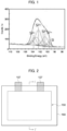
- FIG. 1 is a graph of Si2p spectrum obtained by an XPS analysis on silicon oxide particles according to example embodiments.
- a Si2p spectrum graph of the core portion and/or the surface portion of the silicon oxide particle may be obtained through the XPS.
- the obtained Si2p spectrum may be separated into peak regions representing Si 0 , Si 1+ , Si 2+ , Si 3+ and Si 4+ , respectively, by a deconvolution.
- the Si 0 peak region may correspond to a region of a binding energy from 98 eV to 100 eV
- the Si 1+ peak region may correspond to a region of a binding energy from 100 eV to 101 eV
- the Si 2+ peak region may correspond to a region of a binding energy from 101 eV to 102 eV
- the Si 3+ peak region may correspond to a region of a binding energy from 102 eV to 103 eV
- the Si 4+ peak region may correspond to a region of a binding energy from 103 eV to 106 eV.
- the number of silicon atoms and the number of oxygen atoms in each peak region can be calculated through the obtained peak areas of Si 0 , Si 1+ , Si 2+ , Si 3+ and Si 4+ .
- the oxidation number of the silicon oxide at the surface portion and/or the core portion may be obtained through the calculated total number of the silicon atoms and the total number of the oxygen atoms.
- the silicon oxide particle may be assumed to have silicon elements distributed in a Si-O matrix structure.
- the oxidation number (O S ) of the silicon oxide of the surface portion may be calculated by Equation 2 below.
- O S B + 2C + 3D + 4E / 5A + 4B + 3C + 2D + E
- A represents a peak area in a region from 98 eV to 100 eV measured by deconvolution of the Si2p spectrum of the surface portion obtained through the XPS analysis.
- B represents a peak area in a region from 100 eV to 101 eV measured by deconvolution of the Si2p spectrum of the surface portion obtained through the XPS analysis.
- C represents a peak area in a region from 101 eV to 102 eV measured by deconvolution of the Si2p spectrum of the surface portion obtained through the XPS analysis.
- D represents a peak area in a region from 102 eV to 103 eV measured by deconvolution of the Si2p spectrum of the surface portion obtained through the XPS analysis.
- E represents a peak area in a region from 103 eV to 106 eV measured by deconvolution of the Si2p spectrum of the surface portion obtained through the XPS analysis.
- the oxidation number (O C ) of the silicon oxide of the core portion may be calculated through Equation 3 below.
- O C G + 2 H + 3 I + 4 J / 5 F + 4 G + 3 H + 2I + J
- F represents a peak area in a region from 98 eV to 100 eV measured by deconvolution of the Si2p spectrum of the core portion obtained through the XPS analysis.
- G represents a peak area in a region from 100 eV to 101 eV measured by deconvolution of the Si2p spectrum of the core portion obtained through XPS analysis.
- H represents a peak area in a region from 101 eV to 102 eV measured by deconvolution of the Si2p spectrum of the core portion obtained through XPS analysis.
- I represents a peak area in a region from 102 eV to 103 eV measured by deconvolution of the Si2p spectrum of the core portion obtained through XPS analysis.
- J represents a peak area in a region from 103 eV to 106 eV measured by deconvolution of the Si2p spectrum of the core portion obtained through XPS analysis.
- the oxidation numbers of the silicon oxide included in the core portion or the surface portion may be different from each other.
- the oxidation numbers of each of the silicon oxides included in the core portion and the surface portion of the single silicon oxide particle can be obtained through Equations 2 and 3 above. Accordingly, a degree of oxidation of the silicon oxide according to the position in the silicon oxide particle may be evaluated and controlled.
- O C may be calculated from data obtained by etching to a depth of 300 nm or more from the surface of the silicon oxide particle using an argon ion gun of the XPS analysis.
- the etching may be performed 20 times under conditions of 4000 eV of ion energy, Ar monatomic mode and 300 seconds per time of etching cycle to etch to a depth of 300 nm or more.
- the Si2p spectrum graph may be obtained and the above-described peak areas may be measured by the deconvolution of the graph.
- O C may be 0.8 or more, and may be in a range from 0.8 to 1.0 in an embodiment.
- the SiO 2 matrix may be sufficiently formed at the inside of the silicon oxide particle (e.g., the core portion) to suppress expansion of the silicon oxide particle during charging and discharging.
- the capacity retention of the lithium secondary battery may be improved.
- a silicon oxide particle may be formed by mixing and firing a silicon source.
- the silicon source may include at least one selected from the group consisting of silicon and silicon dioxide (SiO 2 ).
- SiO 2 silicon dioxide
- a mixture of silicon and silicon dioxide may be used as the silicon source.
- the silicon source may be mixed, introduced into a reactor, and calcined at a temperature from about 1200 °C to 1600° C in a vacuum atmosphere.
- the calcined mixture of the silicon source may be deposited on a cooling plate and cooled.
- a temperature of the cooling plate may be FROM about 700 °C to 900 °C.
- the cooled silicon source mixture may be pulverized ground and classified to form the silicon oxide particles.
- the oxidation number ratio of the silicon oxide particle may be adjusted by controlling the calcination temperature of the reactor and/or the temperature of the cooling plate.
- a plurality of the silicon oxide particles may be formed by changing the calcination temperature of the reactor and the temperature of the cooling plate, and particles having the oxidation number ratio of 1.7 or more and less than 2.2 may be selected and used as the anode active material among the formed silicon oxide particles,
- the prepared silicon oxide particle and a carbon source gas may be mixed and fired to form a carbon coating on at least a portion of a surface of the silicon oxide particle
- the carbon source gas may be a mixed gas of a methane gas and an argon gas.
- the methane gas may be replaced with an ethylene gas, a propylene gas or an acetylene gas, or may be used together with the ethylene gas, the propylene gas or the acetylene gas.
- the carbon coating may be formed by a chemical vapor deposition (CVD).
- CVD chemical vapor deposition
- a carbon source gas may be injected to the silicon oxide particles while firing at a temperature from about 400 °C to 1200 °C to form the carbon coating.
- a heating rate during the firing may be in a range from 5 °C/min to 20 °C/min, and a firing time may be in a range from 60 minutes to 360 minutes.
- FIGS. 2 and 3 are a schematic plan view and a schematic cross-sectional view illustrating a secondary battery in accordance with exemplary embodiments.
- FIG. 3 is a cross-sectional view taken along a line I-I' of FIG. 2 in a thickness direction.
- the lithium secondary battery includes a cathode 100 and an anode 130 facing the cathode 100 and including the anode active material as described above.
- the cathode 100 may include a cathode current collector 105 and a cathode active material layer 110 disposed on at least one surface of the cathode current collector 105.
- the cathode current collector 105 may include stainless steel, nickel, aluminum, titanium, or an alloy thereof.
- the cathode current collector 105 may include aluminum or stainless steel surface-treated with carbon, nickel, titanium or silver.
- a thickness of the cathode current collector 105 may be in a range from 10 ⁇ m to 50 ⁇ m.
- the cathode active material layer 110 may include a cathode active material.
- the cathode active material may include a compound capable of reversibly intercalating and de-intercalating lithium ions.
- the cathode active material may include a lithium-nickel metal oxide.
- the lithium-nickel metal oxide may further include at least one of cobalt (Co), manganese (Mn) and aluminum (Al).
- the cathode active material or the lithium-nickel metal oxide may include a layered structure or a crystal structure represented by Chemical Formula 1 below. [Chemical Formula 1] Li x Ni a M b O 2+z
- M may include Co, Mn and/or Al.
- the chemical structure represented by Chemical Formula 1 indicates a bonding relationship included in the layered structure or the crystal structure of the cathode active material, and is not intended to exclude another additional element.
- M includes Co and/or Mn, and Co and/or Mn may serve as main active elements of the cathode active material together with Ni.
- Chemical Formula 1 is provided to express the bonding relationship of the main active elements, and is to be understood as a formula encompassing introduction and substitution of the additional element.
- an auxiliary element for enhancing chemical stability of the cathode active material or the layered structure/crystal structure may be further included in addition to the main active element.
- the auxiliary element may be incorporated into the layered structure/crystal structure to form a bond, and it is to be understood that this case is also included within the chemical structure represented by Chemical Formula 1.
- the auxiliary element may include at least one of, e.g., Na, Mg, Ca, Y, Ti, Hf, V, Nb, Ta, Cr, Mo, W, Fe, Cu, Ag, Zn, B, Al, Ga, C, Si, Sn, Sr, Ba, Ra, P and Zr.
- the auxiliary element may act as an auxiliary active element such as Al which may contribute to capacity/power activity of the cathode active material together with Co or Mn,
- the cathode active material or the lithium-nickel metal oxide may have a layered structure or a crystal structure represented by Chemical Formula 1-1 below.
- Chemical Formula 1-1 Li x Ni a M1 b1 M2 b2 O 2+z
- M1 may include Co, Mn and/or Al.
- M2 may include the above-described auxiliary element.
- the cathode active material may further include a coating element or a doping element.
- a coating element or a doping element for example, an element substantially the same as or similar to the above-mentioned auxiliary element may be used as the coating element or the doping element.
- one of the above elements or a combination of two or more therefrom may be used as the coating element or the doping element.
- the coating element or the doping element may be present on a surface of the lithium-nickel metal oxide particle or may penetrate through the surface of the lithium-nickel metal oxide particle and be included in the bonding structure represented by Chemical Formula 1 or Chemical Formula 1-1..
- the cathode active material may include a nickel-cobalt-manganese (NCM)-based lithium oxide.
- NCM nickel-cobalt-manganese
- an NCM-based lithium oxide having an increased nickel content may be used.
- Ni may serve as a transition metal related to power and capacity of a lithium secondary battery. Therefore, as described above, a high-Ni composition may be employed for the cathode active material, so that a high-capacity cathode and a high-capacity lithium secondary battery may be implemented.
- life-span stability and capacity retention may be improved by Mn while maintaining electrical conductivity by the inclusion of Co.
- a Ni content (e.g., A mole fraction of nickel among total moles of nickel, cobalt and manganese) in the NCM-based lithium oxide may be 0.6 or more, 0.7 or more, or 0.8 or more. In some embodiments, the Ni content may be from 0.8 to 0.95, from 0.82 to 0.95, from 0.83 to 0.95, from 0.84 to 0.95, from 0.85 to 0.95, or from 0.88 to 0.95.
- the cathode active material may include a lithium cobalt oxide-based active material, a lithium manganese oxide-based active material, a lithium nickel oxide-based active material, or a lithium iron phosphate (LFP) active material (e.g., LiFePO 4 ).
- the cathode active material may include a Li-rich layered oxide (LLO)/an over lithiated oxide (OLO)-based active material, a Mn-rich-based active material, a Co-less active materials, etc., having, e.g., a chemical structure or a crystal structure represented by Chemical Formula 2. These may be used alone or in a combination thereof [Chemical Formula 2] p[Li 2 MnO 3 ] ⁇ (1-p)[Li q JO 2 ]
- J includes at least one element selected from Mn, Ni, Co, Fe, Cr, V, Cu, Zn, Ti, Al, Mg and B.
- a cathode slurry may be prepared by mixing the cathode active material in a solvent.
- the cathode slurry may be coated on at least one surface of the cathode current collector 105, and dried and pressed to form the cathode active material layer 110.
- the coating method may include a gravure coating, a slot die coating, a multi-layer simultaneous die coating, an imprinting coating, a doctor blade coating, a dip coating, a bar coating, a casting, etc.
- the cathode active material layer 110 may further include a binder, and may optionally further include a conductive material, a thickener, etc.
- a non-aqueous solvent may be used as the solvent.
- NMP N-methyl-2-pyrrolidone
- dimethylformamide dimethylformamide
- dimethylacetamide dimethylacetamide
- N,N-dimethylaminopropylamine ethylene oxide
- tetrahydrofuran etc.
- the binder may include an organic based binder such as polyvinylidenefluoride (PVDF), a vinylidene fluoride-hexafluoropropylene copolymer, polyacrylonitrile, polymethylmethacrylate, acrylonitrile butadiene rubber (NBR), polybutadiene rubber (BR), styrene-butadiene rubber (SBR), etc. These may be used alone or in a combination thereof.
- PVDF polyvinylidenefluoride
- NBR acrylonitrile butadiene rubber
- BR polybutadiene rubber
- SBR styrene-butadiene rubber
- a PVDF-based binder may be used as a cathode binder.
- an amount of the binder for forming the cathode active material layer may be reduced, and an amount of the cathode active material may be relatively increased.
- capacity and power of the lithium secondary battery may be further improved.
- the conductive material may be included to promote an electron movement between active material particles.
- the conductive material may include a carbon-based conductive material such as graphite, carbon black, acetylene black, ketjen black, carbon fiber (such as carbon nanotube, vapor-grown carbon fiber (VGCF)), etc., and/or a metal-based conductive material including tin, tin oxide, titanium oxide, a perovskite material such as LaSrCoO 3 and LaSrMnO 3 , etc. These may be used alone or in a combination thereof.
- the cathode slurry may further include a thickener and/or a dispersive agent.
- the cathode slurry may include the thickener such as carboxymethyl cellulose (CMC).
- the anode 130 may include an anode current collector 125 and an anode active material layer 120 formed on at least one surface of the anode current collector 125.
- the anode current collector 125 may include a copper foil, a nickel foil, a stainless steel foil, a titanium foil, a nickel foam, a copper foam, or a polymer substrate coated with a conductive metal. These may be used alone or in a combination thereof.
- a thickness of the anode current collector 125 may be in a range from 10 ⁇ m to 50 ⁇ m.
- the anode active material layer 120 may include the anode active material including the above-described the silicon oxide particle.
- the anode active material may include a plurality of the silicon oxide particles.
- the anode active material may further include a graphite-based active material.
- the graphite-based active material may include artificial graphite and/or natural graphite.
- a content of the graphite-based active material based on a total weight of the silicon oxide particles and the graphite-based active material may be in a range from 0 wt % to 97 wt %.
- a content of the silicon oxide particles in a total weight of the anode active material may be 3 wt% or more, 5 wt% or more, 10 wt% or more, 15 wt% or more, 20 wt% or more, 25 wt% or more, 30 wt% or more, 35 wt% or more, 40 wt% or more, or 45% by weight or more.
- the content of the silicon oxide particle based on the total weight of the anode active material may be 90 wt% or less, 85 wt% or less, 80 wt% or less, 75 wt% or less, 70 wt% or less, 65 wt% or less, 60 wt% or less, 55 wt% or less % or less, or 50 wt% or less.
- the anode active material may substantially consist of the silicon oxide particles and the graphite-based active material.
- An anode slurry may be prepared by mixing the anode active material in a solvent.
- the anode slurry may be coated/deposited on the anode current collector 125, and then dried and pressed to form the anode active material layer 120.
- the coating method may include a gravure coating, a slot die coating, a multi-layer simultaneous die coating, an imprinting coating, a doctor blade coating, a dip coating, a bar coating, a casting, etc.
- the anode active material layer 120 may further include a binder, and may optionally further include a conductive material, a thickener, etc.
- the solvent included in the anode slurry may include water (such as pure water, deionized water, distilled water), ethanol, isopropanol, methanol, acetone, n-propanol, t-butanol, etc. These may be used alone or in a combination thereof.
- the above-described materials that may be used in the fabrication of the cathode 100 may be used as the binder, the conductive material and the thickener.
- a styrene-butadiene-rubber (SBR)-based binder may be used. These may be used alone or in a combination thereof.
- SBR styrene-butadiene-rubber
- CMC carboxymethyl cellulose
- PEDOT polyethylenedioxythiophene
- a separator 140 may be interposed between the anode 100 and the cathode 130. An ion flow may be generated through the separator 140 while preventing an electrical short between the anode 100 and the cathode 130.
- the separator 140 may have a thickness of 10 ⁇ m to 20 ⁇ m.
- the separator 140 may include a porous polymer film or a porous nonwoven fabric.
- the porous polymer film may include a polyolefin-based polymer such as an ethylene polymer, a propylene polymer, an ethylene/butene copolymer, an ethylene/hexene copolymer, an ethylene/methacrylate copolymer, etc. These may be used alone or in a combination thereof.
- a polyolefin-based polymer such as an ethylene polymer, a propylene polymer, an ethylene/butene copolymer, an ethylene/hexene copolymer, an ethylene/methacrylate copolymer, etc.
- the porous nonwoven fabric may include a glass fiber with a high melting point, a polyethylene terephthalate fiber, etc.
- the separator 140 may also include a ceramic-based material.
- inorganic particles may be coated on the polymer film or dispersed in the polymer film to improve heat resistance.
- the separator 140 may have a single-layered or multi-layered structure including the above-described polymer film and/or the nonwoven fabric.
- an electrode cell may be defined by the cathode 100, the anode 130 and the separator 140, and a plurality of the electrode cells may be stacked to form an electrode assembly 150 having, e.g., a jellyroll shape.
- the electrode assembly 150 may be formed by winding, stacking, z-folding and stack-folding of the separator 140.
- the electrode assembly 150 may be accommodated in a case 160 together with an electrolyte to define a lithium secondary battery.
- a non-aqueous electrolyte may be used as the electrolyte.
- the non-aqueous electrolyte may include a lithium salt and an organic solvent.
- the lithium salt and may be represented by Li + X - .
- An anion of the lithium salt X - may include, e.g., F - , Cl - , Br - , I - , NO 3 - , N(CN) 2 - , BF 4 - , ClO 4 - , PF 6 - , (CF 3 ) 2 PF 4 - , (CF 3 ) 3 PF 3 - , (CF 3 ) 4 PF 2 - , (CF 3 ) 5 PF - , (CF 3 ) 6 P-, CF 3 SO 3 - , CF 3 CF 2 SO 3 - , (CF 3 SO2) 2 N - , (FSO 2 ) 2 N - , CF 3 CF 2 (CF 3 ) 2 CO - , (CF 3 SO 2 ) 2 CH - , (SF 5
- the organic solvent may include, e.g., propylene carbonate (PC), ethylene carbonate (EC), butylene carbonate, diethyl carbonate (DEC), dimethyl carbonate (DMC), ethylmethyl carbonate (EMC), methylpropyl Carbonate, ethylpropyl carbonate, dipropyl carbonate, vinylene carbonate, methyl acetate (MA), ethyl acetate (EA), n-propylacetate (n-PA), 1,1-dimethyl ethyl acetate (DMEA), methyl propionate (MP), ethylpropionate (EP), fluoroethyl acetate (FEA), difluoroethyl acetate (DFEA), trifluoroethyl acetate (TFEA), dibutyl ether, tetraethylene glycol dimethyl ether (TEGDME), diethylene glycol dimethyl ether (DEGDME), dimethoxyethane
- the non-aqueous electrolyte may further include an additive.
- the additive may include, e.g., a cyclic carbonate-based compound, a fluorine-substituted carbonate-based compound, a sultone-based compound, a cyclic sulfate-based compound, a cyclic sulfite-based compound, a phosphate-based compound, a borate-based compound, etc. These may be used alone or in a combination thereof.
- the cyclic carbonate-based compound may include vinylene carbonate (VC), vinyl ethylene carbonate (VEC), etc.
- the fluorine-substituted cyclic carbonate-based compound may include fluoroethylene carbonate (FEC), etc.
- the sultone-based compound may include 1,3-propane sultone, 1,3-propene sultone, 1,4-butane sultone. etc.
- the cyclic sulfate-based compound may include 1,2-ethylene sulfate, 1,2-propylene sulfate, etc.
- the cyclic sulfite-based compound may include ethylene sulfite, butylene sulfite, etc.
- the phosphate-based compound may include lithium difluoro bis-oxalato phosphate, lithium difluoro phosphate, etc.
- the borate-based compound may include lithium bis(oxalate) borate, etc.
- a solid electrolyte may be used instead of the above-mentioned non-aqueous electrolyte.
- the lithium secondary battery may be manufactured in the form of an all-solid-state battery.
- a solid electrolyte layer may be disposed between the anode 100 and the cathode 130 instead of the above-described separator 140 as.
- the solid electrolyte may include a sulfide-based electrolyte.
- Non-limiting examples of the sulfide-based electrolyte may include Li 2 S-P 2 S 5 , Li 2 S-P 2 S 5 -LiCl, Li 2 S-P 2 S 5 -LiBr, Li 2 S-P 2 S 5 -LiCl-LiBr, Li 2 S-P 2 S 5 -Li2O, Li 2 S-P 2 S 5 -Li 2 O-LiI, Li 2 S-SiS 2 , Li 2 S-SiS 2 -LiI, Li 2 S-SiS 2 -LiBr, Li 2 S-SiS 2 -LiCl, Li 2 S-SiS 2 -B 2 S 3 -LiI, Li 2 S-SiS 2 -P 2 S 5 -LiI, Li 2 S-B 2 S 3 , Li 2 S-P 2 S 5 -Z m
- the solid electrolyte may include, e.g., an oxide-based amorphous solid electrolyte such as Li 2 O-B 2 O 3 -P 2 O 5 , Li 2 O-SiO 2 , Li 2 O-B 2 O 3 , Li 2 O-B 2 O 3 -ZnO, etc.
- an oxide-based amorphous solid electrolyte such as Li 2 O-B 2 O 3 -P 2 O 5 , Li 2 O-SiO 2 , Li 2 O-B 2 O 3 , Li 2 O-B 2 O 3 -ZnO, etc.
- electrode tabs may protrude from the cathode current collector 105 and the anode electrode current collector 125 included in each electrode cell to one side of the case 160.
- the electrode tabs may be welded together with the one side of the case 160 to form an electrode lead (a cathode lead 107 and an anode lead 127) extending or exposed to an outside of the case 160.
- the lithium secondary battery may be manufactured in, e.g., a cylindrical shape using a can, a square shape, a pouch shape or a coin shape.
- a mixture of silicon (Si) and silicon dioxide (SiO 2 ) as a raw material was put into a reactor at a weight ratio of 1:1, and fired for 5 hours under a vacuum atmosphere of 10 Pa. During the firing, a temperature of the reactor was maintained at 1400 °C.
- the fired mixture was deposited on a cooling plate and cooled. A temperature of the cooling plate was maintained at 800 °C.
- the deposited material was taken out from the cooling plate and pulverized and classified by a ball mill to obtain silicon oxide particles having an average particle diameter (D50) of 6 ⁇ m.
- the prepared silicon oxide particles were placed in a CVD coater, and a mixed gas of a methane gas and an argon gas was injected at a flow rate of 50 mL/min to 100 mL/min.
- a temperature of the CVD coater was increased to 900 °C at a heating rate of 5 °C/min to 20 °C/min, and maintained at 900 °C for about 60 minutes to 360 minutes to form a carbon coating on at least a portion of a surface of the silicon oxide particles.
- the surface of the silicon oxide was the outermost surface of the silicon oxide.
- the silicon oxide particles having the carbon coating formed thereon were used as an anode active material.
- the anode slurry was coated on a copper substrate, dried and pressed to fabricate an anode.
- a lithium secondary battery including the prepared anode and a Li metal as a counter electrode (cathode) was fabricated.
- a lithium coin half-cell was constructed by interposing a separator (polyethylene, thickness of 20 ⁇ m) between the prepared anode and the lithium metal (thickness of 1 mm).
- a separator polyethylene, thickness of 20 ⁇ m
- the assembly of the lithium metal/separator/anode was placed in a coin cell plate, an electrolyte solution was injected, and a cap was covered and clamped.
- the electrolyte solution was prepared by adding 2.0 vol% of FEC based on a total volume of the electrolyte solution to a 1.0M LiPF 6 solution using a mixed solvent of EC/EMC (30:70, volume ratio).
- An anode active material and a lithium secondary battery were prepared by the same method as that in Example 1, except that the temperature of the cooling plate was maintained at 825 °C.
- An anode active material and a lithium secondary battery were prepared by the same method as that in Example 1, except that the temperature of the cooling plate was maintained at 850 °C.
- An anode active material and a lithium secondary battery were prepared by the same method as that in Example 1, except that the temperature of the cooling plate was maintained at 875 °C.
- An anode active material and a lithium secondary battery were prepared by the same method as that in Example 1, except that the temperature of the cooling plate was maintained at 900 °C.
- An anode active material and a lithium secondary battery were prepared by the same method as that in Example 1, except that the temperature of the reactor was maintained at 1450 °C and the temperature of the cooling plate was maintained at 825 °C.
- An anode active material and a lithium secondary battery were prepared by the same method as that in Example 1, except that the temperature of the reactor was maintained at 1350 °C and the temperature of the cooling plate was maintained at 800 °C.
- An anode active material and a lithium secondary battery were prepared by the same method as that in Example 1, except that the temperature of the reactor was maintained at 1350 °C and the temperature of the cooling plate was maintained at 775 °C.
- An anode active material and a lithium secondary battery were prepared by the same method as that in Example 1, except that the temperature of the reactor was maintained at 1450 °C and the temperature of the cooling plate was maintained at 850 °C.
- the anode active material prepared according to each of Examples and Comparative Examples was attached on a carbon tape to prepare a sample, and an XPS analysis was performed under the following conditions to obtain a Si2p spectrum of a surface portion of the silicon oxide particle.
- a deconvolution of the obtained Si2p spectrum was performed, and a peak area in a region of 98 eV to 100 eV (A), a peak area in a region of 100 eV to 101 eV (B), a peak area in a region of 101 eV to 102 eV (C) , a peak area in a region of 102 eV to 103 eV (D), and a peak area in a region of 103 eV to 106 eV (E) were measured.
- the measured each peak area was substituted into Equation 2 as described above to obtain an oxidation number (O S ) of silicon oxide on a surface portion of the silicon oxide particle.
- the anode active material prepared according to each of Examples and Comparative Examples was attached on a carbon tape to form a sample, and an XPS analysis was performed under the following conditions to obtain a Si2p spectrum of a core portion of the silicon oxide particle.
- the surface of the silicon oxide particle according to each of Examples and Comparative Examples was etched 20 times for 300 seconds (total 6000 seconds) under the above conditions, and a Si2p spectrum in a region (core portion) where the shortest distance from the particle surface was 300 nm or more was obtained.
- a deconvolution of the obtained Si2p spectrum was performed, and a peak area in a region of 98 eV to 100 eV (F), a peak area in a region of 100 eV to 101 eV (G), a peak area in a region of 101 eV to 102 eV (H), a peak area in a region of 102 eV to 103 eV (I), and a peak area in a region of 103 eV to 106 eV (J) were measured.
- the measured each peak area was substituted into Equation 3 as described above to obtain an oxidation number (Oc) of silicon oxide from a core portion of the silicon oxide particle.
- the oxidation number ratio defined by Equation 1 was calculated by dividing the obtained O S by O C .
- the initial efficiency was evaluated as a percentage by dividing the measured initial charge capacity by the measured initial discharge capacity.
- An anode thickness (expanded anode thickness) immediately after charging (CC-CV 0.1C 0.01V 0.05C CUT-OFF) was performed at room temperature (25 ° C) for the lithium secondary battery manufactured according to each of Examples and Comparative Examples was measured.
- the thickness of the anode was measured by Micrometer MDC-MX of Mitutoyo company.
- the electrode expansion ratio was calculated by substituting the measured initial anode thickness and the expanded anode thickness into the following equation.
- Electrode expansion ratio (%) ⁇ (expanded anode thickness - initial anode thickness)/(initial anode thickness) ⁇ *100
- the capacity retention was evaluated as a percentage of a discharge capacity at the 50th cycle relative to a discharge capacity at the 1st cycle.
- Example 1 1724 1340 77.7 24.4 98.5
- Example 2 1780 1367 76.8 26.4 99.2
- Example 3 1824 1421 77.9 25.2 99.4
- Example 4 1856 1425 76.8 24.1 99.5
- Example 5 2178 1616 74.2 39.6 96.1
- Example 6 1788 1377 77.0 25.3 99.1
- Example 7 1766 1372 77.7 24.8 99.0
- Comparative Example 1 1690 1315 77.8 40.7 95.2 Comparative Example 2 2001 1419 70.9 28.5 98.3
- Example 5 where the oxidation number (O C ) of the silicon oxide in the core portion was less than 0.8, the initial efficiency and the capacity retention were relatively reduced.
- Comparative Example 1 where the oxidation number ratio was less than 1.7, the SiO 2 matrix was not sufficiently formed in the core portion of the silicon oxide particle. Accordingly, the electrode expansion ratio increased and the capacity retention was explicitly decreased.
Landscapes
- Chemical & Material Sciences (AREA)
- Chemical Kinetics & Catalysis (AREA)
- Electrochemistry (AREA)
- General Chemical & Material Sciences (AREA)
- Engineering & Computer Science (AREA)
- Inorganic Chemistry (AREA)
- Composite Materials (AREA)
- Materials Engineering (AREA)
- Manufacturing & Machinery (AREA)
- Organic Chemistry (AREA)
- Battery Electrode And Active Subsutance (AREA)
Abstract
An anode active material for a secondary battery according to an embodiment of the present invention includes a silicon oxide particle. The silicon oxide particle has a core portion and a surface portion on the core portion, and an oxidation number ratio defined as O<sub>S</sub>/O<sub>C</sub> of the silicon oxide particle is 1.7 or more, and less than 2.2. O<sub>S</sub> is an oxidation number of silicon oxide at the surface portion obtained by an X-ray photoelectron spectroscopy (XPS) analysis, and O<sub>C</sub> is an oxidation number of silicon oxide at the core portion obtained by the XPS analysis.
Description
- The disclosure of this patent application relates to an anode active material for a lithium secondary battery and a lithium secondary battery including the same.
- A secondary battery which can be charged and discharged repeatedly has been widely employed as a power source of a mobile electronic device such as a camcorder, a mobile phone, a laptop computer, etc., according to developments of information and display technologies. Recently, a battery pack including the secondary battery has been developed and applied as a power source for an eco-friendly vehicle such as an electric vehicle.
- Examples of the secondary battery includes, e.g., a lithium secondary battery, a nickel-cadmium battery, a nickel-hydrogen battery, etc. The lithium secondary battery is being widely developed and applied due to high operational voltage and energy density per unit weight, a high charging rate, a compact dimension, etc.
- For example, the lithium secondary battery may include an electrode assembly including a cathode, an anode and a separation layer (separator), and an electrolyte immersing the electrode assembly. The lithium secondary battery may further include an outer case having, e.g., a pouch shape for accommodating the electrode assembly and the electrolyte.
- Recently, as an application range of the lithium secondary battery is expanded, the lithium secondary battery having higher capacity and power has been researched. For example, silicon-based particles having with high capacity may be used for an anode active material. However, the silicon-based particles have relatively low stability and life-span properties of the secondary battery may be relatively degraded.
- According to an aspect of the present disclosure, there is provided an anode active material for a lithium secondary battery having improved power property and life-span property.
- According to an aspect of the present invention, there is provided a lithium secondary battery including an anode active material for a lithium secondary battery with improved power property and life-span property.
- An anode active material for a lithium secondary battery includes a silicon oxide particle. The silicon oxide particle has a core portion and a surface portion formed on the core portion, and an oxidation number ratio defined by Equation 1 of the silicon oxide particle is 1.7 or more, and less than 2.2,
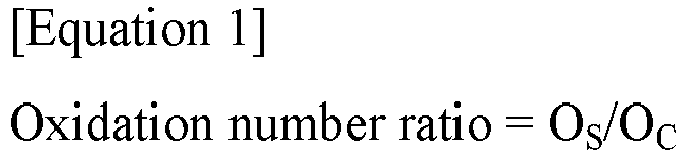
- In Equation 1, OS is an oxidation number of silicon oxide at the surface portion obtained by an X-ray photoelectron spectroscopy (XPS) analysis, and OC is an oxidation number of silicon oxide at the core portion obtained by the XPS analysis.
- In some embodiments, OS may be calculated by Equation 2.

- In Equation 2, A represents a peak area in a region from 98 eV to 100 eV measured by deconvolution of a Si2p spectrum of the surface portion obtained through the XPS analysis, B represents a peak area in a region from 100 eV to 101 eV measured by deconvolution of the Si2p spectrum of the surface portion obtained through the XPS analysis, C represents a peak area in a region from 101 eV to 102 eV measured by deconvolution of the Si2p spectrum of the surface portion obtained through the XPS analysis, D represents a peak area in a region from 102 eV to 103 eV measured by deconvolution of the Si2p spectrum of the surface portion obtained through the XPS analysis, and E represents a peak area in a region from 103 eV to 106 eV measured by deconvolution of the Si2p spectrum of the surface portion obtained through the XPS analysis.
- In some embodiments, Oc may be calculated by Equation 3.

- In Equation 3, F represents a peak area in a region from 98 eV to 100 eV measured by deconvolution of a Si2p spectrum of the core portion obtained through the XPS analysis, G represents a peak area in a region from 100 eV to 101 eV measured by deconvolution of the Si2p spectrum of the core portion obtained through XPS analysis, H represents a peak area in a region from 101 eV to 102 eV measured by deconvolution of the Si2p spectrum of the core portion obtained through XPS analysis, I represents a peak area in a region from 102 eV to 103 eV measured by deconvolution of the Si2p spectrum of the core portion obtained through XPS analysis, and J represents a peak area in a region from 103 eV to 106 eV measured by deconvolution of the Si2p spectrum of the core portion obtained through XPS analysis.
- In some embodiments, a shortest distance from a surface of the silicon oxide particle to an outer surface of the core portion may be 300 nm or more.
- In some embodiments, OC may be 0.8 or more.
- In some embodiments, OC may be in a range from 0.8 to 1.0.
- In some embodiments, the silicon oxide particle may include SiOx (0<x≤2).
- In some embodiments, a carbon coating may be formed on at least a portion of a surface of the silicon oxide particle.
- In some embodiments, the silicon oxide particle may be doped with at least one metal selected from the group consisting of Li, Mg, Al, Ca, Fe, Ti and V.
- A lithium secondary battery includes an anode including the anode active material for a lithium secondary battery according to the above-described embodiments, and a cathode facing the anode.
- In some embodiments, the anode may further include a graphite-based active material.
- In some embodiments, the graphite-based active material may include at least one selected from the group consisting of artificial graphite and natural graphite.
- According to an embodiment of the present disclosure, expansion of silicon oxide particles may be suppressed while facilitating movement of lithium ions during charging and discharging. Accordingly, both power and life-span properties may be improved.
- According to an embodiment of the present disclosure, a SiO2 matrix may be sufficiently formed at an inside of the silicon oxide particles (e.g., in a core portion), so that expansion of the silicon oxide particles during charging and discharging may be suppressed. Accordingly, a capacity retention of the lithium secondary battery may be improved.
- The anode active material and the lithium secondary battery according to the present disclosure can be widely applied in green technology fields such as an electric vehicle, a battery charging station, a solar power generation/wind power generation using the battery. The anode active material and the lithium secondary battery according to the present disclosure may be used in eco-friendly electric vehicles and hybrid vehicles for preventing a climate change by suppressing air pollution and greenhouse gas emissions.
-
-
FIG. 1 is a graph of Si2p spectrum obtained by an X-ray photoelectron spectroscopy (XPS) analysis on silicon oxide particles according to example embodiments. -
FIGS. 2 and3 are a schematic plan view and a schematic cross-sectional view illustrating a secondary battery in accordance with exemplary embodiments, respectively. - According to embodiments of the present disclosure, an anode active material for a lithium secondary battery including a silicon oxide particle. Further, a lithium secondary battery including the anode active material is provided.
- Hereinafter, detailed descriptions of the present disclosure will be described in detail with reference to exemplary embodiments. However, those skilled in the art will appreciate that such embodiments are provided to further understand the spirit of the present invention and do not limit subject matters to be protected as disclosed in the detailed description and appended claims.
- An anode active material for a lithium secondary battery (hereinafter, that may be abbreviated as "an anode active material") includes a silicon oxide particle. A plurality of the silicon oxide particles may be included in the anode active material.
- The silicon oxide particle includes a core portion and a surface portion formed on the core portion.
- For example, a shortest distance from the surface of the silicon oxide particle to an outer surface of the core portion may be 300 nm or more.
- For example, the surface portion may be integrally formed with the core portion, and may be formed to surround the core portion. For example, a thickness of the surface portion may be less than 300 nm.
- In some embodiments, the silicon oxide particle may include SiOx (0<x≤2).
- For example, the silicon oxide particle may include a form in which silicon particles are distributed in a SiO2 matrix. Accordingly, particle expansion may be alleviated by the SiO2 matrix, so that life-span properties may be improved while enhancing capacity properties by the silicon particles.
- In some embodiments, the silicon oxide particle may be doped with an auxiliary element to reduce a resistance and improve power properties.
- For example, the auxiliary element doped into the silicon oxide particle may include at least one metal selected from the group consisting of Li, Mg, Al, Ca, Fe, Ti and V.
- In an embodiment, the auxiliary element may include Li or Mg.
- An oxidation number ratio defined by Equation 1 below of the silicon oxide particle is 1.7 or more, and less than 2.2,
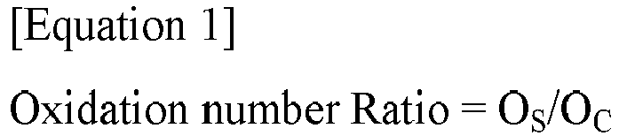
- In Equation 1, OS is an oxidation number of silicon oxide at the surface portion obtained through an X-ray photoelectron spectroscopy (XPS) analysis, and OC is an oxidation number of silicon oxide at the core portion obtained through XPS analysis.
- As used herein, the terms "oxidation number of silicon oxide" and/or "oxidation number" may represent a ratio of the number of moles of an oxygen element to the number of moles of a silicon element in the core portion or the surface portion of the silicon oxide particle obtained by the XPS.
- For example, OS may be a ratio of the number of moles of the oxygen element to the number of moles of the silicon element obtained through the XPS of the surface portion. For example, OS may be a z value when a silicon oxide composition of the surface portion is SiOz.
- For example, Oc may be a ratio of the number of moles of the oxygen element to the number of moles of the silicon element obtained through the XPS of the core portion. For example, Oc may be a y value when a silicon oxide composition of the core portion is SiOy.
- Within the oxidation number ratio range, movement of the lithium ions during charging and discharging may be facilitated while suppressing an expansion of the silicon oxide particle. Accordingly, power and life-span properties may be both improved.
- For example, if the oxidation number ratio is 2.2 or more, a thickness of an oxide layer of the surface portion may be increased to lower a mobility of the lithium ions. Accordingly, an initial efficiency of the lithium secondary battery may be decreased.
- For example, if the oxidation number ratio is less than 1.7, the SiO2 matrix may not be sufficiently formed in the core portion, and an anode swelling may be caused and the capacity retention of the lithium secondary battery may be decreased.
-
FIG. 1 is a graph of Si2p spectrum obtained by an XPS analysis on silicon oxide particles according to example embodiments. - Referring to
FIG. 1 , a Si2p spectrum graph of the core portion and/or the surface portion of the silicon oxide particle may be obtained through the XPS. - For example, the obtained Si2p spectrum may be separated into peak regions representing Si0, Si1+, Si2+, Si3+ and Si4+, respectively, by a deconvolution.
- For example, the Si0 peak region may correspond to a region of a binding energy from 98 eV to 100 eV, the Si1+ peak region may correspond to a region of a binding energy from 100 eV to 101 eV, the Si2+ peak region may correspond to a region of a binding energy from 101 eV to 102 eV, the Si3+ peak region may correspond to a region of a binding energy from 102 eV to 103 eV, and the Si4+ peak region may correspond to a region of a binding energy from 103 eV to 106 eV.
- The number of silicon atoms and the number of oxygen atoms in each peak region can be calculated through the obtained peak areas of Si0, Si1+, Si2+, Si3+ and Si4+. The oxidation number of the silicon oxide at the surface portion and/or the core portion may be obtained through the calculated total number of the silicon atoms and the total number of the oxygen atoms.
- For example, for the XPS analysis, the silicon oxide particle may be assumed to have silicon elements distributed in a Si-O matrix structure.
- In some embodiments, the oxidation number (OS) of the silicon oxide of the surface portion may be calculated by Equation 2 below.

- In Equation 2, A represents a peak area in a region from 98 eV to 100 eV measured by deconvolution of the Si2p spectrum of the surface portion obtained through the XPS analysis. B represents a peak area in a region from 100 eV to 101 eV measured by deconvolution of the Si2p spectrum of the surface portion obtained through the XPS analysis. C represents a peak area in a region from 101 eV to 102 eV measured by deconvolution of the Si2p spectrum of the surface portion obtained through the XPS analysis. D represents a peak area in a region from 102 eV to 103 eV measured by deconvolution of the Si2p spectrum of the surface portion obtained through the XPS analysis. E represents a peak area in a region from 103 eV to 106 eV measured by deconvolution of the Si2p spectrum of the surface portion obtained through the XPS analysis.
- In some embodiments, the oxidation number (OC) of the silicon oxide of the core portion may be calculated through Equation 3 below.

- In Equation 3, F represents a peak area in a region from 98 eV to 100 eV measured by deconvolution of the Si2p spectrum of the core portion obtained through the XPS analysis. G represents a peak area in a region from 100 eV to 101 eV measured by deconvolution of the Si2p spectrum of the core portion obtained through XPS analysis. H represents a peak area in a region from 101 eV to 102 eV measured by deconvolution of the Si2p spectrum of the core portion obtained through XPS analysis. I represents a peak area in a region from 102 eV to 103 eV measured by deconvolution of the Si2p spectrum of the core portion obtained through XPS analysis. J represents a peak area in a region from 103 eV to 106 eV measured by deconvolution of the Si2p spectrum of the core portion obtained through XPS analysis.
- For example, even though an average oxidation number of the entire silicon oxide particle is the same, the oxidation numbers of the silicon oxide included in the core portion or the surface portion may be different from each other. The oxidation numbers of each of the silicon oxides included in the core portion and the surface portion of the single silicon oxide particle can be obtained through Equations 2 and 3 above. Accordingly, a degree of oxidation of the silicon oxide according to the position in the silicon oxide particle may be evaluated and controlled.
- For example, OC may be calculated from data obtained by etching to a depth of 300 nm or more from the surface of the silicon oxide particle using an argon ion gun of the XPS analysis.
- For example, the etching may be performed 20 times under conditions of 4000 eV of ion energy, Ar monatomic mode and 300 seconds per time of etching cycle to etch to a depth of 300 nm or more.
- For example, after etching to a depth of 300 nm or more from the surface of the silicon oxide particle using the argon ion gun, the Si2p spectrum graph may be obtained and the above-described peak areas may be measured by the deconvolution of the graph.
- In some embodiments, OC may be 0.8 or more, and may be in a range from 0.8 to 1.0 in an embodiment. Within this range, the SiO2 matrix may be sufficiently formed at the inside of the silicon oxide particle (e.g., the core portion) to suppress expansion of the silicon oxide particle during charging and discharging. Thus, the capacity retention of the lithium secondary battery may be improved.
- Hereinafter, a preparation method of the anode active material for a lithium secondary battery as described above according to example embodiments is provided.
- In example embodiments, a silicon oxide particle may be formed by mixing and firing a silicon source.
- For example, the silicon source may include at least one selected from the group consisting of silicon and silicon dioxide (SiO2). In an embodiment, a mixture of silicon and silicon dioxide may be used as the silicon source.
- For example, the silicon source may be mixed, introduced into a reactor, and calcined at a temperature from about 1200 °C to 1600° C in a vacuum atmosphere.
- In example embodiments, the calcined mixture of the silicon source may be deposited on a cooling plate and cooled. A temperature of the cooling plate may be FROM about 700 °C to 900 °C.
- The cooled silicon source mixture may be pulverized ground and classified to form the silicon oxide particles.
- For example, the oxidation number ratio of the silicon oxide particle may be adjusted by controlling the calcination temperature of the reactor and/or the temperature of the cooling plate.
- For example, a plurality of the silicon oxide particles may be formed by changing the calcination temperature of the reactor and the temperature of the cooling plate, and particles having the oxidation number ratio of 1.7 or more and less than 2.2 may be selected and used as the anode active material among the formed silicon oxide particles,
- In some embodiments, the prepared silicon oxide particle and a carbon source gas may be mixed and fired to form a carbon coating on at least a portion of a surface of the silicon oxide particle
- For example, the carbon source gas may be a mixed gas of a methane gas and an argon gas.
- In some embodiments, the methane gas may be replaced with an ethylene gas, a propylene gas or an acetylene gas, or may be used together with the ethylene gas, the propylene gas or the acetylene gas.
- In some embodiments, the carbon coating may be formed by a chemical vapor deposition (CVD). For example, a carbon source gas may be injected to the silicon oxide particles while firing at a temperature from about 400 °C to 1200 °C to form the carbon coating. For example, a heating rate during the firing may be in a range from 5 °C/min to 20 °C/min, and a firing time may be in a range from 60 minutes to 360 minutes.
-
FIGS. 2 and3 are a schematic plan view and a schematic cross-sectional view illustrating a secondary battery in accordance with exemplary embodiments. For example,FIG. 3 is a cross-sectional view taken along a line I-I' ofFIG. 2 in a thickness direction. - Referring to
FIGS. 2 and3 , the lithium secondary battery includes acathode 100 and ananode 130 facing thecathode 100 and including the anode active material as described above. - For example, the
cathode 100 may include a cathodecurrent collector 105 and a cathodeactive material layer 110 disposed on at least one surface of the cathodecurrent collector 105. - The cathode
current collector 105 may include stainless steel, nickel, aluminum, titanium, or an alloy thereof. The cathodecurrent collector 105 may include aluminum or stainless steel surface-treated with carbon, nickel, titanium or silver. For example, a thickness of the cathodecurrent collector 105 may be in a range from 10 µm to 50 µm. - The cathode
active material layer 110 may include a cathode active material. The cathode active material may include a compound capable of reversibly intercalating and de-intercalating lithium ions. - In example embodiments, the cathode active material may include a lithium-nickel metal oxide. The lithium-nickel metal oxide may further include at least one of cobalt (Co), manganese (Mn) and aluminum (Al).
- In some embodiments, the cathode active material or the lithium-nickel metal oxide may include a layered structure or a crystal structure represented by Chemical Formula 1 below.
[Chemical Formula 1] LixNiaMbO2+z
- In Chemical Formula 1, 0.9≤x≤1.2, 0.6≤a≤0.99, 0.01≤b≤0.4 and -0.5≤z≤0.1. As mentioned above, M may include Co, Mn and/or Al.
- The chemical structure represented by Chemical Formula 1 indicates a bonding relationship included in the layered structure or the crystal structure of the cathode active material, and is not intended to exclude another additional element. For example, M includes Co and/or Mn, and Co and/or Mn may serve as main active elements of the cathode active material together with Ni. Chemical Formula 1 is provided to express the bonding relationship of the main active elements, and is to be understood as a formula encompassing introduction and substitution of the additional element.
- In an embodiment, an auxiliary element for enhancing chemical stability of the cathode active material or the layered structure/crystal structure may be further included in addition to the main active element. The auxiliary element may be incorporated into the layered structure/crystal structure to form a bond, and it is to be understood that this case is also included within the chemical structure represented by Chemical Formula 1.
- The auxiliary element may include at least one of, e.g., Na, Mg, Ca, Y, Ti, Hf, V, Nb, Ta, Cr, Mo, W, Fe, Cu, Ag, Zn, B, Al, Ga, C, Si, Sn, Sr, Ba, Ra, P and Zr. The auxiliary element may act as an auxiliary active element such as Al which may contribute to capacity/power activity of the cathode active material together with Co or Mn,
- For example, the cathode active material or the lithium-nickel metal oxide may have a layered structure or a crystal structure represented by Chemical Formula 1-1 below.
[Formula 1-1] LixNiaM1b1M2b2O2+z
- In Chemical Formula 1-1, M1 may include Co, Mn and/or Al. M2 may include the above-described auxiliary element. In Chemical Formula 1-1, 0.9≤x≤1.2, 0.6≤a≤0.99, 0.01≤b1+b2≤0.4, and -0.5≤z≤0.1.
- The cathode active material may further include a coating element or a doping element. For example, an element substantially the same as or similar to the above-mentioned auxiliary element may be used as the coating element or the doping element. For example, one of the above elements or a combination of two or more therefrom may be used as the coating element or the doping element.
- The coating element or the doping element may be present on a surface of the lithium-nickel metal oxide particle or may penetrate through the surface of the lithium-nickel metal oxide particle and be included in the bonding structure represented by Chemical Formula 1 or Chemical Formula 1-1..
- The cathode active material may include a nickel-cobalt-manganese (NCM)-based lithium oxide. In this case, an NCM-based lithium oxide having an increased nickel content may be used.
- Ni may serve as a transition metal related to power and capacity of a lithium secondary battery. Therefore, as described above, a high-Ni composition may be employed for the cathode active material, so that a high-capacity cathode and a high-capacity lithium secondary battery may be implemented.
- However, as the content of Ni increases, long-term storage stability and life-span stability of the cathode or the secondary battery may be relatively deteriorated, and side reactions with the electrolyte may be also increased. However, according to example embodiments, life-span stability and capacity retention may be improved by Mn while maintaining electrical conductivity by the inclusion of Co.
- A Ni content (e.g., A mole fraction of nickel among total moles of nickel, cobalt and manganese) in the NCM-based lithium oxide may be 0.6 or more, 0.7 or more, or 0.8 or more. In some embodiments, the Ni content may be from 0.8 to 0.95, from 0.82 to 0.95, from 0.83 to 0.95, from 0.84 to 0.95, from 0.85 to 0.95, or from 0.88 to 0.95.
- In some embodiments, the cathode active material may include a lithium cobalt oxide-based active material, a lithium manganese oxide-based active material, a lithium nickel oxide-based active material, or a lithium iron phosphate (LFP) active material (e.g., LiFePO4).
- In some embodiments, the cathode active material may include a Li-rich layered oxide (LLO)/an over lithiated oxide (OLO)-based active material, a Mn-rich-based active material, a Co-less active materials, etc., having, e.g., a chemical structure or a crystal structure represented by Chemical Formula 2. These may be used alone or in a combination thereof
[Chemical Formula 2] p[Li2MnO3]·(1-p)[LiqJO2]
- In Chemical Formula 2, 0<p<1, 0.9≤q≤1.2, and J includes at least one element selected from Mn, Ni, Co, Fe, Cr, V, Cu, Zn, Ti, Al, Mg and B.
- A cathode slurry may be prepared by mixing the cathode active material in a solvent. The cathode slurry may be coated on at least one surface of the cathode
current collector 105, and dried and pressed to form the cathodeactive material layer 110. The coating method may include a gravure coating, a slot die coating, a multi-layer simultaneous die coating, an imprinting coating, a doctor blade coating, a dip coating, a bar coating, a casting, etc. The cathodeactive material layer 110 may further include a binder, and may optionally further include a conductive material, a thickener, etc. - A non-aqueous solvent may be used as the solvent. For example, N-methyl-2-pyrrolidone (NMP), dimethylformamide, dimethylacetamide, N,N-dimethylaminopropylamine, ethylene oxide, tetrahydrofuran, etc., may be used as the solvent.
- For example, the binder may include an organic based binder such as polyvinylidenefluoride (PVDF), a vinylidene fluoride-hexafluoropropylene copolymer, polyacrylonitrile, polymethylmethacrylate, acrylonitrile butadiene rubber (NBR), polybutadiene rubber (BR), styrene-butadiene rubber (SBR), etc. These may be used alone or in a combination thereof.
- For example, a PVDF-based binder may be used as a cathode binder. In this case, an amount of the binder for forming the cathode active material layer may be reduced, and an amount of the cathode active material may be relatively increased. Thus, capacity and power of the lithium secondary battery may be further improved.
- The conductive material may be included to promote an electron movement between active material particles. For example, the conductive material may include a carbon-based conductive material such as graphite, carbon black, acetylene black, ketjen black, carbon fiber (such as carbon nanotube, vapor-grown carbon fiber (VGCF)), etc., and/or a metal-based conductive material including tin, tin oxide, titanium oxide, a perovskite material such as LaSrCoO3 and LaSrMnO3, etc. These may be used alone or in a combination thereof.
- The cathode slurry may further include a thickener and/or a dispersive agent. In an embodiment, the cathode slurry may include the thickener such as carboxymethyl cellulose (CMC).
- The
anode 130 may include an anodecurrent collector 125 and an anodeactive material layer 120 formed on at least one surface of the anodecurrent collector 125. - For example, the anode
current collector 125 may include a copper foil, a nickel foil, a stainless steel foil, a titanium foil, a nickel foam, a copper foam, or a polymer substrate coated with a conductive metal. These may be used alone or in a combination thereof. For example, a thickness of the anodecurrent collector 125 may be in a range from 10 µm to 50 µm. - The anode
active material layer 120 may include the anode active material including the above-described the silicon oxide particle. For example, the anode active material may include a plurality of the silicon oxide particles. - In some embodiments, the anode active material may further include a graphite-based active material. For example, the graphite-based active material may include artificial graphite and/or natural graphite.
- For example, a content of the graphite-based active material based on a total weight of the silicon oxide particles and the graphite-based active material may be in a range from 0 wt % to 97 wt %.
- A content of the silicon oxide particles in a total weight of the anode active material (e.g., the total weight of the silicon oxide particles and the graphite-based active material) may be 3 wt% or more, 5 wt% or more, 10 wt% or more, 15 wt% or more, 20 wt% or more, 25 wt% or more, 30 wt% or more, 35 wt% or more, 40 wt% or more, or 45% by weight or more.
- The content of the silicon oxide particle based on the total weight of the anode active material may be 90 wt% or less, 85 wt% or less, 80 wt% or less, 75 wt% or less, 70 wt% or less, 65 wt% or less, 60 wt% or less, 55 wt% or less % or less, or 50 wt% or less.
- In an embodiment, the anode active material may substantially consist of the silicon oxide particles and the graphite-based active material.
- An anode slurry may be prepared by mixing the anode active material in a solvent. The anode slurry may be coated/deposited on the anode
current collector 125, and then dried and pressed to form the anodeactive material layer 120. The coating method may include a gravure coating, a slot die coating, a multi-layer simultaneous die coating, an imprinting coating, a doctor blade coating, a dip coating, a bar coating, a casting, etc. The anodeactive material layer 120 may further include a binder, and may optionally further include a conductive material, a thickener, etc. - The solvent included in the anode slurry may include water (such as pure water, deionized water, distilled water), ethanol, isopropanol, methanol, acetone, n-propanol, t-butanol, etc. These may be used alone or in a combination thereof.
- The above-described materials that may be used in the fabrication of the
cathode 100 may be used as the binder, the conductive material and the thickener. - In some embodiments, a styrene-butadiene-rubber (SBR)-based binder, carboxymethyl cellulose (CMC), a polyacrylic acid-based binder, a polyethylenedioxythiophene (poly(3,4-ethylenedioxythiophene), PEDOT)-based binder, etc., may be used. These may be used alone or in a combination thereof.
- In some embodiments, a
separator 140 may be interposed between theanode 100 and thecathode 130. An ion flow may be generated through theseparator 140 while preventing an electrical short between theanode 100 and thecathode 130. For example, theseparator 140 may have a thickness of 10 µm to 20 µm. - For example, the
separator 140 may include a porous polymer film or a porous nonwoven fabric. - The porous polymer film may include a polyolefin-based polymer such as an ethylene polymer, a propylene polymer, an ethylene/butene copolymer, an ethylene/hexene copolymer, an ethylene/methacrylate copolymer, etc. These may be used alone or in a combination thereof.
- The porous nonwoven fabric may include a glass fiber with a high melting point, a polyethylene terephthalate fiber, etc.
- The
separator 140 may also include a ceramic-based material. For example, inorganic particles may be coated on the polymer film or dispersed in the polymer film to improve heat resistance. - The
separator 140 may have a single-layered or multi-layered structure including the above-described polymer film and/or the nonwoven fabric. - In example embodiments, an electrode cell may be defined by the
cathode 100, theanode 130 and theseparator 140, and a plurality of the electrode cells may be stacked to form anelectrode assembly 150 having, e.g., a jellyroll shape. For example, theelectrode assembly 150 may be formed by winding, stacking, z-folding and stack-folding of theseparator 140. - The
electrode assembly 150 may be accommodated in acase 160 together with an electrolyte to define a lithium secondary battery. In example embodiments, a non-aqueous electrolyte may be used as the electrolyte. - The non-aqueous electrolyte may include a lithium salt and an organic solvent. The lithium salt and may be represented by Li+X-. An anion of the lithium salt X- may include, e.g., F-, Cl-, Br-, I-, NO3 -, N(CN)2 -, BF4 -, ClO4 -, PF6 -, (CF3)2PF4 -, (CF3)3PF3 -, (CF3)4PF2 -, (CF3)5PF-, (CF3)6P-, CF3SO3 -, CF3CF2SO3 -, (CF3SO2)2N-, (FSO2)2N-, CF3CF2(CF3)2CO-, (CF3SO2)2CH-, (SF5)3C-, (CF3SO2)3C-, CF3(CF2)7SO3 -, CF3CO2 -, CH3CO2 -, SCN-, (CF3CF2SO2)2N-, etc.
- The organic solvent may include, e.g., propylene carbonate (PC), ethylene carbonate (EC), butylene carbonate, diethyl carbonate (DEC), dimethyl carbonate (DMC), ethylmethyl carbonate (EMC), methylpropyl Carbonate, ethylpropyl carbonate, dipropyl carbonate, vinylene carbonate, methyl acetate (MA), ethyl acetate (EA), n-propylacetate (n-PA), 1,1-dimethyl ethyl acetate (DMEA), methyl propionate (MP), ethylpropionate (EP), fluoroethyl acetate (FEA), difluoroethyl acetate (DFEA), trifluoroethyl acetate (TFEA), dibutyl ether, tetraethylene glycol dimethyl ether (TEGDME), diethylene glycol dimethyl ether (DEGDME), dimethoxyethane, tetrahydrofuran (THF), 2-methyltetrahydrofuran, ethyl alcohol, isopropyl alcohol, dimethylsulfoxide, acetonitrile, dimethoxyethane, diethoxyethane, sulfolane, gamma-butyrolactone, propylene sulfite, etc. These may be used alone or in a combination thereof.
- The non-aqueous electrolyte may further include an additive. The additive may include, e.g., a cyclic carbonate-based compound, a fluorine-substituted carbonate-based compound, a sultone-based compound, a cyclic sulfate-based compound, a cyclic sulfite-based compound, a phosphate-based compound, a borate-based compound, etc. These may be used alone or in a combination thereof.
- The cyclic carbonate-based compound may include vinylene carbonate (VC), vinyl ethylene carbonate (VEC), etc.
- The fluorine-substituted cyclic carbonate-based compound may include fluoroethylene carbonate (FEC), etc.
- The sultone-based compound may include 1,3-propane sultone, 1,3-propene sultone, 1,4-butane sultone. etc.
- The cyclic sulfate-based compound may include 1,2-ethylene sulfate, 1,2-propylene sulfate, etc.
- The cyclic sulfite-based compound may include ethylene sulfite, butylene sulfite, etc.
- The phosphate-based compound may include lithium difluoro bis-oxalato phosphate, lithium difluoro phosphate, etc.
- The borate-based compound may include lithium bis(oxalate) borate, etc.
- In some embodiments, a solid electrolyte may be used instead of the above-mentioned non-aqueous electrolyte. In this case, the lithium secondary battery may be manufactured in the form of an all-solid-state battery. Additionally, a solid electrolyte layer may be disposed between the
anode 100 and thecathode 130 instead of the above-describedseparator 140 as. - The solid electrolyte may include a sulfide-based electrolyte. Non-limiting examples of the sulfide-based electrolyte may include Li2S-P2S5, Li2S-P2S5-LiCl, Li2S-P2S5-LiBr, Li2S-P2S5-LiCl-LiBr, Li2S-P2S5-Li2O, Li2S-P2S5-Li2O-LiI, Li2S-SiS2, Li2S-SiS2-LiI, Li2S-SiS2-LiBr, Li2S-SiS2-LiCl, Li2S-SiS2-B2S3-LiI, Li2S-SiS2-P2S5-LiI, Li2S-B2S3, Li2S-P2S5-ZmSn (m and n are positive numbers, and Z represents Ge, Zn pr Ga), Li2S-GeS2, Li2S-SiS2-Li3PO4, Li2S-SiS2-LipMOq, (p and q are positive numbers, M represents P, Si, Ge, B, Al, Ga or In), Li7-xPS6-xClx (0≤x≤2), Li7-xPS6-xBrx (0≤x≤2), Li7-xPS6-xIx (0≤x≤2), etc. These may be used alone in a combination thereof.
- In an embodiment, the solid electrolyte may include, e.g., an oxide-based amorphous solid electrolyte such as Li2O-B2O3-P2O5, Li2O-SiO2, Li2O-B2O3, Li2O-B2O3-ZnO, etc.
- As illustrated in
FIGS. 2 and3 , electrode tabs (a cathode tab and an anode tab) may protrude from the cathodecurrent collector 105 and the anode electrodecurrent collector 125 included in each electrode cell to one side of thecase 160. The electrode tabs may be welded together with the one side of thecase 160 to form an electrode lead (acathode lead 107 and an anode lead 127) extending or exposed to an outside of thecase 160. - The lithium secondary battery may be manufactured in, e.g., a cylindrical shape using a can, a square shape, a pouch shape or a coin shape.
- Hereinafter, experimental examples are proposed to more concretely describe the present disclosure.
- A mixture of silicon (Si) and silicon dioxide (SiO2) as a raw material was put into a reactor at a weight ratio of 1:1, and fired for 5 hours under a vacuum atmosphere of 10 Pa. During the firing, a temperature of the reactor was maintained at 1400 °C.
- The fired mixture was deposited on a cooling plate and cooled. A temperature of the cooling plate was maintained at 800 °C.
- The deposited material was taken out from the cooling plate and pulverized and classified by a ball mill to obtain silicon oxide particles having an average particle diameter (D50) of 6 µm.
- The prepared silicon oxide particles were placed in a CVD coater, and a mixed gas of a methane gas and an argon gas was injected at a flow rate of 50 mL/min to 100 mL/min. A temperature of the CVD coater was increased to 900 °C at a heating rate of 5 °C/min to 20 °C/min, and maintained at 900 °C for about 60 minutes to 360 minutes to form a carbon coating on at least a portion of a surface of the silicon oxide particles. The surface of the silicon oxide was the outermost surface of the silicon oxide.
- The silicon oxide particles having the carbon coating formed thereon were used as an anode active material.
- 10 wt% of the prepared anode active material, 85.5 wt% of artificial graphite, 1 wt% of MWCNT as a conductive material, 2 wt% of styrene-butadiene rubber (SBR) as a binder and 1.5 wt% of carboxymethyl cellulose (CMC) as a thickener were mixed in pure water as a solvent to obtain an anode slurry.
- The anode slurry was coated on a copper substrate, dried and pressed to fabricate an anode.
- A lithium secondary battery including the prepared anode and a Li metal as a counter electrode (cathode) was fabricated.
- Specifically, a lithium coin half-cell was constructed by interposing a separator (polyethylene, thickness of 20 µm) between the prepared anode and the lithium metal (thickness of 1 mm).
- The assembly of the lithium metal/separator/anode was placed in a coin cell plate, an electrolyte solution was injected, and a cap was covered and clamped. The electrolyte solution was prepared by adding 2.0 vol% of FEC based on a total volume of the electrolyte solution to a 1.0M LiPF6 solution using a mixed solvent of EC/EMC (30:70, volume ratio).
- After impregnation for 3 hours to 24 hours after the clamping, a formation charging/discharging was performed (charging condition CC-CV 0.1C 0.01V 0.01C CUT-OFF, discharging condition CC 0.1C 1.5V CUT-OFF).
- An anode active material and a lithium secondary battery were prepared by the same method as that in Example 1, except that the temperature of the cooling plate was maintained at 825 °C.
- An anode active material and a lithium secondary battery were prepared by the same method as that in Example 1, except that the temperature of the cooling plate was maintained at 850 °C.
- An anode active material and a lithium secondary battery were prepared by the same method as that in Example 1, except that the temperature of the cooling plate was maintained at 875 °C.
- An anode active material and a lithium secondary battery were prepared by the same method as that in Example 1, except that the temperature of the cooling plate was maintained at 900 °C.
- An anode active material and a lithium secondary battery were prepared by the same method as that in Example 1, except that the temperature of the reactor was maintained at 1450 °C and the temperature of the cooling plate was maintained at 825 °C.
- An anode active material and a lithium secondary battery were prepared by the same method as that in Example 1, except that the temperature of the reactor was maintained at 1350 °C and the temperature of the cooling plate was maintained at 800 °C.
- An anode active material and a lithium secondary battery were prepared by the same method as that in Example 1, except that the temperature of the reactor was maintained at 1350 °C and the temperature of the cooling plate was maintained at 775 °C.
- An anode active material and a lithium secondary battery were prepared by the same method as that in Example 1, except that the temperature of the reactor was maintained at 1450 °C and the temperature of the cooling plate was maintained at 850 °C.
- The anode active material prepared according to each of Examples and Comparative Examples was attached on a carbon tape to prepare a sample, and an XPS analysis was performed under the following conditions to obtain a Si2p spectrum of a surface portion of the silicon oxide particle.
-
- i) X-ray type: Al k alpha, 1486.68 eV, 900 µm Beam size
- ii) Analyzer: CAE (constant analyzer energy) Mode
- iii) Number of scans: 50
- iv) Pass energy: 20 eV
- v) Dwell Time: 100 ms
- A deconvolution of the obtained Si2p spectrum was performed, and a peak area in a region of 98 eV to 100 eV (A), a peak area in a region of 100 eV to 101 eV (B), a peak area in a region of 101 eV to 102 eV (C) , a peak area in a region of 102 eV to 103 eV (D), and a peak area in a region of 103 eV to 106 eV (E) were measured.
- The measured each peak area was substituted into Equation 2 as described above to obtain an oxidation number (OS) of silicon oxide on a surface portion of the silicon oxide particle.
- The anode active material prepared according to each of Examples and Comparative Examples was attached on a carbon tape to form a sample, and an XPS analysis was performed under the following conditions to obtain a Si2p spectrum of a core portion of the silicon oxide particle.
-
- i) X-ray type: Al k alpha, 1486.68 eV, 900 µm Beam size
- ii) Analyzer: CAE (constant analyzer energy) Mode
- iii) Number of scans: 50
- iv) Pass energy: 20 eV
- v) Dwell Time: 100 ms
- vi) Ion gun: Ar ion
- vii) Ion energy: 4000 eV
- viii) Etch Cycle: 300s
- ix) Total Levels: 20
- Specifically, the surface of the silicon oxide particle according to each of Examples and Comparative Examples was etched 20 times for 300 seconds (total 6000 seconds) under the above conditions, and a Si2p spectrum in a region (core portion) where the shortest distance from the particle surface was 300 nm or more was obtained.
- A deconvolution of the obtained Si2p spectrum was performed, and a peak area in a region of 98 eV to 100 eV (F), a peak area in a region of 100 eV to 101 eV (G), a peak area in a region of 101 eV to 102 eV (H), a peak area in a region of 102 eV to 103 eV (I), and a peak area in a region of 103 eV to 106 eV (J) were measured.
- The measured each peak area was substituted into Equation 3 as described above to obtain an oxidation number (Oc) of silicon oxide from a core portion of the silicon oxide particle.
- The oxidation number ratio defined by Equation 1 was calculated by dividing the obtained OS by OC.
- After the formation charging and discharging of the lithium secondary battery manufactured according to each of Examples and Comparative Examples, charging (CC-CV 0.1C 0.01V 0.05C CUT-OFF) and discharging (CC 0.1C 1.0V CUT-OFF) at room temperature (25 °C) was performed once to measure an initial discharge capacity and an initial charge capacity. Based on a charge capacity and a discharge capacity of artificial graphite, a charge capacity and a discharge capacity of the silicon oxide particle were calculated according to the content ratio of the silicon oxide particle.
- The initial efficiency was evaluated as a percentage by dividing the measured initial charge capacity by the measured initial discharge capacity.
- After pressing the anode of the lithium secondary battery manufactured according to each of Examples and Comparative Examples, a thickness of the anode (an initial anode thickness) was measured.
- An anode thickness (expanded anode thickness) immediately after charging (CC-CV 0.1C 0.01V 0.05C CUT-OFF) was performed at room temperature (25 ° C) for the lithium secondary battery manufactured according to each of Examples and Comparative Examples was measured.
- The thickness of the anode was measured by Micrometer MDC-MX of Mitutoyo company.
- The electrode expansion ratio was calculated by substituting the measured initial anode thickness and the expanded anode thickness into the following equation.
- Electrode expansion ratio (%) = {(expanded anode thickness - initial anode thickness)/(initial anode thickness)}*100
- 50 cycles of charge (CC-CV 0.1C 0.01V 0.05C CUT-OFF) and discharge (CC 0.1C 1.0V CUT-OFF) for the lithium secondary battery according to each of Examples and Comparative Examples were performed.
- The capacity retention was evaluated as a percentage of a discharge capacity at the 50th cycle relative to a discharge capacity at the 1st cycle.
- OS, OC and the oxidation number ratio (OS/OC), and the evaluation results are shown in Tables 1 and 2 below.
[Table 1] No. OS OC oxidation number ratio (OS/OC) Example 1 1.85 1.02 1.81 Example 2 1.69 0.98 1.72 Example 3 1.87 0.88 2.13 Example 4 1.75 0.80 2.19 Example 5 1.55 0.75 2.07 Example 6 1.87 0.99 1.89 Example 7 1.70 0.91 1.87 Comparative Example 1 1.64 0.97 1.69 Comparative Example 2 1.91 0.87 2.20 [Table 2] No. initial discharge capacity (mAh/g) initial charge capacity (mAh/g) initial efficiency (%) electrode expansion ratio (%) capacity retention (50cyc, %) Example 1 1724 1340 77.7 24.4 98.5 Example 2 1780 1367 76.8 26.4 99.2 Example 3 1824 1421 77.9 25.2 99.4 Example 4 1856 1425 76.8 24.1 99.5 Example 5 2178 1616 74.2 39.6 96.1 Example 6 1788 1377 77.0 25.3 99.1 Example 7 1766 1372 77.7 24.8 99.0 Comparative Example 1 1690 1315 77.8 40.7 95.2 Comparative Example 2 2001 1419 70.9 28.5 98.3 - Referring to Tables 1 and 2, in Examples having the oxidation number ratio as defined by Equation 1 of 1.7 or more and less than 2.2, the initial efficiency and capacity retention were entirely improved and electrode expansion ratio was reduced compared to those from Comparative Examples.
- In Example 5 where the oxidation number (OC) of the silicon oxide in the core portion was less than 0.8, the initial efficiency and the capacity retention were relatively reduced.
- In Comparative Example 1 where the oxidation number ratio was less than 1.7, the SiO2 matrix was not sufficiently formed in the core portion of the silicon oxide particle. Accordingly, the electrode expansion ratio increased and the capacity retention was explicitly decreased.
- In Comparative Example 2 where the oxidation number ratio was 2.2 or more, an excessively thick oxide layer was formed on the surface of the silicon oxide particle to remarkably deteriorate the initial efficiency.
Claims (12)
- An anode active material for a lithium secondary battery comprising a silicon oxide particle, wherein the silicon oxide particle has a core portion and a surface portion formed on the core portion, and an oxidation number ratio defined by Equation 1 of the silicon oxide particle is 1.7 or more, and less than 2.2,

- The anode active material for a lithium secondary battery according to claim 1, wherein OS is calculated by Equation 2:

- The anode active material for a lithium secondary battery according to claim 1 or claim 2, wherein Oc is calculated by Equation 3:

- The anode active material for a lithium secondary battery according to any one of claims 1 to 3, wherein a shortest distance from a surface of the silicon oxide particle to an outer surface of the core portion is 300 nm or more.
- The anode active material for a lithium secondary battery according to any one of claims 1 to 4, wherein OC is 0.8 or more.
- The anode active material for a lithium secondary battery according to any one of claims 1 to 5, wherein OC is in a range from 0.8 to 1.0.
- The anode active material for a lithium secondary battery according to any one of claims 1 to 6, wherein the silicon oxide particle includes SiOX (0<x≤2).
- The anode active material for a lithium secondary battery according to any one of claims 1 to 7, further comprising a carbon coating formed on at least a portion of a surface of the silicon oxide particle.
- The anode active material for a lithium secondary battery according to any one of claims 1 to 8, wherein the silicon oxide particle is doped with at least one metal selected from the group consisting of Li, Mg, Al, Ca, Fe, Ti and V.
- A lithium secondary battery, comprising:an anode comprising the anode active material for a lithium secondary battery of any one of claims 1 to 9; anda cathode facing the anode.
- The lithium secondary battery according to claim 10, wherein the anode further comprises a graphite-based active material.
- The lithium secondary battery according to claim 11, wherein the graphite-based active material comprises at least one selected from the group consisting of artificial graphite and natural graphite.
Applications Claiming Priority (1)
| Application Number | Priority Date | Filing Date | Title |
|---|---|---|---|
| KR1020230000870A KR20240109114A (en) | 2023-01-03 | 2023-01-03 | Anode active material for lithium secondary battery and lithium secondary battery including the same |
Publications (1)
| Publication Number | Publication Date |
|---|---|
| EP4431455A1 true EP4431455A1 (en) | 2024-09-18 |
Family
ID=89119371
Family Applications (1)
| Application Number | Title | Priority Date | Filing Date |
|---|---|---|---|
| EP23214233.1A Pending EP4431455A1 (en) | 2023-01-03 | 2023-12-05 | Anode active material for lithium secondary battery and lithium secondary battery including the same |
Country Status (4)
| Country | Link |
|---|---|
| US (1) | US20240234701A1 (en) |
| EP (1) | EP4431455A1 (en) |
| KR (1) | KR20240109114A (en) |
| CN (1) | CN118299554A (en) |
Families Citing this family (4)
| Publication number | Priority date | Publication date | Assignee | Title |
|---|---|---|---|---|
| EP4322251A4 (en) * | 2021-04-08 | 2025-07-23 | Mitsubishi Materials Corp | Negative electrode material, battery, method for producing the negative electrode material and method for producing the battery |
| WO2026008083A1 (en) * | 2024-08-12 | 2026-01-08 | 贝特瑞新材料集团股份有限公司 | Negative electrode material and battery |
| US20260112617A1 (en) * | 2024-10-21 | 2026-04-23 | Sk On Co., Ltd. | Anode active material for lithium secondary battery, method of preparing the same and lithium secondary battery including the same |
| CN121905816A (en) * | 2024-10-21 | 2026-04-21 | Sk新能源株式会社 | Negative electrode active material for lithium secondary battery, method for preparing same, and lithium secondary battery comprising same |
Citations (4)
| Publication number | Priority date | Publication date | Assignee | Title |
|---|---|---|---|---|
| US20130337325A1 (en) * | 2012-05-31 | 2013-12-19 | Lg Chem, Ltd. | Anode including silicon-based material and carbon material, and lithium secondary battery including the same |
| US20140106231A1 (en) * | 2012-10-16 | 2014-04-17 | Lg Chem, Ltd. | Silicon oxide-carbon composite and method of manufacturing the same |
| WO2022236985A1 (en) * | 2021-05-13 | 2022-11-17 | 溧阳天目先导电池材料科技有限公司 | Uniformly modified silicon monoxide negative electrode material, and preparation method therefor and use thereof |
| WO2022262096A1 (en) * | 2021-06-16 | 2022-12-22 | 溧阳天目先导电池材料科技有限公司 | Uniformly modified silicon-based composite material, preparation method therefor and application thereof |
Family Cites Families (4)
| Publication number | Priority date | Publication date | Assignee | Title |
|---|---|---|---|---|
| KR101591698B1 (en) | 2012-11-30 | 2016-02-04 | 주식회사 엘지화학 | Anode active material, lithium secondary battery comprising the material, and method of preparing the material |
| PL3696893T3 (en) * | 2017-11-24 | 2025-03-31 | Lg Energy Solution, Ltd. | Anode active material for lithium secondary battery, and preparation method therefor |
| KR102590434B1 (en) * | 2020-09-11 | 2023-10-18 | 주식회사 엘지에너지솔루션 | A negative electrode active material, a negative electrode including the negative electrode active material, and a secondary battery including the negative electrode. |
| CN114373915B (en) * | 2022-01-12 | 2024-02-02 | 万华化学集团股份有限公司 | Silicone oxide negative electrode material and preparation method thereof |
-
2023
- 2023-01-03 KR KR1020230000870A patent/KR20240109114A/en active Pending
- 2023-12-05 CN CN202311649476.3A patent/CN118299554A/en active Pending
- 2023-12-05 EP EP23214233.1A patent/EP4431455A1/en active Pending
-
2024
- 2024-01-03 US US18/403,374 patent/US20240234701A1/en active Pending
Patent Citations (6)
| Publication number | Priority date | Publication date | Assignee | Title |
|---|---|---|---|---|
| US20130337325A1 (en) * | 2012-05-31 | 2013-12-19 | Lg Chem, Ltd. | Anode including silicon-based material and carbon material, and lithium secondary battery including the same |
| US20140106231A1 (en) * | 2012-10-16 | 2014-04-17 | Lg Chem, Ltd. | Silicon oxide-carbon composite and method of manufacturing the same |
| WO2022236985A1 (en) * | 2021-05-13 | 2022-11-17 | 溧阳天目先导电池材料科技有限公司 | Uniformly modified silicon monoxide negative electrode material, and preparation method therefor and use thereof |
| EP4340067A1 (en) * | 2021-05-13 | 2024-03-20 | Tianmulake Excellent Anode Materials Co., Ltd. | Uniformly modified silicon monoxide negative electrode material, and preparation method therefor and use thereof |
| WO2022262096A1 (en) * | 2021-06-16 | 2022-12-22 | 溧阳天目先导电池材料科技有限公司 | Uniformly modified silicon-based composite material, preparation method therefor and application thereof |
| EP4358181A1 (en) * | 2021-06-16 | 2024-04-24 | Tianmulake Excellent Anode Materials Co, Ltd. | Uniformly modified silicon-based composite material, preparation method therefor and application thereof |
Also Published As
| Publication number | Publication date |
|---|---|
| CN118299554A (en) | 2024-07-05 |
| US20240234701A1 (en) | 2024-07-11 |
| KR20240109114A (en) | 2024-07-10 |
Similar Documents
| Publication | Publication Date | Title |
|---|---|---|
| EP4431455A1 (en) | Anode active material for lithium secondary battery and lithium secondary battery including the same | |
| EP4401164B1 (en) | Anode for lithium secondary battery and lithium secondary battery including the same | |
| EP4517857A1 (en) | Cathode active material for lithium secondary battery and lithium secondary battery including the same | |
| EP4553917A1 (en) | Anode active material for a lithium secondary battery and lithium secondary battery including the same | |
| EP4564455A2 (en) | Anode for lithium secondary battery and lithium secondary battery including the same | |
| EP4467518A1 (en) | Cathode active material for lithium secondary battery and lithium secondary battery including the same | |
| EP4450460A1 (en) | Anode active material for lithium secondary battery and lithium secondary battery including the same | |
| EP4586335A1 (en) | Anode active material for lithium secondary battery and lithium secondary battery including the same | |
| EP4564453A2 (en) | Anode for lithium secondary battery and lithium secondary battery including the same | |
| EP4576252A1 (en) | Lithium secondary battery | |
| US20240367985A1 (en) | Anode Active Material for Lithium Secondary Battery and Lithium Secondary Battery Including the Same | |
| EP4603460A1 (en) | Cathode active material for lithium secondary battery and lithium secondary battery including the same | |
| EP4583202A1 (en) | Anode active material for lithium secondary battery and lithium secondary battery including the same | |
| KR102955850B1 (en) | Cathode for lithium secondary battery and lithium secondary battery including the same | |
| EP4425589A1 (en) | Anode for lithium secondary battery, method of manufacturing the same and lithium secondary battery including the same | |
| EP4583188A2 (en) | Cathode for lithium secondary battery and lithium secondary battery including the same | |
| EP4564454A2 (en) | Anode active material for lithium secondary battery and lithium secondary battery including the same | |
| EP4654274A1 (en) | Anode active material for lithium secondary battery, anode for lithium secondary battery and lithium secondary battery | |
| EP4708393A1 (en) | Anode active material for secondary battery and secondary battery including the same | |
| EP4553913A1 (en) | Anode for lithium secondary battery and lithium secondary battery including the same | |
| EP4564459A2 (en) | Anode for lithium secondary battery and lithium secondary battery including the same | |
| EP4579790A1 (en) | Anode for lithium secondary battery and lithium secondary battery including the same | |
| EP4697405A1 (en) | Anode active material for secondary battery and secondary battery including the same | |
| EP4517856A1 (en) | Cathode for lithium secondary battery and lithium secondary battery including the same | |
| EP4586333A1 (en) | Cathode for lithium secondary battery and lithium secondary battery including the same |
Legal Events
| Date | Code | Title | Description |
|---|---|---|---|
| PUAI | Public reference made under article 153(3) epc to a published international application that has entered the european phase |
Free format text: ORIGINAL CODE: 0009012 |
|
| STAA | Information on the status of an ep patent application or granted ep patent |
Free format text: STATUS: REQUEST FOR EXAMINATION WAS MADE |
|
| 17P | Request for examination filed |
Effective date: 20231205 |
|
| AK | Designated contracting states |
Kind code of ref document: A1 Designated state(s): AL AT BE BG CH CY CZ DE DK EE ES FI FR GB GR HR HU IE IS IT LI LT LU LV MC ME MK MT NL NO PL PT RO RS SE SI SK SM TR |