EP4431410A1 - Rack system for supporting and transporting various articles - Google Patents
Rack system for supporting and transporting various articles Download PDFInfo
- Publication number
- EP4431410A1 EP4431410A1 EP24157713.9A EP24157713A EP4431410A1 EP 4431410 A1 EP4431410 A1 EP 4431410A1 EP 24157713 A EP24157713 A EP 24157713A EP 4431410 A1 EP4431410 A1 EP 4431410A1
- Authority
- EP
- European Patent Office
- Prior art keywords
- platform
- engagement members
- rack system
- modular
- sleeve
- Prior art date
- Legal status (The legal status is an assumption and is not a legal conclusion. Google has not performed a legal analysis and makes no representation as to the accuracy of the status listed.)
- Pending
Links
- 238000004519 manufacturing process Methods 0.000 claims abstract description 11
- 230000007246 mechanism Effects 0.000 claims description 10
- 230000000284 resting effect Effects 0.000 claims description 8
- 229910000831 Steel Inorganic materials 0.000 claims description 5
- 239000010959 steel Substances 0.000 claims description 5
- 230000015572 biosynthetic process Effects 0.000 claims description 2
- 239000011159 matrix material Substances 0.000 claims description 2
- 239000000463 material Substances 0.000 description 9
- 239000004033 plastic Substances 0.000 description 5
- 239000000956 alloy Substances 0.000 description 3
- 229910045601 alloy Inorganic materials 0.000 description 3
- 239000002131 composite material Substances 0.000 description 3
- 239000007769 metal material Substances 0.000 description 3
- 239000002023 wood Substances 0.000 description 3
- 230000006835 compression Effects 0.000 description 2
- 238000007906 compression Methods 0.000 description 2
- 230000008878 coupling Effects 0.000 description 2
- 238000010168 coupling process Methods 0.000 description 2
- 238000005859 coupling reaction Methods 0.000 description 2
- 239000000835 fiber Substances 0.000 description 2
- 239000002184 metal Substances 0.000 description 2
- 238000000034 method Methods 0.000 description 2
- -1 such as Substances 0.000 description 2
- 238000000429 assembly Methods 0.000 description 1
- 238000010276 construction Methods 0.000 description 1
- 230000003247 decreasing effect Effects 0.000 description 1
- 230000001747 exhibiting effect Effects 0.000 description 1
- 238000005065 mining Methods 0.000 description 1
- 238000012986 modification Methods 0.000 description 1
- 230000004048 modification Effects 0.000 description 1
- 229920000728 polyester Polymers 0.000 description 1
- 238000012372 quality testing Methods 0.000 description 1
Images




Classifications
-
- B—PERFORMING OPERATIONS; TRANSPORTING
- B23—MACHINE TOOLS; METAL-WORKING NOT OTHERWISE PROVIDED FOR
- B23Q—DETAILS, COMPONENTS, OR ACCESSORIES FOR MACHINE TOOLS, e.g. ARRANGEMENTS FOR COPYING OR CONTROLLING; MACHINE TOOLS IN GENERAL CHARACTERISED BY THE CONSTRUCTION OF PARTICULAR DETAILS OR COMPONENTS; COMBINATIONS OR ASSOCIATIONS OF METAL-WORKING MACHINES, NOT DIRECTED TO A PARTICULAR RESULT
- B23Q3/00—Devices holding, supporting, or positioning work or tools, of a kind normally removable from the machine
- B23Q3/02—Devices holding, supporting, or positioning work or tools, of a kind normally removable from the machine for mounting on a work-table, tool-slide, or analogous part
-
- B—PERFORMING OPERATIONS; TRANSPORTING
- B65—CONVEYING; PACKING; STORING; HANDLING THIN OR FILAMENTARY MATERIAL
- B65D—CONTAINERS FOR STORAGE OR TRANSPORT OF ARTICLES OR MATERIALS, e.g. BAGS, BARRELS, BOTTLES, BOXES, CANS, CARTONS, CRATES, DRUMS, JARS, TANKS, HOPPERS, FORWARDING CONTAINERS; ACCESSORIES, CLOSURES, OR FITTINGS THEREFOR; PACKAGING ELEMENTS; PACKAGES
- B65D19/00—Pallets or like platforms, with or without side walls, for supporting loads to be lifted or lowered
- B65D19/38—Details or accessories
- B65D19/44—Elements or devices for locating articles on platforms
-
- B—PERFORMING OPERATIONS; TRANSPORTING
- B23—MACHINE TOOLS; METAL-WORKING NOT OTHERWISE PROVIDED FOR
- B23Q—DETAILS, COMPONENTS, OR ACCESSORIES FOR MACHINE TOOLS, e.g. ARRANGEMENTS FOR COPYING OR CONTROLLING; MACHINE TOOLS IN GENERAL CHARACTERISED BY THE CONSTRUCTION OF PARTICULAR DETAILS OR COMPONENTS; COMBINATIONS OR ASSOCIATIONS OF METAL-WORKING MACHINES, NOT DIRECTED TO A PARTICULAR RESULT
- B23Q3/00—Devices holding, supporting, or positioning work or tools, of a kind normally removable from the machine
-
- B—PERFORMING OPERATIONS; TRANSPORTING
- B23—MACHINE TOOLS; METAL-WORKING NOT OTHERWISE PROVIDED FOR
- B23Q—DETAILS, COMPONENTS, OR ACCESSORIES FOR MACHINE TOOLS, e.g. ARRANGEMENTS FOR COPYING OR CONTROLLING; MACHINE TOOLS IN GENERAL CHARACTERISED BY THE CONSTRUCTION OF PARTICULAR DETAILS OR COMPONENTS; COMBINATIONS OR ASSOCIATIONS OF METAL-WORKING MACHINES, NOT DIRECTED TO A PARTICULAR RESULT
- B23Q3/00—Devices holding, supporting, or positioning work or tools, of a kind normally removable from the machine
- B23Q3/02—Devices holding, supporting, or positioning work or tools, of a kind normally removable from the machine for mounting on a work-table, tool-slide, or analogous part
- B23Q3/06—Work-clamping means
-
- B—PERFORMING OPERATIONS; TRANSPORTING
- B25—HAND TOOLS; PORTABLE POWER-DRIVEN TOOLS; MANIPULATORS
- B25H—WORKSHOP EQUIPMENT, e.g. FOR MARKING-OUT WORK; STORAGE MEANS FOR WORKSHOPS
- B25H1/00—Work benches; Portable stands or supports for positioning portable tools or work to be operated on thereby
- B25H1/0007—Work benches; Portable stands or supports for positioning portable tools or work to be operated on thereby for engines, motor-vehicles or bicycles
-
- B—PERFORMING OPERATIONS; TRANSPORTING
- B25—HAND TOOLS; PORTABLE POWER-DRIVEN TOOLS; MANIPULATORS
- B25H—WORKSHOP EQUIPMENT, e.g. FOR MARKING-OUT WORK; STORAGE MEANS FOR WORKSHOPS
- B25H1/00—Work benches; Portable stands or supports for positioning portable tools or work to be operated on thereby
- B25H1/0007—Work benches; Portable stands or supports for positioning portable tools or work to be operated on thereby for engines, motor-vehicles or bicycles
- B25H1/0014—Work benches; Portable stands or supports for positioning portable tools or work to be operated on thereby for engines, motor-vehicles or bicycles for motorcycles or bicycles
-
- B—PERFORMING OPERATIONS; TRANSPORTING
- B25—HAND TOOLS; PORTABLE POWER-DRIVEN TOOLS; MANIPULATORS
- B25H—WORKSHOP EQUIPMENT, e.g. FOR MARKING-OUT WORK; STORAGE MEANS FOR WORKSHOPS
- B25H1/00—Work benches; Portable stands or supports for positioning portable tools or work to be operated on thereby
- B25H1/0021—Stands, supports or guiding devices for positioning portable tools or for securing them to the work
- B25H1/0042—Stands
- B25H1/005—Stands attached to a workbench
-
- B—PERFORMING OPERATIONS; TRANSPORTING
- B25—HAND TOOLS; PORTABLE POWER-DRIVEN TOOLS; MANIPULATORS
- B25H—WORKSHOP EQUIPMENT, e.g. FOR MARKING-OUT WORK; STORAGE MEANS FOR WORKSHOPS
- B25H1/00—Work benches; Portable stands or supports for positioning portable tools or work to be operated on thereby
- B25H1/02—Work benches; Portable stands or supports for positioning portable tools or work to be operated on thereby of table type
-
- B—PERFORMING OPERATIONS; TRANSPORTING
- B65—CONVEYING; PACKING; STORING; HANDLING THIN OR FILAMENTARY MATERIAL
- B65D—CONTAINERS FOR STORAGE OR TRANSPORT OF ARTICLES OR MATERIALS, e.g. BAGS, BARRELS, BOTTLES, BOXES, CANS, CARTONS, CRATES, DRUMS, JARS, TANKS, HOPPERS, FORWARDING CONTAINERS; ACCESSORIES, CLOSURES, OR FITTINGS THEREFOR; PACKAGING ELEMENTS; PACKAGES
- B65D19/00—Pallets or like platforms, with or without side walls, for supporting loads to be lifted or lowered
- B65D19/38—Details or accessories
- B65D19/385—Frames, corner posts or pallet converters, e.g. for facilitating stacking of charged pallets
-
- B—PERFORMING OPERATIONS; TRANSPORTING
- B65—CONVEYING; PACKING; STORING; HANDLING THIN OR FILAMENTARY MATERIAL
- B65D—CONTAINERS FOR STORAGE OR TRANSPORT OF ARTICLES OR MATERIALS, e.g. BAGS, BARRELS, BOTTLES, BOXES, CANS, CARTONS, CRATES, DRUMS, JARS, TANKS, HOPPERS, FORWARDING CONTAINERS; ACCESSORIES, CLOSURES, OR FITTINGS THEREFOR; PACKAGING ELEMENTS; PACKAGES
- B65D2519/00—Pallets or like platforms, with or without side walls, for supporting loads to be lifted or lowered
- B65D2519/00004—Details relating to pallets
- B65D2519/00009—Materials
- B65D2519/00014—Materials for the load supporting surface
- B65D2519/00024—Metal
-
- B—PERFORMING OPERATIONS; TRANSPORTING
- B65—CONVEYING; PACKING; STORING; HANDLING THIN OR FILAMENTARY MATERIAL
- B65D—CONTAINERS FOR STORAGE OR TRANSPORT OF ARTICLES OR MATERIALS, e.g. BAGS, BARRELS, BOTTLES, BOXES, CANS, CARTONS, CRATES, DRUMS, JARS, TANKS, HOPPERS, FORWARDING CONTAINERS; ACCESSORIES, CLOSURES, OR FITTINGS THEREFOR; PACKAGING ELEMENTS; PACKAGES
- B65D2519/00—Pallets or like platforms, with or without side walls, for supporting loads to be lifted or lowered
- B65D2519/00004—Details relating to pallets
- B65D2519/00009—Materials
- B65D2519/00014—Materials for the load supporting surface
- B65D2519/00029—Wood
-
- B—PERFORMING OPERATIONS; TRANSPORTING
- B65—CONVEYING; PACKING; STORING; HANDLING THIN OR FILAMENTARY MATERIAL
- B65D—CONTAINERS FOR STORAGE OR TRANSPORT OF ARTICLES OR MATERIALS, e.g. BAGS, BARRELS, BOTTLES, BOXES, CANS, CARTONS, CRATES, DRUMS, JARS, TANKS, HOPPERS, FORWARDING CONTAINERS; ACCESSORIES, CLOSURES, OR FITTINGS THEREFOR; PACKAGING ELEMENTS; PACKAGES
- B65D2519/00—Pallets or like platforms, with or without side walls, for supporting loads to be lifted or lowered
- B65D2519/00004—Details relating to pallets
- B65D2519/00009—Materials
- B65D2519/00014—Materials for the load supporting surface
- B65D2519/00034—Plastic
-
- B—PERFORMING OPERATIONS; TRANSPORTING
- B65—CONVEYING; PACKING; STORING; HANDLING THIN OR FILAMENTARY MATERIAL
- B65D—CONTAINERS FOR STORAGE OR TRANSPORT OF ARTICLES OR MATERIALS, e.g. BAGS, BARRELS, BOTTLES, BOXES, CANS, CARTONS, CRATES, DRUMS, JARS, TANKS, HOPPERS, FORWARDING CONTAINERS; ACCESSORIES, CLOSURES, OR FITTINGS THEREFOR; PACKAGING ELEMENTS; PACKAGES
- B65D2519/00—Pallets or like platforms, with or without side walls, for supporting loads to be lifted or lowered
- B65D2519/00004—Details relating to pallets
- B65D2519/00009—Materials
- B65D2519/00049—Materials for the base surface
- B65D2519/00059—Metal
-
- B—PERFORMING OPERATIONS; TRANSPORTING
- B65—CONVEYING; PACKING; STORING; HANDLING THIN OR FILAMENTARY MATERIAL
- B65D—CONTAINERS FOR STORAGE OR TRANSPORT OF ARTICLES OR MATERIALS, e.g. BAGS, BARRELS, BOTTLES, BOXES, CANS, CARTONS, CRATES, DRUMS, JARS, TANKS, HOPPERS, FORWARDING CONTAINERS; ACCESSORIES, CLOSURES, OR FITTINGS THEREFOR; PACKAGING ELEMENTS; PACKAGES
- B65D2519/00—Pallets or like platforms, with or without side walls, for supporting loads to be lifted or lowered
- B65D2519/00004—Details relating to pallets
- B65D2519/00009—Materials
- B65D2519/00049—Materials for the base surface
- B65D2519/00064—Wood
-
- B—PERFORMING OPERATIONS; TRANSPORTING
- B65—CONVEYING; PACKING; STORING; HANDLING THIN OR FILAMENTARY MATERIAL
- B65D—CONTAINERS FOR STORAGE OR TRANSPORT OF ARTICLES OR MATERIALS, e.g. BAGS, BARRELS, BOTTLES, BOXES, CANS, CARTONS, CRATES, DRUMS, JARS, TANKS, HOPPERS, FORWARDING CONTAINERS; ACCESSORIES, CLOSURES, OR FITTINGS THEREFOR; PACKAGING ELEMENTS; PACKAGES
- B65D2519/00—Pallets or like platforms, with or without side walls, for supporting loads to be lifted or lowered
- B65D2519/00004—Details relating to pallets
- B65D2519/00009—Materials
- B65D2519/00049—Materials for the base surface
- B65D2519/00069—Plastic
-
- B—PERFORMING OPERATIONS; TRANSPORTING
- B65—CONVEYING; PACKING; STORING; HANDLING THIN OR FILAMENTARY MATERIAL
- B65D—CONTAINERS FOR STORAGE OR TRANSPORT OF ARTICLES OR MATERIALS, e.g. BAGS, BARRELS, BOTTLES, BOXES, CANS, CARTONS, CRATES, DRUMS, JARS, TANKS, HOPPERS, FORWARDING CONTAINERS; ACCESSORIES, CLOSURES, OR FITTINGS THEREFOR; PACKAGING ELEMENTS; PACKAGES
- B65D2519/00—Pallets or like platforms, with or without side walls, for supporting loads to be lifted or lowered
- B65D2519/00004—Details relating to pallets
- B65D2519/00009—Materials
- B65D2519/00223—Materials for the corner elements or corner frames
- B65D2519/00233—Metal
-
- B—PERFORMING OPERATIONS; TRANSPORTING
- B65—CONVEYING; PACKING; STORING; HANDLING THIN OR FILAMENTARY MATERIAL
- B65D—CONTAINERS FOR STORAGE OR TRANSPORT OF ARTICLES OR MATERIALS, e.g. BAGS, BARRELS, BOTTLES, BOXES, CANS, CARTONS, CRATES, DRUMS, JARS, TANKS, HOPPERS, FORWARDING CONTAINERS; ACCESSORIES, CLOSURES, OR FITTINGS THEREFOR; PACKAGING ELEMENTS; PACKAGES
- B65D2519/00—Pallets or like platforms, with or without side walls, for supporting loads to be lifted or lowered
- B65D2519/00004—Details relating to pallets
- B65D2519/00009—Materials
- B65D2519/00223—Materials for the corner elements or corner frames
- B65D2519/00238—Wood
-
- B—PERFORMING OPERATIONS; TRANSPORTING
- B65—CONVEYING; PACKING; STORING; HANDLING THIN OR FILAMENTARY MATERIAL
- B65D—CONTAINERS FOR STORAGE OR TRANSPORT OF ARTICLES OR MATERIALS, e.g. BAGS, BARRELS, BOTTLES, BOXES, CANS, CARTONS, CRATES, DRUMS, JARS, TANKS, HOPPERS, FORWARDING CONTAINERS; ACCESSORIES, CLOSURES, OR FITTINGS THEREFOR; PACKAGING ELEMENTS; PACKAGES
- B65D2519/00—Pallets or like platforms, with or without side walls, for supporting loads to be lifted or lowered
- B65D2519/00004—Details relating to pallets
- B65D2519/00009—Materials
- B65D2519/00223—Materials for the corner elements or corner frames
- B65D2519/00243—Plastic
-
- B—PERFORMING OPERATIONS; TRANSPORTING
- B65—CONVEYING; PACKING; STORING; HANDLING THIN OR FILAMENTARY MATERIAL
- B65D—CONTAINERS FOR STORAGE OR TRANSPORT OF ARTICLES OR MATERIALS, e.g. BAGS, BARRELS, BOTTLES, BOXES, CANS, CARTONS, CRATES, DRUMS, JARS, TANKS, HOPPERS, FORWARDING CONTAINERS; ACCESSORIES, CLOSURES, OR FITTINGS THEREFOR; PACKAGING ELEMENTS; PACKAGES
- B65D2519/00—Pallets or like platforms, with or without side walls, for supporting loads to be lifted or lowered
- B65D2519/00004—Details relating to pallets
- B65D2519/00258—Overall construction
- B65D2519/00263—Overall construction of the pallet
- B65D2519/00273—Overall construction of the pallet made of more than one piece
-
- B—PERFORMING OPERATIONS; TRANSPORTING
- B65—CONVEYING; PACKING; STORING; HANDLING THIN OR FILAMENTARY MATERIAL
- B65D—CONTAINERS FOR STORAGE OR TRANSPORT OF ARTICLES OR MATERIALS, e.g. BAGS, BARRELS, BOTTLES, BOXES, CANS, CARTONS, CRATES, DRUMS, JARS, TANKS, HOPPERS, FORWARDING CONTAINERS; ACCESSORIES, CLOSURES, OR FITTINGS THEREFOR; PACKAGING ELEMENTS; PACKAGES
- B65D2519/00—Pallets or like platforms, with or without side walls, for supporting loads to be lifted or lowered
- B65D2519/00004—Details relating to pallets
- B65D2519/00258—Overall construction
- B65D2519/00283—Overall construction of the load supporting surface
- B65D2519/00308—Overall construction of the load supporting surface grid type, e.g. perforated plate
-
- B—PERFORMING OPERATIONS; TRANSPORTING
- B65—CONVEYING; PACKING; STORING; HANDLING THIN OR FILAMENTARY MATERIAL
- B65D—CONTAINERS FOR STORAGE OR TRANSPORT OF ARTICLES OR MATERIALS, e.g. BAGS, BARRELS, BOTTLES, BOXES, CANS, CARTONS, CRATES, DRUMS, JARS, TANKS, HOPPERS, FORWARDING CONTAINERS; ACCESSORIES, CLOSURES, OR FITTINGS THEREFOR; PACKAGING ELEMENTS; PACKAGES
- B65D2519/00—Pallets or like platforms, with or without side walls, for supporting loads to be lifted or lowered
- B65D2519/00004—Details relating to pallets
- B65D2519/00258—Overall construction
- B65D2519/00313—Overall construction of the base surface
- B65D2519/00323—Overall construction of the base surface made of more than one piece
-
- B—PERFORMING OPERATIONS; TRANSPORTING
- B65—CONVEYING; PACKING; STORING; HANDLING THIN OR FILAMENTARY MATERIAL
- B65D—CONTAINERS FOR STORAGE OR TRANSPORT OF ARTICLES OR MATERIALS, e.g. BAGS, BARRELS, BOTTLES, BOXES, CANS, CARTONS, CRATES, DRUMS, JARS, TANKS, HOPPERS, FORWARDING CONTAINERS; ACCESSORIES, CLOSURES, OR FITTINGS THEREFOR; PACKAGING ELEMENTS; PACKAGES
- B65D2519/00—Pallets or like platforms, with or without side walls, for supporting loads to be lifted or lowered
- B65D2519/00004—Details relating to pallets
- B65D2519/00258—Overall construction
- B65D2519/00313—Overall construction of the base surface
- B65D2519/00328—Overall construction of the base surface shape of the contact surface of the base
- B65D2519/00333—Overall construction of the base surface shape of the contact surface of the base contact surface having a stringer-like shape
-
- B—PERFORMING OPERATIONS; TRANSPORTING
- B65—CONVEYING; PACKING; STORING; HANDLING THIN OR FILAMENTARY MATERIAL
- B65D—CONTAINERS FOR STORAGE OR TRANSPORT OF ARTICLES OR MATERIALS, e.g. BAGS, BARRELS, BOTTLES, BOXES, CANS, CARTONS, CRATES, DRUMS, JARS, TANKS, HOPPERS, FORWARDING CONTAINERS; ACCESSORIES, CLOSURES, OR FITTINGS THEREFOR; PACKAGING ELEMENTS; PACKAGES
- B65D2519/00—Pallets or like platforms, with or without side walls, for supporting loads to be lifted or lowered
- B65D2519/00004—Details relating to pallets
- B65D2519/00547—Connections
- B65D2519/00671—Connections structures connecting corner posts to the pallet
- B65D2519/00676—Structures intended to be disassembled
-
- B—PERFORMING OPERATIONS; TRANSPORTING
- B65—CONVEYING; PACKING; STORING; HANDLING THIN OR FILAMENTARY MATERIAL
- B65D—CONTAINERS FOR STORAGE OR TRANSPORT OF ARTICLES OR MATERIALS, e.g. BAGS, BARRELS, BOTTLES, BOXES, CANS, CARTONS, CRATES, DRUMS, JARS, TANKS, HOPPERS, FORWARDING CONTAINERS; ACCESSORIES, CLOSURES, OR FITTINGS THEREFOR; PACKAGING ELEMENTS; PACKAGES
- B65D2519/00—Pallets or like platforms, with or without side walls, for supporting loads to be lifted or lowered
- B65D2519/00004—Details relating to pallets
- B65D2519/00736—Details
- B65D2519/0081—Elements or devices for locating articles
- B65D2519/00815—Elements or devices for locating articles on the pallet
-
- B—PERFORMING OPERATIONS; TRANSPORTING
- B65—CONVEYING; PACKING; STORING; HANDLING THIN OR FILAMENTARY MATERIAL
- B65D—CONTAINERS FOR STORAGE OR TRANSPORT OF ARTICLES OR MATERIALS, e.g. BAGS, BARRELS, BOTTLES, BOXES, CANS, CARTONS, CRATES, DRUMS, JARS, TANKS, HOPPERS, FORWARDING CONTAINERS; ACCESSORIES, CLOSURES, OR FITTINGS THEREFOR; PACKAGING ELEMENTS; PACKAGES
- B65D2519/00—Pallets or like platforms, with or without side walls, for supporting loads to be lifted or lowered
- B65D2519/00004—Details relating to pallets
- B65D2519/00736—Details
- B65D2519/00935—Details with special means for nesting or stacking
- B65D2519/00955—Details with special means for nesting or stacking stackable
- B65D2519/00965—Details with special means for nesting or stacking stackable when loaded
- B65D2519/0097—Details with special means for nesting or stacking stackable when loaded through corner posts
-
- B—PERFORMING OPERATIONS; TRANSPORTING
- B65—CONVEYING; PACKING; STORING; HANDLING THIN OR FILAMENTARY MATERIAL
- B65D—CONTAINERS FOR STORAGE OR TRANSPORT OF ARTICLES OR MATERIALS, e.g. BAGS, BARRELS, BOTTLES, BOXES, CANS, CARTONS, CRATES, DRUMS, JARS, TANKS, HOPPERS, FORWARDING CONTAINERS; ACCESSORIES, CLOSURES, OR FITTINGS THEREFOR; PACKAGING ELEMENTS; PACKAGES
- B65D2585/00—Containers, packaging elements or packages specially adapted for particular articles or materials
- B65D2585/68—Containers, packaging elements or packages specially adapted for particular articles or materials for machines, engines, or vehicles in assembled or dismantled form
- B65D2585/6802—Containers, packaging elements or packages specially adapted for particular articles or materials for machines, engines, or vehicles in assembled or dismantled form specific machines, engines or vehicles
- B65D2585/6875—Containers, packaging elements or packages specially adapted for particular articles or materials for machines, engines, or vehicles in assembled or dismantled form specific machines, engines or vehicles engines, motors, machines and vehicle parts
-
- B—PERFORMING OPERATIONS; TRANSPORTING
- B65—CONVEYING; PACKING; STORING; HANDLING THIN OR FILAMENTARY MATERIAL
- B65D—CONTAINERS FOR STORAGE OR TRANSPORT OF ARTICLES OR MATERIALS, e.g. BAGS, BARRELS, BOTTLES, BOXES, CANS, CARTONS, CRATES, DRUMS, JARS, TANKS, HOPPERS, FORWARDING CONTAINERS; ACCESSORIES, CLOSURES, OR FITTINGS THEREFOR; PACKAGING ELEMENTS; PACKAGES
- B65D2585/00—Containers, packaging elements or packages specially adapted for particular articles or materials
- B65D2585/68—Containers, packaging elements or packages specially adapted for particular articles or materials for machines, engines, or vehicles in assembled or dismantled form
- B65D2585/6802—Containers, packaging elements or packages specially adapted for particular articles or materials for machines, engines, or vehicles in assembled or dismantled form specific machines, engines or vehicles
- B65D2585/6875—Containers, packaging elements or packages specially adapted for particular articles or materials for machines, engines, or vehicles in assembled or dismantled form specific machines, engines or vehicles engines, motors, machines and vehicle parts
- B65D2585/6877—Containers, packaging elements or packages specially adapted for particular articles or materials for machines, engines, or vehicles in assembled or dismantled form specific machines, engines or vehicles engines, motors, machines and vehicle parts engines or motors
-
- B—PERFORMING OPERATIONS; TRANSPORTING
- B65—CONVEYING; PACKING; STORING; HANDLING THIN OR FILAMENTARY MATERIAL
- B65D—CONTAINERS FOR STORAGE OR TRANSPORT OF ARTICLES OR MATERIALS, e.g. BAGS, BARRELS, BOTTLES, BOXES, CANS, CARTONS, CRATES, DRUMS, JARS, TANKS, HOPPERS, FORWARDING CONTAINERS; ACCESSORIES, CLOSURES, OR FITTINGS THEREFOR; PACKAGING ELEMENTS; PACKAGES
- B65D2585/00—Containers, packaging elements or packages specially adapted for particular articles or materials
- B65D2585/68—Containers, packaging elements or packages specially adapted for particular articles or materials for machines, engines, or vehicles in assembled or dismantled form
- B65D2585/6802—Containers, packaging elements or packages specially adapted for particular articles or materials for machines, engines, or vehicles in assembled or dismantled form specific machines, engines or vehicles
- B65D2585/6875—Containers, packaging elements or packages specially adapted for particular articles or materials for machines, engines, or vehicles in assembled or dismantled form specific machines, engines or vehicles engines, motors, machines and vehicle parts
- B65D2585/6882—Containers, packaging elements or packages specially adapted for particular articles or materials for machines, engines, or vehicles in assembled or dismantled form specific machines, engines or vehicles engines, motors, machines and vehicle parts vehicle parts
-
- B—PERFORMING OPERATIONS; TRANSPORTING
- B65—CONVEYING; PACKING; STORING; HANDLING THIN OR FILAMENTARY MATERIAL
- B65D—CONTAINERS FOR STORAGE OR TRANSPORT OF ARTICLES OR MATERIALS, e.g. BAGS, BARRELS, BOTTLES, BOXES, CANS, CARTONS, CRATES, DRUMS, JARS, TANKS, HOPPERS, FORWARDING CONTAINERS; ACCESSORIES, CLOSURES, OR FITTINGS THEREFOR; PACKAGING ELEMENTS; PACKAGES
- B65D2585/00—Containers, packaging elements or packages specially adapted for particular articles or materials
- B65D2585/68—Containers, packaging elements or packages specially adapted for particular articles or materials for machines, engines, or vehicles in assembled or dismantled form
- B65D2585/6802—Containers, packaging elements or packages specially adapted for particular articles or materials for machines, engines, or vehicles in assembled or dismantled form specific machines, engines or vehicles
- B65D2585/6875—Containers, packaging elements or packages specially adapted for particular articles or materials for machines, engines, or vehicles in assembled or dismantled form specific machines, engines or vehicles engines, motors, machines and vehicle parts
- B65D2585/6882—Containers, packaging elements or packages specially adapted for particular articles or materials for machines, engines, or vehicles in assembled or dismantled form specific machines, engines or vehicles engines, motors, machines and vehicle parts vehicle parts
- B65D2585/6887—Containers, packaging elements or packages specially adapted for particular articles or materials for machines, engines, or vehicles in assembled or dismantled form specific machines, engines or vehicles engines, motors, machines and vehicle parts vehicle parts body parts, e.g. doors, body panels
Definitions
- the present disclosure relates to a rack system.
- the present disclosure relates to a rack system for supporting and transporting various articles between various locations of a manufacturing facility.
- racks which may include pallets, and the like devices, are employed to support and transport articles, such as machine parts, from one place to another.
- Such racks are often custom produced to support a specific article and are generally not interchangeable across multiple article types.
- the quantity of the racks for transportation of the article is also generally required to be increased.
- the quantity of the racks for transportation of the article is also decreased, e.g., by scrapping those racks leading to wastage.
- certain manufacturing practices may also require that such racks be scrapped owing to the introduction of new parts or products that need support and transportation.
- United States Patent Publication No. 20050110204A1 discloses a reconfigurable pallet that supports a structure.
- the reconfigurable pallet includes a pallet base and at least one track formed in the pallet base.
- a plurality of modular stanchions are supported on the pallet base and slidably engage the track to selectively position the modular stanchions along x and y axes relative to a top surface of the pallet base.
- the modular stanchions each include a support element that has a height along a z axis that is transverse to the x and y axes, for supporting the structure.
- the present disclosure relates to a rack system for supporting and transporting various articles between various locations of a manufacturing facility.
- the rack system includes a platform having a plurality of engagement members dispersed and arrayed uniformly across an expanse of the platform and one or more modular stanchions.
- Each modular stanchion of the one or more modular stanchions includes a base engageable with at least two engagement members of the plurality of engagement members for mounting and positioning the corresponding modular stanchion at various locations across the expanse of the platform.
- Each modular stanchion further includes a surface configured to seat a corresponding article and being extendable and retractable with respect to the base.
- the rack system 100 may be utilized (or be adapted) to support and transport various articles (e.g., article 104) between various locations, such as, production lines, assembly lines, quality testing areas, storage areas, and shipping areas, of a manufacturing facility (not shown).
- the article 104 may include any part or an assembly of parts of any machine.
- the article 104 may include, but not limited to, an engine, a traction device, a chassis, chassis portions, a fender, hood, and/or the like parts, associated with a machine.
- the reference to the article 104 in the present disclosure may correspond to ⁇ multiple articles' and/or a ⁇ single article'.
- the reference to the ⁇ article 104' in the present disclosure may correspond to ⁇ various articles', implying the adaptability of the rack system 100 to receive and support articles of varying sizes and dimensions. It will further be understood that the article 104 illustrated in the FIG. 1 and its corresponding description, as may be provided in the present disclosure, is purely exemplary. Although not limited, the manufacturing facility may correspond to one where products, such as construction machines, mining machines, work machines, at least in part or in full, are produced.
- the rack system 100 includes a platform 106 and one or more modular stanchions 108.
- the platform 106 of the rack system 100 is shown and discussed.
- the platform 106 may define a top surface 102 on which the article 104 may be placed.
- the platform 106 can be made of any material depending on the application and/or a requirement of the rack system 100.
- the platform 106 can be made of a material exhibiting high strength properties to support a weight and bulk of the article 104, and may include, but not limited to, steel, alloy, etc., to support relatively heavy products like an engine or various other sub-assemblies of a machine.
- the platform 106 can be made of wood, plastic, or composite materials.
- the platform 106 includes a plurality of engagement members 112 dispersed and arrayed uniformly across an expanse of the platform 106.
- the engagement members 112 may correspond to holes 110 structured in the platform 106, to facilitate engagement of the modular stanchions 108 with the platform 106 (as shown in FIGs. 1 and 7 ).
- the engagement members 112 may be dispersed in a manner such that the engagement members 112 define identical patterns 114 of two or more engagement members 112 across the expanse of the platform 106.
- FIG. 2 shows the identical patterns 114', 114", 114′′′ and 114"" defined on the platform 106.
- the holes 110 may extend from the top surface 102 and extend into a body 120 of the platform 106.
- the holes 110 may be through holes extending throughout a thickness, T , defined by the platform 106.
- the holes 110 may include threadable portions to threadably engage with the modular stanchions 108.
- the engagement members 112 may be dispersed across the expanse of the platform 106 in a matrix formation and may include a coordinate system 130 defining multiple rows 116 and multiple columns 118.
- the coordinate system 130 may include two axes, namely an X-axis, and a Y-axis extending perpendicular to the X-axis.
- the X-axis may extend parallel to a first side 122 (e.g., a first longitudinal side 122) of the platform 106 and may define the columns 118 of the platform 106.
- the Y-axis may extend parallel to a second side 124 (e.g., a second longitudinal side 124) of the platform 106 and may define the rows 116 of the platform 106.
- each row 116 is identified by a unique row identifier 126, and may include one or more of an alphabet, a numeric value, and/or a special character
- each column 118 is identified by a unique column identifier 128, and may include one or more of another alphabet, a numeric value, and/or a special character.
- each engagement member 112 may be identifiable (e.g., uniquely identifiable) by a concatenation of a corresponding column identifier 128 and a corresponding row identifier 126.
- an engagement member 112' that lies in the J th row and 5 th column may be identified as J5.
- the platform 106 may further include one or more holders 132.
- the holders 132 may be correspondingly provided at the corners of the platform 106.
- the platform 106 may be rectangular shaped, and may accordingly define four corners at which, correspondingly, four holders 132 may be structured and arranged.
- the holders 132 may be designed to correspondingly receive beams or guard rails 134 (shown in FIGs. 1 and 7 ).
- the guard rails 134 may be inserted into the holders 132 of the platform 106 and may be vertically aligned to provide protection to the article 104 against external collision.
- the guard rails 134 may also prevent the article 104 from falling out of the platform 106. For example, as shown in FIG.
- the guard rails 134', 134", 134′′′, 134 ⁇ are inserted and received in the respective holders 132', 132", 132′′′, 132"" of the platform 106.
- the guard rails 134 may be made of any metallic material, such as, steel or an alloy, depending on the size and weight of the article 104.
- the guard rails 134 can be made from other materials, such as wood, plastic, or composite materials.
- the platform 106 may further include a platform base 136 to support the platform 106.
- the platform base 136 may be engageable with a transport machine (not shown) such that the platform 106 (e.g., along with the article 104 mounted on the platform 106) may be transported by the transport machine to a desired location.
- the transport machine may include a forklift, pallet jack, and/or the like machine.
- the platform base 136 includes one or more openings 138 for receiving tongs or forks (not shown) of the transport machine, and which may be lifted above ground for raising the platform 106 above ground, thus enabling a transportation of the platform 106 and thus the article 104 to its desired location.
- the openings 138 of the platform base 136 may be dimensioned to accommodate the tongs or the forks of the transport machine.
- the platform base 136 can be made of a metallic material, such as, steel or an alloy, or a non-metallic material, such as wood, plastic, or composite materials.
- the modular stanchions 108 may be engaged with the platform 106 and may be adjustable with respect to the platform 106 for seating the article 104 (i.e., articles of varying shapes and sizes) on the platform 106.
- a number of modular stanchions 108 provided are non-limiting and may vary from application to application. Details related to various parts and portions of the modular stanchions 108 and mechanisms that enable such adjustments shall be discussed in the forthcoming description.
- the modular stanchion 108 may include a base 142 that is engageable with at least two engagement members 112 of the platform 106.
- the engagement members 112 are uniformly dispersed and arrayed on the platform 106
- the engagement of the base 142 with any suitable group of engagement members 112 allows for a mounting and positioning of the modular stanchion 108 at various locations across the expanse of the platform 106 (i.e., as far as the engagement members 112 are dispersed or spread out on the platform 106, the modular stanchions 108 can be moved around the platform 106 for its placement on the platform 106).
- the base 142 is engageable (e.g., removably engageable) with the engagement members 112 according to the identical pattern 114 (shown in FIG. 2 ).
- the positioning of the base 142 with the engagement members 112 of the platform 106 may be determined based on and/or depend on the shape and/or dimensions of the article 104, thus making the rack system 100 modifiable to carry the article 104 (i.e., an article of different shapes and/or dimensions).
- the modular stanchion 108 also includes at least two manually operated first fasteners 144, 146 to engage the base 142 with the engagement members 112 of the platform 106.
- the first fasteners 144, 146 may include respective shank portions 148, 150 that are sized to be received in the engagement members 112 of the platform 106.
- the shank portions 148, 150 of the respective first fasteners 144, 146 may extend through the base 142 of the modular stanchion 108, to engage the base 142 with the corresponding engagement members 112 of the platform 106.
- the first fasteners 144, 146 may include any suitable bolt, screw, etc. For example, as shown in FIG.
- the base 142" of the modular stanchion 108" are engaged with the engagement members 112, identified by 'I2' and 'H3' of the identical pattern 114" (shown in FIG. 2 ) of the platform 106, using two manually operated first fasteners 144", 146".
- the first fasteners 144, 146 may also include respective knobs 152, 154 that can be hand held to rotate and fasten/unfasten the base 142 from the platform 106.
- the knobs 152, 154 may include one or more gripping portions 160, 162 to maintain a secure hold of the knobs 152, 154, while manually fastening/unfastening the respective first fasteners 144, 146 from the platform 106.
- the shank portions 148, 150 of the first fasteners 144, 146 are threadably engaged with the holes 110 of the platform 106 when the respective knobs 152, 154 are manually operated to fasten the base 142 with the platform 106.
- the modular stanchion 108 includes a bracket 170 having a resting portion 174 and a supporting portion 176.
- the bracket 170 defines a surface 172.
- the surface 172 is defined on the supporting portion 176 (and optionally also on the resting portion 174).
- the resting portion 174 defines a first part 182 and a second part 184.
- the first part 182 extends from the supporting portion 176 and the second part 184 extends from the first part 182 to an end of the resting portion 174.
- the second part 184 is angled with respect to the first part 182 to help align and guide one or more portions of the article 104 onto the supporting portion 176 to be seated on the supporting portion 176.
- the resting portion 174" and the supporting portion 176" of the modular stanchion 108" are utilized to seat the article 104.
- the modular stanchion 108 may include at least one first sleeve 178 and at least one second sleeve 180.
- the first sleeve 178 may be coupled to the bracket 170, while the second sleeve 180 may be coupled to the base 142.
- the first sleeve 178 and the second sleeve 180 may also be telescopically movable with respect to each other such that the bracket 170 and/or the surface 172 is extendable and retractable with respect to the base 142 and so that a height of the surface 172 (and thus the corresponding modular stanchion 108) may be adjusted with respect to the base 142.
- the modular stanchion 108 may include an exemplary mechanism 190 to adjust the height of the modular stanchion 108 with respect to the platform 106.
- the mechanism 190 may include a plurality of spaced-apart first apertures 192 formed on a front side 194 of the first sleeve 178 and the same may be disposed along a length of the first sleeve 178, a pin 200, and a spring element 206.
- the pin 200 is configured to be biased to a first state (e.g., see state of pin 200 in FIG. 5 ) with respect to a primary side 198 of the second sleeve 180.
- the pin 200 selectively engages with the first apertures 192 to adjust the first sleeve 178 with respect to the second sleeve 180 to extend or retract the surface 172 with respect to the base 142.
- the surface 172 may be optionally or additionally defined on the first sleeve 178 or the second sleeve 180, as well.
- the first sleeve 178 and the second sleeve 180 of the modular stanchion 108 may be optionally or additionally utilized to seat the article 104 by providing support to one or more sides (e.g., one or more lateral sides or surfaces) of the article 104.
- the pin 200 may include a knob portion 202 and a rod portion 204.
- the rod portion 204 of the pin 200 may be dimensioned to selectively slide into each one of the first apertures 192 formed in the first sleeve 178 via the second aperture 196 formed in the second sleeve 180.
- the rod portion 204 of the pin 200 may be also configured to be removed from the first aperture 192 of the first sleeve 178 and re-inserted into another first aperture 192 of the first sleeve 178 so as to switch from one height of the corresponding modular stanchion 108 to another height of the corresponding modular stanchion 108.
- the apertures 192 may be provided lengthwise on the first sleeve 178 (i.e., along a length of the first sleeve 178).
- the spring element 206 may be inserted between the knob portion 202 and the primary side 198 of the second sleeve 180.
- the spring element 206 may be configured to mutually co-operate with the pin 200 and the first sleeve 178 such that in a free state of the spring element 206, the spring element 206 may bias the pin 200 in the first state for engagement with one of the first apertures 192 of the first sleeve 178.
- the spring element 206 provides a controlled amount of tension or force between the pin 200 and the second sleeve 180.
- a biasing force applied by the spring element 206 on the pin 200 keeps the pin 200 in engagement with the first sleeve 178.
- the tension of the spring element 206 may be sufficient to prevent inadvertent release (i.e., disengagement of the pin 200 and the first sleeve 178) due to vibrations, jolting, jarring, bouncing, bumping, and/or the like, that may occur during transportation of the article 104.
- the spring element 206 is embodied in the form of a compression spring.
- other types of spring elements known in the art may be used in lieu of the compression spring shown in FIG. 5 .
- the modular stanchion 108 may include a height reference system 210 for measuring the height of the modular stanchion 108, as shown in FIG. 4 .
- the height reference system 210 may be used as a reference to adjust the first sleeve 178 with respect to the second sleeve 180.
- the height reference system 210 includes reference characters 216, such as, alphabetic letters and/or the like, indicated on a rear side 212 of the first sleeve 178 (e.g., along a length of the first sleeve 178).
- the reference characters 216 may be indicated on specific positions or intervals of movement corresponding to the intervals between the first apertures 192 of the first sleeve 178 and may be viewed through a side opening 186 (see FIGs. 4 and 5 ) provided in the secondary side 214 of the second sleeve 180.
- one or more parts of the modular stanchion 108 such as the base 142, first sleeve 178, and the second sleeve 180, and the one or more of the other parts described above, can be made of the same material as that of the platform 106 and/or the platform base 136.
- the modular stanchion 108 includes first retainer members 156, 158 to correspondingly retain the first fasteners 144, 146 with the base 142.
- the first retainer members 156, 158 may be designed to fit around the knobs 152, 154 of the respective first fasteners 144, 146 and hold it securely in place against the base 142.
- the first retainer members 156, 158 may be designed in a variety of shapes and sizes to fit different types of first fasteners 144, 146 for coupling with the base 142.
- the first retainer member 156 may include a loop portion 164 that is designed to fit around the knob 152 of the first fastener 144.
- the first retainer member 156 further includes a cable portion 166 coupled to the loop portion 164 on one end and secured to the second sleeve 180 of the modular stanchion 108 on an opposite end.
- the loop portion 164 and the cable portion 166 may be made of the same or different material and may exemplarily include one or more of metal, plastic, fiber, or any similar material, to perform the functions described.
- the base 142 of the modular stanchion 108 also includes one or more guides 168 to be aligned with at least two other engagement members 112 to be mated with the at least two other engagement members 112 of the platform 106.
- the two other engagement members 112 may be a part of each of the identical patterns 114 (shown in FIG. 2 ).
- the guide 168" of the base 142" of the modular stanchion 108" is mated with the engagement member 112 identified by '13' of the identical pattern 114" of the platform 106.
- each strapping system 220 may include a strap 222 and end plates 228, 230.
- the strap 222 may define a first end 224 and a second end 226.
- the strap 222 may be made of any flexible (but a strong) material, such as, polyester, steel, and the like. Although not limited, the strap 222 may also have elastic properties. In use with the platform 106 to support the article 104, the strap 222 may be wrapped around the article 104 to restrain (e.g., tightly restrain) the article's movement with respect to the platform 106 such that the article cannot fall off the platform during transportation.
- the end plates 228, 230 may be correspondingly disposed at the ends 224, 226 of the strap 222, for example, a first end plate 228 is disposed at the first end 224 and a second end plate 230 is disposed at the second end 226 of the strap 222.
- the strapping system 220 further includes at least two manually operated second fasteners 232, 234 to correspondingly retain the first end plate 228 and the second end plate 230 with corresponding engagement members 112 of the platform 106.
- the second fasteners 232, 234 may include respective shank portions 236, 238 that are sized to be received in the engagement members 112 of the platform 106.
- the shank portions 236, 238 of the respective second fasteners 232, 234 may extend through the respective first end plate 228 and the second end plate 230 of the strapping system 220, to engage the respective first end plate 228 and the second end plate 230 with the corresponding engagement members 112 of the platform 106.
- the second fasteners 232, 234 may include any suitable bolt, screw, etc.
- the second end plate 230 of the strapping system 220 is engaged with the engagement members 112 identified by A7 of the platform 106, using the manually operated second fastener 234.
- the second fasteners 232, 234 may also include respective knobs 252, 254 that can be hand held to rotate and fasten/unfasten the first end plate 228 and the second end plate 230 from the corresponding engagement members 112 of the platform 106.
- the knob 252 may include one or more gripping portions 218 to maintain a secure hold of the knob 252 while manually fastening/unfastening the second fastener 232 from the platform 106.
- the shank portion 236 of the second fastener 232 is threadably engaged with the holes 110 of the platform 106 when the knob 252 is manually operated to fasten the first end plate 228 with the platform 106.
- the strapping system 220 includes second retainer member 240 to retain the second fastener 232 with the first end plate 228.
- the second retainer member 240 may be designed to fit around the knob 252 of the second fastener 232 and hold it securely in place against the first end plate 228.
- the second retainer member 240 may be designed in a variety of shapes and sizes to fit different types of second fastener 232 for coupling with the first end plate 228.
- the retainer member 240 may include a loop portion 244 that is designed to fit around the knob 252 of the second fastener 232.
- the retainer member 240 further includes a latch portion 246 coupled to the loop portion 244 on one end and secured to the first end plate 228, via a latch receiving slot 248, on an opposite end.
- the loop portion 244 and the latch portion 246 may be made of the same or different material, including metal, plastic, fiber, or any similar material to perform the functions described.
- the strapping system 220 may include one or more additional second retainer members similar to the second retainer member 240 to retain the second fastener 234 with the second end plate 230.
- the strapping system 220 may further include at least one tensioning mechanism 250 for adjusting a tension of the strap 222 of the strapping system 220 for securing the article 104.
- the tensioning mechanism 250 of the strapping system 220 may function in a known manner and the details of which are not described herein, for the sake of brevity of the disclosure.
- the rack system 100 of the present disclosure having the multiple engagement members 112 dispersed and arrayed uniformly across the expanse of the platform 106, allows easy customization to support and transport the article 104 (i.e., articles of varying sizes and dimensions) to desired locations.
- the engagement members 112 dispersed across the expanse of the platform 106 provide the flexibility to mount and position one or more modular stanchions 108 at various locations on the platform 106.
- the modular stanchions 108 are suitably and modularly mounted and positioned on the platform 106 for supporting the article 104 on the platform 106.
- the modular stanchions 108', 108", 108"', 108"" are mounted and positioned on the platform 106 at the desired locations.
- the first fasteners 144, 146 and the one or more guides 168 provided on the base 142 of the modular stanchion 108 may be engaged with the corresponding engagement members 112 of the platform 106.
- each modular stanchion 108 may be adjusted to achieve a desired height by removing the rod portion 204 of the pin 200 from the first apertures 192 of the first sleeve 178, moving the first sleeve 178 with respect to the second sleeve 180, and at the desired height re-inserting the rod portion 204 of the pin 200 into a corresponding first aperture 192 of the first sleeve 178, as shown in FIGs. 3-5 .
- different modular stanchions 108', 108", 108"', 108"" can be adjusted to different heights, to meet the seating requirements of the article 104. If additional or lesser modular stanchions 108 are needed to support the article 104, the number of the modular stanchions 108 can be varied accordingly.
- the article 104 Upon mounting and positioning the modular stanchions 108 with the desired heights, the article 104 is brought forth and then seated on the surfaces 172 defined by the modular stanchion 108 of the platform 106. Further, the article 104 is secured with the strapping system 220. In order to secure the article 104 with the strapping system 220, the first end plate 228 and the second end plate 230 disposed at the respective first end 224 and the second end 226 of the strap 222 are engaged with another set of one or more engagement members 112 of the platform 106, as shown in FIG. 7 . A tension of the strap 222 is then adjusted for securing the article 104 using the tensioning mechanism 250.
- the guard rails 134', 134", 134′′′, 134 ⁇ are inserted in the respective holders 132', 132", 132′′′, 132 ⁇ of the platform 106 to protect the article 104 from external collision and/or fall off.
- the rack system 100 With the modular functionality offered by the rack system 100, a decrease in demand for one article 104 and/or an increase in demand for another article 104, does not necessitate a discarding of the rack system 100. Rather, with the multiple engagement members 112 and the modular stanchions 108, the rack system 100 can easily be reconfigured and transformed into a rack system 100 than can support and transport the new article 104, and thus multiple other articles 104, in turn easing inventory management and associated labor.
- the rack system 100 can be easily reconfigured by disengaging the modular stanchions 108 and the strapping system 220 from the engagement members 112 of the platform 106 and re-positioning the modular stanchions 108 and the strapping system 220 on the platform 106 as per the shape and dimensions of the new article.
- the identical patterns 114 of two or more engagement members 112 enable the modular stanchions 108 to be placed anywhere across the expanse of the platform 106 according to the identical pattern 114.
- the unique row identifier 126 and the unique column identifier 128 of the platform 106 makes it easy to identify the engagement members 112 to be used for mounting the modular stanchions 108 and the height reference system 210 assists in achieving the desired heights of the modular stanchions 108.
- the rack system 100 is adapted to support various articles 104 of different sizes and dimensions by adjusting the positioning and height of the modular stanchions 108 on the platform 106.
- the manual operations associated with disengaging the modular stanchions 108 and the strapping system 220 from the engagement members 112 of the platform 106 and re-positioning the modular stanchions 108 and the strapping system 220 enable the rack system 100 to be used with less or no tooling.
Landscapes
- Engineering & Computer Science (AREA)
- Mechanical Engineering (AREA)
- Warehouses Or Storage Devices (AREA)
- Pallets (AREA)
Abstract
A rack system (100) for supporting and transporting various articles (104) between various locations of a manufacturing facility is described. The rack system (100) includes a platform (106) having a plurality of engagement members (112) dispersed and arrayed uniformly across an expanse of the platform (106) and one or more modular stanchions (108). Each modular stanchion (108) of the one or more modular stanchions (108) includes a base (142) engageable with at least two engagement members (112) of the plurality of engagement members (112) for mounting and positioning the corresponding modular stanchion (108) at various locations across the expanse of the platform (106) and a surface (172) configured to seat a corresponding article (104) and being extendable and retractable with respect to the base (142).
Description
- The present disclosure relates to a rack system. Particularly, the present disclosure relates to a rack system for supporting and transporting various articles between various locations of a manufacturing facility.
- In various manufacturing environments, racks, which may include pallets, and the like devices, are employed to support and transport articles, such as machine parts, from one place to another. Such racks are often custom produced to support a specific article and are generally not interchangeable across multiple article types. When there is an increase in the manufacturing of a particular article, the quantity of the racks for transportation of the article is also generally required to be increased. However, when there is a decrease in the manufacturing of the particular article, the quantity of the racks for transportation of the article is also decreased, e.g., by scrapping those racks leading to wastage. Additionally, certain manufacturing practices may also require that such racks be scrapped owing to the introduction of new parts or products that need support and transportation.
-
United States Patent Publication No. 20050110204A1 discloses a reconfigurable pallet that supports a structure. The reconfigurable pallet includes a pallet base and at least one track formed in the pallet base. A plurality of modular stanchions are supported on the pallet base and slidably engage the track to selectively position the modular stanchions along x and y axes relative to a top surface of the pallet base. The modular stanchions each include a support element that has a height along a z axis that is transverse to the x and y axes, for supporting the structure. - In an aspect, the present disclosure relates to a rack system for supporting and transporting various articles between various locations of a manufacturing facility. The rack system includes a platform having a plurality of engagement members dispersed and arrayed uniformly across an expanse of the platform and one or more modular stanchions. Each modular stanchion of the one or more modular stanchions includes a base engageable with at least two engagement members of the plurality of engagement members for mounting and positioning the corresponding modular stanchion at various locations across the expanse of the platform. Each modular stanchion further includes a surface configured to seat a corresponding article and being extendable and retractable with respect to the base.
-
-
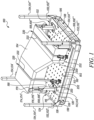
FIG. 1 is a perspective view of a rack system having a platform to support an article, in accordance with an embodiment of the present disclosure; -
FIG. 2 is a perspective view of the platform, in accordance with an embodiment of the present disclosure; -
FIG. 3 is a front perspective view of a modular stanchion of the rack system, in accordance with an embodiment of the present disclosure; -
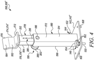
FIG. 4 is a rear perspective view of the modular stanchion of the rack system, in accordance with an embodiment of the present disclosure; -
FIG. 5 illustrates an exemplary mechanism for adjusting height of the modular stanchion, in accordance with an embodiment of the present disclosure; -
FIG. 6 is a view of a strapping system of the rack system, in accordance with an embodiment of the present disclosure; and -
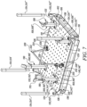
FIG. 7 is a view of the strapping system and the modular stanchions applied in conjunction with the platform to restrain and support the article with the platform, in accordance with an embodiment of the present disclosure. - Reference will now be made in detail to specific embodiments or features, examples of which are illustrated in the accompanying drawings. Wherever possible, the same reference numbers will be used throughout the drawings to refer to the same or the like parts.
- Referring to
FIG. 1 , anexemplary rack system 100 is shown. Therack system 100 may be utilized (or be adapted) to support and transport various articles (e.g., article 104) between various locations, such as, production lines, assembly lines, quality testing areas, storage areas, and shipping areas, of a manufacturing facility (not shown). Thearticle 104 may include any part or an assembly of parts of any machine. As an example, thearticle 104 may include, but not limited to, an engine, a traction device, a chassis, chassis portions, a fender, hood, and/or the like parts, associated with a machine. The reference to thearticle 104 in the present disclosure may correspond to `multiple articles' and/or a `single article'. Also, the reference to the `article 104' in the present disclosure may correspond to `various articles', implying the adaptability of therack system 100 to receive and support articles of varying sizes and dimensions. It will further be understood that thearticle 104 illustrated in theFIG. 1 and its corresponding description, as may be provided in the present disclosure, is purely exemplary. Although not limited, the manufacturing facility may correspond to one where products, such as construction machines, mining machines, work machines, at least in part or in full, are produced. Therack system 100 includes aplatform 106 and one or more modular stanchions 108. - Referring to
FIG. 2 , theplatform 106 of therack system 100 is shown and discussed. Theplatform 106 may define atop surface 102 on which thearticle 104 may be placed. Theplatform 106 can be made of any material depending on the application and/or a requirement of therack system 100. For example, in one preferred embodiment, theplatform 106 can be made of a material exhibiting high strength properties to support a weight and bulk of thearticle 104, and may include, but not limited to, steel, alloy, etc., to support relatively heavy products like an engine or various other sub-assemblies of a machine. In some embodiments, theplatform 106 can be made of wood, plastic, or composite materials. - Further, the
platform 106 includes a plurality ofengagement members 112 dispersed and arrayed uniformly across an expanse of theplatform 106. Theengagement members 112 may correspond toholes 110 structured in theplatform 106, to facilitate engagement of the modular stanchions 108 with the platform 106 (as shown inFIGs. 1 and7 ). Theengagement members 112 may be dispersed in a manner such that theengagement members 112 define identical patterns 114 of two ormore engagement members 112 across the expanse of theplatform 106. For example,FIG. 2 shows the identical patterns 114', 114", 114‴ and 114"" defined on theplatform 106. Further, when theengagement members 112 includeholes 110, theholes 110 may extend from thetop surface 102 and extend into abody 120 of theplatform 106. In some embodiments, theholes 110 may be through holes extending throughout a thickness, T, defined by theplatform 106. In some embodiments, theholes 110 may include threadable portions to threadably engage with the modular stanchions 108. - As shown in
FIG. 2 , theengagement members 112 may be dispersed across the expanse of theplatform 106 in a matrix formation and may include acoordinate system 130 definingmultiple rows 116 andmultiple columns 118. Thecoordinate system 130 may include two axes, namely an X-axis, and a Y-axis extending perpendicular to the X-axis. The X-axis may extend parallel to a first side 122 (e.g., a first longitudinal side 122) of theplatform 106 and may define thecolumns 118 of theplatform 106. The Y-axis may extend parallel to a second side 124 (e.g., a second longitudinal side 124) of theplatform 106 and may define therows 116 of theplatform 106. As shown, eachrow 116 is identified by aunique row identifier 126, and may include one or more of an alphabet, a numeric value, and/or a special character, and eachcolumn 118 is identified by aunique column identifier 128, and may include one or more of another alphabet, a numeric value, and/or a special character. In so doing, eachengagement member 112 may be identifiable (e.g., uniquely identifiable) by a concatenation of acorresponding column identifier 128 and acorresponding row identifier 126. For example, an engagement member 112' that lies in the Jth row and 5th column may be identified as J5. - The
platform 106 may further include one or more holders 132. The holders 132 may be correspondingly provided at the corners of theplatform 106. As an example, theplatform 106 may be rectangular shaped, and may accordingly define four corners at which, correspondingly, four holders 132 may be structured and arranged. The holders 132 may be designed to correspondingly receive beams or guard rails 134 (shown inFIGs. 1 and7 ). As shown inFIG. 7 , the guard rails 134 may be inserted into the holders 132 of theplatform 106 and may be vertically aligned to provide protection to thearticle 104 against external collision. The guard rails 134 may also prevent thearticle 104 from falling out of theplatform 106. For example, as shown inFIG. 7 , the guard rails 134', 134", 134‴, 134ʺʺ are inserted and received in the respective holders 132', 132", 132‴, 132"" of theplatform 106. In one preferred embodiment, the guard rails 134 may be made of any metallic material, such as, steel or an alloy, depending on the size and weight of thearticle 104. In some embodiments, the guard rails 134 can be made from other materials, such as wood, plastic, or composite materials. - As shown in
FIG. 2 , theplatform 106 may further include aplatform base 136 to support theplatform 106. Theplatform base 136 may be engageable with a transport machine (not shown) such that the platform 106 (e.g., along with thearticle 104 mounted on the platform 106) may be transported by the transport machine to a desired location. The transport machine may include a forklift, pallet jack, and/or the like machine. As an example, theplatform base 136 includes one ormore openings 138 for receiving tongs or forks (not shown) of the transport machine, and which may be lifted above ground for raising theplatform 106 above ground, thus enabling a transportation of theplatform 106 and thus thearticle 104 to its desired location. Therefore, theopenings 138 of theplatform base 136 may be dimensioned to accommodate the tongs or the forks of the transport machine. Although not limited, theplatform base 136 can be made of a metallic material, such as, steel or an alloy, or a non-metallic material, such as wood, plastic, or composite materials. - Referring to
FIGs. 3 through 5 , various parts and portions of the modular stanchion 108 of therack system 100 are shown and discussed. The modular stanchions 108 may be engaged with theplatform 106 and may be adjustable with respect to theplatform 106 for seating the article 104 (i.e., articles of varying shapes and sizes) on theplatform 106. A number of modular stanchions 108 provided are non-limiting and may vary from application to application. Details related to various parts and portions of the modular stanchions 108 and mechanisms that enable such adjustments shall be discussed in the forthcoming description. - As shown in
FIGs. 3 and4 , the modular stanchion 108 may include a base 142 that is engageable with at least twoengagement members 112 of theplatform 106. Given, theengagement members 112 are uniformly dispersed and arrayed on theplatform 106, the engagement of the base 142 with any suitable group ofengagement members 112 allows for a mounting and positioning of the modular stanchion 108 at various locations across the expanse of the platform 106 (i.e., as far as theengagement members 112 are dispersed or spread out on theplatform 106, the modular stanchions 108 can be moved around theplatform 106 for its placement on the platform 106). In accordance with various embodiments of the present disclosure, the base 142 is engageable (e.g., removably engageable) with theengagement members 112 according to the identical pattern 114 (shown inFIG. 2 ). The positioning of the base 142 with theengagement members 112 of theplatform 106 may be determined based on and/or depend on the shape and/or dimensions of thearticle 104, thus making therack system 100 modifiable to carry the article 104 (i.e., an article of different shapes and/or dimensions). - The modular stanchion 108 also includes at least two manually operated
first fasteners engagement members 112 of theplatform 106. To this end, thefirst fasteners respective shank portions engagement members 112 of theplatform 106. Theshank portions first fasteners corresponding engagement members 112 of theplatform 106. Thefirst fasteners FIG. 7 , the base 142" of the modular stanchion 108" are engaged with theengagement members 112, identified by 'I2' and 'H3' of the identical pattern 114" (shown inFIG. 2 ) of theplatform 106, using two manually operatedfirst fasteners 144", 146". - As shown in
FIG 3 , thefirst fasteners respective knobs platform 106. Theknobs gripping portions knobs first fasteners platform 106. In some embodiments, theshank portions first fasteners holes 110 of theplatform 106 when therespective knobs platform 106. - As shown in
FIGs. 3 and4 , the modular stanchion 108 includes abracket 170 having a resting portion 174 and a supporting portion 176. Thebracket 170 defines asurface 172. For example, thesurface 172 is defined on the supporting portion 176 (and optionally also on the resting portion 174). The resting portion 174 defines afirst part 182 and asecond part 184. Thefirst part 182 extends from the supporting portion 176 and thesecond part 184 extends from thefirst part 182 to an end of the resting portion 174. In some embodiments, thesecond part 184 is angled with respect to thefirst part 182 to help align and guide one or more portions of thearticle 104 onto the supporting portion 176 to be seated on the supporting portion 176. For example, as shown inFIG. 1 , the resting portion 174" and the supporting portion 176" of the modular stanchion 108" are utilized to seat thearticle 104. - Further, the modular stanchion 108 may include at least one
first sleeve 178 and at least onesecond sleeve 180. Thefirst sleeve 178 may be coupled to thebracket 170, while thesecond sleeve 180 may be coupled to the base 142. Thefirst sleeve 178 and thesecond sleeve 180 may also be telescopically movable with respect to each other such that thebracket 170 and/or thesurface 172 is extendable and retractable with respect to the base 142 and so that a height of the surface 172 (and thus the corresponding modular stanchion 108) may be adjusted with respect to the base 142. - As shown in
FIG. 5 , the modular stanchion 108 may include anexemplary mechanism 190 to adjust the height of the modular stanchion 108 with respect to theplatform 106. Themechanism 190 may include a plurality of spaced-apartfirst apertures 192 formed on afront side 194 of thefirst sleeve 178 and the same may be disposed along a length of thefirst sleeve 178, apin 200, and aspring element 206. In accordance with various embodiments, thepin 200 is configured to be biased to a first state (e.g., see state ofpin 200 inFIG. 5 ) with respect to aprimary side 198 of thesecond sleeve 180. In the first state, thepin 200 selectively engages with thefirst apertures 192 to adjust thefirst sleeve 178 with respect to thesecond sleeve 180 to extend or retract thesurface 172 with respect to the base 142. In some embodiments, thesurface 172 may be optionally or additionally defined on thefirst sleeve 178 or thesecond sleeve 180, as well. In such cases, thefirst sleeve 178 and thesecond sleeve 180 of the modular stanchion 108 may be optionally or additionally utilized to seat thearticle 104 by providing support to one or more sides (e.g., one or more lateral sides or surfaces) of thearticle 104. - The
pin 200 may include aknob portion 202 and arod portion 204. Therod portion 204 of thepin 200 may be dimensioned to selectively slide into each one of thefirst apertures 192 formed in thefirst sleeve 178 via thesecond aperture 196 formed in thesecond sleeve 180. During a height adjustment of the modular stanchions 108 or when extending or retracting thesurface 172 with respect to the base 142, therod portion 204 of thepin 200 may be also configured to be removed from thefirst aperture 192 of thefirst sleeve 178 and re-inserted into anotherfirst aperture 192 of thefirst sleeve 178 so as to switch from one height of the corresponding modular stanchion 108 to another height of the corresponding modular stanchion 108. This is because theapertures 192 may be provided lengthwise on the first sleeve 178 (i.e., along a length of the first sleeve 178). - The
spring element 206 may be inserted between theknob portion 202 and theprimary side 198 of thesecond sleeve 180. Thespring element 206 may be configured to mutually co-operate with thepin 200 and thefirst sleeve 178 such that in a free state of thespring element 206, thespring element 206 may bias thepin 200 in the first state for engagement with one of thefirst apertures 192 of thefirst sleeve 178. To this end, thespring element 206 provides a controlled amount of tension or force between thepin 200 and thesecond sleeve 180. Notably, a biasing force applied by thespring element 206 on thepin 200 keeps thepin 200 in engagement with thefirst sleeve 178. The tension of thespring element 206 may be sufficient to prevent inadvertent release (i.e., disengagement of thepin 200 and the first sleeve 178) due to vibrations, jolting, jarring, bouncing, bumping, and/or the like, that may occur during transportation of thearticle 104. As shown inFIG. 5 , thespring element 206 is embodied in the form of a compression spring. However, other types of spring elements known in the art may be used in lieu of the compression spring shown inFIG. 5 . - In some embodiments, the modular stanchion 108 may include a
height reference system 210 for measuring the height of the modular stanchion 108, as shown inFIG. 4 . Theheight reference system 210 may be used as a reference to adjust thefirst sleeve 178 with respect to thesecond sleeve 180. As shown inFIG. 4 , theheight reference system 210 includesreference characters 216, such as, alphabetic letters and/or the like, indicated on arear side 212 of the first sleeve 178 (e.g., along a length of the first sleeve 178). Thereference characters 216 may be indicated on specific positions or intervals of movement corresponding to the intervals between thefirst apertures 192 of thefirst sleeve 178 and may be viewed through a side opening 186 (seeFIGs. 4 and5 ) provided in thesecondary side 214 of thesecond sleeve 180. In some embodiments, one or more parts of the modular stanchion 108, such as the base 142,first sleeve 178, and thesecond sleeve 180, and the one or more of the other parts described above, can be made of the same material as that of theplatform 106 and/or theplatform base 136. - In some embodiments, as shown in
FIG. 3 , the modular stanchion 108 includesfirst retainer members first fasteners first retainer members knobs first fasteners first retainer members first fasteners FIG. 3 , thefirst retainer member 156 may include aloop portion 164 that is designed to fit around theknob 152 of thefirst fastener 144. Thefirst retainer member 156 further includes acable portion 166 coupled to theloop portion 164 on one end and secured to thesecond sleeve 180 of the modular stanchion 108 on an opposite end. Theloop portion 164 and thecable portion 166 may be made of the same or different material and may exemplarily include one or more of metal, plastic, fiber, or any similar material, to perform the functions described. - As shown in
FIGs. 3 and4 , the base 142 of the modular stanchion 108 also includes one ormore guides 168 to be aligned with at least twoother engagement members 112 to be mated with the at least twoother engagement members 112 of theplatform 106. The twoother engagement members 112 may be a part of each of the identical patterns 114 (shown inFIG. 2 ). For example, as shown inFIG. 7 , theguide 168" of the base 142" of the modular stanchion 108" is mated with theengagement member 112 identified by '13' of the identical pattern 114" of theplatform 106. - Referring to
FIG. 6 , the strappingsystem 220 of therack system 100 is shown. One or more strappingsystems 220 are utilized to secure thearticle 104 to theplatform 106 of the rack system 100 (as shown inFIG. 1 ). To this end, each strappingsystem 220 may include astrap 222 andend plates - The
strap 222 may define afirst end 224 and asecond end 226. Thestrap 222 may be made of any flexible (but a strong) material, such as, polyester, steel, and the like. Although not limited, thestrap 222 may also have elastic properties. In use with theplatform 106 to support thearticle 104, thestrap 222 may be wrapped around thearticle 104 to restrain (e.g., tightly restrain) the article's movement with respect to theplatform 106 such that the article cannot fall off the platform during transportation. - The
end plates ends strap 222, for example, afirst end plate 228 is disposed at thefirst end 224 and asecond end plate 230 is disposed at thesecond end 226 of thestrap 222. The strappingsystem 220 further includes at least two manually operatedsecond fasteners first end plate 228 and thesecond end plate 230 withcorresponding engagement members 112 of theplatform 106. To this end, thesecond fasteners respective shank portions engagement members 112 of theplatform 106. Theshank portions second fasteners first end plate 228 and thesecond end plate 230 of the strappingsystem 220, to engage the respectivefirst end plate 228 and thesecond end plate 230 with thecorresponding engagement members 112 of theplatform 106. Thesecond fasteners FIG. 7 , thesecond end plate 230 of the strappingsystem 220 is engaged with theengagement members 112 identified by A7 of theplatform 106, using the manually operatedsecond fastener 234. - The
second fasteners respective knobs first end plate 228 and thesecond end plate 230 from thecorresponding engagement members 112 of theplatform 106. For example, theknob 252 may include one or moregripping portions 218 to maintain a secure hold of theknob 252 while manually fastening/unfastening thesecond fastener 232 from theplatform 106. In some embodiments, theshank portion 236 of thesecond fastener 232 is threadably engaged with theholes 110 of theplatform 106 when theknob 252 is manually operated to fasten thefirst end plate 228 with theplatform 106. - As shown in
FIG. 6 , the strappingsystem 220 includessecond retainer member 240 to retain thesecond fastener 232 with thefirst end plate 228. Thesecond retainer member 240 may be designed to fit around theknob 252 of thesecond fastener 232 and hold it securely in place against thefirst end plate 228. Thesecond retainer member 240 may be designed in a variety of shapes and sizes to fit different types ofsecond fastener 232 for coupling with thefirst end plate 228. For example, theretainer member 240 may include aloop portion 244 that is designed to fit around theknob 252 of thesecond fastener 232. Theretainer member 240 further includes alatch portion 246 coupled to theloop portion 244 on one end and secured to thefirst end plate 228, via alatch receiving slot 248, on an opposite end. Theloop portion 244 and thelatch portion 246 may be made of the same or different material, including metal, plastic, fiber, or any similar material to perform the functions described. The strappingsystem 220 may include one or more additional second retainer members similar to thesecond retainer member 240 to retain thesecond fastener 234 with thesecond end plate 230. - The strapping
system 220 may further include at least onetensioning mechanism 250 for adjusting a tension of thestrap 222 of the strappingsystem 220 for securing thearticle 104. Thetensioning mechanism 250 of the strappingsystem 220 may function in a known manner and the details of which are not described herein, for the sake of brevity of the disclosure. - The
rack system 100 of the present disclosure, having themultiple engagement members 112 dispersed and arrayed uniformly across the expanse of theplatform 106, allows easy customization to support and transport the article 104 (i.e., articles of varying sizes and dimensions) to desired locations. Theengagement members 112 dispersed across the expanse of theplatform 106 provide the flexibility to mount and position one or more modular stanchions 108 at various locations on theplatform 106. Depending upon the dimensions of thearticle 104 to be supported by therack system 100, the modular stanchions 108 are suitably and modularly mounted and positioned on theplatform 106 for supporting thearticle 104 on theplatform 106. - For example, as shown in
FIG. 7 , the modular stanchions 108', 108", 108"', 108"" are mounted and positioned on theplatform 106 at the desired locations. In order to mount and position the modular stanchion 108 on theplatform 106, thefirst fasteners more guides 168 provided on the base 142 of the modular stanchion 108 may be engaged with thecorresponding engagement members 112 of theplatform 106. The height of each modular stanchion 108 may be adjusted to achieve a desired height by removing therod portion 204 of thepin 200 from thefirst apertures 192 of thefirst sleeve 178, moving thefirst sleeve 178 with respect to thesecond sleeve 180, and at the desired height re-inserting therod portion 204 of thepin 200 into a correspondingfirst aperture 192 of thefirst sleeve 178, as shown inFIGs. 3-5 . As shown inFIG. 7 , different modular stanchions 108', 108", 108"', 108"" can be adjusted to different heights, to meet the seating requirements of thearticle 104. If additional or lesser modular stanchions 108 are needed to support thearticle 104, the number of the modular stanchions 108 can be varied accordingly. - Upon mounting and positioning the modular stanchions 108 with the desired heights, the
article 104 is brought forth and then seated on thesurfaces 172 defined by the modular stanchion 108 of theplatform 106. Further, thearticle 104 is secured with the strappingsystem 220. In order to secure thearticle 104 with the strappingsystem 220, thefirst end plate 228 and thesecond end plate 230 disposed at the respectivefirst end 224 and thesecond end 226 of thestrap 222 are engaged with another set of one ormore engagement members 112 of theplatform 106, as shown inFIG. 7 . A tension of thestrap 222 is then adjusted for securing thearticle 104 using thetensioning mechanism 250. In some embodiments, the guard rails 134', 134", 134‴, 134ʺʺ are inserted in the respective holders 132', 132", 132‴, 132ʺʺ of theplatform 106 to protect thearticle 104 from external collision and/or fall off. - With the modular functionality offered by the
rack system 100, a decrease in demand for onearticle 104 and/or an increase in demand for anotherarticle 104, does not necessitate a discarding of therack system 100. Rather, with themultiple engagement members 112 and the modular stanchions 108, therack system 100 can easily be reconfigured and transformed into arack system 100 than can support and transport thenew article 104, and thus multipleother articles 104, in turn easing inventory management and associated labor. For example, therack system 100 can be easily reconfigured by disengaging the modular stanchions 108 and the strappingsystem 220 from theengagement members 112 of theplatform 106 and re-positioning the modular stanchions 108 and the strappingsystem 220 on theplatform 106 as per the shape and dimensions of the new article. The identical patterns 114 of two ormore engagement members 112 enable the modular stanchions 108 to be placed anywhere across the expanse of theplatform 106 according to the identical pattern 114. Also, theunique row identifier 126 and theunique column identifier 128 of theplatform 106 makes it easy to identify theengagement members 112 to be used for mounting the modular stanchions 108 and theheight reference system 210 assists in achieving the desired heights of the modular stanchions 108. Effectively, therack system 100 is adapted to supportvarious articles 104 of different sizes and dimensions by adjusting the positioning and height of the modular stanchions 108 on theplatform 106. Moreover, the manual operations associated with disengaging the modular stanchions 108 and the strappingsystem 220 from theengagement members 112 of theplatform 106 and re-positioning the modular stanchions 108 and the strappingsystem 220 enable therack system 100 to be used with less or no tooling. - It will be apparent to those skilled in the art that various modifications and variations can be made to the method and/or system of the present disclosure without departing from the scope of the disclosure. Other embodiments will be apparent to those skilled in the art from consideration of the specification and practice of the method and/or system disclosed herein. It is intended that the specification and examples be considered as exemplary only, with a true scope of the disclosure being indicated by the following claims and their equivalent.
Claims (15)
- A rack system (100) for supporting and transporting various articles (104) between various locations of a manufacturing facility, the rack system (100) comprising:a platform (106) having a plurality of engagement members (112) dispersed and arrayed uniformly across an expanse of the platform (106); andone or more modular stanchions (108), each modular stanchion (108) of the one or more modular stanchions (108) including:a base (142) engageable with at least two engagement members (112) of the plurality of engagement members (112) for mounting and positioning the corresponding modular stanchion (108) at various locations across the expanse of the platform (106); anda surface (172) configured to seat a corresponding article (104) and being extendable and retractable with respect to the base (142).
- The rack system (100) of claim 1, wherein each modular stanchion (108) includes at least one first sleeve (178) and at least one second sleeve (180), the at least one first sleeve (178) and the at least one second sleeve (180) being telescopically movable with respect to each other such that the surface (172) is extendable and retractable with respect to the base (142).
- The rack system (100) of claim 2, wherein the modular stanchion (108) further includes a mechanism (190) to adjust the height of the modular stanchions (108), wherein the mechanism (190) includes:apertures (192) formed in the at least one first sleeve (178); anda pin (200) configured to be biased to a first state with respect to the at least one second sleeve (180), wherein in the first state, the pin (200) selectively engages with the apertures (192) to adjust the at least one first sleeve (178) with respect to the at least one second sleeve (180) to extend or retract the surface (172) with respect to the base (142).
- The rack system (100) of claim 1, wherein each modular stanchion (108) includes at least two manually operated first fasteners (144, 146) to engage the base (142) with the at least two engagement members (112).
- The rack system (100) of claim 4, wherein each modular stanchion (108) includes first retainer members (156, 158) to correspondingly retain the at least two manually operated first fasteners (144, 146) with the base (142).
- The rack system (100) of claim 1, wherein the plurality of engagement members (112) define identical patterns (114) of two or more engagement members (112) of the plurality of engagement members (112) across the expanse, and wherein the at least two engagement members (112) are engageable with the base (142) according to the identical pattern (114).
- The rack system (100) of claim 6, wherein the at least two engagement members (112) correspond to at least two first engagement members (112), the base (142) including one or more guides (168) to be aligned with at least two second engagement members (112) to be mated with the at least two second engagement members (112), wherein the at least two second engagement members (112) are part of each of the identical patterns (114).
- The rack system (100) of claim 1, wherein the plurality of engagement members (112) are dispersed across the expanse of the platform (106) in a matrix formation defining a plurality of rows (116) and a plurality of columns (118), each row of the plurality of rows (116) being identified by a unique row identifier (126) and each column of the plurality of columns (118) being identified by a unique column identifier (128) such that each engagement member (112) of the plurality of engagement members (112) is identifiable by a concatenation of a corresponding column identifier (128) and a corresponding row identifier (126).
- The rack system (100) of claim 1, wherein each modular stanchion (108) includes a resting portion (174) and a supporting portion (176), the resting portion (174) defines a first part (182) and a second part (184), the first part (182) extends from the supporting portion (176) and the second part (184) extends from the first part (182) to an end of the resting portion (174), wherein the second part (184) is angled with respect to the first part (182).
- The rack system (100) of claim 1, further includes a strapping system (220) for securing the various articles (104) to the platform (106).
- The rack system (100) of claim 10, wherein the strapping system (220) includes at least one tensioning mechanism (250) for adjusting a tension of the strapping system (220) for securing the various articles (104).
- The rack system (100) of claim 10, wherein the strapping system (220) includes a strap (222) defining a first end (224) and a second end (226), a first end plate (228) being disposed at the first end (224) and a second end plate (230) being disposed at the second end (226), at least two manually operated second fasteners (232, 234) to correspondingly retain the first end plate (228) and the second end plate (230) with corresponding engagement members (112) of the plurality of engagement members (112).
- The rack system (100) of claim 12, wherein the strapping system (220) includes second retainer members (240) to correspondingly retain the at least two second fasteners (232, 234) correspondingly with the first end plate (228) and the second end plate (230).
- The rack system (100) of claim 1, wherein the plurality of engagement members (112) correspond to a plurality of holes (110) structured in the platform (106).
- The rack system (100) of claim 1, wherein the platform (106) is a steel platform.
Applications Claiming Priority (1)
| Application Number | Priority Date | Filing Date | Title |
|---|---|---|---|
| GB2303631.2A GB2628104A (en) | 2023-03-13 | 2023-03-13 | Rack system for supporting and transporting various articles |
Publications (1)
| Publication Number | Publication Date |
|---|---|
| EP4431410A1 true EP4431410A1 (en) | 2024-09-18 |
Family
ID=86052670
Family Applications (1)
| Application Number | Title | Priority Date | Filing Date |
|---|---|---|---|
| EP24157713.9A Pending EP4431410A1 (en) | 2023-03-13 | 2024-02-14 | Rack system for supporting and transporting various articles |
Country Status (2)
| Country | Link |
|---|---|
| EP (1) | EP4431410A1 (en) |
| GB (1) | GB2628104A (en) |
Citations (8)
| Publication number | Priority date | Publication date | Assignee | Title |
|---|---|---|---|---|
| US4121817A (en) * | 1976-10-27 | 1978-10-24 | Rudolf Pavlovsky | Arrangement for clamping workpieces |
| US5305992A (en) * | 1993-04-19 | 1994-04-26 | The Budd Company | Measuring fixture with gauge ball |
| US20050110204A1 (en) | 2003-11-25 | 2005-05-26 | Chi-Hung Shen | Reconfigurable mechanical fixturing pallets for assembly lines |
| US20100140860A1 (en) * | 2008-12-05 | 2010-06-10 | Gm Global Technology Operations, Inc. | Flexible support assembly for vehicle tooling plates |
| US20110006020A1 (en) * | 2009-07-10 | 2011-01-13 | Zeledyne, Llc | Rack assembly for shipping glass panels |
| CN104493760A (en) * | 2014-11-28 | 2015-04-08 | 天奇自动化工程股份有限公司 | Assembled pallet for combined assembly of automobiles |
| CN204472952U (en) * | 2015-01-16 | 2015-07-15 | 北京汽车研究总院有限公司 | A kind of assembly tooling of dynamic assembly |
| US20180312296A1 (en) * | 2017-04-26 | 2018-11-01 | Can Do Logistics Llc | Project material storage and transportation device and system |
Family Cites Families (5)
| Publication number | Priority date | Publication date | Assignee | Title |
|---|---|---|---|---|
| US5153505A (en) * | 1991-11-05 | 1992-10-06 | The Johns Hopkins University | Adaptable multiport test fixture system |
| US6644637B1 (en) * | 2002-09-13 | 2003-11-11 | General Motors Corporation | Reconfigurable workholding fixture |
| CA2707163A1 (en) * | 2007-11-30 | 2009-06-04 | Flow International Corporation | Flexible header system for machining workpieces |
| CN205043494U (en) * | 2015-10-29 | 2016-02-24 | 浙江永誉机械制造有限公司 | Process omnipotent tool equipment of special -shaped blade |
| CN111376219A (en) * | 2020-04-07 | 2020-07-07 | 一汽奔腾轿车有限公司 | Flexible and modularized assembling tool table for power assembly |
-
2023
- 2023-03-13 GB GB2303631.2A patent/GB2628104A/en active Pending
-
2024
- 2024-02-14 EP EP24157713.9A patent/EP4431410A1/en active Pending
Patent Citations (8)
| Publication number | Priority date | Publication date | Assignee | Title |
|---|---|---|---|---|
| US4121817A (en) * | 1976-10-27 | 1978-10-24 | Rudolf Pavlovsky | Arrangement for clamping workpieces |
| US5305992A (en) * | 1993-04-19 | 1994-04-26 | The Budd Company | Measuring fixture with gauge ball |
| US20050110204A1 (en) | 2003-11-25 | 2005-05-26 | Chi-Hung Shen | Reconfigurable mechanical fixturing pallets for assembly lines |
| US20100140860A1 (en) * | 2008-12-05 | 2010-06-10 | Gm Global Technology Operations, Inc. | Flexible support assembly for vehicle tooling plates |
| US20110006020A1 (en) * | 2009-07-10 | 2011-01-13 | Zeledyne, Llc | Rack assembly for shipping glass panels |
| CN104493760A (en) * | 2014-11-28 | 2015-04-08 | 天奇自动化工程股份有限公司 | Assembled pallet for combined assembly of automobiles |
| CN204472952U (en) * | 2015-01-16 | 2015-07-15 | 北京汽车研究总院有限公司 | A kind of assembly tooling of dynamic assembly |
| US20180312296A1 (en) * | 2017-04-26 | 2018-11-01 | Can Do Logistics Llc | Project material storage and transportation device and system |
Also Published As
| Publication number | Publication date |
|---|---|
| GB202303631D0 (en) | 2023-04-26 |
| GB2628104A (en) | 2024-09-18 |
Similar Documents
| Publication | Publication Date | Title |
|---|---|---|
| US4921100A (en) | Rack latch assembly | |
| US4911084A (en) | Pallet | |
| US4774892A (en) | Article restraining means for pallets | |
| DE10032812C2 (en) | Device for the transport and storage of goods | |
| US6986431B2 (en) | Transportation and storage cart | |
| EP2523864A1 (en) | Device for transporting objects | |
| WO2002051726A2 (en) | Adjustable auxiliary conveyor | |
| US8177442B2 (en) | Digital printing machine and platen assembly for printing on multiple garment portions | |
| GB2628104A (en) | Rack system for supporting and transporting various articles | |
| EP2207724B1 (en) | Storage product carrier for sleeve-shaped storage products, and storage shelf therefore | |
| WO2019228645A1 (en) | Transport device and transport vehicle | |
| DE102017206136B4 (en) | System for transporting differently designed components | |
| DE102013104045B3 (en) | Device for presenting goods | |
| JP7079215B2 (en) | Sign equipment loading device | |
| DE102018001451A1 (en) | Base of a molding removal machine | |
| EP3623337B1 (en) | Forklift pocket and connection device for a forklift pocket on an article to be carried | |
| US6311371B1 (en) | Pallet strip | |
| DE10054644A1 (en) | Plate-form press with block and tools, with holding device in form of holding bolt or block member pre-tensioned by spring | |
| CA3109922A1 (en) | Cooler panel lifting assembly | |
| DE102018123223A1 (en) | Transport assembly with a trolley for transporting objects | |
| US20030226949A1 (en) | Support for electronics assembly | |
| DE9313691U1 (en) | Shelf support for placing an intermediate shelf in a transport container | |
| US12129159B2 (en) | Systems and methods for modular carriage width adjustment | |
| CN224241550U (en) | Structural arrangement of a central support for flat articles | |
| EP3702212B1 (en) | Load unit of column-shaped transport containers, assembly of load units and method for securing load |
Legal Events
| Date | Code | Title | Description |
|---|---|---|---|
| PUAI | Public reference made under article 153(3) epc to a published international application that has entered the european phase |
Free format text: ORIGINAL CODE: 0009012 |
|
| STAA | Information on the status of an ep patent application or granted ep patent |
Free format text: STATUS: THE APPLICATION HAS BEEN PUBLISHED |
|
| AK | Designated contracting states |
Kind code of ref document: A1 Designated state(s): AL AT BE BG CH CY CZ DE DK EE ES FI FR GB GR HR HU IE IS IT LI LT LU LV MC ME MK MT NL NO PL PT RO RS SE SI SK SM TR |
|
| STAA | Information on the status of an ep patent application or granted ep patent |
Free format text: STATUS: REQUEST FOR EXAMINATION WAS MADE |
|
| 17P | Request for examination filed |
Effective date: 20250310 |