EP4431397A1 - Improved energy recovery and thermal control utilizing heat pump - Google Patents
Improved energy recovery and thermal control utilizing heat pump Download PDFInfo
- Publication number
- EP4431397A1 EP4431397A1 EP24164249.5A EP24164249A EP4431397A1 EP 4431397 A1 EP4431397 A1 EP 4431397A1 EP 24164249 A EP24164249 A EP 24164249A EP 4431397 A1 EP4431397 A1 EP 4431397A1
- Authority
- EP
- European Patent Office
- Prior art keywords
- medium
- subsystem
- heat exchanger
- vehicle
- cabin
- Prior art date
- Legal status (The legal status is an assumption and is not a legal conclusion. Google has not performed a legal analysis and makes no representation as to the accuracy of the status listed.)
- Pending
Links
Images


Classifications
-
- B—PERFORMING OPERATIONS; TRANSPORTING
- B64—AIRCRAFT; AVIATION; COSMONAUTICS
- B64D—EQUIPMENT FOR FITTING IN OR TO AIRCRAFT; FLIGHT SUITS; PARACHUTES; ARRANGEMENT OR MOUNTING OF POWER PLANTS OR PROPULSION TRANSMISSIONS IN AIRCRAFT
- B64D13/00—Arrangements or adaptations of air-treatment apparatus for aircraft crew or passengers, or freight space
- B64D13/06—Arrangements or adaptations of air-treatment apparatus for aircraft crew or passengers, or freight space the air being conditioned
-
- B—PERFORMING OPERATIONS; TRANSPORTING
- B64—AIRCRAFT; AVIATION; COSMONAUTICS
- B64D—EQUIPMENT FOR FITTING IN OR TO AIRCRAFT; FLIGHT SUITS; PARACHUTES; ARRANGEMENT OR MOUNTING OF POWER PLANTS OR PROPULSION TRANSMISSIONS IN AIRCRAFT
- B64D13/00—Arrangements or adaptations of air-treatment apparatus for aircraft crew or passengers, or freight space
- B64D13/06—Arrangements or adaptations of air-treatment apparatus for aircraft crew or passengers, or freight space the air being conditioned
- B64D13/08—Arrangements or adaptations of air-treatment apparatus for aircraft crew or passengers, or freight space the air being conditioned the air being heated or cooled
-
- B—PERFORMING OPERATIONS; TRANSPORTING
- B64—AIRCRAFT; AVIATION; COSMONAUTICS
- B64D—EQUIPMENT FOR FITTING IN OR TO AIRCRAFT; FLIGHT SUITS; PARACHUTES; ARRANGEMENT OR MOUNTING OF POWER PLANTS OR PROPULSION TRANSMISSIONS IN AIRCRAFT
- B64D13/00—Arrangements or adaptations of air-treatment apparatus for aircraft crew or passengers, or freight space
- B64D13/06—Arrangements or adaptations of air-treatment apparatus for aircraft crew or passengers, or freight space the air being conditioned
- B64D2013/0603—Environmental Control Systems
- B64D2013/0614—Environmental Control Systems with subsystems for cooling avionics
-
- B—PERFORMING OPERATIONS; TRANSPORTING
- B64—AIRCRAFT; AVIATION; COSMONAUTICS
- B64D—EQUIPMENT FOR FITTING IN OR TO AIRCRAFT; FLIGHT SUITS; PARACHUTES; ARRANGEMENT OR MOUNTING OF POWER PLANTS OR PROPULSION TRANSMISSIONS IN AIRCRAFT
- B64D13/00—Arrangements or adaptations of air-treatment apparatus for aircraft crew or passengers, or freight space
- B64D13/06—Arrangements or adaptations of air-treatment apparatus for aircraft crew or passengers, or freight space the air being conditioned
- B64D2013/0603—Environmental Control Systems
- B64D2013/0625—Environmental Control Systems comprising means for distribution effusion of conditioned air in the cabin
-
- B—PERFORMING OPERATIONS; TRANSPORTING
- B64—AIRCRAFT; AVIATION; COSMONAUTICS
- B64D—EQUIPMENT FOR FITTING IN OR TO AIRCRAFT; FLIGHT SUITS; PARACHUTES; ARRANGEMENT OR MOUNTING OF POWER PLANTS OR PROPULSION TRANSMISSIONS IN AIRCRAFT
- B64D13/00—Arrangements or adaptations of air-treatment apparatus for aircraft crew or passengers, or freight space
- B64D13/06—Arrangements or adaptations of air-treatment apparatus for aircraft crew or passengers, or freight space the air being conditioned
- B64D2013/0603—Environmental Control Systems
- B64D2013/064—Environmental Control Systems comprising more than one system, e.g. dual systems
-
- B—PERFORMING OPERATIONS; TRANSPORTING
- B64—AIRCRAFT; AVIATION; COSMONAUTICS
- B64D—EQUIPMENT FOR FITTING IN OR TO AIRCRAFT; FLIGHT SUITS; PARACHUTES; ARRANGEMENT OR MOUNTING OF POWER PLANTS OR PROPULSION TRANSMISSIONS IN AIRCRAFT
- B64D13/00—Arrangements or adaptations of air-treatment apparatus for aircraft crew or passengers, or freight space
- B64D13/06—Arrangements or adaptations of air-treatment apparatus for aircraft crew or passengers, or freight space the air being conditioned
- B64D2013/0603—Environmental Control Systems
- B64D2013/0674—Environmental Control Systems comprising liquid subsystems
-
- B—PERFORMING OPERATIONS; TRANSPORTING
- B64—AIRCRAFT; AVIATION; COSMONAUTICS
- B64D—EQUIPMENT FOR FITTING IN OR TO AIRCRAFT; FLIGHT SUITS; PARACHUTES; ARRANGEMENT OR MOUNTING OF POWER PLANTS OR PROPULSION TRANSMISSIONS IN AIRCRAFT
- B64D13/00—Arrangements or adaptations of air-treatment apparatus for aircraft crew or passengers, or freight space
- B64D13/06—Arrangements or adaptations of air-treatment apparatus for aircraft crew or passengers, or freight space the air being conditioned
- B64D2013/0603—Environmental Control Systems
- B64D2013/0688—Environmental Control Systems with means for recirculating cabin air
Definitions
- Exemplary embodiments pertain to one or more subsystems of an aircraft, and more particularly, to a vapor cooling system thermally coupled to one or more subsystems of an environmental control system.
- a typical commercial aircraft includes several nonintegrated cooling systems configured to provide temperature control to various regions of the aircraft.
- an aircraft environmental control system primarily provides heating and cooling for the aircraft cabin area.
- a galley chiller system is dedicated to refrigerating the food carts in the galleys located throughout the aircraft.
- Yet another system is dedicated to cooling the cargo area of the aircraft. Since each system has a significant weight and power requirement, the overall efficiency of the aircraft is affected by these nonintegrated systems.
- a vehicle system includes a first medium provided from a first subsystem and a vapor cooling system having a closed loop vapor compression cycle through which a cooling medium circulates.
- the first subsystem is fluidly coupled to the vapor cooling system.
- a second medium is provided from a second subsystem and the second subsystem is fluidly coupled to the vapor cooling system.
- the first subsystem is a cabin discharge air system.
- the first medium is cabin recirculation air.
- the second subsystem is a cabin discharge air system.
- the second medium is cabin discharge air.
- the second subsystem is an electronics cooling subsystem.
- the vapor cooling system is a heat pump.
- the vapor cooling system includes a first heat exchanger and a second heat exchanger.
- the first subsystem is fluidly coupled to the first heat exchanger and the second subsystem is fluidly coupled to the second heat exchanger.
- an outlet of the first heat exchanger is fluidly coupled to a cabin of the vehicle such that a conditioned first medium output from the first heat exchanger is provided to the cabin.
- an outlet of the first heat exchanger is fluidly coupled to an air mixing unit of the vehicle such that a conditioned first medium output from the first heat exchanger is provided to the air mixing unit.
- an outlet of the first heat exchanger is fluidly coupled to an environmental control system of the vehicle such that a conditioned first medium output from the first heat exchanger is provided to the environmental control system.
- an outlet of the first heat exchanger is fluidly coupled to an atmosphere external to the vehicle.
- a method including conditioning a first medium provided from a first subsystem of a vehicle at a vapor cooling system to form a conditioned first medium and recovering energy from a second medium provided from a second subsystem of the vehicle at the vapor cooling system.
- the vapor cooling system includes a closed-loop vapor compression cycle and the recovered energy is used to condition the first medium.
- the vapor cooling system includes a first heat exchanger and a second heat exchanger and conditioning the first medium occurs at the first heat exchanger using a cooling medium and conditioning the second medium occurs at the second heat exchanger using the cooling medium.
- At least one the first subsystem and the second subsystem is a cabin discharge system.
- the second subsystem is an electronics cooling subsystem.
- the aircraft includes a cabin 12 fluidly coupled to the air management system 10.
- the cabin 12 is a compartment of an aircraft that includes an internal environment.
- cabin 12 may be configured to house people, cargo, and the like therein.
- the air management system 10 is configured to provide conditioned air to the cabin 12 as well as remove used or contaminated air from the cabin 12.
- the air management system 10 includes an environmental control system 13 including at least one air conditioning unit or pack 14, and a cabin discharge air system 16.
- air management system 10 is illustrated and described herein with reference to an aircraft 11, it should be understood that the systems and techniques discussed herein may be used for a variety of ventilation systems.
- cabin 12 may be replaced with any pressurized cabin.
- systems described herein may be used with submarine ventilation systems, personnel carrier ventilation systems, bus ventilation systems, or any other ventilation system that may use pressurized air.
- a medium such as air for example, is provided from one or more sources 18 to the air management system 10.
- suitable sources 18 include but are not limited to an engine of the aircraft 11, an auxiliary power unit of the aircraft 11, and fresh, outside air.
- the medium output from these sources 18 is provided to the one or more air conditioning units 14 of the environmental control system 13.
- the medium is conditioned. This conditioning includes altering one or more of a pressure, temperature, humidity, or flow rate of the medium based on an operating condition of the aircraft.
- the medium output or discharged from the one or more air conditioning units 14 of the environmental control system 13 may be used to maintain a target range of pressures, temperatures, and/or humidity within the cabin 12.
- the medium discharged from the air conditioning units 14 is provided to an air mixing unit or mixing manifold 20 via one or more outlet ducts 22.
- at least one duct 24 of the cabin discharge air system 16 extends from the cabin 12 to the air mixing unit 20 to deliver air exhausted from the cabin 12 to the air mixing unit 20.
- the cabin recirculating air is mixed with the medium output from the one or more air conditioning units 14 to achieve a mixed medium having one or more desired parameters, such as temperature, pressure, and humidity for example.
- the mixed medium is delivered to the cabin 12 from the air mixing unit 20 via one or more conduits 26.
- the mixed medium may be delivered to the cabin 12 via a ventilation system arranged near a ceiling of the cabin 12.
- the mixed medium typically circulates from the top of the cabin 12 toward the floor and is distributed to a plurality of individual vents 28 of the ventilation system mounted spaced laterally between the front and rear of the cabin 12.
- the temperature of the air collected within the cabin discharge air system 16 may be different than the temperature of the air provided to the cabin 12 from the air mixing unit 20. Accordingly, in some embodiments, the portion of the cabin air intended to be returned to the air mixing unit 20 via one or more conduits 24, also referred to herein as "cabin recirculation air,” may be conditioned at a location downstream from an outlet of the cabin 12 and upstream from the air mixing unit 20. In an embodiment, conditioning the cabin recirculation air includes cooling or heating the cabin recirculation air.
- a flow of a first medium A 1 such as the cabin recirculation air for example, provided from a first subsystem of the vehicle, may be cooled by a cooling medium B within at least one heat exchanger.
- the cooling medium B is a fluid contained within a separate or secondary vapor cooling system 40, such as having a closed loop vapor compression cycle for example.
- the vapor cooling system 40 is thermally coupled to the air management system 10 at the at least one heat exchanger.
- the vapor cooling system 40 includes a compressor 42, a first heat exchanger 44, and expansion valve 46, and a second heat exchanger 48 arranged to form a closed fluid loop through which the cooling medium circulates.
- the cooling medium B may be any suitable fluid including refrigerant, or any other fluid having suitable thermodynamic properties for proper operation of a vapor compression cycle.
- the compressor 42 may be operably coupled to an electric motor.
- the compressor 42 may be alternatively or additionally driven by energy from another source.
- the compressor 42 may be operably coupled to a turbine via a shaft and energy extracted within the turbine may be used to drive the compressor 42.
- the vapor cooling system 40 may additionally include a reversing valve 50 operable to selectively control the direction of flow of the cooling medium B in either a first direction or a second direction within the fluid loop, such as based on a temperature of the first medium A 1 output from the first subsystem.
- the vapor cooling system 40 may be considered a heat pump. Accordingly, when the reversing valve 50 is in a first position, the cooling medium B is configured to flow from the compressor 42 to the first heat exchanger 44, to the expansion valve 46, to the second heat exchanger 48, as shown in FIG. 2 .
- the first heat exchanger 44 is operable as a condenser or heat rejection heat exchanger and the second heat exchanger 48 is operable as an evaporator or a heat absorption heat exchanger.
- the cooling medium B is configured to flow from the compressor 42 to the second heat exchanger 48, to the expansion valve 46, and to the first heat exchanger 44 in series.
- the second heat exchanger 48 is operable as a condenser or heat rejection heat exchanger and the first heat exchanger 44 is operable as an evaporator or a heat absorption heat exchanger.
- the first medium A 1 may be provided to a heat exchanger of the vapor cooling system 40, such as the second heat exchanger 48 operable as a heat absorption heat exchanger of the vapor cooling system 40. Accordingly, within the second heat exchanger 48, heat is configured to transfer from the first medium A 1 to the cooling medium B. Similarly, when the first medium A 1 needs to be heated, the position of the reversing valve 50 may be adjusted such that the second heat exchanger 48 is configured as the heat rejecting heat exchanger.
- heat from the cooling medium B is configured to transfer to the first medium A 1 .
- the conditioned first medium A 1 for example, cabin recirculation air output from the heat exchanger 48 of the vapor cooling system 40 may be delivered to same first subsystem, or alternatively, to a different subsystem of the vehicle.
- the conditioned first medium A 1 provided at the outlet of the second heat exchanger 48 may be returned to the air mixing unit 20 as previously described, may be returned directly to the cabin 12, or alternatively, or additionally may be provided to another system of the vehicle, such as the environmental control system 13 for example.
- a second medium A 2 provided from a second subsystem is arranged in a heat transfer relationship with the cooling medium B at the first heat exchanger 44.
- the second medium A 2 is a flow of cabin discharge air, which is air exhausted from the cabin and that would normally be discharged overboard from the aircraft.
- the first medium A 1 and the second medium A 2 may both be provided from the same subsystem, such as the cabin discharge system 16 for example.
- heat is configured to transfer from the cooling medium B to the second medium A 2 .
- the cooling medium B is configured to receive heat from the second medium A 2 .
- the second medium A 2 is cabin discharge air
- the conditioned second medium A 2 output from the first heat exchanger 44 may be exhausted overboard, into the ambient or external atmosphere surrounding the vehicle.
- cabin discharge air By using cabin discharge air, a secondary flow source, such as a fan for example, would not be required when the aircraft is at altitude because of the pressure differential of the cabin and the outside ambient pressure.
- cabin discharge air is illustrated and described herein as the second medium A 2 , it should be appreciated that embodiments where the second medium A 2 is supplied from another available source of the aircraft 11 besides the cabin discharge system 16 are also within the scope of the disclosure.
- the first medium A 1 to be conditioned by the vapor cooling system 40 may be provided from a source other than the cabin 12.
- suitable mediums include but are not limited to, a liquid or air flow from an electronics cooling subsystem, and air surface cooler heat exchanger, fuel, bleed air drawn from an engine or auxiliary power unit of the vehicle, and a flow of fresh or outside air.
- the first medium A 1 is the fluid of the electronics cooling subsystem and is provided to a heat exchanger of the vapor cooling system 40, such as the first heat exchanger 44 for example, to control the temperature of the fluid of the electronics cooling subsystem and therefore the electronics to be cooled by the electronics cooling subsystem. Accordingly, whether the first medium A 1 needs to be warmed or cooled by the vapor cooling system 40 may depend on the external conditions of the ambient atmosphere.
- any suitable medium operable as a heat sink including but not limited to cabin recirculation air, cabin exhaust air, fuel, and ram air, may be used as the second medium A 2 provided to the second heat exchanger 48.
- the first heat exchanger 44 is operable as a condenser, such that heat from the cooling medium B is transferred to the first medium A 1 at the first heat exchanger 44.
- any suitable medium provided from a second source and having excess heat to release may be provided to the second heat exchanger 48 as the second medium A 2 .
- a system including a vapor cooling system 40 operably coupled to one or more other systems of a vehicle, such as the air management system 10 of an aircraft for example, allows for energy recovery of a conditioned medium such as air prior to exhausting the conditioned air overboard. This recovered energy may be used to further condition another fluid flow, such as the first medium A 1 for example, at the vapor cooling system 40. Further, the use of a heat pump vapor cooling system 40 allows such a benefit to be achieved for both heating and cooling.
Landscapes
- Health & Medical Sciences (AREA)
- General Health & Medical Sciences (AREA)
- Pulmonology (AREA)
- Engineering & Computer Science (AREA)
- Aviation & Aerospace Engineering (AREA)
- Air-Conditioning For Vehicles (AREA)
Abstract
Description
- Exemplary embodiments pertain to one or more subsystems of an aircraft, and more particularly, to a vapor cooling system thermally coupled to one or more subsystems of an environmental control system.
- A typical commercial aircraft includes several nonintegrated cooling systems configured to provide temperature control to various regions of the aircraft. For example, an aircraft environmental control system primarily provides heating and cooling for the aircraft cabin area. In addition, a galley chiller system is dedicated to refrigerating the food carts in the galleys located throughout the aircraft. Yet another system is dedicated to cooling the cargo area of the aircraft. Since each system has a significant weight and power requirement, the overall efficiency of the aircraft is affected by these nonintegrated systems.
- According to an embodiment, a vehicle system includes a first medium provided from a first subsystem and a vapor cooling system having a closed loop vapor compression cycle through which a cooling medium circulates. The first subsystem is fluidly coupled to the vapor cooling system. A second medium is provided from a second subsystem and the second subsystem is fluidly coupled to the vapor cooling system.
- In addition to one or more of the features described above, or as an alternative to any of the foregoing embodiments the first subsystem is a cabin discharge air system.
- In addition to one or more of the features described above, or as an alternative to any of the foregoing embodiments the first medium is cabin recirculation air.
- In addition to one or more of the features described above, or as an alternative to any of the foregoing embodiments the second subsystem is a cabin discharge air system.
- In addition to one or more of the features described above, or as an alternative to any of the foregoing embodiments the second medium is cabin discharge air.
- In addition to one or more of the features described above, or as an alternative to any of the foregoing embodiments the second subsystem is an electronics cooling subsystem.
- In addition to one or more of the features described above, or as an alternative to any of the foregoing embodiments the vapor cooling system is a heat pump.
- In addition to one or more of the features described above, or as an alternative to any of the foregoing embodiments the vapor cooling system includes a first heat exchanger and a second heat exchanger. The first subsystem is fluidly coupled to the first heat exchanger and the second subsystem is fluidly coupled to the second heat exchanger.
- In addition to one or more of the features described above, or as an alternative to any of the foregoing embodiments an outlet of the first heat exchanger is fluidly coupled to a cabin of the vehicle such that a conditioned first medium output from the first heat exchanger is provided to the cabin.
- In addition to one or more of the features described above, or as an alternative to any of the foregoing embodiments an outlet of the first heat exchanger is fluidly coupled to an air mixing unit of the vehicle such that a conditioned first medium output from the first heat exchanger is provided to the air mixing unit.
- In addition to one or more of the features described above, or as an alternative to any of the foregoing embodiments an outlet of the first heat exchanger is fluidly coupled to an environmental control system of the vehicle such that a conditioned first medium output from the first heat exchanger is provided to the environmental control system.
- In addition to one or more of the features described above, or as an alternative to any of the foregoing embodiments an outlet of the first heat exchanger is fluidly coupled to an atmosphere external to the vehicle.
- According to an embodiment, a method including conditioning a first medium provided from a first subsystem of a vehicle at a vapor cooling system to form a conditioned first medium and recovering energy from a second medium provided from a second subsystem of the vehicle at the vapor cooling system. The vapor cooling system includes a closed-loop vapor compression cycle and the recovered energy is used to condition the first medium.
- In addition to one or more of the features described above, or as an alternative to any of the foregoing embodiments the vapor cooling system includes a first heat exchanger and a second heat exchanger and conditioning the first medium occurs at the first heat exchanger using a cooling medium and conditioning the second medium occurs at the second heat exchanger using the cooling medium.
- In addition to one or more of the features described above, or as an alternative to any of the foregoing embodiments including reversing a direction of flow of the cooling medium based on a temperature of the first medium output from the first subsystem.
- In addition to one or more of the features described above, or as an alternative to any of the foregoing embodiments including exhausting at least one of the first medium and the second medium overboard from the vapor cooling system.
- In addition to one or more of the features described above, or as an alternative to any of the foregoing embodiments including returning the conditioned first medium to a subsystem separate from the first subsystem.
- In addition to one or more of the features described above, or as an alternative to any of the foregoing embodiments including returning the conditioned second medium to the second subsystem.
- In addition to one or more of the features described above, or as an alternative to any of the foregoing embodiments at least one the first subsystem and the second subsystem is a cabin discharge system.
- In addition to one or more of the features described above, or as an alternative to any of the foregoing embodiments the second subsystem is an electronics cooling subsystem.
- The following descriptions should not be considered limiting in any way. With reference to the accompanying drawings, like elements are numbered alike:
-
FIG. 1 is an example of a schematic diagram of an air management system of an aircraft according to an embodiment; -
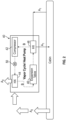
FIG. 2 is a schematic diagram of a vapor cooling system operably coupled to an air management system of an aircraft according to an embodiment; and -
FIG. 3 is a schematic diagram of a vapor cooling system operably coupled to one or more subsystems of an aircraft according to an embodiment. - A detailed description of one or more embodiments of the disclosed apparatus and method are presented herein by way of exemplification and not limitation with reference to the Figures.
- With reference now to
FIG. 1 , an example of schematic of anair management system 10 of a vehicle, such as anaircraft 11 is illustrated. As shown, the aircraft includes acabin 12 fluidly coupled to theair management system 10. In the illustrated, non-limiting embodiment, thecabin 12 is a compartment of an aircraft that includes an internal environment. For example,cabin 12 may be configured to house people, cargo, and the like therein. Theair management system 10 is configured to provide conditioned air to thecabin 12 as well as remove used or contaminated air from thecabin 12. Theair management system 10 includes anenvironmental control system 13 including at least one air conditioning unit orpack 14, and a cabindischarge air system 16. While theair management system 10 is illustrated and described herein with reference to anaircraft 11, it should be understood that the systems and techniques discussed herein may be used for a variety of ventilation systems. For example,cabin 12 may be replaced with any pressurized cabin. As such, systems described herein may be used with submarine ventilation systems, personnel carrier ventilation systems, bus ventilation systems, or any other ventilation system that may use pressurized air. - As shown in the
FIG. 1 , a medium, such as air for example, is provided from one ormore sources 18 to theair management system 10. Examples ofsuitable sources 18 include but are not limited to an engine of theaircraft 11, an auxiliary power unit of theaircraft 11, and fresh, outside air. The medium output from thesesources 18 is provided to the one or moreair conditioning units 14 of theenvironmental control system 13. Within theair conditioning units 14, the medium is conditioned. This conditioning includes altering one or more of a pressure, temperature, humidity, or flow rate of the medium based on an operating condition of the aircraft. The medium output or discharged from the one or moreair conditioning units 14 of theenvironmental control system 13 may be used to maintain a target range of pressures, temperatures, and/or humidity within thecabin 12. - The medium discharged from the
air conditioning units 14 is provided to an air mixing unit or mixingmanifold 20 via one ormore outlet ducts 22. Similarly, at least oneduct 24 of the cabindischarge air system 16 extends from thecabin 12 to theair mixing unit 20 to deliver air exhausted from thecabin 12 to theair mixing unit 20. Within theair mixing unit 20, the cabin recirculating air is mixed with the medium output from the one or moreair conditioning units 14 to achieve a mixed medium having one or more desired parameters, such as temperature, pressure, and humidity for example. - In an embodiment, the mixed medium is delivered to the
cabin 12 from theair mixing unit 20 via one ormore conduits 26. As shown, the mixed medium may be delivered to thecabin 12 via a ventilation system arranged near a ceiling of thecabin 12. In some embodiments, the mixed medium typically circulates from the top of thecabin 12 toward the floor and is distributed to a plurality ofindividual vents 28 of the ventilation system mounted spaced laterally between the front and rear of thecabin 12. It should be understood that theair management system 10 illustrated and described herein is intended as an example only, and that any suitable air management system is within the scope of the disclosure. - With continued reference to
FIG. 1 , and further reference toFIG. 2 , the temperature of the air collected within the cabindischarge air system 16 may be different than the temperature of the air provided to thecabin 12 from theair mixing unit 20. Accordingly, in some embodiments, the portion of the cabin air intended to be returned to theair mixing unit 20 via one ormore conduits 24, also referred to herein as "cabin recirculation air," may be conditioned at a location downstream from an outlet of thecabin 12 and upstream from theair mixing unit 20. In an embodiment, conditioning the cabin recirculation air includes cooling or heating the cabin recirculation air. - As shown in
FIG. 2 , a flow of a first medium A1, such as the cabin recirculation air for example, provided from a first subsystem of the vehicle, may be cooled by a cooling medium B within at least one heat exchanger. Unlike existing systems where the cabin recirculation air is conditioned within theenvironmental control system 13, in an embodiment, the cooling medium B is a fluid contained within a separate or secondaryvapor cooling system 40, such as having a closed loop vapor compression cycle for example. In such embodiments, thevapor cooling system 40 is thermally coupled to theair management system 10 at the at least one heat exchanger. - In
FIG. 2 , thevapor cooling system 40 includes acompressor 42, afirst heat exchanger 44, andexpansion valve 46, and asecond heat exchanger 48 arranged to form a closed fluid loop through which the cooling medium circulates. The cooling medium B may be any suitable fluid including refrigerant, or any other fluid having suitable thermodynamic properties for proper operation of a vapor compression cycle. Although not shown, thecompressor 42 may be operably coupled to an electric motor. However, in some embodiments, thecompressor 42 may be alternatively or additionally driven by energy from another source. For example, thecompressor 42 may be operably coupled to a turbine via a shaft and energy extracted within the turbine may be used to drive thecompressor 42. - The
vapor cooling system 40 may additionally include a reversingvalve 50 operable to selectively control the direction of flow of the cooling medium B in either a first direction or a second direction within the fluid loop, such as based on a temperature of the first medium A1 output from the first subsystem. In such embodiments, thevapor cooling system 40 may be considered a heat pump. Accordingly, when the reversingvalve 50 is in a first position, the cooling medium B is configured to flow from thecompressor 42 to thefirst heat exchanger 44, to theexpansion valve 46, to thesecond heat exchanger 48, as shown inFIG. 2 . In such a configuration, thefirst heat exchanger 44 is operable as a condenser or heat rejection heat exchanger and thesecond heat exchanger 48 is operable as an evaporator or a heat absorption heat exchanger. When the reversingvalve 50 is in a second position, the cooling medium B is configured to flow from thecompressor 42 to thesecond heat exchanger 48, to theexpansion valve 46, and to thefirst heat exchanger 44 in series. In such a configuration, thesecond heat exchanger 48 is operable as a condenser or heat rejection heat exchanger and thefirst heat exchanger 44 is operable as an evaporator or a heat absorption heat exchanger. - With continued reference to
FIG. 2 , in embodiments where the first medium A1, such as cabin recirculation air for example, has been heated within thecabin 12 and therefore needs to be cooled, the first medium A1 may be provided to a heat exchanger of thevapor cooling system 40, such as thesecond heat exchanger 48 operable as a heat absorption heat exchanger of thevapor cooling system 40. Accordingly, within thesecond heat exchanger 48, heat is configured to transfer from the first medium A1 to the cooling medium B. Similarly, when the first medium A1 needs to be heated, the position of the reversingvalve 50 may be adjusted such that thesecond heat exchanger 48 is configured as the heat rejecting heat exchanger. In such embodiments, within thesecond heat exchanger 48, heat from the cooling medium B is configured to transfer to the first medium A1. The conditioned first medium A1, for example, cabin recirculation air output from theheat exchanger 48 of thevapor cooling system 40 may be delivered to same first subsystem, or alternatively, to a different subsystem of the vehicle. For example, the conditioned first medium A1 provided at the outlet of thesecond heat exchanger 48 may be returned to theair mixing unit 20 as previously described, may be returned directly to thecabin 12, or alternatively, or additionally may be provided to another system of the vehicle, such as theenvironmental control system 13 for example. - To counteract the heat transfer that occurs at the
second heat exchanger 48 of thevapor cooling system 40, a second medium A2 provided from a second subsystem, is arranged in a heat transfer relationship with the cooling medium B at thefirst heat exchanger 44. In the illustrated, non-limiting embodiment ofFIG. 2 , the second medium A2 is a flow of cabin discharge air, which is air exhausted from the cabin and that would normally be discharged overboard from the aircraft. Accordingly, in an embodiment, the first medium A1 and the second medium A2 may both be provided from the same subsystem, such as thecabin discharge system 16 for example. In embodiments where the reversingvalve 50 is in a first position and thesecond heat exchanger 48 is configured as a heat absorption heat exchanger, heat is configured to transfer from the cooling medium B to the second medium A2. Similarly, when the reversingvalve 50 is in the second position and the second heat exchanger is configured as a heat rejection heat exchanger, the cooling medium B is configured to receive heat from the second medium A2. In embodiments where the second medium A2 is cabin discharge air, the conditioned second medium A2 output from thefirst heat exchanger 44 may be exhausted overboard, into the ambient or external atmosphere surrounding the vehicle. By using cabin discharge air, a secondary flow source, such as a fan for example, would not be required when the aircraft is at altitude because of the pressure differential of the cabin and the outside ambient pressure. Although cabin discharge air is illustrated and described herein as the second medium A2, it should be appreciated that embodiments where the second medium A2 is supplied from another available source of theaircraft 11 besides thecabin discharge system 16 are also within the scope of the disclosure. - In other embodiments, such as shown in
FIG. 3 for example, the first medium A1 to be conditioned by thevapor cooling system 40 may be provided from a source other than thecabin 12. Examples of suitable mediums include but are not limited to, a liquid or air flow from an electronics cooling subsystem, and air surface cooler heat exchanger, fuel, bleed air drawn from an engine or auxiliary power unit of the vehicle, and a flow of fresh or outside air. In the illustrated, non-limiting embodiment, the first medium A1 is the fluid of the electronics cooling subsystem and is provided to a heat exchanger of thevapor cooling system 40, such as thefirst heat exchanger 44 for example, to control the temperature of the fluid of the electronics cooling subsystem and therefore the electronics to be cooled by the electronics cooling subsystem. Accordingly, whether the first medium A1 needs to be warmed or cooled by thevapor cooling system 40 may depend on the external conditions of the ambient atmosphere. - In embodiments where the first medium A1 needs to be cooled by the
vapor cooling system 40, any suitable medium operable as a heat sink, including but not limited to cabin recirculation air, cabin exhaust air, fuel, and ram air, may be used as the second medium A2 provided to thesecond heat exchanger 48. By heating the first medium A1 of the electronics cooling subsystem, hard cold starts of the associated electronics may be reduced. Accordingly, to heat the first medium A1 at thevapor cooling system 40, thefirst heat exchanger 44 is operable as a condenser, such that heat from the cooling medium B is transferred to the first medium A1 at thefirst heat exchanger 44. During such operating conditions, any suitable medium provided from a second source and having excess heat to release may be provided to thesecond heat exchanger 48 as the second medium A2. - A system including a
vapor cooling system 40 operably coupled to one or more other systems of a vehicle, such as theair management system 10 of an aircraft for example, allows for energy recovery of a conditioned medium such as air prior to exhausting the conditioned air overboard. This recovered energy may be used to further condition another fluid flow, such as the first medium A1 for example, at thevapor cooling system 40. Further, the use of a heat pumpvapor cooling system 40 allows such a benefit to be achieved for both heating and cooling. - The term "about" is intended to include the degree of error associated with measurement of the particular quantity based upon the equipment available at the time of filing the application.
- The terminology used herein is for the purpose of describing particular embodiments only and is not intended to be limiting of the present disclosure. As used herein, the singular forms "a", "an" and "the" are intended to include the plural forms as well, unless the context clearly indicates otherwise. It will be further understood that the terms "comprises" and/or "comprising," when used in this specification, specify the presence of stated features, integers, steps, operations, elements, and/or components, but do not preclude the presence or addition of one or more other features, integers, steps, operations, element components, and/or groups thereof.
- While the present disclosure has been described with reference to an exemplary embodiment or embodiments, it will be understood by those skilled in the art that various changes may be made and equivalents may be substituted for elements thereof without departing from the scope of the present disclosure. In addition, many modifications may be made to adapt a particular situation or material to the teachings of the present disclosure without departing from the essential scope thereof. Therefore, it is intended that the present disclosure not be limited to the particular embodiment disclosed as the best mode contemplated for carrying out this present disclosure, but that the present disclosure will include all embodiments falling within the scope of the claims.
Claims (15)
- A vehicle system comprising:a first medium provided from a first subsystem;a vapor cooling system (40) having a closed loop vapor compression cycle through which a cooling medium circulates, the first subsystem being fluidly coupled to the vapor cooling system (40); anda second medium provided from a second subsystem, the second subsystem being fluidly coupled to the vapor cooling system (40).
- The vehicle system of claim 1, wherein the first subsystem is a cabin discharge air system, or wherein the first medium is cabin recirculation air.
- The vehicle system of any preceding claim, wherein the second subsystem is a cabin discharge air system, and optionally wherein the second medium is cabin discharge air.
- The vehicle system of any preceding claim, wherein the second subsystem is an electronics cooling subsystem.
- The vehicle system of any preceding claim, wherein the vapor cooling system (40) is a heat pump.
- The vehicle system of any preceding claim, wherein the vapor cooling system (40) further comprises a first heat exchanger (44) and a second heat exchanger (48), the first subsystem being fluidly coupled to the first heat exchanger (44) and the second subsystem being fluidly coupled to the second heat exchanger (48).
- The vehicle system of claim 6, wherein an outlet of the first heat exchanger (44) is fluidly coupled to a cabin of the vehicle such that a conditioned first medium output from the first heat exchanger (44) is provided to the cabin.
- The vehicle system of claim 6, wherein an outlet of the first heat exchanger (44) is fluidly coupled to an air mixing unit of the vehicle such that a conditioned first medium output from the first heat exchanger (44) is provided to the air mixing unit, or wherein an outlet of the first heat exchanger (44) is fluidly coupled to an environmental control system of the vehicle such that a conditioned first medium output from the first heat exchanger (44) is provided to the environmental control system.
- The vehicle system of claim 6, wherein an outlet of the first heat exchanger (44) is fluidly coupled to an atmosphere external to the vehicle.
- A method comprising:conditioning a first medium provided from a first subsystem of a vehicle at a vapor cooling system (40) to form a conditioned first medium, the vapor cooling system (40) including a closed-loop vapor compression cycle; andrecovering energy from a second medium provided from a second subsystem of the vehicle at the vapor cooling system (40), wherein the recovered energy is used to condition the first medium.
- The method of claim 10, wherein the vapor cooling system (40) includes a first heat exchanger (44) and a second heat exchanger (48) and conditioning the first medium occurs at the first heat exchanger (44) using a cooling medium and conditioning the second medium occurs at the second heat exchanger (48) using the cooling medium.
- The method of claim 11, further comprising reversing a direction of flow of the cooling medium based on a temperature of the first medium output from the first subsystem.
- The method of claim 10, 11 or 12, further comprising exhausting at least one of the first medium and the second medium overboard from the vapor cooling system (40).
- The method of any of claims 10 to 13, further comprising returning the conditioned first medium to a subsystem separate from the first subsystem, and/or further comprising returning the conditioned second medium to the second subsystem.
- The method of any of claims 10 to 14, wherein at least one the first subsystem and the second subsystem is a cabin discharge system, or wherein the second subsystem is an electronics cooling subsystem.
Applications Claiming Priority (1)
| Application Number | Priority Date | Filing Date | Title |
|---|---|---|---|
| US18/185,652 US20240308669A1 (en) | 2023-03-17 | 2023-03-17 | Energy recovery and thermal control utilizing heat pump |
Publications (1)
| Publication Number | Publication Date |
|---|---|
| EP4431397A1 true EP4431397A1 (en) | 2024-09-18 |
Family
ID=90366652
Family Applications (1)
| Application Number | Title | Priority Date | Filing Date |
|---|---|---|---|
| EP24164249.5A Pending EP4431397A1 (en) | 2023-03-17 | 2024-03-18 | Improved energy recovery and thermal control utilizing heat pump |
Country Status (2)
| Country | Link |
|---|---|
| US (1) | US20240308669A1 (en) |
| EP (1) | EP4431397A1 (en) |
Citations (9)
| Publication number | Priority date | Publication date | Assignee | Title |
|---|---|---|---|---|
| US4434624A (en) * | 1981-03-27 | 1984-03-06 | Lockheed Corporation | Energy-efficient all-electric ECS for aircraft |
| US5918472A (en) * | 1997-07-11 | 1999-07-06 | Alliedsignal Inc. | Air cycle environmental control system with vapor cycle system assisted condensation |
| JP4232033B2 (en) * | 2004-06-09 | 2009-03-04 | 株式会社島津製作所 | Air conditioner for aircraft |
| US9669936B1 (en) * | 2012-10-24 | 2017-06-06 | The Boeing Company | Aircraft air conditioning systems and methods |
| US20190070924A1 (en) * | 2017-09-07 | 2019-03-07 | Tesla, Inc. | Optimal source electric vehicle heat pump with extreme temperature heating capability and efficient thermal preconditioning |
| US20210122478A1 (en) * | 2019-10-28 | 2021-04-29 | The Boeing Company | Aircraft systems and related methods |
| CN113788148A (en) * | 2021-08-24 | 2021-12-14 | 中国航空工业集团公司金城南京机电液压工程研究中心 | Direct heat exchange type heat pump air conditioning system of lubricating oil waste heat source |
| WO2023154380A1 (en) * | 2022-02-09 | 2023-08-17 | Space Perspective Inc. | Vehicle cabin conditioning system |
| EP4282761A1 (en) * | 2022-05-23 | 2023-11-29 | Hamilton Sundstrand Corporation | Vapor compression system for aerospace applications |
Family Cites Families (18)
| Publication number | Priority date | Publication date | Assignee | Title |
|---|---|---|---|---|
| US2932176A (en) * | 1957-02-28 | 1960-04-12 | United Aircraft Corp | Cabin temperature control |
| US4430867A (en) * | 1981-08-24 | 1984-02-14 | United Technologies Corporation | Air cycle refrigeration system |
| US5086622A (en) * | 1990-08-17 | 1992-02-11 | United Technologies Corporation | Environmental control system condensing cycle |
| US5701755A (en) * | 1997-01-15 | 1997-12-30 | Sundstrand Corporation | Cooling of aircraft electronic heat loads |
| US6655168B2 (en) * | 2001-07-05 | 2003-12-02 | Shimadzu Corporation | Aircraft air conditioner |
| US7231778B2 (en) * | 2004-03-29 | 2007-06-19 | Be Intellectual Property, Inc. | Cooling system for a commercial aircraft galley |
| US7305842B1 (en) * | 2005-05-23 | 2007-12-11 | Peter Schiff | Environmental control system and method for an aircraft |
| US7216495B1 (en) * | 2006-03-02 | 2007-05-15 | Harrison Thomas D | Air conditioning system |
| DE102009039814A1 (en) * | 2009-09-02 | 2011-03-10 | Airbus Operations Gmbh | System and method for cooling at least one heat-generating device in an aircraft |
| DE102010021890A1 (en) * | 2010-05-28 | 2011-12-01 | Airbus Operations Gmbh | Air conditioning system for an aircraft with hybrid operation |
| DE102011118078B4 (en) * | 2011-11-04 | 2024-08-01 | Airbus Operations Gmbh | Heat exchanger, cooling system and method for operating a heat exchanger and a cooling system |
| US20130255289A1 (en) * | 2012-03-30 | 2013-10-03 | Hamilton Sundstrand Corporation | Flash tank eliminator |
| US9957052B2 (en) * | 2015-01-27 | 2018-05-01 | Honeywell International Inc. | Aircraft environmental control system that optimizes the proportion of outside air from engines, APU's, ground air sources and the recirculated cabin air to maintain occupant comfort and maximize fuel economy |
| US10023317B2 (en) * | 2015-06-23 | 2018-07-17 | The Boeing Company | Flight deck takeoff duct and trim air mix muff |
| US9896216B2 (en) * | 2016-06-01 | 2018-02-20 | Honeywell Limited | ECO mode ECS logic |
| US11820519B2 (en) * | 2018-09-04 | 2023-11-21 | Honeywell International Inc. | Air-driven vapor cycle refrigeration system |
| US11230384B2 (en) * | 2019-04-23 | 2022-01-25 | Joby Aero, Inc. | Vehicle cabin thermal management system and method |
| US12042764B2 (en) * | 2020-05-11 | 2024-07-23 | Hamilton Sundstrand Corporation | Aircraft air management systems for deactivating contaminants |
-
2023
- 2023-03-17 US US18/185,652 patent/US20240308669A1/en active Pending
-
2024
- 2024-03-18 EP EP24164249.5A patent/EP4431397A1/en active Pending
Patent Citations (9)
| Publication number | Priority date | Publication date | Assignee | Title |
|---|---|---|---|---|
| US4434624A (en) * | 1981-03-27 | 1984-03-06 | Lockheed Corporation | Energy-efficient all-electric ECS for aircraft |
| US5918472A (en) * | 1997-07-11 | 1999-07-06 | Alliedsignal Inc. | Air cycle environmental control system with vapor cycle system assisted condensation |
| JP4232033B2 (en) * | 2004-06-09 | 2009-03-04 | 株式会社島津製作所 | Air conditioner for aircraft |
| US9669936B1 (en) * | 2012-10-24 | 2017-06-06 | The Boeing Company | Aircraft air conditioning systems and methods |
| US20190070924A1 (en) * | 2017-09-07 | 2019-03-07 | Tesla, Inc. | Optimal source electric vehicle heat pump with extreme temperature heating capability and efficient thermal preconditioning |
| US20210122478A1 (en) * | 2019-10-28 | 2021-04-29 | The Boeing Company | Aircraft systems and related methods |
| CN113788148A (en) * | 2021-08-24 | 2021-12-14 | 中国航空工业集团公司金城南京机电液压工程研究中心 | Direct heat exchange type heat pump air conditioning system of lubricating oil waste heat source |
| WO2023154380A1 (en) * | 2022-02-09 | 2023-08-17 | Space Perspective Inc. | Vehicle cabin conditioning system |
| EP4282761A1 (en) * | 2022-05-23 | 2023-11-29 | Hamilton Sundstrand Corporation | Vapor compression system for aerospace applications |
Also Published As
| Publication number | Publication date |
|---|---|
| US20240308669A1 (en) | 2024-09-19 |
Similar Documents
| Publication | Publication Date | Title |
|---|---|---|
| US4334411A (en) | Unique air cycle refrigeration system | |
| CN103079956B (en) | Aircraft air-conditioning system including the kind of refrigeration cycle separated | |
| EP1979232B1 (en) | Air conditioning arrangement for an aircraft with a plurality of climate zones that may be individually temperature-controlled | |
| US20100084118A1 (en) | Cooling system for aircraft electric or electronic devices | |
| EP3620378B1 (en) | Air-driven vapor cycle refrigeration system | |
| EP4292937B1 (en) | Ram air turbine powered cabin air compressor | |
| EP2735510B1 (en) | Aircraft air conditioning system and method of operating an aircraft air conditioning system | |
| US20240308669A1 (en) | Energy recovery and thermal control utilizing heat pump | |
| US20240410625A1 (en) | Regeneration using liquid loop of environmental control system | |
| EP4242107A1 (en) | Cooling system for vehicle | |
| EP4269246B1 (en) | Trim module with thermoelectric cooler | |
| EP4265521B1 (en) | Environmental control system with air powered pump | |
| EP4455011A2 (en) | Hybrid environmental control system for split cooling | |
| US12337975B2 (en) | Low pressure air cycle | |
| EP4428003A1 (en) | Hyperloop environmental control system | |
| US12459548B2 (en) | Hyperloop environmental control system | |
| EP4299444A1 (en) | Split regeneration environmental control system | |
| EP4725840A1 (en) | Low pressure air cycle environmental control system | |
| EP4509407A1 (en) | Air conditioning and vapor cycle system | |
| US12522259B2 (en) | Hyperloop environmental control system | |
| US20240300549A1 (en) | Hyperloop environmental control system |
Legal Events
| Date | Code | Title | Description |
|---|---|---|---|
| PUAI | Public reference made under article 153(3) epc to a published international application that has entered the european phase |
Free format text: ORIGINAL CODE: 0009012 |
|
| STAA | Information on the status of an ep patent application or granted ep patent |
Free format text: STATUS: THE APPLICATION HAS BEEN PUBLISHED |
|
| AK | Designated contracting states |
Kind code of ref document: A1 Designated state(s): AL AT BE BG CH CY CZ DE DK EE ES FI FR GB GR HR HU IE IS IT LI LT LU LV MC ME MK MT NL NO PL PT RO RS SE SI SK SM TR |
|
| STAA | Information on the status of an ep patent application or granted ep patent |
Free format text: STATUS: REQUEST FOR EXAMINATION WAS MADE |
|
| 17P | Request for examination filed |
Effective date: 20250318 |
|
| STAA | Information on the status of an ep patent application or granted ep patent |
Free format text: STATUS: EXAMINATION IS IN PROGRESS |
|
| 17Q | First examination report despatched |
Effective date: 20251020 |