EP4431390A1 - System including stowable tablet holder apparatus - Google Patents
System including stowable tablet holder apparatus Download PDFInfo
- Publication number
- EP4431390A1 EP4431390A1 EP24164136.4A EP24164136A EP4431390A1 EP 4431390 A1 EP4431390 A1 EP 4431390A1 EP 24164136 A EP24164136 A EP 24164136A EP 4431390 A1 EP4431390 A1 EP 4431390A1
- Authority
- EP
- European Patent Office
- Prior art keywords
- support arm
- pivotable support
- tablet
- stowable
- base member
- Prior art date
- Legal status (The legal status is an assumption and is not a legal conclusion. Google has not performed a legal analysis and makes no representation as to the accuracy of the status listed.)
- Pending
Links
Images







Classifications
-
- B—PERFORMING OPERATIONS; TRANSPORTING
- B64—AIRCRAFT; AVIATION; COSMONAUTICS
- B64D—EQUIPMENT FOR FITTING IN OR TO AIRCRAFT; FLIGHT SUITS; PARACHUTES; ARRANGEMENT OR MOUNTING OF POWER PLANTS OR PROPULSION TRANSMISSIONS IN AIRCRAFT
- B64D11/00—Passenger or crew accommodation; Flight-deck installations not otherwise provided for
- B64D11/0015—Arrangements for entertainment or communications, e.g. radio, television
- B64D11/00152—Seat back fixtures for removable monitors, e.g. tablet computers
-
- B—PERFORMING OPERATIONS; TRANSPORTING
- B64—AIRCRAFT; AVIATION; COSMONAUTICS
- B64D—EQUIPMENT FOR FITTING IN OR TO AIRCRAFT; FLIGHT SUITS; PARACHUTES; ARRANGEMENT OR MOUNTING OF POWER PLANTS OR PROPULSION TRANSMISSIONS IN AIRCRAFT
- B64D11/00—Passenger or crew accommodation; Flight-deck installations not otherwise provided for
- B64D11/0015—Arrangements for entertainment or communications, e.g. radio, television
- B64D11/00155—Individual entertainment or communication system remote controls therefor, located in or connected to seat components, e.g. to seat back or arm rest
-
- B—PERFORMING OPERATIONS; TRANSPORTING
- B64—AIRCRAFT; AVIATION; COSMONAUTICS
- B64D—EQUIPMENT FOR FITTING IN OR TO AIRCRAFT; FLIGHT SUITS; PARACHUTES; ARRANGEMENT OR MOUNTING OF POWER PLANTS OR PROPULSION TRANSMISSIONS IN AIRCRAFT
- B64D11/00—Passenger or crew accommodation; Flight-deck installations not otherwise provided for
- B64D11/06—Arrangements of seats, or adaptations or details specially adapted for aircraft seats
- B64D11/0638—Arrangements of seats, or adaptations or details specially adapted for aircraft seats with foldable tables, trays or cup holders
Definitions
- inventions of the inventive concepts disclosed herein are directed to a system.
- the system includes a structure and a stowable tablet holder apparatus installed in an aircraft.
- the stowable tablet holder apparatus may include a pivotable support arm and a base member.
- the base member may have a rear portion and a front lip portion.
- the base member may be horizontally positioned when in a stowed state and when in a deployed state.
- the base member may horizontally stow within the structure in the stowed state.
- the base member may at least partially extend horizontally from the structure in the deployed state such that the front lip portion and optionally part of the rear portion extend horizontally away from the structure.
- a front of the rear portion may be configured to connect to the pivotable support arm.
- the pivotable support arm may be connected to the front of the rear portion.
- the pivotable support arm may extend from the front of the rear portion toward the front lip portion when in the stowed state.
- the stowable tablet holder apparatus may be configured to hold a tablet at a viewing angle by rotation of the pivotable support arm such that a bottom edge of the tablet rests against the front lip portion and a back of the tablet rests against the pivotable support arm.
- inventive concepts are not limited in their application to the details of construction and the arrangement of the components or steps or methodologies set forth in the following description or illustrated in the drawings.
- inventive concepts disclosed herein may be practiced without these specific details.
- well-known features may not be described in detail to avoid unnecessarily complicating the instant disclosure.
- inventive concepts disclosed herein are capable of other embodiments or of being practiced or carried out in various ways. Also, it is to be understood that the phraseology and terminology employed herein is for the purpose of description and should not be regarded as limiting.
- a letter following a reference numeral is intended to reference an embodiment of the feature or element that may be similar, but not necessarily identical, to a previously described element or feature bearing the same reference numeral (e.g., 1, 1a, 1b).
- reference numeral e.g. 1, 1a, 1b
- Such shorthand notations are used for purposes of convenience only, and should not be construed to limit the inventive concepts disclosed herein in any way unless expressly stated to the contrary.
- any reference to "one embodiment,” or “some embodiments” means that a particular element, feature, structure, or characteristic described in connection with the embodiment is included in at least one embodiment of the inventive concepts disclosed herein.
- the appearances of the phrase “in some embodiments” in various places in the specification are not necessarily all referring to the same embodiment, and embodiments of the inventive concepts disclosed may include one or more of the features expressly described or inherently present herein, or any combination of sub-combination of two or more such features, along with any other features which may not necessarily be expressly described or inherently present in the instant disclosure.
- inventions of the inventive concepts disclosed herein are directed to a system including a stowable tablet holder apparatus.
- the system may be a non-vehicular system or may include a vehicle (e.g., aircraft, watercraft, automobile, train, etc.).
- the stowable tablet holder apparatus may be used in any suitable environment.
- the stowable tablet holder apparatus can secure a tablet at a height that allows a comfortable viewing angle and can also be used while reclined or in a bed position.
- a stowable tablet holder apparatus can be stored horizontally in a structure (e.g., a wall or a business class seat furniture, such as in wall of the furniture under an in-flight entertainment (IFE) display).
- the stowable tablet holder apparatus may slide out towards the passenger to create a shelf where a tablet or smartphone can rest.
- a pivotable support arm can be deployed from this shelf to stop the tablet from falling and hold the tablet in place at a specific angle. This pivotable support arm may be held at different angles to adjust an orientation of the tablet and place the tablet at an optimal viewing angle for different sized passengers.
- the stowable tablet holder apparatus may allow passengers to secure their devices at a location that provides a comfortable viewing angle. In some embodiments, the stowable tablet holder apparatus may provide angle adjustment to allow different sized passengers to find their optimal viewing angle. Some embodiments may allow a tablet holder feature to be removed from the meal table, so passengers can use the meal table for a meal or store it away while still being able to enjoy their content on a tablet held in place by the stowable tablet holder apparatus. In some embodiments, the stowable tablet holder apparatus can be deployed and controlled using different means, so it can scale to the needs of different airlines.
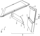
- FIG. 1 an exemplary embodiment of a system 100 including a vehicle (e.g., aircraft 102, watercraft, automobile, train, etc.) including a tablet 104 and an exploded view of a stowable tablet holder apparatus 106 are depicted according to the inventive concepts.
- the stowable tablet holder apparatus 106 may be installed in the aircraft 102.
- the stowable tablet holder apparatus 106 may include a support arm (e.g., a pivotable support arm 108) and a base member 114.
- the base member 114 may have a rear portion 116, a front lip portion 120, and optionally a recessed portion 118.
- the base member 114 may be horizontally positioned when in a stowed state and when in a deployed state.
- the base member 114 may horizontally stow within a structure in the stowed state.
- the base member 114 may at least partially extend horizontally from the structure in the deployed state such that the recessed portion 118, the front lip portion 120, and part of the rear portion 160 extend horizontally away from the structure.
- a vertical thickness of the rear portion 116 is greater than a vertical thickness of the recessed portion 118.
- a vertical thickness of the front lip portion 120 is greater than a vertical thickness of the recessed portion 118.
- a front of the rear portion 116 may be configured to connect to the pivotable support arm 108.
- the pivotable support arm 108 may be connected to the front of the rear portion 116 via at least one friction hinge 110, such as via pins 112.
- each of the at least one friction hinge 110 has a pin 112 connecting the pivotable support arm 108 to the rear portion 114.
- the pivotable support arm 108 may abut the recessed portion 118 when the base member 114 is in the stowed state.
- the pivotable support arm 108 may extend from the front of the rear portion 116 toward the front lip portion 120 when in the stowed state.
- the pivotable support arm 108 may be configured to pivot about a horizontal axis (e.g., extending between the pins 112) via the at least one friction hinge 110 such that the pivotable support arm 108 has a range of motion between a horizontal position abutting the recessed portion 118 and a terminal rotation position (e.g., a maximum amount of rotation away from the recessed portion 118).
- the pivotable support arm 108 may have a curved front surface 113.
- the pivotable support arm 108 may extend from the front of the rear portion 116 toward the curved front surface 113.
- a bottom edge of the curved front surface 113 may be closer to the rear portion 116 than a top edge of the curved front surface 113.
- an angle between a top surface of the recessed portion 118 and a rear surface of the front lip portion 120 may be acute to accommodate a bottom edge of a tilted tablet 104.
- the stowable tablet holder apparatus 106 may be configured to hold a tablet 104 at any of various viewing angles by rotation of the pivotable support arm to a desired position such that a bottom edge of the tablet 104 rests on the recessed portion 118 and against the front lip portion 120 and a back of the tablet rests against a portion of the curved front surface 113 of the pivotable support arm 108.
- the pivotable support arm 108 has at least a 90-degree range of motion.
- the pivotable support arm 108 has at least a 100-degree range of motion.
- the pivotable support arm 108 has less than a 90-degree range of motion.
- a top surface of the pivotable support arm 108 may be flat and a bottom surface of the pivotable support arm 108 may be flat. In some embodiments, a bottom surface of the base member 114 may be flat.
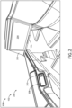
- the aircraft 102 may include a passenger suite 200.
- the passenger suite 102 may include a structure (e.g., a wall 202 of the passenger suite 200), an in-flight entertainment 204 display (e.g., installed on the wall 202), the stowable tablet holder apparatus 106 installed in the structure (e.g., the wall 202), a passenger seat 206, and/or a user interface system (e.g., a touchscreen display 208 and/or buttons 210), some or all of which may be communicatively coupled at any given time.
- a structure e.g., a wall 202 of the passenger suite 200
- an in-flight entertainment 204 display e.g., installed on the wall 202
- the stowable tablet holder apparatus 106 installed in the structure (e.g., the wall 202)
- a passenger seat 206 e.g., a passenger seat 206
- a user interface system e.g., a touchscreen display 208 and
- the base member 114 of the stowable tablet holder apparatus 106 is positioned in a stowed state, horizontally stowed within the structure.
- the stowable tablet holder apparatus 106 may be installed below the IFE display 204, though in other embodiments, the stowable tablet holder apparatus 106 may be installed at any suitable location.
- the base member 114 of the stowable tablet holder apparatus 106 is positioned in a deployed state.
- the base member 114 may at least partially extends horizontally from the structure in the deployed state such that the recessed portion 118, the front lip portion 120, and part of the rear portion 116 extend horizontally away from the structure (e.g., the wall 202).
- FIG. 4 an exemplary embodiment of the system 100 of FIGS. 1-3 is shown.
- the base member 114 of the stowable tablet holder apparatus 106 is positioned in a deployed state, and the pivotable support arm 108 may be configured to pivot about a horizontal axis (e.g., extending between the pins 112) via the at least one friction hinge 110 such that the pivotable support arm 108 has a range of motion between a horizontal position abutting the recessed portion 118 and a terminal rotation position (e.g., a maximum amount of rotation away from the recessed portion 118).
- a horizontal axis e.g., extending between the pins 112
- a terminal rotation position e.g., a maximum amount of rotation away from the recessed portion 118.
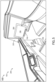
- the base member 114 of the stowable tablet holder apparatus 106 is positioned in a deployed state.
- the stowable tablet holder apparatus 106 may be configured to hold a tablet 104 at any of various viewing angles by rotation of the pivotable support arm to a desired position such that a bottom edge of the tablet 104 rests on the recessed portion 118 and against the front lip portion 120 and a back of the tablet rests against a portion of the curved front surface 113 of the pivotable support arm 108.
- FIG. 6 an exemplary embodiment of the system 100 of FIGS. 1-5 is shown.
- the base member 114 of the stowable tablet holder apparatus 106 is positioned in a stowed state, horizontally stowed within the structure.
- FIG. 7 an exemplary embodiment of the system 100 of FIGS. 1-6 is shown. As shown in FIG. 7 , the base member 114 of the stowable tablet holder apparatus 106 is positioned in a deployed state.
- the base member 114 of the stowable tablet holder apparatus 106 is positioned in a deployed state.
- the stowable tablet holder apparatus 106 may be configured to hold a tablet 104 at any of various viewing angles by rotation of the pivotable support arm 108 to a desired position such that a bottom edge of the tablet 104 rests on the recessed portion 118 and against the front lip portion 120 and a back of the tablet rests against a portion of the curved front surface 113 of the pivotable support arm 108.
- the stowable tablet holder apparatus 106 may include a push-to-deploy mechanism, which for example may include a spring and a latch.
- the stowable tablet holder apparatus 106 may be manually deployable and stowable.
- the stowable tablet holder apparatus 106 may be manually deployable and stowable by a pressing against a front of the front lip portion 120.
- the stowable tablet holder apparatus 106 may be manually deployable and stowable by a pulling a front of the front lip portion 120.
- the stowable tablet holder apparatus 106 may be motorized to move the base member 114 between the stowed state and the deployed state.
- a passenger 1202 may interface with the user interface system (e.g., which may include at least one button 210 and/or a touchscreen display 208) configured to activate a motorized action of the stowable tablet holder apparatus 106 to move between the stowed state and the deployed state.
- the user interface system e.g., which may include at least one button 210 and/or a touchscreen display 208
- embodiments of the inventive concepts disclosed herein may be directed to a system including a stowable tablet holder apparatus.
- At least one means one or a plurality of; for example, “at least one” may comprise one, two, three, ..., one hundred, or more.
- one or more means one or a plurality of; for example, “one or more” may comprise one, two, three, ..., one hundred, or more.
- zero or more means zero, one, or a plurality of; for example, “zero or more” may comprise zero, one, two, three, ..., one hundred, or more.
- the methods, operations, and/or functionality disclosed may be implemented as sets of instructions or software readable by a device. Further, it is understood that the specific order or hierarchy of steps in the methods, operations, and/or functionality disclosed are examples of exemplary approaches. Based upon design preferences, it is understood that the specific order or hierarchy of steps in the methods, operations, and/or functionality can be rearranged while remaining within the scope of the inventive concepts disclosed herein.
- the accompanying claims may present elements of the various steps in a sample order, and are not necessarily meant to be limited to the specific order or hierarchy presented.
- embodiments of the methods according to the inventive concepts disclosed herein may include one or more of the steps described herein. Further, such steps may be carried out in any desired order and two or more of the steps may be carried out simultaneously with one another. Two or more of the steps disclosed herein may be combined in a single step, and in some embodiments, one or more of the steps may be carried out as two or more sub-steps. Further, other steps or sub-steps may be carried in addition to, or as substitutes to one or more of the steps disclosed herein.
- inventive concepts disclosed herein are well adapted to carry out the objects and to attain the advantages mentioned herein as well as those inherent in the inventive concepts disclosed herein. While presently preferred embodiments of the inventive concepts disclosed herein have been described for purposes of this disclosure, it will be understood that numerous changes may be made which will readily suggest themselves to those skilled in the art and which are accomplished within the broad scope and coverage of the inventive concepts disclosed and claimed herein.
Landscapes
- Engineering & Computer Science (AREA)
- Aviation & Aerospace Engineering (AREA)
- Fittings On The Vehicle Exterior For Carrying Loads, And Devices For Holding Or Mounting Articles (AREA)
Abstract
Description
- Use of personal electronic devices, such as tablets, by airplane passengers is a growing trend. Passengers prepare for flights by downloading content from streaming platforms and they expect to be able to enjoy this content during their flight, therefore they expect the seat to have an area where tablets or smartphones can be secured while viewing content.
- Current business class seat products incorporate tablet holders in the meal table; however, the height of meal tables is optimized for eating and may be too low to provide a comfortable viewing angle. Furthermore, the height of some meal tables makes them unsuitable for being used when the seat is in a recline or deep recline position, so a passenger is not able to watch content on their devices comfortably while in a reclined position.
- In one aspect, embodiments of the inventive concepts disclosed herein are directed to a system. The system includes a structure and a stowable tablet holder apparatus installed in an aircraft. The stowable tablet holder apparatus may include a pivotable support arm and a base member. The base member may have a rear portion and a front lip portion. The base member may be horizontally positioned when in a stowed state and when in a deployed state. The base member may horizontally stow within the structure in the stowed state. The base member may at least partially extend horizontally from the structure in the deployed state such that the front lip portion and optionally part of the rear portion extend horizontally away from the structure. A front of the rear portion may be configured to connect to the pivotable support arm. The pivotable support arm may be connected to the front of the rear portion. The pivotable support arm may extend from the front of the rear portion toward the front lip portion when in the stowed state. When the base member is in the deployed state, the stowable tablet holder apparatus may be configured to hold a tablet at a viewing angle by rotation of the pivotable support arm such that a bottom edge of the tablet rests against the front lip portion and a back of the tablet rests against the pivotable support arm.
- Implementations of the inventive concepts disclosed herein may be better understood when consideration is given to the following detailed description thereof. Such description makes reference to the included drawings, which are not necessarily to scale, and in which some features may be exaggerated and some features may be omitted or may be represented schematically in the interest of clarity. Like reference numerals in the drawings may represent and refer to the same or similar element, feature, or function. In the drawings:
-
FIG. 1 is a view of an exemplary embodiment of a system including a vehicle including a tablet and an exploded view of a stowable tablet holder apparatus according to the inventive concepts disclosed herein. -
FIGS. 2-10 are views of an exemplary embodiment of the system ofFIG. 1 according to the inventive concepts disclosed herein. -
FIG. 11 is a view of an exemplary embodiment of the system ofFIGS. 1-10 according to the inventive concepts disclosed herein. -
FIGS. 12A and12B are views of an exemplary embodiment of the system ofFIGS. 1-10 according to the inventive concepts disclosed herein. -
FIGS. 13A and13B are views of an exemplary embodiment of the system ofFIGS. 1-10 according to the inventive concepts disclosed herein. - Before explaining at least one embodiment of the inventive concepts disclosed herein in detail, it is to be understood that the inventive concepts are not limited in their application to the details of construction and the arrangement of the components or steps or methodologies set forth in the following description or illustrated in the drawings. In the following detailed description of embodiments of the instant inventive concepts, numerous specific details are set forth in order to provide a more thorough understanding of the inventive concepts. However, it will be apparent to one of ordinary skill in the art having the benefit of the instant disclosure that the inventive concepts disclosed herein may be practiced without these specific details. In other instances, well-known features may not be described in detail to avoid unnecessarily complicating the instant disclosure. The inventive concepts disclosed herein are capable of other embodiments or of being practiced or carried out in various ways. Also, it is to be understood that the phraseology and terminology employed herein is for the purpose of description and should not be regarded as limiting.
- As used herein a letter following a reference numeral is intended to reference an embodiment of the feature or element that may be similar, but not necessarily identical, to a previously described element or feature bearing the same reference numeral (e.g., 1, 1a, 1b). Such shorthand notations are used for purposes of convenience only, and should not be construed to limit the inventive concepts disclosed herein in any way unless expressly stated to the contrary.
- Further, unless expressly stated to the contrary, "or" refers to an inclusive or and not to an exclusive or. For example, a condition A or B is satisfied by anyone of the following: A is true (or present) and B is false (or not present), A is false (or not present) and B is true (or present), and both A and B are true (or present).
- In addition, use of the "a" or "an" are employed to describe elements and components of embodiments of the instant inventive concepts. This is done merely for convenience and to give a general sense of the inventive concepts, and "a" and "an" are intended to include one or at least one and the singular also includes the plural unless it is obvious that it is meant otherwise.
- Finally, as used herein any reference to "one embodiment," or "some embodiments" means that a particular element, feature, structure, or characteristic described in connection with the embodiment is included in at least one embodiment of the inventive concepts disclosed herein. The appearances of the phrase "in some embodiments" in various places in the specification are not necessarily all referring to the same embodiment, and embodiments of the inventive concepts disclosed may include one or more of the features expressly described or inherently present herein, or any combination of sub-combination of two or more such features, along with any other features which may not necessarily be expressly described or inherently present in the instant disclosure.
- Broadly, embodiments of the inventive concepts disclosed herein are directed to a system including a stowable tablet holder apparatus. The system may be a non-vehicular system or may include a vehicle (e.g., aircraft, watercraft, automobile, train, etc.). The stowable tablet holder apparatus may be used in any suitable environment. In some embodiments, the stowable tablet holder apparatus can secure a tablet at a height that allows a comfortable viewing angle and can also be used while reclined or in a bed position.
- In some embodiments, a stowable tablet holder apparatus can be stored horizontally in a structure (e.g., a wall or a business class seat furniture, such as in wall of the furniture under an in-flight entertainment (IFE) display). The stowable tablet holder apparatus may slide out towards the passenger to create a shelf where a tablet or smartphone can rest. A pivotable support arm can be deployed from this shelf to stop the tablet from falling and hold the tablet in place at a specific angle. This pivotable support arm may be held at different angles to adjust an orientation of the tablet and place the tablet at an optimal viewing angle for different sized passengers.
- In some embodiments, the stowable tablet holder apparatus may allow passengers to secure their devices at a location that provides a comfortable viewing angle. In some embodiments, the stowable tablet holder apparatus may provide angle adjustment to allow different sized passengers to find their optimal viewing angle. Some embodiments may allow a tablet holder feature to be removed from the meal table, so passengers can use the meal table for a meal or store it away while still being able to enjoy their content on a tablet held in place by the stowable tablet holder apparatus. In some embodiments, the stowable tablet holder apparatus can be deployed and controlled using different means, so it can scale to the needs of different airlines.
- Referring now to
FIG. 1 , an exemplary embodiment of asystem 100 including a vehicle (e.g.,aircraft 102, watercraft, automobile, train, etc.) including atablet 104 and an exploded view of a stowabletablet holder apparatus 106 are depicted according to the inventive concepts. For example, the stowabletablet holder apparatus 106 may be installed in theaircraft 102. In some embodiments, the stowabletablet holder apparatus 106 may include a support arm (e.g., a pivotable support arm 108) and abase member 114. - For example, the
base member 114 may have arear portion 116, afront lip portion 120, and optionally a recessedportion 118. Thebase member 114 may be horizontally positioned when in a stowed state and when in a deployed state. Thebase member 114 may horizontally stow within a structure in the stowed state. For example, thebase member 114 may at least partially extend horizontally from the structure in the deployed state such that therecessed portion 118, thefront lip portion 120, and part of the rear portion 160 extend horizontally away from the structure. In some embodiments, a vertical thickness of therear portion 116 is greater than a vertical thickness of therecessed portion 118. In some embodiments, a vertical thickness of thefront lip portion 120 is greater than a vertical thickness of therecessed portion 118. A front of therear portion 116 may be configured to connect to thepivotable support arm 108. - For example, the
pivotable support arm 108 may be connected to the front of therear portion 116 via at least onefriction hinge 110, such as via pins 112. In some embodiments, each of the at least onefriction hinge 110 has apin 112 connecting thepivotable support arm 108 to therear portion 114. Thepivotable support arm 108 may abut the recessedportion 118 when thebase member 114 is in the stowed state. Thepivotable support arm 108 may extend from the front of therear portion 116 toward thefront lip portion 120 when in the stowed state. Thepivotable support arm 108 may be configured to pivot about a horizontal axis (e.g., extending between the pins 112) via the at least onefriction hinge 110 such that thepivotable support arm 108 has a range of motion between a horizontal position abutting the recessedportion 118 and a terminal rotation position (e.g., a maximum amount of rotation away from the recessed portion 118). Thepivotable support arm 108 may have a curvedfront surface 113. Thepivotable support arm 108 may extend from the front of therear portion 116 toward the curvedfront surface 113. In some embodiments, when thebase member 114 is horizontally positioned in the stowed state, a bottom edge of the curvedfront surface 113 may be closer to therear portion 116 than a top edge of the curvedfront surface 113. In some embodiments, an angle between a top surface of the recessedportion 118 and a rear surface of thefront lip portion 120 may be acute to accommodate a bottom edge of a tiltedtablet 104. - When the
base member 114 is in the deployed state, the stowabletablet holder apparatus 106 may be configured to hold atablet 104 at any of various viewing angles by rotation of the pivotable support arm to a desired position such that a bottom edge of thetablet 104 rests on the recessedportion 118 and against thefront lip portion 120 and a back of the tablet rests against a portion of the curvedfront surface 113 of thepivotable support arm 108. In some embodiments, thepivotable support arm 108 has at least a 90-degree range of motion. In some embodiments, thepivotable support arm 108 has at least a 100-degree range of motion. In some embodiments, thepivotable support arm 108 has less than a 90-degree range of motion. - In some embodiments, when the
pivotable support arm 108 abuts the recessedportion 118, a top surface of thepivotable support arm 108 may be flat and a bottom surface of thepivotable support arm 108 may be flat. In some embodiments, a bottom surface of thebase member 114 may be flat. - Referring now to
FIG. 2 , an exemplary embodiment of thesystem 100 ofFIG. 1 is shown. For example, theaircraft 102 may include apassenger suite 200. Thepassenger suite 102 may include a structure (e.g., awall 202 of the passenger suite 200), an in-flight entertainment 204 display (e.g., installed on the wall 202), the stowabletablet holder apparatus 106 installed in the structure (e.g., the wall 202), apassenger seat 206, and/or a user interface system (e.g., atouchscreen display 208 and/or buttons 210), some or all of which may be communicatively coupled at any given time. As shown inFIG. 2 , thebase member 114 of the stowabletablet holder apparatus 106 is positioned in a stowed state, horizontally stowed within the structure. In some embodiments, the stowabletablet holder apparatus 106 may be installed below theIFE display 204, though in other embodiments, the stowabletablet holder apparatus 106 may be installed at any suitable location. - Referring now to
FIG. 3 , an exemplary embodiment of thesystem 100 ofFIGS. 1-2 is shown. As shown inFIG. 3 , thebase member 114 of the stowabletablet holder apparatus 106 is positioned in a deployed state. Thebase member 114 may at least partially extends horizontally from the structure in the deployed state such that the recessedportion 118, thefront lip portion 120, and part of therear portion 116 extend horizontally away from the structure (e.g., the wall 202). - Referring now to
FIG. 4 , an exemplary embodiment of thesystem 100 ofFIGS. 1-3 is shown. As shown inFIG. 4 , thebase member 114 of the stowabletablet holder apparatus 106 is positioned in a deployed state, and thepivotable support arm 108 may be configured to pivot about a horizontal axis (e.g., extending between the pins 112) via the at least onefriction hinge 110 such that thepivotable support arm 108 has a range of motion between a horizontal position abutting the recessedportion 118 and a terminal rotation position (e.g., a maximum amount of rotation away from the recessed portion 118). - Referring now to
FIG. 5 , an exemplary embodiment of thesystem 100 ofFIGS. 1-4 is shown. As shown inFIG. 5 , thebase member 114 of the stowabletablet holder apparatus 106 is positioned in a deployed state. When thebase member 114 is in the deployed state, the stowabletablet holder apparatus 106 may be configured to hold atablet 104 at any of various viewing angles by rotation of the pivotable support arm to a desired position such that a bottom edge of thetablet 104 rests on the recessedportion 118 and against thefront lip portion 120 and a back of the tablet rests against a portion of the curvedfront surface 113 of thepivotable support arm 108. - Referring now to
FIG. 6 , an exemplary embodiment of thesystem 100 ofFIGS. 1-5 is shown. As shown inFIG. 6 , thebase member 114 of the stowabletablet holder apparatus 106 is positioned in a stowed state, horizontally stowed within the structure. - Referring now to
FIG. 7 , an exemplary embodiment of thesystem 100 ofFIGS. 1-6 is shown. As shown inFIG. 7 , thebase member 114 of the stowabletablet holder apparatus 106 is positioned in a deployed state. - Referring now to
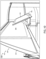
FIGS. 8-10 , an exemplary embodiment of thesystem 100 ofFIGS. 1-7 is shown. As shown inFIGS. 8-10 , thebase member 114 of the stowabletablet holder apparatus 106 is positioned in a deployed state. When thebase member 114 is in the deployed state, the stowabletablet holder apparatus 106 may be configured to hold atablet 104 at any of various viewing angles by rotation of thepivotable support arm 108 to a desired position such that a bottom edge of thetablet 104 rests on the recessedportion 118 and against thefront lip portion 120 and a back of the tablet rests against a portion of the curvedfront surface 113 of thepivotable support arm 108. - Referring now to
FIGS. 11 ,12A , and12B , an exemplary embodiment of thesystem 100 ofFIGS. 1-10 is shown. As shown inFIGS. 11 ,12A , and12B , the stowabletablet holder apparatus 106 may include a push-to-deploy mechanism, which for example may include a spring and a latch. For example, the stowabletablet holder apparatus 106 may be manually deployable and stowable. For example, the stowabletablet holder apparatus 106 may be manually deployable and stowable by a pressing against a front of thefront lip portion 120. In some embodiments, the stowabletablet holder apparatus 106 may be manually deployable and stowable by a pulling a front of thefront lip portion 120. - Referring now to
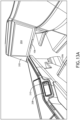
FIGS. 13A and13B , an exemplary embodiment of thesystem 100 ofFIGS. 1-10 is shown. As shown inFIGS. 13A and13B , the stowabletablet holder apparatus 106 may be motorized to move thebase member 114 between the stowed state and the deployed state. For example, a passenger 1202 may interface with the user interface system (e.g., which may include at least onebutton 210 and/or a touchscreen display 208) configured to activate a motorized action of the stowabletablet holder apparatus 106 to move between the stowed state and the deployed state. - As will be appreciated from the above, embodiments of the inventive concepts disclosed herein may be directed to a system including a stowable tablet holder apparatus.
- As used throughout, "at least one" means one or a plurality of; for example, "at least one" may comprise one, two, three, ..., one hundred, or more. Similarly, as used throughout, "one or more" means one or a plurality of; for example, "one or more" may comprise one, two, three, ..., one hundred, or more. Further, as used throughout, "zero or more" means zero, one, or a plurality of; for example, "zero or more" may comprise zero, one, two, three, ..., one hundred, or more.
- In the present disclosure, the methods, operations, and/or functionality disclosed may be implemented as sets of instructions or software readable by a device. Further, it is understood that the specific order or hierarchy of steps in the methods, operations, and/or functionality disclosed are examples of exemplary approaches. Based upon design preferences, it is understood that the specific order or hierarchy of steps in the methods, operations, and/or functionality can be rearranged while remaining within the scope of the inventive concepts disclosed herein. The accompanying claims may present elements of the various steps in a sample order, and are not necessarily meant to be limited to the specific order or hierarchy presented.
- It is to be understood that embodiments of the methods according to the inventive concepts disclosed herein may include one or more of the steps described herein. Further, such steps may be carried out in any desired order and two or more of the steps may be carried out simultaneously with one another. Two or more of the steps disclosed herein may be combined in a single step, and in some embodiments, one or more of the steps may be carried out as two or more sub-steps. Further, other steps or sub-steps may be carried in addition to, or as substitutes to one or more of the steps disclosed herein.
- From the above description, it is clear that the inventive concepts disclosed herein are well adapted to carry out the objects and to attain the advantages mentioned herein as well as those inherent in the inventive concepts disclosed herein. While presently preferred embodiments of the inventive concepts disclosed herein have been described for purposes of this disclosure, it will be understood that numerous changes may be made which will readily suggest themselves to those skilled in the art and which are accomplished within the broad scope and coverage of the inventive concepts disclosed and claimed herein.
Claims (15)
- A system, comprising:a structure (202) installed in an aircraft; anda stowable tablet holder apparatus (106) installed in the aircraft, comprising:a pivotable support arm (108); anda base member (114) having a rear portion and a front lip portion, wherein the base member (114) is horizontally positioned when in a stowed state and when in a deployed state, wherein the base member (114) horizontally stows within the structure (202) in the stowed state, wherein the base member (114) at least partially extends horizontally from the structure (202) in the deployed state such that the front lip portion and optionally part of the rear portion extend horizontally away from the structure (202), wherein a front of the rear portion is configured to connect to the pivotable support arm (108); andwherein the pivotable support arm (108) is connected to the front of the rear portion, wherein the pivotable support arm (108) extends from the front of the rear portion toward the front lip portion when in the stowed state,wherein, when the base member (114) is in the deployed state, the stowable tablet holder apparatus (106) is configured to hold a tablet at a viewing angle by rotation of the pivotable support arm (108) such that a bottom edge of the tablet rests against the front lip portion and a back of the tablet rests against the pivotable support arm (108).
- The system of claim 1, wherein the base member (114) further has a recessed portion, wherein the base member (114) at least partially extends horizontally from the structure (202) in the deployed state such that the recessed portion, the front lip portion, and optionally part of the rear portion extend horizontally away from the structure (202), wherein a vertical thickness of the rear portion is greater than a vertical thickness of the recessed portion, wherein a vertical thickness of the front lip portion is greater than a vertical thickness of the recessed portion, wherein the pivotable support arm (108) abuts the recessed portion when the base member (114) is in the stowed state.
- The system of claim 2, wherein the pivotable support arm (108) is connected to the front of the rear portion via at least one friction hinge, wherein the pivotable support arm (108) is configured to pivot about a horizontal axis via the at least one friction hinge such that the pivotable support arm (108) has a range of motion between a horizontal position abutting the recessed portion and a terminal rotation position, wherein, when the base member (114) is in the deployed state, the stowable tablet holder apparatus (106) is configured to hold the tablet at any of various viewing angles by rotation of the pivotable support arm (108) to a desired position such that the bottom edge of the tablet rests on the recessed portion and against the front lip portion and a back of the tablet rests against a portion the pivotable support arm (108).
- The system of claim 3, wherein the pivotable support arm (108) has a curved front surface, wherein the pivotable support arm (108) extends from the front of the rear portion toward the curved front surface, wherein when the base member (114) is horizontally positioned in the stowed state, a bottom edge of the curved front surface is closer to the rear portion than a top edge of the curved front surface, wherein, when the base member (114) is in the deployed state, the stowable tablet holder apparatus (106) is configured to hold a tablet at any of various viewing angles by rotation of the pivotable support arm (108) to the desired position such that the bottom edge of the tablet rests on the recessed portion and against the front lip portion and the back of the tablet rests against a portion of the curved front surface of the pivotable support arm (108).
- The system of claim 4, wherein an angle between a top surface of the recessed portion and a rear surface of the front lip portion is acute to accommodate a bottom edge of a tilted tablet.
- The system of claim 4, wherein each of the at least one friction hinge has a pin connecting the pivotable support arm (108) to the rear portion.
- The system of claim 4, wherein when the pivotable support arm (108) abuts the recessed portion, a top surface of the pivotable support arm (108) is flat and a bottom surface of the pivotable support arm (108) is flat.
- The system of any preceding claim, wherein structure (202) includes an inflight entertainment "IFE" display, wherein the stowable tablet holder apparatus (106) is installed below the IFE display.
- The system of claim 8, wherein structure (202) is a wall of a passenger suite, wherein the wall faces a passenger seat.
- The system of any preceding claim, wherein the stowable tablet holder apparatus (106) is manually deployable and stowable.
- The system of claim 10, wherein the stowable tablet holder apparatus (106) is manually deployable and stowable by a pressing against a front of the front lip portion.
- The system of claim 10, wherein the stowable tablet holder apparatus (106) is manually deployable and stowable by a pulling a front of the front lip portion.
- The system of any preceding claim, wherein the stowable tablet holder apparatus (106) is motorized to move the base member (114) between the stowed state and the deployed state, and optionally further comprising a button configured to activate a motorized action of the stowable tablet holder apparatus (106).
- The system of any preceding claim, wherein a bottom surface of the base member (114) is flat.
- The system of any preceding claim, wherein the pivotable support arm (108) has at least a 90-degree range of motion, or wherein the pivotable support arm (108) has at least a 100-degree range of motion, or wherein the pivotable support arm (108) has less than a 90-degree range of motion.
Applications Claiming Priority (1)
| Application Number | Priority Date | Filing Date | Title |
|---|---|---|---|
| US18/122,974 US12134472B2 (en) | 2023-03-17 | 2023-03-17 | System including stowable tablet holder apparatus |
Publications (1)
| Publication Number | Publication Date |
|---|---|
| EP4431390A1 true EP4431390A1 (en) | 2024-09-18 |
Family
ID=90366435
Family Applications (1)
| Application Number | Title | Priority Date | Filing Date |
|---|---|---|---|
| EP24164136.4A Pending EP4431390A1 (en) | 2023-03-17 | 2024-03-18 | System including stowable tablet holder apparatus |
Country Status (2)
| Country | Link |
|---|---|
| US (1) | US12134472B2 (en) |
| EP (1) | EP4431390A1 (en) |
Families Citing this family (1)
| Publication number | Priority date | Publication date | Assignee | Title |
|---|---|---|---|---|
| US12479579B2 (en) * | 2023-03-30 | 2025-11-25 | B/E Aerospace, Inc. | Passenger seat with self-stowing portable electronic device holder |
Citations (5)
| Publication number | Priority date | Publication date | Assignee | Title |
|---|---|---|---|---|
| US20160355263A1 (en) * | 2015-06-04 | 2016-12-08 | B/E Aerospace, Inc. | Deployable seatback holder for portable electronic devices |
| US20190061953A1 (en) * | 2017-08-31 | 2019-02-28 | Rockwell Collins, Inc. | Tray Table with Personal Entertainment Device Holder |
| US20200017220A1 (en) * | 2018-07-10 | 2020-01-16 | Rockwell Collins, Inc. | Aircraft Cabin Apparatus Including Personal Electronic Device Holder |
| US10703482B1 (en) * | 2018-12-12 | 2020-07-07 | Rockwell Collins, Inc. | Deployable portable electronic device holder for aircraft seat |
| US11008103B1 (en) * | 2019-10-28 | 2021-05-18 | B/E Aerospace, Inc. | Aircraft cabin apparatus including personal electronic device holder |
Family Cites Families (18)
| Publication number | Priority date | Publication date | Assignee | Title |
|---|---|---|---|---|
| WO2000002745A1 (en) | 1998-07-11 | 2000-01-20 | Mile High Marketing Limited | Vehicle seat, vehicle seat table and vehicle communication system |
| US6459765B1 (en) | 2000-12-28 | 2002-10-01 | Ge Medical Systems Global Technology Company, Llc | Automatic exposure control and optimization in digital x-ray radiography |
| ITRM20010216A1 (en) | 2001-04-20 | 2002-10-21 | Cosimo Castellana | ELECTRONIC DEVICE FOR FORGOTTEN NOTICE OF MOBILE PHONE FOR CAR, WITH UNIVERSAL SUPPORT. |
| EP2726373B1 (en) | 2011-06-28 | 2017-11-29 | Zodiac Seats US LLC | Multipurpose tray |
| US9796344B2 (en) * | 2011-10-13 | 2017-10-24 | SmartTray International, LLC | Electronic device support for vehicles |
| EP2817220B1 (en) | 2012-02-20 | 2017-07-05 | Zodiac Seats US LLC | Personal electronic device mounting structures |
| EP2917105B1 (en) | 2012-11-12 | 2019-06-19 | Safran Seats USA LLC | Integrated keyboard tray |
| US20150108798A1 (en) | 2013-07-26 | 2015-04-23 | Aerocents, Llc | Seat-mounted supports for personal electronic devices, and associated systems and methods |
| EP2949515B1 (en) | 2014-05-28 | 2016-10-05 | FCA Italy S.p.A. | Vehicle dashboard provided with a supporting device for supporting a portable electronic device |
| CN107531327B (en) * | 2015-04-13 | 2021-03-05 | 祖迪雅克座椅法国公司 | Portable device holder for an aircraft seat |
| CA2906681A1 (en) | 2015-09-30 | 2017-03-30 | David D. Brick | Seatback holder for cellular phones and ipads |
| US20180334261A1 (en) | 2017-05-16 | 2018-11-22 | Robert T. Longo | Touch screen tablet personal computer holder for a vehicle including general aviation aircraft |
| GB2563211B (en) | 2017-06-05 | 2019-09-04 | Ford Global Tech Llc | A portable electronic device support assembly |
| GB201713813D0 (en) * | 2017-08-29 | 2017-10-11 | Zodiac Seats Uk Ltd | Deployable table assembly |
| US10562635B2 (en) | 2018-03-19 | 2020-02-18 | The Boeing Company | Personal device carrier and a passenger seat |
| US10793081B2 (en) | 2018-10-31 | 2020-10-06 | Ford Global Technologies, Llc | Deployable electronic device holder |
| US12280873B2 (en) | 2019-06-27 | 2025-04-22 | Safran Seats Usa Llc | Portable electronic device holder for seat |
| USD908709S1 (en) * | 2019-09-10 | 2021-01-26 | Seth Fine | Holder for a portable electronic device |
-
2023
- 2023-03-17 US US18/122,974 patent/US12134472B2/en active Active
-
2024
- 2024-03-18 EP EP24164136.4A patent/EP4431390A1/en active Pending
Patent Citations (5)
| Publication number | Priority date | Publication date | Assignee | Title |
|---|---|---|---|---|
| US20160355263A1 (en) * | 2015-06-04 | 2016-12-08 | B/E Aerospace, Inc. | Deployable seatback holder for portable electronic devices |
| US20190061953A1 (en) * | 2017-08-31 | 2019-02-28 | Rockwell Collins, Inc. | Tray Table with Personal Entertainment Device Holder |
| US20200017220A1 (en) * | 2018-07-10 | 2020-01-16 | Rockwell Collins, Inc. | Aircraft Cabin Apparatus Including Personal Electronic Device Holder |
| US10703482B1 (en) * | 2018-12-12 | 2020-07-07 | Rockwell Collins, Inc. | Deployable portable electronic device holder for aircraft seat |
| US11008103B1 (en) * | 2019-10-28 | 2021-05-18 | B/E Aerospace, Inc. | Aircraft cabin apparatus including personal electronic device holder |
Also Published As
| Publication number | Publication date |
|---|---|
| US20240308663A1 (en) | 2024-09-19 |
| US12134472B2 (en) | 2024-11-05 |
Similar Documents
| Publication | Publication Date | Title |
|---|---|---|
| US9919802B2 (en) | Laterally-expanding tray table | |
| US9457905B2 (en) | Vehicle seat comprising integrated holder for electronic devices | |
| EP2726373B1 (en) | Multipurpose tray | |
| US11299276B2 (en) | Seat system with stowable tray | |
| US10562635B2 (en) | Personal device carrier and a passenger seat | |
| EP2726374B1 (en) | Retractable armrest | |
| EP3313691B1 (en) | Mounting arm assembly | |
| US12280873B2 (en) | Portable electronic device holder for seat | |
| US20120248833A1 (en) | Seatback holder for tablet computers | |
| US9820568B2 (en) | Integral tray table personal electronic device holder and tray table | |
| US11952124B2 (en) | Aircraft tray table with magnification lens | |
| US11498681B2 (en) | Integrated seating armrest, stowage and bed surface | |
| US12134472B2 (en) | System including stowable tablet holder apparatus | |
| EP4455009A1 (en) | Passenger seating system | |
| WO2017147620A1 (en) | Tray table with adjustable media support surface | |
| EP3819216B1 (en) | Seat spreader mounted seat privacy closeout | |
| US12172581B2 (en) | Deployable personal entertainment device holder | |
| US12441473B2 (en) | System including stowable cupholder apparatus | |
| US20250121939A1 (en) | Tray table with electronic device positioning apparatus | |
| US20260054840A1 (en) | Console-mounted personal electronic device holder | |
| EP4488562B1 (en) | Portable electronic device holder with socket and rotating partial-cylinder | |
| US12479579B2 (en) | Passenger seat with self-stowing portable electronic device holder | |
| EP4335746A1 (en) | System including stowable cupholder apparatus |
Legal Events
| Date | Code | Title | Description |
|---|---|---|---|
| PUAI | Public reference made under article 153(3) epc to a published international application that has entered the european phase |
Free format text: ORIGINAL CODE: 0009012 |
|
| STAA | Information on the status of an ep patent application or granted ep patent |
Free format text: STATUS: THE APPLICATION HAS BEEN PUBLISHED |
|
| AK | Designated contracting states |
Kind code of ref document: A1 Designated state(s): AL AT BE BG CH CY CZ DE DK EE ES FI FR GB GR HR HU IE IS IT LI LT LU LV MC ME MK MT NL NO PL PT RO RS SE SI SK SM TR |
|
| STAA | Information on the status of an ep patent application or granted ep patent |
Free format text: STATUS: REQUEST FOR EXAMINATION WAS MADE |
|
| 17P | Request for examination filed |
Effective date: 20250317 |
|
| GRAP | Despatch of communication of intention to grant a patent |
Free format text: ORIGINAL CODE: EPIDOSNIGR1 |
|
| STAA | Information on the status of an ep patent application or granted ep patent |
Free format text: STATUS: GRANT OF PATENT IS INTENDED |
|
| INTG | Intention to grant announced |
Effective date: 20260325 |