EP4431354A1 - Electric vehicle, motor control method therefor, apparatus and storage medium - Google Patents
Electric vehicle, motor control method therefor, apparatus and storage medium Download PDFInfo
- Publication number
- EP4431354A1 EP4431354A1 EP22952376.6A EP22952376A EP4431354A1 EP 4431354 A1 EP4431354 A1 EP 4431354A1 EP 22952376 A EP22952376 A EP 22952376A EP 4431354 A1 EP4431354 A1 EP 4431354A1
- Authority
- EP
- European Patent Office
- Prior art keywords
- driving gear
- rotation speed
- torque
- moment
- speed
- Prior art date
- Legal status (The legal status is an assumption and is not a legal conclusion. Google has not performed a legal analysis and makes no representation as to the accuracy of the status listed.)
- Pending
Links
Images




Classifications
-
- B—PERFORMING OPERATIONS; TRANSPORTING
- B60—VEHICLES IN GENERAL
- B60L—PROPULSION OF ELECTRICALLY-PROPELLED VEHICLES; SUPPLYING ELECTRIC POWER FOR AUXILIARY EQUIPMENT OF ELECTRICALLY-PROPELLED VEHICLES; ELECTRODYNAMIC BRAKE SYSTEMS FOR VEHICLES IN GENERAL; MAGNETIC SUSPENSION OR LEVITATION FOR VEHICLES; MONITORING OPERATING VARIABLES OF ELECTRICALLY-PROPELLED VEHICLES; ELECTRIC SAFETY DEVICES FOR ELECTRICALLY-PROPELLED VEHICLES
- B60L15/00—Methods, circuits, or devices for controlling the traction-motor speed of electrically-propelled vehicles
- B60L15/20—Methods, circuits, or devices for controlling the traction-motor speed of electrically-propelled vehicles for control of the vehicle or its driving motor to achieve a desired performance, e.g. speed, torque, programmed variation of speed
-
- B—PERFORMING OPERATIONS; TRANSPORTING
- B60—VEHICLES IN GENERAL
- B60W—CONJOINT CONTROL OF VEHICLE SUB-UNITS OF DIFFERENT TYPE OR DIFFERENT FUNCTION; CONTROL SYSTEMS SPECIALLY ADAPTED FOR HYBRID VEHICLES; ROAD VEHICLE DRIVE CONTROL SYSTEMS FOR PURPOSES NOT RELATED TO THE CONTROL OF A PARTICULAR SUB-UNIT
- B60W30/00—Purposes of road vehicle drive control systems not related to the control of a particular sub-unit, e.g. of systems using conjoint control of vehicle sub-units
- B60W30/18—Propelling the vehicle
- B60W30/20—Reducing vibrations in the driveline
-
- B—PERFORMING OPERATIONS; TRANSPORTING
- B60—VEHICLES IN GENERAL
- B60L—PROPULSION OF ELECTRICALLY-PROPELLED VEHICLES; SUPPLYING ELECTRIC POWER FOR AUXILIARY EQUIPMENT OF ELECTRICALLY-PROPELLED VEHICLES; ELECTRODYNAMIC BRAKE SYSTEMS FOR VEHICLES IN GENERAL; MAGNETIC SUSPENSION OR LEVITATION FOR VEHICLES; MONITORING OPERATING VARIABLES OF ELECTRICALLY-PROPELLED VEHICLES; ELECTRIC SAFETY DEVICES FOR ELECTRICALLY-PROPELLED VEHICLES
- B60L15/00—Methods, circuits, or devices for controlling the traction-motor speed of electrically-propelled vehicles
- B60L15/20—Methods, circuits, or devices for controlling the traction-motor speed of electrically-propelled vehicles for control of the vehicle or its driving motor to achieve a desired performance, e.g. speed, torque, programmed variation of speed
- B60L15/2054—Methods, circuits, or devices for controlling the traction-motor speed of electrically-propelled vehicles for control of the vehicle or its driving motor to achieve a desired performance, e.g. speed, torque, programmed variation of speed by controlling transmissions or clutches
-
- B—PERFORMING OPERATIONS; TRANSPORTING
- B60—VEHICLES IN GENERAL
- B60R—VEHICLES, VEHICLE FITTINGS, OR VEHICLE PARTS, NOT OTHERWISE PROVIDED FOR
- B60R16/00—Electric or fluid circuits specially adapted for vehicles and not otherwise provided for; Arrangement of elements of electric or fluid circuits specially adapted for vehicles and not otherwise provided for
- B60R16/02—Electric or fluid circuits specially adapted for vehicles and not otherwise provided for; Arrangement of elements of electric or fluid circuits specially adapted for vehicles and not otherwise provided for electric constitutive elements
- B60R16/023—Electric or fluid circuits specially adapted for vehicles and not otherwise provided for; Arrangement of elements of electric or fluid circuits specially adapted for vehicles and not otherwise provided for electric constitutive elements for transmission of signals between vehicle parts or subsystems
- B60R16/0231—Circuits relating to the driving or the functioning of the vehicle
-
- B—PERFORMING OPERATIONS; TRANSPORTING
- B60—VEHICLES IN GENERAL
- B60W—CONJOINT CONTROL OF VEHICLE SUB-UNITS OF DIFFERENT TYPE OR DIFFERENT FUNCTION; CONTROL SYSTEMS SPECIALLY ADAPTED FOR HYBRID VEHICLES; ROAD VEHICLE DRIVE CONTROL SYSTEMS FOR PURPOSES NOT RELATED TO THE CONTROL OF A PARTICULAR SUB-UNIT
- B60W10/00—Conjoint control of vehicle sub-units of different type or different function
- B60W10/04—Conjoint control of vehicle sub-units of different type or different function including control of propulsion units
-
- B—PERFORMING OPERATIONS; TRANSPORTING
- B60—VEHICLES IN GENERAL
- B60W—CONJOINT CONTROL OF VEHICLE SUB-UNITS OF DIFFERENT TYPE OR DIFFERENT FUNCTION; CONTROL SYSTEMS SPECIALLY ADAPTED FOR HYBRID VEHICLES; ROAD VEHICLE DRIVE CONTROL SYSTEMS FOR PURPOSES NOT RELATED TO THE CONTROL OF A PARTICULAR SUB-UNIT
- B60W10/00—Conjoint control of vehicle sub-units of different type or different function
- B60W10/04—Conjoint control of vehicle sub-units of different type or different function including control of propulsion units
- B60W10/08—Conjoint control of vehicle sub-units of different type or different function including control of propulsion units including control of electric propulsion units, e.g. motors or generators
-
- B—PERFORMING OPERATIONS; TRANSPORTING
- B60—VEHICLES IN GENERAL
- B60W—CONJOINT CONTROL OF VEHICLE SUB-UNITS OF DIFFERENT TYPE OR DIFFERENT FUNCTION; CONTROL SYSTEMS SPECIALLY ADAPTED FOR HYBRID VEHICLES; ROAD VEHICLE DRIVE CONTROL SYSTEMS FOR PURPOSES NOT RELATED TO THE CONTROL OF A PARTICULAR SUB-UNIT
- B60W10/00—Conjoint control of vehicle sub-units of different type or different function
- B60W10/10—Conjoint control of vehicle sub-units of different type or different function including control of change-speed gearings
-
- B—PERFORMING OPERATIONS; TRANSPORTING
- B60—VEHICLES IN GENERAL
- B60W—CONJOINT CONTROL OF VEHICLE SUB-UNITS OF DIFFERENT TYPE OR DIFFERENT FUNCTION; CONTROL SYSTEMS SPECIALLY ADAPTED FOR HYBRID VEHICLES; ROAD VEHICLE DRIVE CONTROL SYSTEMS FOR PURPOSES NOT RELATED TO THE CONTROL OF A PARTICULAR SUB-UNIT
- B60W40/00—Estimation or calculation of non-directly measurable driving parameters for road vehicle drive control systems not related to the control of a particular sub unit, e.g. by using mathematical models
- B60W40/10—Estimation or calculation of non-directly measurable driving parameters for road vehicle drive control systems not related to the control of a particular sub unit, e.g. by using mathematical models related to vehicle motion
-
- F—MECHANICAL ENGINEERING; LIGHTING; HEATING; WEAPONS; BLASTING
- F16—ENGINEERING ELEMENTS AND UNITS; GENERAL MEASURES FOR PRODUCING AND MAINTAINING EFFECTIVE FUNCTIONING OF MACHINES OR INSTALLATIONS; THERMAL INSULATION IN GENERAL
- F16H—GEARING
- F16H57/00—General details of gearing
- F16H57/0006—Vibration-damping or noise reducing means specially adapted for gearings
-
- B—PERFORMING OPERATIONS; TRANSPORTING
- B60—VEHICLES IN GENERAL
- B60L—PROPULSION OF ELECTRICALLY-PROPELLED VEHICLES; SUPPLYING ELECTRIC POWER FOR AUXILIARY EQUIPMENT OF ELECTRICALLY-PROPELLED VEHICLES; ELECTRODYNAMIC BRAKE SYSTEMS FOR VEHICLES IN GENERAL; MAGNETIC SUSPENSION OR LEVITATION FOR VEHICLES; MONITORING OPERATING VARIABLES OF ELECTRICALLY-PROPELLED VEHICLES; ELECTRIC SAFETY DEVICES FOR ELECTRICALLY-PROPELLED VEHICLES
- B60L2240/00—Control parameters of input or output; Target parameters
- B60L2240/40—Drive Train control parameters
- B60L2240/42—Drive Train control parameters related to electric machines
- B60L2240/421—Speed
-
- B—PERFORMING OPERATIONS; TRANSPORTING
- B60—VEHICLES IN GENERAL
- B60L—PROPULSION OF ELECTRICALLY-PROPELLED VEHICLES; SUPPLYING ELECTRIC POWER FOR AUXILIARY EQUIPMENT OF ELECTRICALLY-PROPELLED VEHICLES; ELECTRODYNAMIC BRAKE SYSTEMS FOR VEHICLES IN GENERAL; MAGNETIC SUSPENSION OR LEVITATION FOR VEHICLES; MONITORING OPERATING VARIABLES OF ELECTRICALLY-PROPELLED VEHICLES; ELECTRIC SAFETY DEVICES FOR ELECTRICALLY-PROPELLED VEHICLES
- B60L2240/00—Control parameters of input or output; Target parameters
- B60L2240/40—Drive Train control parameters
- B60L2240/42—Drive Train control parameters related to electric machines
- B60L2240/423—Torque
-
- B—PERFORMING OPERATIONS; TRANSPORTING
- B60—VEHICLES IN GENERAL
- B60L—PROPULSION OF ELECTRICALLY-PROPELLED VEHICLES; SUPPLYING ELECTRIC POWER FOR AUXILIARY EQUIPMENT OF ELECTRICALLY-PROPELLED VEHICLES; ELECTRODYNAMIC BRAKE SYSTEMS FOR VEHICLES IN GENERAL; MAGNETIC SUSPENSION OR LEVITATION FOR VEHICLES; MONITORING OPERATING VARIABLES OF ELECTRICALLY-PROPELLED VEHICLES; ELECTRIC SAFETY DEVICES FOR ELECTRICALLY-PROPELLED VEHICLES
- B60L2240/00—Control parameters of input or output; Target parameters
- B60L2240/40—Drive Train control parameters
- B60L2240/46—Drive Train control parameters related to wheels
- B60L2240/461—Speed
-
- B—PERFORMING OPERATIONS; TRANSPORTING
- B60—VEHICLES IN GENERAL
- B60L—PROPULSION OF ELECTRICALLY-PROPELLED VEHICLES; SUPPLYING ELECTRIC POWER FOR AUXILIARY EQUIPMENT OF ELECTRICALLY-PROPELLED VEHICLES; ELECTRODYNAMIC BRAKE SYSTEMS FOR VEHICLES IN GENERAL; MAGNETIC SUSPENSION OR LEVITATION FOR VEHICLES; MONITORING OPERATING VARIABLES OF ELECTRICALLY-PROPELLED VEHICLES; ELECTRIC SAFETY DEVICES FOR ELECTRICALLY-PROPELLED VEHICLES
- B60L2240/00—Control parameters of input or output; Target parameters
- B60L2240/40—Drive Train control parameters
- B60L2240/48—Drive Train control parameters related to transmissions
- B60L2240/486—Operating parameters
-
- B—PERFORMING OPERATIONS; TRANSPORTING
- B60—VEHICLES IN GENERAL
- B60L—PROPULSION OF ELECTRICALLY-PROPELLED VEHICLES; SUPPLYING ELECTRIC POWER FOR AUXILIARY EQUIPMENT OF ELECTRICALLY-PROPELLED VEHICLES; ELECTRODYNAMIC BRAKE SYSTEMS FOR VEHICLES IN GENERAL; MAGNETIC SUSPENSION OR LEVITATION FOR VEHICLES; MONITORING OPERATING VARIABLES OF ELECTRICALLY-PROPELLED VEHICLES; ELECTRIC SAFETY DEVICES FOR ELECTRICALLY-PROPELLED VEHICLES
- B60L2240/00—Control parameters of input or output; Target parameters
- B60L2240/40—Drive Train control parameters
- B60L2240/50—Drive Train control parameters related to clutches
- B60L2240/507—Operating parameters
-
- B—PERFORMING OPERATIONS; TRANSPORTING
- B60—VEHICLES IN GENERAL
- B60L—PROPULSION OF ELECTRICALLY-PROPELLED VEHICLES; SUPPLYING ELECTRIC POWER FOR AUXILIARY EQUIPMENT OF ELECTRICALLY-PROPELLED VEHICLES; ELECTRODYNAMIC BRAKE SYSTEMS FOR VEHICLES IN GENERAL; MAGNETIC SUSPENSION OR LEVITATION FOR VEHICLES; MONITORING OPERATING VARIABLES OF ELECTRICALLY-PROPELLED VEHICLES; ELECTRIC SAFETY DEVICES FOR ELECTRICALLY-PROPELLED VEHICLES
- B60L2240/00—Control parameters of input or output; Target parameters
- B60L2240/80—Time limits
-
- B—PERFORMING OPERATIONS; TRANSPORTING
- B60—VEHICLES IN GENERAL
- B60L—PROPULSION OF ELECTRICALLY-PROPELLED VEHICLES; SUPPLYING ELECTRIC POWER FOR AUXILIARY EQUIPMENT OF ELECTRICALLY-PROPELLED VEHICLES; ELECTRODYNAMIC BRAKE SYSTEMS FOR VEHICLES IN GENERAL; MAGNETIC SUSPENSION OR LEVITATION FOR VEHICLES; MONITORING OPERATING VARIABLES OF ELECTRICALLY-PROPELLED VEHICLES; ELECTRIC SAFETY DEVICES FOR ELECTRICALLY-PROPELLED VEHICLES
- B60L2250/00—Driver interactions
- B60L2250/26—Driver interactions by pedal actuation
- B60L2250/28—Accelerator pedal thresholds
-
- B—PERFORMING OPERATIONS; TRANSPORTING
- B60—VEHICLES IN GENERAL
- B60L—PROPULSION OF ELECTRICALLY-PROPELLED VEHICLES; SUPPLYING ELECTRIC POWER FOR AUXILIARY EQUIPMENT OF ELECTRICALLY-PROPELLED VEHICLES; ELECTRODYNAMIC BRAKE SYSTEMS FOR VEHICLES IN GENERAL; MAGNETIC SUSPENSION OR LEVITATION FOR VEHICLES; MONITORING OPERATING VARIABLES OF ELECTRICALLY-PROPELLED VEHICLES; ELECTRIC SAFETY DEVICES FOR ELECTRICALLY-PROPELLED VEHICLES
- B60L2270/00—Problem solutions or means not otherwise provided for
- B60L2270/10—Emission reduction
- B60L2270/14—Emission reduction of noise
- B60L2270/142—Emission reduction of noise acoustic
-
- B—PERFORMING OPERATIONS; TRANSPORTING
- B60—VEHICLES IN GENERAL
- B60L—PROPULSION OF ELECTRICALLY-PROPELLED VEHICLES; SUPPLYING ELECTRIC POWER FOR AUXILIARY EQUIPMENT OF ELECTRICALLY-PROPELLED VEHICLES; ELECTRODYNAMIC BRAKE SYSTEMS FOR VEHICLES IN GENERAL; MAGNETIC SUSPENSION OR LEVITATION FOR VEHICLES; MONITORING OPERATING VARIABLES OF ELECTRICALLY-PROPELLED VEHICLES; ELECTRIC SAFETY DEVICES FOR ELECTRICALLY-PROPELLED VEHICLES
- B60L2270/00—Problem solutions or means not otherwise provided for
- B60L2270/10—Emission reduction
- B60L2270/14—Emission reduction of noise
- B60L2270/145—Structure borne vibrations
-
- B—PERFORMING OPERATIONS; TRANSPORTING
- B60—VEHICLES IN GENERAL
- B60W—CONJOINT CONTROL OF VEHICLE SUB-UNITS OF DIFFERENT TYPE OR DIFFERENT FUNCTION; CONTROL SYSTEMS SPECIALLY ADAPTED FOR HYBRID VEHICLES; ROAD VEHICLE DRIVE CONTROL SYSTEMS FOR PURPOSES NOT RELATED TO THE CONTROL OF A PARTICULAR SUB-UNIT
- B60W30/00—Purposes of road vehicle drive control systems not related to the control of a particular sub-unit, e.g. of systems using conjoint control of vehicle sub-units
- B60W30/18—Propelling the vehicle
- B60W30/20—Reducing vibrations in the driveline
- B60W2030/206—Reducing vibrations in the driveline related or induced by the engine
-
- B—PERFORMING OPERATIONS; TRANSPORTING
- B60—VEHICLES IN GENERAL
- B60W—CONJOINT CONTROL OF VEHICLE SUB-UNITS OF DIFFERENT TYPE OR DIFFERENT FUNCTION; CONTROL SYSTEMS SPECIALLY ADAPTED FOR HYBRID VEHICLES; ROAD VEHICLE DRIVE CONTROL SYSTEMS FOR PURPOSES NOT RELATED TO THE CONTROL OF A PARTICULAR SUB-UNIT
- B60W2510/00—Input parameters relating to a particular sub-units
- B60W2510/08—Electric propulsion units
- B60W2510/083—Torque
-
- B—PERFORMING OPERATIONS; TRANSPORTING
- B60—VEHICLES IN GENERAL
- B60W—CONJOINT CONTROL OF VEHICLE SUB-UNITS OF DIFFERENT TYPE OR DIFFERENT FUNCTION; CONTROL SYSTEMS SPECIALLY ADAPTED FOR HYBRID VEHICLES; ROAD VEHICLE DRIVE CONTROL SYSTEMS FOR PURPOSES NOT RELATED TO THE CONTROL OF A PARTICULAR SUB-UNIT
- B60W2510/00—Input parameters relating to a particular sub-units
- B60W2510/10—Change speed gearings
-
- B—PERFORMING OPERATIONS; TRANSPORTING
- B60—VEHICLES IN GENERAL
- B60W—CONJOINT CONTROL OF VEHICLE SUB-UNITS OF DIFFERENT TYPE OR DIFFERENT FUNCTION; CONTROL SYSTEMS SPECIALLY ADAPTED FOR HYBRID VEHICLES; ROAD VEHICLE DRIVE CONTROL SYSTEMS FOR PURPOSES NOT RELATED TO THE CONTROL OF A PARTICULAR SUB-UNIT
- B60W2510/00—Input parameters relating to a particular sub-units
- B60W2510/10—Change speed gearings
- B60W2510/105—Output torque
-
- B—PERFORMING OPERATIONS; TRANSPORTING
- B60—VEHICLES IN GENERAL
- B60W—CONJOINT CONTROL OF VEHICLE SUB-UNITS OF DIFFERENT TYPE OR DIFFERENT FUNCTION; CONTROL SYSTEMS SPECIALLY ADAPTED FOR HYBRID VEHICLES; ROAD VEHICLE DRIVE CONTROL SYSTEMS FOR PURPOSES NOT RELATED TO THE CONTROL OF A PARTICULAR SUB-UNIT
- B60W2710/00—Output or target parameters relating to a particular sub-units
- B60W2710/08—Electric propulsion units
- B60W2710/083—Torque
-
- B—PERFORMING OPERATIONS; TRANSPORTING
- B60—VEHICLES IN GENERAL
- B60Y—INDEXING SCHEME RELATING TO ASPECTS CROSS-CUTTING VEHICLE TECHNOLOGY
- B60Y2200/00—Type of vehicle
- B60Y2200/90—Vehicles comprising electric prime movers
- B60Y2200/91—Electric vehicles
-
- Y—GENERAL TAGGING OF NEW TECHNOLOGICAL DEVELOPMENTS; GENERAL TAGGING OF CROSS-SECTIONAL TECHNOLOGIES SPANNING OVER SEVERAL SECTIONS OF THE IPC; TECHNICAL SUBJECTS COVERED BY FORMER USPC CROSS-REFERENCE ART COLLECTIONS [XRACs] AND DIGESTS
- Y02—TECHNOLOGIES OR APPLICATIONS FOR MITIGATION OR ADAPTATION AGAINST CLIMATE CHANGE
- Y02T—CLIMATE CHANGE MITIGATION TECHNOLOGIES RELATED TO TRANSPORTATION
- Y02T10/00—Road transport of goods or passengers
- Y02T10/60—Other road transportation technologies with climate change mitigation effect
- Y02T10/64—Electric machine technologies in electromobility
-
- Y—GENERAL TAGGING OF NEW TECHNOLOGICAL DEVELOPMENTS; GENERAL TAGGING OF CROSS-SECTIONAL TECHNOLOGIES SPANNING OVER SEVERAL SECTIONS OF THE IPC; TECHNICAL SUBJECTS COVERED BY FORMER USPC CROSS-REFERENCE ART COLLECTIONS [XRACs] AND DIGESTS
- Y02—TECHNOLOGIES OR APPLICATIONS FOR MITIGATION OR ADAPTATION AGAINST CLIMATE CHANGE
- Y02T—CLIMATE CHANGE MITIGATION TECHNOLOGIES RELATED TO TRANSPORTATION
- Y02T10/00—Road transport of goods or passengers
- Y02T10/60—Other road transportation technologies with climate change mitigation effect
- Y02T10/72—Electric energy management in electromobility
Definitions
- the present application relates to the field of electric vehicle technology and, in particular, to an electric vehicle, a motor control method thereof, an apparatus and a storage medium.
- an output torque of the motor is usually processed by a filtering processing method (for example, a torque smoothing processing method) to reduce vibration and noise when the output torque of the motor is changed between the positive torque and the negative torque.
- a filtering processing method for example, a torque smoothing processing method
- the present application provides an electric vehicle, a motor control method thereof, an apparatus and a storage medium, which are used to solve problems that the motor and a transmission system thereof have great vibration and noise during driving of the electric vehicle.
- an embodiment of the present application provides a motor control method of an electric vehicle, including: detecting a relative deformation of a transmission system between a driving gear and a wheel end of a motor; determining a first speed difference value of a first driving gear rotation speed and a first wheel end conversion rotation speed when the relative deformation is a first threshold, where the relative deformation being the first threshold value is used to indicate that the driving gear starts to disengage from a driven gear of the transmission system, the first driving gear rotation speed is a rotation speed of the driving gear at a disengagement moment of the driving gear and the driven gear, and the first wheel end conversion rotation speed is a rotation speed obtained by performing a speed ratio conversion on the wheel end rotation speed of the electric vehicle at the disengagement moment; determining an output torque of the motor according to the first speed difference value; and controlling the driving gear to perform a tooth approaching operation relative to the driven gear according the output torque.
- the determining the output torque of the motor according to the first speed difference value includes: determining a product of the first speed difference value and a first time length as a first product, where the first time length is a duration from the disengagement moment to a contact moment of the driving gear and the driven gear; and if the first product is less than a preset backlash value, determining that the output torque includes a first torque and a second torque, where directions of the first torque and the second torque are opposite, the first torque is a required torque in a time interval from the disengagement moment to a transition moment of the motor in an acceleration state and a deceleration state, and the second torque is a required torque in a time interval from the transition moment to the contact moment.
- the first torque and the second torque are determined by the following ways: determining a second speed difference value of a current driving gear speed and a second wheel end conversion rotation speed according to the preset backlash value, the first speed difference value and the first time length at the transition moment, where the second wheel end conversion rotation speed is a rotation speed obtained by performing a speed ratio conversion on the wheel end rotation speed of the electric vehicle at the transition moment; determining a second driving gear rotation speed according to the second speed difference value and the second wheel end conversion rotation speed, where the second driving gear rotation speed is a rotation speed of the driving gear at the transition moment; determining the first torque according to the second driving gear rotation speed, the first driving gear rotation speed, a duration of the disengagement moment and the transition moment, and a sliding friction force of the driving gear under the second driving gear rotation speed; and determining the second torque according to the second driving gear rotation speed, a third driving gear rotation speed, a duration of the transition moment and the contact moment, and a sliding friction force of the driving gear under the third driving gear rotation speed, where
- the determining the output torque of the motor according to the first speed difference value further includes: if the first product is greater than or equal to the preset backlash value, determining a product of the first speed difference value and a second time length as a second product, where the second time length is a duration from the disengagement moment to the transition moment; and if the second product is less than the preset backlash value, determining that the output torque includes the first torque and the second torque, where the directions of the first torque and the second torque are the same.
- the determining the output torque of the motor according to the first speed difference value further includes: if the second product is greater than or equal to the preset backlash value, determining a third wheel end conversion rotation speed at a target moment, where the third wheel end conversion rotation speed is a rotation speed obtained by performing a speed ratio conversion on the wheel end rotation speed of the electric vehicle at the target moment, the target moment is a moment when the driving gear re-contact with the driven gear in the second time; and determining a third torque according to the third wheel end conversion rotation speed, the first driving gear rotation speed and a duration of the disengagement moment and the target moment, where the third torque is a required torque in a time interval from the disengagement moment to the target moment, and the output torque includes the third torque.
- the determining the relative deformation of the transmission system between the driving gear and the wheel end of the motor further includes: determining a third speed difference value of a current driving gear speed and a driven gear rotation speed when detecting that the output torque of the motor changes; determining a relative displacement of the driving gear and the driven gear according to the third speed difference value; and determining the relative deformation according to the relative displacement.
- an embodiment of the present application provides a motor control apparatus of an electric vehicle, including: a detecting module, configured to detect a relative deformation of a transmission system between a driving gear and a wheel end of a motor; a determining module, configured to determine a first speed difference value of a first driving gear rotation speed and a first wheel end conversion rotation speed when the relative deformation is a first threshold, where the relative deformation being the first threshold value is used to indicate that the driving gear starts to disengage from a driven gear of the transmission system, the first driving gear rotation speed is a rotation speed of the driving gear at a disengagement moment of the driving gear and the driven gear, and the first wheel end conversion rotation speed is a rotation speed obtained by performing a speed ratio conversion on the wheel end rotation speed of the electric vehicle at the disengagement moment; a processing module, configured to determine an output torque of the motor according to the first speed difference value; and a controlling module, configured to control the driving gear to perform a tooth approaching operation relative to the driven gear according the output torque.
- an embodiment of the present application provides an electric vehicle, including: a processor and a memory in communication connection with the processor; where the memory stores computer executable instructions; and the processor executes the computer executable instructions stored in the memory to implement the motor control method of the electric vehicle in the first aspect.
- an embodiment of the present application provides a computer-readable storage medium having computer executable instructions stored therein, where when the computer executable instructions are executed by a processor, the motor control method of the electric vehicle in the first aspect is implemented.
- an embodiment of the present application provides a computer program product, including a computer program, where when the computer program is executed by a processor, the motor control method of the electric vehicle in the first aspect is implemented.
- the motor control method thereof, an apparatus and a storage medium provided by the present application by analyzing a dynamic process when a meshing direction of a driving gear of a motor changes, combining characteristics of high precision driving gear position and rotation speed measurement of the motor, and a torque adjusted rapidly by the motor, when detecting that a direction of an output torque of the motor is about to change, by controlling the torque of the driving gear to perform an active tooth approaching operation, a speed difference when the driving gear disengages from a driven gear and then re-contacts with the same is reduced, thereby reducing or even eliminating vibration and noise between the driving gear and the driven gear caused by inertia impact.
- Torque a special moment of force that makes an object rotate.
- a motor torque is an output torque of the motor.
- Backlash a gap between tooth surfaces when a pair of gears mesh.
- the backlash is a necessary parameter for gear meshing smooth operating.
- Relative deformation a deformation of non-rigid materials when they are stressed, including but not limited to torsion and offset and so on.
- a driving process of the electric vehicle is implemented by controlling an output torque of a motor according to a target torque determined by a vehicle controller or a motor controller.
- gear rattling may also cause damage to transmission mechanisms such as gears or splines.
- an output torque of the motor is usually processed by a filtering processing method to reduce vibration and noise when the output torque of the motor is changed between the positive torque and the negative torque
- the filtering processing method could be a torque smoothing processing method.
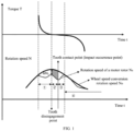
- FIG. 1 taking a process of changing the output torque of the motor from the positive torque to the negative torque as an example, a speed difference between a driving gear rotation speed and a driven gear rotation speed in a process of a driving gear crossing backlashes is integrated along time, that is, a shaded area in the figure, which is a backlash value.
- a relative movement of the driving gear and the driven gear can be divided into four stages, which are 1, 2, 3 and 4 in FIG. 1 respectively.
- Stage 1 is a stage of positive torque reduction and elastic pressure release; stage 2 is a tooth approaching process of the driving gear; stage (3) is a process of contact and compression between the driving gear and the driven gear; stage (4) is a stage of a negative torque increase and elastic pressure compression of the motor.
- ⁇ N 1 in FIG. 1 could be used to indicate a speed difference value of a wheel end conversion rotation speed and a driving gear rotation speed at a disengagement moment of the driving gear and the driven gear.
- the present application provides a motor control method of an electric vehicle, by analyzing a dynamic process when a meshing direction of a driving gear of a motor in a transmission system changes, combining characteristics of high precision driving gear position and rotation speed measurement of the motor, and a torque adjusted rapidly by the motor, when detecting that a direction of an output torque of the motor changes, by controlling the driving gear to perform a tooth approaching operation, a speed difference when the driving gear disengages from a driven gear and then re-contacts with the same is reduced, thereby reducing or even eliminating vibration and noise between the driving gear and the driven gear caused by inertia impact.
- FIG. 2 is a schematic structural diagram of an electric vehicle provided by an embodiment of the present application.
- the electric vehicle could include an Electronic Control Unit (Electronic Control Unit, ECU), a left front wheel, a left front wheel speed sensor, a left front transmission axle, a front motor rotating transformer, a front motor, a front motor controller and driver, a front motor deceleration differential, a right front transmission axle, a right front wheel speed sensor, a right front wheel, a high voltage battery, a left rear wheel, a left rear wheel speed sensor, a rear motor rotating transformer, a rear motor, a rear motor controller and driver, a rear motor deceleration differential, a left rear transmission axle, a right rear transmission axle, a right rear wheel speed sensor and a right rear wheel.
- ECU Electronic Control Unit
- a output torque of the front motor is transmitted to the left front wheel and the right front wheel by the front motor deceleration differential;
- a output torque of the rear motor is transmitted to the left rear wheel and the right rear wheel by the rear motor deceleration differential, and then wheel speeds corresponding to wheels are collected by the left front wheel speed sensor, the right front wheel speed sensor, the left rear wheel speed sensor and the right rear wheel speed sensor respectively.
- the speed values detected by the left front wheel speed sensor, the right front wheel speed sensor, the left rear wheel speed sensor and the right rear wheel speed sensor are all collected and processed by the ECU, and the ECU determines whether torque directions of the output torques of the front motor and the rear motor change by the obtained wheel speeds, and when the torque directions change, the ECU controls the driving gear to perform a tooth approaching operation, thus realizing an active control of rotation speed of the driving gear, which can reduce or even avoid the problems of large initial speed and a long time consumption when the driving gear pass through a tooth gap. Therefore, the problems that power output delay, vibration and noise can be reduced or even avoided.
- FIG. 3 is flowchart of a motor control method of an electric vehicle provided by an embodiment of the present application, as shown in FIG.3 , the method includes the following steps.
- S301 detecting a relative deformation of a transmission system between a driving gear and a wheel end of a motor.
- a direction of an output torque of the motor when a direction of an output torque of the motor is about to change, it is determined whether a meshing direction of a driving gear of the motor and a driven gear of the transmission system is about to change, that is, when the direction of the output torque of the motor changes, it means that the driving gear will disengage from the driven gear, that is, an elastic force between the driving gear and the driven gear will be released, so that the elastic force is reduced and the relative deformation of the transmission system between the driving gear and the wheel end is also reduced.
- the meshing direction of the driving gear and the driven gear of the motor can be continuously detected, and the relative deformation of the transmission system between the driving gear and the wheel end can be continuously calculated, so that the relative deformation of the transmission system between the driving gear and the wheel end can be determined when the direction of the output torque of the motor is detected to be about to change.
- the relative deformation of the transmission system between the driving gear and the wheel end could include a gear deformation and an axle deformation.
- S302 determining a first speed difference value of a first driving gear rotation speed and a first wheel end conversion rotation speed when the relative deformation is a first threshold.
- the relative deformation being the first threshold value is used to indicate that the driving gear starts to disengage from a driven gear of the transmission system
- the first driving gear rotation speed is a rotation speed of the driving gear at a disengagement moment of the driving gear and the driven gear
- the first wheel end conversion rotation speed is a rotation speed obtained by performing a speed ratio conversion on the wheel end rotation speed of the electric vehicle at the disengagement moment.
- the movement process could be a movement decomposing process between the driving gear and the driven gear after a fixed coordinate system is transformed into a rotating coordinate system by a coordinate (park) transformation, where a frequency of the rotating coordinate system is obtained by performing a wheel speed conversion (the wheel speed is relatively stable, and a relatively stable coordinate system frequency can be obtained).
- a coordinate (park) transformation where a frequency of the rotating coordinate system is obtained by performing a wheel speed conversion (the wheel speed is relatively stable, and a relatively stable coordinate system frequency can be obtained).
- the relative movement between the driving gear and the driven gear can be equivalent to the following six stages or moments: an elastic release stage, a moment when the driving gear starts to disengage from the driven gear, a free rotation stage of the driving gear, a moment when the driving gear starts to re-mesh with the driven gear, a moment when the driving gear start to contact with the driven gear, and an elastic compression stage.
- the driving gear and the driven gear starting to disengage also could be determined by the following ways: in a process of elastic deformation recovery between the driving gear and the driven gear, a relative deformation recovery is equal to the elastic deformation.
- a speed difference value of the first driving gear rotation speed and the first wheel end conversion rotation speed at this moment can be determined, and the speed difference value is recorded as the first speed difference value, so as to determine a required output torque of the motor according to the first speed difference value.
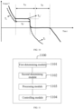
- FIG. 5 is a schematic curve diagram for controlling a driving gear to perform tooth approaching provided by an embodiment of the present application.
- the relative movement of the driving gear and the driven gear can be decomposed into three stages, where stage 1 can be a positive torque reduction and elastic release stage, stage 2 can be tooth approaching stage of the driving gear, and stage 3 can be a stage that a negative torque increase and elastic compress.
- stage 1 can be a positive torque reduction and elastic release stage
- stage 2 can be tooth approaching stage of the driving gear
- stage 3 can be a stage that a negative torque increase and elastic compress.
- a speed difference between the driving gear and the driven gear in a process of the driving gear passing through a backlash can be integrated along time, that is, a shaded area in FIG. 5 , which is a backlash value.
- the output torque of the motor is obtained by calculating, i.e., T 12 and T 23 .
- an integral range of an elastic release deformation can be as follows: from a moment when the user releases the throttle and thus the driven gear disengages, until a moment when the output torque of the motor is zero or an integral value of the elastic release deformation is equal to a preset elastic deformation value.
- the preset elastic deformation value can be represented by a mapping table of the output torque and the elastic release deformation. When a cumulative integral value of the elastic release deformation reaches the preset elastic deformation value, the elastic release deformation is considered to be end.
- a preset method of the mapping table can be as follows: giving different locked-rotor torques of the motor on the whole vehicle or a transmission system assembly in a static state, and measuring a rotation angle of a motor axle under this locked-rotor torque.
- an integral range of backlash can be from the end of the elastic release deformation to a moment when a backlash integral value reaches a preset backlash value S or a self-learning backlash value S.
- an integral range of the elastic compression deformation can be from the end of backlash integral to a moment when the driving gear re-meshes with the driven gear.
- L can be used to indicate an integral of a relative position difference between the driving gear and the driven gear, and both the elastic deformation integral and the backlash integral can be expressed by this value, the unit is rad rad
- ⁇ N can be used to indicate a speed difference between the driving gear and the driven gear, and the unit is revolution per minute rpm
- ⁇ can be used to indicate a speed difference between the driving gear and the driven gear after unit conversion, and the unit is rad/s.
- S304 controlling the driving gear to perform a tooth approaching operation relative to the driven gear according the output torque.
- the driving gear is controlled to perform a tooth approaching operation relative to the driven gear by controlling the output torque of the motor, so as to reduce the speed difference between the driving gear and the driven gear when teeth contact and reduce inertia impact when teeth contact, thereby eliminating vibration and noise.
- the elastic deformation is calculated, and a relative initial speed caused by the elastic deformation is identified, so as to implement a corresponding control strategy of the motor output torque according to the initial speed to control the driving gear to actively perform a tooth approaching operation, thus effectively reducing or even avoiding or solving the inertia impact when the teeth contact, thereby eliminating vibration and noise.
- the contact and compression stages in a torque smoothing processing solution can be eliminated, the time for the driving gear to pass through the backlash can be shortened, and a change process of a tooth meshing surface can be shortened, that is, the change time of a positive torque and a negative torque can be reduced, torque response can be improved, and there is better driving performance.
- the determining the output torque of the motor according to the first speed difference value includes: determining a product of the first speed difference value and a first time length as a first product, where the first time length is a duration from the disengagement moment to a contact moment of the driving gear and the driven gear; and if the first product is less than a preset backlash value, determining that the output torque includes a first torque and a second torque, wherein directions of the first torque and the second torque are opposite, the first torque is a required torque in a time interval from the disengagement moment to a transition moment of the motor in an acceleration state and a deceleration state, and the second torque is a required torque in a time interval from the transition moment to the contact moment.
- the product of the first speed difference value and the first time length can be determined first, i.e., ⁇ N 1 ⁇ (t 12 + t 23 ), when ⁇ N 1 ⁇ (t 12 + t 23 ) ⁇ 2S (where S can be used to indicate a default backlash value, and it is an optimal solution when the preset backlash value is 2S), directions of the first torque T 12 and the second torque T 23 calculated by the first speed difference value are opposite, and at this moment, an output torque curve can be shown in FIG. 5 .
- the rotation speed of the driving gear can be actively controlled, that is, a torque control of first decelerating and then accelerating (or first accelerating and then decelerating, which depending on a change direction of the output torque of the motor), which reduces a time taken for the driving gear to cross the backlash and reduces or even avoids a problem of slow dynamic response; by controlling the rotation speed of the driving gear, the rotation speed difference when the driving gear and the driven gear re-contact can be reduced. Under an ideal condition, the rotation speed difference can be reduced to zero, and vibration and noise can be completely eliminated.
- the first torque and the second torque are determined by the following ways: determining a second speed difference value of a current driving gear speed and a second wheel end conversion rotation speed according to the preset backlash value, the first speed difference value and the first time length at the transition moment, where the second wheel end conversion rotation speed is a rotation speed obtained by performing a speed ratio conversion on the wheel end rotation speed of the electric vehicle at the transition moment; determining a second driving gear rotation speed according to the second speed difference value and the second wheel end conversion rotation speed, where the second driving gear rotation speed is a rotation speed of the driving gear at the transition moment; determining the first torque according to the second driving gear rotation speed, the first driving gear rotation speed, a duration of the disengagement moment and the transition moment, and a sliding friction force of the driving gear under the second driving gear rotation speed; and determining the second torque according to the second driving gear rotation speed, a third driving gear rotation speed, a duration of the transition moment and the contact moment, and a sliding friction force of the driving gear under the third driving gear rotation speed, where the
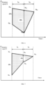
- a geometric model simplify processing can be performed on the shaded area in FIG. 5 , as shown in FIG. 6 , the output torque of the motor can be determined by a simplified model shown in FIG. 6 .
- N O1 , N R1 , t 12 and t 23 are determined, N O2 and N O3 are determined values, a time component of N R2 is a determined value, and an enclosed area backlash value S of N O1 , N O3 , N R1 and N R2 is also a determined value.
- speed components of ⁇ N 2 and N R2 can be obtained. Then a speed change rate a 12 can be obtained by derivation for line segment N R1 N R2 , a speed change rate a 23 can be obtained by derivation for line segment N R2 N O3 , the first torque T 12 and the second torque T 23 can be determined according to the speed change rates a 12 and a 23 .
- the driving gear in addition to determining the output torque of the motor to control the driving gear to complete a tooth approaching operation by determining t 12 and t 23 , the driving gear can also complete the tooth approaching operation by given values of T 12 and T 23 .
- time t 12 corresponding to the first torque T 12 and time t 23 corresponding to the second torque T 23 can be determined, that is, the whole tooth approaching process can be determined.
- N O1 and N R1 are determined, and the whole tooth approaching process can also be determined by determining any two quantities of t 12 , t 23 , T 12 , T 23 and t 13 .
- the rotation speed of the driving gear that is, the torque control of first decelerating and then accelerating (or first accelerating and then decelerating, which depending on the direction in which the output torque of the motor is about to change), which reduces a time taken for the driving gear to cross the backlash and reduces or even avoids a problem of slow dynamic response;
- the rotation speed difference when the driving gear and the driven gear re-contact can be reduced.
- the rotation speed difference can be reduced to zero, and vibration and noise can be completely eliminated.
- the determining the output torque of the motor according to the first speed difference value further includes: if the first product is greater than or equal to the preset backlash value, determining a product of the first speed difference value and a second time length as a second product, where the second time length is a duration from the disengagement moment to the transition moment; and if the second product is less than the preset backlash value, determining that the output torque includes the first torque and the second torque, where the directions of the first torque and the second torque are the same.
- a geometric model simplify processing can be performed on the shaded area in FIG. 5 to obtain a simplified model as shown in FIG. 7 , at this time, formulas for determining the first torque T 12 and the second torque T 23 are the same with when ⁇ N 1 ⁇ (t 12 + t 23 ) ⁇ 2S in the above, but when ⁇ N 1 ⁇ t 12 ⁇ 2S, the directions of the first torque T 12 and the second torque T 23 are the same, and a output torque curve can be shown in FIG. 8 .
- a dotted line T 1 can be used to represent a possible torque curve in a descending stage of the output torque, and the torque curve depends on a torque descending slope u, a disengagement moment t 1 of the driving gear and the driven gear, and an initial speed difference ⁇ N 1 when the driving gear is disengaged from the driven gear, where u can be used to represent an average slope of the torque descending from the moment when the user releases the throttle to the disengagement moment of the driving gear and the driven gear (t 0 to t 1 ), that is, the torque descending slope.
- the rotation speed of the driving gear that is, the torque control of first decelerating and then accelerating (or first accelerating and then decelerating, which depending on the direction in which the output torque of the motor will change), which reduces a time taken for the driving gear to cross the backlash and reduces or even avoids a problem of slow dynamic response;
- the rotation speed difference when the driving gear and the driven gear re-contact can be reduced.
- the rotation speed difference can be reduced to zero, and vibration and noise can be completely eliminated.
- the determining the output torque of the motor according to the first speed difference value further includes: if the second product is greater than or equal to the preset backlash value, determining a third wheel end conversion rotation speed at a target moment, where the third wheel end conversion rotation speed is a rotation speed obtained by performing a speed ratio conversion on the wheel end rotation speed of the electric vehicle at the target moment, the target moment is a moment when the driving gear re-contact with the driven gear in the second time; and determining a third torque according to the third wheel end conversion rotation speed, the first driving gear rotation speed and a duration of the disengagement moment and the target moment, where the third torque is a required torque in a time interval from the disengagement moment to the target moment, and the output torque includes the third torque.
- a geometric model simplify processing can be performed on the shaded area in FIG. 5 to obtain a simplified model as shown in FIG. 9 , at this time, it is only necessary to calculate a required torque within a time length from t 1 to t 2 , , t 2 , is a target moment and also is a moment when the driving gear re-contact with the driven gear within a time length from t 1 to t 2 .
- an output torque curve can be as shown in FIG. 10 .
- a dotted line T 1 can be used to represent a possible torque curve in a descending stage of the output torque, and the torque curve depends on a torque descending slope u, a disengagement moment t 1 of the driving gear and the driven gear, and an initial speed difference ⁇ N 1 when the driving gear is disengaged from the driven gear, and a dotted line T 2 can be used to represent a selectable torque curve after the time length of t 12' .
- the rotation speed of the driving gear that is, the torque control of first decelerating and then accelerating (or first accelerating and then decelerating, which depending on the direction in which the output torque of the motor will change), which reduces a time taken for the driving gear to cross the backlash and reduces or even avoids a problem of slow dynamic response;
- the rotation speed difference when the driving gear and the driven gear re-contact can be reduced.
- the rotation speed difference can be reduced to zero, and vibration and noise can be completely eliminated.
- the detecting the relative deformation of the transmission system between the driving gear and the wheel end of the motor includes: determining whether a direction of the output torque of the motor is about to change; when the direction of output torque is about to change, determining whether a meshing direction of the driving gear and the driven gear of the motor is about to change; when the meshing direction of the driving gear and the driven gear is about to change, determining the relative deformation.
- whether the direction of the output torque of the motor is about to change can be determined, and whether the direction of the output torque is about to change can include various situations such as the direction of the output torque changing from positive to negative, changing from negative to positive, being zero positive, being zero negative, etc.
- the direction of output torque is about to change
- whether the meshing direction of the driving gear and the driven gear of the motor is about to change can be determined, and when the meshing direction of the driving teeth and the driven teeth is about to change, the relative deformation of the transmission system between the driving gear and the wheel end of the motor is determined.
- the determining the relative deformation of the transmission system between the driving gear and the wheel end of the motor further includes: determining a third speed difference value of a current driving gear speed and a driven gear rotation speed when detecting that the output torque of the motor changes; determining a relative displacement of the driving gear and the driven gear according to the third speed difference value; and determining the relative deformation according to the relative displacement.
- the third speed difference value of the driving gear rotation speed and the driven gear rotation speed can be calculated in real time in a subsequent movement process of the driving gear and the driven gear, and a speed difference value in each time period of multiple time periods can be determined. Then, the relative displacement of the driving gear and the driven gear can be calculated by the speed difference value in each time period and the time length of the corresponding time period, so as to obtain the relative deformation of the driving gear and the driven gear.
- relative initial speeds of the driving gear caused by different relative deformations are different. Therefore, different output torque control strategies can be implemented for different initial speeds, so as to realize a rapid change of positive and negative torques and optimize the dynamic response of the electric vehicle.
- the motor control method of the electric vehicle provided by the present application, by actively controlling the output torque of the motor when the meshing direction of the driving gear and the driven gear changes, the time length taken for the driving gear to re-contact with the driven gear is reduced, positive and negative torque changes are accelerated, power output delay is shortened, and driving performance is optimized.
- By actively controlling the output torque of the motor when the meshing direction of the driving gear and the driven gear changes a speed difference when the driving gear contacts with the driven gear is eliminated, and the noise and impact caused by inertial impact are eliminated.
- the technical solution provided by the present application is a technical method that can not only optimize the driving performance of the electric vehicle, but also eliminate noise and impact caused by inertial impact.
- FIG. 11 is a schematic structural diagram of a motor control apparatus of an electric vehicle provided by an embodiment of the present application.
- a motor control apparatus 1100 of the electric vehicle includes:
- the processing module 1103 when determining the output torque of the motor according to the first speed difference value, is specifically configured to: determine a product of the first speed difference value and a first time length as a first product, where the first time length is a duration from the disengagement moment to a contact moment of the driving gear and the driven gear; and if the first product is less than a preset backlash value, determine that the output torque includes a first torque and a second torque, where directions of the first torque and the second torque are opposite, the first torque is a required torque in a time interval from the disengagement moment to a transition moment of the motor in an acceleration state and a deceleration state, and the second torque is a required torque in a time interval from the transition moment to the contact moment.
- the motor control apparatus 1100 of the electric vehicle may further include a third determining module (not shown), the third determining module may be specifically configured to determine the first torque and the second torque by the following ways: determine a second speed difference value of a current driving gear speed and a second wheel end conversion rotation speed according to the preset backlash value, the first speed difference value and the first time length at the transition moment, where the second wheel end conversion rotation speed is a rotation speed obtained by performing a speed ratio conversion on the wheel end rotation speed of the electric vehicle at the transition moment; determine a second driving gear rotation speed according to the second speed difference value and the second wheel end conversion rotation speed, where the second driving gear rotation speed is a rotation speed of the driving gear at the transition moment; determine the first torque according to the second driving gear rotation speed, the first driving gear rotation speed, a duration of the disengagement moment and the transition moment, and a sliding friction force of the driving gear under the second driving gear rotation speed; and determine the second torque according to the second driving gear rotation speed, a third driving gear rotation speed, a duration of the first torque
- the processing module 1103 is further specifically configured to: if the first product is greater than or equal to the preset backlash value, determine a product of the first speed difference value and a second time length as a second product, where the second time length is a duration from the disengagement moment to the transition moment; and if the second product is less than the preset backlash value, determine that the output torque includes the first torque and the second torque, where the directions of the first torque and the second torque are the same.
- the processing module 1103 is further specifically configured to: if the second product is greater than or equal to the preset backlash value, determine a third wheel end conversion rotation speed at a target moment, where the third wheel end conversion rotation speed is a rotation speed obtained by performing a speed ratio conversion on the wheel end rotation speed of the electric vehicle at the target moment, the target moment is a moment when the driving gear re-contact with the driven gear in the second time; and determine a third torque according to the third wheel end conversion rotation speed, the first driving gear rotation speed and a duration of the disengagement moment and the target moment, where the third torque is a required torque in a time interval from the disengagement moment to the target moment, and the output torque includes the third torque.
- the first determining module 1101 when determining the relative deformation of the transmission system between the driving gear and the wheel end of the motor, can further be specifically configured to: determine a third speed difference value of a current driving gear speed and a driven gear rotation speed when detecting that the output torque of the motor changes; determine a relative displacement of the driving gear and the driven gear according to the third speed difference value; and determine the relative deformation according to the relative displacement.
- the motor control apparatus of the electric vehicle provided by the embodiment of the present application is used to implement the technical solution of the motor control method of the electric vehicle in the aforementioned method embodiments, and its implementation principle and technical effect are similar, so the details are not repeated here.
- FIG. 12 is a block diagram of an electric vehicle illustrated according to an exemplary embodiment. As shown in FIG. 12 , the electric vehicle 1200 includes:
- the memory 1212 may be independent or integrated with the processor 1211.
- the electronic device 1200 may further include: a bus, configured to connect the above devices.
- the memory can be, but not limited to, a Random Access Memory (Random Access Memory, RAM), a Read Only Memory (Read Only Memory, ROM), a Programmable Read-Only Memory (Programmable Read-Only Memory, PROM), an Erasable Programmable Read-Only Memory (Erasable Programmable Read-Only Memory, EPROM), an Electric Erasable Programmable Read-Only Memory (Electric Erasable Programmable Read-Only Memory, EEPROM), etc.
- the memory is configured to store programs, and the processor executes the programs after receiving the execution instructions.
- the software programs and modules in the above memory may also include an operating system, which may include various software components and/or drivers for managing system tasks (such as memory management, storage device control, power management, etc.), and may communicate with various hardware or software components, thereby providing an operating environment for other software components.
- an operating system which may include various software components and/or drivers for managing system tasks (such as memory management, storage device control, power management, etc.), and may communicate with various hardware or software components, thereby providing an operating environment for other software components.
- the processor can be an integrated circuit chip with signal processing capability.
- the processor can be a general-purpose processor, including a Central Processing Unit (Central Processing Unit, CPU) and a Network Processor (Network Processor, NP).
- CPU Central Processing Unit
- NP Network Processor
- the methods, steps and logic blocks disclosed in the embodiments of the present application can be realized or executed.
- the general processor can be a microprocessor or the processor can be any conventional processor, etc.
- An embodiment of the present application further provides a computer-readable storage medium having computer executable instructions stored therein, where when the computer executable instructions are executed by a processor, the technical solution of the motor control method of the electric vehicle in the aforementioned method embodiments is implemented.
- An embodiment of the present application further provides a computer program product including a computer program, where when the computer program is executed by a processor, the technical solution of the motor control method of the electric vehicle in the aforementioned method embodiments is implemented.
- the aforementioned program can be stored in a computer-readable storage medium.
- the steps including the above method embodiments are executed; and the aforementioned storage media includes a ROM, a RAM, a magnetic disk or an optical disk and other media that can store program codes.
Landscapes
- Engineering & Computer Science (AREA)
- Mechanical Engineering (AREA)
- Transportation (AREA)
- Combustion & Propulsion (AREA)
- Chemical & Material Sciences (AREA)
- Automation & Control Theory (AREA)
- Power Engineering (AREA)
- General Engineering & Computer Science (AREA)
- Physics & Mathematics (AREA)
- Mathematical Physics (AREA)
- Electric Propulsion And Braking For Vehicles (AREA)
- Motor Power Transmission Devices (AREA)
- Control Of Ac Motors In General (AREA)
Abstract
Description
- The present application relates to the field of electric vehicle technology and, in particular, to an electric vehicle, a motor control method thereof, an apparatus and a storage medium.
- With the development of electric vehicle technology, the application scope of electric vehicles is more and more extensive. For users, driving comfort is one of the main reasons for choosing electric vehicles. In a driving process of an electric vehicle, when a output torque of a motor changes between a positive torque and a negative torque, changing of a gear meshing direction of the motor will lead to gear rattling, thus generating vibration and noise that users can obviously perceive and affecting driving comfort. In addition, gear rattling may also cause damage to transmission mechanisms such as gears or splines.
- At present, in order to solve the above problems, an output torque of the motor is usually processed by a filtering processing method (for example, a torque smoothing processing method) to reduce vibration and noise when the output torque of the motor is changed between the positive torque and the negative torque. However, there is still great vibration and noise in this way, which leads to a poor driving experience for a user.
- The present application provides an electric vehicle, a motor control method thereof, an apparatus and a storage medium, which are used to solve problems that the motor and a transmission system thereof have great vibration and noise during driving of the electric vehicle.
- In a first aspect, an embodiment of the present application provides a motor control method of an electric vehicle, including: detecting a relative deformation of a transmission system between a driving gear and a wheel end of a motor; determining a first speed difference value of a first driving gear rotation speed and a first wheel end conversion rotation speed when the relative deformation is a first threshold, where the relative deformation being the first threshold value is used to indicate that the driving gear starts to disengage from a driven gear of the transmission system, the first driving gear rotation speed is a rotation speed of the driving gear at a disengagement moment of the driving gear and the driven gear, and the first wheel end conversion rotation speed is a rotation speed obtained by performing a speed ratio conversion on the wheel end rotation speed of the electric vehicle at the disengagement moment; determining an output torque of the motor according to the first speed difference value; and controlling the driving gear to perform a tooth approaching operation relative to the driven gear according the output torque.
- In one possible embodiment, the determining the output torque of the motor according to the first speed difference value includes: determining a product of the first speed difference value and a first time length as a first product, where the first time length is a duration from the disengagement moment to a contact moment of the driving gear and the driven gear; and if the first product is less than a preset backlash value, determining that the output torque includes a first torque and a second torque, where directions of the first torque and the second torque are opposite, the first torque is a required torque in a time interval from the disengagement moment to a transition moment of the motor in an acceleration state and a deceleration state, and the second torque is a required torque in a time interval from the transition moment to the contact moment.
- In one possible embodiment, the first torque and the second torque are determined by the following ways: determining a second speed difference value of a current driving gear speed and a second wheel end conversion rotation speed according to the preset backlash value, the first speed difference value and the first time length at the transition moment, where the second wheel end conversion rotation speed is a rotation speed obtained by performing a speed ratio conversion on the wheel end rotation speed of the electric vehicle at the transition moment; determining a second driving gear rotation speed according to the second speed difference value and the second wheel end conversion rotation speed, where the second driving gear rotation speed is a rotation speed of the driving gear at the transition moment; determining the first torque according to the second driving gear rotation speed, the first driving gear rotation speed, a duration of the disengagement moment and the transition moment, and a sliding friction force of the driving gear under the second driving gear rotation speed; and determining the second torque according to the second driving gear rotation speed, a third driving gear rotation speed, a duration of the transition moment and the contact moment, and a sliding friction force of the driving gear under the third driving gear rotation speed, where the third driving gear rotation speed is a rotation speed of the driving gear at the contact moment.
- In one possible embodiment, the determining the output torque of the motor according to the first speed difference value further includes: if the first product is greater than or equal to the preset backlash value, determining a product of the first speed difference value and a second time length as a second product, where the second time length is a duration from the disengagement moment to the transition moment; and if the second product is less than the preset backlash value, determining that the output torque includes the first torque and the second torque, where the directions of the first torque and the second torque are the same.
- In one possible embodiment, the determining the output torque of the motor according to the first speed difference value further includes: if the second product is greater than or equal to the preset backlash value, determining a third wheel end conversion rotation speed at a target moment, where the third wheel end conversion rotation speed is a rotation speed obtained by performing a speed ratio conversion on the wheel end rotation speed of the electric vehicle at the target moment, the target moment is a moment when the driving gear re-contact with the driven gear in the second time; and determining a third torque according to the third wheel end conversion rotation speed, the first driving gear rotation speed and a duration of the disengagement moment and the target moment, where the third torque is a required torque in a time interval from the disengagement moment to the target moment, and the output torque includes the third torque.
- In one possible embodiment, the determining the relative deformation of the transmission system between the driving gear and the wheel end of the motor further includes: determining a third speed difference value of a current driving gear speed and a driven gear rotation speed when detecting that the output torque of the motor changes; determining a relative displacement of the driving gear and the driven gear according to the third speed difference value; and determining the relative deformation according to the relative displacement.
- In a second aspect, an embodiment of the present application provides a motor control apparatus of an electric vehicle, including: a detecting module, configured to detect a relative deformation of a transmission system between a driving gear and a wheel end of a motor; a determining module, configured to determine a first speed difference value of a first driving gear rotation speed and a first wheel end conversion rotation speed when the relative deformation is a first threshold, where the relative deformation being the first threshold value is used to indicate that the driving gear starts to disengage from a driven gear of the transmission system, the first driving gear rotation speed is a rotation speed of the driving gear at a disengagement moment of the driving gear and the driven gear, and the first wheel end conversion rotation speed is a rotation speed obtained by performing a speed ratio conversion on the wheel end rotation speed of the electric vehicle at the disengagement moment; a processing module, configured to determine an output torque of the motor according to the first speed difference value; and a controlling module, configured to control the driving gear to perform a tooth approaching operation relative to the driven gear according the output torque.
- In a third aspect, an embodiment of the present application provides an electric vehicle, including: a processor and a memory in communication connection with the processor; where the memory stores computer executable instructions; and the processor executes the computer executable instructions stored in the memory to implement the motor control method of the electric vehicle in the first aspect.
- In a fourth aspect, an embodiment of the present application provides a computer-readable storage medium having computer executable instructions stored therein, where when the computer executable instructions are executed by a processor, the motor control method of the electric vehicle in the first aspect is implemented.
- In a fifth aspect, an embodiment of the present application provides a computer program product, including a computer program, where when the computer program is executed by a processor, the motor control method of the electric vehicle in the first aspect is implemented.
- In the electric vehicle, the motor control method thereof, an apparatus and a storage medium provided by the present application, by analyzing a dynamic process when a meshing direction of a driving gear of a motor changes, combining characteristics of high precision driving gear position and rotation speed measurement of the motor, and a torque adjusted rapidly by the motor, when detecting that a direction of an output torque of the motor is about to change, by controlling the torque of the driving gear to perform an active tooth approaching operation, a speed difference when the driving gear disengages from a driven gear and then re-contacts with the same is reduced, thereby reducing or even eliminating vibration and noise between the driving gear and the driven gear caused by inertia impact. In the present application, there is no need to change original hardware of the electric vehicle or add a new sensor, only by calculating a wheel end rotation speed, a driving gear speed of the motor and a backlash, a tooth approaching control can be realized. At the same time, in the present application, restriction on descending slope or ascending slope of the output torque of the motor can be released to the greatest extent when the direction of the output torque is about to change, so that the output torque of the motor can follow operations and expectations of users, which can avoid problems of an acceleration feeling after the user releases the throttle or a poor response of an electric vehicle after the user steps on the throttle caused on restriction on the descending slope or ascending slope of the output torque of the motor in the related art.
- In order to illustrate technical solutions in embodiments of the present application or in the related art more clearly, the drawings needed to be used in the description of embodiments or the prior art will be briefly introduced below. Obviously, the drawings in the following description are some embodiments of the present application, and other drawings can be obtained for those of ordinary skills in the art according to these drawings without paying creative effort.
-
FIG. 1 is a schematic curve diagram of a torque filtering method provided by the related art. -
FIG. 2 is a schematic structural diagram of an electric vehicle provided by an embodiment of the present application. -
FIG. 3 is flowchart of a motor control method of an electric vehicle provided by an embodiment of the present application. -
FIG. 4 is a schematic movement process diagram of a driving gear and a driven gear provided by an embodiment of the present application. -
FIG. 5 is a schematic curve diagram for controlling a driving gear to perform tooth approaching provided by an embodiment of the present application. -
FIG. 6 is a schematic diagram of a first embodiment for simplifying a geometric model for a shadow area inFIG. 5 provided by an embodiment of the present application. -
FIG. 7 is a schematic diagram of a second embodiment for simplifying a geometric model for a shadow area inFIG. 5 provided by an embodiment of the present application. -
FIG. 8 is a schematic curve diagram of an output torque of a motor corresponding toFIG. 7 provided by an embodiment of the present application. -
FIG. 9 is a schematic diagram of a third embodiment for simplifying a geometric model for a shadow area inFIG. 5 provided by an embodiment of the present application. -
FIG. 10 is a schematic curve diagram of an output torque of a motor corresponding toFIG. 9 provided by an embodiment of the present application. -
FIG. 11 is a schematic structural diagram of a motor control apparatus of an electric vehicle provided by an embodiment of the present application. -
FIG. 12 is a block diagram of an electric vehicle illustrated according to an exemplary embodiment. - In order to make purposes, in order to make technical solutions and advantages of embodiments of the present application more clear, the technical solutions of embodiments of the present application will be described clearly and completely with the drawings of the present application in the following, obviously, described embodiments are some embodiments of the present application, but not all embodiments. Based on the embodiments of the present application, all other embodiments made by those skilled in the art under an inspiration of the embodiment belong to the protection scope of the present application.
- The terms "first", "second", "third" and "third" and so on (if any) in the description and claims of the present application and the above drawings are used to distinguish similar objects, and not necessarily used to describe a specific order or sequence. It should be understood that data used in this way could be exchanged under an appropriate condition, so that the embodiments of the present application described herein can be implemented in other orders than those illustrated or described herein. In addition, the terms "including" and "having" any variations thereof are intended to cover non-exclusive inclusion, for example, a process, a method, a system, a product or a device that includes a series of steps or units is not necessarily limited to those steps or units explicitly listed, but could include other steps or units not explicitly listed or inherent to such processes, methods, products or devices.
- First of all, the terms involved in the present application will be explained.
- Torque: a special moment of force that makes an object rotate. A motor torque is an output torque of the motor.
- Backlash: a gap between tooth surfaces when a pair of gears mesh. The backlash is a necessary parameter for gear meshing smooth operating.
- Relative deformation: a deformation of non-rigid materials when they are stressed, including but not limited to torsion and offset and so on.
- In the related art provided in the background, there are at least the following technical problems.
- With the increasingly rigorous control for carbon emission in countries all over the world and date table of carbon peaking and carbon neutrality being proposed, and a timetable for banning the sale of gasoline vehicles is designedly proposed. Meanwhile, new energy vehicles, that is, electric vehicles, is vigorously encouraged and supported. From perspective of the current expanding trend of new energy application scope, the scale of research and development, production and application of electric vehicles will increase at a high speed. A driving process of the electric vehicle is implemented by controlling an output torque of a motor according to a target torque determined by a vehicle controller or a motor controller. When the motor changes between a positive torque and a negative torque, that is, when a direction of the output torque of the motor changes, a gear meshing direction of the motor changes, which will lead to gear rattling, thus generating vibration and noise that users can obviously perceive and affecting driving comfort. In addition, gear rattling may also cause damage to transmission mechanisms such as gears or splines.
- For the above problems, in the related art, an output torque of the motor is usually processed by a filtering processing method to reduce vibration and noise when the output torque of the motor is changed between the positive torque and the negative torque, and the filtering processing method could be a torque smoothing processing method. As shown in
FIG. 1 , taking a process of changing the output torque of the motor from the positive torque to the negative torque as an example, a speed difference between a driving gear rotation speed and a driven gear rotation speed in a process of a driving gear crossing backlashes is integrated along time, that is, a shaded area in the figure, which is a backlash value. InFIG. 1 , a relative movement of the driving gear and the driven gear can be divided into four stages, which are ①, ②, ③ and ④ inFIG. 1 respectively.Stage ① is a stage of positive torque reduction and elastic pressure release;stage ② is a tooth approaching process of the driving gear; stage (3) is a process of contact and compression between the driving gear and the driven gear; stage (4) is a stage of a negative torque increase and elastic pressure compression of the motor. Δ N1 inFIG. 1 could be used to indicate a speed difference value of a wheel end conversion rotation speed and a driving gear rotation speed at a disengagement moment of the driving gear and the driven gear. - The following problems exist in the above related art: 1) by performing smoothing processing on the output torque, the driving gear slowly pass through a tooth gap in a way of small torque or zero torque output, which leads to a long time for the driving gear slowly pass through the tooth gap and a long time for changing between the positive and negative torques, so that the user feels that the output torque response of the motor is discontinuous and interrupted in terms of driving feeling, so as to perceive that the power output is delayed and the driving experience is poor; 2) when the driving gears contact with the driven gears at a maximum rotation speed difference value, inertial impact and collision noise will still be generated, and the improvement of vibration and noise is not obvious; 3) A torque slope of the driving gear and the driven gear in an elastic pressure release stage is too large, so the Δ N1 is too large, which leads to an initial speed of the driving gear passing through the backlash being too large, so as to lead to a speed difference between the driving gear and the driven gear being too large when they re-contact, and thus leads to serious impact and continuous jitter of the electric vehicle. Therefore, a descent or ascent of the torque slope in the elastic pressure release stage is limited, which leads to the fact that the electric vehicle still has acceleration after the user releases the throttle or the electric vehicle does not accelerate when the user steps on the throttle, and thus leads to a poor dynamic response of the electric vehicle.
- The present application provides a motor control method of an electric vehicle, by analyzing a dynamic process when a meshing direction of a driving gear of a motor in a transmission system changes, combining characteristics of high precision driving gear position and rotation speed measurement of the motor, and a torque adjusted rapidly by the motor, when detecting that a direction of an output torque of the motor changes, by controlling the driving gear to perform a tooth approaching operation, a speed difference when the driving gear disengages from a driven gear and then re-contacts with the same is reduced, thereby reducing or even eliminating vibration and noise between the driving gear and the driven gear caused by inertia impact.
- In one embodiment, the motor control method of the electric vehicle can be applied in an application scenario.
FIG. 2 is a schematic structural diagram of an electric vehicle provided by an embodiment of the present application. As shown inFIG. 2 , the electric vehicle could include an Electronic Control Unit (Electronic Control Unit, ECU), a left front wheel, a left front wheel speed sensor, a left front transmission axle, a front motor rotating transformer, a front motor, a front motor controller and driver, a front motor deceleration differential, a right front transmission axle, a right front wheel speed sensor, a right front wheel, a high voltage battery, a left rear wheel, a left rear wheel speed sensor, a rear motor rotating transformer, a rear motor, a rear motor controller and driver, a rear motor deceleration differential, a left rear transmission axle, a right rear transmission axle, a right rear wheel speed sensor and a right rear wheel. - In the above scenario, a output torque of the front motor is transmitted to the left front wheel and the right front wheel by the front motor deceleration differential; a output torque of the rear motor is transmitted to the left rear wheel and the right rear wheel by the rear motor deceleration differential, and then wheel speeds corresponding to wheels are collected by the left front wheel speed sensor, the right front wheel speed sensor, the left rear wheel speed sensor and the right rear wheel speed sensor respectively. The speed values detected by the left front wheel speed sensor, the right front wheel speed sensor, the left rear wheel speed sensor and the right rear wheel speed sensor are all collected and processed by the ECU, and the ECU determines whether torque directions of the output torques of the front motor and the rear motor change by the obtained wheel speeds, and when the torque directions change, the ECU controls the driving gear to perform a tooth approaching operation, thus realizing an active control of rotation speed of the driving gear, which can reduce or even avoid the problems of large initial speed and a long time consumption when the driving gear pass through a tooth gap. Therefore, the problems that power output delay, vibration and noise can be reduced or even avoided.
- Combining with the above scenario, the technical solution of the motor control method of the electric vehicle provided by the present application will be described in detail through several specific embodiments.
- The present application provides a motor control method of an electric vehicle.
FIG. 3 is flowchart of a motor control method of an electric vehicle provided by an embodiment of the present application, as shown inFIG.3 , the method includes the following steps. - S301: detecting a relative deformation of a transmission system between a driving gear and a wheel end of a motor.
- In this step, when a direction of an output torque of the motor is about to change, it is determined whether a meshing direction of a driving gear of the motor and a driven gear of the transmission system is about to change, that is, when the direction of the output torque of the motor changes, it means that the driving gear will disengage from the driven gear, that is, an elastic force between the driving gear and the driven gear will be released, so that the elastic force is reduced and the relative deformation of the transmission system between the driving gear and the wheel end is also reduced.
- Optionally, during a running process of the motor, the meshing direction of the driving gear and the driven gear of the motor can be continuously detected, and the relative deformation of the transmission system between the driving gear and the wheel end can be continuously calculated, so that the relative deformation of the transmission system between the driving gear and the wheel end can be determined when the direction of the output torque of the motor is detected to be about to change.
- Optionally, the relative deformation of the transmission system between the driving gear and the wheel end could include a gear deformation and an axle deformation.
- S302: determining a first speed difference value of a first driving gear rotation speed and a first wheel end conversion rotation speed when the relative deformation is a first threshold.
- In this step, the relative deformation being the first threshold value is used to indicate that the driving gear starts to disengage from a driven gear of the transmission system, the first driving gear rotation speed is a rotation speed of the driving gear at a disengagement moment of the driving gear and the driven gear, and the first wheel end conversion rotation speed is a rotation speed obtained by performing a speed ratio conversion on the wheel end rotation speed of the electric vehicle at the disengagement moment. When the relative deformation is the first threshold, it can be that the relative deformation is equal to zero, that is, the moment is the disengagement moment when the driving gear starts to disengage from the driven gear. A process of disengagement and re-contact between the driving gear and the driven gear can be shown in
FIG. 4, FIG. 4 is a schematic movement process diagram of a driving gear and a driven gear provided by an embodiment of the present application. InFIG.4 , the movement process could be a movement decomposing process between the driving gear and the driven gear after a fixed coordinate system is transformed into a rotating coordinate system by a coordinate (park) transformation, where a frequency of the rotating coordinate system is obtained by performing a wheel speed conversion (the wheel speed is relatively stable, and a relatively stable coordinate system frequency can be obtained). The relative movement between the driving gear and the driven gear can be equivalent to the following six stages or moments: an elastic release stage, a moment when the driving gear starts to disengage from the driven gear, a free rotation stage of the driving gear, a moment when the driving gear starts to re-mesh with the driven gear, a moment when the driving gear start to contact with the driven gear, and an elastic compression stage. - Optionally, the driving gear and the driven gear starting to disengage also could be determined by the following ways: in a process of elastic deformation recovery between the driving gear and the driven gear, a relative deformation recovery is equal to the elastic deformation.
- Optionally, when the relative deformation is the first threshold, that is, when the driving gear starts to disengage from the driven gear, a speed difference value of the first driving gear rotation speed and the first wheel end conversion rotation speed at this moment can be determined, and the speed difference value is recorded as the first speed difference value, so as to determine a required output torque of the motor according to the first speed difference value.
- S303: determining an output torque of the motor according to the first speed difference value.
- In this step, after the first speed difference value is determined, the output torque of the motor can be calculated by the first speed difference value, as shown in
FIG. 5, FIG. 5 is a schematic curve diagram for controlling a driving gear to perform tooth approaching provided by an embodiment of the present application. InFIG. 5 , taking that the output torque of the motor changes from a positive torque to a negative torque as an example, the relative movement of the driving gear and the driven gear can be decomposed into three stages, wherestage ① can be a positive torque reduction and elastic release stage,stage ② can be tooth approaching stage of the driving gear, and stage ③ can be a stage that a negative torque increase and elastic compress. InFIG.5 : - T12 can be used to indicate a first torque required to actively control the driving gear to perform tooth approaching, and its function is to make a motor rotor (the driving gear) accelerate and make a motor shaft quickly pass through a gear gap area;
- T12 can be used to indicate a second torque required to actively control the driving gear to perform tooth approaching, and its function is to reduce a rotation speed difference when meshing surfaces of gears contact, and then reduce inertia impact caused by the rotation speed difference;
- t0 can be used to indicate a moment when the output torque of the motor starts to decline when the user releases an accelerator;
- t1 can be used to indicate the moment when the driving gear starts to disengage from the driven gear;
- t2 can be used to indicate an end moment of action of the first torque T12 at which the rotation speed of the driving gear changes from acceleration to deceleration, and can be a preset time point;
- t3 can be used to indicate an end moment of action of the second torque T23, that is, a moment when the driving gear re-contact with the driven gear ;
- t01 can be used to indicate a duration from the time when the user releases the throttle to the time when the driving gear starts to disengage from the driven gear;
- t12 can be used to indicate an action time of the first torque T12;
- t23 can be used to indicate action time of the second torque T23;
- t13 can be used to indicate a total time of t12+t23, that is, an action time that actively controlling a driving gear to perform tooth approaching;
- No can be used to indicate a rotation speed obtained by performing a speed ratio conversion on the wheel end rotation speed, which is referred to as a wheel end conversion rotation speed for short;
- NO1 can be used to indicate the wheel end conversion rotation speed at the moment of t1;
- NO2 can be used to indicate the wheel end conversion rotation speed at the moment of t2;
- NO3 can be used to indicate the wheel end conversion rotation speed at the moment of t3;
- NR can be used to indicate a motor rotor rotation speed, that is, a driving gear rotation speed;
- NR1 can be used to indicate the driving gear rotation speed at the end of t01, that is, a driving gear rotation speed at the moment of t1;
- NR2 can be used to indicate the driving gear rotation speed at the end of t12, that is, the driving gear rotation speed at the moment of t2;
- ΔN1 can be used to indicate a speed difference between NO1 and NR1 at the moment of t1, that is, a rotation speed difference between the wheel end conversion rotation speed and the driving gear rotation speed at the disengagement moment of the driving gear and the driven gear;
- ΔN2 can be used to indicate a speed difference between NO2 and NR2 at the moment of t2, that is, a rotation speed difference between the wheel end conversion rotation speed and the driving gear rotation speed at an end moment of action of the first torque T12.
- Optionally, a speed difference between the driving gear and the driven gear in a process of the driving gear passing through a backlash can be integrated along time, that is, a shaded area in
FIG. 5 , which is a backlash value. By determining the first speed difference value, i.e., ΔN1, the output torque of the motor is obtained by calculating, i.e., T12 and T23. - Optionally, in
stage ① ofFIG. 5 , an integral range of an elastic release deformation can be as follows: from a moment when the user releases the throttle and thus the driven gear disengages, until a moment when the output torque of the motor is zero or an integral value of the elastic release deformation is equal to a preset elastic deformation value. The preset elastic deformation value can be represented by a mapping table of the output torque and the elastic release deformation. When a cumulative integral value of the elastic release deformation reaches the preset elastic deformation value, the elastic release deformation is considered to be end. A preset method of the mapping table can be as follows: giving different locked-rotor torques of the motor on the whole vehicle or a transmission system assembly in a static state, and measuring a rotation angle of a motor axle under this locked-rotor torque. - In
stage ② inFIG. 5 , an integral range of backlash can be from the end of the elastic release deformation to a moment when a backlash integral value reaches a preset backlash value S or a self-learning backlash value S. - In stage (3) in
FIG. 5 , an integral range of the elastic compression deformation can be from the end of backlash integral to a moment when the driving gear re-meshes with the driven gear. - Optionally, an integral calculation formula can be expressed as follows:
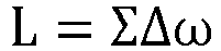


- S304: controlling the driving gear to perform a tooth approaching operation relative to the driven gear according the output torque.
- In this step, since an active control of a rotational speed of the driving gear is realized by controlling the output torque of the motor, the driving gear is controlled to perform a tooth approaching operation relative to the driven gear by controlling the output torque of the motor, so as to reduce the speed difference between the driving gear and the driven gear when teeth contact and reduce inertia impact when teeth contact, thereby eliminating vibration and noise.
- In the motor control method of an electric vehicle provided by the present application, by introducing the elastic deformation when the output torque of the motor changes, the elastic deformation is calculated, and a relative initial speed caused by the elastic deformation is identified, so as to implement a corresponding control strategy of the motor output torque according to the initial speed to control the driving gear to actively perform a tooth approaching operation, thus effectively reducing or even avoiding or solving the inertia impact when the teeth contact, thereby eliminating vibration and noise. In addition, due to the active control of tooth approaching of the driving gear, the contact and compression stages in a torque smoothing processing solution can be eliminated, the time for the driving gear to pass through the backlash can be shortened, and a change process of a tooth meshing surface can be shortened, that is, the change time of a positive torque and a negative torque can be reduced, torque response can be improved, and there is better driving performance.
- In one embodiment, the determining the output torque of the motor according to the first speed difference value includes: determining a product of the first speed difference value and a first time length as a first product, where the first time length is a duration from the disengagement moment to a contact moment of the driving gear and the driven gear; and if the first product is less than a preset backlash value, determining that the output torque includes a first torque and a second torque, wherein directions of the first torque and the second torque are opposite, the first torque is a required torque in a time interval from the disengagement moment to a transition moment of the motor in an acceleration state and a deceleration state, and the second torque is a required torque in a time interval from the transition moment to the contact moment.
- In this solution, when determining the output torque of the motor according to the first speed difference value, the product of the first speed difference value and the first time length can be determined first, i.e., ΔN1 × (t12 + t23), when ΔN1 × (t12 + t23) < 2S (where S can be used to indicate a default backlash value, and it is an optimal solution when the preset backlash value is 2S), directions of the first torque T12 and the second torque T23 calculated by the first speed difference value are opposite, and at this moment, an output torque curve can be shown in
FIG. 5 . - Optionally, by determining the output torque of the motor, the rotation speed of the driving gear can be actively controlled, that is, a torque control of first decelerating and then accelerating (or first accelerating and then decelerating, which depending on a change direction of the output torque of the motor), which reduces a time taken for the driving gear to cross the backlash and reduces or even avoids a problem of slow dynamic response; by controlling the rotation speed of the driving gear, the rotation speed difference when the driving gear and the driven gear re-contact can be reduced. Under an ideal condition, the rotation speed difference can be reduced to zero, and vibration and noise can be completely eliminated.
- In one embodiment, the first torque and the second torque are determined by the following ways: determining a second speed difference value of a current driving gear speed and a second wheel end conversion rotation speed according to the preset backlash value, the first speed difference value and the first time length at the transition moment, where the second wheel end conversion rotation speed is a rotation speed obtained by performing a speed ratio conversion on the wheel end rotation speed of the electric vehicle at the transition moment; determining a second driving gear rotation speed according to the second speed difference value and the second wheel end conversion rotation speed, where the second driving gear rotation speed is a rotation speed of the driving gear at the transition moment; determining the first torque according to the second driving gear rotation speed, the first driving gear rotation speed, a duration of the disengagement moment and the transition moment, and a sliding friction force of the driving gear under the second driving gear rotation speed; and determining the second torque according to the second driving gear rotation speed, a third driving gear rotation speed, a duration of the transition moment and the contact moment, and a sliding friction force of the driving gear under the third driving gear rotation speed, where the third driving gear rotation speed is a rotation speed of the driving gear at the contact moment.
- In this solution, a geometric model simplify processing can be performed on the shaded area in
FIG. 5 , as shown inFIG. 6 , the output torque of the motor can be determined by a simplified model shown inFIG. 6 . - According to the simplified model, when NO1, NR1, t12 and t23 are determined, NO2 and NO3 are determined values, a time component of NR2 is a determined value, and an enclosed area backlash value S of NO1, NO3, NR1 and NR2 is also a determined value.
- According to the above conditions, speed components of Δ N2 and NR2 can be obtained. Then a speed change rate a12 can be obtained by derivation for line segment NR1NR2, a speed change rate a23 can be obtained by derivation for line segment NR2NO3, the first torque T12 and the second torque T23 can be determined according to the speed change rates a12 and a23. Formulated as follows:


- Known a moment of inertia of the motor rotor, the first torque T12 and the second torque T23 can be obtained according to the moment of inertia of the motor rotor, which can be expressed by the formula as follows:


- Optionally, the wheel end conversion rotation speed can be determined by the following formula:

- a vehicle speed prediction formula can be determined by the following formula:

- a vehicle speed acceleration formula can be determined by the following formula:


- a wheel speed acceleration formula:

- a wheel speed prediction formula:

- where K can be used to represent a tire slip coefficient; N can be used to represent a wheel speed of the wheel; N1 can be used to indicate a wheel speed of the wheel at a certain moment; NO can be used to represent the wheel end conversion rotation speed; V can be used to represent the speed of the electric vehicle; V1 can be used to indicate a vehicle speed of the electric vehicle at a certain moment; a can be used to represent an acceleration of a vehicle speed; F can be used to represent a wheel end torque, F = 0 in the process of the driving gear crossing the backlash; aF can be used to represent a deceleration caused by whole vehicle sliding resistance (wind resistance + wheel end friction force + mechanical friction force of the transmission system), which can be obtained by a sliding curve; aO can be used to represent a acceleration of a wheel speed; r can be used to represent a radius of the wheel; θ can be used to represent a slope gradient; i can be used to indicate a speed ratio between the wheel and the motor rotor; Δt can be used to indicate a time length of a certain time period; g can be used to represent an acceleration of gravity; m can be used to represent a mass of the electric vehicle.
- Optionally, in addition to determining the output torque of the motor to control the driving gear to complete a tooth approaching operation by determining t12 and t23, the driving gear can also complete the tooth approaching operation by given values of T12 and T23. One or more tables can be determined according to different driving modes, and a mapping relationship between the driving gear speed (or vehicle speed) and T12 and T23 is stored in the tables, that is, T12 and T23 can be obtained by querying the tables, and thus the driving gear can complete the tooth approaching operation after the times corresponding to T12 and T23 are determined, formulas are as follows:


- By the above formula, time t12 corresponding to the first torque T12 and time t23 corresponding to the second torque T23 can be determined, that is, the whole tooth approaching process can be determined.
- Optionally, when enclosed areas of NO1, NO3, NR1 and NR2 are determined as the backlash S, NO1 and NR1 are determined, and the whole tooth approaching process can also be determined by determining any two quantities of t12, t23, T12, T23 and t13.
- Optionally, by actively controlling the rotation speed of the driving gear, that is, the torque control of first decelerating and then accelerating (or first accelerating and then decelerating, which depending on the direction in which the output torque of the motor is about to change), which reduces a time taken for the driving gear to cross the backlash and reduces or even avoids a problem of slow dynamic response; by controlling the rotation speed of the driving gear, the rotation speed difference when the driving gear and the driven gear re-contact can be reduced. Under an ideal condition, the rotation speed difference can be reduced to zero, and vibration and noise can be completely eliminated.
- In one embodiment, the determining the output torque of the motor according to the first speed difference value further includes: if the first product is greater than or equal to the preset backlash value, determining a product of the first speed difference value and a second time length as a second product, where the second time length is a duration from the disengagement moment to the transition moment; and if the second product is less than the preset backlash value, determining that the output torque includes the first torque and the second torque, where the directions of the first torque and the second torque are the same.
- In this solution, when the calculated first product is greater than or equal to the preset backlash value 2S, it is necessary to determine the product of the first speed difference value and the second time length, that is, when ΔN1 × (t12 + t23) ≥ 2S, ΔN1 × t12 needs to be calculated.
- Optionally, if ΔN1 × t12 < 2S, a geometric model simplify processing can be performed on the shaded area in
FIG. 5 to obtain a simplified model as shown inFIG. 7 , at this time, formulas for determining the first torque T12 and the second torque T23 are the same with when ΔN1 × (t12 + t23) < 2S in the above, but when ΔN1 × t12 < 2S, the directions of the first torque T12 and the second torque T23 are the same, and a output torque curve can be shown inFIG. 8 . - Optionally, in
FIG. 8 , a dotted line T1 can be used to represent a possible torque curve in a descending stage of the output torque, and the torque curve depends on a torque descending slope u, a disengagement moment t1 of the driving gear and the driven gear, and an initial speed difference ΔN1 when the driving gear is disengaged from the driven gear, where u can be used to represent an average slope of the torque descending from the moment when the user releases the throttle to the disengagement moment of the driving gear and the driven gear (t0 to t1), that is, the torque descending slope. - Optionally, by actively controlling the rotation speed of the driving gear, that is, the torque control of first decelerating and then accelerating (or first accelerating and then decelerating, which depending on the direction in which the output torque of the motor will change), which reduces a time taken for the driving gear to cross the backlash and reduces or even avoids a problem of slow dynamic response; by controlling the rotation speed of the driving gear, the rotation speed difference when the driving gear and the driven gear re-contact can be reduced. Under an ideal condition, the rotation speed difference can be reduced to zero, and vibration and noise can be completely eliminated.
- In one embodiment, the determining the output torque of the motor according to the first speed difference value further includes: if the second product is greater than or equal to the preset backlash value, determining a third wheel end conversion rotation speed at a target moment, where the third wheel end conversion rotation speed is a rotation speed obtained by performing a speed ratio conversion on the wheel end rotation speed of the electric vehicle at the target moment, the target moment is a moment when the driving gear re-contact with the driven gear in the second time; and determining a third torque according to the third wheel end conversion rotation speed, the first driving gear rotation speed and a duration of the disengagement moment and the target moment, where the third torque is a required torque in a time interval from the disengagement moment to the target moment, and the output torque includes the third torque.
- In this solution, if the second product is greater than or equal to the preset backlash value, i.e., ΔN1 × t12 ≥ 2S, a geometric model simplify processing can be performed on the shaded area in
FIG. 5 to obtain a simplified model as shown inFIG. 9 , at this time, it is only necessary to calculate a required torque within a time length from t1 to t2, , t2, is a target moment and also is a moment when the driving gear re-contact with the driven gear within a time length from t1 to t2. - Optionally, the output torque (the third torque) of the motor can be determined when ΔN1 × t12 < 2S by the following formula:


- Optionally, when ΔN1 × t12 ≥ 2S, an output torque curve can be as shown in
FIG. 10 . InFIG. 10 , a dotted line T1 can be used to represent a possible torque curve in a descending stage of the output torque, and the torque curve depends on a torque descending slope u, a disengagement moment t1 of the driving gear and the driven gear, and an initial speed difference ΔN1 when the driving gear is disengaged from the driven gear, and a dotted line T2 can be used to represent a selectable torque curve after the time length of t12'. - Optionally, by actively controlling the rotation speed of the driving gear, that is, the torque control of first decelerating and then accelerating (or first accelerating and then decelerating, which depending on the direction in which the output torque of the motor will change), which reduces a time taken for the driving gear to cross the backlash and reduces or even avoids a problem of slow dynamic response; by controlling the rotation speed of the driving gear, the rotation speed difference when the driving gear and the driven gear re-contact can be reduced. Under an ideal condition, the rotation speed difference can be reduced to zero, and vibration and noise can be completely eliminated.
- In one embodiment, the detecting the relative deformation of the transmission system between the driving gear and the wheel end of the motor includes: determining whether a direction of the output torque of the motor is about to change; when the direction of output torque is about to change, determining whether a meshing direction of the driving gear and the driven gear of the motor is about to change; when the meshing direction of the driving gear and the driven gear is about to change, determining the relative deformation.
- In this solution, the torque transmitted by the transmission system between the driving gear and the wheel will lead to a relative deformation of the transmission system between the driving gear and the wheel end, and an elastic force generated by the deformation of the transmission system between the driving gear and the wheel end will lead to a relative speed difference between the driving gear speed and the wheel end conversion rotation speed during a change process of the output torque. By identifying the relative speed difference, different output torque control strategies are implemented for different relative speed differences, which can effectively reduce or even avoid the problem that "the vehicle still has acceleration after the throttle is released or the vehicle does not accelerate when the throttle is stepped on, and a dynamic response of the vehicle is poor" exists in the related art. Since this solution allows a larger torque slope in the elastic release stage, therefore, a rapid change of positive and negative torques can be realized, thus optimizing the dynamic response of the electric vehicle.
- Optionally, whether the direction of the output torque of the motor is about to change can be determined, and whether the direction of the output torque is about to change can include various situations such as the direction of the output torque changing from positive to negative, changing from negative to positive, being zero positive, being zero negative, etc. When the direction of output torque is about to change, whether the meshing direction of the driving gear and the driven gear of the motor is about to change can be determined, and when the meshing direction of the driving teeth and the driven teeth is about to change, the relative deformation of the transmission system between the driving gear and the wheel end of the motor is determined.
- In one embodiment, the determining the relative deformation of the transmission system between the driving gear and the wheel end of the motor further includes: determining a third speed difference value of a current driving gear speed and a driven gear rotation speed when detecting that the output torque of the motor changes; determining a relative displacement of the driving gear and the driven gear according to the third speed difference value; and determining the relative deformation according to the relative displacement.
- In this solution, if the output torque changes, the third speed difference value of the driving gear rotation speed and the driven gear rotation speed can be calculated in real time in a subsequent movement process of the driving gear and the driven gear, and a speed difference value in each time period of multiple time periods can be determined. Then, the relative displacement of the driving gear and the driven gear can be calculated by the speed difference value in each time period and the time length of the corresponding time period, so as to obtain the relative deformation of the driving gear and the driven gear.
- Optionally, relative initial speeds of the driving gear caused by different relative deformations are different. Therefore, different output torque control strategies can be implemented for different initial speeds, so as to realize a rapid change of positive and negative torques and optimize the dynamic response of the electric vehicle.
- According to the motor control method of the electric vehicle provided by the present application, by actively controlling the output torque of the motor when the meshing direction of the driving gear and the driven gear changes, the time length taken for the driving gear to re-contact with the driven gear is reduced, positive and negative torque changes are accelerated, power output delay is shortened, and driving performance is optimized. By actively controlling the output torque of the motor when the meshing direction of the driving gear and the driven gear changes, a speed difference when the driving gear contacts with the driven gear is eliminated, and the noise and impact caused by inertial impact are eliminated. In addition, by applying deceleration torque to reduce or eliminate the speed difference when the driving gear contacts with the driven gear, a torque slope in the elastic release stage can be increased, and the rapid change of positive and negative torques can be realized, so that the problem that the vehicle still has acceleration after the throttle is released or the vehicle does not accelerate when the throttle is stepped on can be reduced or even avoided, and the dynamic response of the vehicle can be optimized.
- Generally speaking, the technical solution provided by the present application is a technical method that can not only optimize the driving performance of the electric vehicle, but also eliminate noise and impact caused by inertial impact.
- The present application further provides a motor control apparatus of an electric vehicle.
FIG. 11 is a schematic structural diagram of a motor control apparatus of an electric vehicle provided by an embodiment of the present application. As shown inFIG. 11 , amotor control apparatus 1100 of the electric vehicle includes: - a detecting
module 1101, configured to detect a relative deformation of a transmission system between a driving gear and a wheel end of a motor; - a determining
module 1102, configured to determine a first speed difference value of a first driving gear rotation speed and a first wheel end conversion rotation speed when the relative deformation is a first threshold, where the relative deformation being the first threshold value is used to indicate that the driving gear starts to disengage from a driven gear of the transmission system, the first driving gear rotation speed is a rotation speed of the driving gear at a disengagement moment of the driving gear and the driven gear, and the first wheel end conversion rotation speed is a rotation speed obtained by performing a speed ratio conversion on the wheel end rotation speed of the electric vehicle at the disengagement moment - a
processing module 1103, configured to determine an output torque of the motor according to the first speed difference value; and - a
controlling module 1104, configured to control the driving gear to perform a tooth approaching operation relative to the driven gear according the output torque. - Optionally, when determining the output torque of the motor according to the first speed difference value, the
processing module 1103 is specifically configured to: determine a product of the first speed difference value and a first time length as a first product, where the first time length is a duration from the disengagement moment to a contact moment of the driving gear and the driven gear; and if the first product is less than a preset backlash value, determine that the output torque includes a first torque and a second torque, where directions of the first torque and the second torque are opposite, the first torque is a required torque in a time interval from the disengagement moment to a transition moment of the motor in an acceleration state and a deceleration state, and the second torque is a required torque in a time interval from the transition moment to the contact moment. - Optionally, the motor control apparatus 1100 of the electric vehicle may further include a third determining module (not shown), the third determining module may be specifically configured to determine the first torque and the second torque by the following ways: determine a second speed difference value of a current driving gear speed and a second wheel end conversion rotation speed according to the preset backlash value, the first speed difference value and the first time length at the transition moment, where the second wheel end conversion rotation speed is a rotation speed obtained by performing a speed ratio conversion on the wheel end rotation speed of the electric vehicle at the transition moment; determine a second driving gear rotation speed according to the second speed difference value and the second wheel end conversion rotation speed, where the second driving gear rotation speed is a rotation speed of the driving gear at the transition moment; determine the first torque according to the second driving gear rotation speed, the first driving gear rotation speed, a duration of the disengagement moment and the transition moment, and a sliding friction force of the driving gear under the second driving gear rotation speed; and determine the second torque according to the second driving gear rotation speed, a third driving gear rotation speed, a duration of the transition moment and the contact moment, and a sliding friction force of the driving gear under the third driving gear rotation speed, where the third driving gear rotation speed is a rotation speed of the driving gear at the contact moment.
- Optionally, when determining the output torque of the motor according to the first speed difference value, the
processing module 1103 is further specifically configured to: if the first product is greater than or equal to the preset backlash value, determine a product of the first speed difference value and a second time length as a second product, where the second time length is a duration from the disengagement moment to the transition moment; and if the second product is less than the preset backlash value, determine that the output torque includes the first torque and the second torque, where the directions of the first torque and the second torque are the same. - Optionally, when determining the output torque of the motor according to the first speed difference value, the
processing module 1103 is further specifically configured to: if the second product is greater than or equal to the preset backlash value, determine a third wheel end conversion rotation speed at a target moment, where the third wheel end conversion rotation speed is a rotation speed obtained by performing a speed ratio conversion on the wheel end rotation speed of the electric vehicle at the target moment, the target moment is a moment when the driving gear re-contact with the driven gear in the second time; and determine a third torque according to the third wheel end conversion rotation speed, the first driving gear rotation speed and a duration of the disengagement moment and the target moment, where the third torque is a required torque in a time interval from the disengagement moment to the target moment, and the output torque includes the third torque. - Optionally, when determining the relative deformation of the transmission system between the driving gear and the wheel end of the motor, the first determining
module 1101 can further be specifically configured to: determine a third speed difference value of a current driving gear speed and a driven gear rotation speed when detecting that the output torque of the motor changes; determine a relative displacement of the driving gear and the driven gear according to the third speed difference value; and determine the relative deformation according to the relative displacement. - The motor control apparatus of the electric vehicle provided by the embodiment of the present application is used to implement the technical solution of the motor control method of the electric vehicle in the aforementioned method embodiments, and its implementation principle and technical effect are similar, so the details are not repeated here.
- An embodiment of the present application further provides an electric vehicle.
FIG. 12 is a block diagram of an electric vehicle illustrated according to an exemplary embodiment. As shown inFIG. 12 , the electric vehicle 1200 includes: - a processor 1211, a
memory 1212, and an interactive interface 1213; - where the processor 1211 is in communication connection with the
memory 1212, thememory 1212 is configured to store computer-executable instructions executable by the processor 1211; - where the processor 1211 is configured to execute the technical solution in the aforementioned motor control method of the electric vehicle by executing the computer-executable instructions.
- Optionally, the
memory 1212 may be independent or integrated with the processor 1211. - Optionally, when the
memory 1212 is a device independent of the processor 1211, the electronic device 1200 may further include: a bus, configured to connect the above devices. - Optionally, the memory can be, but not limited to, a Random Access Memory (Random Access Memory, RAM), a Read Only Memory (Read Only Memory, ROM), a Programmable Read-Only Memory (Programmable Read-Only Memory, PROM), an Erasable Programmable Read-Only Memory (Erasable Programmable Read-Only Memory, EPROM), an Electric Erasable Programmable Read-Only Memory (Electric Erasable Programmable Read-Only Memory, EEPROM), etc. The memory is configured to store programs, and the processor executes the programs after receiving the execution instructions. Further, the software programs and modules in the above memory may also include an operating system, which may include various software components and/or drivers for managing system tasks (such as memory management, storage device control, power management, etc.), and may communicate with various hardware or software components, thereby providing an operating environment for other software components.
- Optionally, the processor can be an integrated circuit chip with signal processing capability. The processor can be a general-purpose processor, including a Central Processing Unit (Central Processing Unit, CPU) and a Network Processor (Network Processor, NP). The methods, steps and logic blocks disclosed in the embodiments of the present application can be realized or executed. The general processor can be a microprocessor or the processor can be any conventional processor, etc.
- An embodiment of the present application further provides a computer-readable storage medium having computer executable instructions stored therein, where when the computer executable instructions are executed by a processor, the technical solution of the motor control method of the electric vehicle in the aforementioned method embodiments is implemented.
- An embodiment of the present application further provides a computer program product including a computer program, where when the computer program is executed by a processor, the technical solution of the motor control method of the electric vehicle in the aforementioned method embodiments is implemented.
- It can be understood by those skilled in the art that all or part of the steps for implementing the above method embodiments can be completed by hardware related to program instructions. The aforementioned program can be stored in a computer-readable storage medium. When the program is executed, the steps including the above method embodiments are executed; and the aforementioned storage media includes a ROM, a RAM, a magnetic disk or an optical disk and other media that can store program codes.
- Finally, it should be explained that the above embodiments are only used to illustrate the technical solution of the present application, but not to limit it. Although the present application has been described in detail with reference to the foregoing embodiments, it should be understood by those skilled in the art that the technical solution described in the foregoing embodiments can still be modified, or some or all of its technical features can be replaced by equivalents. However, these modifications or substitutions do not make the essence of the corresponding technical solution deviate from a scope of the technical solution of various embodiments of the present application.
Claims (10)
- A motor control method of an electric vehicle, comprising:detecting a relative deformation of a transmission system between a driving gear and a wheel end of a motor;determining a first speed difference value of a first driving gear rotation speed and a first wheel end conversion rotation speed when the relative deformation is a first threshold, wherein the relative deformation being the first threshold value is used to indicate that the driving gear starts to disengage from a driven gear of the transmission system, the first driving gear rotation speed is a rotation speed of the driving gear at a disengagement moment of the driving gear and the driven gear, and the first wheel end conversion rotation speed is a rotation speed obtained by performing a speed ratio conversion on the wheel end rotation speed of the electric vehicle at the disengagement moment;determining an output torque of the motor according to the first speed difference value; andcontrolling the driving gear to perform a tooth approaching operation relative to the driven gear according the output torque.
- The motor control method according to claim 1, wherein the determining the output torque of the motor according to the first speed difference value comprises:determining a product of the first speed difference value and a first time length as a first product, wherein the first time length is a duration from the disengagement moment to a contact moment of the driving gear and the driven gear; andif the first product is less than a preset backlash value, determining that the output torque comprises a first torque and a second torque, wherein directions of the first torque and the second torque are opposite, the first torque is a required torque in a time interval from the disengagement moment to a transition moment of the motor in an acceleration state and a deceleration state, and the second torque is a required torque in a time interval from the transition moment to the contact moment.
- The motor control method according to claim 2, wherein the first torque and the second torque are determined by the following ways:determining a second speed difference value of a current driving gear speed and a second wheel end conversion rotation speed according to the preset backlash value, the first speed difference value and the first time length at the transition moment, wherein the second wheel end conversion rotation speed is a rotation speed obtained by performing a speed ratio conversion on the wheel end rotation speed of the electric vehicle at the transition moment;determining a second driving gear rotation speed according to the second speed difference value and the second wheel end conversion rotation speed, wherein the second driving gear rotation speed is a rotation speed of the driving gear at the transition moment;determining the first torque according to the second driving gear rotation speed, the first driving gear rotation speed, a duration of the disengagement moment and the transition moment, and a sliding friction force of the driving gear under the second driving gear rotation speed; anddetermining the second torque according to the second driving gear rotation speed, a third driving gear rotation speed, a duration of the transition moment and the contact moment, and a sliding friction force of the driving gear under the third driving gear rotation speed, wherein the third driving gear rotation speed is a rotation speed of the driving gear at the contact moment.
- The motor control method according to claim 2, wherein the determining the output torque of the motor according to the first speed difference value further comprises:if the first product is greater than or equal to the preset backlash value, determining a product of the first speed difference value and a second time length as a second product, wherein the second time length is a duration from the disengagement moment to the transition moment; andif the second product is less than the preset backlash value, determining that the output torque comprises the first torque and the second torque, wherein the directions of the first torque and the second torque are the same.
- The motor control method according to claim 4, wherein the determining the output torque of the motor according to the first speed difference value further comprises:if the second product is greater than or equal to the preset backlash value, determining a third wheel end conversion rotation speed at a target moment, wherein the third wheel end conversion rotation speed is a rotation speed obtained by performing a speed ratio conversion on the wheel end rotation speed of the electric vehicle at the target moment, the target moment is a moment when the driving gear re-contact with the driven gear in the second time; anddetermining a third torque according to the third wheel end conversion rotation speed, the first driving gear rotation speed and a duration of the disengagement moment and the target moment, wherein the third torque is a required torque in a time interval from the disengagement moment to the target moment, and the output torque comprises the third torque.
- The motor control method according to any one of claims 1 to 5, wherein the determining the relative deformation of the transmission system between the driving gear and the wheel end of the motor further comprises:determining a third speed difference value of a current driving gear speed and a driven gear rotation speed;determining a relative displacement of the driving gear and the driven gear according to the third speed difference value; anddetermining the relative deformation according to the relative displacement.
- A motor control apparatus of an electric vehicle, comprising:a detecting module, configured to detect a relative deformation of a transmission system between a driving gear and a wheel end of a motor;a determining module, configured to determine a first speed difference value of a first driving gear rotation speed and a first wheel end conversion rotation speed when the relative deformation is a first threshold, wherein the relative deformation being the first threshold value is used to indicate that the driving gear starts to disengage from a driven gear of the transmission system, the first driving gear rotation speed is a rotation speed of the driving gear at a disengagement moment of the driving gear and the driven gear, and the first wheel end conversion rotation speed is a rotation speed obtained by performing a speed ratio conversion on the wheel end rotation speed of the electric vehicle at the disengagement moment;a processing module, configured to determine an output torque of the motor according to the first speed difference value; anda controlling module, configured to control the driving gear to perform a tooth approaching operation relative to the driven gear according the output torque.
- An electric vehicle, comprising: a processor and a memory in communication connection with the processor;wherein the memory stores computer executable instructions; andthe processor executes the computer executable instructions stored in the memory to implement the motor control method of the electric vehicle according to any one of claims 1 to 6.
- A computer-readable storage medium having computer executable instructions stored therein, wherein when the computer executable instructions are executed by a processor, the motor control method of the electric vehicle according to any one of claims 1 to 6 is implemented.
- A computer program product, comprising a computer program, wherein when the computer program is executed by a processor, the motor control method of the electric vehicle according to any one of claims 1 to 6 is implemented.
Applications Claiming Priority (1)
| Application Number | Priority Date | Filing Date | Title |
|---|---|---|---|
| PCT/CN2022/108470 WO2024020914A1 (en) | 2022-07-28 | 2022-07-28 | Electric vehicle, motor control method therefor, apparatus and storage medium |
Publications (2)
| Publication Number | Publication Date |
|---|---|
| EP4431354A1 true EP4431354A1 (en) | 2024-09-18 |
| EP4431354A4 EP4431354A4 (en) | 2025-03-05 |
Family
ID=89704992
Family Applications (2)
| Application Number | Title | Priority Date | Filing Date |
|---|---|---|---|
| EP22952376.6A Pending EP4431354A4 (en) | 2022-07-28 | 2022-07-28 | ELECTRIC VEHICLE, ASSOCIATED MOTOR CONTROL METHOD, APPARATUS AND STORAGE MEDIUM |
| EP23844762.7A Active EP4450350B1 (en) | 2022-07-28 | 2023-01-16 | Electric-motor control method and apparatus therefor, and storage medium |
Family Applications After (1)
| Application Number | Title | Priority Date | Filing Date |
|---|---|---|---|
| EP23844762.7A Active EP4450350B1 (en) | 2022-07-28 | 2023-01-16 | Electric-motor control method and apparatus therefor, and storage medium |
Country Status (7)
| Country | Link |
|---|---|
| US (2) | US20250065881A1 (en) |
| EP (2) | EP4431354A4 (en) |
| JP (2) | JP7689639B2 (en) |
| KR (2) | KR20240108504A (en) |
| CN (2) | CN118201828A (en) |
| AU (2) | AU2022471755B2 (en) |
| WO (2) | WO2024020914A1 (en) |
Families Citing this family (5)
| Publication number | Priority date | Publication date | Assignee | Title |
|---|---|---|---|---|
| CN119095736A (en) * | 2022-04-26 | 2024-12-06 | 吉凯恩汽车有限公司 | Drive system |
| KR20240142685A (en) * | 2023-03-22 | 2024-10-02 | 현대자동차주식회사 | Torque control method for drive system of electric vehicle |
| KR20240169161A (en) * | 2023-05-23 | 2024-12-03 | 현대자동차주식회사 | Torque control method for drive system of electric vehicle |
| KR20240176980A (en) * | 2023-06-19 | 2024-12-27 | 현대자동차주식회사 | Torque control method for drive system of electric vehicle |
| KR20250001549A (en) * | 2023-06-29 | 2025-01-07 | 현대자동차주식회사 | Torque control method for drive system of electric vehicle |
Family Cites Families (22)
| Publication number | Priority date | Publication date | Assignee | Title |
|---|---|---|---|---|
| JP3644558B2 (en) * | 1995-11-02 | 2005-04-27 | 株式会社ハーモニック・ドライブ・システムズ | Torque detection mechanism of flexure meshing gear unit |
| US7577507B2 (en) | 2006-03-22 | 2009-08-18 | Gm Global Technology Operations, Inc. | Driveline lash estimation and clunk management using multivariable active driveline damping |
| JP2012111448A (en) * | 2010-11-26 | 2012-06-14 | Toyota Motor Corp | Driving device for vehicle |
| JP6069973B2 (en) * | 2012-09-05 | 2017-02-01 | 株式会社ジェイテクト | Vehicle drive device |
| JP5958489B2 (en) | 2014-03-28 | 2016-08-02 | トヨタ自動車株式会社 | Motor drive control device |
| US10994721B2 (en) * | 2016-09-13 | 2021-05-04 | Ford Global Technologies, Llc | Engine and motor control during wheel torque reversal in a hybrid vehicle |
| JP6992298B2 (en) * | 2017-07-18 | 2022-01-13 | 日産自動車株式会社 | Electric vehicle control device and electric vehicle control method |
| CN107539165A (en) | 2017-08-25 | 2018-01-05 | 苏州汇川联合动力系统有限公司 | A kind of Control of Electric Vehicles method, electric machine controller and drive system |
| JP7047461B2 (en) * | 2018-02-28 | 2022-04-05 | 株式会社デンソー | Control device |
| JP7036342B2 (en) * | 2018-03-05 | 2022-03-15 | マツダ株式会社 | Hybrid vehicle control device |
| JP7135361B2 (en) * | 2018-03-23 | 2022-09-13 | 日産自動車株式会社 | TORQUE CONTROL METHOD AND TORQUE CONTROL DEVICE FOR ELECTRIC VEHICLE |
| CN111619364A (en) * | 2019-02-28 | 2020-09-04 | 北京新能源汽车股份有限公司 | Control method of motor output torque, motor controller and vehicle |
| CN111071235B (en) * | 2019-12-29 | 2021-08-03 | 吉泰车辆技术(苏州)有限公司 | Seamless upshift control method of hybrid system |
| CN113119986A (en) * | 2019-12-30 | 2021-07-16 | 长沙智能驾驶研究院有限公司 | Vehicle mass estimation method and device, electronic equipment and storage medium |
| CN111288157B (en) * | 2020-02-14 | 2021-07-16 | 合肥阳光电动力科技有限公司 | Gear tooth clearance compensation method and system and controller |
| CN111516695B (en) * | 2020-03-23 | 2021-10-26 | 浙江吉利汽车研究院有限公司 | Vehicle output torque control method and device and storage medium |
| JP7540176B2 (en) * | 2020-03-25 | 2024-08-27 | 株式会社アイシン | Vehicle control device |
| JP7443977B2 (en) * | 2020-08-05 | 2024-03-06 | 株式会社デンソー | Vehicle control device |
| CN112339576B (en) * | 2020-11-09 | 2022-05-13 | 中国第一汽车股份有限公司 | Vehicle torque control method and device, vehicle and storage medium |
| CN114046352A (en) | 2021-10-29 | 2022-02-15 | 北汽福田汽车股份有限公司 | Vehicle gear clearance control method and device and vehicle |
| CN113968139A (en) * | 2021-11-29 | 2022-01-25 | 东风汽车有限公司东风日产乘用车公司 | Vehicle driving antiskid control method, device, equipment and storage medium |
| WO2024004161A1 (en) * | 2022-06-30 | 2024-01-04 | ポリプラスチックス株式会社 | Method for calculating actual meshing ratio of thermoplastic resin gears, method for calculating friction coefficient of thermoplastic resin gears, method for predicting tooth root temperature of thermoplastic resin gears, and method for predicting service life of thermoplastic resin gears |
-
2022
- 2022-07-28 EP EP22952376.6A patent/EP4431354A4/en active Pending
- 2022-07-28 CN CN202280074941.2A patent/CN118201828A/en active Pending
- 2022-07-28 US US18/724,620 patent/US20250065881A1/en active Pending
- 2022-07-28 KR KR1020247020473A patent/KR20240108504A/en active Pending
- 2022-07-28 JP JP2024537494A patent/JP7689639B2/en active Active
- 2022-07-28 AU AU2022471755A patent/AU2022471755B2/en active Active
- 2022-07-28 WO PCT/CN2022/108470 patent/WO2024020914A1/en not_active Ceased
-
2023
- 2023-01-16 JP JP2024544528A patent/JP2025503983A/en active Pending
- 2023-01-16 CN CN202380014454.1A patent/CN118265629A/en active Pending
- 2023-01-16 US US18/729,507 patent/US12491886B2/en active Active
- 2023-01-16 AU AU2023314637A patent/AU2023314637B2/en active Active
- 2023-01-16 KR KR1020247024494A patent/KR20240119340A/en active Pending
- 2023-01-16 EP EP23844762.7A patent/EP4450350B1/en active Active
- 2023-01-16 WO PCT/CN2023/072460 patent/WO2024021543A1/en not_active Ceased
Also Published As
| Publication number | Publication date |
|---|---|
| KR20240108504A (en) | 2024-07-09 |
| US20250065881A1 (en) | 2025-02-27 |
| AU2022471755A1 (en) | 2024-07-11 |
| EP4431354A4 (en) | 2025-03-05 |
| AU2022471755B2 (en) | 2025-09-18 |
| EP4450350B1 (en) | 2026-04-15 |
| US20250091450A1 (en) | 2025-03-20 |
| WO2024021543A1 (en) | 2024-02-01 |
| WO2024020914A1 (en) | 2024-02-01 |
| EP4450350A4 (en) | 2025-10-15 |
| EP4450350A1 (en) | 2024-10-23 |
| JP2025503983A (en) | 2025-02-06 |
| AU2023314637B2 (en) | 2025-10-16 |
| CN118201828A (en) | 2024-06-14 |
| KR20240119340A (en) | 2024-08-06 |
| JP7689639B2 (en) | 2025-06-06 |
| AU2023314637A1 (en) | 2024-08-08 |
| US12491886B2 (en) | 2025-12-09 |
| CN118265629A (en) | 2024-06-28 |
| JP2025500962A (en) | 2025-01-15 |
Similar Documents
| Publication | Publication Date | Title |
|---|---|---|
| US20250065881A1 (en) | Electric vehicle, motor control method thereof, apparatus and storage medium | |
| US9656652B2 (en) | Method for controlling regenerative braking of vehicle | |
| CN102941816A (en) | Driving motor torque control method for electric vehicle | |
| CN106218442B (en) | A kind of electric car max. speed control method and entire car controller | |
| CN101633355B (en) | Engine power demand load-leveling for a hybrid electric vehicle | |
| CN104071031A (en) | Method for restraining starting shake of pure electric vehicle | |
| CN112297872B (en) | Automobile torque control method and device, control equipment and automobile | |
| WO2023000610A1 (en) | Vehicle control method and apparatus, device, and medium | |
| US6994652B2 (en) | Hybrid type vehicle drive control device, hybrid type vehicle drive control method, and program therefor | |
| CN107599889B (en) | Reversing control method and device and electric automobile | |
| WO2023221899A1 (en) | Vehicle torque control method and apparatus, electronic device, and storage medium | |
| CN114987442B (en) | Vehicle control method, device, vehicle and storage medium | |
| CN115195697A (en) | Power control method, device, equipment and medium applied to hybrid vehicle | |
| CN116587884A (en) | Control method and controller for electric sanitation vehicle and electric sanitation vehicle | |
| JP7443977B2 (en) | Vehicle control device | |
| CN101168352A (en) | Multiple motor wheel edge separated driving electric vehicle propulsion control system and method | |
| CN116968564B (en) | A Tip-in Anti-collision Tooth Control System and Control Method for Electric Vehicles | |
| CN112606815A (en) | Method and device for determining motor reserve torque of hybrid vehicle and vehicle | |
| JPH0439790Y2 (en) | ||
| CN117584767A (en) | Zero crossing control method and system of motor, electronic equipment and storage medium | |
| CN116113556B (en) | Control method of series hybrid vehicle and series hybrid vehicle | |
| CN115703360A (en) | Filtering method, system, computer device and storage medium for electric vehicle torque | |
| CN118934961B (en) | Control method and device for clutch pressure compensation in hybrid transmission | |
| JPH10248113A (en) | Method for improving traveling distance in one charge of electric automobile having automatic transmission | |
| CN119348441A (en) | Motor torque zero-crossing control method and related device |
Legal Events
| Date | Code | Title | Description |
|---|---|---|---|
| STAA | Information on the status of an ep patent application or granted ep patent |
Free format text: STATUS: THE INTERNATIONAL PUBLICATION HAS BEEN MADE |
|
| PUAI | Public reference made under article 153(3) epc to a published international application that has entered the european phase |
Free format text: ORIGINAL CODE: 0009012 |
|
| STAA | Information on the status of an ep patent application or granted ep patent |
Free format text: STATUS: REQUEST FOR EXAMINATION WAS MADE |
|
| 17P | Request for examination filed |
Effective date: 20240613 |
|
| AK | Designated contracting states |
Kind code of ref document: A1 Designated state(s): AL AT BE BG CH CY CZ DE DK EE ES FI FR GB GR HR HU IE IS IT LI LT LU LV MC MK MT NL NO PL PT RO RS SE SI SK SM TR |
|
| A4 | Supplementary search report drawn up and despatched |
Effective date: 20250203 |
|
| RIC1 | Information provided on ipc code assigned before grant |
Ipc: B60W 30/20 20060101ALI20250128BHEP Ipc: B60W 10/04 20060101ALI20250128BHEP Ipc: B60L 15/20 20060101ALI20250128BHEP Ipc: B60W 10/08 20060101AFI20250128BHEP |
|
| DAV | Request for validation of the european patent (deleted) | ||
| DAX | Request for extension of the european patent (deleted) |