EP4431317A1 - Leaf spring device - Google Patents
Leaf spring device Download PDFInfo
- Publication number
- EP4431317A1 EP4431317A1 EP22892673.9A EP22892673A EP4431317A1 EP 4431317 A1 EP4431317 A1 EP 4431317A1 EP 22892673 A EP22892673 A EP 22892673A EP 4431317 A1 EP4431317 A1 EP 4431317A1
- Authority
- EP
- European Patent Office
- Prior art keywords
- leaf spring
- main body
- spring main
- connection piece
- longitudinal direction
- Prior art date
- Legal status (The legal status is an assumption and is not a legal conclusion. Google has not performed a legal analysis and makes no representation as to the accuracy of the status listed.)
- Pending
Links
- 238000000034 method Methods 0.000 claims abstract description 24
- 230000008569 process Effects 0.000 claims abstract description 23
- 230000007246 mechanism Effects 0.000 claims description 13
- 230000005489 elastic deformation Effects 0.000 description 10
- 238000006073 displacement reaction Methods 0.000 description 6
- 239000011347 resin Substances 0.000 description 6
- 229920005989 resin Polymers 0.000 description 6
- 230000008859 change Effects 0.000 description 4
- 230000003247 decreasing effect Effects 0.000 description 3
- 230000000694 effects Effects 0.000 description 3
- 230000009471 action Effects 0.000 description 2
- 239000000835 fiber Substances 0.000 description 2
- 239000003365 glass fiber Substances 0.000 description 2
- 238000000465 moulding Methods 0.000 description 2
- 230000000149 penetrating effect Effects 0.000 description 2
- 229920000049 Carbon (fiber) Polymers 0.000 description 1
- 239000004917 carbon fiber Substances 0.000 description 1
- 239000002184 metal Substances 0.000 description 1
- VNWKTOKETHGBQD-UHFFFAOYSA-N methane Chemical compound C VNWKTOKETHGBQD-UHFFFAOYSA-N 0.000 description 1
- 238000012986 modification Methods 0.000 description 1
- 230000004048 modification Effects 0.000 description 1
- 230000002093 peripheral effect Effects 0.000 description 1
Images


Classifications
-
- B—PERFORMING OPERATIONS; TRANSPORTING
- B60—VEHICLES IN GENERAL
- B60G—VEHICLE SUSPENSION ARRANGEMENTS
- B60G11/00—Resilient suspensions characterised by arrangement, location or kind of springs
- B60G11/02—Resilient suspensions characterised by arrangement, location or kind of springs having leaf springs only
- B60G11/04—Resilient suspensions characterised by arrangement, location or kind of springs having leaf springs only arranged substantially parallel to the longitudinal axis of the vehicle
-
- B—PERFORMING OPERATIONS; TRANSPORTING
- B60—VEHICLES IN GENERAL
- B60G—VEHICLE SUSPENSION ARRANGEMENTS
- B60G11/00—Resilient suspensions characterised by arrangement, location or kind of springs
- B60G11/02—Resilient suspensions characterised by arrangement, location or kind of springs having leaf springs only
- B60G11/08—Resilient suspensions characterised by arrangement, location or kind of springs having leaf springs only arranged substantially transverse to the longitudinal axis of the vehicle
-
- B—PERFORMING OPERATIONS; TRANSPORTING
- B60—VEHICLES IN GENERAL
- B60G—VEHICLE SUSPENSION ARRANGEMENTS
- B60G11/00—Resilient suspensions characterised by arrangement, location or kind of springs
- B60G11/02—Resilient suspensions characterised by arrangement, location or kind of springs having leaf springs only
- B60G11/10—Resilient suspensions characterised by arrangement, location or kind of springs having leaf springs only characterised by means specially adapted for attaching the spring to axle or sprung part of the vehicle
-
- B—PERFORMING OPERATIONS; TRANSPORTING
- B60—VEHICLES IN GENERAL
- B60G—VEHICLE SUSPENSION ARRANGEMENTS
- B60G11/00—Resilient suspensions characterised by arrangement, location or kind of springs
- B60G11/02—Resilient suspensions characterised by arrangement, location or kind of springs having leaf springs only
- B60G11/10—Resilient suspensions characterised by arrangement, location or kind of springs having leaf springs only characterised by means specially adapted for attaching the spring to axle or sprung part of the vehicle
- B60G11/12—Links, pins, or bushes
-
- F—MECHANICAL ENGINEERING; LIGHTING; HEATING; WEAPONS; BLASTING
- F16—ENGINEERING ELEMENTS AND UNITS; GENERAL MEASURES FOR PRODUCING AND MAINTAINING EFFECTIVE FUNCTIONING OF MACHINES OR INSTALLATIONS; THERMAL INSULATION IN GENERAL
- F16F—SPRINGS; SHOCK-ABSORBERS; MEANS FOR DAMPING VIBRATION
- F16F1/00—Springs
- F16F1/02—Springs made of steel or other material having low internal friction; Wound, torsion, leaf, cup, ring or the like springs, the material of the spring not being relevant
- F16F1/18—Leaf springs
- F16F1/22—Leaf springs with means for modifying the spring characteristic
-
- F—MECHANICAL ENGINEERING; LIGHTING; HEATING; WEAPONS; BLASTING
- F16—ENGINEERING ELEMENTS AND UNITS; GENERAL MEASURES FOR PRODUCING AND MAINTAINING EFFECTIVE FUNCTIONING OF MACHINES OR INSTALLATIONS; THERMAL INSULATION IN GENERAL
- F16F—SPRINGS; SHOCK-ABSORBERS; MEANS FOR DAMPING VIBRATION
- F16F1/00—Springs
- F16F1/02—Springs made of steel or other material having low internal friction; Wound, torsion, leaf, cup, ring or the like springs, the material of the spring not being relevant
- F16F1/18—Leaf springs
- F16F1/26—Attachments or mountings
-
- F—MECHANICAL ENGINEERING; LIGHTING; HEATING; WEAPONS; BLASTING
- F16—ENGINEERING ELEMENTS AND UNITS; GENERAL MEASURES FOR PRODUCING AND MAINTAINING EFFECTIVE FUNCTIONING OF MACHINES OR INSTALLATIONS; THERMAL INSULATION IN GENERAL
- F16F—SPRINGS; SHOCK-ABSORBERS; MEANS FOR DAMPING VIBRATION
- F16F15/00—Suppression of vibrations in systems; Means or arrangements for avoiding or reducing out-of-balance forces, e.g. due to motion
- F16F15/02—Suppression of vibrations of non-rotating, e.g. reciprocating systems; Suppression of vibrations of rotating systems by use of members not moving with the rotating systems
- F16F15/04—Suppression of vibrations of non-rotating, e.g. reciprocating systems; Suppression of vibrations of rotating systems by use of members not moving with the rotating systems using elastic means
- F16F15/06—Suppression of vibrations of non-rotating, e.g. reciprocating systems; Suppression of vibrations of rotating systems by use of members not moving with the rotating systems using elastic means with metal springs
- F16F15/073—Suppression of vibrations of non-rotating, e.g. reciprocating systems; Suppression of vibrations of rotating systems by use of members not moving with the rotating systems using elastic means with metal springs using only leaf springs
-
- B—PERFORMING OPERATIONS; TRANSPORTING
- B60—VEHICLES IN GENERAL
- B60G—VEHICLE SUSPENSION ARRANGEMENTS
- B60G2202/00—Indexing codes relating to the type of spring, damper or actuator
- B60G2202/10—Type of spring
- B60G2202/11—Leaf spring
- B60G2202/112—Leaf spring longitudinally arranged
-
- B—PERFORMING OPERATIONS; TRANSPORTING
- B60—VEHICLES IN GENERAL
- B60G—VEHICLE SUSPENSION ARRANGEMENTS
- B60G2202/00—Indexing codes relating to the type of spring, damper or actuator
- B60G2202/10—Type of spring
- B60G2202/11—Leaf spring
- B60G2202/114—Leaf spring transversally arranged
-
- B—PERFORMING OPERATIONS; TRANSPORTING
- B60—VEHICLES IN GENERAL
- B60G—VEHICLE SUSPENSION ARRANGEMENTS
- B60G2204/00—Indexing codes related to suspensions per se or to auxiliary parts
- B60G2204/10—Mounting of suspension elements
- B60G2204/12—Mounting of springs or dampers
- B60G2204/121—Mounting of leaf springs
-
- B—PERFORMING OPERATIONS; TRANSPORTING
- B60—VEHICLES IN GENERAL
- B60G—VEHICLE SUSPENSION ARRANGEMENTS
- B60G2204/00—Indexing codes related to suspensions per se or to auxiliary parts
- B60G2204/61—Adjustable during maintenance
-
- B—PERFORMING OPERATIONS; TRANSPORTING
- B60—VEHICLES IN GENERAL
- B60G—VEHICLE SUSPENSION ARRANGEMENTS
- B60G2206/00—Indexing codes related to the manufacturing of suspensions: constructional features, the materials used, procedures or tools
- B60G2206/01—Constructional features of suspension elements, e.g. arms, dampers, springs
- B60G2206/40—Constructional features of dampers and/or springs
- B60G2206/42—Springs
- B60G2206/428—Leaf springs
-
- B—PERFORMING OPERATIONS; TRANSPORTING
- B60—VEHICLES IN GENERAL
- B60G—VEHICLE SUSPENSION ARRANGEMENTS
- B60G2206/00—Indexing codes related to the manufacturing of suspensions: constructional features, the materials used, procedures or tools
- B60G2206/01—Constructional features of suspension elements, e.g. arms, dampers, springs
- B60G2206/70—Materials used in suspensions
- B60G2206/71—Light weight materials
- B60G2206/7101—Fiber-reinforced plastics [FRP]
-
- B—PERFORMING OPERATIONS; TRANSPORTING
- B60—VEHICLES IN GENERAL
- B60G—VEHICLE SUSPENSION ARRANGEMENTS
- B60G2800/00—Indexing codes relating to the type of movement or to the condition of the vehicle and to the end result to be achieved by the control action
- B60G2800/16—Running
- B60G2800/162—Reducing road induced vibrations
-
- F—MECHANICAL ENGINEERING; LIGHTING; HEATING; WEAPONS; BLASTING
- F16—ENGINEERING ELEMENTS AND UNITS; GENERAL MEASURES FOR PRODUCING AND MAINTAINING EFFECTIVE FUNCTIONING OF MACHINES OR INSTALLATIONS; THERMAL INSULATION IN GENERAL
- F16F—SPRINGS; SHOCK-ABSORBERS; MEANS FOR DAMPING VIBRATION
- F16F1/00—Springs
- F16F1/02—Springs made of steel or other material having low internal friction; Wound, torsion, leaf, cup, ring or the like springs, the material of the spring not being relevant
- F16F1/18—Leaf springs
- F16F1/26—Attachments or mountings
- F16F1/30—Attachments or mountings comprising intermediate pieces made of rubber or similar elastic material
Definitions
- the present invention relates to a leaf spring device.
- a leaf spring device that includes a leaf spring main body, a first eye portion and a second eye portion that are provided at both end portions of the leaf spring main body in a longitudinal direction, and a connection piece that connects the second eye portion and a vehicle body is known.
- the first eye portion is connected to the vehicle body to be rotatable around a first axis extending in a width direction of the leaf spring main body and the second eye portion is connected to the connection piece to be rotatable around a second axis extending in the width direction of the leaf spring main body.
- a central region of the leaf spring main body in the longitudinal direction supports an axle and the leaf spring main body is provided to be flexibly deformable upward.
- connection piece is connected to the vehicle body to be rotatable around a third axis extending in the width direction of the leaf spring main body.
- the connection piece rotates around the third axis in accordance with a change in size of the leaf spring main body in the longitudinal direction.
- Patent Document 1 Published Japanese Translation No. 2018-507809 of the PCT International Publication
- the shape of the leaf spring main body needs to be changed to a specific shape as described in Patent Document 1 or another spring member needs to be newly provided at the leaf spring main body. In this case, it is difficult to suppress the weight, the cost, and the like of the leaf spring device.
- the present invention has been made in consideration of such circumstances, and an objective of the present invention is to provide a leaf spring device capable of realizing, while suppressing the weight, the cost, and the like of the leaf spring device, making a spring constant realized by the leaf spring device low at an initial stage of a process in which a leaf spring main body is flexibly deformed upward and then making the spring constant high when flexible deformation of the leaf spring main body progresses.
- a leaf spring device includes a leaf spring main body, a first eye portion provided at a first end portion of the leaf spring main body in a longitudinal direction, a second eye portion provided at a second end portion of the leaf spring main body in the longitudinal direction, and a connection piece connecting the second eye portion and a vehicle body to each other, the connection piece being formed to be elastically deformable in the longitudinal direction, in which the first eye portion is connected to the vehicle body to be rotatable around a first axis extending in a width direction of the leaf spring main body, the second eye portion is connected to the connection piece to be rotatable around a second axis extending in the width direction, a central region of the leaf spring main body in the longitudinal direction supports an axle, the leaf spring main body is provided to be flexibly deformable upward, and a connection portion of the leaf spring main body, at which the leaf spring main body is connected to the second eye portion, is urged by an elastic restoring force of the connection piece in a direction in which the connection
- connection portion of the leaf spring main body at which the leaf spring main body is connected to the second eye portion, is urged by the elastic restoring force of the connection piece in the direction (hereinafter, will be referred to as an initial movement direction) in which the connection portion is displaced along the longitudinal direction at the initial stage of the process in which the leaf spring main body is flexibly deformed upward.
- a spring constant realized by the leaf spring device can be made low at the initial stage of the process in which the leaf spring main body is flexibly deformed upward, and then the spring constant can be made high when flexible deformation of the leaf spring main body progresses.
- the above-described action and effect can be achieved without, for example, changing the shape of the leaf spring main body to a specific shape or newly providing another spring member at the leaf spring main body, and thus it is possible to suppress the weight, the cost, and the like of the leaf spring device.
- the leaf spring main body is formed of fiber-reinforced resin or the like, it is not necessary to change a molding die, and thus the cost of the leaf spring device can be reliably suppressed.
- the leaf spring device may further include an adjustment member that is connected to the vehicle body to be rotatable around a third axis extending in the width direction, a lower end portion of the connection piece may be connected to the second eye portion, an upper end portion of the connection piece may be fixed to the adjustment member, and a mechanism portion for upward and downward movement of the adjustment member around the third axis may be provided at a portion of the adjustment member that is separated from the third axis in the longitudinal direction.
- connection piece moves in accordance with the upward and downward movement, so that the connection piece and the leaf spring main body are elastically deformed. Accordingly, it is possible to easily adjust the amount and direction of elastic deformation of the connection piece such that the connection piece urges the connection portion in the initial movement direction.
- connection piece it is possible to adjust the amount and direction of elastic deformation of the connection piece by moving the adjustment member upward and downward around the third axis by means of the mechanism portion after the leaf spring device is assembled with a vehicle in a state where no load is applied to the connection piece.
- connection piece may be formed in an annular shape and may be disposed to be coaxial with the third axis.
- connection piece Since the upper end portion of the connection piece is disposed to be coaxial with the third axis, the connection piece is easily elastically deformed as the adjustment member moves upward and downward around the third axis, and thus it is possible to easily adjust the amount and direction of elastic deformation of the connection piece.
- the present invention it is possible to realize, while suppressing the weight, the cost, and the like of a leaf spring device, making a spring constant realized by the leaf spring device low at an initial stage of a process in which a leaf spring main body is flexibly deformed upward and then making the spring constant high when flexible deformation of the leaf spring main body progresses.
- a leaf spring device 1 of the present embodiment includes a leaf spring main body 11, a first eye portion 12, a second eye portion 13, and a connection piece 14.
- the leaf spring device 1 is used by being assembled with a vehicle. In a state where a longitudinal direction X of the leaf spring main body 11 coincides with a front-rear direction of the vehicle, the central region of the leaf spring main body 11 in the longitudinal direction X supports an axle W.
- the first eye portion 12 is attached to a vehicle body B1
- the second eye portion 13 is attached to the vehicle body B1 via the connection piece 14.
- the central region of the leaf spring main body 11 in the longitudinal direction X supports the axle W and the leaf spring main body 11 is provided to be flexibly deformable upward. Note that the leaf spring main body 11 may support the axle W from above or may support the axle W from below.
- the leaf spring main body 11 is formed of, for example, fiber-reinforced resin.
- fibers contained in the fiber-reinforced resin include a glass fiber, a carbon fiber, and the like.
- the leaf spring main body 11 is formed of fiber-reinforced resin containing glass fibers. The fibers are contained in the resin in a state of being substantially extended in the longitudinal direction X.
- leaf spring main body 11 may be formed of metal or the like.
- the leaf spring main body 11 In a state where the leaf spring main body 11 is mounted onto a vehicle, the leaf spring main body 11 extends to become closer to an upper side toward outer end portions from the central region in the longitudinal direction X and is curved in a curved-surface shape protruding downward. At this time, the radius of curvature of the leaf spring main body 11 as seen in a width direction Y, which is orthogonal to a vertical direction Z and the longitudinal direction X, is larger than the radius of curvature of the leaf spring main body 11 before the mounting of the leaf spring main body 11 onto the vehicle.
- the leaf spring main body 11 may extend straight in the longitudinal direction X in a state where the leaf spring main body 11 is mounted onto the vehicle.
- the leaf spring main body 11 may extend to become closer to a lower side toward the outer end portions from the central region in the longitudinal direction X and be curved in a curved-surface shape protruding upward.
- the first eye portion 12 is provided at a first end portion of the leaf spring main body 11 in the longitudinal direction X.
- the second eye portion 13 is provided at a second end portion of the leaf spring main body 11 in the longitudinal direction X.
- the first eye portion 12 and the second eye portion 13 are formed integrally with the leaf spring main body 11.
- first eye portion 12 and the second eye portion 13 may be formed separately from the leaf spring main body 11.
- a first fitting hole 15 that penetrates the first eye portion 12 in the width direction Y is formed in the first eye portion 12.
- a second fitting hole 16 that penetrates the second eye portion 13 in the width direction Y is formed in the second eye portion 13.
- a first supporting shaft B2 fixed to the vehicle body B1 is fitted into the first fitting hole 15 to be relatively rotatable, so that the first eye portion 12 is connected to the vehicle body B1 to be rotatable around a first axis 01 extending in the width direction Y
- connection piece 14 connects the second eye portion 13 and the vehicle body B1 to each other.
- connection piece 14 is formed in a shape like a plate of which front and rear surfaces face the longitudinal direction X. As shown in FIG. 3 , the connection piece 14 has, as seen in the longitudinal direction X, a rectangular shape that is long in the vertical direction Z and short in the width direction Y The connection piece 14 is formed to be elastically deformable (bendable) in the longitudinal direction X.
- a cutout portion 14a that penetrates the connection piece 14 in the longitudinal direction X and is open on the lower side is formed at a lower end portion of the connection piece 14.
- Third eye portions 18 are formed at both portions in the lower end portion of the connection piece 14 that are on opposite sides in the width direction Y with the cutout portion 14a interposed therebetween.
- the third eye portion 18 is formed by rounding the above-described portion of the cutout portion 14a to have a ring-like shape that protrudes to an inner side in the longitudinal direction X, which is the first eye portion 12 side in the longitudinal direction X.
- the third eye portion 18 includes a third fitting hole 17 that penetrates the third eye portion 18 in the width direction Y
- a second supporting shaft B3 is fitted into the third fitting holes 17 in a fixed state.
- the second eye portion 13 of the leaf spring main body 11 is inserted into the cutout portion 14a of the connection piece 14 in a state of being positioned to be coaxial with the third eye portions 18.
- the second supporting shaft B3 fixed to the third fitting holes 17 is fitted into the second fitting hole 16 to be relatively rotatable, so that the second eye portion 13 is connected to the connection piece 14 to be rotatable around a second axis O2 extending in the width direction Y
- an adjustment member 21 that is connected to the vehicle body B 1 to be rotatable around a third axis O3 extending in the width direction Y, and a mechanism portion 22 for upward and downward movement of the adjustment member 21 around the third axis O3 are provided.
- the adjustment member 21 includes a pair of adjustment plates 21a that are provided at an interval in the width direction Y and of which the front and rear surfaces face the width direction Y
- the adjustment member 21 is provided in an internal space A of a frame of the vehicle body B1.
- An upper end portion of the connection piece 14 is inserted between the pair of adjustment plates 21a.
- the connection piece 14 protrudes downward from the internal space A of the frame of the vehicle body B1.
- the upper end portion of the connection piece 14 is formed in an annular shape and is disposed to be coaxial with the third axis O3.
- the upper end portion of the connection piece 14 is fixed to the adjustment member 21.
- a fixation shaft 23 that penetrates both the adjustment member 21 and the upper end portion of the connection piece 14 in the width direction Y is provided.
- the fixation shaft 23 is disposed to be coaxial with the third axis O3.
- Each of both end portions 23a of the fixation shaft 23 in the width direction Y is formed in a columnar shape and is supported by the frame of the vehicle body B1 to be rotatable around the third axis O3.
- the entire fixation shaft 23 excluding both end portions 23a in the width direction Y has a non-circular shape (a triangular shape in the example shown in the drawings) as seen in the width direction Y Fitting holes each having a non-circular shape as seen in the width direction Y are formed in the adjustment member 21.
- a portion of the fixation shaft 23 that has a non-circular shape as seen in the width direction Y is fitted into the fitting holes of the adjustment member 21 in a fixed state.
- An inner peripheral surface of the upper end portion of the connection piece 14 has a non-circular shape as seen in the width direction Y
- the portion of the fixation shaft 23 that has the non-circular shape as seen in the width direction Y is fitted into the upper end portion of the connection piece 14.
- the fixation shaft 23 Since the portion of the fixation shaft 23 that has the non-circular shape as seen in the width direction Y is fitted into the fitting holes of the adjustment member 21 and into the upper end portion of the connection piece 14, the adjustment member 21, the upper end portion of the connection piece 14, and the fixation shaft 23 are restricted from relatively rotating around the third axis O3.
- the connection piece 14 is elastically deformed (bent) in the longitudinal direction X in accordance with a change in size of the leaf spring main body 11 in the longitudinal direction X.
- the mechanism portion 22 is provided at a portion of the adjustment member 21 that is separated from the third axis O3 in the longitudinal direction X.
- the mechanism portion 22 is separated from the third axis O3 while being closer to the inner side in the longitudinal direction X than the third axis O3 is.
- the mechanism portion 22 may be separated from the third axis O3 while being closer to an outer side in the longitudinal direction X than the third axis O3 is.
- the mechanism portion 22 includes a bolt 25 and a female screw member 26.
- the female screw member 26 is formed in a rectangular parallelepiped shape that is long in the width direction Y
- the female screw member 26 has an upper-half semicircular shape as seen in the width direction Y
- the female screw member 26 is defined by a flat lower surface that faces the lower side and a semicircular arc-shaped surface that protrudes upward.
- a through-hole 21b penetrating the adjustment plate 21a in the width direction Y is formed in each of the pair of adjustment plates 21a.
- Both end portions of the semicircular arc-shaped surface of the female screw member 26 in the width direction Y are fitted into the through-holes 21b of the pair of adjustment plates 21a such that the end portions can be slid around the central axis of the through-holes 21b.
- a screw hole penetrating the female screw member 26 in the vertical direction Z is formed in the female screw member 26, and the bolt 25 is screwed into the screw hole.
- a head portion of the bolt 25 abuts a lower surface of the frame of the vehicle body B1.
- connection portion 11a of the leaf spring main body 11, at which the leaf spring main body 11 is connected to the second eye portion 13, is urged by an elastic restoring force of the connection piece 14.
- the connection portion 11a is urged by the elastic restoring force of the connection piece 14 in a direction (hereinafter, will be referred to as an initial movement direction) x1 in which the connection portion 11a is displaced along the longitudinal direction X.
- the initial movement direction x1 is a direction toward the outer side (a right side) in the longitudinal direction X.
- the connection portion 11a moves in the initial movement direction x1 until the leaf spring main body 11 is made straight in the longitudinal direction X.
- the leaf spring main body 11 is curved to have a curved-surface shape that protrudes upward, that is, when a protruding portion of the leaf spring main body 11 is turned upside down, the connection portion 11a is moved in a direction opposite to the initial movement direction x1 along the longitudinal direction X. At this time, the connection portion 11a is urged in the initial movement direction x 1 by the elastic restoring force of the connection piece 14.
- a direction in which the connection portion 11a is displaced along the longitudinal direction X in a process in which the leaf spring main body 11 is flexibly deformed upward is always an inward (leftward) direction.
- the leaf spring device 1 is assembled with the vehicle in a state where no load is applied to the connection piece 14. Thereafter, as the head portion of the bolt 25 is pinched and the bolt 25 is rotated relative to the female screw member 26 such that the female screw member 26 is lowered, as shown in FIG. 1 , the adjustment member 21 is lowered around the third axis O3 by the female screw member 26.
- connection piece 14 Accordingly, a force that rotates the upper end portion of the connection piece 14 around the third axis O3 in a counterclockwise direction (the direction opposite to the initial movement direction x1) as seen in the width direction Y is applied to the connection piece 14 and the connection piece 14 becomes about to move in the initial movement direction x1 as represented by a two-dot chain line in FIG. 1 .
- connection piece 14 is restrained from moving in the initial movement direction x1, and the connection piece 14 is elastically deformed in the direction opposite to the initial movement direction x1. Accordingly, the connection portion 11a of the leaf spring main body 11, at which the leaf spring main body 11 is connected to the second eye portion 13, is urged in the initial movement direction x1 by the elastic restoring force of the connection piece 14.
- the leaf spring device 1 of the present embodiment in a process in which the leaf spring main body 11 is flexibly deformed upward and the connection portion 11a is displaced in the longitudinal direction X, flexible deformation of the leaf spring main body 11 is assisted by an urging force from the connection piece 14 at an initial stage until amount of elastic displacement of the connection piece 14 is decreased to cause an urging force applied from the connection piece 14 to the connection portion 11a in the initial movement direction to vanish, that is, until the connection piece 14 is deformed into a shape represented by the two-dot chain line in FIG. 1 in the example shown in the drawings.
- connection portion 11a is urged by the connection piece 14 in a direction opposite to the direction of the displacement along the longitudinal direction X.
- a stage until amount of elastic displacement of the connection piece 14 is decreased to cause the urging force applied from the connection piece 14 to the connection portion 11a in the initial movement direction to vanish may be referred to as a first stage of the above-described process.
- a stage after the first stage in which the flexible deformation of the leaf spring main body 11 progresses may be referred to as a second stage of the above-described process.
- connection portion 11a is urged by the connection piece 14 in the direction opposite to the direction of the displacement along the longitudinal direction X.
- a spring constant realized by the leaf spring device 1 can be made low at an initial stage (the first stage of the above-described process) of a process in which the leaf spring main body 11 is flexibly deformed upward, and then the spring constant can be made high when flexible deformation of the leaf spring main body 11 progresses (the second stage of the above-described process).
- the above-described action and effect can be achieved without, for example, changing the shape of the leaf spring main body 11 to a specific shape or newly providing another spring member at the leaf spring main body 11, and thus it is possible to suppress the weight, the cost, and the like of the leaf spring device 1.
- the leaf spring main body 11 is formed of fiber-reinforced resin or the like, it is not necessary to change a molding die, and thus the cost of the leaf spring device 1 can be reliably suppressed.
- connection piece 14 moves in accordance with the upward and downward movement, so that the connection piece 14 and the leaf spring main body 11 are elastically deformed. Accordingly, it is possible to easily adjust the amount and direction of elastic deformation of the connection piece 14 such that the connection piece 14 urges the connection portion 11a in the initial movement direction x1.
- connection piece 14 it is possible to adjust the amount and direction of elastic deformation of the connection piece 14 by moving the adjustment member 21 upward and downward around the third axis O3 by means of the mechanism portion 22 after the leaf spring device 1 is assembled with the vehicle in a state where no load is applied to the connection piece 14.
- connection piece 14 Since the upper end portion of the connection piece 14 is disposed to be coaxial with the third axis O3, the connection piece 14 is easily elastically deformed as the adjustment member 21 moves upward and downward around the third axis O3, and thus it is possible to easily adjust the amount and direction of elastic deformation of the connection piece 14.
- the adjustment member 21 and the mechanism portion 22 may be omitted.
- connection piece 14 may not be formed in an annular shape, and may be provided to be separated from the third axis O3.
- Cases where the connection portion 11a moves inward in the longitudinal direction X in a process in which the leaf spring main body 11 is flexibly deformed upward include a case where, in a state where the leaf spring main body 11 is mounted onto the vehicle, the leaf spring main body 11 extends straight in the longitudinal direction X at an initial stage and a case where the leaf spring main body 11 extends to become closer to the lower side toward the outer end portions from the central region in the longitudinal direction X and is curved in a curved-surface shape protruding upward.
- the female screw member 26 is raised by means of the bolt 25 and the adjustment member 21 is raised around the third axis O3 by means of the female screw member 26. Accordingly, a force in a clockwise direction around the third axis O3 as seen in the width direction Y, which is a direction shown in FIGS. 1 and 2 , is applied to the upper end portion of the connection piece 14, so that the connection piece 14 is caused to move inward (leftward) in the longitudinal direction X.
- connection piece 14 is restrained from moving inward in the longitudinal direction X, and the connection piece 14 is elastically deformed outward in the longitudinal direction X. Accordingly, the connection portion 11a is urged inward in the longitudinal direction X by the elastic restoring force of the connection piece 14.
- the present invention it is possible to realize, while suppressing the weight, the cost, and the like of a leaf spring device, making a spring constant realized by the leaf spring device low at an initial stage of a process in which a leaf spring main body is flexibly deformed upward and then making the spring constant high when flexible deformation of the leaf spring main body progresses.
Landscapes
- Engineering & Computer Science (AREA)
- Mechanical Engineering (AREA)
- General Engineering & Computer Science (AREA)
- Physics & Mathematics (AREA)
- Acoustics & Sound (AREA)
- Aviation & Aerospace Engineering (AREA)
- Springs (AREA)
- Vehicle Body Suspensions (AREA)
- Vibration Prevention Devices (AREA)
Abstract
Description
- The present invention relates to a leaf spring device.
- Priority is claimed on
Japanese Patent Application No. 2021-183979, filed November 11, 2021 - In the related art, for example, as shown in
Patent Document 1 below, a leaf spring device that includes a leaf spring main body, a first eye portion and a second eye portion that are provided at both end portions of the leaf spring main body in a longitudinal direction, and a connection piece that connects the second eye portion and a vehicle body is known. The first eye portion is connected to the vehicle body to be rotatable around a first axis extending in a width direction of the leaf spring main body and the second eye portion is connected to the connection piece to be rotatable around a second axis extending in the width direction of the leaf spring main body. A central region of the leaf spring main body in the longitudinal direction supports an axle and the leaf spring main body is provided to be flexibly deformable upward. - The connection piece is connected to the vehicle body to be rotatable around a third axis extending in the width direction of the leaf spring main body. When the leaf spring main body is flexibly deformed upward, the connection piece rotates around the third axis in accordance with a change in size of the leaf spring main body in the longitudinal direction.
- Regarding this type of the leaf spring device, there is a case where it is required that a spring constant realized by the leaf spring device is made low at an initial stage of a process in which the leaf spring main body is flexibly deformed upward and then the spring constant is made high when flexible deformation of the leaf spring main body progresses.
- [Patent Document 1]
PublishedJapanese Translation No. 2018-507809 of the PCT - However, in such a leaf spring device, for example, the shape of the leaf spring main body needs to be changed to a specific shape as described in
Patent Document 1 or another spring member needs to be newly provided at the leaf spring main body. In this case, it is difficult to suppress the weight, the cost, and the like of the leaf spring device. - The present invention has been made in consideration of such circumstances, and an objective of the present invention is to provide a leaf spring device capable of realizing, while suppressing the weight, the cost, and the like of the leaf spring device, making a spring constant realized by the leaf spring device low at an initial stage of a process in which a leaf spring main body is flexibly deformed upward and then making the spring constant high when flexible deformation of the leaf spring main body progresses.
- A leaf spring device according to one aspect of the present invention includes a leaf spring main body, a first eye portion provided at a first end portion of the leaf spring main body in a longitudinal direction, a second eye portion provided at a second end portion of the leaf spring main body in the longitudinal direction, and a connection piece connecting the second eye portion and a vehicle body to each other, the connection piece being formed to be elastically deformable in the longitudinal direction, in which the first eye portion is connected to the vehicle body to be rotatable around a first axis extending in a width direction of the leaf spring main body, the second eye portion is connected to the connection piece to be rotatable around a second axis extending in the width direction, a central region of the leaf spring main body in the longitudinal direction supports an axle, the leaf spring main body is provided to be flexibly deformable upward, and a connection portion of the leaf spring main body, at which the leaf spring main body is connected to the second eye portion, is urged by an elastic restoring force of the connection piece in a direction in which the connection portion is displaced along the longitudinal direction at an initial stage of a process in which the leaf spring main body is flexibly deformed upward.
- The connection portion of the leaf spring main body, at which the leaf spring main body is connected to the second eye portion, is urged by the elastic restoring force of the connection piece in the direction (hereinafter, will be referred to as an initial movement direction) in which the connection portion is displaced along the longitudinal direction at the initial stage of the process in which the leaf spring main body is flexibly deformed upward.
- Accordingly, in a process in which the leaf spring main body is flexibly deformed upward and the connection portion is displaced in the longitudinal direction, flexible deformation of the leaf spring main body is assisted by an urging force from the connection piece at an initial stage until amount of elastic displacement of the connection piece is decreased to cause an urging force applied from the connection piece to the connection portion in the initial movement direction to vanish. Thereafter, as the flexible deformation of the leaf spring main body progresses, elastic deformation of the connection piece followed by the deformation of the leaf spring main body newly starts, so that the connection portion is urged by the connection piece in a direction opposite to the direction of the displacement along the longitudinal direction.
- Accordingly, a spring constant realized by the leaf spring device can be made low at the initial stage of the process in which the leaf spring main body is flexibly deformed upward, and then the spring constant can be made high when flexible deformation of the leaf spring main body progresses.
- The above-described action and effect can be achieved without, for example, changing the shape of the leaf spring main body to a specific shape or newly providing another spring member at the leaf spring main body, and thus it is possible to suppress the weight, the cost, and the like of the leaf spring device. For example, in a case where the leaf spring main body is formed of fiber-reinforced resin or the like, it is not necessary to change a molding die, and thus the cost of the leaf spring device can be reliably suppressed.
- The leaf spring device may further include an adjustment member that is connected to the vehicle body to be rotatable around a third axis extending in the width direction, a lower end portion of the connection piece may be connected to the second eye portion, an upper end portion of the connection piece may be fixed to the adjustment member, and a mechanism portion for upward and downward movement of the adjustment member around the third axis may be provided at a portion of the adjustment member that is separated from the third axis in the longitudinal direction.
- When the adjustment member is moved upward and downward around the third axis by means of the mechanism portion, the upper end portion of the connection piece moves in accordance with the upward and downward movement, so that the connection piece and the leaf spring main body are elastically deformed. Accordingly, it is possible to easily adjust the amount and direction of elastic deformation of the connection piece such that the connection piece urges the connection portion in the initial movement direction.
- For example, it is possible to adjust the amount and direction of elastic deformation of the connection piece by moving the adjustment member upward and downward around the third axis by means of the mechanism portion after the leaf spring device is assembled with a vehicle in a state where no load is applied to the connection piece.
- The upper end portion of the connection piece may be formed in an annular shape and may be disposed to be coaxial with the third axis.
- Since the upper end portion of the connection piece is disposed to be coaxial with the third axis, the connection piece is easily elastically deformed as the adjustment member moves upward and downward around the third axis, and thus it is possible to easily adjust the amount and direction of elastic deformation of the connection piece.
- According to the present invention, it is possible to realize, while suppressing the weight, the cost, and the like of a leaf spring device, making a spring constant realized by the leaf spring device low at an initial stage of a process in which a leaf spring main body is flexibly deformed upward and then making the spring constant high when flexible deformation of the leaf spring main body progresses.
-
-
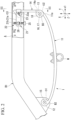
FIG. 1 is a side view showing a state where a leaf spring device of an embodiment is mounted onto a vehicle. -
FIG. 2 is a view showing a state before elastic deformation of a connection piece in the leaf spring device ofFIG. 1 . -
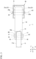
FIG. 3 is a view as seen along arrows of line III-III inFIG. 2 . -
FIG. 4 is a view as seen along arrows of line IV-IV inFIG. 2 . - Hereinafter, an embodiment of a leaf spring device will be described with reference to
FIG. 1 andFIG. 4 . - A
leaf spring device 1 of the present embodiment includes a leaf springmain body 11, afirst eye portion 12, asecond eye portion 13, and aconnection piece 14. - The
leaf spring device 1 is used by being assembled with a vehicle. In a state where a longitudinal direction X of the leaf springmain body 11 coincides with a front-rear direction of the vehicle, the central region of the leaf springmain body 11 in the longitudinal direction X supports an axle W. Thefirst eye portion 12 is attached to a vehicle body B1, and thesecond eye portion 13 is attached to the vehicle body B1 via theconnection piece 14. - The central region of the leaf spring
main body 11 in the longitudinal direction X supports the axle W and the leaf springmain body 11 is provided to be flexibly deformable upward. Note that the leaf springmain body 11 may support the axle W from above or may support the axle W from below. - The leaf spring
main body 11 is formed of, for example, fiber-reinforced resin. Examples of fibers contained in the fiber-reinforced resin include a glass fiber, a carbon fiber, and the like. In an example shown in the drawings, the leaf springmain body 11 is formed of fiber-reinforced resin containing glass fibers. The fibers are contained in the resin in a state of being substantially extended in the longitudinal direction X. - Note that the leaf spring
main body 11 may be formed of metal or the like. - In a state where the leaf spring
main body 11 is mounted onto a vehicle, the leaf springmain body 11 extends to become closer to an upper side toward outer end portions from the central region in the longitudinal direction X and is curved in a curved-surface shape protruding downward. At this time, the radius of curvature of the leaf springmain body 11 as seen in a width direction Y, which is orthogonal to a vertical direction Z and the longitudinal direction X, is larger than the radius of curvature of the leaf springmain body 11 before the mounting of the leaf springmain body 11 onto the vehicle. - Note that the leaf spring
main body 11 may extend straight in the longitudinal direction X in a state where the leaf springmain body 11 is mounted onto the vehicle. The leaf springmain body 11 may extend to become closer to a lower side toward the outer end portions from the central region in the longitudinal direction X and be curved in a curved-surface shape protruding upward. - The
first eye portion 12 is provided at a first end portion of the leaf springmain body 11 in the longitudinal direction X. Thesecond eye portion 13 is provided at a second end portion of the leaf springmain body 11 in the longitudinal direction X. Thefirst eye portion 12 and thesecond eye portion 13 are formed integrally with the leaf springmain body 11. - Note that the
first eye portion 12 and thesecond eye portion 13 may be formed separately from the leaf springmain body 11. - A
first fitting hole 15 that penetrates thefirst eye portion 12 in the width direction Y is formed in thefirst eye portion 12. Asecond fitting hole 16 that penetrates thesecond eye portion 13 in the width direction Y is formed in thesecond eye portion 13. - A first supporting shaft B2 fixed to the vehicle body B1 is fitted into the
first fitting hole 15 to be relatively rotatable, so that thefirst eye portion 12 is connected to the vehicle body B1 to be rotatable around afirst axis 01 extending in the width direction Y - The
connection piece 14 connects thesecond eye portion 13 and the vehicle body B1 to each other. - The
connection piece 14 is formed in a shape like a plate of which front and rear surfaces face the longitudinal direction X. As shown inFIG. 3 , theconnection piece 14 has, as seen in the longitudinal direction X, a rectangular shape that is long in the vertical direction Z and short in the width direction Y Theconnection piece 14 is formed to be elastically deformable (bendable) in the longitudinal direction X. - A
cutout portion 14a that penetrates theconnection piece 14 in the longitudinal direction X and is open on the lower side is formed at a lower end portion of theconnection piece 14.Third eye portions 18 are formed at both portions in the lower end portion of theconnection piece 14 that are on opposite sides in the width direction Y with thecutout portion 14a interposed therebetween. Thethird eye portion 18 is formed by rounding the above-described portion of thecutout portion 14a to have a ring-like shape that protrudes to an inner side in the longitudinal direction X, which is thefirst eye portion 12 side in the longitudinal direction X. Thethird eye portion 18 includes a thirdfitting hole 17 that penetrates thethird eye portion 18 in the width direction Y A second supporting shaft B3 is fitted into the third fitting holes 17 in a fixed state. - The
second eye portion 13 of the leaf springmain body 11 is inserted into thecutout portion 14a of theconnection piece 14 in a state of being positioned to be coaxial with thethird eye portions 18. The second supporting shaft B3 fixed to the third fitting holes 17 is fitted into the secondfitting hole 16 to be relatively rotatable, so that thesecond eye portion 13 is connected to theconnection piece 14 to be rotatable around a second axis O2 extending in the width direction Y - Here, an
adjustment member 21 that is connected to thevehicle body B 1 to be rotatable around a third axis O3 extending in the width direction Y, and amechanism portion 22 for upward and downward movement of theadjustment member 21 around the third axis O3 are provided. - As shown in
FIG. 4 , theadjustment member 21 includes a pair ofadjustment plates 21a that are provided at an interval in the width direction Y and of which the front and rear surfaces face the width direction Y Theadjustment member 21 is provided in an internal space A of a frame of the vehicle body B1. An upper end portion of theconnection piece 14 is inserted between the pair ofadjustment plates 21a. Theconnection piece 14 protrudes downward from the internal space A of the frame of the vehicle body B1. The upper end portion of theconnection piece 14 is formed in an annular shape and is disposed to be coaxial with the third axis O3. The upper end portion of theconnection piece 14 is fixed to theadjustment member 21. - A
fixation shaft 23 that penetrates both theadjustment member 21 and the upper end portion of theconnection piece 14 in the width direction Y is provided. Thefixation shaft 23 is disposed to be coaxial with the third axis O3. Each of bothend portions 23a of thefixation shaft 23 in the width direction Y is formed in a columnar shape and is supported by the frame of the vehicle body B1 to be rotatable around the third axis O3. - The
entire fixation shaft 23 excluding bothend portions 23a in the width direction Y has a non-circular shape (a triangular shape in the example shown in the drawings) as seen in the width direction Y Fitting holes each having a non-circular shape as seen in the width direction Y are formed in theadjustment member 21. A portion of thefixation shaft 23 that has a non-circular shape as seen in the width direction Y is fitted into the fitting holes of theadjustment member 21 in a fixed state. An inner peripheral surface of the upper end portion of theconnection piece 14 has a non-circular shape as seen in the width direction Y The portion of thefixation shaft 23 that has the non-circular shape as seen in the width direction Y is fitted into the upper end portion of theconnection piece 14. - Since the portion of the
fixation shaft 23 that has the non-circular shape as seen in the width direction Y is fitted into the fitting holes of theadjustment member 21 and into the upper end portion of theconnection piece 14, theadjustment member 21, the upper end portion of theconnection piece 14, and thefixation shaft 23 are restricted from relatively rotating around the third axis O3. In addition, when the leaf springmain body 11 is flexibly deformed upward, theconnection piece 14 is elastically deformed (bent) in the longitudinal direction X in accordance with a change in size of the leaf springmain body 11 in the longitudinal direction X. - The
mechanism portion 22 is provided at a portion of theadjustment member 21 that is separated from the third axis O3 in the longitudinal direction X. In the example shown in the drawings, themechanism portion 22 is separated from the third axis O3 while being closer to the inner side in the longitudinal direction X than the third axis O3 is. Note that themechanism portion 22 may be separated from the third axis O3 while being closer to an outer side in the longitudinal direction X than the third axis O3 is. - The
mechanism portion 22 includes abolt 25 and afemale screw member 26. - The
female screw member 26 is formed in a rectangular parallelepiped shape that is long in the width direction Y Thefemale screw member 26 has an upper-half semicircular shape as seen in the width direction Y As seen in the width direction Y, thefemale screw member 26 is defined by a flat lower surface that faces the lower side and a semicircular arc-shaped surface that protrudes upward. A through-hole 21b penetrating theadjustment plate 21a in the width direction Y is formed in each of the pair ofadjustment plates 21a. Both end portions of the semicircular arc-shaped surface of thefemale screw member 26 in the width direction Y are fitted into the through-holes 21b of the pair ofadjustment plates 21a such that the end portions can be slid around the central axis of the through-holes 21b. A screw hole penetrating thefemale screw member 26 in the vertical direction Z is formed in thefemale screw member 26, and thebolt 25 is screwed into the screw hole. A head portion of thebolt 25 abuts a lower surface of the frame of the vehicle body B1. - A
connection portion 11a of the leaf springmain body 11, at which the leaf springmain body 11 is connected to thesecond eye portion 13, is urged by an elastic restoring force of theconnection piece 14. In the present embodiment, at an initial stage of a process in which the leaf springmain body 11 is flexibly deformed upward, theconnection portion 11a is urged by the elastic restoring force of theconnection piece 14 in a direction (hereinafter, will be referred to as an initial movement direction) x1 in which theconnection portion 11a is displaced along the longitudinal direction X. - In the example shown in the drawings, the initial movement direction x1 is a direction toward the outer side (a right side) in the longitudinal direction X. In addition, in the process in which the leaf spring
main body 11 is flexibly deformed upward, theconnection portion 11a moves in the initial movement direction x1 until the leaf springmain body 11 is made straight in the longitudinal direction X. When the leaf springmain body 11 is curved to have a curved-surface shape that protrudes upward, that is, when a protruding portion of the leaf springmain body 11 is turned upside down, theconnection portion 11a is moved in a direction opposite to the initial movement direction x1 along the longitudinal direction X. At this time, theconnection portion 11a is urged in the initial movement direction x 1 by the elastic restoring force of theconnection piece 14. - Note that in a case where, in a state where the leaf spring
main body 11 is mounted onto the vehicle, the leaf springmain body 11 extends straight in the longitudinal direction X at an initial stage and in a case where the leaf springmain body 11 extends to become closer to the lower side toward the outer end portions from the central region in the longitudinal direction X and is curved in a curved-surface shape protruding upward, a direction in which theconnection portion 11a is displaced along the longitudinal direction X in a process in which the leaf springmain body 11 is flexibly deformed upward is always an inward (leftward) direction. - As shown in
FIG. 2 , theleaf spring device 1 is assembled with the vehicle in a state where no load is applied to theconnection piece 14. Thereafter, as the head portion of thebolt 25 is pinched and thebolt 25 is rotated relative to thefemale screw member 26 such that thefemale screw member 26 is lowered, as shown inFIG. 1 , theadjustment member 21 is lowered around the third axis O3 by thefemale screw member 26. Accordingly, a force that rotates the upper end portion of theconnection piece 14 around the third axis O3 in a counterclockwise direction (the direction opposite to the initial movement direction x1) as seen in the width direction Y is applied to theconnection piece 14 and theconnection piece 14 becomes about to move in the initial movement direction x1 as represented by a two-dot chain line inFIG. 1 . - At this time, the
third eye portions 18 of theconnection piece 14 are connected to the leaf springmain body 11 via the second supporting shaft B3 and thesecond eye portion 13. Therefore, as represented by a solid line inFIG. 1 , theconnection piece 14 is restrained from moving in the initial movement direction x1, and theconnection piece 14 is elastically deformed in the direction opposite to the initial movement direction x1. Accordingly, theconnection portion 11a of the leaf springmain body 11, at which the leaf springmain body 11 is connected to thesecond eye portion 13, is urged in the initial movement direction x1 by the elastic restoring force of theconnection piece 14. - As described above, according to the
leaf spring device 1 of the present embodiment, in a process in which the leaf springmain body 11 is flexibly deformed upward and theconnection portion 11a is displaced in the longitudinal direction X, flexible deformation of the leaf springmain body 11 is assisted by an urging force from theconnection piece 14 at an initial stage until amount of elastic displacement of theconnection piece 14 is decreased to cause an urging force applied from theconnection piece 14 to theconnection portion 11a in the initial movement direction to vanish, that is, until theconnection piece 14 is deformed into a shape represented by the two-dot chain line inFIG. 1 in the example shown in the drawings. Thereafter, as the flexible deformation of the leaf springmain body 11 progresses, elastic deformation of theconnection piece 14 followed by the deformation of the leaf springmain body 11 newly starts, so that theconnection portion 11a is urged by theconnection piece 14 in a direction opposite to the direction of the displacement along the longitudinal direction X. Note that a stage until amount of elastic displacement of theconnection piece 14 is decreased to cause the urging force applied from theconnection piece 14 to theconnection portion 11a in the initial movement direction to vanish may be referred to as a first stage of the above-described process. A stage after the first stage in which the flexible deformation of the leaf springmain body 11 progresses may be referred to as a second stage of the above-described process. That is, in the first stage of the above-described process, the flexible deformation of the leaf springmain body 11 is assisted by an urging force from theconnection piece 14, and in the second stage of the above-described process, theconnection portion 11a is urged by theconnection piece 14 in the direction opposite to the direction of the displacement along the longitudinal direction X. - Accordingly, a spring constant realized by the
leaf spring device 1 can be made low at an initial stage (the first stage of the above-described process) of a process in which the leaf springmain body 11 is flexibly deformed upward, and then the spring constant can be made high when flexible deformation of the leaf springmain body 11 progresses (the second stage of the above-described process). - The above-described action and effect can be achieved without, for example, changing the shape of the leaf spring
main body 11 to a specific shape or newly providing another spring member at the leaf springmain body 11, and thus it is possible to suppress the weight, the cost, and the like of theleaf spring device 1. For example, in a case where the leaf springmain body 11 is formed of fiber-reinforced resin or the like, it is not necessary to change a molding die, and thus the cost of theleaf spring device 1 can be reliably suppressed. - When the
adjustment member 21 is moved upward and downward around the third axis O3 by means of themechanism portion 22, the upper end portion of theconnection piece 14 moves in accordance with the upward and downward movement, so that theconnection piece 14 and the leaf springmain body 11 are elastically deformed. Accordingly, it is possible to easily adjust the amount and direction of elastic deformation of theconnection piece 14 such that theconnection piece 14 urges theconnection portion 11a in the initial movement direction x1. - For example, it is possible to adjust the amount and direction of elastic deformation of the
connection piece 14 by moving theadjustment member 21 upward and downward around the third axis O3 by means of themechanism portion 22 after theleaf spring device 1 is assembled with the vehicle in a state where no load is applied to theconnection piece 14. - Since the upper end portion of the
connection piece 14 is disposed to be coaxial with the third axis O3, theconnection piece 14 is easily elastically deformed as theadjustment member 21 moves upward and downward around the third axis O3, and thus it is possible to easily adjust the amount and direction of elastic deformation of theconnection piece 14. - The technical scope of the present invention is not limited to the above-described embodiments, and various modifications can be made within the scope not departing from the meaning of the present invention.
- For example, the
adjustment member 21 and themechanism portion 22 may be omitted. - The upper end portion of the
connection piece 14 may not be formed in an annular shape, and may be provided to be separated from the third axis O3. - Here, a method of adjusting the amount and direction of elastic deformation of the
connection piece 14 in a case where theconnection portion 11a moves inward in the longitudinal direction X in a process in which the leaf springmain body 11 is flexibly deformed upward will be described. Cases where theconnection portion 11a moves inward in the longitudinal direction X in a process in which the leaf springmain body 11 is flexibly deformed upward include a case where, in a state where the leaf springmain body 11 is mounted onto the vehicle, the leaf springmain body 11 extends straight in the longitudinal direction X at an initial stage and a case where the leaf springmain body 11 extends to become closer to the lower side toward the outer end portions from the central region in the longitudinal direction X and is curved in a curved-surface shape protruding upward. - First, the
female screw member 26 is raised by means of thebolt 25 and theadjustment member 21 is raised around the third axis O3 by means of thefemale screw member 26. Accordingly, a force in a clockwise direction around the third axis O3 as seen in the width direction Y, which is a direction shown inFIGS. 1 and2 , is applied to the upper end portion of theconnection piece 14, so that theconnection piece 14 is caused to move inward (leftward) in the longitudinal direction X. - At this time, the
third eye portions 18 of theconnection piece 14 are connected to the leaf springmain body 11 via the second supporting shaft B3 and thesecond eye portion 13. Therefore, theconnection piece 14 is restrained from moving inward in the longitudinal direction X, and theconnection piece 14 is elastically deformed outward in the longitudinal direction X. Accordingly, theconnection portion 11a is urged inward in the longitudinal direction X by the elastic restoring force of theconnection piece 14. - Furthermore, the components in the above-described embodiments can be appropriately replaced with well-known components within a range not departing from the meaning of the present invention, and the embodiments and modified examples described above may be appropriately combined.
- According to the present invention, it is possible to realize, while suppressing the weight, the cost, and the like of a leaf spring device, making a spring constant realized by the leaf spring device low at an initial stage of a process in which a leaf spring main body is flexibly deformed upward and then making the spring constant high when flexible deformation of the leaf spring main body progresses.
-
- 1: Leaf spring device
- 11: Leaf spring main body
- 11a: Connection portion
- 12: First eye portion
- 13: Second eye portion
- 14: Connection piece
- 21: Adjustment member
- 22: Mechanism portion
- B1: Vehicle body
- 01: First axis
- O2: Second axis
- O3: Third axis
- W: Axle
- X: Longitudinal direction
- Y: Width direction
- Z: Vertical direction
Claims (3)
- A leaf spring device comprising:a leaf spring main body;a first eye portion provided at a first end portion of the leaf spring main body in a longitudinal direction;a second eye portion provided at a second end portion of the leaf spring main body in the longitudinal direction; anda connection piece connecting the second eye portion and a vehicle body to each other, the connection piece being formed to be elastically deformable in the longitudinal direction,wherein the first eye portion is connected to the vehicle body to be rotatable around a first axis extending in a width direction of the leaf spring main body,the second eye portion is connected to the connection piece to be rotatable around a second axis extending in the width direction,a central region of the leaf spring main body in the longitudinal direction supports an axle,the leaf spring main body is provided to be flexibly deformable upward, anda connection portion of the leaf spring main body, at which the leaf spring main body is connected to the second eye portion, is urged by an elastic restoring force of the connection piece in a direction in which the connection portion is displaced along the longitudinal direction at an initial stage of a process in which the leaf spring main body is flexibly deformed upward.
- The leaf spring device according to Claim 1, further comprising:an adjustment member that is connected to the vehicle body to be rotatable around a third axis extending in the width direction,wherein a lower end portion of the connection piece is connected to the second eye portion,an upper end portion of the connection piece is fixed to the adjustment member, anda mechanism portion for upward and downward movement of the adjustment member around the third axis is provided at a portion of the adjustment member that is separated from the third axis in the longitudinal direction.
- The leaf spring device according to Claim 2,
wherein the upper end portion of the connection piece is formed in an annular shape and is disposed to be coaxial with the third axis.
Applications Claiming Priority (2)
| Application Number | Priority Date | Filing Date | Title |
|---|---|---|---|
| JP2021183979A JP7615008B2 (en) | 2021-11-11 | 2021-11-11 | Leaf Spring Device |
| PCT/JP2022/040877 WO2023085174A1 (en) | 2021-11-11 | 2022-11-01 | Leaf spring device |
Publications (2)
| Publication Number | Publication Date |
|---|---|
| EP4431317A1 true EP4431317A1 (en) | 2024-09-18 |
| EP4431317A4 EP4431317A4 (en) | 2025-02-26 |
Family
ID=86335976
Family Applications (1)
| Application Number | Title | Priority Date | Filing Date |
|---|---|---|---|
| EP22892673.9A Pending EP4431317A4 (en) | 2021-11-11 | 2022-11-01 | LEAF SPRING DEVICE |
Country Status (7)
| Country | Link |
|---|---|
| US (1) | US20240424848A1 (en) |
| EP (1) | EP4431317A4 (en) |
| JP (1) | JP7615008B2 (en) |
| KR (1) | KR102871785B1 (en) |
| CN (1) | CN118202167A (en) |
| MX (1) | MX2024005448A (en) |
| WO (1) | WO2023085174A1 (en) |
Family Cites Families (5)
| Publication number | Priority date | Publication date | Assignee | Title |
|---|---|---|---|---|
| AT516932A1 (en) | 2015-02-23 | 2016-09-15 | Hendrickson France S A S | Pen for a vehicle |
| DE102017206020B4 (en) | 2017-04-07 | 2022-09-08 | Ford Global Technologies, Llc | Leaf spring assembly for motor vehicles |
| DE102018201435B4 (en) | 2018-01-31 | 2021-11-11 | Ford Global Technologies, Llc | Axle suspension |
| DE102019209977A1 (en) | 2019-07-08 | 2021-01-14 | Ford Global Technologies, Llc | Axle suspension for a vehicle |
| JP7120646B2 (en) | 2019-12-17 | 2022-08-17 | 株式会社ユピテル | Driving support system and program |
-
2021
- 2021-11-11 JP JP2021183979A patent/JP7615008B2/en active Active
-
2022
- 2022-11-01 KR KR1020247014102A patent/KR102871785B1/en active Active
- 2022-11-01 US US18/708,112 patent/US20240424848A1/en active Pending
- 2022-11-01 EP EP22892673.9A patent/EP4431317A4/en active Pending
- 2022-11-01 WO PCT/JP2022/040877 patent/WO2023085174A1/en not_active Ceased
- 2022-11-01 MX MX2024005448A patent/MX2024005448A/en unknown
- 2022-11-01 CN CN202280071781.6A patent/CN118202167A/en active Pending
Also Published As
| Publication number | Publication date |
|---|---|
| KR20240070645A (en) | 2024-05-21 |
| CN118202167A (en) | 2024-06-14 |
| KR102871785B1 (en) | 2025-10-15 |
| MX2024005448A (en) | 2024-05-21 |
| EP4431317A4 (en) | 2025-02-26 |
| JP7615008B2 (en) | 2025-01-16 |
| US20240424848A1 (en) | 2024-12-26 |
| WO2023085174A1 (en) | 2023-05-19 |
| JP2023071307A (en) | 2023-05-23 |
Similar Documents
| Publication | Publication Date | Title |
|---|---|---|
| US8875348B2 (en) | Friction hinge system | |
| CN107975524B (en) | Mounting member for vehicle | |
| EP3694056A1 (en) | Connector and electronic device | |
| EP3173894A1 (en) | Bearing structure for vehicle pedal device and flanged bushing | |
| CN111752070B (en) | Optical unit | |
| US9931902B2 (en) | Stabilizer bushing and stabilizer-bar mounting device | |
| GB2524606A (en) | Power steering apparatus | |
| US10661627B2 (en) | Bracket | |
| KR20140117637A (en) | Stabilizer link and manufacturing method therefor | |
| JP6480000B1 (en) | Electronic control device for vehicle | |
| EP2808225A1 (en) | Steering column apparatus | |
| US20240424848A1 (en) | Leaf spring device | |
| KR20120140595A (en) | Thermal printer | |
| CN106660574B (en) | Steering column for motor vehicles | |
| EP2891394B1 (en) | Vibration reduction rib | |
| KR20160084395A (en) | Spring for sun visor and support device for sun visor | |
| EP4005901A1 (en) | Bearing bushing, preload structure, housing of transmission mechanism, and assembling structure of worm gear and worm | |
| EP4379230A1 (en) | Structure | |
| CN116001566A (en) | Bracket for a center console of a vehicle | |
| US11396318B2 (en) | Steering device | |
| KR102917840B1 (en) | Actuator and electronic equipment | |
| JP2005253272A (en) | Output shaft body support structure and electric motor | |
| JP2008287918A (en) | Electronic substrate module structure for vehicle | |
| CN210553945U (en) | Semi-axis support and car | |
| EP3572252A1 (en) | Support beam |
Legal Events
| Date | Code | Title | Description |
|---|---|---|---|
| STAA | Information on the status of an ep patent application or granted ep patent |
Free format text: STATUS: THE INTERNATIONAL PUBLICATION HAS BEEN MADE |
|
| PUAI | Public reference made under article 153(3) epc to a published international application that has entered the european phase |
Free format text: ORIGINAL CODE: 0009012 |
|
| STAA | Information on the status of an ep patent application or granted ep patent |
Free format text: STATUS: REQUEST FOR EXAMINATION WAS MADE |
|
| 17P | Request for examination filed |
Effective date: 20240506 |
|
| AK | Designated contracting states |
Kind code of ref document: A1 Designated state(s): AL AT BE BG CH CY CZ DE DK EE ES FI FR GB GR HR HU IE IS IT LI LT LU LV MC ME MK MT NL NO PL PT RO RS SE SI SK SM TR |
|
| DAV | Request for validation of the european patent (deleted) | ||
| DAX | Request for extension of the european patent (deleted) | ||
| A4 | Supplementary search report drawn up and despatched |
Effective date: 20250124 |
|
| RIC1 | Information provided on ipc code assigned before grant |
Ipc: F16F 1/30 20060101ALN20250121BHEP Ipc: F16F 1/26 20060101ALI20250121BHEP Ipc: F16F 15/073 20060101ALI20250121BHEP Ipc: F16F 1/22 20060101ALI20250121BHEP Ipc: F16F 1/18 20060101ALI20250121BHEP Ipc: B60G 11/10 20060101ALI20250121BHEP Ipc: B60G 11/04 20060101AFI20250121BHEP |