EP4431300A1 - Drying device, printing apparatus, and control method - Google Patents
Drying device, printing apparatus, and control method Download PDFInfo
- Publication number
- EP4431300A1 EP4431300A1 EP24161679.6A EP24161679A EP4431300A1 EP 4431300 A1 EP4431300 A1 EP 4431300A1 EP 24161679 A EP24161679 A EP 24161679A EP 4431300 A1 EP4431300 A1 EP 4431300A1
- Authority
- EP
- European Patent Office
- Prior art keywords
- air
- circulation path
- temperature
- drying device
- hot air
- Prior art date
- Legal status (The legal status is an assumption and is not a legal conclusion. Google has not performed a legal analysis and makes no representation as to the accuracy of the status listed.)
- Pending
Links
Images



Classifications
-
- B—PERFORMING OPERATIONS; TRANSPORTING
- B41—PRINTING; LINING MACHINES; TYPEWRITERS; STAMPS
- B41J—TYPEWRITERS; SELECTIVE PRINTING MECHANISMS, i.e. MECHANISMS PRINTING OTHERWISE THAN FROM A FORME; CORRECTION OF TYPOGRAPHICAL ERRORS
- B41J11/00—Devices or arrangements of selective printing mechanisms, e.g. ink-jet printers or thermal printers, for supporting or handling copy material in sheet or web form
- B41J11/0015—Devices or arrangements of selective printing mechanisms, e.g. ink-jet printers or thermal printers, for supporting or handling copy material in sheet or web form for treating before, during or after printing or for uniform coating or laminating the copy material before or after printing
- B41J11/002—Curing or drying the ink on the copy materials, e.g. by heating or irradiating
- B41J11/0022—Curing or drying the ink on the copy materials, e.g. by heating or irradiating using convection means, e.g. by using a fan for blowing or sucking air
- B41J11/00222—Controlling the convection means
-
- B—PERFORMING OPERATIONS; TRANSPORTING
- B41—PRINTING; LINING MACHINES; TYPEWRITERS; STAMPS
- B41J—TYPEWRITERS; SELECTIVE PRINTING MECHANISMS, i.e. MECHANISMS PRINTING OTHERWISE THAN FROM A FORME; CORRECTION OF TYPOGRAPHICAL ERRORS
- B41J11/00—Devices or arrangements of selective printing mechanisms, e.g. ink-jet printers or thermal printers, for supporting or handling copy material in sheet or web form
- B41J11/0015—Devices or arrangements of selective printing mechanisms, e.g. ink-jet printers or thermal printers, for supporting or handling copy material in sheet or web form for treating before, during or after printing or for uniform coating or laminating the copy material before or after printing
- B41J11/002—Curing or drying the ink on the copy materials, e.g. by heating or irradiating
- B41J11/0022—Curing or drying the ink on the copy materials, e.g. by heating or irradiating using convection means, e.g. by using a fan for blowing or sucking air
-
- B—PERFORMING OPERATIONS; TRANSPORTING
- B41—PRINTING; LINING MACHINES; TYPEWRITERS; STAMPS
- B41J—TYPEWRITERS; SELECTIVE PRINTING MECHANISMS, i.e. MECHANISMS PRINTING OTHERWISE THAN FROM A FORME; CORRECTION OF TYPOGRAPHICAL ERRORS
- B41J11/00—Devices or arrangements of selective printing mechanisms, e.g. ink-jet printers or thermal printers, for supporting or handling copy material in sheet or web form
- B41J11/0015—Devices or arrangements of selective printing mechanisms, e.g. ink-jet printers or thermal printers, for supporting or handling copy material in sheet or web form for treating before, during or after printing or for uniform coating or laminating the copy material before or after printing
- B41J11/002—Curing or drying the ink on the copy materials, e.g. by heating or irradiating
- B41J11/0022—Curing or drying the ink on the copy materials, e.g. by heating or irradiating using convection means, e.g. by using a fan for blowing or sucking air
- B41J11/00224—Curing or drying the ink on the copy materials, e.g. by heating or irradiating using convection means, e.g. by using a fan for blowing or sucking air comprising movable shutters, e.g. for redirection of an air flow
-
- B—PERFORMING OPERATIONS; TRANSPORTING
- B41—PRINTING; LINING MACHINES; TYPEWRITERS; STAMPS
- B41J—TYPEWRITERS; SELECTIVE PRINTING MECHANISMS, i.e. MECHANISMS PRINTING OTHERWISE THAN FROM A FORME; CORRECTION OF TYPOGRAPHICAL ERRORS
- B41J2/00—Typewriters or selective printing mechanisms characterised by the printing or marking process for which they are designed
- B41J2/005—Typewriters or selective printing mechanisms characterised by the printing or marking process for which they are designed characterised by bringing liquid or particles selectively into contact with a printing material
- B41J2/01—Ink jet
- B41J2/17—Ink jet characterised by ink handling
- B41J2/1714—Conditioning of the outside of ink supply systems, e.g. inkjet collector cleaning, ink mist removal
-
- F—MECHANICAL ENGINEERING; LIGHTING; HEATING; WEAPONS; BLASTING
- F26—DRYING
- F26B—DRYING SOLID MATERIALS OR OBJECTS BY REMOVING LIQUID THEREFROM
- F26B13/00—Machines and apparatus for drying fabrics, fibres, yarns, or other materials in long lengths, with progressive movement
- F26B13/10—Arrangements for feeding, heating or supporting materials; Controlling movement, tension or position of materials
- F26B13/108—Arrangements for feeding, heating or supporting materials; Controlling movement, tension or position of materials using one or more blowing devices, e.g. nozzle bar, the effective area of which is adjustable to the width of the material
-
- F—MECHANICAL ENGINEERING; LIGHTING; HEATING; WEAPONS; BLASTING
- F26—DRYING
- F26B—DRYING SOLID MATERIALS OR OBJECTS BY REMOVING LIQUID THEREFROM
- F26B21/00—Arrangements for supplying or controlling air or other gases for drying solid materials or objects
- F26B21/20—Circulating air or gases in closed cycles, e.g. wholly within the drying enclosure
- F26B21/25—Circulating air or gases in closed cycles, e.g. wholly within the drying enclosure partly outside the drying enclosure
-
- F—MECHANICAL ENGINEERING; LIGHTING; HEATING; WEAPONS; BLASTING
- F26—DRYING
- F26B—DRYING SOLID MATERIALS OR OBJECTS BY REMOVING LIQUID THEREFROM
- F26B21/00—Arrangements for supplying or controlling air or other gases for drying solid materials or objects
- F26B21/30—Controlling, e.g. regulating, parameters of gas supply
- F26B21/35—Temperature; Pressure
-
- F—MECHANICAL ENGINEERING; LIGHTING; HEATING; WEAPONS; BLASTING
- F26—DRYING
- F26B—DRYING SOLID MATERIALS OR OBJECTS BY REMOVING LIQUID THEREFROM
- F26B21/00—Arrangements for supplying or controlling air or other gases for drying solid materials or objects
- F26B21/30—Controlling, e.g. regulating, parameters of gas supply
- F26B21/37—Velocity of flow; Quantity of flow
-
- F—MECHANICAL ENGINEERING; LIGHTING; HEATING; WEAPONS; BLASTING
- F26—DRYING
- F26B—DRYING SOLID MATERIALS OR OBJECTS BY REMOVING LIQUID THEREFROM
- F26B3/00—Drying solid materials or objects by processes involving the application of heat
- F26B3/02—Drying solid materials or objects by processes involving the application of heat by convection, i.e. heat being conveyed from a heat source to the materials or objects to be dried by a gas or vapour, e.g. air
- F26B3/04—Drying solid materials or objects by processes involving the application of heat by convection, i.e. heat being conveyed from a heat source to the materials or objects to be dried by a gas or vapour, e.g. air the gas or vapour circulating over or surrounding the materials or objects to be dried
-
- B—PERFORMING OPERATIONS; TRANSPORTING
- B41—PRINTING; LINING MACHINES; TYPEWRITERS; STAMPS
- B41J—TYPEWRITERS; SELECTIVE PRINTING MECHANISMS, i.e. MECHANISMS PRINTING OTHERWISE THAN FROM A FORME; CORRECTION OF TYPOGRAPHICAL ERRORS
- B41J11/00—Devices or arrangements of selective printing mechanisms, e.g. ink-jet printers or thermal printers, for supporting or handling copy material in sheet or web form
- B41J11/0015—Devices or arrangements of selective printing mechanisms, e.g. ink-jet printers or thermal printers, for supporting or handling copy material in sheet or web form for treating before, during or after printing or for uniform coating or laminating the copy material before or after printing
- B41J11/002—Curing or drying the ink on the copy materials, e.g. by heating or irradiating
- B41J11/0024—Curing or drying the ink on the copy materials, e.g. by heating or irradiating using conduction means, e.g. by using a heated platen
-
- B—PERFORMING OPERATIONS; TRANSPORTING
- B41—PRINTING; LINING MACHINES; TYPEWRITERS; STAMPS
- B41J—TYPEWRITERS; SELECTIVE PRINTING MECHANISMS, i.e. MECHANISMS PRINTING OTHERWISE THAN FROM A FORME; CORRECTION OF TYPOGRAPHICAL ERRORS
- B41J11/00—Devices or arrangements of selective printing mechanisms, e.g. ink-jet printers or thermal printers, for supporting or handling copy material in sheet or web form
- B41J11/0015—Devices or arrangements of selective printing mechanisms, e.g. ink-jet printers or thermal printers, for supporting or handling copy material in sheet or web form for treating before, during or after printing or for uniform coating or laminating the copy material before or after printing
- B41J11/002—Curing or drying the ink on the copy materials, e.g. by heating or irradiating
- B41J11/0024—Curing or drying the ink on the copy materials, e.g. by heating or irradiating using conduction means, e.g. by using a heated platen
- B41J11/00242—Controlling the temperature of the conduction means
-
- B—PERFORMING OPERATIONS; TRANSPORTING
- B41—PRINTING; LINING MACHINES; TYPEWRITERS; STAMPS
- B41J—TYPEWRITERS; SELECTIVE PRINTING MECHANISMS, i.e. MECHANISMS PRINTING OTHERWISE THAN FROM A FORME; CORRECTION OF TYPOGRAPHICAL ERRORS
- B41J11/00—Devices or arrangements of selective printing mechanisms, e.g. ink-jet printers or thermal printers, for supporting or handling copy material in sheet or web form
- B41J11/0015—Devices or arrangements of selective printing mechanisms, e.g. ink-jet printers or thermal printers, for supporting or handling copy material in sheet or web form for treating before, during or after printing or for uniform coating or laminating the copy material before or after printing
- B41J11/002—Curing or drying the ink on the copy materials, e.g. by heating or irradiating
- B41J11/0024—Curing or drying the ink on the copy materials, e.g. by heating or irradiating using conduction means, e.g. by using a heated platen
- B41J11/00244—Means for heating the copy materials before or during printing
Definitions
- the present disclosure relates to a drying device, a printing apparatus, and a control method.
- U.S. Patent App. Pub. No. 2018/0222214 discloses a technique of discharging emulsion ink to a medium and then drying the emulsion ink using hot air to fix it to the medium.
- U.S. Patent App. Pub. No. 2018/0222214 also discloses a technique of circulating hot air. By circulating hot air, power of a heater that heats air can be saved.
- the present disclosure provides a technique of adjusting the temperature of inside air of a drying device in a shorter time.
- the present disclosure in a first aspect provides a drying device as specified in claims 1 to 14.
- the present disclosure in a second aspect provides a printing apparatus as specified in claim 15.
- the present disclosure in a third aspect provides a control method as specified in claim 16.
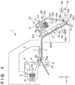
- Fig. 1 is a schematic view of a liquid discharge apparatus 1 according to an embodiment of the present disclosure.
- the liquid discharge apparatus 1 according to the embodiment is an inkjet printing apparatus that prints by discharging liquid ink to a printing medium.
- the present disclosure is applicable to even printing apparatuses and liquid discharge apparatuses of other types.
- arrows X and Y indicate horizontal directions crossing each other, and an arrow Z indicates a vertical direction.
- the X and Y directions are perpendicular to each other.
- printing not only includes the formation of significant information such as characters and graphics, but also broadly includes the formation of images, figures, patterns, and the like on a printing medium, or the processing of the medium, regardless of whether they are significant or insignificant, and regardless of whether they are so visualized as to be visually perceivable by humans.
- printing medium can be paper, cloth, a plastic film, or the like. More specifically, “printing medium” can be an ink absorbing medium such as paper, or an ink unabsorbing medium such as vinyl chloride. A discharged ink is assumed to be emulsion ink, but can be another type of ink.
- the printing apparatus 1 includes a conveying unit 6 that conveys a printing medium P.
- the conveying unit 6 includes a driving roller 6a that rotates by the driving force of a motor 6c, and a driven roller 6b that contacts the driving roller 6a under pressure.
- the printing medium P is a sheet medium, and supply and discharging of a sheet medium adopt a so-called roll-to-roll method of winding a sheet medium around rollers (not shown) different before and after printing.
- a cut sheet may be used as the printing medium P.
- the conveying unit 6 conveys the printing medium P in the Y direction (-Y direction).
- the driving roller 6a is a roller extending in the X direction.
- a platen 7 and a discharging head 2 facing the platen 7 are provided on the downstream side of the conveying unit 6 in the conveyance direction of the printing medium P.
- the printing medium P is conveyed between the platen 7 and the discharging head 2.
- the discharging head 2 is a printhead that discharges ink to the printing medium P on the platen 7.
- a carriage 3 supports the discharging head 2.
- the carriage 3 is guided by a guide 4 extending in the X direction and reciprocated in the X direction by a driving mechanism 5.
- the driving mechanism 5 is, for example, a belt transmission mechanism that includes an endless belt freely travelable in the X direction and uses a motor as a driving source.
- the carriage 3 is fixed to the endless belt.
- the printing apparatus 1 is a serial type printing apparatus in which the discharging head 2 is mounted on the carriage 3. Printing control is performed on the printing medium P by alternately repeating a conveyance operation (intermittent conveyance operation) of conveying the printing medium P by a predetermined amount by the conveying unit 6, and a printing operation during the stop of conveyance of the conveying unit 6.
- the printing operation is an operation of discharging ink from the discharging head 2 while moving the carriage 3 supporting the discharging head 2.
- the platen 7 may include a suction mechanism of sucking the printing medium P, and in the printing operation, may suck the printing medium P to prevent floating of the printing medium P.
- the printing apparatus 1 may be a full-line type printing apparatus in which the discharging head 2 extends in the X direction without providing the carriage 3.
- a hot air blowing device 8 is provided at a position upstream of the discharging head 2 in the conveyance direction of the printing medium P.
- the hot air blowing device 8 includes a blowing unit 81 that blows air, and a heating unit 82 that heats the air blown from the blowing unit 81.
- the hot air blowing device 8 blows hot air toward a region (surface of the printing medium P) between the platen 7 and the discharging head 2. This promotes evaporation of water contained in ink discharged to the surface of the printing medium P on the platen 7, and promotes drying of the ink and fixation to the printing medium P.
- the blowing unit 81 is an electric fan
- the heating unit 82 is a coil type electrothermal transducer.
- the blowing mechanism of the blowing unit 81 and the heat source of the heating unit 82 are not limited to them.
- a drying device 10 is provided at a position downstream of the discharging head 2 in the conveyance direction of the printing medium P.
- the drying device 10 shares the conveying unit 6 as the conveying mechanism of the printing medium P with the printing mechanism (discharging head 2, carriage 3, and the like), and is arranged at a position where the drying device 10 faces a guide unit 9 configured to guide conveyance of the printing medium P.
- the guide unit 9 guides the printing medium P obliquely downward.
- the drying device 10 is a fixing device that promotes drying of ink and fixation to the printing medium P by blowing hot air to the printing medium P that bears ink discharged from the discharging head 2 and is conveyed on the guide unit 9.
- the drying device 10 includes a hot air blowing unit 11 and a passage forming unit 14.
- the hot air blowing unit 11 is a mechanism that includes a blowing unit 12 configured to blow air, and a heating unit 13 configured to heat air, and generates hot air.
- the blowing unit 12 is an electric fan
- the heating unit 13 is a coil type electrothermal transducer.
- the blowing mechanism of the blowing unit 12 and the heat source of the heating unit 13 are not limited to them.
- the heating unit 13 is arranged on the downstream side of the blowing unit 12 in the blowing direction, and heats air blown from the blowing unit 12.
- the heating unit 13 may be arranged on the upstream side of the blowing unit 12.
- the passage forming unit 14 is a member that forms, between the hot air blowing unit 11 and a region R on the conveyance path (on RT0) of the conveying unit 6, a circulation path RT1 through which air blown from the hot air blowing unit 11 is circulated.
- the region R is a section of part of the conveyance path RT0 demarcated by the guide unit 9, and is a section facing the bottom of the drying device 10.
- the passage forming unit 14 includes a chamber 14a that incorporates the hot air blowing unit 11 and demarcates an internal space SP, partitions 14b formed inside the chamber 14a, a blow-off plate 14c, and a cover member 14d.
- the blow-off plate 14c is a perforated plate in which many holes are formed.
- the circulation path RT1 is demarcated by the chamber 14a, the partitions 14b, and the surface of the guide unit 9. Air blown from the blowing unit 12 is circulated from the heating unit 13 in the order of the blow-off plate 14c, the surface of the guide unit 9 or the printing medium P, and the blowing unit 12.
- the circulation path RT1 has an introduction portion RTi to which air outside the circulation path (outside RT1) is introduced, and an exhaust portion RTo from which air inside the circulation path (inside RT1 indicated by a two-dot broken line) is exhausted.
- the chamber 14a forms, together with the guide unit 9, an airtight space excluding the introduction portion RTi and the exhaust portion RTo.
- the introduction portion RTi is an opening portion formed at the upstream end of the circulation path RT1 in the conveyance direction of the printing medium P.
- the exhaust portion RTo is an opening portion formed at the downstream end of the circulation path RT1 in the conveyance direction of the printing medium P.
- Hot air is blown from the hot air blowing unit 11 through the blow-off plate 14c to the printing medium P conveyed on the guide unit 9.
- the temperatures of ink and the printing medium P rise, water and a solvent contained in the ink evaporate, and emulsion ink forms a film.
- Part of the hot air blown from the hot air blowing unit 11 forms a flow circulating through the circulation path RT1. Since the already heated hot air circulates, the power consumption of the heating unit 13 can be reduced.
- the drying device 10 includes temperature sensors 15a to 15c.
- the temperature sensor 15a is arranged in the internal space SP, and especially on the downstream side of the heating unit 13 and the upstream side of the region R or blow-off plate 14c in the flow direction of the circulating flow within the circulation path RT1.
- the temperature sensor 15a can detect the temperature of hot air blown to the printing medium P.
- the temperature sensor 15b is arranged on the inner wall surface of the circulation path RT1 that is formed by the chamber 14a, and can detect the temperature of the inner wall surface.
- the temperature sensor 15c is arranged in the region R and can detect the temperature of the region R.
- the three temperature sensors 15a to 15c are provided and arranged at different positions in the embodiment, but one temperature sensor is sufficient.
- the drying device 10 includes an adjusting unit 16.
- the adjusting unit 16 adjusts the ratio between inside air circulating through the circulation path RT1 and air outside the circulation path RT1 that is introduced into the circulation path RT1.
- the adjusting unit 16 adjusts the amount of air outside the circulation path RT1 (outside the chamber 14a) that is supplied to the blowing unit 12.
- the adjusting unit 16 adjusts the exhaust amount of inside air of the circulation path RT1 that is exhausted from the circulation path RT1.
- the flow rate of inside air exhausted from the exhaust portion RTo is almost equal to that of outside air introduced from the introduction portion RTi.
- the introduction amount of outside air to the circulation path RT1 increases and the circulating air amount decreases. That is, the amount of outside air supplied to the blowing unit 12 increases.
- the exhaust amount is decreased, the introduction amount of outside air to the circulation path RT1 decreases, and the circulating air amount increases. That is, the amount of outside air supplied to the blowing unit 12 decreases.
- the ratio between inside air circulating through the circulation path RT1 and air outside the circulation path RT1 that is introduced into the circulation path RT1 can be adjusted.
- the temperature of air in the internal space SP becomes relatively low at a high ratio of outside air, and relatively high at a low ratio of outside air.
- the increase and decrease of the temperature of air in the internal space SP can be controlled.
- the temperature of inside air of the drying device 10 can be adjusted in a shorter time.
- the adjusting unit 16 adjusts the exhaust amount by changing the opening amount of the exhaust portion RTo by the displacement of a movable member 16a.
- the movable member 16a is a plate-like flapper pivotally provided around a shaft CT in the X direction, and pivots by the driving force of an actuator (here, a motor) 16c.
- the position of the movable member 16a is detected by a position detection sensor 16d.
- the position detection sensor 16d is, for example, a potentiometer or a rotary encoder that detects the pivot amount of the movable member 16a.
- the position of the movable member 16a that is, the opening amount of the exhaust portion RTo can be controlled more accurately by controlling the actuator 16c based on the detection result of the position detection sensor 16d. It can also be controlled to decrease the temperature of hot air (decrease the heat generation amount of the heating unit 13) when a temperature of hot air set by the user is high, but the position detection sensor 16d detects that the opening amount of the exhaust portion RTo is small.
- the position detection sensor 16d may be a microswitch that detects a position where an opening formed by the movable member 16a is large and a position where the opening is small.
- the position of the movable member 16a is held by a holding unit 16b.
- the holding unit 16b is a lock mechanism that locks the position of the movable member 16a so as not to unnecessarily displace it.
- the holding unit 16b is, for example, a torque limiter provided on the shaft CT.
- the driving force of the actuator 16c exceeds a predetermined torque of the torque limiter, the movable member 16a pivots. Even if an external force smaller than the predetermined torque acts on the movable member 16a, the position of the movable member 16a is held.
- the holding unit 16b can continuously maintain the position of the movable member 16a, that is, the opening amount of the exhaust portion RTo.
- the cover member 14d covers the exhaust portion RTo, and has an opening through which exhausted air passes.
- the cover member 14d can prevent entrance of dust or the like into the circulation path RT1.
- the cover member 14d covers even the movable member 16a.
- the cover member 14d can protect the movable member 16a.
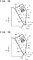
- Figs. 2A and 2B are views for explaining the operation of the adjusting unit 16.
- Fig. 2A shows a state in which the movable member 16a is fully open, and the opening ratio of the exhaust portion RTo is 100%.
- the opening ratio of the exhaust portion RTo is 100%, as shown in Fig. 2A , high-temperature inside air easily flows out, but the amount of outside air taken from the introduction portion RTi increases in proportion. As a result, the temperature of inside air of the drying device 10 can be quickly decreased.
- the opening ratio here is 100% in the embodiment, but is not limited to this as long as the opening ratio is much higher than that in the fully closed state of the movable member 16a (to be described later).
- Fig. 2A The operation in Fig. 2A is advantageous when the temperature of inside air of the drying device 10 is decreased.
- the drying device 10 is turned off to decrease the temperature for the convenience of user work.
- the movable member 16a is displaced in the open direction to widen the opening of the exhaust portion RTo, as shown in Fig. 2B . It is effective to rotate the blowing unit 12 especially at a higher speed.
- Power supply to the heating unit 13 is decreased, or supply of power is stopped.
- the circulation rate of hot air can be decreased to take a larger amount of outside air in the circulation path RT1, and quickly decrease the temperature of the whole drying device 10. As a result, the standby time until the user starts work can be shortened, improving the convenience.
- the operation in Fig. 2A is also advantageous when the temperature setting of a new print job is lower than the current fixing condition.
- the temperature of the whole drying device 10 can be quickly decreased, and the time until a new print job is started can be shortened, improving the throughput.
- Fig. 2B shows a state in which the movable member 16a is fully closed (initial state), and the opening ratio of the exhaust portion RTo is 10% or less.
- the opening ratio of the exhaust portion RTo is 10% or less, as shown in Fig. 2B , low-temperature inside air hardly flows out, but the amount of outside air taken from the introduction portion RTi also decreases in proportion.
- the circulation rate of inside air can be increased to quickly increase the temperature of inside air by heating of the heating unit 13. Since inside air circulates and is repetitively heated by the heating unit 13, the power consumption of the heating unit 13 can be reduced.
- the opening ratio is 10% in the embodiment, but is not limited to this. For example, as the flow rate of the blowing unit 12 is higher, the opening ratio needs to be lower.
- Fig. 2B The operation in Fig. 2B is suitable when the temperature of inside air is increased as in turning on the drying device 10.
- the opening of the exhaust portion RTo is narrowed by the movable member 16a, the blowing unit 12 is rotated, and power is supplied to the heating unit 13.
- the circulation rate of hot air can be increased to quickly increase the temperature of the whole drying device 10 and obtain stable hot air in a short time.
- the standby time until ink is dried and fixed to the printing medium P after the start of printing can be shortened, implementing power reduction and high throughput.
- the operation in Fig. 2B is also advantageous when the temperature setting of a new print job is higher than the current fixing condition.
- the temperature of the whole drying device 10 can be quickly increased, and the time until a new print job is started can be shortened, improving the throughput.
- the operations in Figs. 2A and 2B can be performed until, for example, the detection result of the temperature sensor 15a represents a predetermined temperature.
- the detection result of the temperature sensor 15b or 15c may also be used as a criterion instead of the detection result of the temperature sensor 15a or as an additional condition.
- the temperature of the chamber 14a is in transition asymptotically to the temperature of hot air, and hot air heated by the heating unit 13 is cooled by the inner wall of the chamber 14a.
- the operation in Fig. 2B is continued until the detection result of the temperature sensor 15b provided on the inner wall of the chamber 14a exhibits a predetermined temperature.
- the temperature of the whole drying device 10 becomes steady, and more stable hot air can be supplied to the printing medium P.
- Whether the quantity of heat acting on the printing medium P satisfies an intended quantity of heat can be determined based on whether the detection result of the temperature sensor 15c represents a predetermined temperature. By using the detection result of the temperature sensor 15c as a criterion, an intended quantity of heat can be applied to the printing medium P.
- the printing apparatus 1 includes the control unit 20 that controls the printing apparatus 1.
- the control unit 20 includes a processing unit 21, a storage unit 22, and an input/output interface (I/O) 23.
- the processing unit 21 is formed from one or more processors, and controls the printing apparatus 1 by executing a control program stored in the storage unit 22. More specifically, for example, the processing unit 21 obtains the detection result of a sensor 33 to perform driving control of an actuator 34, a heat generation element 35, the discharging head 2, and the drying device 10.
- the storage unit 22 is formed from one or more storage devices, and stores the control program and various data.
- the storage devices include semiconductor memories such as a RAM and a ROM, and a magnetic storage device such as a hard disk.
- the I/O 23 relays input/output of signals between the processing unit 21 and an external device.
- An operation panel 311 is an input device that accepts an input from the user.
- the operation panel 311 may be a touch panel having a display function of providing information to the user.
- the user can set a temperature and amount of hot air in the drying device 10 by inputting them to the operation panel 311.
- the temperature of hot air may be set by input of the user.
- temperature information of hot air that is determined in advance in accordance with the type of the printing medium P may be stored in the storage unit 22, and a temperature corresponding to the type of the printing medium P used may be read out from the temperature information and set.
- An external terminal 321 is a host computer such as a personal computer, and transmits to the control unit 20 an image or the like to be printed on the printing medium P by the printing apparatus 1.
- the sensor 33 includes various sensors (for example, the position detection sensor of the carriage 3 and the rotation amount sensor of the driving roller 6a).
- the actuator 34 includes the motor 6c, the driving motor of the blowing unit 81, and the driving motor of the driving mechanism 5.
- the heat generation element 35 includes each heat generation element of the heating unit 82.
- the sensors of the drying device 10 include the temperature sensors 15a to 15c, and the position detection sensor 16d.
- the actuators of the drying device 10 include the actuator (motor) 16c, the driving motor of the blowing unit 12, and the heat generation element of the heating unit 13.
- FIG. 4 is a flowchart showing a processing example of the control unit 20 regarding control of the drying device 10, and a flowchart especially showing a processing example when the temperature of inside air of the drying device 10 is changed.
- step S1 it is determined whether a temperature increase condition is established. If the temperature increase condition is established, the process advances to step S2; if NO, to step S6.
- the temperature increase condition can include a temperature increase instruction from the user.
- the temperature increase instruction from the user includes an ON operation to the drying device 10, an instruction to the operation panel 311, and an instruction from the external terminal 321. For each instruction, a target temperature is set.
- the instruction from the external terminal 321 includes an execution instruction to a print job (discharge operation instruction to the discharging head 2).
- the temperature increase condition is established.
- the temperature of hot air can be set in accordance with the type of the printing medium P.
- step S2 temperature increase processing is executed.
- the drying device 10 is controlled to increase the ratio of inside air in the internal space SP.
- the movable member 16a of the adjusting unit 16 is fully closed.
- the hot air blowing unit 11 is driven to increase the temperature of hot air blown from the hot air blowing unit 11.
- the blowing unit 12 is driven to blow air, and power is supplied to the heating unit 13 to heat air from the blowing unit 12.
- step S3 it is determined whether the temperature of air in the internal space SP has reached a target temperature. If the temperature of air in the internal space SP has reached the target temperature, the process advances to step S5. This determination is made using the detection results of the temperature sensors 15a to 15c.
- the detection results used may be the detection results of all the sensors or the detection result of one of them.
- the target temperature may be equal or close to the temperature of hot air at the time of subsequent ink drying.
- step S4 the temperature increase processing ends, and the process advances to step S5.
- step S5 the blowing unit 12 and the heating unit 13 are driven in accordance with the condition of subsequent ink drying.
- the movable member 16a of the adjusting unit 16 is maintained in the fully closed state, but may be displaced to a position set in accordance with the drying condition or the like.
- step S6 it is determined whether a temperature decrease condition is established. If the temperature decrease condition is established, the process advances to step S7; if NO, the processing in Fig. 4 ends.
- the temperature decrease condition can include a temperature decrease instruction from the user, and a condition based on the state of the printing apparatus 1.
- the temperature decrease instruction from the user includes an OFF operation to the drying device 10, an instruction to the operation panel 311, and an instruction from the external terminal 321. For each instruction, a target temperature is set.
- the instruction from the external terminal 321 includes an execution instruction to a print job (discharge operation instruction to the discharging head 2).
- the temperature decrease condition is established.
- the temperature of hot air can be set in accordance with the type of the printing medium P.
- the condition based on the state of the printing apparatus 1 includes generation of maintenance.
- the generation of maintenance includes replacement work of the printing medium P, replacement work of the discharging head 2, and recovery work of an error (for example, cancellation work of a generated jam).
- step S7 temperature decrease processing is executed.
- the drying device 10 is controlled to increase the ratio of outside air in the internal space SP.
- the movable member 16a of the adjusting unit 16 is fully opened.
- the hot air blowing unit 11 is driven to decrease the temperature of hot air blown from the hot air blowing unit 11.
- the blowing unit 12 is driven to blow air, and power supplied to the heating unit 13 is decreased or supply of power is stopped.
- step S8 it is determined whether the temperature of air in the internal space SP has reached a target temperature. If the temperature of air in the internal space SP has reached the target temperature, the process advances to step S9. This determination is made using the detection results of the temperature sensors 15a to 15c. The detection results used may be the detection results of all the sensors or the detection result of one of them.
- the target temperature may be set in accordance with the temperature decrease condition determined to be established in step S6. For example, in the OFF operation of the drying device 10, room temperature may be set as the target temperature. For example, in generation of maintenance, a temperature (from room temperature to almost the body temperature) at which the operator can work may be set as the target temperature. For example, in execution of a print job, the target temperature may be equal or close to the temperature of hot air at the time of ink drying in the print job.
- step S9 the temperature decrease processing ends, and the process advances to step S10.
- step S10 it is determined whether the temperature decrease condition determined to be established in step S6 is for a new print job. If it is determined that the temperature decrease condition is for a new print job, the process advances to step S5, the blowing unit 12 and the heating unit 13 are driven in accordance with subsequent ink drying, and the position of the movable member 16a of the adjusting unit 16 is set. If it is determined that the temperature decrease condition is not for a new print job, the process advances to step S11 to stop the drying device 10.
- the temperature of inside air of the drying device 10 can be adjusted in a shorter time by adjusting the ratio between inside air circulating through the circulation path RT1 by the adjusting unit 16 and outside air introduced into the circulation path RT1.
- the driving method of an adjusting unit 16 can be not electrical driving but manual driving.
- manual driving a printing apparatus can be manufactured at low cost, a motor or the like need not be provided, and a compact printing apparatus 1 can be implemented.
- Fig. 5 shows an example of this arrangement.
- an operation member 16e is coupled to a movable member 16a, and the user can displace the movable member 16a by externally operating the operation member 16e.
- an actuator 16c nor a sensor 16d is provided.
- the user may determine establishment of a temperature increase condition or establishment of a temperature decrease condition, and operate the movable member 16a.
- a control unit 20 may inform the user via an operation panel 311 of establishment of a temperature increase condition or establishment of a temperature decrease condition, and prompt the user to operate the movable member 16a.
- both electrical driving and manual driving may be adopted as the driving method of the adjusting unit 16.
- the actuator 16c and the sensor 16d are provided in addition to the operation member 16e.
- Control of the adjusting unit 16 is basically automatic control, and the user may adjust the position of the movable member 16a by operating the operation member 16e, as needed.
- An adjusting unit 16 may be not a mechanism that changes the opening ratio of an exhaust portion RTo, like the first embodiment, but an external blowing mechanism that blows air in the exhaust direction of the exhaust portion RTo at a position adjacent to the exhaust portion RTo.
- Figs. 6A and 6B show an example of this arrangement.
- an adjusting unit 17 is provided instead of the adjusting unit 16.
- the adjusting unit 17 is an external blowing mechanism (downflow unit) including a passage forming unit 17a and a blowing unit 17b.
- the passage forming unit 17a forms an air path having an inlet open at a portion adjacent to an introduction portion RTi, and an outlet open at a portion adjacent to the exhaust portion RTo.
- the blowing unit 17b is an electric fan that is arranged inside the air path and especially near the outlet of the air path, and blows air to the vicinity of the exhaust portion RTo in the exhaust direction of the exhaust portion RTo.
- the blowing unit 17b is covered with a cover member 14d.
- a drying device 10 includes a cooling unit 30 that cools the adjusting unit 17.
- the cooling unit 30 includes a blowing unit 31, and a duct 32 that guides air blown from the blowing unit 31 to the blowing unit 17b. Outside air can be blown by the blowing unit 31 to the blowing unit 17b to cool the blowing unit 17b. Temperature rise of the blowing unit 17b by hot air exhausted from the exhaust portion RTo can be suppressed.
- a control unit 20 can control the air amount of the blowing unit 17b.
- Fig. 6A shows a control example of the adjusting unit 17 in temperature decrease processing (step S7 in Fig. 4 ).
- the blowing unit 17b is driven to increase the flow rate (increase the rotational speed of the electric fan). If the flow rate of the blowing unit 17b is increased, hot air exhausted from the exhaust portion RTo is easily exhausted under the influence of the flow resistance of air from the blowing unit 17b. Resultantly, the amount of outside air taken into the introduction portion RTi can be increased to increase the ratio of outside air in an internal space SP and promote the decrease of the temperature of inside air of the drying device 10.
- Fig. 6B shows a control example of the adjusting unit 17 in temperature increase processing (step S2 in Fig. 4 ).
- the blowing unit 17b is driven to decrease the flow rate (decrease the rotational speed of the electric fan).
- Hot air exhausted from the exhaust portion RTo is almost free from the influence of the flow resistance of air from the blowing unit 17b and is hardly exhausted.
- the amount of outside air taken into the introduction portion RTi can be decreased to increase the circulation rate of hot air and promote the increase of the temperature of inside air of the drying device 10.
- An arrangement example in Fig. 7 can also be employed as another example of the external blowing mechanism that blows air in the exhaust direction of the exhaust portion RTo at a position adjacent to the exhaust portion RTo.
- An adjusting unit 17' is a blowing unit and an electric fan arranged on the downstream side of the exhaust portion RTo in the conveyance direction of a printing medium P, and is covered with the cover member 14d.
- the drying device 10 includes the cooling unit 30 that cools the adjusting unit 17'.
- the exhaust direction of the adjusting unit 17' coincides with the exhaust direction of hot air from the exhaust portion RTo.
- a larger amount of hot air is exhausted from the exhaust portion RTo owing to the flow resistance, and a larger amount of outside air is taken into the introduction portion RTi.
- the control unit 20 can control the flow rate of the adjusting unit 17'.
- temperature decrease processing step S7 in Fig. 4
- the control unit 20 controls the flow rate to be high. Exhaust from the exhaust portion RTo is promoted to take a larger amount of outside air into the introduction portion RTi and decrease the temperature of inside air of the drying device 10.
- temperature increase processing step S2 in Fig. 4
- the control unit 20 controls the flow rate to be low or stops the flow. Exhaust from the exhaust portion RTo is suppressed to decrease the amount of outside air taken into the introduction portion RTi, increase the circulation rate of hot air, and promote the increase of the temperature of inside air of the drying device 10.
- the adjusting units 17 and 17' are configured to exhaust outside air.
- exhausted air may be, for example, air discharged from another place in a printing apparatus 1, or air (hot air) in the internal space SP.
- An adjusting unit may adjust the introduction amount of outside air to a circulation path RT1.
- Figs. 8A and 8B show an example of this arrangement.
- a chamber 14a has an opening portion 14e.
- the opening portion 14e is formed at an upstream-side portion of a blowing unit 12 on the downstream side of a region R or a blow-off plate 14c in the flow direction of a circulating flow.
- the opening portion 14e allows the circulation path RT1 to communicate with the outside.
- An adjusting unit 18 includes movable members 18a that change the opening amount of the opening portion 14e.
- a plurality of movable members 18a are provided and form a louver to open/close the opening portion 14e.
- Each movable member 18a is a plate-like flapper pivotally provided around a shaft CT in the X direction, and pivots by the driving force of an actuator (here, a motor) 18c.
- the position of the movable member 18a is detected by a position detection sensor 18d.
- the position detection sensor 18d is, for example, a potentiometer or a rotary encoder that detects the pivot amount of the movable member 18a.
- the position of the movable member 18a that is, the opening amount of the opening portion 14e can be controlled more accurately by controlling the actuator 18c based on the detection result of the position detection sensor 18d.
- the position detection sensor 18d may be a microswitch that detects opening/closing by the movable member 18a. It can also be controlled to decrease the temperature of hot air (decrease the heat generation amount of a heating unit 13) when a temperature of hot air set by the user is high, but the position detection sensor 18d detects that the opening amount of the opening portion 14e is small.
- the position of the movable member 18a is held by a holding unit 18b.
- the holding unit 18b is a lock mechanism that locks the position of the movable member 18a so as not to unnecessarily displace it.
- the holding unit 18b is, for example, a torque limiter provided on the shaft CT.
- the driving force of the actuator 18c exceeds a predetermined torque of the torque limiter, the movable member 18a pivots. Even if an external force smaller than the predetermined torque acts on the movable member 18a, the position of the movable member 18a is held.
- the holding unit 18b can continuously maintain the position of the movable member 18a, that is, the opening amount of the opening portion 14e.
- the opening portion 14e is covered with a cover member 14f having an opening through which air can pass.
- the movable members 18a are also covered with the cover member 14f.
- the control unit 20 can control the adjusting unit 18.
- each movable member 18a is displaced to increase the opening amount of the opening portion 14e.
- Fig. 8A shows a state in which each movable member 18a is fully open, and the opening ratio of the opening portion 14e is 100%.
- the opening ratio of the opening portion 14e is 100%, as shown in Fig. 8A , the ratio of outside air in the internal space SP can increase to promote the decrease of the temperature of inside air of the drying device 10.
- the opening ratio is 100% in the embodiment, but is not limited to this and suffices to be much higher than that in the fully closed state of the opening portion 14e (to be described later).
- each movable member 18a is displaced to decrease the opening amount of the opening portion 14e.
- Fig. 8B shows a state (initial state) in which each movable member 18a is fully closed, and the opening ratio of the opening portion 14e is 0%.
- the opening ratio of the opening portion 14e is 0%, the circulation rate of inside air can be increased to promote the increase of the temperature of inside air of the drying device 10.
- the power consumption of the heating unit 13 can be reduced.
- the opening ratio is 0% in the embodiment, but even if the opening portion 14e is slightly open, it can be regarded as substantially 0% as long as the opening portion 14e is narrow.
- the movable member 18a may be manually displaced.
- the introduction portion RTi may be opened/closed.
- the area of the flow channel of the introduction portion RTi may be adjusted by a valve or the like.
- a chamber 14a has an opening portion 14e'.
- the opening portion 14e' is formed at an upstream-side portion of a blowing unit 12 on the downstream side of a region R or a blow-off plate 14c in the flow direction of a circulating flow.
- the opening portion 14e' allows a circulation path RT1 to communicate with the outside.
- An adjusting unit 18' includes a movable member 18e that changes the opening amount of the opening portion 14e'.
- the movable member 18e is a plate-like member provided to be translatable, and forms a shutter to open/close the opening portion 14e'.
- the movable member 18e may be displaced by an actuator such as a motor, and a sensor that detects the position of the movable member 18e may be provided.
- a control unit 20 can control the adjusting unit 18'.
- the control unit 20 displaces the movable member 18e to increase the opening amount of the opening portion 14e'.
- Fig. 9A shows a state in which the movable member 18e is almost fully open, and the opening ratio of the opening portion 14e' is 90 or more.
- the opening ratio of the opening portion 14e' is high, the ratio of outside air in an internal space SP can increase to promote the decrease of the temperature of inside air of the drying device 10.
- the opening ratio is 90% in the embodiment, but is not limited to this and suffices to be much higher than that in the fully closed state of the opening portion 14e' (to be described later).
- each movable member 18e is displaced to decrease the opening amount of the opening portion 14e'.
- Fig. 9B shows a state (initial state) in which the movable member 18e is fully closed, and the opening ratio of the opening portion 14e' is 0%.
- the opening ratio of the opening portion 14e' is 0%, the circulation rate of inside air can be increased to promote the increase of the temperature of inside air of the drying device 10. Further, the power consumption of a heating unit 13 can be reduced.
- the opening ratio is 0% in the embodiment, but even if the opening portion 14e' is slightly open, it can be regarded as substantially 0% as long as the opening portion 14e' is narrow.
- the movable member 18e may be manually displaced. Also, a holding unit that holds the position of the movable member 18e may be provided. A movable member that is displaced by translation, as in the fifth embodiment, may be adopted as a movable member that adjusts the exhaust amount of an exhaust portion RTo, as in the first embodiment.
- a hot air blowing device 8 may also be used as the adjusting unit of a drying device 10.
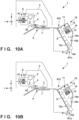
- Figs. 10A and 10B are views for explaining this arrangement.
- a blowing unit 81 of the hot air blowing device 8 is driven, blown air passes through a platen 7 and a discharging head 2 and reaches an introduction portion RTi. That is, the blowing unit 81 can be used as an external blowing unit that blows air toward the introduction portion RTi.
- the heat generation amount of a heating unit 82 as an external heating unit can be adjusted to adjust the temperature of air blown to the introduction portion RTi.
- step S7 in Fig. 4 the air amount of the blowing unit 81 is relatively increased (electric fan is driven at a high rotational speed) to relatively decrease power supply of the heating unit 82 or stop supply of power.
- Fig. 10A shows an example of this state.
- the ratio of outside air flowing into a blowing unit 12 can be increased by blowing air from the blowing unit 81 of the hot air blowing device 8 to the introduction portion RTi.
- the heating unit 82 stops heat generation.
- the ratio of outside air in an internal space SP can increase to promote the decrease of the temperature of inside air of the drying device 10.
- step S2 in Fig. 4 the air amount of the blowing unit 81 is relatively decreased (electric fan is driven at a low rotational speed) to relatively increase power supply of the heating unit 82.
- Fig. 10B shows an example of this state.
- the flow rate of air blown from the blowing unit 81 of the hot air blowing device 8 to the introduction portion RTi is decreased.
- the intake amount of outside air at the introduction portion RTi decreases, the amount of inside air exhausted from an exhaust portion RTo decreases, and the circulation rate of inside air increases.
- the increase of the temperature of inside air of the drying device 10 can be promoted. Also, the power consumption of a heating unit 13 can be reduced.
- the hot air blowing device 8 can be exploited as an adjusting unit to adjust the temperature of inside air of the drying device 10, obtaining effects similar to those in the first embodiment.
- the adjusting unit (hot air blowing device 8) according to the sixth embodiment can also be used together with the adjusting unit according to each of the second to fifth embodiments.
- an arrangement in Fig. 11 is also applicable.
- an air curtain fan 19 that blows air to a printing medium P is provided at a portion between a carriage 3 and the drying device 10.
- the air curtain fan 19 can be provided to reduce intake of an ink mist not reaching the printing medium P but floating into the drying device 10.
- temperature decrease processing step S7 in Fig. 4
- the air curtain fan 19 is driven to blow air to the introduction portion RTi.
- the ratio of outside air flowing into the blowing unit 12 can be increased to promote the decrease of the temperature.
- temperature increase processing step S2 in Fig. 4
- the flow rate of the air curtain fan 19 is decreased or the air curtain fan 19 is stopped.
- the circulation rate of inside air of the drying device 10 can be increased to promote the increase of the temperature.
- Embodiment(s) of the present disclosure can also be realized by a computer of a system or apparatus that reads out and executes computer executable instructions (e.g., one or more programs) recorded on a storage medium (which may also be referred to more fully as a 'non-transitory computer-readable storage medium') to perform the functions of one or more of the above-described embodiment(s) and/or that includes one or more circuits (e.g., application specific integrated circuit (ASIC)) for performing the functions of one or more of the above-described embodiment(s), and by a method performed by the computer of the system or apparatus by, for example, reading out and executing the computer executable instructions from the storage medium to perform the functions of one or more of the above-described embodiment(s) and/or controlling the one or more circuits to perform the functions of one or more of the above-described embodiment(s).
- computer executable instructions e.g., one or more programs
- a storage medium which may also be referred to more fully as
- the computer may include one or more processors (e.g., central processing unit (CPU), micro processing unit (MPU)) and may include a network of separate computers or separate processors to read out and execute the computer executable instructions.
- the computer executable instructions may be provided to the computer, for example, from a network or the storage medium.
- the storage medium may include, for example, one or more of a hard disk, a random-access memory (RAM), a read-only memory (ROM), a storage of distributed computing systems, an optical disk (such as a compact disc (CD), digital versatile disc (DVD), or Blu-ray Disc (BD) TM ), a flash memory device, a memory card, and the like.
- a drying device includes conveying means (6), hot air blowing means (8), passage forming means (14), and adjusting means (16).
- the conveying means conveys a medium.
- the hot air blowing means (8) includes blowing means (81), and heating means (82).
- the passage forming means (14) forms a circulation path through which air blown from the hot air blowing means is circulated.
- the adjusting means (16) adjusts a ratio between inside air circulating through the circulation path and outside air that is introduced into the circulation path. If a temperature increase condition is established, the adjusting means increases a ratio of the inside air. If a temperature decrease condition is established, the adjusting means increases a ratio of the outside air.
Landscapes
- Engineering & Computer Science (AREA)
- Mechanical Engineering (AREA)
- General Engineering & Computer Science (AREA)
- Textile Engineering (AREA)
- Life Sciences & Earth Sciences (AREA)
- Microbiology (AREA)
- Drying Of Solid Materials (AREA)
- Ink Jet (AREA)
Abstract
Description
- The present disclosure relates to a drying device, a printing apparatus, and a control method.
- As a technique of drying a liquid on a medium such as paper, there is known a technique of promoting drying of a liquid by blowing hot air to a medium. For example,
U.S. Patent App. Pub. No. 2018/0222214 discloses a technique of discharging emulsion ink to a medium and then drying the emulsion ink using hot air to fix it to the medium.U.S. Patent App. Pub. No. 2018/0222214 also discloses a technique of circulating hot air. By circulating hot air, power of a heater that heats air can be saved. - When a drying device is turned on, time is taken until inside air circulating in the device reaches a predetermined temperature. A long turn-on time hinders a quick shift to drying work, so the conventional technique has room for improvement in shortening the temperature increase time of inside air. When the user works on the drying device for replacement of a medium or error handling, the workability of the user can be improved by decreasing the temperature of hot air. However, if the decrease of the temperature of hot air takes time, the workability of the user is impaired. The conventional technique also has room for improvement in shortening the temperature decrease time of inside air.
- The present disclosure provides a technique of adjusting the temperature of inside air of a drying device in a shorter time.
- The present disclosure in a first aspect provides a drying device as specified in
claims 1 to 14. - The present disclosure in a second aspect provides a printing apparatus as specified in claim 15.
- The present disclosure in a third aspect provides a control method as specified in
claim 16. - Further features of the present disclosure will become apparent from the following description of exemplary embodiments (with reference to the attached drawings).
-
-
Fig. 1 is a schematic view of a printing apparatus according to an embodiment of the present disclosure; -
Fig. 2A is a view for explaining the operation of an adjusting unit; -
Fig. 2B is a view for explaining the operation of the adjusting unit; -
Fig. 3 is a block diagram of the control circuit of the printing apparatus inFig. 1 ; -
Fig. 4 is a flowchart showing a processing example of a control unit; -
Fig. 5 is a view showing another arrangement example of a drying device; -
Figs. 6A and 6B are views showing another arrangement example of the drying device; -
Fig. 7 is a view showing another arrangement example of the drying device; -
Figs. 8A and 8B are views showing another arrangement example of the drying device; -
Figs. 9A and 9B are views showing another arrangement example of the drying device; -
Figs. 10A and 10B are views showing another arrangement example of the drying device; and -
Fig. 11 is a view showing another arrangement example of the drying device. - Hereinafter, embodiments will be described in detail with reference to the attached drawings. Note, the following embodiments are not intended to limit the scope of the claimed disclosure. Multiple features are described in the embodiments, but limitation is not made to an disclosure that requires all such features, and multiple such features may be combined as appropriate. Furthermore, in the attached drawings, the same reference numerals are given to the same or similar configurations, and redundant description thereof is omitted.
-
Fig. 1 is a schematic view of aliquid discharge apparatus 1 according to an embodiment of the present disclosure. Theliquid discharge apparatus 1 according to the embodiment is an inkjet printing apparatus that prints by discharging liquid ink to a printing medium. However, the present disclosure is applicable to even printing apparatuses and liquid discharge apparatuses of other types. InFig. 1 , arrows X and Y indicate horizontal directions crossing each other, and an arrow Z indicates a vertical direction. In the embodiment, the X and Y directions are perpendicular to each other. - Note that "printing" not only includes the formation of significant information such as characters and graphics, but also broadly includes the formation of images, figures, patterns, and the like on a printing medium, or the processing of the medium, regardless of whether they are significant or insignificant, and regardless of whether they are so visualized as to be visually perceivable by humans. In addition, "printing medium" can be paper, cloth, a plastic film, or the like. More specifically, "printing medium" can be an ink absorbing medium such as paper, or an ink unabsorbing medium such as vinyl chloride. A discharged ink is assumed to be emulsion ink, but can be another type of ink.
- The
printing apparatus 1 includes aconveying unit 6 that conveys a printing medium P. Theconveying unit 6 includes adriving roller 6a that rotates by the driving force of amotor 6c, and a drivenroller 6b that contacts thedriving roller 6a under pressure. The printing medium P is a sheet medium, and supply and discharging of a sheet medium adopt a so-called roll-to-roll method of winding a sheet medium around rollers (not shown) different before and after printing. However, a cut sheet may be used as the printing medium P. - The
conveying unit 6 conveys the printing medium P in the Y direction (-Y direction). Thedriving roller 6a is a roller extending in the X direction. Aplaten 7 and adischarging head 2 facing theplaten 7 are provided on the downstream side of theconveying unit 6 in the conveyance direction of the printing medium P. The printing medium P is conveyed between theplaten 7 and thedischarging head 2. - The
discharging head 2 is a printhead that discharges ink to the printing medium P on theplaten 7. Acarriage 3 supports the discharginghead 2. Thecarriage 3 is guided by aguide 4 extending in the X direction and reciprocated in the X direction by adriving mechanism 5. Thedriving mechanism 5 is, for example, a belt transmission mechanism that includes an endless belt freely travelable in the X direction and uses a motor as a driving source. Thecarriage 3 is fixed to the endless belt. - The
printing apparatus 1 according to the embodiment is a serial type printing apparatus in which the discharginghead 2 is mounted on thecarriage 3. Printing control is performed on the printing medium P by alternately repeating a conveyance operation (intermittent conveyance operation) of conveying the printing medium P by a predetermined amount by the conveyingunit 6, and a printing operation during the stop of conveyance of the conveyingunit 6. The printing operation is an operation of discharging ink from the discharginghead 2 while moving thecarriage 3 supporting the discharginghead 2. Theplaten 7 may include a suction mechanism of sucking the printing medium P, and in the printing operation, may suck the printing medium P to prevent floating of the printing medium P. Note that theprinting apparatus 1 may be a full-line type printing apparatus in which the discharginghead 2 extends in the X direction without providing thecarriage 3. - Next, an arrangement for drying ink discharged to the printing medium P and fixing it to the printing medium P will be explained. A hot
air blowing device 8 is provided at a position upstream of the discharginghead 2 in the conveyance direction of the printing medium P. The hotair blowing device 8 includes ablowing unit 81 that blows air, and aheating unit 82 that heats the air blown from the blowingunit 81. The hotair blowing device 8 blows hot air toward a region (surface of the printing medium P) between theplaten 7 and the discharginghead 2. This promotes evaporation of water contained in ink discharged to the surface of the printing medium P on theplaten 7, and promotes drying of the ink and fixation to the printing medium P. In the embodiment, the blowingunit 81 is an electric fan, and theheating unit 82 is a coil type electrothermal transducer. However, the blowing mechanism of the blowingunit 81 and the heat source of theheating unit 82 are not limited to them. - A drying
device 10 is provided at a position downstream of the discharginghead 2 in the conveyance direction of the printing medium P. The dryingdevice 10 according to the embodiment shares the conveyingunit 6 as the conveying mechanism of the printing medium P with the printing mechanism (discharginghead 2,carriage 3, and the like), and is arranged at a position where the dryingdevice 10 faces aguide unit 9 configured to guide conveyance of the printing medium P. Theguide unit 9 guides the printing medium P obliquely downward. The dryingdevice 10 is a fixing device that promotes drying of ink and fixation to the printing medium P by blowing hot air to the printing medium P that bears ink discharged from the discharginghead 2 and is conveyed on theguide unit 9. - The drying
device 10 includes a hotair blowing unit 11 and apassage forming unit 14. The hotair blowing unit 11 is a mechanism that includes ablowing unit 12 configured to blow air, and aheating unit 13 configured to heat air, and generates hot air. In the embodiment, the blowingunit 12 is an electric fan, and theheating unit 13 is a coil type electrothermal transducer. However, the blowing mechanism of the blowingunit 12 and the heat source of theheating unit 13 are not limited to them. In the embodiment, theheating unit 13 is arranged on the downstream side of the blowingunit 12 in the blowing direction, and heats air blown from the blowingunit 12. However, theheating unit 13 may be arranged on the upstream side of the blowingunit 12. - The
passage forming unit 14 is a member that forms, between the hotair blowing unit 11 and a region R on the conveyance path (on RT0) of the conveyingunit 6, a circulation path RT1 through which air blown from the hotair blowing unit 11 is circulated. The region R is a section of part of the conveyance path RT0 demarcated by theguide unit 9, and is a section facing the bottom of the dryingdevice 10. Thepassage forming unit 14 includes achamber 14a that incorporates the hotair blowing unit 11 and demarcates an internal space SP,partitions 14b formed inside thechamber 14a, a blow-off plate 14c, and acover member 14d. The blow-off plate 14c is a perforated plate in which many holes are formed. The circulation path RT1 is demarcated by thechamber 14a, thepartitions 14b, and the surface of theguide unit 9. Air blown from the blowingunit 12 is circulated from theheating unit 13 in the order of the blow-off plate 14c, the surface of theguide unit 9 or the printing medium P, and the blowingunit 12. - The circulation path RT1 has an introduction portion RTi to which air outside the circulation path (outside RT1) is introduced, and an exhaust portion RTo from which air inside the circulation path (inside RT1 indicated by a two-dot broken line) is exhausted. In other words, the
chamber 14a forms, together with theguide unit 9, an airtight space excluding the introduction portion RTi and the exhaust portion RTo. The introduction portion RTi is an opening portion formed at the upstream end of the circulation path RT1 in the conveyance direction of the printing medium P. The exhaust portion RTo is an opening portion formed at the downstream end of the circulation path RT1 in the conveyance direction of the printing medium P. - Hot air is blown from the hot
air blowing unit 11 through the blow-off plate 14c to the printing medium P conveyed on theguide unit 9. By blowing hot air toward the printing medium P, the temperatures of ink and the printing medium P rise, water and a solvent contained in the ink evaporate, and emulsion ink forms a film. Part of the hot air blown from the hotair blowing unit 11 forms a flow circulating through the circulation path RT1. Since the already heated hot air circulates, the power consumption of theheating unit 13 can be reduced. - The drying
device 10 includestemperature sensors 15a to 15c. Thetemperature sensor 15a is arranged in the internal space SP, and especially on the downstream side of theheating unit 13 and the upstream side of the region R or blow-off plate 14c in the flow direction of the circulating flow within the circulation path RT1. Thetemperature sensor 15a can detect the temperature of hot air blown to the printing medium P. Thetemperature sensor 15b is arranged on the inner wall surface of the circulation path RT1 that is formed by thechamber 14a, and can detect the temperature of the inner wall surface. Thetemperature sensor 15c is arranged in the region R and can detect the temperature of the region R. The threetemperature sensors 15a to 15c are provided and arranged at different positions in the embodiment, but one temperature sensor is sufficient. - The drying
device 10 includes an adjustingunit 16. In regard to air flowing through the internal space SP, the adjustingunit 16 adjusts the ratio between inside air circulating through the circulation path RT1 and air outside the circulation path RT1 that is introduced into the circulation path RT1. In the embodiment, the adjustingunit 16 adjusts the amount of air outside the circulation path RT1 (outside thechamber 14a) that is supplied to theblowing unit 12. As a mode of adjustment, the adjustingunit 16 adjusts the exhaust amount of inside air of the circulation path RT1 that is exhausted from the circulation path RT1. The flow rate of inside air exhausted from the exhaust portion RTo is almost equal to that of outside air introduced from the introduction portion RTi. If the exhaust amount is increased, the introduction amount of outside air to the circulation path RT1 increases and the circulating air amount decreases. That is, the amount of outside air supplied to theblowing unit 12 increases. In contrast, if the exhaust amount is decreased, the introduction amount of outside air to the circulation path RT1 decreases, and the circulating air amount increases. That is, the amount of outside air supplied to theblowing unit 12 decreases. - In this way, the ratio between inside air circulating through the circulation path RT1 and air outside the circulation path RT1 that is introduced into the circulation path RT1 can be adjusted. The temperature of air in the internal space SP becomes relatively low at a high ratio of outside air, and relatively high at a low ratio of outside air. By adjustment of the adjusting
unit 16, the increase and decrease of the temperature of air in the internal space SP can be controlled. The temperature of inside air of the dryingdevice 10 can be adjusted in a shorter time. - The adjusting
unit 16 according to the embodiment adjusts the exhaust amount by changing the opening amount of the exhaust portion RTo by the displacement of amovable member 16a. Themovable member 16a is a plate-like flapper pivotally provided around a shaft CT in the X direction, and pivots by the driving force of an actuator (here, a motor) 16c. - The position of the
movable member 16a is detected by aposition detection sensor 16d. Theposition detection sensor 16d is, for example, a potentiometer or a rotary encoder that detects the pivot amount of themovable member 16a. The position of themovable member 16a, that is, the opening amount of the exhaust portion RTo can be controlled more accurately by controlling theactuator 16c based on the detection result of theposition detection sensor 16d. It can also be controlled to decrease the temperature of hot air (decrease the heat generation amount of the heating unit 13) when a temperature of hot air set by the user is high, but theposition detection sensor 16d detects that the opening amount of the exhaust portion RTo is small. Note that theposition detection sensor 16d may be a microswitch that detects a position where an opening formed by themovable member 16a is large and a position where the opening is small. - The position of the
movable member 16a is held by a holdingunit 16b. The holdingunit 16b is a lock mechanism that locks the position of themovable member 16a so as not to unnecessarily displace it. The holdingunit 16b is, for example, a torque limiter provided on the shaft CT. When the driving force of theactuator 16c exceeds a predetermined torque of the torque limiter, themovable member 16a pivots. Even if an external force smaller than the predetermined torque acts on themovable member 16a, the position of themovable member 16a is held. The holdingunit 16b can continuously maintain the position of themovable member 16a, that is, the opening amount of the exhaust portion RTo. - The
cover member 14d covers the exhaust portion RTo, and has an opening through which exhausted air passes. Thecover member 14d can prevent entrance of dust or the like into the circulation path RT1. In the embodiment, thecover member 14d covers even themovable member 16a. Thecover member 14d can protect themovable member 16a. -
Figs. 2A and 2B are views for explaining the operation of the adjustingunit 16.Fig. 2A shows a state in which themovable member 16a is fully open, and the opening ratio of the exhaust portion RTo is 100%. When the opening ratio of the exhaust portion RTo is 100%, as shown inFig. 2A , high-temperature inside air easily flows out, but the amount of outside air taken from the introduction portion RTi increases in proportion. As a result, the temperature of inside air of the dryingdevice 10 can be quickly decreased. Note that the opening ratio here is 100% in the embodiment, but is not limited to this as long as the opening ratio is much higher than that in the fully closed state of themovable member 16a (to be described later). - The operation in
Fig. 2A is advantageous when the temperature of inside air of the dryingdevice 10 is decreased. At the time of replacing the printing medium P or maintenance such as jam processing, the dryingdevice 10 is turned off to decrease the temperature for the convenience of user work. At this time, themovable member 16a is displaced in the open direction to widen the opening of the exhaust portion RTo, as shown inFig. 2B . It is effective to rotate theblowing unit 12 especially at a higher speed. Power supply to theheating unit 13 is decreased, or supply of power is stopped. The circulation rate of hot air can be decreased to take a larger amount of outside air in the circulation path RT1, and quickly decrease the temperature of thewhole drying device 10. As a result, the standby time until the user starts work can be shortened, improving the convenience. - The operation in
Fig. 2A is also advantageous when the temperature setting of a new print job is lower than the current fixing condition. The temperature of thewhole drying device 10 can be quickly decreased, and the time until a new print job is started can be shortened, improving the throughput. -
Fig. 2B shows a state in which themovable member 16a is fully closed (initial state), and the opening ratio of the exhaust portion RTo is 10% or less. When the opening ratio of the exhaust portion RTo is 10% or less, as shown inFig. 2B , low-temperature inside air hardly flows out, but the amount of outside air taken from the introduction portion RTi also decreases in proportion. The circulation rate of inside air can be increased to quickly increase the temperature of inside air by heating of theheating unit 13. Since inside air circulates and is repetitively heated by theheating unit 13, the power consumption of theheating unit 13 can be reduced. Note that the opening ratio is 10% in the embodiment, but is not limited to this. For example, as the flow rate of the blowingunit 12 is higher, the opening ratio needs to be lower. - The operation in
Fig. 2B is suitable when the temperature of inside air is increased as in turning on the dryingdevice 10. The opening of the exhaust portion RTo is narrowed by themovable member 16a, the blowingunit 12 is rotated, and power is supplied to theheating unit 13. Then, the circulation rate of hot air can be increased to quickly increase the temperature of thewhole drying device 10 and obtain stable hot air in a short time. The standby time until ink is dried and fixed to the printing medium P after the start of printing can be shortened, implementing power reduction and high throughput. - The operation in
Fig. 2B is also advantageous when the temperature setting of a new print job is higher than the current fixing condition. The temperature of thewhole drying device 10 can be quickly increased, and the time until a new print job is started can be shortened, improving the throughput. - Note that the operations in
Figs. 2A and 2B can be performed until, for example, the detection result of thetemperature sensor 15a represents a predetermined temperature. The detection result of thetemperature sensor temperature sensor 15a or as an additional condition. At the time of turning on the dryingdevice 10, the temperature of thechamber 14a is in transition asymptotically to the temperature of hot air, and hot air heated by theheating unit 13 is cooled by the inner wall of thechamber 14a. Thus, the operation inFig. 2B is continued until the detection result of thetemperature sensor 15b provided on the inner wall of thechamber 14a exhibits a predetermined temperature. Accordingly, the temperature of thewhole drying device 10 becomes steady, and more stable hot air can be supplied to the printing medium P. Whether the quantity of heat acting on the printing medium P satisfies an intended quantity of heat can be determined based on whether the detection result of thetemperature sensor 15c represents a predetermined temperature. By using the detection result of thetemperature sensor 15c as a criterion, an intended quantity of heat can be applied to the printing medium P. - The arrangement of the control circuit of the
printing apparatus 1 will be explained with reference toFig. 3 . Theprinting apparatus 1 includes thecontrol unit 20 that controls theprinting apparatus 1. Thecontrol unit 20 includes aprocessing unit 21, astorage unit 22, and an input/output interface (I/O) 23. Theprocessing unit 21 is formed from one or more processors, and controls theprinting apparatus 1 by executing a control program stored in thestorage unit 22. More specifically, for example, theprocessing unit 21 obtains the detection result of asensor 33 to perform driving control of anactuator 34, aheat generation element 35, the discharginghead 2, and the dryingdevice 10. Thestorage unit 22 is formed from one or more storage devices, and stores the control program and various data. The storage devices include semiconductor memories such as a RAM and a ROM, and a magnetic storage device such as a hard disk. The I/O 23 relays input/output of signals between the processingunit 21 and an external device. - An
operation panel 311 is an input device that accepts an input from the user. Theoperation panel 311 may be a touch panel having a display function of providing information to the user. The user can set a temperature and amount of hot air in the dryingdevice 10 by inputting them to theoperation panel 311. The temperature of hot air may be set by input of the user. Alternatively, temperature information of hot air that is determined in advance in accordance with the type of the printing medium P may be stored in thestorage unit 22, and a temperature corresponding to the type of the printing medium P used may be read out from the temperature information and set. Anexternal terminal 321 is a host computer such as a personal computer, and transmits to thecontrol unit 20 an image or the like to be printed on the printing medium P by theprinting apparatus 1. - The
sensor 33 includes various sensors (for example, the position detection sensor of thecarriage 3 and the rotation amount sensor of the drivingroller 6a). Theactuator 34 includes themotor 6c, the driving motor of the blowingunit 81, and the driving motor of thedriving mechanism 5. Theheat generation element 35 includes each heat generation element of theheating unit 82. - The sensors of the drying
device 10 include thetemperature sensors 15a to 15c, and theposition detection sensor 16d. The actuators of the dryingdevice 10 include the actuator (motor) 16c, the driving motor of the blowingunit 12, and the heat generation element of theheating unit 13. - A control example of the drying
device 10 will be explained.Fig. 4 is a flowchart showing a processing example of thecontrol unit 20 regarding control of the dryingdevice 10, and a flowchart especially showing a processing example when the temperature of inside air of the dryingdevice 10 is changed. - In step S1, it is determined whether a temperature increase condition is established. If the temperature increase condition is established, the process advances to step S2; if NO, to step S6. The temperature increase condition can include a temperature increase instruction from the user. The temperature increase instruction from the user includes an ON operation to the drying
device 10, an instruction to theoperation panel 311, and an instruction from theexternal terminal 321. For each instruction, a target temperature is set. The instruction from theexternal terminal 321 includes an execution instruction to a print job (discharge operation instruction to the discharging head 2). When a print job designating drying at a temperature higher than the current temperature of hot air is received, the temperature increase condition is established. The temperature of hot air can be set in accordance with the type of the printing medium P. - In step S2, temperature increase processing is executed. Here, the drying
device 10 is controlled to increase the ratio of inside air in the internal space SP. For example, themovable member 16a of the adjustingunit 16 is fully closed. The hotair blowing unit 11 is driven to increase the temperature of hot air blown from the hotair blowing unit 11. For example, the blowingunit 12 is driven to blow air, and power is supplied to theheating unit 13 to heat air from the blowingunit 12. - In step S3, it is determined whether the temperature of air in the internal space SP has reached a target temperature. If the temperature of air in the internal space SP has reached the target temperature, the process advances to step S5. This determination is made using the detection results of the
temperature sensors 15a to 15c. The detection results used may be the detection results of all the sensors or the detection result of one of them. The target temperature may be equal or close to the temperature of hot air at the time of subsequent ink drying. - In step S4, the temperature increase processing ends, and the process advances to step S5. In step S5, the blowing
unit 12 and theheating unit 13 are driven in accordance with the condition of subsequent ink drying. Themovable member 16a of the adjustingunit 16 is maintained in the fully closed state, but may be displaced to a position set in accordance with the drying condition or the like. - In step S6, it is determined whether a temperature decrease condition is established. If the temperature decrease condition is established, the process advances to step S7; if NO, the processing in
Fig. 4 ends. The temperature decrease condition can include a temperature decrease instruction from the user, and a condition based on the state of theprinting apparatus 1. The temperature decrease instruction from the user includes an OFF operation to the dryingdevice 10, an instruction to theoperation panel 311, and an instruction from theexternal terminal 321. For each instruction, a target temperature is set. The instruction from theexternal terminal 321 includes an execution instruction to a print job (discharge operation instruction to the discharging head 2). When a print job designating drying at a temperature lower than the current temperature of hot air is received, the temperature decrease condition is established. The temperature of hot air can be set in accordance with the type of the printing medium P. - The condition based on the state of the
printing apparatus 1 includes generation of maintenance. The generation of maintenance includes replacement work of the printing medium P, replacement work of the discharginghead 2, and recovery work of an error (for example, cancellation work of a generated jam). - In step S7, temperature decrease processing is executed. Here, the drying
device 10 is controlled to increase the ratio of outside air in the internal space SP. For example, themovable member 16a of the adjustingunit 16 is fully opened. The hotair blowing unit 11 is driven to decrease the temperature of hot air blown from the hotair blowing unit 11. For example, the blowingunit 12 is driven to blow air, and power supplied to theheating unit 13 is decreased or supply of power is stopped. - In step S8, it is determined whether the temperature of air in the internal space SP has reached a target temperature. If the temperature of air in the internal space SP has reached the target temperature, the process advances to step S9. This determination is made using the detection results of the
temperature sensors 15a to 15c. The detection results used may be the detection results of all the sensors or the detection result of one of them. The target temperature may be set in accordance with the temperature decrease condition determined to be established in step S6. For example, in the OFF operation of the dryingdevice 10, room temperature may be set as the target temperature. For example, in generation of maintenance, a temperature (from room temperature to almost the body temperature) at which the operator can work may be set as the target temperature. For example, in execution of a print job, the target temperature may be equal or close to the temperature of hot air at the time of ink drying in the print job. - In step S9, the temperature decrease processing ends, and the process advances to step S10. In step S10, it is determined whether the temperature decrease condition determined to be established in step S6 is for a new print job. If it is determined that the temperature decrease condition is for a new print job, the process advances to step S5, the blowing
unit 12 and theheating unit 13 are driven in accordance with subsequent ink drying, and the position of themovable member 16a of the adjustingunit 16 is set. If it is determined that the temperature decrease condition is not for a new print job, the process advances to step S11 to stop the dryingdevice 10. - As described above, according to the embodiment, the temperature of inside air of the drying
device 10 can be adjusted in a shorter time by adjusting the ratio between inside air circulating through the circulation path RT1 by the adjustingunit 16 and outside air introduced into the circulation path RT1. - The driving method of an adjusting
unit 16 can be not electrical driving but manual driving. By manual driving, a printing apparatus can be manufactured at low cost, a motor or the like need not be provided, and acompact printing apparatus 1 can be implemented.Fig. 5 shows an example of this arrangement. In the example shown inFig. 5 , anoperation member 16e is coupled to amovable member 16a, and the user can displace themovable member 16a by externally operating theoperation member 16e. Neither anactuator 16c nor asensor 16d is provided. - The user may determine establishment of a temperature increase condition or establishment of a temperature decrease condition, and operate the
movable member 16a. Alternatively, acontrol unit 20 may inform the user via anoperation panel 311 of establishment of a temperature increase condition or establishment of a temperature decrease condition, and prompt the user to operate themovable member 16a. - Note that both electrical driving and manual driving may be adopted as the driving method of the adjusting
unit 16. In this case, theactuator 16c and thesensor 16d are provided in addition to theoperation member 16e. Control of the adjustingunit 16 is basically automatic control, and the user may adjust the position of themovable member 16a by operating theoperation member 16e, as needed. - An adjusting
unit 16 may be not a mechanism that changes the opening ratio of an exhaust portion RTo, like the first embodiment, but an external blowing mechanism that blows air in the exhaust direction of the exhaust portion RTo at a position adjacent to the exhaust portion RTo.Figs. 6A and 6B show an example of this arrangement. - In the embodiment, an adjusting
unit 17 is provided instead of the adjustingunit 16. The adjustingunit 17 is an external blowing mechanism (downflow unit) including apassage forming unit 17a and ablowing unit 17b. Thepassage forming unit 17a forms an air path having an inlet open at a portion adjacent to an introduction portion RTi, and an outlet open at a portion adjacent to the exhaust portion RTo. Theblowing unit 17b is an electric fan that is arranged inside the air path and especially near the outlet of the air path, and blows air to the vicinity of the exhaust portion RTo in the exhaust direction of the exhaust portion RTo. Theblowing unit 17b is covered with acover member 14d. - A drying
device 10 includes acooling unit 30 that cools the adjustingunit 17. The coolingunit 30 includes ablowing unit 31, and aduct 32 that guides air blown from the blowingunit 31 to theblowing unit 17b. Outside air can be blown by the blowingunit 31 to theblowing unit 17b to cool theblowing unit 17b. Temperature rise of theblowing unit 17b by hot air exhausted from the exhaust portion RTo can be suppressed. - A
control unit 20 can control the air amount of theblowing unit 17b.Fig. 6A shows a control example of the adjustingunit 17 in temperature decrease processing (step S7 inFig. 4 ). Theblowing unit 17b is driven to increase the flow rate (increase the rotational speed of the electric fan). If the flow rate of theblowing unit 17b is increased, hot air exhausted from the exhaust portion RTo is easily exhausted under the influence of the flow resistance of air from theblowing unit 17b. Resultantly, the amount of outside air taken into the introduction portion RTi can be increased to increase the ratio of outside air in an internal space SP and promote the decrease of the temperature of inside air of the dryingdevice 10. -
Fig. 6B shows a control example of the adjustingunit 17 in temperature increase processing (step S2 inFig. 4 ). Theblowing unit 17b is driven to decrease the flow rate (decrease the rotational speed of the electric fan). Hot air exhausted from the exhaust portion RTo is almost free from the influence of the flow resistance of air from theblowing unit 17b and is hardly exhausted. Thus, the amount of outside air taken into the introduction portion RTi can be decreased to increase the circulation rate of hot air and promote the increase of the temperature of inside air of the dryingdevice 10. - An arrangement example in
Fig. 7 can also be employed as another example of the external blowing mechanism that blows air in the exhaust direction of the exhaust portion RTo at a position adjacent to the exhaust portion RTo. An adjusting unit 17' is a blowing unit and an electric fan arranged on the downstream side of the exhaust portion RTo in the conveyance direction of a printing medium P, and is covered with thecover member 14d. In the example ofFig. 7 , similar to the example ofFigs. 6A and 6B , the dryingdevice 10 includes the coolingunit 30 that cools the adjusting unit 17'. - The exhaust direction of the adjusting unit 17' coincides with the exhaust direction of hot air from the exhaust portion RTo. When air is exhausted from the adjusting unit 17', a larger amount of hot air is exhausted from the exhaust portion RTo owing to the flow resistance, and a larger amount of outside air is taken into the introduction portion RTi.
- The
control unit 20 can control the flow rate of the adjusting unit 17'. In temperature decrease processing (step S7 inFig. 4 ), thecontrol unit 20 controls the flow rate to be high. Exhaust from the exhaust portion RTo is promoted to take a larger amount of outside air into the introduction portion RTi and decrease the temperature of inside air of the dryingdevice 10. In temperature increase processing (step S2 inFig. 4 ), thecontrol unit 20 controls the flow rate to be low or stops the flow. Exhaust from the exhaust portion RTo is suppressed to decrease the amount of outside air taken into the introduction portion RTi, increase the circulation rate of hot air, and promote the increase of the temperature of inside air of the dryingdevice 10. - Note that the adjusting
units 17 and 17' according to the embodiment are configured to exhaust outside air. However, exhausted air may be, for example, air discharged from another place in aprinting apparatus 1, or air (hot air) in the internal space SP. - An adjusting unit may adjust the introduction amount of outside air to a circulation path RT1.
Figs. 8A and 8B show an example of this arrangement. In apassage forming unit 14 according to the embodiment, achamber 14a has anopening portion 14e. Theopening portion 14e is formed at an upstream-side portion of ablowing unit 12 on the downstream side of a region R or a blow-off plate 14c in the flow direction of a circulating flow. Theopening portion 14e allows the circulation path RT1 to communicate with the outside. - An adjusting
unit 18 includesmovable members 18a that change the opening amount of theopening portion 14e. In the embodiment, a plurality ofmovable members 18a are provided and form a louver to open/close theopening portion 14e. Eachmovable member 18a is a plate-like flapper pivotally provided around a shaft CT in the X direction, and pivots by the driving force of an actuator (here, a motor) 18c. The position of themovable member 18a is detected by aposition detection sensor 18d. Theposition detection sensor 18d is, for example, a potentiometer or a rotary encoder that detects the pivot amount of themovable member 18a. The position of themovable member 18a, that is, the opening amount of theopening portion 14e can be controlled more accurately by controlling theactuator 18c based on the detection result of theposition detection sensor 18d. Alternatively, theposition detection sensor 18d may be a microswitch that detects opening/closing by themovable member 18a. It can also be controlled to decrease the temperature of hot air (decrease the heat generation amount of a heating unit 13) when a temperature of hot air set by the user is high, but theposition detection sensor 18d detects that the opening amount of theopening portion 14e is small. - The position of the
movable member 18a is held by a holdingunit 18b. The holdingunit 18b is a lock mechanism that locks the position of themovable member 18a so as not to unnecessarily displace it. The holdingunit 18b is, for example, a torque limiter provided on the shaft CT. When the driving force of theactuator 18c exceeds a predetermined torque of the torque limiter, themovable member 18a pivots. Even if an external force smaller than the predetermined torque acts on themovable member 18a, the position of themovable member 18a is held. The holdingunit 18b can continuously maintain the position of themovable member 18a, that is, the opening amount of theopening portion 14e. Theopening portion 14e is covered with acover member 14f having an opening through which air can pass. Themovable members 18a are also covered with thecover member 14f. - The
control unit 20 can control the adjustingunit 18. In temperature decrease processing (step S7 inFig. 4 ), eachmovable member 18a is displaced to increase the opening amount of theopening portion 14e. As an example of this state,Fig. 8A shows a state in which eachmovable member 18a is fully open, and the opening ratio of theopening portion 14e is 100%. When the opening ratio of theopening portion 14e is 100%, as shown inFig. 8A , the ratio of outside air in the internal space SP can increase to promote the decrease of the temperature of inside air of the dryingdevice 10. Note that the opening ratio is 100% in the embodiment, but is not limited to this and suffices to be much higher than that in the fully closed state of theopening portion 14e (to be described later). - In temperature increase processing (step S2 in
Fig. 4 ), eachmovable member 18a is displaced to decrease the opening amount of theopening portion 14e. As an example of this state,Fig. 8B shows a state (initial state) in which eachmovable member 18a is fully closed, and the opening ratio of theopening portion 14e is 0%. When the opening ratio of theopening portion 14e is 0%, the circulation rate of inside air can be increased to promote the increase of the temperature of inside air of the dryingdevice 10. In addition, the power consumption of theheating unit 13 can be reduced. Note that the opening ratio is 0% in the embodiment, but even if theopening portion 14e is slightly open, it can be regarded as substantially 0% as long as theopening portion 14e is narrow. - Even in the fourth embodiment, similar to the second embodiment, the
movable member 18a may be manually displaced. - Although the
opening portion 18e other than the introduction portion RTi is opened/closed in the embodiment, the introduction portion RTi may be opened/closed. In this case, the area of the flow channel of the introduction portion RTi may be adjusted by a valve or the like. - The
movable members Figs. 9A and 9B show an example of this arrangement. In apassage forming unit 14 according to the embodiment, achamber 14a has anopening portion 14e'. Theopening portion 14e' is formed at an upstream-side portion of ablowing unit 12 on the downstream side of a region R or a blow-off plate 14c in the flow direction of a circulating flow. Theopening portion 14e' allows a circulation path RT1 to communicate with the outside. - An adjusting unit 18' includes a
movable member 18e that changes the opening amount of theopening portion 14e'. Themovable member 18e is a plate-like member provided to be translatable, and forms a shutter to open/close theopening portion 14e'. Themovable member 18e may be displaced by an actuator such as a motor, and a sensor that detects the position of themovable member 18e may be provided. - A
control unit 20 can control the adjusting unit 18'. In temperature decrease processing (step S7 inFig. 4 ), thecontrol unit 20 displaces themovable member 18e to increase the opening amount of theopening portion 14e'. As an example of this state,Fig. 9A shows a state in which themovable member 18e is almost fully open, and the opening ratio of theopening portion 14e' is 90 or more. When the opening ratio of theopening portion 14e' is high, the ratio of outside air in an internal space SP can increase to promote the decrease of the temperature of inside air of the dryingdevice 10. Note that the opening ratio is 90% in the embodiment, but is not limited to this and suffices to be much higher than that in the fully closed state of theopening portion 14e' (to be described later). - In temperature increase processing (step S2 in
Fig. 4 ), eachmovable member 18e is displaced to decrease the opening amount of theopening portion 14e'. As an example of this state,Fig. 9B shows a state (initial state) in which themovable member 18e is fully closed, and the opening ratio of theopening portion 14e' is 0%. When the opening ratio of theopening portion 14e' is 0%, the circulation rate of inside air can be increased to promote the increase of the temperature of inside air of the dryingdevice 10. Further, the power consumption of aheating unit 13 can be reduced. Note that the opening ratio is 0% in the embodiment, but even if theopening portion 14e' is slightly open, it can be regarded as substantially 0% as long as theopening portion 14e' is narrow. - Even in the fifth embodiment, similar to the second embodiment, the
movable member 18e may be manually displaced. Also, a holding unit that holds the position of themovable member 18e may be provided. A movable member that is displaced by translation, as in the fifth embodiment, may be adopted as a movable member that adjusts the exhaust amount of an exhaust portion RTo, as in the first embodiment. - A hot
air blowing device 8 may also be used as the adjusting unit of a dryingdevice 10.Figs. 10A and 10B are views for explaining this arrangement. When ablowing unit 81 of the hotair blowing device 8 is driven, blown air passes through aplaten 7 and a discharginghead 2 and reaches an introduction portion RTi. That is, the blowingunit 81 can be used as an external blowing unit that blows air toward the introduction portion RTi. At this time, the heat generation amount of aheating unit 82 as an external heating unit can be adjusted to adjust the temperature of air blown to the introduction portion RTi. - In temperature decrease processing (step S7 in
Fig. 4 ), the air amount of the blowingunit 81 is relatively increased (electric fan is driven at a high rotational speed) to relatively decrease power supply of theheating unit 82 or stop supply of power.Fig. 10A shows an example of this state. The ratio of outside air flowing into ablowing unit 12 can be increased by blowing air from the blowingunit 81 of the hotair blowing device 8 to the introduction portion RTi. Theheating unit 82 stops heat generation. The ratio of outside air in an internal space SP can increase to promote the decrease of the temperature of inside air of the dryingdevice 10. - In temperature increase processing (step S2 in
Fig. 4 ), the air amount of the blowingunit 81 is relatively decreased (electric fan is driven at a low rotational speed) to relatively increase power supply of theheating unit 82.Fig. 10B shows an example of this state. The flow rate of air blown from the blowingunit 81 of the hotair blowing device 8 to the introduction portion RTi is decreased. The intake amount of outside air at the introduction portion RTi decreases, the amount of inside air exhausted from an exhaust portion RTo decreases, and the circulation rate of inside air increases. The increase of the temperature of inside air of the dryingdevice 10 can be promoted. Also, the power consumption of aheating unit 13 can be reduced. - In this manner, the hot
air blowing device 8 can be exploited as an adjusting unit to adjust the temperature of inside air of the dryingdevice 10, obtaining effects similar to those in the first embodiment. - The adjusting unit (hot air blowing device 8) according to the sixth embodiment can also be used together with the adjusting unit according to each of the second to fifth embodiments.
- As an external blowing unit, an arrangement in
Fig. 11 is also applicable. In the example shown inFig. 11 , anair curtain fan 19 that blows air to a printing medium P is provided at a portion between acarriage 3 and the dryingdevice 10. Theair curtain fan 19 can be provided to reduce intake of an ink mist not reaching the printing medium P but floating into the dryingdevice 10. In temperature decrease processing (step S7 inFig. 4 ), theair curtain fan 19 is driven to blow air to the introduction portion RTi. The ratio of outside air flowing into the blowingunit 12 can be increased to promote the decrease of the temperature. In temperature increase processing (step S2 inFig. 4 ), the flow rate of theair curtain fan 19 is decreased or theair curtain fan 19 is stopped. The circulation rate of inside air of the dryingdevice 10 can be increased to promote the increase of the temperature. - Embodiment(s) of the present disclosure can also be realized by a computer of a system or apparatus that reads out and executes computer executable instructions (e.g., one or more programs) recorded on a storage medium (which may also be referred to more fully as a 'non-transitory computer-readable storage medium') to perform the functions of one or more of the above-described embodiment(s) and/or that includes one or more circuits (e.g., application specific integrated circuit (ASIC)) for performing the functions of one or more of the above-described embodiment(s), and by a method performed by the computer of the system or apparatus by, for example, reading out and executing the computer executable instructions from the storage medium to perform the functions of one or more of the above-described embodiment(s) and/or controlling the one or more circuits to perform the functions of one or more of the above-described embodiment(s). The computer may include one or more processors (e.g., central processing unit (CPU), micro processing unit (MPU)) and may include a network of separate computers or separate processors to read out and execute the computer executable instructions. The computer executable instructions may be provided to the computer, for example, from a network or the storage medium. The storage medium may include, for example, one or more of a hard disk, a random-access memory (RAM), a read-only memory (ROM), a storage of distributed computing systems, an optical disk (such as a compact disc (CD), digital versatile disc (DVD), or Blu-ray Disc (BD)™), a flash memory device, a memory card, and the like.
- While the present disclosure has been described with reference to exemplary embodiments, it is to be understood that the disclosure is not limited to the disclosed exemplary embodiments. The scope of the following claims is to be accorded the broadest interpretation so as to encompass all such modifications and equivalent structures and functions.
A drying device includes conveying means (6), hot air blowing means (8), passage forming means (14), and adjusting means (16). The conveying means conveys a medium. The hot air blowing means (8) includes blowing means (81), and heating means (82). The passage forming means (14) forms a circulation path through which air blown from the hot air blowing means is circulated. The adjusting means (16) adjusts a ratio between inside air circulating through the circulation path and outside air that is introduced into the circulation path. If a temperature increase condition is established, the adjusting means increases a ratio of the inside air. If a temperature decrease condition is established, the adjusting means increases a ratio of the outside air.
Claims (16)
- A drying device (10) comprising:conveying means (6) arranged to convey a medium to which a liquid is discharged from a discharging head (2);hot air blowing means (8) including blowing means (81) arranged to blow air, and heating means (82) arranged to heat air;passage forming means (14) arranged to form, between the hot air blowing means and a region on a conveyance path of the conveying means, a circulation path through which air blown from the hot air blowing means is to be circulated;adjusting means (16) arranged to adjust a ratio between inside air circulating through the circulation path and outside air, outside the circulation path, that is introduced into the circulation path; andcontrol means (20) configured to control the adjusting means, wherein, if a temperature increase condition is established, the control means controls the adjusting means to increase a ratio of the inside air, andif a temperature decrease condition is established, the control means controls the adjusting means to increase a ratio of the outside air.
- The drying device according to claim 1, wherein the temperature increase condition includes a temperature increase instruction from a user, and the temperature decrease condition includes a temperature decrease instruction from a user.
- The drying device according to claim 1, wherein the temperature increase condition includes a discharging operation instruction to the discharging head with respect to the medium, and the temperature decrease condition includes generation of maintenance.
- The drying device according to claim 1, wherein, if the temperature decrease condition is established, the control means controls the hot air blowing means to decrease a temperature of air blown from the hot air blowing means, and if the temperature increase condition is established, the control means controls the hot air blowing means to increase the temperature of air blown from the hot air blowing means.
- The drying device according to claim 1, wherein the adjusting means is configured to adjust at least one of an introduction amount of the outside air and an exhaust amount of the inside air to outside the circulation path.
- The drying device according to claim 1,wherein the circulation path includes an introduction portion configured to introduce outside air outside the circulation path, and an exhaust portion configured to exhaust inside air inside the circulation path, andwherein the adjusting means is configured to adjust an exhaust amount at the exhaust portion.
- The drying device according to claim 1,wherein the circulation path includes an introduction portion configured to introduce outside air outside the circulation path, and an exhaust portion configured to exhaust inside air inside the circulation path, andwherein the adjusting means includes a movable member configured to change an opening amount of the exhaust portion.
- The drying device according to claim 1,wherein the circulation path includes an introduction portion configured to introduce outside air outside the circulation path, and an exhaust portion configured to exhaust inside air inside the circulation path, andwherein the adjusting means includes a blowing means arranged to blow air in an exhaust direction of the exhaust portion at a position adjacent to the exhaust portion.
- The drying device according to claim 1, wherein the passage forming means has an opening portion configured to allow the circulation path to communicate with an outside, and the adjusting means includes a movable member configured to change an opening amount of the opening portion.
- The drying device according to claim 1,wherein the circulation path includes an introduction portion configured to introduce outside air outside the circulation path, and an exhaust portion configured to exhaust inside air inside the circulation path, andwherein the adjusting means includes external blowing means arranged to blow air toward the introduction portion.
- The drying device according to claim 1,wherein the circulation path includes an introduction portion configured to introduce outside air outside the circulation path, and an exhaust portion configured to exhaust inside air inside the circulation path, andwherein the adjusting means includes external blowing means arranged to blow air toward the introduction portion through a region where the discharging head discharges the liquid to the medium, and further includes an external heating means arranged to heat air blown from the external blowing means at a position on a side of the blowing means with respect to the region on the conveyance path.
- The drying device according to claim 1, further comprising a temperature sensor configured to detect a temperature of air inside the circulation path,
wherein the control means is configured to control the adjusting means based on a detection result of the temperature sensor. - The drying device according to claim 1, further comprising a temperature sensor configured to detect a temperature of an inner wall surface of the circulation path,
wherein the control means is configured to control the adjusting means based on a detection result of the temperature sensor. - The drying device according to claim 1, further comprising a temperature sensor configured to detect a temperature of the region on the conveyance path,
wherein the control means is configured to control the adjusting means based on a detection result of the temperature sensor. - A printing apparatus (1) comprising:conveying means (6) arranged to convey a medium to which a liquid is discharged from a discharging head;hot air blowing means (8) including blowing means (81) arranged to blow air, and heating means (82) arranged to heat air;passage forming means (14) arranged to form, between the hot air blowing means and a region on a conveyance path of the conveying means, a circulation path through which air blown from the hot air blowing means is to be circulated;adjusting means (16) arranged to adjust a ratio between inside air circulating through the circulation path and outside air, outside the circulation path, that is introduced into the circulation path; andcontrol means (20) configured to control the adjusting means,wherein, if a temperature increase condition is established, the control means controls the adjusting means to increase a ratio of the inside air, andif a temperature decrease condition is established, the control means controls the adjusting means to increase a ratio of the outside air.
- A control method of a drying device (10),
wherein the drying device (10) includes:conveying means (6) arranged to convey a medium to which a liquid is discharged from a discharging head (2),hot air blowing means (8) including blowing means (81) arranged to blow air, and heating means (82) arranged to heat air, andpassage forming means (14) arranged to form, between the hot air blowing means and a region on a conveyance path of the conveying means, a circulation path through which air blown from the hot air blowing means is to be circulated,the method comprising:adjusting a ratio between inside air circulating through the circulation path and outside air, outside the circulation path, that is introduced into the circulation path,wherein, if a temperature increase condition is established, adjusting includes increasing a ratio of the inside air, and if a temperature decrease condition is established, adjusting includes increasing a ratio of the outside air.
Applications Claiming Priority (1)
| Application Number | Priority Date | Filing Date | Title |
|---|---|---|---|
| JP2023039883A JP2024130256A (en) | 2023-03-14 | 2023-03-14 | Drying device, recording device and control method |
Publications (1)
| Publication Number | Publication Date |
|---|---|
| EP4431300A1 true EP4431300A1 (en) | 2024-09-18 |
Family
ID=90362436
Family Applications (1)
| Application Number | Title | Priority Date | Filing Date |
|---|---|---|---|
| EP24161679.6A Pending EP4431300A1 (en) | 2023-03-14 | 2024-03-06 | Drying device, printing apparatus, and control method |
Country Status (3)
| Country | Link |
|---|---|
| US (1) | US12617220B2 (en) |
| EP (1) | EP4431300A1 (en) |
| JP (1) | JP2024130256A (en) |
Families Citing this family (1)
| Publication number | Priority date | Publication date | Assignee | Title |
|---|---|---|---|---|
| WO2026054000A1 (en) * | 2024-09-04 | 2026-03-12 | キヤノン株式会社 | Drying device, recording device, and method for controlling drying device |
Citations (6)
| Publication number | Priority date | Publication date | Assignee | Title |
|---|---|---|---|---|
| US20110063358A1 (en) * | 2009-09-14 | 2011-03-17 | Canon Kabushiki Kaisha | Ink jet printing apparatus and drying control method for the same |
| US20150174924A1 (en) * | 2012-02-14 | 2015-06-25 | Dainippon Screen Mfg. Co., Ltd. | Drying apparatus and printing apparatus |
| US9302502B2 (en) * | 2013-03-08 | 2016-04-05 | Seiko Epson Corporation | Recording apparatus and recording method |
| US20160355027A1 (en) * | 2014-02-26 | 2016-12-08 | Hewlett-Packard Development Company, L.P. | Vapor control heating in a printer |
| US20180222214A1 (en) | 2015-10-30 | 2018-08-09 | Marcel LLORACH TO | Printed media dryer |
| US20220402278A1 (en) * | 2021-06-22 | 2022-12-22 | Fujifilm Corporation | Drying device, liquid applying system, and printing system |
Family Cites Families (10)
| Publication number | Priority date | Publication date | Assignee | Title |
|---|---|---|---|---|
| US5020244A (en) | 1989-12-01 | 1991-06-04 | International Business Machines Corporation | Method and apparatus for drying liquid on printed media |
| JP2009034931A (en) | 2007-08-02 | 2009-02-19 | Noritsu Koki Co Ltd | Inkjet printer |
| JP5043980B2 (en) * | 2010-04-22 | 2012-10-10 | キヤノン株式会社 | Printing device |
| JP2013029268A (en) | 2011-07-29 | 2013-02-07 | Canon Inc | Sheet drying device, and image forming device including the same |
| JP2016087926A (en) | 2014-11-05 | 2016-05-23 | セイコーエプソン株式会社 | Printer |
| JP2018008475A (en) | 2016-07-15 | 2018-01-18 | 富士フイルム株式会社 | Image forming apparatus and image forming method |
| US10730319B2 (en) | 2018-03-19 | 2020-08-04 | Ricoh Company, Ltd. | Drying device, liquid discharge apparatus, and drying method |
| JP7310205B2 (en) * | 2019-03-26 | 2023-07-19 | セイコーエプソン株式会社 | LIQUID EJECTING APPARATUS AND DISPLAY CONTROL METHOD IN LIQUID EJECTING APPARATUS |
| JP7352829B2 (en) | 2019-11-18 | 2023-09-29 | セイコーエプソン株式会社 | Air blower, recording device |
| JP7595529B2 (en) | 2021-06-22 | 2024-12-06 | 富士フイルム株式会社 | Blower unit, drying device, liquid application system, and printing system |
-
2023
- 2023-03-14 JP JP2023039883A patent/JP2024130256A/en active Pending
-
2024
- 2024-03-06 EP EP24161679.6A patent/EP4431300A1/en active Pending
- 2024-03-08 US US18/600,454 patent/US12617220B2/en active Active
Patent Citations (6)
| Publication number | Priority date | Publication date | Assignee | Title |
|---|---|---|---|---|
| US20110063358A1 (en) * | 2009-09-14 | 2011-03-17 | Canon Kabushiki Kaisha | Ink jet printing apparatus and drying control method for the same |
| US20150174924A1 (en) * | 2012-02-14 | 2015-06-25 | Dainippon Screen Mfg. Co., Ltd. | Drying apparatus and printing apparatus |
| US9302502B2 (en) * | 2013-03-08 | 2016-04-05 | Seiko Epson Corporation | Recording apparatus and recording method |
| US20160355027A1 (en) * | 2014-02-26 | 2016-12-08 | Hewlett-Packard Development Company, L.P. | Vapor control heating in a printer |
| US20180222214A1 (en) | 2015-10-30 | 2018-08-09 | Marcel LLORACH TO | Printed media dryer |
| US20220402278A1 (en) * | 2021-06-22 | 2022-12-22 | Fujifilm Corporation | Drying device, liquid applying system, and printing system |
Also Published As
| Publication number | Publication date |
|---|---|
| US12617220B2 (en) | 2026-05-05 |
| US20240308247A1 (en) | 2024-09-19 |
| JP2024130256A (en) | 2024-09-30 |
Similar Documents
| Publication | Publication Date | Title |
|---|---|---|
| JP7200666B2 (en) | Drying equipment, printing equipment | |
| US12090755B2 (en) | Printing apparatus | |
| US12330411B2 (en) | Printing apparatus and method for controlling the same | |
| US12617220B2 (en) | Drying device, printing apparatus, and control method thereof | |
| JP2013029268A (en) | Sheet drying device, and image forming device including the same | |
| EP4431299A1 (en) | Drying device | |
| JP6176960B2 (en) | Fixing device | |
| US11230096B2 (en) | Printing apparatus and control method therefor | |
| US11987043B2 (en) | Printing apparatus and control method controlling heating of medium | |
| US20250091363A1 (en) | Printing apparatus and printing method | |
| EP3230071B1 (en) | Dryer with a flow valve | |
| JP2005266678A (en) | Image forming apparatus | |
| EP4056381A1 (en) | Inkjet printing apparatus | |
| JP6415651B2 (en) | Fixing device | |
| US11220115B2 (en) | Printing apparatus and control method therefor | |
| JPH10198219A (en) | Image forming device | |
| WO2026054000A1 (en) | Drying device, recording device, and method for controlling drying device | |
| JP2007233145A (en) | Drying processing equipment | |
| JP2026048047A (en) | Drying apparatus, recording device, and control method for drying apparatus |
Legal Events
| Date | Code | Title | Description |
|---|---|---|---|
| PUAI | Public reference made under article 153(3) epc to a published international application that has entered the european phase |
Free format text: ORIGINAL CODE: 0009012 |
|
| STAA | Information on the status of an ep patent application or granted ep patent |
Free format text: STATUS: THE APPLICATION HAS BEEN PUBLISHED |
|
| AK | Designated contracting states |
Kind code of ref document: A1 Designated state(s): AL AT BE BG CH CY CZ DE DK EE ES FI FR GB GR HR HU IE IS IT LI LT LU LV MC ME MK MT NL NO PL PT RO RS SE SI SK SM TR |
|
| STAA | Information on the status of an ep patent application or granted ep patent |
Free format text: STATUS: REQUEST FOR EXAMINATION WAS MADE |
|
| 17P | Request for examination filed |
Effective date: 20250318 |
|
| STAA | Information on the status of an ep patent application or granted ep patent |
Free format text: STATUS: EXAMINATION IS IN PROGRESS |
|
| 17Q | First examination report despatched |
Effective date: 20260325 |