EP4431298A1 - Systems and methods for printiing a tactile textured surface on a surface of a component - Google Patents
Systems and methods for printiing a tactile textured surface on a surface of a component Download PDFInfo
- Publication number
- EP4431298A1 EP4431298A1 EP24151980.0A EP24151980A EP4431298A1 EP 4431298 A1 EP4431298 A1 EP 4431298A1 EP 24151980 A EP24151980 A EP 24151980A EP 4431298 A1 EP4431298 A1 EP 4431298A1
- Authority
- EP
- European Patent Office
- Prior art keywords
- print head
- tactile features
- speed
- control unit
- printer
- Prior art date
- Legal status (The legal status is an assumption and is not a legal conclusion. Google has not performed a legal analysis and makes no representation as to the accuracy of the status listed.)
- Pending
Links
- 238000000034 method Methods 0.000 title claims abstract description 57
- 238000013507 mapping Methods 0.000 claims description 8
- 230000015654 memory Effects 0.000 description 16
- 238000007639 printing Methods 0.000 description 16
- 238000012545 processing Methods 0.000 description 10
- 230000008569 process Effects 0.000 description 8
- 238000013500 data storage Methods 0.000 description 5
- 230000006870 function Effects 0.000 description 4
- 238000010586 diagram Methods 0.000 description 3
- 230000004044 response Effects 0.000 description 3
- 239000000758 substrate Substances 0.000 description 3
- 238000004891 communication Methods 0.000 description 2
- 238000004590 computer program Methods 0.000 description 2
- 230000007423 decrease Effects 0.000 description 2
- 238000007641 inkjet printing Methods 0.000 description 2
- 239000000463 material Substances 0.000 description 2
- 239000003381 stabilizer Substances 0.000 description 2
- 238000003860 storage Methods 0.000 description 2
- 238000007796 conventional method Methods 0.000 description 1
- 238000004049 embossing Methods 0.000 description 1
- 230000001788 irregular Effects 0.000 description 1
- 238000004519 manufacturing process Methods 0.000 description 1
- 238000012986 modification Methods 0.000 description 1
- 230000004048 modification Effects 0.000 description 1
- 238000003892 spreading Methods 0.000 description 1
- 230000007480 spreading Effects 0.000 description 1
- 239000011800 void material Substances 0.000 description 1
Images


Classifications
-
- B—PERFORMING OPERATIONS; TRANSPORTING
- B41—PRINTING; LINING MACHINES; TYPEWRITERS; STAMPS
- B41J—TYPEWRITERS; SELECTIVE PRINTING MECHANISMS, i.e. MECHANISMS PRINTING OTHERWISE THAN FROM A FORME; CORRECTION OF TYPOGRAPHICAL ERRORS
- B41J2/00—Typewriters or selective printing mechanisms characterised by the printing or marking process for which they are designed
- B41J2/005—Typewriters or selective printing mechanisms characterised by the printing or marking process for which they are designed characterised by bringing liquid or particles selectively into contact with a printing material
- B41J2/01—Ink jet
- B41J2/015—Ink jet characterised by the jet generation process
- B41J2/04—Ink jet characterised by the jet generation process generating single droplets or particles on demand
- B41J2/045—Ink jet characterised by the jet generation process generating single droplets or particles on demand by pressure, e.g. electromechanical transducers
- B41J2/04501—Control methods or devices therefor, e.g. driver circuits, control circuits
- B41J2/04503—Control methods or devices therefor, e.g. driver circuits, control circuits aiming at compensating carriage speed
-
- B—PERFORMING OPERATIONS; TRANSPORTING
- B41—PRINTING; LINING MACHINES; TYPEWRITERS; STAMPS
- B41J—TYPEWRITERS; SELECTIVE PRINTING MECHANISMS, i.e. MECHANISMS PRINTING OTHERWISE THAN FROM A FORME; CORRECTION OF TYPOGRAPHICAL ERRORS
- B41J2/00—Typewriters or selective printing mechanisms characterised by the printing or marking process for which they are designed
- B41J2/005—Typewriters or selective printing mechanisms characterised by the printing or marking process for which they are designed characterised by bringing liquid or particles selectively into contact with a printing material
- B41J2/01—Ink jet
-
- B—PERFORMING OPERATIONS; TRANSPORTING
- B41—PRINTING; LINING MACHINES; TYPEWRITERS; STAMPS
- B41J—TYPEWRITERS; SELECTIVE PRINTING MECHANISMS, i.e. MECHANISMS PRINTING OTHERWISE THAN FROM A FORME; CORRECTION OF TYPOGRAPHICAL ERRORS
- B41J2/00—Typewriters or selective printing mechanisms characterised by the printing or marking process for which they are designed
- B41J2/005—Typewriters or selective printing mechanisms characterised by the printing or marking process for which they are designed characterised by bringing liquid or particles selectively into contact with a printing material
- B41J2/01—Ink jet
- B41J2/015—Ink jet characterised by the jet generation process
- B41J2/04—Ink jet characterised by the jet generation process generating single droplets or particles on demand
- B41J2/045—Ink jet characterised by the jet generation process generating single droplets or particles on demand by pressure, e.g. electromechanical transducers
- B41J2/04501—Control methods or devices therefor, e.g. driver circuits, control circuits
- B41J2/04586—Control methods or devices therefor, e.g. driver circuits, control circuits controlling heads of a type not covered by groups B41J2/04575 - B41J2/04585, or of an undefined type
-
- B—PERFORMING OPERATIONS; TRANSPORTING
- B41—PRINTING; LINING MACHINES; TYPEWRITERS; STAMPS
- B41J—TYPEWRITERS; SELECTIVE PRINTING MECHANISMS, i.e. MECHANISMS PRINTING OTHERWISE THAN FROM A FORME; CORRECTION OF TYPOGRAPHICAL ERRORS
- B41J3/00—Typewriters or selective printing or marking mechanisms characterised by the purpose for which they are constructed
- B41J3/407—Typewriters or selective printing or marking mechanisms characterised by the purpose for which they are constructed for marking on special material
- B41J3/4073—Printing on three-dimensional objects not being in sheet or web form, e.g. spherical or cubic objects
Definitions
- Examples of the present disclosure generally relate to systems and methods for printing tactile textured surfaces on a surface of a component, such as a portion of a vehicle.
- Printers are used to form features on various substrates. For example, printers can be used to deposit ink onto a surface of a sheet of paper to form text, graphics, and the like. As another example, printers can be used to form decorative surfaces on or within a vehicle, such as within an interior cabin of a commercial aircraft.
- Traditional inkjet printing processes utilize an external encoder pulse generated from a shaft, or virtually, to establish a print clock.
- the print clock determines when pixels are printed.
- a print head jetting frequency changes depending on encoder pulses.
- numerous printing passes are used to additively form such features at desired heights. Each printing pass occurs over a defined time period, and such process can be time-consuming and inefficient.
- known inkjet printing methods used to form tactile features typically require the use of numerous print passes to achieve a desired print height.
- G-code is a computer numerical control programming language that can be used with respect to printing.
- G-code is typically used in computer-assisted manufacturing processes to control tools, machines, and the like.
- G-code defines how to operate a servo motor of a printer.
- a G-code printing process is typically read left to right, then top to bottom.
- N is a block of code
- G dictates the type of command
- F specifies a feed rate
- X is a position.
- a servo motor generates an encoder signal as the servo motor rotates. The signal can be simulated or obtained from the shaft rotation.
- Print head drive electronics generate a print clock based on the received encoder signal. Generally, encoder signal frequency is significantly higher than print clock frequency to ensure accurate printing.
- Encoder pulses generated are directly related to print speed. The faster the servo spins, the more encounter pulses are generated.
- the drive electronics send data to the print head in the form of a bit map. Pixels are sequentially printed as print clock pulses are received.
- a traditional printing process can be used to form tactile features by printing an ultraviolet (UV) curable ink with many passes. and curing the ink in between passes. Again, such a process is time consuming and inefficient.
- UV ultraviolet
- certain examples of the present disclosure provide a method including controlling, by a control unit, a printer to form one or more tactile features on a surface of a component.
- Said controlling includes varying a speed of a print head of the printer to vary one or more attributes of the one or more tactile features.
- the one or more tactile features include a plurality of tactile features. At least two of the plurality of tactile features differ in relation to the one or more attributes.
- said varying the speed includes varying the speed of the print head of the printer during a single pass of the print head in relation to the surface of the component.
- the attributes can include one or both of height or width.
- said varying the speed includes reducing the speed of the print head to form the one or more tactile features having an increased height. Such one or more tactile features can have a reduced width.
- said varying the speed includes increasing the speed of the print head to form the one or more tactile features having an increased width. Such one or more tactile features can have a reduced height.
- the method can also include creating, by the control unit, a desired output display that includes the one or more tactile features through unit vector mapping.
- said controlling further includes jetting ink from one or more nozzles of the print head at a constant print frequency.
- the component can be on or within a vehicle.
- the surface can be curved.
- Certain examples of the present disclosure provide a system including a printer having a print head.
- a control unit is configured to control the printer to form one or more tactile features on a surface of a component.
- the control unit is configured to vary a speed of the print head of the printer to vary one or more attributes of the one or more tactile features.
- examples of the present disclosure provide systems and methods for printing tactile textured features on a component, such as may have a complex curvature, in a single pass of a print head.
- Figure 1 illustrates a simplified block diagram of a system 100, according to an example of the present disclosure.
- the system 100 is configured to print one or more tactile features 102 on a surface 104 of a component 106.
- the component 106 is a portion of a vehicle, such as an outer surface of a fuselage, a wing, or the like.
- the component 106 is within an internal cabin of the vehicle, such as a wall, ceiling, floor, or the like within the vehicle.
- the component 106 can be a structure on or within a fixed structure.
- the component 106 can be a substrate, such as paper, a panel, or the like.
- the surface 104 of the component 106 can be flat and planar.
- the surface 104 can include one more curves, such can have a regular or irregular curvature.
- the system 100 includes a printer 108 having a print head 110, which includes one or more nozzles 112 configured to deposit ink 114 onto the surface 104.
- the print head 110 includes a single nozzle 112.
- the print head 110 includes two, three, four, five, or more nozzles 112.
- a swath 116 of the print head 110 is a width across the one or more nozzles 112.
- the printer 108 is coupled to an actuator 118, which is configured to move the print head 110.
- the print head 110 includes a single axis servo motor having a linear actuator.
- the actuator 118 is configured to move the print head 110 over a pass in relation to the surface 104 of the component 106.
- the actuator 118 can be separate and distinct from the printer 108.
- the printer 108 includes the actuator 118.
- a control unit 120 is in communication with the printer 108 and the actuator 118, such as through one or more wired or wireless connections.
- the control unit 120 is configured to operate the actuator 118 and the printer 108 to form the tactile features 102 on the surface 104 of the component 106 based on data 122 stored within a memory 124 that is communication with the control unit 120, such as through one or more wired or wireless connections.
- the data 122 can be a bit map of the tactile features 102 to be formed on the surface 104 of the component 106.
- the memory 124 can be separate and distinct from the control unit 120.
- the control unit 120 includes the memory 124.
- the printer 108 In operation, in order to form the tactile features 102, the printer 108 is moved in a single pass in the direction of arrow A (such as from left to right, right to left, top to bottom, or bottom to top) in relation to the surface 104.
- the control unit 120 operates the printer 108 to deposit the ink 114 onto the surface 104 to form the tactile features 102 during the single pass of the printer 108.
- the control unit In order to form the tactile features 102 having different attributes (such a heights and widths), the control unit varies the speed of the printer 108 in the direction of arrow A during the single pass, instead of operating the printer over multiple passes.
- Figure 2 illustrates a simplified lateral view of the component 106, according to an example of the present disclosure.
- the control unit 120 operates the printer 108 to form the tactile features 102a and 102b during a single pass of the print head 110 in the direction of arrow A.
- the tactile feature 102a has a first width W1 along a portion of the surface 104, and a first height H1 above the surface 104.
- the tactile feature 102a has a second width W2 along a portion of the surface 104, and a second height H2 above the surface 104.
- the first width W1 differs from the second width W2.
- the first width W1 is greater than the second width W2.
- the first height H1 differs from the second height H2.
- the first height H1 is less than the second height H2.
- the control unit 120 decreases the speed of the print head 110 during the single pass in the direction of arrow A, thereby concentrating more ink droplets at a tighter location. Consequently, the ink droplets form the higher, thinner tactile feature 102b.
- the control unit increases the speed of the print head 110 during the single pass in the direction of arrow A, thereby spreading the ink droplets over a wider area, and which reduces the build-up in height.
- control unit 120 operates the printer 108 to form tactile features 102 having different attributes (such as different heights and/or widths) on the surface 104 of the component 106 by varying the speed of the print head 110, as controlled by the actuator 118, during the single pass in the direction of arrow A.
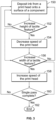
- Figure 3 illustrates a flow chart of a method, according to an example of the present disclosure.
- the control unit 120 operates the printer 108 to deposit the ink 114 from the print head 110 onto the surface 104 of the component 106104.
- the control unit 120 determines, such as via the data 122 in the memory 124, if a height of a tactile feature 102 to be printed on the surface 104 is to be increased. If not, the method returns to 150 (or proceeds to 156).
- the control unit 120 decreases the speed of the print head 110 (via operation of the actuator 118) during the single pass in the direction of arrow A, thereby building up an increased amount of ink at a particular location (defined by the data 122) to form the tactile feature 102.
- Such a feature can have a reduced width.
- the control unit 120 determines, such as via the data 122 in the memory, if a width of a tactile feature 102 to be printed on the surface 104 is to be increased. Step 156 can occur before 152. The method can include step 156 and not step 152, or vice versa.
- the method can return to 150, or optionally proceed to 160. If, however, the width of the tactile feature 102 is to be increased (and the height reduced), the method proceeds from 156 to 158, at which the control unit 120 increases the speed of the print head 110 (via operation of the actuator 118) during the single pass in the direction of arrow A to form the tactile feature 102. Such a feature can have a reduced height.
- control unit 120 determines if the single pass is complete. If not, the method returns to 150. If, however, the control unit 120 determines that the single pass is complete, the method proceeds from 160 to 162, at which the method ends.
- control unit 120 is configured to vary a speed of the print head 110 of the printer 108 during a single pass in the direction of arrow A to form tactile features 102 having different attributes, such as different heights and/or different widths.
- control unit 120 can form such tactile features 102 by varying the speed of the print head 110 using additional passes in the direction of arrow A, the opposite of arrow A, and/or the like.
- control unit 120 is configured to operate the printer to build tactile textured features 102 in a single pass of the print head 110 in the direction of arrow A.
- control unit 120 instead of using an established print clock from an encoder pulse train, the control unit 120 maintains the print clock at a frequency that optimizes head acoustics.
- the control unit 120 can then operate the printer 108 to form the tactile features 102 through the data 122 and varying the speed of the print head 110. Faster print speeds create a shorter texture (that is, a reduced height) while slower print speeds create a taller texture (that is, an increased height).
- the data 122 such as bit map data, accounts for any complex curvature of the surface 104 to achieve a desired printed output.
- the desired output display to be formed on the surface 104 (such as printed text, images, graphics, and/or the like) is stored as the data 122 within the memory 124.
- the output display can be created through one or more steps, which can be conducted by the control unit 120.
- the output display can be created through unit vector mesh unwrapping and image texturing in conjunction with pixel clustering in relation to print speed.
- the control unit 120 sets the print clock set to a specific frequency that optimizes acoustics of the print head 110, such as 30k Hz.
- the control unit 120 constantly sends a 30kHz print clock to the print head 110. Consequently, when printing at different speeds, tactile features 102 having different attributes are formed.
- the tactile features 102 are created in a single pass when jetting at a constant print frequency using an ultraviolet curable translucent ink.
- the speed of the print head 110 dictates the height of the tactile features 102.
- control unit 120 operates the printer 108 to constantly jet the ink 114 from the nozzle(s) 112 during the single pass in the direction of arrow A.
- control unit 120 synchronizes the speed of the print head 110 with the data 122, such as the bit map data, to enable single pass complex curvature textured printing.
- the control unit 120 operates to vary the attributes (for example, heights and/or widths) of the tactile features 102 by controlling the speed of the print head 110 in the direction of arrow A in accordance with the data 122.
- the speed of the print head 110 is varied during the single pass in the direction of arrow A to vary attributes of the tactile features 102.
- the systems and methods described here can be used to print tactile features 102 on complex curved surfaces, such as within an internal cabin of a commercial aircraft.
- the systems and methods described herein can be used in place of traditional embossing processes, which can be inefficient and prone to rework.
- control unit 120 is configured to operate the printer 108 to form the tactile features 102 on a curved surface.
- control unit analyzes the shape of the curved surface, and provides a unit vector map of the curved surface, such as in a two dimensional plane. By unit vector mapping the curved surface, the control unit 120 ensures that the formed tactile features 102 on the curved surface are accurate and undistorted.
- examples of the present disclosure provide a method including controlling, by the control unit 120, the printer 108 to form one or more tactile features 102 on the surface 104 of the component 106.
- Said controlling includes varying a speed of the print head 110 of the printer 108 to vary one or more attributes of the one or more tactile features 102.
- said varying the speed includes varying the speed of the print head 110 of the printer 108 during a single pass of the print head 110 in relation to the surface 104 of the component 106.
- the one or more tactile features 102 include a plurality of tactile features 102. At least two of the plurality of tactile features 102 differ in relation to the one or more attributes. For example, the two different tactile features 102 can have different heights, and/or different widths.
- the attributes include one or both of height or width.
- said varying the speed includes reducing the speed of the print head 110 to form the one or more tactile features 102 having an increased height.
- the one or more tactile features 102 can also have a reduced width.
- said varying the speed includes increasing the speed of the print head 110 to form the one or more tactile features 102 having an increased width.
- the one or more tactile features 102 can also have a reduced height.
- control unit central processing unit
- CPU central processing unit
- computer computer
- RISC reduced instruction set computers
- ASICs application specific integrated circuits
- the control unit 120 may be or include one or more processors that are configured to control operation, as described herein.
- the control unit 120 is configured to execute a set of instructions that are stored in one or more data storage units or elements (such as one or more memories), in order to process data.
- the control unit 120 may include or be coupled to one or more memories.
- the data storage units may also store data or other information as desired or needed.
- the data storage units may be in the form of an information source or a physical memory element within a processing machine.
- the set of instructions may include various commands that instruct the control unit 120 as a processing machine to perform specific operations such as the methods and processes of the various examples of the subject matter described herein.
- the set of instructions may be in the form of a software program.
- the software may be in various forms such as system software or application software. Further, the software may be in the form of a collection of separate programs, a program subset within a larger program, or a portion of a program.
- the software may also include modular programming in the form of object-oriented programming.
- the processing of input data by the processing machine may be in response to user commands, or in response to results of previous processing, or in response to a request made by another processing machine.
- the diagrams of examples herein may illustrate one or more control or processing units, such as the control unit 120.
- the processing or control units may represent circuits, circuitry, or portions thereof that may be implemented as hardware with associated instructions (e.g., software stored on a tangible and non-transitory computer readable storage medium, such as a computer hard drive, ROM, RAM, or the like) that perform the operations described herein.
- the hardware may include state machine circuitry hardwired to perform the functions described herein.
- the hardware may include electronic circuits that include and/or are connected to one or more logic-based devices, such as microprocessors, processors, controllers, or the like.
- control unit 120 may represent processing circuitry such as one or more of a field programmable gate array (FPGA), application specific integrated circuit (ASIC), microprocessor(s), and/or the like.
- FPGA field programmable gate array
- ASIC application specific integrated circuit
- microprocessor(s) and/or the like.
- the circuits in various examples may be configured to execute one or more algorithms to perform functions described herein.
- the one or more algorithms may include aspects of examples disclosed herein, whether or not expressly identified in a flowchart or a method.
- the terms "software” and “firmware” are interchangeable, and include any computer program stored in a data storage unit (for example, one or more memories) for execution by a computer, including RAM memory, ROM memory, EPROM memory, EEPROM memory, and non-volatile RAM (NVRAM) memory.
- a data storage unit for example, one or more memories
- NVRAM non-volatile RAM
- the above data storage unit types are exemplary only, and are thus not limiting as to the types of memory usable for storage of a computer program.
- Figure 4 illustrates a perspective front view of an aircraft 200, according to an example of the present disclosure.
- the aircraft 200 includes a propulsion system 212 that includes engines 214, for example.
- the propulsion system 212 may include more engines 214 than shown.
- the engines 214 are carried by wings 216 of the aircraft 200.
- the engines 214 may be carried by a fuselage 218 and/or an empennage 220.
- the empennage 220 may also support horizontal stabilizers 222 and a vertical stabilizer 224.
- the fuselage 218 of the aircraft 200 defines an internal cabin 230, which includes a flight deck or cockpit, one or more work sections (for example, galleys, personnel carry-on baggage areas, and the like), one or more passenger sections (for example, first class, business class, and coach sections), one or more lavatories, and/or the like.
- the aircraft 200 includes various components having surfaces. Examples of the present disclosure can be used to print tactile surfaces 102 on and/or within the aircraft 200.
- Figure 4 shows an example of an aircraft 200. It is to be understood that the aircraft 200 can be sized, shaped, and configured differently than shown in Figure 4 .
- examples of the present disclosure can be used with various other vehicles.
- the vehicle instead of an aircraft, can be a land-based vehicle, such as an automobile, a bus, a train car, or the like.
- the vehicle can be a watercraft.
- the vehicle can be a spacecraft.
- examples of the present disclosure can be used with fixed structures, such as residential or commercial buildings.
- examples of the present disclosure provide systems and methods for efficiently and effectively printing tactile features on a component. Further, examples of the present disclosure provide methods of printing tactile features that are faster than conventional methods of using multiple passes of a print head.
- a structure, limitation, or element that is "configured to” perform a task or operation is particularly structurally formed, constructed, or adapted in a manner corresponding to the task or operation.
- an object that is merely capable of being modified to perform the task or operation is not “configured to” perform the task or operation as used herein.
Landscapes
- Engineering & Computer Science (AREA)
- Manufacturing & Machinery (AREA)
- Ink Jet (AREA)
Abstract
A method and system include controlling, by a control unit, a printer to form one or more tactile features on a surface of a component. Said controlling includes varying a speed of a print head of the printer to vary one or more attributes of the one or more tactile features. In at least one example, said varying the speed includes varying the speed of the print head of the printer during a single pass of the print head in relation to the surface of the component.
Description
- Examples of the present disclosure generally relate to systems and methods for printing tactile textured surfaces on a surface of a component, such as a portion of a vehicle.
- Printers are used to form features on various substrates. For example, printers can be used to deposit ink onto a surface of a sheet of paper to form text, graphics, and the like. As another example, printers can be used to form decorative surfaces on or within a vehicle, such as within an interior cabin of a commercial aircraft.
- Traditional inkjet printing processes utilize an external encoder pulse generated from a shaft, or virtually, to establish a print clock. The print clock determines when pixels are printed. A print head jetting frequency changes depending on encoder pulses. In order to form raised tactile features on a substrate, numerous printing passes are used to additively form such features at desired heights. Each printing pass occurs over a defined time period, and such process can be time-consuming and inefficient. In general, known inkjet printing methods used to form tactile features typically require the use of numerous print passes to achieve a desired print height.
- G-code is a computer numerical control programming language that can be used with respect to printing. G-code is typically used in computer-assisted manufacturing processes to control tools, machines, and the like. In known printing processes, G-code defines how to operate a servo motor of a printer. A G-code printing process is typically read left to right, then top to bottom. For example, N is a block of code, G dictates the type of command, F specifies a feed rate, and X is a position. A servo motor generates an encoder signal as the servo motor rotates. The signal can be simulated or obtained from the shaft rotation. Print head drive electronics generate a print clock based on the received encoder signal. Generally, encoder signal frequency is significantly higher than print clock frequency to ensure accurate printing. Encoder pulses generated are directly related to print speed. The faster the servo spins, the more encounter pulses are generated. The drive electronics send data to the print head in the form of a bit map. Pixels are sequentially printed as print clock pulses are received. In such an example, a traditional printing process can be used to form tactile features by printing an ultraviolet (UV) curable ink with many passes. and curing the ink in between passes. Again, such a process is time consuming and inefficient.
- A need exists for a method of efficiently and effectively printing tactile features on a component. A need exists for a method of printing tactile features that is faster than known methods of using multiple passes of a print head.
- With those needs in mind, certain examples of the present disclosure provide a method including controlling, by a control unit, a printer to form one or more tactile features on a surface of a component. Said controlling includes varying a speed of a print head of the printer to vary one or more attributes of the one or more tactile features.
- In at least one example, the one or more tactile features include a plurality of tactile features. At least two of the plurality of tactile features differ in relation to the one or more attributes.
- In at least one example, said varying the speed includes varying the speed of the print head of the printer during a single pass of the print head in relation to the surface of the component.
- The attributes can include one or both of height or width. In at least one example, said varying the speed includes reducing the speed of the print head to form the one or more tactile features having an increased height. Such one or more tactile features can have a reduced width. In at least one example, said varying the speed includes increasing the speed of the print head to form the one or more tactile features having an increased width. Such one or more tactile features can have a reduced height.
- The method can also include creating, by the control unit, a desired output display that includes the one or more tactile features through unit vector mapping.
- In at least one example, said controlling further includes jetting ink from one or more nozzles of the print head at a constant print frequency.
- The component can be on or within a vehicle. The surface can be curved.
- Certain examples of the present disclosure provide a system including a printer having a print head. A control unit is configured to control the printer to form one or more tactile features on a surface of a component. The control unit is configured to vary a speed of the print head of the printer to vary one or more attributes of the one or more tactile features.
-
-
Figure 1 illustrates a simplified block diagram of a system, according to an example of the present disclosure. -
Figure 2 illustrates a simplified lateral view of a component, according to an example of the present disclosure. -
Figure 3 illustrates a flow chart of a method, according to an example of the present disclosure. -
Figure 4 illustrates a perspective front view of an aircraft, according to an example of the present disclosure. - The foregoing summary, as well as the following detailed description of certain examples will be better understood when read in conjunction with the appended drawings. As used herein, an element or step recited in the singular and preceded by the word "a" or "an" should be understood as not necessarily excluding the plural of the elements or steps. Further, references to "one example" are not intended to be interpreted as excluding the existence of additional examples that also incorporate the recited features. Moreover, unless explicitly stated to the contrary, examples "comprising" or "having" an element or a plurality of elements having a particular condition can include additional elements not having that condition.
- As described herein, examples of the present disclosure provide systems and methods for printing tactile textured features on a component, such as may have a complex curvature, in a single pass of a print head.
-
Figure 1 illustrates a simplified block diagram of asystem 100, according to an example of the present disclosure. Thesystem 100 is configured to print one or moretactile features 102 on asurface 104 of acomponent 106. In at least one example, thecomponent 106 is a portion of a vehicle, such as an outer surface of a fuselage, a wing, or the like. As another example, thecomponent 106 is within an internal cabin of the vehicle, such as a wall, ceiling, floor, or the like within the vehicle. As another example, thecomponent 106 can be a structure on or within a fixed structure. As another example, thecomponent 106 can be a substrate, such as paper, a panel, or the like. Thesurface 104 of thecomponent 106 can be flat and planar. As another example, thesurface 104 can include one more curves, such can have a regular or irregular curvature. - The
system 100 includes aprinter 108 having aprint head 110, which includes one ormore nozzles 112 configured to depositink 114 onto thesurface 104. In at least one example, theprint head 110 includes asingle nozzle 112. As another example, theprint head 110 includes two, three, four, five, ormore nozzles 112. Aswath 116 of theprint head 110 is a width across the one ormore nozzles 112. - The
printer 108 is coupled to anactuator 118, which is configured to move theprint head 110. In at least one example, theprint head 110 includes a single axis servo motor having a linear actuator. Theactuator 118 is configured to move theprint head 110 over a pass in relation to thesurface 104 of thecomponent 106. Theactuator 118 can be separate and distinct from theprinter 108. As another example, theprinter 108 includes theactuator 118. - A
control unit 120 is in communication with theprinter 108 and theactuator 118, such as through one or more wired or wireless connections. Thecontrol unit 120 is configured to operate theactuator 118 and theprinter 108 to form thetactile features 102 on thesurface 104 of thecomponent 106 based ondata 122 stored within amemory 124 that is communication with thecontrol unit 120, such as through one or more wired or wireless connections. For example, thedata 122 can be a bit map of thetactile features 102 to be formed on thesurface 104 of thecomponent 106. Thememory 124 can be separate and distinct from thecontrol unit 120. As another example, thecontrol unit 120 includes thememory 124. - In operation, in order to form the
tactile features 102, theprinter 108 is moved in a single pass in the direction of arrow A (such as from left to right, right to left, top to bottom, or bottom to top) in relation to thesurface 104. Thecontrol unit 120 operates theprinter 108 to deposit theink 114 onto thesurface 104 to form thetactile features 102 during the single pass of theprinter 108. In order to form thetactile features 102 having different attributes (such a heights and widths), the control unit varies the speed of theprinter 108 in the direction of arrow A during the single pass, instead of operating the printer over multiple passes. -
Figure 2 illustrates a simplified lateral view of thecomponent 106, according to an example of the present disclosure. Referring toFigures 1 and 2 , thecontrol unit 120 operates theprinter 108 to form thetactile features print head 110 in the direction of arrow A. As shown, thetactile feature 102a has a first width W1 along a portion of thesurface 104, and a first height H1 above thesurface 104. Thetactile feature 102a has a second width W2 along a portion of thesurface 104, and a second height H2 above thesurface 104. The first width W1 differs from the second width W2. As shown, the first width W1 is greater than the second width W2. The first height H1 differs from the second height H2. As shown, the first height H1 is less than the second height H2. - In order to form a taller tactile feature having a thinner width, such as the
tactile feature 102b, thecontrol unit 120 decreases the speed of theprint head 110 during the single pass in the direction of arrow A, thereby concentrating more ink droplets at a tighter location. Consequently, the ink droplets form the higher, thinnertactile feature 102b. In contrast, in order to form a shorter tactile feature having a greater width, the control unit increases the speed of theprint head 110 during the single pass in the direction of arrow A, thereby spreading the ink droplets over a wider area, and which reduces the build-up in height. In this manner, thecontrol unit 120 operates theprinter 108 to formtactile features 102 having different attributes (such as different heights and/or widths) on thesurface 104 of thecomponent 106 by varying the speed of theprint head 110, as controlled by theactuator 118, during the single pass in the direction of arrow A. -
Figure 3 illustrates a flow chart of a method, according to an example of the present disclosure. Referring toFigures 1-3 , at 150, thecontrol unit 120 operates theprinter 108 to deposit theink 114 from theprint head 110 onto thesurface 104 of the component 106104. At 152, thecontrol unit 120 determines, such as via thedata 122 in thememory 124, if a height of atactile feature 102 to be printed on thesurface 104 is to be increased. If not, the method returns to 150 (or proceeds to 156). - If, however, the height of the
tactile feature 102 is to be increased, thecontrol unit 120 decreases the speed of the print head 110 (via operation of the actuator 118) during the single pass in the direction of arrow A, thereby building up an increased amount of ink at a particular location (defined by the data 122) to form thetactile feature 102. Such a feature can have a reduced width. - At 156, the
control unit 120 determines, such as via thedata 122 in the memory, if a width of atactile feature 102 to be printed on thesurface 104 is to be increased. Step 156 can occur before 152. The method can include step 156 and not step 152, or vice versa. - If the width of a
tactile feature 102 is to be increased, the method can return to 150, or optionally proceed to 160. If, however, the width of thetactile feature 102 is to be increased (and the height reduced), the method proceeds from 156 to 158, at which thecontrol unit 120 increases the speed of the print head 110 (via operation of the actuator 118) during the single pass in the direction of arrow A to form thetactile feature 102. Such a feature can have a reduced height. - At 160, the
control unit 120 determines if the single pass is complete. If not, the method returns to 150. If, however, thecontrol unit 120 determines that the single pass is complete, the method proceeds from 160 to 162, at which the method ends. - As described herein, the
control unit 120 is configured to vary a speed of theprint head 110 of theprinter 108 during a single pass in the direction of arrow A to formtactile features 102 having different attributes, such as different heights and/or different widths. Optionally, thecontrol unit 120 can form suchtactile features 102 by varying the speed of theprint head 110 using additional passes in the direction of arrow A, the opposite of arrow A, and/or the like. - In at least one example, the
control unit 120 is configured to operate the printer to build tactiletextured features 102 in a single pass of theprint head 110 in the direction of arrow A. In at least one example, instead of using an established print clock from an encoder pulse train, thecontrol unit 120 maintains the print clock at a frequency that optimizes head acoustics. Thecontrol unit 120 can then operate theprinter 108 to form thetactile features 102 through thedata 122 and varying the speed of theprint head 110. Faster print speeds create a shorter texture (that is, a reduced height) while slower print speeds create a taller texture (that is, an increased height). Thedata 122, such as bit map data, accounts for any complex curvature of thesurface 104 to achieve a desired printed output. - In at least one example, the desired output display to be formed on the surface 104 (such as printed text, images, graphics, and/or the like) is stored as the
data 122 within thememory 124. The output display can be created through one or more steps, which can be conducted by thecontrol unit 120. For example, the output display can be created through unit vector mesh unwrapping and image texturing in conjunction with pixel clustering in relation to print speed. - In at least one example, rather than defining the print clock with encoder pulses received from a servo motor, the
control unit 120 sets the print clock set to a specific frequency that optimizes acoustics of theprint head 110, such as 30k Hz. Thecontrol unit 120 constantly sends a 30kHz print clock to theprint head 110. Consequently, when printing at different speeds,tactile features 102 having different attributes are formed. - In at least one example, the
tactile features 102 are created in a single pass when jetting at a constant print frequency using an ultraviolet curable translucent ink. The speed of theprint head 110 dictates the height of the tactile features 102. - In at least one example, the
control unit 120 operates theprinter 108 to constantly jet theink 114 from the nozzle(s) 112 during the single pass in the direction of arrow A. In order to form thetextured features 102 having different attributes, thecontrol unit 120 synchronizes the speed of theprint head 110 with thedata 122, such as the bit map data, to enable single pass complex curvature textured printing. Thecontrol unit 120 operates to vary the attributes (for example, heights and/or widths) of thetactile features 102 by controlling the speed of theprint head 110 in the direction of arrow A in accordance with thedata 122. The speed of theprint head 110 is varied during the single pass in the direction of arrow A to vary attributes of the tactile features 102. - The systems and methods described here can be used to print
tactile features 102 on complex curved surfaces, such as within an internal cabin of a commercial aircraft. The systems and methods described herein can be used in place of traditional embossing processes, which can be inefficient and prone to rework. - In at least one example, the
control unit 120 is configured to operate theprinter 108 to form thetactile features 102 on a curved surface. For example, the control unit analyzes the shape of the curved surface, and provides a unit vector map of the curved surface, such as in a two dimensional plane. By unit vector mapping the curved surface, thecontrol unit 120 ensures that the formedtactile features 102 on the curved surface are accurate and undistorted. - As described herein, examples of the present disclosure provide a method including controlling, by the
control unit 120, theprinter 108 to form one or moretactile features 102 on thesurface 104 of thecomponent 106. Said controlling includes varying a speed of theprint head 110 of theprinter 108 to vary one or more attributes of the one or moretactile features 102. In at least one example, said varying the speed includes varying the speed of theprint head 110 of theprinter 108 during a single pass of theprint head 110 in relation to thesurface 104 of thecomponent 106. - In at least one example, the one or more
tactile features 102 include a plurality oftactile features 102. At least two of the plurality oftactile features 102 differ in relation to the one or more attributes. For example, the two differenttactile features 102 can have different heights, and/or different widths. - In at least one example, the attributes include one or both of height or width. For example, said varying the speed includes reducing the speed of the
print head 110 to form the one or moretactile features 102 having an increased height. In this example, the one or moretactile features 102 can also have a reduced width. In at least one example, said varying the speed includes increasing the speed of theprint head 110 to form the one or moretactile features 102 having an increased width. In this example, the one or moretactile features 102 can also have a reduced height. - As used herein, the term "control unit," "central processing unit," "CPU," "computer," or the like may include any processor-based or microprocessor-based system including systems using microcontrollers, reduced instruction set computers (RISC), application specific integrated circuits (ASICs), logic circuits, and any other circuit or processor including hardware, software, or a combination thereof capable of executing the functions described herein. Such are exemplary only, and are thus not intended to limit in any way the definition and/or meaning of such terms. For example, the
control unit 120 may be or include one or more processors that are configured to control operation, as described herein. - The
control unit 120 is configured to execute a set of instructions that are stored in one or more data storage units or elements (such as one or more memories), in order to process data. For example, thecontrol unit 120 may include or be coupled to one or more memories. The data storage units may also store data or other information as desired or needed. The data storage units may be in the form of an information source or a physical memory element within a processing machine. - The set of instructions may include various commands that instruct the
control unit 120 as a processing machine to perform specific operations such as the methods and processes of the various examples of the subject matter described herein. The set of instructions may be in the form of a software program. The software may be in various forms such as system software or application software. Further, the software may be in the form of a collection of separate programs, a program subset within a larger program, or a portion of a program. The software may also include modular programming in the form of object-oriented programming. The processing of input data by the processing machine may be in response to user commands, or in response to results of previous processing, or in response to a request made by another processing machine. - The diagrams of examples herein may illustrate one or more control or processing units, such as the
control unit 120. It is to be understood that the processing or control units may represent circuits, circuitry, or portions thereof that may be implemented as hardware with associated instructions (e.g., software stored on a tangible and non-transitory computer readable storage medium, such as a computer hard drive, ROM, RAM, or the like) that perform the operations described herein. The hardware may include state machine circuitry hardwired to perform the functions described herein. Optionally, the hardware may include electronic circuits that include and/or are connected to one or more logic-based devices, such as microprocessors, processors, controllers, or the like. Optionally, thecontrol unit 120 may represent processing circuitry such as one or more of a field programmable gate array (FPGA), application specific integrated circuit (ASIC), microprocessor(s), and/or the like. The circuits in various examples may be configured to execute one or more algorithms to perform functions described herein. The one or more algorithms may include aspects of examples disclosed herein, whether or not expressly identified in a flowchart or a method. - As used herein, the terms "software" and "firmware" are interchangeable, and include any computer program stored in a data storage unit (for example, one or more memories) for execution by a computer, including RAM memory, ROM memory, EPROM memory, EEPROM memory, and non-volatile RAM (NVRAM) memory. The above data storage unit types are exemplary only, and are thus not limiting as to the types of memory usable for storage of a computer program.
-
Figure 4 illustrates a perspective front view of anaircraft 200, according to an example of the present disclosure. Theaircraft 200 includes apropulsion system 212 that includesengines 214, for example. Optionally, thepropulsion system 212 may includemore engines 214 than shown. Theengines 214 are carried bywings 216 of theaircraft 200. In other examples, theengines 214 may be carried by afuselage 218 and/or anempennage 220. Theempennage 220 may also supporthorizontal stabilizers 222 and avertical stabilizer 224. Thefuselage 218 of theaircraft 200 defines aninternal cabin 230, which includes a flight deck or cockpit, one or more work sections (for example, galleys, personnel carry-on baggage areas, and the like), one or more passenger sections (for example, first class, business class, and coach sections), one or more lavatories, and/or the like. Referring toFigures 1-4 , theaircraft 200 includes various components having surfaces. Examples of the present disclosure can be used to printtactile surfaces 102 on and/or within theaircraft 200. -
Figure 4 shows an example of anaircraft 200. It is to be understood that theaircraft 200 can be sized, shaped, and configured differently than shown inFigure 4 . Optionally, examples of the present disclosure can be used with various other vehicles. For example, instead of an aircraft, the vehicle can be a land-based vehicle, such as an automobile, a bus, a train car, or the like. As another example, the vehicle can be a watercraft. As another example, the vehicle can be a spacecraft. Optionally, examples of the present disclosure can be used with fixed structures, such as residential or commercial buildings. - Further, the disclosure comprises examples according to the following clauses:
- Clause 1. A method comprising: controlling, by a control unit, a printer to form one or more tactile features on a surface of a component, wherein said controlling comprises varying a speed of a print head of the printer to vary one or more attributes of the one or more tactile features.
- Clause 2. The method of Clause 1, wherein the one or more tactile features comprise a plurality of tactile features, and wherein at least two of the plurality of tactile features differ in relation to the one or more attributes.
- Clause 3. The method of Clauses 1 or 2, wherein said varying the speed comprises varying the speed of the print head of the printer during a single pass of the print head in relation to the surface of the component.
- Clause 4. The method of any of Clauses 1-3, wherein the attributes comprise one or both of height or width.
- Clause 5. The method of Clause 4, wherein said varying the speed comprises reducing the speed of the print head to form the one or more tactile features having an increased height.
- Clause 6. The method of Clause 5, wherein the one or more tactile features have a reduced width.
- Clause 7. The method of any of Clauses 4-6, wherein said varying the speed comprises increasing the speed of the print head to form the one or more tactile features having an increased width.
- Clause 8. The method of Clause 7, wherein the one or more tactile features having a reduced height.
- Clause 9. The method of any of Clauses 1-8, further comprising creating, by the control unit, a desired output display that includes the one or more tactile features through unit vector mapping.
- Clause 10. The method of any of Clauses 1-9, wherein said controlling further comprises jetting ink from one or more nozzles of the print head at a constant print frequency.
- Clause 11. The method of any of Clauses 1-10, wherein the component is on or within a vehicle, and wherein the surface is curved.
- Clause 12. A system comprising: a printer including a print head; and a control unit configured to control the printer to form one or more tactile features on a surface of a component, wherein the control unit is configured to vary a speed of the print head of the printer to vary one or more attributes of the one or more tactile features.
- Clause 13. The system of Clause 12, wherein the one or more tactile features comprise a plurality of tactile features, and wherein at least two of the plurality of tactile features differ in relation to the one or more attributes.
- Clause 14. The system of Clauses 12 or 13, wherein the control unit is configured to vary the speed of the print head of the printer during a single pass of the print head in relation to the surface of the component.
- Clause 15. The system of any of Clauses 12-14, wherein the attributes comprise one or both of height or width, wherein the control unit is configured to vary the speed by (a) reducing the speed of the print head to form the one or more tactile features having an increased height, and (b) increasing the speed of the print head to form the one or more tactile features having an increased width.
- Clause 16. The system of any of Clauses 12-15, wherein the control unit is further configured to create a desired output display that includes the one or more tactile features through unit vector mapping.
- Clause 17. The system of any of Clauses 12-16, wherein the control unit is configured to control the printer by jetting ink from one or more nozzles of the print head at a constant print frequency.
- Clause 18. The system of any of Clauses 12-17, wherein the component is on or within a vehicle, and wherein the surface is curved.
- Clause 19. A method comprising: controlling, by a control unit, a printer to form a plurality of tactile features on a surface of a component, wherein said controlling comprises varying a speed of a print head of the printer during a single pass to vary one on or both of height or width of the plurality of tactile features, wherein at least two of the plurality of tactile features differ in relation to one or both of the height or the width, said varying the speed comprises: reducing the speed of the print head to form at least one of the plurality of tactile features having an increased height, and increasing the speed of the print head to form at least one of the plurality of tactile features having an increased width.
- Clause 20. The method of Clause 19, further comprising: creating, by the control unit, a desired output display that includes the one or more tactile features through unit vector mapping; and jetting ink from one or more nozzles of the print head at a constant print frequency.
- As described herein, examples of the present disclosure provide systems and methods for efficiently and effectively printing tactile features on a component. Further, examples of the present disclosure provide methods of printing tactile features that are faster than conventional methods of using multiple passes of a print head.
- While various spatial and directional terms, such as top, bottom, lower, mid, lateral, horizontal, vertical, front and the like can be used to describe examples of the present disclosure, it is understood that such terms are merely used with respect to the orientations shown in the drawings. The orientations can be inverted, rotated, or otherwise changed, such that an upper portion is a lower portion, and vice versa, horizontal becomes vertical, and the like.
- As used herein, a structure, limitation, or element that is "configured to" perform a task or operation is particularly structurally formed, constructed, or adapted in a manner corresponding to the task or operation. For purposes of clarity and the avoidance of doubt, an object that is merely capable of being modified to perform the task or operation is not "configured to" perform the task or operation as used herein.
- It is to be understood that the above description is intended to be illustrative, and not restrictive. For example, the above-described examples (and/or aspects thereof) can be used in combination with each other. In addition, many modifications can be made to adapt a particular situation or material to the teachings of the various examples of the disclosure without departing from their scope. While the dimensions and types of materials described herein are intended to define the aspects of the various examples of the disclosure, the examples are by no means limiting and are exemplary examples. Many other examples will be apparent to those of skill in the art upon reviewing the above description. The scope of the various examples of the disclosure should, therefore, be determined with reference to the appended claims, along with the full scope of equivalents to which such claims are entitled. In the appended claims and the detailed description herein, the terms "including" and "in which" are used as the plain-English equivalents of the respective terms "comprising" and "wherein." Moreover, the terms "first," "second," and "third," etc. are used merely as labels, and are not intended to impose numerical requirements on their objects. Further, the limitations of the following claims are not written in means-plus-function format and are not intended to be interpreted based on 35 U.S.C. § 112(f), unless and until such claim limitations expressly use the phrase "means for" followed by a statement of function void of further structure.
- This written description uses examples to disclose the various examples of the disclosure, including the best mode, and also to enable any person skilled in the art to practice the various examples of the disclosure, including making and using any devices or systems and performing any incorporated methods. The patentable scope of the various examples of the disclosure is defined by the claims, and can include other examples that occur to those skilled in the art. Such other examples are intended to be within the scope of the claims if the examples have structural elements that do not differ from the literal language of the claims, or if the examples include equivalent structural elements with insubstantial differences from the literal language of the claims.
Claims (15)
- A method comprising:controlling, by a control unit (120), a printer (108) to form one or more tactile features (102) on a surface (104) of a component (106),wherein said controlling comprises varying a speed of a print head (110) of the printer (108) to vary one or more attributes of the one or more tactile features (102).
- The method of claim 1, wherein the one or more tactile features (102) comprise a plurality of tactile features (102), and wherein at least two of the plurality of tactile features (102) differ in relation to the one or more attributes.
- The method of claim 1 or 2, wherein said varying the speed comprises varying the speed of the print head (110) of the printer (108) during a single pass of the print head (110) in relation to the surface (104) of the component (106).
- The method of any one of claims 1-4, wherein the attributes comprise one or both of height or width.
- The method of claim 4, wherein said varying the speed comprises reducing the speed of the print head (110) to form the one or more tactile features (102) having an increased height; and optionally
wherein the one or more tactile features (102) have a reduced width. - The method of any one of claims 4-5, wherein said varying the speed comprises increasing the speed of the print head (110) to form the one or more tactile features (102) having an increased width; and optionally
wherein the one or more tactile features (102) having a reduced height. - The method of any one of claims 1-6, further comprising creating, by the control unit (120), a desired output display that includes the one or more tactile features (102) through unit vector mapping; and/or optionallywherein said controlling further comprises jetting ink (114) from one or more nozzles (112) of the print head (110) at a constant print frequency; and/or optionallywherein the component (106) is on or within a vehicle, and wherein the surface (104) is curved.
- A system (100) comprising:a printer (108) including a print head (110); anda control unit (120) configured to control the printer (108) to form one or more tactile features (102) on a surface (104) of a component (106),wherein the control unit (120) is configured to vary a speed of the print head (110) of the printer (108) to vary one or more attributes of the one or more tactile features (102).
- The system (100) of claim 8, wherein the one or more tactile features (102) comprise a plurality of tactile features (102), and wherein at least two of the plurality of tactile features (102) differ in relation to the one or more attributes; and/or optionally
wherein the control unit (120) is configured to vary the speed of the print head (110) of the printer (108) during a single pass of the print head (110) in relation to the surface (104) of the component (106). - The system (100) of any one of claims 8-9, wherein the attributes comprise one or both of height or width, wherein the control unit (120) is configured to vary the speed by (a) reducing the speed of the print head (110) to form the one or more tactile features (102) having an increased height, and (b) increasing the speed of the print head (110) to form the one or more tactile features (102) having an increased width.
- The system (100) of any one of claims 8-10, wherein the control unit (120) is further configured to create a desired output display that includes the one or more tactile features (102) through unit vector mapping.
- The system (100) of any one of claims 8-11, wherein the control unit (120) is configured to control the printer (108) by jetting ink (114) from one or more nozzles (112) of the print head (110) at a constant print frequency.
- The system (100) of any one of claims 8-12, wherein the component (106) is on or within a vehicle, and wherein the surface (104) is curved.
- The method as claimed in claim 1, wherein at least two of the plurality of tactile features (102) differ in relation to one or both of the height or the width,
said varying the speed comprises:reducing the speed of the print head (110) to form at least one of the plurality of tactile features (102) having an increased height, andincreasing the speed of the print head (110) to form at least one of the plurality of tactile features (102) having an increased width. - The method of claim 14, further comprising:creating, by the control unit (120), a desired output display that includes the one or more tactile features (102) through unit vector mapping; andjetting ink (114) from one or more nozzles (112) of the print head (110) at a constant print frequency.
Applications Claiming Priority (1)
| Application Number | Priority Date | Filing Date | Title |
|---|---|---|---|
| US18/183,604 US12570086B2 (en) | 2023-03-14 | 2023-03-14 | Systems and methods for printing a tactile textured surface on a surface of a component |
Publications (1)
| Publication Number | Publication Date |
|---|---|
| EP4431298A1 true EP4431298A1 (en) | 2024-09-18 |
Family
ID=89619675
Family Applications (1)
| Application Number | Title | Priority Date | Filing Date |
|---|---|---|---|
| EP24151980.0A Pending EP4431298A1 (en) | 2023-03-14 | 2024-01-15 | Systems and methods for printiing a tactile textured surface on a surface of a component |
Country Status (2)
| Country | Link |
|---|---|
| US (1) | US12570086B2 (en) |
| EP (1) | EP4431298A1 (en) |
Citations (7)
| Publication number | Priority date | Publication date | Assignee | Title |
|---|---|---|---|---|
| JP2010162801A (en) * | 2009-01-16 | 2010-07-29 | Seiko Epson Corp | Fluid jetting apparatus and fluid jetting method |
| US20110177303A1 (en) * | 2008-07-31 | 2011-07-21 | Takuya Suehiro | Decorative surface structure of synthetic resin molded article, method for producing the same and automobile interior part |
| CN103521410A (en) * | 2013-10-14 | 2014-01-22 | 大连理工大学 | Automatic printing method of three-dimensional pattern on vehicle body surface |
| JP2017124777A (en) * | 2016-01-15 | 2017-07-20 | 株式会社レイズエンジニアリング | Vehicle wheel and method for decorating vehicle wheel |
| JP2017193113A (en) * | 2016-04-21 | 2017-10-26 | コニカミノルタ株式会社 | Inkjet recording device and image forming method of inkjet recording device |
| US20170341305A1 (en) * | 2016-05-31 | 2017-11-30 | Nike, Inc. | Method of printing a contoured object using color and structural layers |
| US20220274398A1 (en) * | 2020-04-07 | 2022-09-01 | Abb Schweiz Ag | Ink-jet type vehicle coating machine and vehicle coating method |
Family Cites Families (16)
| Publication number | Priority date | Publication date | Assignee | Title |
|---|---|---|---|---|
| GB9611582D0 (en) * | 1996-06-04 | 1996-08-07 | Thin Film Technology Consultan | 3D printing and forming of structures |
| US6945063B2 (en) | 2002-06-28 | 2005-09-20 | Marine Desalination Systems, L.L.C. | Apparatus and method for harvesting atmospheric moisture |
| US8828226B2 (en) | 2003-03-01 | 2014-09-09 | The Trustees Of Boston University | System for assessing the efficacy of stored red blood cells using microvascular networks |
| US20050052516A1 (en) | 2003-09-05 | 2005-03-10 | Wilde John C. | Laminate panel for use in structrual components |
| JP2006035184A (en) * | 2004-07-30 | 2006-02-09 | Seiko Epson Corp | Droplet coating method, droplet coating apparatus, electro-optical device, and electronic apparatus |
| US20060068109A1 (en) * | 2004-09-15 | 2006-03-30 | Airbus Deutschland Gmbh | Painting device, painting arrangement, method for painting a curved surface of an object, and use of an inkjet device for painting an aircraft |
| EP2799150B1 (en) | 2013-05-02 | 2016-04-27 | Hexagon Technology Center GmbH | Graphical application system |
| US8317166B2 (en) | 2010-11-10 | 2012-11-27 | Koch-Glitsch, Lp | Liquid collection and distribution device for mass transfer column and process involving same |
| JP5642125B2 (en) | 2012-08-24 | 2014-12-17 | 富士フイルム株式会社 | Inkjet recording method |
| US9272465B2 (en) | 2012-10-28 | 2016-03-01 | The Boeing Company | High-quality flame-retardant decorative finish for interior panels |
| EP2894136B1 (en) | 2014-01-08 | 2019-12-04 | The Boeing Company | Improved method of making fire resistant sustainable aircraft interior panels |
| CN106232696B (en) | 2014-04-24 | 2020-06-05 | 3M创新有限公司 | Fluid control films having hydrophilic surfaces, methods of making the same, and methods for cleaning structured surfaces |
| US9718302B2 (en) | 2015-09-22 | 2017-08-01 | The Boeing Company | Decorative laminate with non-visible light activated material and system and method for using the same |
| KR102129517B1 (en) | 2015-12-23 | 2020-07-06 | 사빅 글로벌 테크놀러지스 비.브이. | Reinforced foam structure, manufacturing method thereof, and product |
| US11034428B2 (en) | 2018-08-10 | 2021-06-15 | The Boeing Compny | Anti-microbial decorative laminate |
| US12275520B2 (en) | 2020-02-11 | 2025-04-15 | The Boeing Company | Liquid-diverting panel assemblies |
-
2023
- 2023-03-14 US US18/183,604 patent/US12570086B2/en active Active
-
2024
- 2024-01-15 EP EP24151980.0A patent/EP4431298A1/en active Pending
Patent Citations (7)
| Publication number | Priority date | Publication date | Assignee | Title |
|---|---|---|---|---|
| US20110177303A1 (en) * | 2008-07-31 | 2011-07-21 | Takuya Suehiro | Decorative surface structure of synthetic resin molded article, method for producing the same and automobile interior part |
| JP2010162801A (en) * | 2009-01-16 | 2010-07-29 | Seiko Epson Corp | Fluid jetting apparatus and fluid jetting method |
| CN103521410A (en) * | 2013-10-14 | 2014-01-22 | 大连理工大学 | Automatic printing method of three-dimensional pattern on vehicle body surface |
| JP2017124777A (en) * | 2016-01-15 | 2017-07-20 | 株式会社レイズエンジニアリング | Vehicle wheel and method for decorating vehicle wheel |
| JP2017193113A (en) * | 2016-04-21 | 2017-10-26 | コニカミノルタ株式会社 | Inkjet recording device and image forming method of inkjet recording device |
| US20170341305A1 (en) * | 2016-05-31 | 2017-11-30 | Nike, Inc. | Method of printing a contoured object using color and structural layers |
| US20220274398A1 (en) * | 2020-04-07 | 2022-09-01 | Abb Schweiz Ag | Ink-jet type vehicle coating machine and vehicle coating method |
Also Published As
| Publication number | Publication date |
|---|---|
| US12570086B2 (en) | 2026-03-10 |
| US20240308203A1 (en) | 2024-09-19 |
Similar Documents
| Publication | Publication Date | Title |
|---|---|---|
| EP2687438B1 (en) | Control system of aircraft, aircraft, control program for aircraft, and control method for aircraft | |
| CN109484621B (en) | Active wing-torsion mechanism and control system | |
| EP3395539B1 (en) | Color three-dimensional printing method and three-dimensional printing equipment | |
| US10293601B2 (en) | Automated controls for contoured surface inkjet printing | |
| US10479481B2 (en) | Process and machine for reducing a drag component of a horizontal stabilizer on an aircraft | |
| CN105083536A (en) | System and method for optimizing horizontal tail loads | |
| EP3456625B1 (en) | Airplane takeoff trims utilizing stabilizers and elevators | |
| US20230117551A1 (en) | Process and machine for load alleviation | |
| US20130020432A1 (en) | System and method for an air vehicle | |
| CN105759613A (en) | Control method and device for tilt rotorcraft | |
| US12570086B2 (en) | Systems and methods for printing a tactile textured surface on a surface of a component | |
| EP4201685B1 (en) | Liquid discharge apparatus, liquid discharge method, and carrier medium | |
| CN110316353A (en) | System and method for improving the operation of aircraft | |
| WO2023164682A3 (en) | Process for controlling extrusion speed in 3d printing systems | |
| CN114357629A (en) | Geometric shape curved surface deformation method and system based on nested FFD control body | |
| US20250303632A1 (en) | Systems and methods for applying a tactile textured substrate to a surface of a structure | |
| EP4541599A1 (en) | Systems and methods for printing on a substrate | |
| CN112026364B (en) | Code spraying system, code spraying control method, device, equipment and storage medium | |
| US20240082865A1 (en) | Mask forming system for protecting a structure and a method of forming a mask for the same | |
| CN121100063A (en) | Coating device, coating method, and program | |
| EP4516518A1 (en) | Methods for forming liquid management patterns on a surface of a structure of a vehicle | |
| US20230398568A1 (en) | Methods for forming liquid management patterns on a surface of a structure of a vehicle | |
| US11053016B1 (en) | Aircraft movement control system | |
| JP2004123010A (en) | Control surface control method and device, and aircraft | |
| Meckstroth et al. | Control focused multidisciplinary design optimization of tailless fighter aircraft |
Legal Events
| Date | Code | Title | Description |
|---|---|---|---|
| PUAI | Public reference made under article 153(3) epc to a published international application that has entered the european phase |
Free format text: ORIGINAL CODE: 0009012 |
|
| STAA | Information on the status of an ep patent application or granted ep patent |
Free format text: STATUS: THE APPLICATION HAS BEEN PUBLISHED |
|
| AK | Designated contracting states |
Kind code of ref document: A1 Designated state(s): AL AT BE BG CH CY CZ DE DK EE ES FI FR GB GR HR HU IE IS IT LI LT LU LV MC ME MK MT NL NO PL PT RO RS SE SI SK SM TR |
|
| STAA | Information on the status of an ep patent application or granted ep patent |
Free format text: STATUS: REQUEST FOR EXAMINATION WAS MADE |
|
| 17P | Request for examination filed |
Effective date: 20250124 |