EP4431273A1 - Glass panel assembly and roof assembly of a vehicle provided therewith - Google Patents
Glass panel assembly and roof assembly of a vehicle provided therewith Download PDFInfo
- Publication number
- EP4431273A1 EP4431273A1 EP24159597.4A EP24159597A EP4431273A1 EP 4431273 A1 EP4431273 A1 EP 4431273A1 EP 24159597 A EP24159597 A EP 24159597A EP 4431273 A1 EP4431273 A1 EP 4431273A1
- Authority
- EP
- European Patent Office
- Prior art keywords
- glass panel
- assembly according
- vehicle
- lower face
- assembly
- Prior art date
- Legal status (The legal status is an assumption and is not a legal conclusion. Google has not performed a legal analysis and makes no representation as to the accuracy of the status listed.)
- Pending
Links
- 239000011521 glass Substances 0.000 title claims abstract description 134
- 238000010030 laminating Methods 0.000 claims abstract description 9
- 239000000853 adhesive Substances 0.000 claims description 7
- 230000001070 adhesive effect Effects 0.000 claims description 7
- 239000011324 bead Substances 0.000 claims description 3
- 239000003292 glue Substances 0.000 claims description 3
- 230000000712 assembly Effects 0.000 description 12
- 238000000429 assembly Methods 0.000 description 12
- 238000005538 encapsulation Methods 0.000 description 3
- 230000007246 mechanism Effects 0.000 description 2
- 230000005540 biological transmission Effects 0.000 description 1
- 230000002349 favourable effect Effects 0.000 description 1
- 238000005286 illumination Methods 0.000 description 1
- 239000000463 material Substances 0.000 description 1
Images



Classifications
-
- B—PERFORMING OPERATIONS; TRANSPORTING
- B60—VEHICLES IN GENERAL
- B60J—WINDOWS, WINDSCREENS, NON-FIXED ROOFS, DOORS, OR SIMILAR DEVICES FOR VEHICLES; REMOVABLE EXTERNAL PROTECTIVE COVERINGS SPECIALLY ADAPTED FOR VEHICLES
- B60J7/00—Non-fixed roofs; Roofs with movable panels, e.g. rotary sunroofs
- B60J7/02—Non-fixed roofs; Roofs with movable panels, e.g. rotary sunroofs of sliding type, e.g. comprising guide shoes
- B60J7/04—Non-fixed roofs; Roofs with movable panels, e.g. rotary sunroofs of sliding type, e.g. comprising guide shoes with rigid plate-like element or elements, e.g. open roofs with harmonica-type folding rigid panels
- B60J7/043—Sunroofs e.g. sliding above the roof
-
- B—PERFORMING OPERATIONS; TRANSPORTING
- B32—LAYERED PRODUCTS
- B32B—LAYERED PRODUCTS, i.e. PRODUCTS BUILT-UP OF STRATA OF FLAT OR NON-FLAT, e.g. CELLULAR OR HONEYCOMB, FORM
- B32B17/00—Layered products essentially comprising sheet glass, or glass, slag, or like fibres
-
- B—PERFORMING OPERATIONS; TRANSPORTING
- B32—LAYERED PRODUCTS
- B32B—LAYERED PRODUCTS, i.e. PRODUCTS BUILT-UP OF STRATA OF FLAT OR NON-FLAT, e.g. CELLULAR OR HONEYCOMB, FORM
- B32B17/00—Layered products essentially comprising sheet glass, or glass, slag, or like fibres
- B32B17/06—Layered products essentially comprising sheet glass, or glass, slag, or like fibres comprising glass as the main or only constituent of a layer, next to another layer of a specific material
-
- B—PERFORMING OPERATIONS; TRANSPORTING
- B32—LAYERED PRODUCTS
- B32B—LAYERED PRODUCTS, i.e. PRODUCTS BUILT-UP OF STRATA OF FLAT OR NON-FLAT, e.g. CELLULAR OR HONEYCOMB, FORM
- B32B17/00—Layered products essentially comprising sheet glass, or glass, slag, or like fibres
- B32B17/06—Layered products essentially comprising sheet glass, or glass, slag, or like fibres comprising glass as the main or only constituent of a layer, next to another layer of a specific material
- B32B17/10—Layered products essentially comprising sheet glass, or glass, slag, or like fibres comprising glass as the main or only constituent of a layer, next to another layer of a specific material of synthetic resin
-
- B—PERFORMING OPERATIONS; TRANSPORTING
- B32—LAYERED PRODUCTS
- B32B—LAYERED PRODUCTS, i.e. PRODUCTS BUILT-UP OF STRATA OF FLAT OR NON-FLAT, e.g. CELLULAR OR HONEYCOMB, FORM
- B32B17/00—Layered products essentially comprising sheet glass, or glass, slag, or like fibres
- B32B17/06—Layered products essentially comprising sheet glass, or glass, slag, or like fibres comprising glass as the main or only constituent of a layer, next to another layer of a specific material
- B32B17/10—Layered products essentially comprising sheet glass, or glass, slag, or like fibres comprising glass as the main or only constituent of a layer, next to another layer of a specific material of synthetic resin
- B32B17/10005—Layered products essentially comprising sheet glass, or glass, slag, or like fibres comprising glass as the main or only constituent of a layer, next to another layer of a specific material of synthetic resin laminated safety glass or glazing
- B32B17/10009—Layered products essentially comprising sheet glass, or glass, slag, or like fibres comprising glass as the main or only constituent of a layer, next to another layer of a specific material of synthetic resin laminated safety glass or glazing characterized by the number, the constitution or treatment of glass sheets
- B32B17/10036—Layered products essentially comprising sheet glass, or glass, slag, or like fibres comprising glass as the main or only constituent of a layer, next to another layer of a specific material of synthetic resin laminated safety glass or glazing characterized by the number, the constitution or treatment of glass sheets comprising two outer glass sheets
-
- B—PERFORMING OPERATIONS; TRANSPORTING
- B32—LAYERED PRODUCTS
- B32B—LAYERED PRODUCTS, i.e. PRODUCTS BUILT-UP OF STRATA OF FLAT OR NON-FLAT, e.g. CELLULAR OR HONEYCOMB, FORM
- B32B17/00—Layered products essentially comprising sheet glass, or glass, slag, or like fibres
- B32B17/06—Layered products essentially comprising sheet glass, or glass, slag, or like fibres comprising glass as the main or only constituent of a layer, next to another layer of a specific material
- B32B17/10—Layered products essentially comprising sheet glass, or glass, slag, or like fibres comprising glass as the main or only constituent of a layer, next to another layer of a specific material of synthetic resin
- B32B17/10005—Layered products essentially comprising sheet glass, or glass, slag, or like fibres comprising glass as the main or only constituent of a layer, next to another layer of a specific material of synthetic resin laminated safety glass or glazing
- B32B17/10165—Functional features of the laminated safety glass or glazing
- B32B17/10541—Functional features of the laminated safety glass or glazing comprising a light source or a light guide
-
- B—PERFORMING OPERATIONS; TRANSPORTING
- B32—LAYERED PRODUCTS
- B32B—LAYERED PRODUCTS, i.e. PRODUCTS BUILT-UP OF STRATA OF FLAT OR NON-FLAT, e.g. CELLULAR OR HONEYCOMB, FORM
- B32B3/00—Layered products comprising a layer with external or internal discontinuities or unevennesses, or a layer of non-planar shape; Layered products comprising a layer having particular features of form
- B32B3/02—Layered products comprising a layer with external or internal discontinuities or unevennesses, or a layer of non-planar shape; Layered products comprising a layer having particular features of form characterised by features of form at particular places, e.g. in edge regions
- B32B3/08—Layered products comprising a layer with external or internal discontinuities or unevennesses, or a layer of non-planar shape; Layered products comprising a layer having particular features of form characterised by features of form at particular places, e.g. in edge regions characterised by added members at particular parts
-
- B—PERFORMING OPERATIONS; TRANSPORTING
- B60—VEHICLES IN GENERAL
- B60J—WINDOWS, WINDSCREENS, NON-FIXED ROOFS, DOORS, OR SIMILAR DEVICES FOR VEHICLES; REMOVABLE EXTERNAL PROTECTIVE COVERINGS SPECIALLY ADAPTED FOR VEHICLES
- B60J1/00—Windows; Windscreens; Accessories therefor
- B60J1/001—Double glazing for vehicles
-
- B—PERFORMING OPERATIONS; TRANSPORTING
- B60—VEHICLES IN GENERAL
- B60J—WINDOWS, WINDSCREENS, NON-FIXED ROOFS, DOORS, OR SIMILAR DEVICES FOR VEHICLES; REMOVABLE EXTERNAL PROTECTIVE COVERINGS SPECIALLY ADAPTED FOR VEHICLES
- B60J10/00—Sealing arrangements
- B60J10/80—Sealing arrangements specially adapted for opening panels, e.g. doors
- B60J10/84—Sealing arrangements specially adapted for opening panels, e.g. doors arranged on the vehicle body
-
- B—PERFORMING OPERATIONS; TRANSPORTING
- B60—VEHICLES IN GENERAL
- B60J—WINDOWS, WINDSCREENS, NON-FIXED ROOFS, DOORS, OR SIMILAR DEVICES FOR VEHICLES; REMOVABLE EXTERNAL PROTECTIVE COVERINGS SPECIALLY ADAPTED FOR VEHICLES
- B60J7/00—Non-fixed roofs; Roofs with movable panels, e.g. rotary sunroofs
-
- B—PERFORMING OPERATIONS; TRANSPORTING
- B60—VEHICLES IN GENERAL
- B60Q—ARRANGEMENT OF SIGNALLING OR LIGHTING DEVICES, THE MOUNTING OR SUPPORTING THEREOF OR CIRCUITS THEREFOR, FOR VEHICLES IN GENERAL
- B60Q3/00—Arrangement of lighting devices for vehicle interiors; Lighting devices specially adapted for vehicle interiors
- B60Q3/20—Arrangement of lighting devices for vehicle interiors; Lighting devices specially adapted for vehicle interiors for lighting specific fittings of passenger or driving compartments; mounted on specific fittings of passenger or driving compartments
- B60Q3/208—Sun roofs; Windows
-
- B—PERFORMING OPERATIONS; TRANSPORTING
- B60—VEHICLES IN GENERAL
- B60Q—ARRANGEMENT OF SIGNALLING OR LIGHTING DEVICES, THE MOUNTING OR SUPPORTING THEREOF OR CIRCUITS THEREFOR, FOR VEHICLES IN GENERAL
- B60Q3/00—Arrangement of lighting devices for vehicle interiors; Lighting devices specially adapted for vehicle interiors
- B60Q3/60—Arrangement of lighting devices for vehicle interiors; Lighting devices specially adapted for vehicle interiors characterised by optical aspects
- B60Q3/62—Arrangement of lighting devices for vehicle interiors; Lighting devices specially adapted for vehicle interiors characterised by optical aspects using light guides
-
- C—CHEMISTRY; METALLURGY
- C03—GLASS; MINERAL OR SLAG WOOL
- C03C—CHEMICAL COMPOSITION OF GLASSES, GLAZES OR VITREOUS ENAMELS; SURFACE TREATMENT OF GLASS; SURFACE TREATMENT OF FIBRES OR FILAMENTS MADE FROM GLASS, MINERALS OR SLAGS; JOINING GLASS TO GLASS OR OTHER MATERIALS
- C03C27/00—Joining pieces of glass to pieces of other inorganic material; Joining glass to glass other than by fusing
- C03C27/06—Joining glass to glass by processes other than fusing
- C03C27/10—Joining glass to glass by processes other than fusing with the aid of adhesive specially adapted for that purpose
-
- F—MECHANICAL ENGINEERING; LIGHTING; HEATING; WEAPONS; BLASTING
- F21—LIGHTING
- F21V—FUNCTIONAL FEATURES OR DETAILS OF LIGHTING DEVICES OR SYSTEMS THEREOF; STRUCTURAL COMBINATIONS OF LIGHTING DEVICES WITH OTHER ARTICLES, NOT OTHERWISE PROVIDED FOR
- F21V7/00—Reflectors for light sources
- F21V7/0008—Reflectors for light sources providing for indirect lighting
-
- B—PERFORMING OPERATIONS; TRANSPORTING
- B32—LAYERED PRODUCTS
- B32B—LAYERED PRODUCTS, i.e. PRODUCTS BUILT-UP OF STRATA OF FLAT OR NON-FLAT, e.g. CELLULAR OR HONEYCOMB, FORM
- B32B2307/00—Properties of the layers or laminate
- B32B2307/70—Other properties
- B32B2307/732—Dimensional properties
- B32B2307/737—Dimensions, e.g. volume or area
- B32B2307/7375—Linear, e.g. length, distance or width
- B32B2307/7376—Thickness
-
- B—PERFORMING OPERATIONS; TRANSPORTING
- B32—LAYERED PRODUCTS
- B32B—LAYERED PRODUCTS, i.e. PRODUCTS BUILT-UP OF STRATA OF FLAT OR NON-FLAT, e.g. CELLULAR OR HONEYCOMB, FORM
- B32B2605/00—Vehicles
-
- B—PERFORMING OPERATIONS; TRANSPORTING
- B32—LAYERED PRODUCTS
- B32B—LAYERED PRODUCTS, i.e. PRODUCTS BUILT-UP OF STRATA OF FLAT OR NON-FLAT, e.g. CELLULAR OR HONEYCOMB, FORM
- B32B2605/00—Vehicles
- B32B2605/08—Cars
-
- F—MECHANICAL ENGINEERING; LIGHTING; HEATING; WEAPONS; BLASTING
- F21—LIGHTING
- F21W—INDEXING SCHEME ASSOCIATED WITH SUBCLASSES F21K, F21L, F21S and F21V, RELATING TO USES OR APPLICATIONS OF LIGHTING DEVICES OR SYSTEMS
- F21W2106/00—Interior vehicle lighting devices
-
- F—MECHANICAL ENGINEERING; LIGHTING; HEATING; WEAPONS; BLASTING
- F21—LIGHTING
- F21W—INDEXING SCHEME ASSOCIATED WITH SUBCLASSES F21K, F21L, F21S and F21V, RELATING TO USES OR APPLICATIONS OF LIGHTING DEVICES OR SYSTEMS
- F21W2107/00—Use or application of lighting devices on or in particular types of vehicles
- F21W2107/10—Use or application of lighting devices on or in particular types of vehicles for land vehicles
Definitions
- the invention generally relates to glass panel assemblies intended for use in roof assemblies of vehicles.
- the invention relates to such glass panel assemblies which are provided with at least one light incoupling assembly.
- Such glass panel assemblies may be used for providing a patterned illumination of the passenger compartment of a vehicle.
- the glass panel assembly in accordance with the present invention combines a number of advantageous features, such as for example a low weight, high strength and very effective light incoupling into the glass panel.
- the rectangular prism mainly is made of ultra clear glass. This optimizes the light incoupling into the glass panel (resulting, among others, in a reduction of loss of light).
- the rectangular prism preferably is connected to the second glass panel lower face by means of a layer of an optic adhesive.
- an optic adhesive combines the advantageous features of achieving an effective bond between the prism and the second glass panel lower face as well as assuring an effective transmission (incoupling) of light into the second glass panel.
- the layer of the optic adhesive may extend over the entire respective face of the prism which faces the second glass panel lower face (and in such a case said respective face of the prism preferably will be flat or substantially flat).
- the layer of an optic adhesive may be an ultra-thin layer.
- the layered glass panel may be of two different types.
- the layered glass panel may be a fixed panel, wherein near to the circumference of the second glass panel lower face a glue bead is provided intended for connecting the layered glass panel with, and for defining a watertight seal relative to, a part of the vehicle (for example a frame part of the roof assembly or the so-called body-in-white of the vehicle).
- a glue bead is provided intended for connecting the layered glass panel with, and for defining a watertight seal relative to, a part of the vehicle (for example a frame part of the roof assembly or the so-called body-in-white of the vehicle).
- the glass panel has a fixed position relative to the vehicle.
- the layered glass panel may be a movable panel, wherein the circumference of the second glass panel lower face is intended to directly or indirectly (for example via an encapsulation surrounding at least part of the second glass panel outer edge) cooperate with a seal provided on a part of the vehicle (for example a frame part of the roof assembly or the so-called body-in-white of the vehicle).
- a movable panel for example may be used for closing and opening a roof opening provided in a fixed roof part of the vehicle.
- the first glass panel and second glass panel are provided with identical or substantially identical outlines. This, among others, has a favorable effect on the overall strength of the layered glass panel.
- first glass panel and the second glass panel have identical or substantially identical thicknesses, for example a thickness of substantially 2.1 mm.
- light outcoupling provisions are provided in a desired pattern at the interface between the second glass panel upper face and laminating layer.
- Such light outcoupling provisions may assure that the light is visible (for example from inside a passenger compartment of the vehicle) in a desired magnitude and at desired locations (for example for creating a desired light pattern).
- the light outcoupling provisions may be part of or may be integrated into (or be positioned on top of) the laminating layer and/or of the second glass panel, but also may be separate provisions positioned therebetween.
- the desired pattern may be such that the provisions are provided according to a local pattern only, but it also is conceivable that such provisions are provided continuously over at least part of the interface.
- the present invention relates to a roof assembly of a vehicle, comprising a frame part surrounding a roof opening in a roof part of the vehicle and a glass panel assembly according to the previous mounted fixedly or movably in said frame part.
- a top part of a vehicle 1 is represented which has a fixed roof part 2 to which a frame part 3 (only represented in figure 3 ) is mounted of which inner sides surround (or define) a roof opening 4.
- a frame part 3 (only represented in figure 3 ) is mounted of which inner sides surround (or define) a roof opening 4.
- One part (for example forward part) of the roof opening 4 is covered by a movable panel 5, whereas the remaining part (for example rear part) of the roof opening is covered by a fixed panel 6.
- the movable panel 5 and fixed panel 6 are schematically represented in their respective positions relative to the fixed roof part 2.
- the movable panel 5 may move to another position (for example partly backwards over the fixed panel 6) for at least partly freeing the respective part of the roof opening 4.
- Mechanisms for achieving such a movement of the movable panel 5 are well-known in the art and thus not further described here.
- both the movable panel 5 and the fixed panel 6 define layered glass panels which are part of glass panel assemblies in accordance with the present invention and which will be described in detail while referring to figures 3 and 4 . It should be noted, however, that in other embodiments also only one of the movable and fixed panels could define such a layered glass panel.
- light incoupling assemblies 7a-d and 8a-d are indicated schematically in dotted lines.
- Such light incoupling assemblies may be provided in any desired pattern (for example at all edges of the panels 5,6 as represented, or for example only at some of the edges, for example only at the lateral edges of the panels, thus only 7a,b and 8a,b, and in a similar manner for both panels or differently forboth panels).
- a location of the light incoupling assemblies in the vicinity of the edges of the panels 5,6 is preferable, also other locations may be conceived.
- the layered glass panel comprises a first (here upper) glass panel 9 with a first glass panel upper face 10 and an opposite first glass panel lower face 11, as well as a second (here lower) glass panel 12 with a second glass panel upper face 13 and an opposite second glass panel lower face 14.
- the first glass panel 9 and second glass panel 12 by means of a laminating layer 15 are laminated to each other at the first glass panel lower face 11 and the second glass panel upper face 13.
- a laminating layer 15 may be of any known type and may have properties chosen in accordance with the specific application.
- FIG 3 also shows the light incoupling assembly 8a which is provided on the second glass panel lower face 14.
- Said light incoupling assembly 8a (as well as any of the other light incoupling assemblies) comprises at least one light source 16 with light incoupling element 17.
- the light incoupling element 17 specifically comprises a rectangular prism which mainly may be made of ultra clear glass.
- the rectangular prism 17 is connected to the second glass panel lower face 14 by means of a (preferably ultra-thin) layer of an optic adhesive 18.
- the light source 16 may be attached to the second glass panel 12 in any appropriate manner.
- a glue bead 19 or alike is provided intended for connecting the layered glass panel 6 with, and for defining a watertight seal relative to, a part of the vehicle, such as, in the illustrated embodiment, a frame part 3 which, as stated before, may surround the roof opening 4 (or, as an alternative, the so-called body-in-white).
- the first glass panel 9 and second glass panel 12, as viewed in a top plan view, are provided with identical or substantially identical outlines, as partly represented in figure 3 by the fact that the right-handed outer edges of the first and second glass panels 9,12 substantially coincide.
- light outcoupling provisions which may be provided in a desired pattern at the interface between the second glass panel upper face 13 and laminating layer 15, which may assure that light is emitted from the second glass panel 12 at desired locations (as illustrated schematically by arrow 20).
- Figure 4 basically only differs from figure 3 in that the layered glass panel now defines part of a movable panel 5.
- Components similar to components of the fixed panel 6 according to figure 3 have identical reference numbers.
- the main difference is the provision of an encapsulation 21 at an edge of the movable panel 5 to which a cover element 22 (for hiding the light incoupling assembly 7a from sight) and part of a driving mechanism 23 for the movable panel 5 are attached.
- a seal 24 (only visible in figure 2 ) may be provided on a part of the vehicle for cooperating with, for example, the encapsulation 21 (or another part of the movable panel 5).
- the first glass panel 9 and the second glass panel 12 have identical or substantially identical thicknesses, for example a thickness of substantially 2.1 mm. Both panels may be manufactured from identical or different glass materials.
Landscapes
- Engineering & Computer Science (AREA)
- Mechanical Engineering (AREA)
- Chemical & Material Sciences (AREA)
- Ceramic Engineering (AREA)
- Life Sciences & Earth Sciences (AREA)
- Chemical Kinetics & Catalysis (AREA)
- General Chemical & Material Sciences (AREA)
- Geochemistry & Mineralogy (AREA)
- Materials Engineering (AREA)
- Organic Chemistry (AREA)
- General Engineering & Computer Science (AREA)
- Joining Of Glass To Other Materials (AREA)
Abstract
A glass panel assembly is provided intended for use in a roof assembly of a vehicle. It has a layered glass panel comprising a first glass panel (9) with a first glass panel upper face (10) and an opposite first glass panel lower face (11) and a second glass panel (12) with a second glass panel upper face (13) and an opposite second glass panel lower face (14). The first glass panel (9) and second glass panel (12) by means of a laminating layer (15) are laminated to each other at the first glass panel lower face (11) and the second glass panel upper face (13). At least one light incoupling assembly (8a) is provided on the second glass panel lower face (14), which light incoupling assembly (8a) comprises at least one light source (16) with light incoupling element (17). The light incoupling element (17) comprises a rectangular prism.
Description
- The invention generally relates to glass panel assemblies intended for use in roof assemblies of vehicles. In particular the invention relates to such glass panel assemblies which are provided with at least one light incoupling assembly. Such glass panel assemblies, among others, may be used for providing a patterned illumination of the passenger compartment of a vehicle.
- In existing glass panel assemblies on top of a basic layer of glass an additional layer of glass is needed which, considered in a top plan view, is smaller than the basic layer of glass because a light incoupling is achieved from the sides of the glass and sufficient room should be provided for the positioning of light incoupling assemblies. Such existing glass panel assemblies may comprise layered glass panels with two, or even three separate glass panels positioned on top of each other.
- It is an object of the present invention to provide an improved glass panel assembly of such a type.
- Thus, in accordance with a first aspect of the present invention, a glass panel assembly is provided which is intended for use in a roof assembly of a vehicle and which has a layered glass panel comprising a first glass panel with a first glass panel upper face and an opposite first glass panel lower face and a second glass panel with a second glass panel upper face and an opposite second glass panel lower face, wherein the first glass panel and second glass panel by means of a laminating layer are laminated to each other at the first glass panel lower face and the second glass panel upper face, and wherein at least one light incoupling assembly is provided on the second glass panel lower face, which light incoupling assembly comprises at least one light source with light incoupling element and wherein the light incoupling element comprises a rectangular prism.
- The glass panel assembly in accordance with the present invention combines a number of advantageous features, such as for example a low weight, high strength and very effective light incoupling into the glass panel.
- In one embodiment of the glass panel assembly, the rectangular prism mainly is made of ultra clear glass. This optimizes the light incoupling into the glass panel (resulting, among others, in a reduction of loss of light).
- In such an embodiment the rectangular prism preferably is connected to the second glass panel lower face by means of a layer of an optic adhesive. Such an optic adhesive combines the advantageous features of achieving an effective bond between the prism and the second glass panel lower face as well as assuring an effective transmission (incoupling) of light into the second glass panel. The layer of the optic adhesive may extend over the entire respective face of the prism which faces the second glass panel lower face (and in such a case said respective face of the prism preferably will be flat or substantially flat).
- For further improving the light incoupling, the layer of an optic adhesive may be an ultra-thin layer.
- Basically, the layered glass panel may be of two different types. As a first type, the layered glass panel may be a fixed panel, wherein near to the circumference of the second glass panel lower face a glue bead is provided intended for connecting the layered glass panel with, and for defining a watertight seal relative to, a part of the vehicle (for example a frame part of the roof assembly or the so-called body-in-white of the vehicle). Thus, in such an embodiment the glass panel has a fixed position relative to the vehicle.
- Alternatively, as a second type, the layered glass panel may be a movable panel, wherein the circumference of the second glass panel lower face is intended to directly or indirectly (for example via an encapsulation surrounding at least part of the second glass panel outer edge) cooperate with a seal provided on a part of the vehicle (for example a frame part of the roof assembly or the so-called body-in-white of the vehicle). Such a movable panel for example may be used for closing and opening a roof opening provided in a fixed roof part of the vehicle.
- Preferably, the first glass panel and second glass panel, as viewed in a top plan view, are provided with identical or substantially identical outlines. This, among others, has a favorable effect on the overall strength of the layered glass panel.
- Further it is conceivable that the first glass panel and the second glass panel have identical or substantially identical thicknesses, for example a thickness of substantially 2.1 mm.
- In yet another embodiment of the glass panel assembly according to the present invention, light outcoupling provisions are provided in a desired pattern at the interface between the second glass panel upper face and laminating layer. Such light outcoupling provisions may assure that the light is visible (for example from inside a passenger compartment of the vehicle) in a desired magnitude and at desired locations (for example for creating a desired light pattern). The light outcoupling provisions may be part of or may be integrated into (or be positioned on top of) the laminating layer and/or of the second glass panel, but also may be separate provisions positioned therebetween. The desired pattern may be such that the provisions are provided according to a local pattern only, but it also is conceivable that such provisions are provided continuously over at least part of the interface.
- In a second aspect, the present invention relates to a roof assembly of a vehicle, comprising a frame part surrounding a roof opening in a roof part of the vehicle and a glass panel assembly according to the previous mounted fixedly or movably in said frame part.
- Hereinafter the invention will be elucidated while referring to the drawings, in which:
-
Figure 1 schematically shows part of a vehicle in which a glass panel assembly in accordance with the invention may be incorporated; -
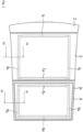
Figure 2 schematically shows a top plan view of part of the vehicle; -
Figure 3 schematically shows a partial cross section according to III-III infigure 2 , and -
Figure 4 schematically shows a partial cross section according to IV-IV infigure 2 . - In
figure 1 a top part of avehicle 1 is represented which has afixed roof part 2 to which a frame part 3 (only represented infigure 3 ) is mounted of which inner sides surround (or define) aroof opening 4. One part (for example forward part) of theroof opening 4 is covered by amovable panel 5, whereas the remaining part (for example rear part) of the roof opening is covered by afixed panel 6. - In
figure 2 themovable panel 5 andfixed panel 6 are schematically represented in their respective positions relative to thefixed roof part 2. Of course, themovable panel 5 may move to another position (for example partly backwards over the fixed panel 6) for at least partly freeing the respective part of theroof opening 4. Mechanisms for achieving such a movement of themovable panel 5 are well-known in the art and thus not further described here. - As an exemplary embodiment, both the
movable panel 5 and thefixed panel 6 define layered glass panels which are part of glass panel assemblies in accordance with the present invention and which will be described in detail while referring tofigures 3 and4 . It should be noted, however, that in other embodiments also only one of the movable and fixed panels could define such a layered glass panel. - In
figure 2 light incoupling assemblies 7a-d and 8a-d are indicated schematically in dotted lines. Such light incoupling assemblies may be provided in any desired pattern (for example at all edges of thepanels fig- , a location of the light incoupling assemblies in the vicinity of the edges of theure 2panels - For a detailed description of the layered glass panel defining part of the
fixed panel 6, reference is made tofigure 3 . The layered glass panel comprises a first (here upper)glass panel 9 with a first glass panelupper face 10 and an opposite first glass panellower face 11, as well as a second (here lower)glass panel 12 with a second glass panelupper face 13 and an opposite second glass panellower face 14. - The
first glass panel 9 andsecond glass panel 12 by means of a laminatinglayer 15 are laminated to each other at the first glass panellower face 11 and the second glass panelupper face 13. Such a laminatinglayer 15 may be of any known type and may have properties chosen in accordance with the specific application. -
Figure 3 also shows thelight incoupling assembly 8a which is provided on the second glass panellower face 14. Saidlight incoupling assembly 8a (as well as any of the other light incoupling assemblies) comprises at least onelight source 16 withlight incoupling element 17. Thelight incoupling element 17 specifically comprises a rectangular prism which mainly may be made of ultra clear glass. - In the illustrated embodiment the
rectangular prism 17 is connected to the second glass panellower face 14 by means of a (preferably ultra-thin) layer of anoptic adhesive 18. Thelight source 16 may be attached to thesecond glass panel 12 in any appropriate manner. - Near to the circumference of the second glass panel lower face 14 a
glue bead 19 or alike is provided intended for connecting thelayered glass panel 6 with, and for defining a watertight seal relative to, a part of the vehicle, such as, in the illustrated embodiment, aframe part 3 which, as stated before, may surround the roof opening 4 (or, as an alternative, the so-called body-in-white). - The
first glass panel 9 andsecond glass panel 12, as viewed in a top plan view, are provided with identical or substantially identical outlines, as partly represented infigure 3 by the fact that the right-handed outer edges of the first andsecond glass panels - Not illustrated in detail are light outcoupling provisions which may be provided in a desired pattern at the interface between the second glass panel
upper face 13 and laminatinglayer 15, which may assure that light is emitted from thesecond glass panel 12 at desired locations (as illustrated schematically by arrow 20). -
Figure 4 basically only differs fromfigure 3 in that the layered glass panel now defines part of amovable panel 5. Components similar to components of thefixed panel 6 according tofigure 3 have identical reference numbers. The main difference is the provision of anencapsulation 21 at an edge of themovable panel 5 to which a cover element 22 (for hiding thelight incoupling assembly 7a from sight) and part of adriving mechanism 23 for themovable panel 5 are attached. A seal 24 (only visible infigure 2 ) may be provided on a part of the vehicle for cooperating with, for example, the encapsulation 21 (or another part of the movable panel 5). - In the embodiments according to
figures 3 and4 , thefirst glass panel 9 and thesecond glass panel 12 have identical or substantially identical thicknesses, for example a thickness of substantially 2.1 mm. Both panels may be manufactured from identical or different glass materials. - The invention is not limited to the embodiments described which may be varied widely within the scope of the invention as defined by the appending claims.
Claims (12)
- Glass panel assembly intended for use in a roof assembly of a vehicle, with a layered glass panel comprising a first glass panel with a first glass panel upper face and an opposite first glass panel lower face and a second glass panel with a second glass panel upper face and an opposite second glass panel lower face, wherein the first glass panel and second glass panel by means of a laminating layer are laminated to each other at the first glass panel lower face and the second glass panel upper face, and wherein at least one light incoupling assembly is provided on the second glass panel lower face, which light incoupling assembly comprises at least one light source with light incoupling element and wherein the light incoupling element comprises a rectangular prism.
- Glass panel assembly according to claim 1,
wherein the rectangular prism mainly is made of ultra clear glass. - Glass panel assembly according to claim 2,
wherein the rectangular prism is connected to the second glass panel lower face by means of a layer of an optic adhesive. - Glass panel assembly according to claim 3,
wherein the layer of an optic adhesive is an ultra-thin layer. - Glass panel assembly according to claim 1,
wherein the layered glass panel is a fixed panel and wherein near to the circumference of the second glass panel lower face a glue bead is provided intended for connecting the layered glass panel with, and for defining a watertight seal relative to, a part of the vehicle. - Glass panel assembly according to claim 1,
wherein the layered glass panel is a movable panel and wherein the circumference of the second glass panel lower face is intended to directly or indirectly cooperate with a seal provided on a part of the vehicle. - Glass panel assembly according to claim 5 or 6, wherein the said part of the vehicle is a frame part of the roof assembly or is the so-called body-in-white of the vehicle.
- Glass panel assembly according to claim 1,
wherein the first glass panel and second glass panel, as viewed in a top plan view, are provided with identical or substantially identical outlines. - Glass panel assembly according to claim 1,
wherein the first glass panel and the second glass panel have identical or substantially identical thicknesses. - Glass panel assembly according to claim 9,
wherein the first glass panel and the second glass panel have a thickness of substantially 2.1 mm. - Glass panel assembly according to claim 1,
wherein light outcoupling provisions are provided in a desired pattern at the interface between the second glass panel upper face and laminating layer. - Roof assembly of a vehicle, comprising a frame part surrounding a roof opening in a roof part of the vehicle and a glass panel assembly according to any of the previous claims mounted fixedly or movably in said frame part.
Applications Claiming Priority (1)
| Application Number | Priority Date | Filing Date | Title |
|---|---|---|---|
| CN202310259724.7A CN118664978A (en) | 2023-03-17 | 2023-03-17 | Glass panel assembly and vehicle roof assembly provided with the same |
Publications (1)
| Publication Number | Publication Date |
|---|---|
| EP4431273A1 true EP4431273A1 (en) | 2024-09-18 |
Family
ID=90059272
Family Applications (1)
| Application Number | Title | Priority Date | Filing Date |
|---|---|---|---|
| EP24159597.4A Pending EP4431273A1 (en) | 2023-03-17 | 2024-02-26 | Glass panel assembly and roof assembly of a vehicle provided therewith |
Country Status (4)
| Country | Link |
|---|---|
| US (1) | US20240308309A1 (en) |
| EP (1) | EP4431273A1 (en) |
| KR (1) | KR20240140817A (en) |
| CN (1) | CN118664978A (en) |
Families Citing this family (2)
| Publication number | Priority date | Publication date | Assignee | Title |
|---|---|---|---|---|
| DE112023000846T5 (en) * | 2022-02-09 | 2024-11-21 | AGC Inc. | VEHICLE LAMINATED GLASS |
| DE102023116605A1 (en) * | 2023-06-23 | 2024-12-24 | Webasto SE | vehicle window with lighting device |
Citations (3)
| Publication number | Priority date | Publication date | Assignee | Title |
|---|---|---|---|---|
| EP2240345B1 (en) * | 2007-12-12 | 2013-09-18 | Innotec, Corp. | Light for vehicles |
| WO2013167832A1 (en) * | 2012-05-10 | 2013-11-14 | Saint-Gobain Glass France | Illuminating glazing with incorporated deflector |
| CN112810415A (en) * | 2021-02-05 | 2021-05-18 | 江苏集萃智能液晶科技有限公司 | Transparent distributed skylight of can adjusting luminance |
-
2023
- 2023-03-17 CN CN202310259724.7A patent/CN118664978A/en active Pending
-
2024
- 2024-02-26 EP EP24159597.4A patent/EP4431273A1/en active Pending
- 2024-03-04 KR KR1020240030527A patent/KR20240140817A/en active Pending
- 2024-03-14 US US18/605,168 patent/US20240308309A1/en active Pending
Patent Citations (3)
| Publication number | Priority date | Publication date | Assignee | Title |
|---|---|---|---|---|
| EP2240345B1 (en) * | 2007-12-12 | 2013-09-18 | Innotec, Corp. | Light for vehicles |
| WO2013167832A1 (en) * | 2012-05-10 | 2013-11-14 | Saint-Gobain Glass France | Illuminating glazing with incorporated deflector |
| CN112810415A (en) * | 2021-02-05 | 2021-05-18 | 江苏集萃智能液晶科技有限公司 | Transparent distributed skylight of can adjusting luminance |
Also Published As
| Publication number | Publication date |
|---|---|
| KR20240140817A (en) | 2024-09-24 |
| CN118664978A (en) | 2024-09-20 |
| US20240308309A1 (en) | 2024-09-19 |
Similar Documents
| Publication | Publication Date | Title |
|---|---|---|
| US20240308309A1 (en) | Glass panel assembly and roof assembly of a vehicle provided therewith | |
| US8500192B2 (en) | Whole glass roof for a motor vehicle | |
| US11642873B2 (en) | Interlayer film for laminated glass, laminated glass, and image display system | |
| JP5617488B2 (en) | Sunshade for vehicle | |
| US20110033667A1 (en) | Complex partition glass consisting of at least two adjacent glass elements, and method for producing said complex partition glass | |
| US7086693B1 (en) | Glass roof assembly and method of retrofitting a vehicle | |
| US20220355580A1 (en) | Intermediate film for laminated glass, laminated glass, and image display system | |
| US10745057B2 (en) | Vehicle pillar structure | |
| US20070182217A1 (en) | Transparent vehicle roof | |
| US11660837B2 (en) | Composite glass pane | |
| CN219405679U (en) | Glass panel assembly and roof assembly of vehicle provided with same | |
| US20180126832A1 (en) | Vehicle with moonroof and panoramic glass | |
| US10696330B2 (en) | Upper part structure of vehicle body | |
| CN101138949B (en) | Canopy for convertible cars | |
| CN218316180U (en) | Triangular window assembly for vehicle and vehicle having same | |
| GB2168742A (en) | Automobile window structures | |
| WO2015060153A1 (en) | Panel assembly and support structure of laminated panel in vehicle body | |
| US5609387A (en) | Lining panel for a sliding roof for a vehicle | |
| US9676259B2 (en) | Cover for a motor vehicle roof | |
| MXPA06002045A (en) | Multi-piece roof with reinforcement. | |
| US20240424984A1 (en) | Vehicle window with lighting unit | |
| CN215321913U (en) | A two-in-one functional glass for the front cover of a dimmable sunroof | |
| CN220576772U (en) | Glass panel assembly | |
| EP4509308A1 (en) | Composite glazing provided with segments of flat glass strips | |
| US20250214321A1 (en) | Vehicle window and vehicle comprising such a vehicle window |
Legal Events
| Date | Code | Title | Description |
|---|---|---|---|
| PUAI | Public reference made under article 153(3) epc to a published international application that has entered the european phase |
Free format text: ORIGINAL CODE: 0009012 |
|
| STAA | Information on the status of an ep patent application or granted ep patent |
Free format text: STATUS: THE APPLICATION HAS BEEN PUBLISHED |
|
| AK | Designated contracting states |
Kind code of ref document: A1 Designated state(s): AL AT BE BG CH CY CZ DE DK EE ES FI FR GB GR HR HU IE IS IT LI LT LU LV MC ME MK MT NL NO PL PT RO RS SE SI SK SM TR |
|
| STAA | Information on the status of an ep patent application or granted ep patent |
Free format text: STATUS: REQUEST FOR EXAMINATION WAS MADE |
|
| 17P | Request for examination filed |
Effective date: 20250314 |